

Page 1

White Paper
June 1999
ECG02030699A
Prepared by ECG Technology
Communications Group
Compaq Computer Corporation
Contents
Understanding Fibre
Channel Transmission .............. 3
Understanding Fiber Types....... 4
Connection Components .......... 5
Hubs........................................ 6
Gigabit Interface Converters..... 6
Fibre Channel Cables and
Connectors.............................. 7
Interconnecting System
Components.............................. 8
Overview of System
Components............................ 8
RAID Array 4000
Configurations.......................... 9
Using Infrastructure Cabling....11
Compaq StorageWorks
RAID Array 4000 Using
Infrastructure Cabling..............13
Testing......................................14
Test Specifications..................14
Handling Fiber and Fiber
Connectors...............................15
Acknowledgments and
References................................15
Understanding Compaq
StorageWorks RAID Array 4000
and Infrastructure Cabling
Abstract: Compaq StorageWorks RAID Array 40001 (RA4000)
storage solutions shatter distance, connectivity, capacity, and
bandwidth limitations of small computer systems interface (SCSI)
technology. RA4000 allows highly scalable, high-performance
storage solutions for the most demanding applications. While SCSI
technology continues to satisfy the needs of many applications,
inherent input/output (I/O) and physical limitations prevent SCSI
technology from satisfying all of the expanding needs of enterprise
storage. Compaq believes that the RA4000 is the best interconnect
technology choice for future storage solutions and is committed to
delivering enterprise storage solutions based on this technology.
This paper describes Fibre Channel transmission and the cabling and
components used to assemble the RA4000 system. It also describes
how and when infrastructure cabling might be used.
If plans for a Fibre Channel storage solution include using
infrastructure cabling, a company that provides installation and
testing services can be helpful, even necessary, to determine
appropriate cabling to meet data transmission rate and distance
requirements. See Acknowledgments and References later in this
document.
Note: Not all Fibre Channel configurations require connection to
infrastructure cabling. It is common to have all system components
located near each other, eliminating the need for infrastructure
cabling. This paper includes examples of RA4000 configurations
with and without infrastructure cabling.
For more information on Fibre Channel technology, refer to the
Compaq website:
www.compaq.com/products/servers/storage/fibre.html
1
RA4000 was known as the Fibre Channel Storage System.
Page 2

Understanding Compaq StorageWorks RAID Array 4000 and Infrastructure Cabling 2
ECG02030699A
Notice
The information in this publication is subject to change without notice and is provided “AS IS” WITHOUT
WARRANTY OF ANY KIND. THE ENTIRE RISK ARISING OUT OF THE USE OF THIS
INFORMATION REMAINS WITH RECIPIENT. IN NO EVENT SHALL COMPAQ BE LIABLE FOR
ANY DIRECT, CONSEQUENTIAL, INCIDENTAL, SPECIAL, PUNITIVE OR OTHER DAMAGES
WHATSOEVER (INCLUDING WITHOUT LIMITATION, DAMAGES FOR LOSS OF BUSINESS
PROFITS, BUSINESS INTERRUPTION OR LOSS OF BUSINESS INFORMATION), EVEN IF
COMPAQ HAS BEEN ADVISED OF THE POSSIBILITY OF SUCH DAMAGES.
The limited warranties for Compaq products are exclusively set forth in the documentation accompanying
such products. Nothing herein should be construed as constituting a further or additional warranty.
This publication does not constitute an endorsement of the product or products that were tested. The
configuration or configurations tested or described may or may not be the only available solution. This test
is not a determination or product quality or correctness, nor does it ensure compliance with any federal,
state, or local requirements.
Product names mentioned herein may be trademarks and/or registered trademarks of their respective
companies.
Compaq, Contura, Deskpro, Fastart, Compaq Insight Manager, LTE, PageMarq, Systempro, Systempro/LT,
ProLiant, TwinTray, ROMPaq, LicensePaq, QVision, SLT, ProLinea, SmartStart, NetFlex, DirectPlus,
QuickFind, RemotePaq, BackPaq, TechPaq, SpeedPaq, QuickBack, PaqFax, Presario, SilentCool,
CompaqCare (design), Aero, SmartStation, MiniStation, and PaqRap are registered with the United States
Patent and Trademark Office.
Netelligent, Armada, Cruiser, Concerto, QuickChoice, ProSignia, Systempro/XL, Net1, LTE Elite,
Vocalyst, PageMate, SoftPaq, FirstPaq, SolutionPaq, EasyPoint, EZ Help, MaxLight, MultiLock,
QuickBlank, QuickLock, UltraView, Innovate logo, Wonder Tools logo in black/white and color, and
Compaq PC Card Solution logo are trademarks and/or service marks of Compaq Computer Corporation.
Microsoft, Windows, Windows NT, Windows NT Server and Workstation, and Microsoft SQL Server for
Windows NT are trademarks and/or registered trademarks of Microsoft Corporation.
NetWare and Novell are registered trademarks and intraNetWare, NDS, and Novell Directory Services are
trademarks of Novell, Inc.
Pentium is a registered trademark of Intel Corporation.
Copyright ©1999 Compaq Computer Corporation. All rights reserved. Printed in the U.S.A.
Understanding Compaq StorageWorks RAID Array 4000 and Infrastructure Cabling
White Paper prepared by ECG Technology Communications Group
First Edition (June 1999)
Document Number ECG02030699A
Page 3
Understanding Compaq StorageWorks RAID Array 4000 and Infrastructure Cabling 3
ECG02030699A
Understanding Fibre Channel Transmission
Note: This paper includes the terms fibre and fiber. Fibre is the international spelling that refers
to the Fibre Channel Standards that include both optical and copper media. Fiber refers to the
optical media used to implement Fibre Channel.
Fibre Channel uses lasers2 to achieve gigabit data transmission rates. The ones and zeros used to
convey information are generated by turning a laser on and off. The receiver detects these bursts
of light and converts them to electrical signals.
Lasers used in Fibre Channel transmit light in two wavelength ranges:
• Shortwave, 770 to 860 nanometers
• Longwave, 1,270 to 1,355 nanometers
Optical fiber cable is the medium used in RA4000 solutions. Characteristics of optical fiber cable
are:
• High bandwidth.
• Transmits data over long distances.
• Increased data transmission reliability.
• Immunity to electrical noise.
• Does not radiate energy.
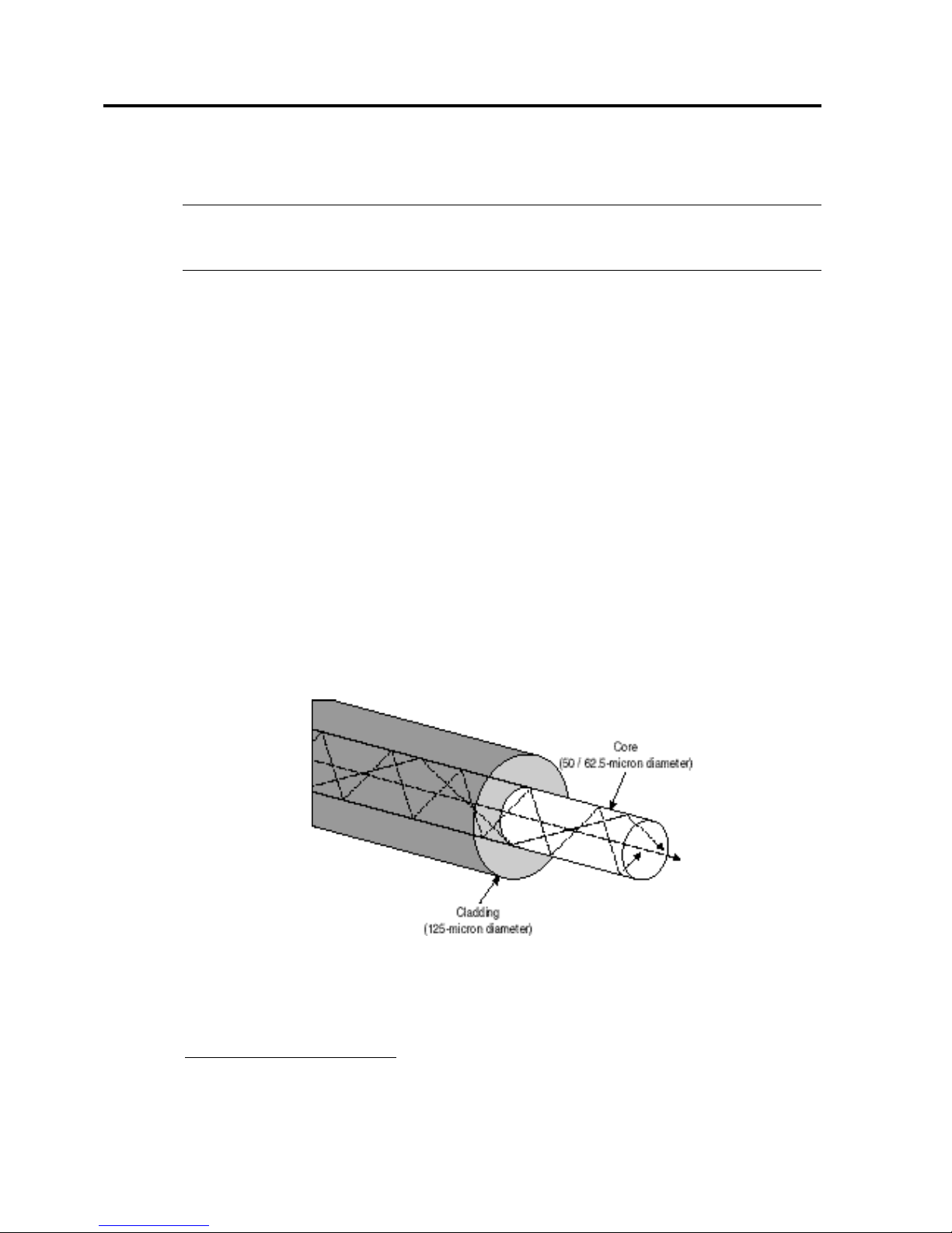
Optical fiber cable is categorized as either multi-mode3 or single-mode. In Figure 1, the diameter
of a multi-mode fiber is large enough to allow multiple streams of light to travel on different
paths from the transmitter to the receiver. Shortwave lasers are used with multi-mode fiber to
transmit data up to 500 meters.
Figure 1. Multi-mode fiber cable
2
Laser technology uses fiber optic media only.
3
Mode means path.
Page 4
Understanding Compaq StorageWorks RAID Array 4000 and Infrastructure Cabling 4
ECG02030699A
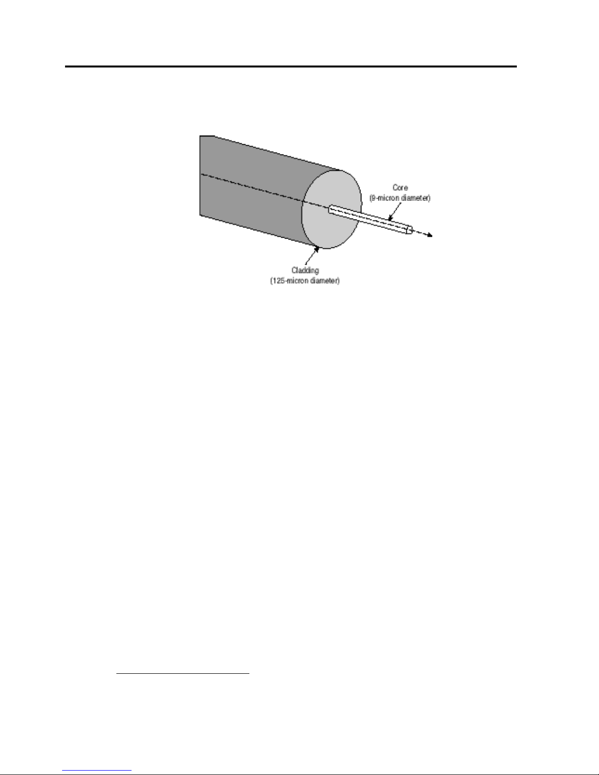
In Figure 2, the small diameter of a single-mode fiber allows one coherent stream of light to
travel along a single path. Longwave lasers are used with single-mode fiber to transmit data up to
10 kilometers.
Figure 2. Single-mode fiber cable
Understanding Fiber Types
Types of fibre channel media4 include:
• 62.5-micron multi-mode.
• 50-micron multi-mode.
• 9-micron single-mode.
4
The fiber types are distinguishable by their data transmission rates and distance capabilities.
Page 5

Understanding Compaq StorageWorks RAID Array 4000 and Infrastructure Cabling 5
ECG02030699A
Distance Limitations
Two factors that can limit the distance between the components are:
1. The data transmission rate—as shown in Table 1, the distance between the components of
each fiber type tends to decrease as the data transmission rate increases.
2. The degree of attenuation—attenuation is the reduction of the signal strength during
transmission from point to point. In this case, it is the light passing through the optic media.
The number of connectors and splices used to connect components affects the distance that
can exist between components.
Table 1. Data transmission rates and distance capabilities of fiber types
Transmission Rate
Supported by
Compaq
62.5-micron 50-micron 9-micron
100 MB/s
5
Yes 300 m 500 m 10 km
200 MB/s Future
6
150 m 300 m 2 km
400 MB/s Future 90 m 150 m 2 km
Formulas used to calculate the distance limitations are based on the data transmission rates and
the degree of attenuation. A company that provides fiber products and installation and testing
services can help determine distance capabilities and limitations for a particular installation. See
Acknowledgements and References later in this document.
Connection Components
To build a storage system that uses fibre channel technology, it is necessary to understand the use
and function of, hubs, gigabit interface converters (GBICs), and fibre channel cables and
connectors.
• Hubs allow of different GBIC types to be mixed so there can be different cable types within a
fibre channel topology. Hubs use port bypass circuitry to keep a fibre channel loop topology
intact.
• GBICs convert electrical signals to optical signals and optical signals to electrical signals at
the point where fiber cables connect to copper-wired components (hubs, controller cards, and
host adapters).
• Fibre channel cables and connectors join system components and connect to infrastructure
cabling.
5
Megabytes per second
6
A 200 MB/s transmission rate may be passed over in favor of a 400 MB/s transmission rate.
Page 6

Understanding Compaq StorageWorks RAID Array 4000 and Infrastructure Cabling 6
ECG02030699A
Hubs
Hubs provide the ability to use different fibre channel cables in the same loop to accommodate
different types of infrastructure cabling. Figure 3 shows an example of a 62.5-micron multi-mode
cable, a 50-micron multi-mode cable, and a 9-micron single-mode cable used in the same loop.
The hub’s ability to detect and bypass non-operational ports keeps the loop intact.
Figure 3. Using a hub to intermix fiber types
Gigabit Interface Converters
These industry-standard connection devices hot plug into all Fibre Channel System components
(host controllers, cables, hubs, and arrays). A shortwave GBIC (GBIC-SW) must be used with a
multi-mode fibre channel cable and a long wave GBIC (GBIC-LW) must be used with a
single-mode fibre channel cable.
A GBIC:
• Converts electrical signals into optical signals.
• Converts optical signals into electrical signals.
• Provides a transmission rate of 100 MB/s in each direction.
A GBIC-SW provides a transmission distance between components of up to 500 meters using
50-micron, multi-mode fiber optic cable. A GBIC-LW provides a transmission distance between
components of up to 10 kilometers using 9-micron, single-mode fiber optic cable.
Page 7

Understanding Compaq StorageWorks RAID Array 4000 and Infrastructure Cabling 7
ECG02030699A
A label describes the GBIC and distinguishes it as shortwave or long wave. The description may
spell out a GBIC’s characteristics or it may use the Fibre Channel Standard convention for
labeling. The labeling convention is SPEED-MEDIA-TRANSMITTER-DISTANCE.
An example of a GBIC label is 100-M5-SN-I. Use Table 2 to decode the example label as
follows:
• 100 means a bandwidth of 100 MB/s.
• M5 means 50-micron multi-mode cable.
• SN means shortwave laser without OFC.
• I means intermediate distance.
Table 2. Fibre Channel Standard convention for GBIC labeling
Speed 100 = 100 MB/s* 200 = 200 MB/s 400 = 400 MB/s
Media SM = 9-micron single-mode M5 = 50-micron multi-mode M6** = 62.5-micron multi-mode
Transmitter LL = long wave laser
(1300 nanometers)
SL = shortwave laser with OFC
(850 nanometers)
SN = shortwave laser without
OFC (850 nanometers)
Distance L = long distance (2 m to 10 km) I = Intermediate distance (2 m to
500 m)
S = short distance (2 m to
300 m)
* 1063 MBd is the data rate measured in megabaud and is equivalent to 106.3 MB/s, or 100 MB/s nominally.
** A cable labeled M6 can be used with an M5 GBIC.
*** Compaq only supports shortwave lasers without open fiber control (OFC), the SN version. OFC limits the amount
of light transmitted when the fiber connection is broken to prevent eye injury. Improvements in laser control
technology have eliminated the need for OFC.
Fibre Channel Cables and Connectors
Typically, fibre channel cables are a pair of fibers with connectors on each end. The fibers in a
fibre channel cable cross so that the input at one end of the fibre channel cable becomes the
output at the other end. The connectors are keyed to ensure that the connections are properly
oriented.
Compaq supplies 50-micron, multi-mode fibre channel cables in fixed lengths of 2 meters,
5 meters, 15 meters, 30 meters, and 50 meters. Compaq RA4000 storage system components ship
standard with 50-micron, multi-mode fibre channel cables. Support for 62.5-micron, multi-mode
and 9-micron, single-mode fibre channel cables is also available.
Fibre channel cables that connect to infrastructure cabling must match the fiber type of the
infrastructure cabling. For example, if 62.5-micron, multi-mode infrastructure cabling connects to
a wall outlet, the cabling that runs from the server to that wall outlet must be 62.5-micron,
multi-mode cable.
Connecting 50-micron fibre channel cable to 62.5-micron fibre channel cable can cause severe
degradation of the optical signal. This can result in marginal operation or an unreliable
connection.
Cable assembly suppliers can provide custom combinations of cable length, connector type, and
fiber type to mate with infrastructure cabling. See Acknowledgments and References later in this
document for suppliers.
Page 8

Understanding Compaq StorageWorks RAID Array 4000 and Infrastructure Cabling 8
ECG02030699A
Fibre channel cable types are labeled at one-meter intervals on the cable. A fibre channel cable
labeled “50/125” indicates a 50 micron inner core with 125 micron outer cladding. Table 3
identifies the color coding for fibre channel cables.
Table 3. Standard fibre channel cable color codes
Size Color
62.5 micron Slate gray or orange
50 micron Orange
9 micron Yellow
Compaq RA4000 system components interconnect using 50-micron and 62.5-micron multi-mode
cables and 9-micron single-mode cables. However, Compaq only provides 50-micron multi-mode
cables with the product. Customers can acquire the other cable types from Compaq and other
sources. Refer to Acknowledgements and References later in this document.
Interconnecting System Components
This section discusses interconnecting primary storage system components using the RA4000.
Overview of System Components
The RA4000 uses the components described in Table 4.
Table 4. Compaq StorageWorks RAID Array 4000 components
Component Description
RA4000
An external storage cabinet that houses the RA4000 Controller and up to
twelve 1-inch or eight 1.6-inch SCSI disk drives (Wide-Ultra SCSI-3,
Fast-Wide SCSI-2, or Fast SCSI-2).
RA4000 Controller An intelligent fibre channel-to-SCSI array controller with 64 MB cache.
Optional RA4000 Redundant
Controller
A standby controller that takes over in the event a component or connection fails in a
redundant configuration that provides no single point of failure. The redundant
controller is an RA4000 Controller with redundancy support firmware.
Compaq StorageWorks Fibre
Channel Storage Hub 7
Supports up to 7 devices on a fibre channel arbitrated loop.
Compaq StorageWorks Fibre
Channel Storage Hub 12
Supports up to 12 devices on a fibre channel arbitrated loop.
Compaq StorageWorks Fibre
Channel Host Adapter/E
An EISA-to-Fibre Channel Host Adapter.
Compaq StorageWorks Fibre
Channel Host Adapter/P
A PCI-to-Fibre Channel Host Adapter.
GBIC-SW Converts optical signals (770 to 860 nanometers) into electrical signals and electrical
signals into optical signals. Allows point-to point connections for distances up to
500 m.
GBIC-LW Converts optical signals (1,270 to 1,355 nanometers) into electrical signals and
electrical signals into optical signals. Allows point-to-point connections for distances
up to 10 km.
Multi-mode Cable 2-m, 5-m, 15-m, 30-m, or 50-m 50-micron fiber optic cable. All cables are available as
separate options. For 62.5-micron fiber optic cable, refer to Acknowledgements and
References later in this document.
Single-mode Cable Refer to Acknowledgements and References later in this document.
Page 9

Understanding Compaq StorageWorks RAID Array 4000 and Infrastructure Cabling 9
ECG02030699A
RAID Array 4000 Configurations
This section discusses possible RA4000 configurations without infrastructure cabling. For
simplicity, only a few possible configurations will be discussed. For more information on fibre
channel technology, refer to the Compaq website:
www.compaq.com/products/storageworks/
Single-Server Environments
In single-server environments, it is possible to connect the server directly to the RA4000.
In many cases, the server, the hub, and the storage arrays are located close to each other, making
interconnections easy to configure without using infrastructure cabling.
In Figure 4, the Fibre Channel Host Adapter connects to a Storage Hub 7. The Storage Hub 7
connects to three RA4000s. GBICs are installed at all fiber interconnections. There is no
redundancy to protect the data in this configuration should a component fail.
Using custom-length, 50-micron fiber, interconnect distances between components can be up to
500 meters. Therefore, RA4000s can be located up to 1 kilometer from the Fibre Channel Host
Adapter.
Using custom-length, 9-micron fiber, interconnect distances between components can be up to
10 kilometers. Therefore, RA4000s can be located up to 20 kilometers from the Fibre Channel
Host Adapter.
Figure 4. Single server and single controller RA4000s
Page 10

Understanding Compaq StorageWorks RAID Array 4000 and Infrastructure Cabling 10
ECG02030699A
The RA4000 brings no single point of failure (NSPOF) functionality to workgroup and
departmental servers with optional redundant array controllers and failover software. In a
redundant configuration, if the active controller or other component fails or becomes inoperative,
the standby controller will take over, notify the system administrator of the problem, and maintain
operation of the storage subsystem.
Figure 5 shows the minimum hardware requirements for a single server and single RA4000 with
NSPOF.
Figure 5. Single server and redundant controller configuration
Clustered Server Environments
Figure 6 shows a clustered configuration without NSPOF.
Figure 6. Single controllers in a clustered configuration
Page 11

Understanding Compaq StorageWorks RAID Array 4000 and Infrastructure Cabling 11
ECG02030699A
Figure 7 shows a clustered server environment with NSPOF.
Figure 7. Redundant controllers in a clustered configuration
Since many enterprises’ storage components are located across greater distances, the servers are
connected through single-mode cabling.
Using Infrastructure Cabling
Infrastructure cabling (or cable plant) refers to the complete cabling system within a building or
buildings. This section discusses of infrastructure cabling and includes a scenario in which an
RA4000 uses infrastructure cabling to connect across multiple floors. This example should help
answer the questions:
• Is the existing infrastructure cabling useable?
• Does new infrastructure cabling need to be installed?
• If new infrastructure cabling is needed, what type should be installed?
Page 12

Understanding Compaq StorageWorks RAID Array 4000 and Infrastructure Cabling 12
ECG02030699A
Typical Fiber Infrastructure Cabling Scheme
Figure 8 shows a fiber infrastructure-cabling scheme across three floors. A fibre channel cable
(or a patch cable) connects servers to work area outlets. Horizontal fiber cable connects work area
outlets to telecommunications closets. In the telecommunications closets, horizontal and
backbone cables interconnect through fibre channel patch panels. The fiber backbone cable
connects telecommunications closets to the main distribution center.
Figure 8. Infrastructure cabling across three floors
Page 13

Understanding Compaq StorageWorks RAID Array 4000 and Infrastructure Cabling 13
ECG02030699A
Compaq StorageWorks RAID Array 4000 Using
Infrastructure Cabling
Consider the scenario in which the server is located several floors away from its storage:
A server is located in the telecommunications closet on the nth floor of a building and will connect
to a hub and storage arrays located in the basement. Connecting the server to the hub requires
infrastructure cabling. What type of infrastructure cabling will work?
To select an appropriate fiber type, measure the length of the backbone cable and determine the
data transmission rate. Remember, data transmission rates and attenuation limit distance
capability.
Table 5. Appropriate fibre channel cable type at 100 MB/s
Distance between components Use
≥0 m and ≤ 300 m
á
62.5, 50, or 9 micron fiber
≥200 m and ≤ 500 m
á
50 or 9 micron fiber
≥500 m and ≤ 10 km
á
9 micron fiber
Using Existing Cabling or Installing New Cabling
If you determine that 62.5 micron fiber will support your configuration and you have 62.5 micron
installed in the building, you can use the existing fiber.
Note: Compaq does not require that the bandwidth of all cables be measured. Measurement of
existing fiber only needs to be done if the bandwidth value is unknown.
The manufacturer measures the bandwidth of new fiber. Therefore, a bandwidth measurement is
not necessary for new fiber for which the bandwidth is already known.
Be sure to consider any plans for expanding the system and using increased data transmission
rates. To support expansion and increased data transmission rates, 50 micron fiber or 9 micron
fiber may be required.
If you have no fiber cable installed in the building, Compaq recommends that you use 50 micron
fiber. The primary standard for fibre channel connections is 50 micron fiber which allows
flexibility for system expansion and supports faster data transmission rates across greater
distances.
If you have no fiber installed, or if 62.5 micron does not satisfy distance requirements, the choice
between 50 micron and 9 micron fiber depends on current and future configuration requirements
and the use of faster data transmission rates.
Page 14

Understanding Compaq StorageWorks RAID Array 4000 and Infrastructure Cabling 14
ECG02030699A
Testing
Testing ensures proper operation and reduces the error rate.
The power generated by the transmitter and the sensitivity of the receiver determine the amount
of power available. This amount must be greater than the sum of any power penalties and the
attenuation between the optical transmitter and receiver.
Attenuation will always occur in the fiber, connectors, and splices. A variety of factors can cause
excessive attenuation, and testing detects excessive attenuation between components.
For example, a splice will always cause some amount of attenuation, but a poorly joined splice
may cause attenuation that exceeds expectations. Bad connections can be detected and repaired
during testing.
Individuals experienced in testing and installing fiber optic infrastructure cabling should test
cabling for the link insertion loss after installation. Testing existing infrastructure cabling can be
difficult because portable bandwidth test equipment may not be available. For more information,
see Acknowledgments and References later in this document.
Test Specifications
Multi-mode cables should be tested such that the total link insertion loss from the transmitter to
the receiver is no greater than 6 dB minus any associated power penalties. EIA/TIA-526-14,
Method B can be used for insertion loss testing.
The modal bandwidth requirement for 62.5-micron multi-mode cables is 160 MHz·km at 850 nm.
The fiber must comply with the appropriate Fiber Optic Test Procedure (FOTP-30, FOTP-51,
FOTP-54) for testing multi-mode cable bandwidth as supplied by the fiber manufacturer. The
length (62.5/125 optical cable) is limited by the bandwidth of the cable. A larger core size cable
results in higher modal dispersion, producing a lower bandwidth, and limits the length to shorter
distances between components.
The modal bandwidth requirement for 50-micron multi-mode cables is 500 MHz·km at 850 nm as
tested by the fiber manufacturer. This higher modal bandwidth results in longer achievable
distances between components, compared to 62.5 micron multi-mode cables, for a given
data rate.
Page 15

Understanding Compaq StorageWorks RAID Array 4000 and Infrastructure Cabling 15
ECG02030699A
Handling Fiber and Fiber Connectors
Observe the following guidelines for handling fiber and fiber connectors:
• Protect optical components from heat, contaminants, abrasion, excessive differential or lateral
movement, and mechanical hazards.
• Avoid kinking or small-bend radii of the fiber. The rule of thumb is that the bend radius
should be greater than 10 times the outside diameter of the cable. For Compaq-supplied fibre
channel cables, the bend radius is 30 milimeters, or 1.25 inches.
• Do not place heavy objects or other heavier cables on top of fiber cable. These objects can
deform the fiber.
All of these factors can reduce the amount of light passing through a cable or connection and can
degrade performance.
GBICs and fibre channel cables ship with dust caps installed and these caps should remain
installed until an optical connection is made. Reinstall the dust caps whenever cables and
connectors are detached.
Compaq products ship with instructions for making proper connections. Clean a connection any
time it may have been exposed to dust or when there is any doubt about its cleanliness.
Acknowledgments and References
Compaq would like to thank Alcoa Fujikura, Ltd. (www.alcoa.com) and Siecor
(www.siecor.com) for their contributions to this paper. Both companies provide fiber products
and installation and testing services.
For Compaq supplied fibre channel products refer to the following two sites:
• www.compaq.com
• www.compaq.com/products/storageworks/
Other companies that provide fiber products and installation and testing services are listed in the
Fibre Channel Community Web pages:
www.fcloop.org/vlist/default.asp
 Loading...