

Page 1

FOREWORD
Notice
The information in this guide is subject to change without notice.
COMPAQ COMPUTER CORPORATION SHALL NOT BE LIABLE FOR TECHNICAL OR EDITORIAL
ERRORS OR OMISSIONS CONTAINED HEREIN; NOR FOR INCIDENTAL OR CONSEQUENTIAL
DAMAGES RESULTING FROM THE FURNISHING, PERFORMANCE, OR USE OF THIS MATERIAL.
This guide contains information protected by copyright. No part of this guide
may be photocopied or reproduced in any form without prior written consent
from Compaq Computer Corporation.
1990 Compaq Computer Corporation.
All rights reserved. Printed in the USA.
COMPAQ, DESKPRO, Registered United States Patent and Trademark Office.
SYSTEMPRO is a trademark of Compaq Computer Corporation.
The software described in this guide is furnished under a license agreement or
nondisclosure agreement. The software may be used or copied only in
accordance with the terms of the agreement.
Product names mentioned herein may be trademarks and/or registered trademarks
of their respective companies.
MAINTENANCE AND SERVICE GUIDE
COMPAQ SLT 386s/20 PERSONAL COMPUTER,
COMPAQ SLT/286 PERSONAL COMPUTER
First Edition (June 1990)
Text PN 118385-001
Preface
THE MAINTENANCE AND SERVICE GUIDE COMPAQ SLT 386s/20 PERSONAL COMPUTER,
COMPAQ SLT/286 PERSONAL COMPUTER is a troubleshooting guide. It can be used
as a reference when servicing the COMPAQ SLT 386s/20, Model 60 and Model 120,
or the COMPAQ SLT/286, Model 20 and Model 40. Compaq Computer Corporation
reserves the right to make changes to the computers without notice. The
diagrams and procedures in this document apply to these computers. Diagnostic
tests are designed to test only these products.
Interpreting Symbols
WARNING: TEXT SET OFF IN THIS MANNER INDICATES THAT FAILURE TO FOLLOW
DIRECTIONS IN THE WARNING COULD RESULT IN BODILY HARM OR LOSS OF LIFE.
CAUTION: TEXT SET OFF IN THIS MANNER INDICATES THAT FAILURE TO FOLLOW
DIRECTIONS COULD RESULT IN DAMAGE TO EQUIPMENT OR LOSS OF DATA.
IMPORTANT: Text set off in this manner presents clarifying information or
specific instructions.
NOTE: Text set off in this manner presents commentary sidelights, or
interesting points of information.
Locating Additional Information
Page 2

The following documentation is available for the COMPAQ SLT 386s/20 and
COMPAQ SLT/286 Personal Computers:
o OPERATIONS GUIDE
o TECHNICAL REFERENCE GUIDE
o MAINTENANCE AND SERVICE GUIDE - OPTIONS AND PERIPHERALS
o MAINTENANCE AND SERVICE GUIDE - SUPPORT SOFTWARE
o MS-DOS REFERENCE GUIDE
o MS OS/2 COMMAND REFERENCE AND USER'S GUIDE
o BASIC REFERENCE GUIDE
o COMPAQ SERVICE QUICK REFERENCE GUIDE
o COMPAQ Service Advisories and Bulletins
o HOW TO DO BUSINESS WITH COMPAQ CUSTOMER SERVICE
Technician Notes
CAUTION: ONLY AUTHORIZED TECHNICIANS TRAINED BY COMPAQ SHOULD ATTEMPT TO
REPAIR THIS EQUIPMENT. ALL TROUBLESHOOTING AND REPAIR PROCEDURES ARE DETAILED
TO ALLOW ONLY SUBASSEMBLY/MODULE LEVEL REPAIR. BECAUSE OF THE COMPLEXITY OF
THE INDIVIDUAL BOARDS AND SUBASSEMBLIES, NO ONE SHOULD ATTEMPT TO MAKE REPAIRS
AT THE COMPONENT LEVEL OR TO MAKE MODIFICATIONS TO ANY PRINTED WIRING BOARD.
IMPROPER REPAIRS CAN CREATE A SAFETY HAZARD. ANY INDICATIONS OF COMPONENT
REPLACEMENT OR PRINTED WIRING BOARD MODIFICATIONS MAY VOID ANY WARRANTY OR
EXCHANGE ALLOWANCES.
Page 3

Chapter 1 - Specifications
INTRODUCTION
This chapter provides physical, environmental, and performance specifications
for the following COMPAQ SLT 386s/20 Personal Computer and the COMPAQ SLT/286
Personal Computer subsystems:
o System Unit
o Laptop Enhanced Keyboard
o VGA Backlit Display
o 3 1/2 Inch 1.44 Megabyte Diskette Drive
o Fixed Disk Drives
o Internal Power Supply
o AC Adapter
o Battery Pack
Chapter 1.1 SYSTEM UNIT
==============================================================================
Dimensions:
Height 4.15 in. 10.54 cm
Depth 8.50 in. 29.59 cm
Width 13.50 in. 34.29 cm
Weight:
COMPAQ SLT 386s/20 Personal
Computer:
Page 4

Model 120 14.0 lb 6.30 kg
Model 60 14.0 lb 6.30 kg
COMPAQ SLT/286 Personal Computer:
Model 40 14.0 lb 6.30 kg
Model 60 14.0 lb 6.30 kg
Standalone (Battery) Power
Requirements:
Nominal Operating Voltage 12 VDC 12 VDC
Average Power 8.0W 8.0W
Peak Power 11.0W 11.0W
Environmental Requirements:
Temperature Range:
Operating 50oF to 95oF 10oC to 35oC
Nonoperating -4oF to 140oF -20oC to 60oC
Relative Humidity (noncondensing):
Operating 10% to 90% 10% to 90%
Nonoperating 5% to 95% 5% to 95%
Shock and Vibrations:
Shock 40 g, 11 ms, half sine (nonoperating)
Vibration 3 g, 5 - 500 Hz 1/2 octave/minute sweep
2 hour duration (nonoperating)
1 g, 5 - 500 Hz (operating)
Maximum Unpressurized Altitude:
Operating 10,000 ft 3048 m
Nonoperating 40,000 ft 12192 m
==============================================================================
Chapter 1.2 LAPTOP ENHANCED KEYBOARD
==============================================================================
Dimensions:
Height 0.65 in. 1.65 cm
Depth 6.45 in. 16.38 cm
Width 13.50 in. 34.29 cm
Weight 1.38 lb 0.63 kg
Number of Keys 82 or 83 82 or 83
Cable:
Compressed 6.50 in. 16.51 cm
Extended 24.00 in. 60.96 cm
Interface 6 pin mini DIN 6 pin mini DIN
connector connector
Power:
Volts 5 VDC 5 VDC
Current 50 mA maximum 50 mA maximum
20 mA nominal 20 mA nominal
==============================================================================
Page 5

Chapter 1.3 VGA BACKLIT DISPLAY
==============================================================================
Dimensions (image area):
Height 5.86 in. 14.88 cm
Depth 0.90 in. 2.30 cm
Width 7.81 in. 19.84 cm
Diagonal Size 10.00 in. 25.40 cm
Mounting Internal Internal
Display Compensated Compensated
Cable:
Diameter 0.28 in. 0.71 cm
==============================================================================
Supertwist LCD Supertwist LCD
Chapter 1.4 DISKETTE DRIVE
==============================================================================
-----------------------------------------------------------------------------Diskette Size 3 1/2 inch
LED Indicators:
Read/Write (high density) Green
Read/Write (low density) Orange
Capacity Per Diskette (high/low) 1.44 MB/720 Kbytes
Drives Supported Two
Drive Height Third
Drive Rotation (rpm) 300
Transfer Rate (bps) (high/low) 500K/250K
Bytes Per Sector 512
Sectors Per Track (high/low) 18/9
1.44 MEGABYTE
Tracks Per Side (high/low) 80/80
Access Times:
Track to Track (ms) 3
Average (ms) 79
Settling Time (ms) 15
Latency Average (ms) 100
Cylinders (high/low) 80/80
Page 6

Read/Write Heads 2
==============================================================================
Chapter 1.5 FIXED DISK DRIVES
COMPAQ SLT 386s/20 Personal Computer
==============================================================================
-----------------------------------------------------------------------------Standard Configurations Model 120 Model 60
LED Indicators Orange Orange
Formatted Capacity Per Drive 121.56 MB 60.7 MB
Drives Supported One One
Drive Height Third Third
Drive Size 3 1/2 inch 3 1/2 inch
Drive Type 50 55
Transfer Rate (Mb/s) 12 12
Sector Interleave 1:1 1:1
120 MEGABYTE 60 MEGABYTE
Bytes Per Sector 512 512
Sectors Per Track:
Physical 40 39
Logical 39 39
-----------------------------------------------------------------------------120 MEGABYTE 60 MEGABYTE
------------------------------------------------------------------------------
Number of Surfaces:
Physical 2 2
Logical 4 4
Tracks per Surface 1053 636
Access Times (including settling):
Track to Track (ms) <5 <5
Average (ms) <19 <19
Maximum (ms) <35 <35
Physical Cylinders 1522 1522
Physical Read/Write Heads 4 2
Logical Cylinders 760 760
Logical Read/Write Heads 8 4
==============================================================================
Page 7

COMPAQ SLT/286 Personal Computer
==============================================================================
40 MEGABYTE 20 MEGABYTE
------------------------------------------------------------------------------
Standard Configurations Model 40 Model 20
LED Indicators Orange Orange
Formatted Capacity Per Drive 42.9 MB 21.4 MB
Drives Supported One One
Drive Height 1 inch 1 inch
Drive Size 3 1/2 inch 3 1/2 inch
Drive Type 22 2
Transfer Rate (Mb/s) 12 10
Sector Interleave 1:1 3:1
Bytes Per Sector 512 512
Sectors Per Track:
Physical 40 33
Logical 17 40
-----------------------------------------------------------------------------40 MEGABYTE 20 MEGABYTE
------------------------------------------------------------------------------
Number of Surfaces:
Physical 2 2
Logical 4 4
Tracks per Surface 1053 636
Access Times (including settling):
Track to Track (ms) 8 8
Average (ms) 29 29
Maximum (ms) 50 50
Physical Cylinders 1053 636
Physical Read/Write Heads 2 2
Logical Cylinders 524 615
Logical Read/Write Heads 4 4
==============================================================================
Chapter 1.6 INTERNAL POWER SUPPLY
==============================================================================
Input Requirements:
Page 8

Input Voltage 10 - 18.2 VDC
Input Fuse 5A (Not user accessible)
------------------------------------------------------------------------------
Power Output:
Steady State 18W
Peak 23W
------------------------------------------------------------------------------
Cooling Convection
------------------------------------------------------------------------------
VDC Output:
Nominal
Continuous Maximum
Nominal Current Current Peak Regulation
Voltage Minimum Maximum Current Tolerance
-----------------------------------------------------------------------------+ 5.00 0A 2A 3A ñ 3%
+ 12.00 0A 0.6A 1A ñ 8%
- 13.00 0A 60 mA 60 mA ñ 15%
- 26.00 0A 60 mA 60 mA ñ 15%
==============================================================================
Chapter 1.7 AC ADAPTER
==============================================================================
Dimensions:
Height 2.40 in. 6.10 cm
Depth 8.60 in. 21.84 cm
Width 3.40 in. 8.64 cm
Weight 1.66 lb 0.75 kg
Power Supply:
Operating Voltage 110 VAC/220 - 240 VAC
Steady State Power 20W
Peak Power 33W
Operating Current 1.0A
Frequency 50/60 Hz
==============================================================================
Chapter 1.8 BATTERY PACK
==============================================================================
Dimensions:
Height 1.20 in. 3.05 cm
Depth 5.40 in. 13.72 cm
Width 4.60 in. 11.68 cm
Weight 1.97 lb 0.89 kg
Power Supply:
Nominal Open Circuit Voltage 12.0 VDC
Capacity 2.4A
Power 29W
==============================================================================
Page 9

Chapter 2 - Power On Self Test (POST)
INTRODUCTION
This chapter lists the subassemblies checked by the Power On Self Test (POST)
and briefly describes the types of error codes that can occur. The chapter
also includes problem isolation procedures and a flowchart for quick
reference.
Chapter 2.1 POST
POST is a series of diagnostic tests that runs automatically on the
COMPAQ SLT 386s/20 and COMPAQ SLT/286 Personal Computers when the computers
are turned on.
POST checks the following subassemblies to ensure that the computer system is
functioning properly:
o System Board
o System Memory
o Memory Boards
o Keyboard
o Controller Circuitry
o VGA Backlit Display (Monitor)
o Fixed Disk Drives
o Diskette Drives
POST also detects the type of mass storage devices installed in the computer.
If POST finds an error in the computer, an error condition is indicated by an
audible and/or visual message. See Chapter 3, "Error Messages and Codes," for
an explanation of the error codes and a recommended course of action.
Chapter 2.2 PRELIMINARY STEPS
If you encounter an error condition, complete the following steps before
starting the problem isolation procedures:
1. Turn off power to the computer. Do not remove the battery pack.
2. Disconnect any external devices (leave the AC Adapter attached). Do not
disconnect the printer if you want to test the printer or use it to log
error messages.
3. Install all appropriate loopback plugs and terminating plugs for complete
testing.
4. Clear the power on password, if it is preset by the user.
NOTE: The COMPAQ SLT 386s/20 has a power on password feature. You will
know that the power on password is set when a key icon (o--m) appears
Page 10

on the screen when POST completes. If this occurs, you must enter the
password to continue.
If you do not have access to the password, you must disable the power on
password feature by resetting the password switch on the system board (see
section 2.3, "Clearing Power On Password").
5. Position the brightness and contrast controls approximately in the center
of their range.
6. Insert the DIAGNOSTICS diskette into drive A.
7. Turn on the computer.
8. Follow the procedures of the Problem Isolation Flowchart in section 2.4.
Refer to Chapter 3, "Error Messages and Codes," for detailed information on
problem isolation.
Chapter 2.3 CLEARING POWER ON PASSWORD
To clear the power on password feature on the COMPAQ SLT 386s/20, disable the
power on password by resetting the system board switch. To do so, complete
the following steps:
1. Disconnect the AC power.
2. Disassemble the computer to reach the system board (refer to Chapter 5).
3. Locate switch SW1 on the system board (Figure 2-1).
4. Change switch SW1-2 to the ON position (disable).
5. Reassemble the computer (refer to Chapter 5); then reconnect the AC power.
6. Turn on the computer and allow it to complete POST. If the key icon
(o--m) does not appear when POST completes, the power on password has
been cleared.
To reset or enable the power on password switch, follow these steps:
1. Turn off the computer and disconnect the AC power.
2. Disassemble the computer to reach the system board (refer to Chapter 5).
3. Reset switch SW1-2 to the OFF position (enable).
4. Reassemble the computer.
5. Reconnect the AC power and turn on the computer.
IMPORTANT: If the power on password switch is not reset to its original
position, it will be impossible to reestablish the password.
Page 11
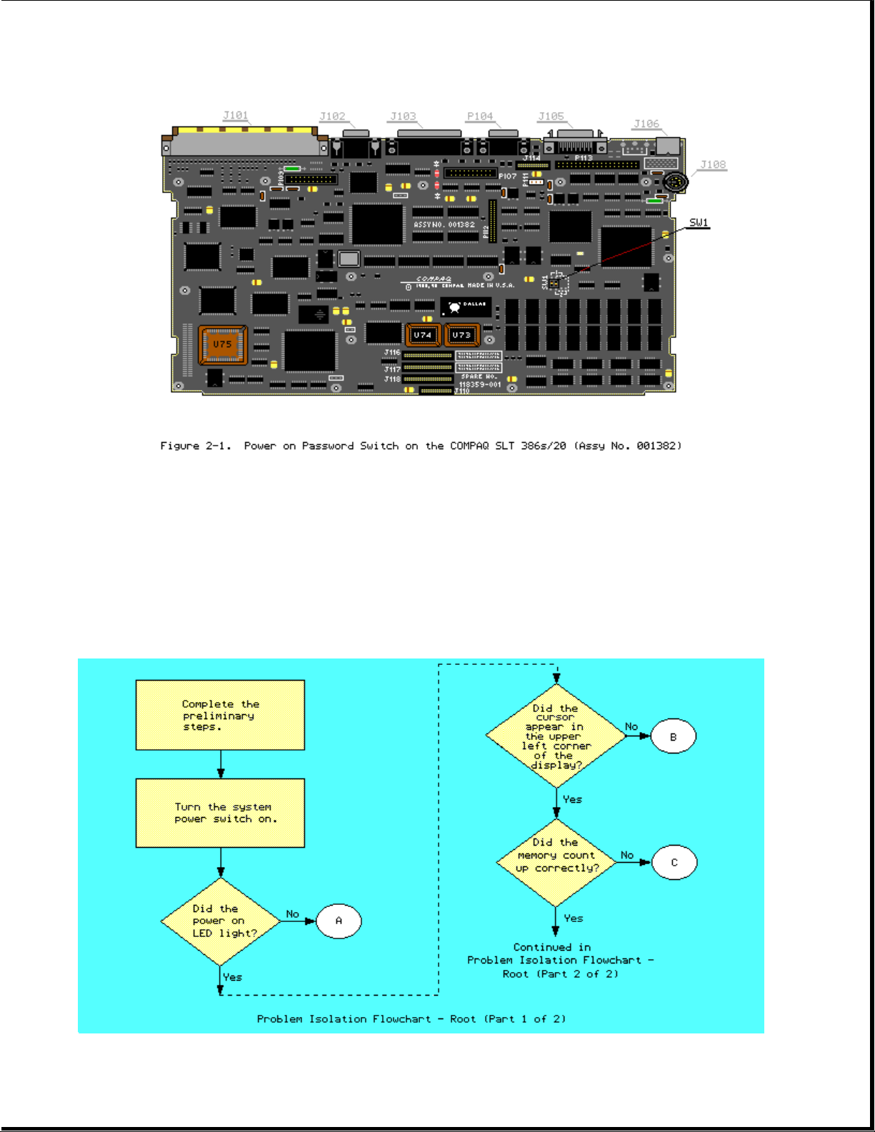
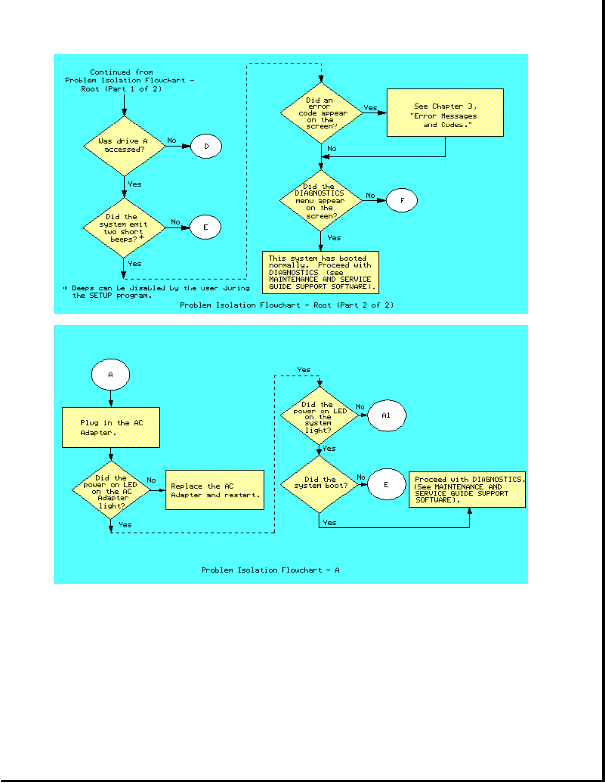
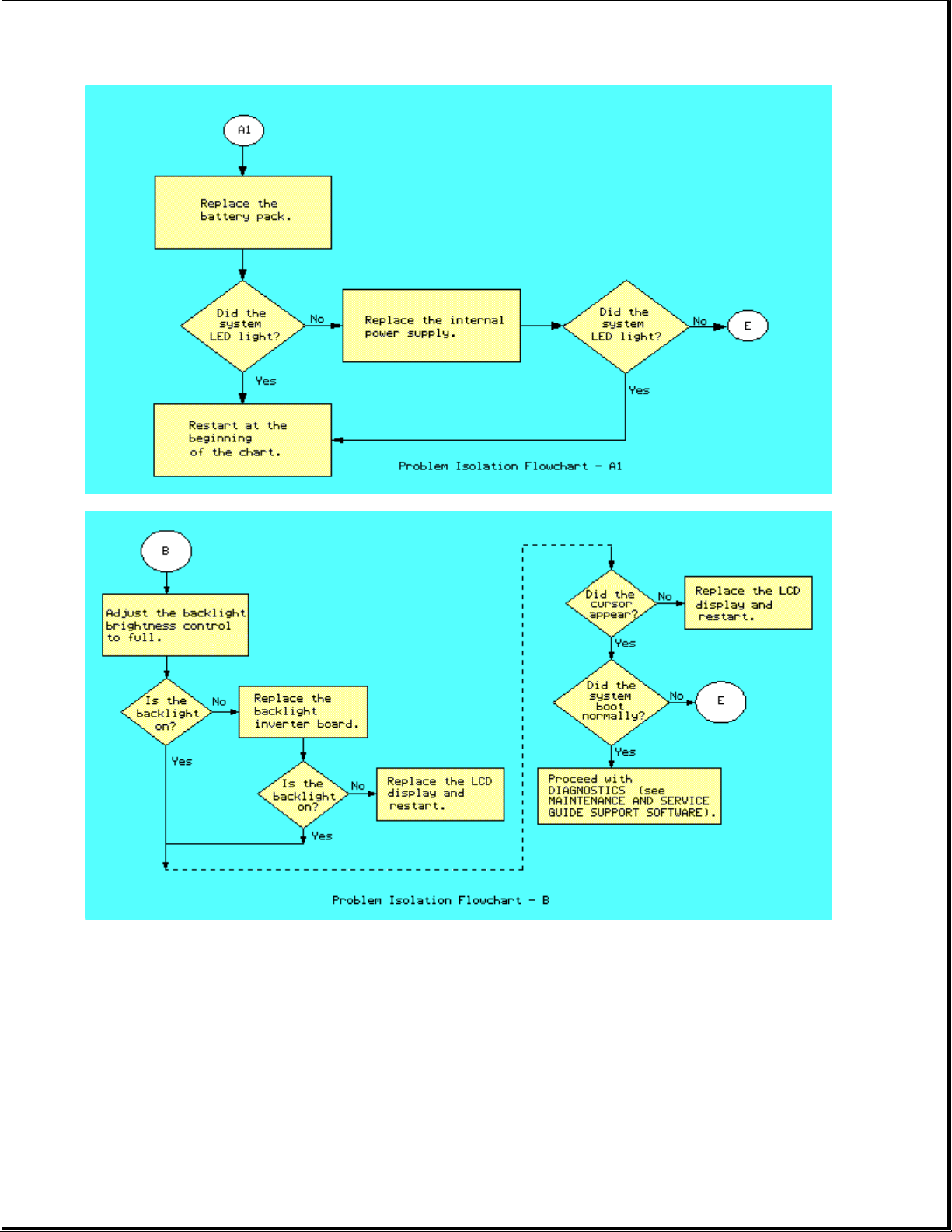
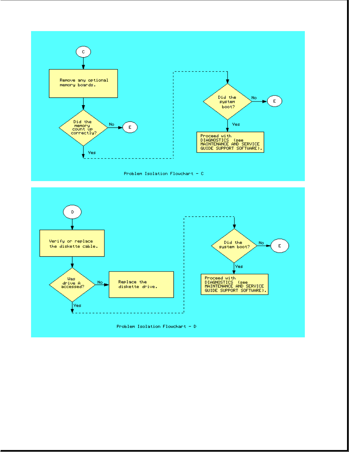
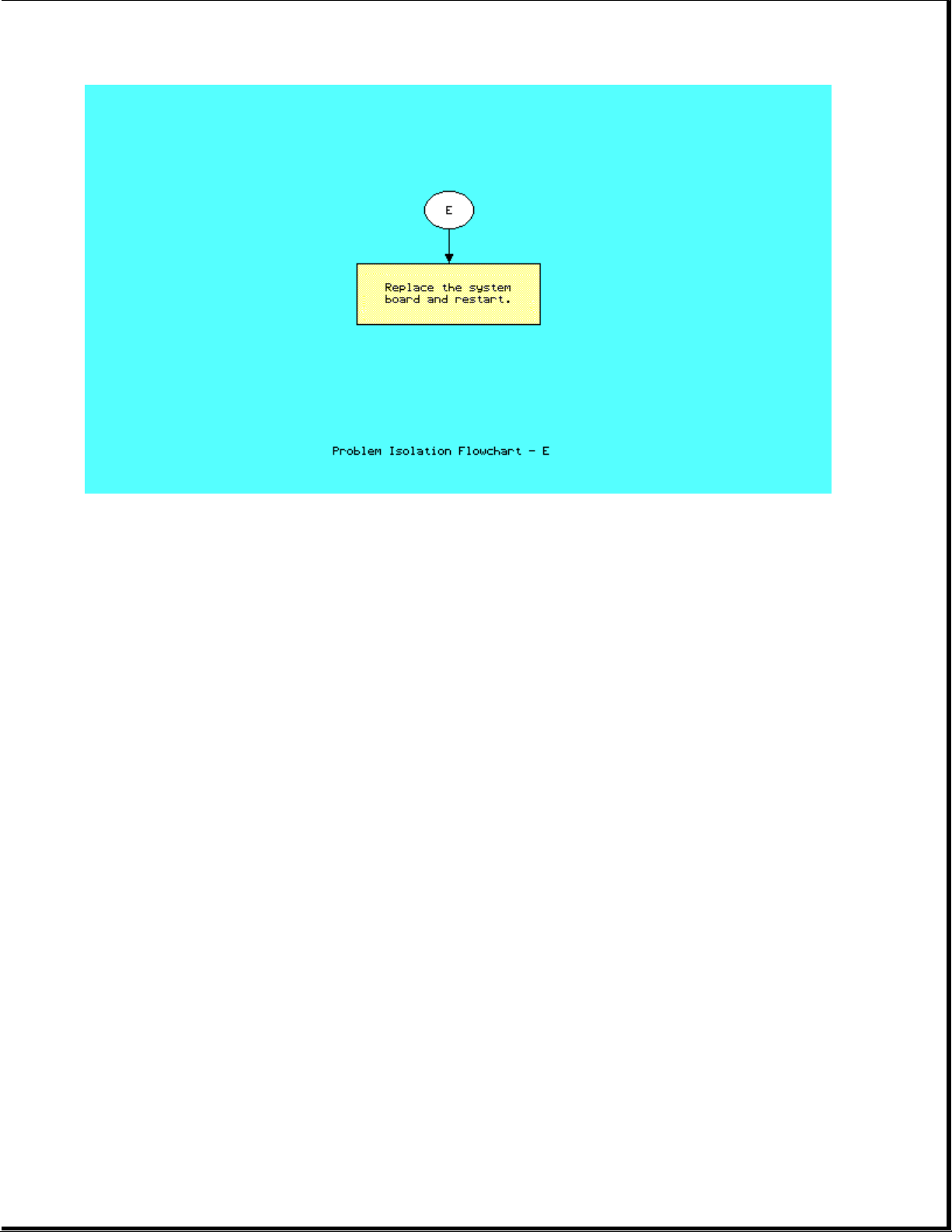
Chapter 2.4 PROBLEM ISOLATION FLOWCHART
The problem isolation flowchart provides a quick reference for identifying and
correcting problems that may occur during POST. The flowchart gives
troubleshooting procedures for identifying malfunctions. It also directs you
to the DIAGNOSTICS chapter in the MAINTENANCE AND SERVICE GUIDE SUPPORT
SOFTWARE and to Chapter 3, "Error Messages and Codes," for more detailed
troubleshooting information.
Page 12
Page 13
Page 14
Page 15
Page 16

Chapter 3 - Error Messages and Codes
INTRODUCTION
This chapter contains Power On Self Test (POST) messages, DIAGNOSTIC error
codes, and memory error codes.
The messages and codes appear in tables that list the message or error code, a
description of the error or its probable cause, and the action recommended to
resolve the error condition.
Chapter 3.1 POWER ON SELF TEST MESSAGES
An error message results if a problem is encountered during POST, which runs
automatically when the system is turned on.
Table 3-1 lists the messages for POST, the audible (beep) messages, probable
causes, and recommended actions.
Table 3-1. Power On Self Test Messages
==============================================================================
Message Beeps Cause Action
-----------------------------------------------------------------------------101 - ROM Error 1 Long, System ROM 1. Inspect the ROM
1 Short placement.
-----------------------------------------------------------------------------101 - I/O ROM Error 1 Long, System ROM 1. Inspect the ROM
1 Short placement.
-----------------------------------------------------------------------------102 - System Board None System board Replace the system
or System Memory board.
Failure
-----------------------------------------------------------------------------162 - System 2 Short Configuration Run SETUP.
Options Error error
-----------------------------------------------------------------------------162 - System Options 2 Short Configuration Run SETUP.
Not Set incorrect
-----------------------------------------------------------------------------163 - Time & Date 2 Short Invalid time Run SETUP.
Not Set or date in
------------------------------------------------------------------------------
Message Beeps Cause Action
-----------------------------------------------------------------------------164 - Memory 2 Short Configuration Run SETUP.
Probable Recommended
2. Verify the
correct ROM.
3. Replace the ROM.
2. Verify the
correct ROM.
3. Replace the ROM.
configuration
memory
Probable Recommended
Page 17

Size Error memory
incorrect
-----------------------------------------------------------------------------167 - RTC Lost 2 Short Real time Replace system
Power clock board.
-----------------------------------------------------------------------------XX000Y ZZ * None RAM failure 1. Replace the
201 - Memory Error memory board
(See Figure 3-1.)
2. Replace the
system board.
-----------------------------------------------------------------------------XX000Y ZZ * None RAM failure Replace the system
203 - Memory board.
Address Error
-----------------------------------------------------------------------------205 - Memory Error None Cache Memory Run DIAGNOSTICS.
error
-----------------------------------------------------------------------------301 - Keyboard Error None Keyboard Replace the
keyboard.
-----------------------------------------------------------------------------301 - Keyboard None Keyboard Replace the
Error or Test keyboard.
Fixture Installed
-----------------------------------------------------------------------------* See Section 3.3, Memory Error Codes
-----------------------------------------------------------------------------Probable Recommended
Message Beep Cause Action
------------------------------------------------------------------------------
303 - Keyboard None System board Replace the system
Controller Error keyboard board.
controller
------------------------------------------------------------------------------
304 - Keyboard or None Keyboard 1. Replace the
System Unit Error keyboard.
2. Replace the
system board.
-----------------------------------------------------------------------------401 - Printer None Printer Replace the system
Error controller board.
(COMPAQ SLT/286 only)
-----------------------------------------------------------------------------601 - Diskette None Diskette 1. Check and/or
Controller Error Controller replace cables.
circuitry 2. Run DIAGNOSTICS.
3. Replace the
system board.
-----------------------------------------------------------------------------605 - Diskette 2 Short Mismatch in Run SETUP.
Drive Error drive type
-----------------------------------------------------------------------------610 - External Storage None External Turn on External
Device Failure Storage Module Storage Module or
Hit F1 when ready attached but disconnect from
turned off computer.
-----------------------------------------------------------------------------702 - Coprocessor None Coprocessor 1. Run SETUP.
Page 18

Detection Error problem; added 2. Check the
or removed the coprocessor
coprocessor installation.
3. Replace the
coprocessor.
-----------------------------------------------------------------------------1125 - Internal Serial 2 Short Defective Replace the
Port Failure internal system board.
serial port
-----------------------------------------------------------------------------1150 - Comm Port 2 Short Added or Run SETUP.
Configuration Error removed modem,
or second
serial
interface
board
-----------------------------------------------------------------------------1780 - Disk 0 None Fixed disk 1. Run DIAGNOSTICS.
Failure drive/format 2. Replace the
error drive.
-----------------------------------------------------------------------------1781 - Disk 1 None Fixed disk 1. Run DIAGNOSTICS.
Failure drive/format 2. Replace the
error drive.
-----------------------------------------------------------------------------Probable Recommended
Message Beeps Cause Action
------------------------------------------------------------------------------
1782 - Disk None Fixed disk 1. Run DIAGNOSTICS.
Controller Failure drive 2. Replace the
controller drive.
error
------------------------------------------------------------------------------
1790 - Disk 0 None Fixed disk 1. Run DIAGNOSTICS.
Error drive error 2. Replace the
drive.
------------------------------------------------------------------------------
XX000Y ZZ Parity None Parity RAM Run DIAGNOSTICS.
Check 2 failure
------------------------------------------------------------------------------
Audible * 1 Short Power on None.
successful
------------------------------------------------------------------------------
Audible * 2 Short Power on None.
successful
------------------------------------------------------------------------------
(RESUME = "F1" KEY) None As indicated Press F1 key.
to continue
------------------------------------------------------------------------------
* Beeps can be disabled by the user during the SETUP program.
==============================================================================
Page 19

Chapter 3.2 DIAGNOSTIC ERROR CODES
DIAGNOSTIC error codes occur if the system recognizes a problem while running
the COMPAQ DIAGNOSTICS program (refer to the MAINTENANCE AND SERVICE GUIDE
SUPPORT SOFTWARE for additional information on running the DIAGNOSTICS
software). These error codes help identify possible defective subassemblies.
Tables 3-2 through 3-11 list possible error codes, a description of the error
condition, and the action required to resolve the error condition.
In each case, the Recommended Action column lists steps necessary to correct
the problem. After completing each step, run the DIAGNOSTICS program to
verify whether the error condition has been corrected. If the error code
reappears, perform the next step, then run the DIAGNOSTICS program again.
Follow this procedure until the DIAGNOSTICS program no longer detects an error
condition.
The error codes appear in an AYY-XX or AAYY-XX format.
A or AA = number that represents faulty assembly
YY = test or action that failed
XX = a specific problem
Example: Error code 610 - 21 shows that the diskette drive failed to get
change line status.
For assistance in the removal and replacement of a particular subassembly, see
Chapter 5, "Removal and Replacement Procedures."
Table 3-2. Processor Test Error Codes
==============================================================================
Error
Page 20

Code Description Recommended Action
------------------------------------------------------------------------------
101 - 01 CPU test failed Replace the system board and retest
for error code 101 - 01.
------------------------------------------------------------------------------
102 - 01 Coprocessor initial The following steps apply to
status word incorrect error codes 102 - xx:
102 - 02 Coprocessor initial control 1. Run SETUP.
word incorrect 2. Replace the coprocessor and
retest.
102 - 03 Coprocessor tag word not 3. Replace the system board and
all ones retest.
102 - 04 Coprocessor tag word not
all zeros
102 - 05 Coprocessor exchange
command failed
102 - 06 Coprocessor masked
exception incorrectly handled
102 - 07 Coprocessor unmasked exception
incorrectly handled
------------------------------------------------------------------------------
Error
Code Description Recommended Action
------------------------------------------------------------------------------
102 - 08 Coprocessor wrong mask bit set The following steps apply to
in status register error codes 102 - xx:
102 - 09 Coprocessor unable to store 1. Run SETUP.
real number 2. Replace the coprocessor and
retest.
102 - 10 Coprocessor real number 3. Replace the system board and
calculation test failed retest.
102 - 11 Coprocessor speed test
failed
102 - 12 Coprocessor pattern test
failed
102 - 15 Coprocessor is inoperative
or socket is unoccupied
------------------------------------------------------------------------------
Error
Code Description Recommended Action
------------------------------------------------------------------------------
103 - 01 DMA page registers test Replace the system board and retest
failed for error codes 103 - xx through
114 - xx.
103 - 02 DMA byte controller test
failed
103 - 03 DMA word controller test
failed
104 - 01 Interrupt controller master
Page 21

test failed
104 - 02 Interrupt controller slave
test failed
104 - 03 Interrupt controller software
RTC is inoperative
105 - 01 Port 61 bit 6 not at zero
105 - 02 Port 61 bit 5 not at zero
105 - 03 Port 61 bit 3 not at zero
------------------------------------------------------------------------------
Error
Code Description Recommended Action
------------------------------------------------------------------------------
105 - 04 Port 61 bit 1 not at zero Replace the system board and retest
for error codes 103 - xx through
105 - 05 Port 61 bit 0 not at zero 114 - xx.
105 - 06 Port 61 bit 5 not at one
105 - 07 Port 61 bit 3 not at one
105 - 08 Port 61 bit 1 not at one
105 - 09 Port 61 bit 0 not at one
105 - 10 Port 61 I/O test failed
105 - 11 Port 61 bit 7 not at zero
105 - 12 Port 61 bit 2 not at zero
106 - 01 Keyboard controller self
test failed
107 - 01 CMOS RAM test failed
108 - 02 CMOS interrupt test failed
------------------------------------------------------------------------------
Error
Code Description Recommended Action
------------------------------------------------------------------------------
108 - 03 CMOS interrupt test, CMOS Replace the system board and retest
not properly initialized for error codes 103 - xx through
114 - xx.
109 - 01 CMOS clock load data test
failed
109 - 02 CMOS clock rollover test
failed
Page 22

109 - 03 CMOS clock test, CMOS not
properly initialized
110 - 01 Programmable timer load
data test failed
110 - 02 Programmable timer dynamic
test failed
111 - 01 Refresh detect test failed
112 - 01 Speed test slow mode out
of range
112 - 02 Speed test mixed mode out
of range
------------------------------------------------------------------------------
Error
Code Description Recommended Action
------------------------------------------------------------------------------
112 - 03 Speed test fast mode out Replace the system board and retest
of range for error codes 103 - xx through
114 - xx.
112 - 04 Speed test unable to enter
slow mode
112 - 05 Speed test unable to enter
mixed mode
112 - 06 Speed test unable to enter
fast mode
112 - 07 Speed test system error
112 - 08 Speed test unable to enter
auto mode
112 - 09 Speed test unable to enter
high mode
112 - 10 Speed test high mode out
of range
112 - 11 Speed test auto mode out
of range
113 - 01 Protected mode test failed
114 - 01 Speaker test failed
==============================================================================
Table 3-3. Memory Test Error Codes
==============================================================================
Error
Page 23

Code Description Recommended Action
------------------------------------------------------------------------------
201 - 01 Memory machine ID test failed The following steps apply to
error codes 201 - xx through
202 - 01 Memory system ROM checksum 202 - xx:
failed
1. Replace the system ROM and
202 - 02 Failed RAM/ROM map test retest.
2. Replace the system memory board
202 - 03 Failed RAM/ROM protect test and retest.
------------------------------------------------------------------------------
203 - 01 Memory write/read test The following steps apply to
error codes 203 - xx through
203 - 02 Error during saving program 211 - xx:
memory in write/read test
1. Replace the memory board and
203 - 03 Error during restore of retest.
program 2. Replace the system board and
retest.
204 - 01 Memory address test failed
204 - 02 Error during saving program
memory in address test
204 - 03 Error during restore of program
memory in address test
204 - 04 A20 address test failed
204 - 05 Page hit address test failed
205 - 01 Walking I/O test failed
205 - 02 Error during saving program
memory in walking I/O test
205 - 03 Error during restore of program
memory in walking I/O test
210 - xx Increment Pattern Test
211 - xx Random Pattern Test
==============================================================================
Table 3-4. Keyboard Test Error Codes
==============================================================================
Error
Code Description Recommended Action
------------------------------------------------------------------------------
301 - 01 Keyboard short test, 8042 The following steps apply
self test failed to error codes 301 - xx through
304 - xx:
301 - 02 Keyboard short test,
interface test failed 1. Check the keyboard connection.
If disconnected, turn off the
301 - 03 Keyboard short test, computer and connect the
Page 24

echo test failed keyboard.
2. Replace the keyboard and retest.
301 - 04 Keyboard short test 3. Replace the system board and
retest.
302 - 01 Keyboard long test failed.
303 - 01 Keyboard LED test,
8042 self test failed
303 - 02 Keyboard LED test,
reset test failed
303 - 03 Keyboard LED test,
reset test failed
------------------------------------------------------------------------------
Error
Code Description Recommended Action
------------------------------------------------------------------------------
303 - 04 Keyboard LED test, The following steps apply
LED command test failed to error codes 301 - xx through
304 - xx:
303 - 05 Keyboard LED test,
LED command test failed 1. Check the keyboard connection.
If disconnected, turn off the
303 - 06 Keyboard LED test, computer and connect the
LED command test failed keyboard.
2. Replace the keyboard and retest.
303 - 07 Keyboard LED test, 3. Replace the system board and
LED command test failed retest.
303 - 08 Keyboard LED test,
command byte restore
test failed
303 - 09 Keyboard LED test,
LEDs failed to light
304 - 01 Keyboard typematic test
failed
304 - 02 Unable to enter mode 3
304 - 03 Incorrect scan code from
keyboard
304 - 04 No make code observed
304 - 05 Unable to disable typematic
feature
304 - 06 Unable to return to normal mode
==============================================================================
Table 3-5. Parallel Printer Test Error Codes
Page 25

==============================================================================
Error
Code Description Recommended Action
------------------------------------------------------------------------------
401 - 01 Printer failed or not The following steps apply to error
connected codes 401 - xx through 498 - xx:
402 - 01 Printer data register 1. If a printer is connected, be
failed sure it is turned ON and in
the ONLINE mode.
402 - 02 Printer control register 2. Replace the printer and/or the
failed printer cable and retest.
3. Replace the system board and
402 - 03 Printer data and control retest.
register failed
402 - 04 Printer loopback failed
402 - 05 Printer loopback and data
failed
402 - 06 Printer loopback and control
register failed
402 - 07 Printer loopback, data, and
control register failed
402 - 08 Printer interrupt test failed
402 - 09 Printer interrupt and data
register failed
------------------------------------------------------------------------------
Error
Code Description Recommended Action
------------------------------------------------------------------------------
402 - 10 Printer interrupt and control The following steps apply to error
register failed codes 401 - xx through 498 - xx:
402 - 11 Printer interrupt, data, and 1. If a printer is connected, be
control register failed sure it is turned ON and in
the ONLINE mode.
402 - 12 Printer interrupt and loopback 2. Replace the printer and/or the
failed printer cable and retest.
3. Replace the system board and
402 - 13 Printer interrupt, loopback, retest.
and data register failed
402 - 14 Printer interrupt, loopback, and
control register failed
402 - 15 Printer interrupt, loopback,
data, and control register
failed
402 - 16 Printer unexpected interrupt
received
Page 26

403 - 01 Printer pattern test failed
498 - 00 Printer failed or not connected
==============================================================================
Table 3-6. Diskette Drive Test Error Codes
==============================================================================
Error
Code Description Recommended Action
------------------------------------------------------------------------------
600 - xx Diskette ID drive types The following steps apply to error
test failed codes 600 - xx through 610 - xx:
601 - xx Diskette format failed 1. Replace the diskette and retest.
2. Check and/or replace the power
602 - xx Diskette read test failed and signal cables and retest.
3. Replace the diskette drive and
603 - xx Diskette write, read, compare retest.
test failed 4. Replace the system board and
retest.
604 - xx Diskette random seek test
failed
605 - xx Diskette ID media failed
606 - xx Diskette speed test failed
607 - xx Diskette wrap test failed
608 - xx Diskette write protect test
failed
609 - xx Diskette reset controller
test failed
------------------------------------------------------------------------------
Error
Code Description Recommended Action
------------------------------------------------------------------------------
610 - xx Diskette change line test The following steps apply to error
failed codes 600 - xx through 610 - xx:
610 - 01 Exceeded maximum soft error 1. Replace the diskette and retest.
limit 2. Check and/or replace the power
and signal cables and retest.
610 - 02 Exceeded maximum hard error 3. Replace the diskette drive and
limit retest.
4. Replace the system board and
610 - 03 Previously exceeded maximum retest.
soft error limit
610 - 04 Previously exceeded maximum
hard error limit
610 - 05 Failed to reset controller
Page 27

610 - 06 Fatal error while reading
610 - 07 Fatal error while writing
610 - 08 Failed compare of write/read
buffers
610 - 09 Failed to format a track
------------------------------------------------------------------------------
Error
Code Description Recommended Action
------------------------------------------------------------------------------
610 - 10 Failed sector wrap test The following steps apply to error
codes 600 - xx through 610 - xx:
610 - 20 Failed to get drive type
1. Replace the diskette and retest.
610 - 21 Failed to get change 2. Check and/or replace the power
line status and signal cables and retest.
3. Replace the diskette drive and
610 - 22 Failed to clear change retest.
line status 4. Replace the system board and
retest.
610 - 23 Failed to set drive type
in ID media
610 - 24 Failed to read diskette
media
610 - 25 Failed to verify diskette
media
610 - 26 Failed to read media in
speed test
610 - 27 Failed speed limits
610 - 28 Failed write protect test
------------------------------------------------------------------------------
697 - 00 Diskette type error The following steps apply
to error codes 697 - xx through
698 - 00 Diskette drive speed not 698 - xx:
within limits
1. Replace the diskette and
retest.
2. Check and/or replace the
diskette signal and power cable
and retest.
3. Replace the diskette drive and
retest.
4. Replace the system board and
retest.
-----------------------------------------------------------------------------699 - 00 Diskette drive/media ID 1. Replace the media.
error, rerun SETUP 2. Run SETUP.
==============================================================================
Page 28

Table 3-7. Serial Test Error Codes
==============================================================================
Error
Code Description Recommended Action
-----------------------------------------------------------------------------1101 - 01 Serial Port Test: UART The following steps apply to error
DLAB bit failure codes 1101 - xx through 1109 - xx:
1101 - 02 Serial Port Test; line 1. Replace the serial interface
input or UART fault board and retest.
2. Replace the system board and
1101 - 03 Serial Port Test; address retest.
line fault
1101 - 04 Serial Port Test; data
line fault
1101 - 05 Serial Port Test; UART
control signal failure
1101 - 06 Serial Port Test; UART
THRE bit failure
1101 - 07 Serial Port Test; UART
DATA READY bit failure
1101 - 08 Serial Port Test; UART
TX/RX buffer failure
1101 - 09 Serial Port Test; INTERRUPT
circuit failure
-----------------------------------------------------------------------------Error
Code Description Recommended Action
-----------------------------------------------------------------------------1101 - 10 Serial Port Test; COM1 set The following steps apply to error
to invalid interrupt codes 1101 - xx through 1109 - xx:
1101 - 11 Serial Port Test; COM2 set 1. Replace the serial interface
to invalid interrupt board and retest.
2. Replace the system board and
1101 - 12 Serial Port Test; DRIVER/ retest.
RECEIVER control signal
failure
1101 - 13 Serial Port Test; UART
control signal interrupt
failure
1101 - 14 Serial Port Test; DRIVER/
RECEIVER data failure
1109 - 01 Clock register initialization
failure
1109 - 02 Clock register rollover
failure
1109 - 03 Clock reset failure
Page 29

1109 - 04 Input line or clock failure
1109 - 05 Address line fault
1109 - 06 Data line fault
==============================================================================
Table 3-8. Modem Communications Test Error Codes
==============================================================================
Error
Code Description Recommended Action
-----------------------------------------------------------------------------1201 - xx Modem Internal Loopback Test The following steps apply to error
codes 1201 - xx through 1210 - xx:
1201 - 01 UART DLAB bit failure
1. Refer to the modem documentation
1201 - 02 Line input or UART failure for SETUP procedures.
2. Check the modem line.
1201 - 03 Address line fault 3. Replace the modem and retest.
1201 - 04 Data line fault
1201 - 05 UART control signal failure
1201 - 06 UART THRE bit failure
1201 - 07 UART DATA READY bit failure
1201 - 08 UART TX/RX buffer failure
1201 - 09 INTERRUPT circuit failure
1201 - 10 COM1 set to invalid interrupt
1201 - 11 COM2 set to invalid interrupt
1201 - 12 DRIVER/RECEIVER control signal
failure
-----------------------------------------------------------------------------Error
Code Description Recommended Action
-----------------------------------------------------------------------------1201 - 13 UART control signal interrupt The following steps apply to error
failure codes 1201 - xx through 1210 - xx:
1201 - 14 DRIVER/RECEIVER data failure 1. Refer to the modem documentation
for SETUP procedures.
1201 - 15 Modem detection failure 2. Check the modem line.
3. Replace the modem and retest.
1201 - 16 Modem ROM; checksum failure
1201 - 17 Tone detection failure
1202 - xx Modem Internal Test
Page 30

1202 - 01 Modem timed out waiting for SYNC
(local loopback mode)
1202 - 02 Modem timed out waiting for
response (local loopback mode)
1202 - 03 Modem exceeded data block retry
limit (local loopback mode)
1202 - 11 Modem timed out waiting for SYNC
(analog loopback originate mode)
1202 - 12 Modem timed out waiting for modem
response (analog loopback originate
mode)
-----------------------------------------------------------------------------Error
Code Description Recommended Action
-----------------------------------------------------------------------------1202 - 13 Modem exceeded data block The following steps apply to error
retry limit (analog loopback codes 1201 - xx through 1210 - xx:
originate mode)
1. Refer to the modem documentation
1202 - 21 Modem timed out waiting for SETUP procedures.
for SYNC (analog loopback 2. Check the modem line.
answer mode) 3. Replace the modem and retest.
1202 - 22 Modem timed out waiting
for modem response
(analog loopback answer mode)
1202 - 23 Modem exceeded data block
retry limit (analog loopback
answer mode)
1203 - xx Modem External Termination Test
1203 - 01 Modem external TIP/RING failure
1203 - 02 Modem external DATA TIP/RING
failure
1203 - 03 Modem line termination failure
1204 - xx Modem Auto Originate Test
1205 - xx Modem Auto Answer Test
1206 - xx Dial Multifrequency Tone Test
-----------------------------------------------------------------------------Error
Code Description Recommended Action
-----------------------------------------------------------------------------1210 - xx Modem Direct Connect Test The following steps apply to error
codes 1201 - xx through 1210 - xx:
Page 31

1210 - 01 Modem timed out waiting
for SYNC 1. Refer to the modem documentation
for SETUP procedures.
1210 - 02 Modem timed out waiting 2. Check the modem line.
for response 3. Replace the modem and retest.
1210 - 03 Modem exceeded data block
retry limit
1210 - 04 RCV exceeded carrier lost
limit
1210 - 05 XMIT exceeded carrier lost
limit
1210 - 06 Timeout waiting for dial
tone
1210 - 07 Dial number string too long
1210 - 08 Modem timed out waiting for
remote response
1210 - 09 Modem exceeded maximum
redial limit
1210 - 10 Line quality prevented
remote connection
1210 - 11 Modem timed out waiting for
remote connection
1210 - 17 Tone detection failure
==============================================================================
Table 3-9. Fixed Disk Drive Test Error Codes
==============================================================================
Error
Code Description Recommended Action
-----------------------------------------------------------------------------1700 - xx Fixed disk ID drive The following steps apply to error
types test failed codes 1700 - xx through 1799 - xx:
1701 - xx Fixed disk format test 1. Replace the fixed disk drive
failed signal and power cables and
retest.
1702 - xx Fixed disk read test failed 2. Replace the fixed disk drive and
retest.
1703 - xx Fixed disk write/read/ 3. Replace the system board and
compare test failed retest.
1704 - xx Fixed disk random seek
test failed
1705 - xx Fixed disk controller
test failed
Page 32

1706 - xx Fixed disk drive ready
test failed
1707 - xx Fixed disk drive recalibrate
test failed
1708 - xx Fixed disk format bad track
test failed
-----------------------------------------------------------------------------Error
Code Description Recommended Action
-----------------------------------------------------------------------------1709 - xx Fixed disk reset controller The following steps apply to error
test failed codes 1700 - xx through 1799 - xx:
1710 - xx Fixed disk park head 1. Replace the fixed disk drive
test failed signal and power cables and
retest.
1714 - xx Fixed disk file write 2. Replace the fixed disk drive and
test failed retest.
3. Replace the system board and
1715 - xx Fixed disk head select retest.
test failed
1716 - xx Fixed disk conditional
format test failed
1717 - xx Fixed disk Error
Correction Detection
(ECC) test failed
1719 - xx Fixed disk drive power
mode test
1719 - 01 Exceeded maximum soft
error limit
-----------------------------------------------------------------------------Error
Code Description Recommended Action
-----------------------------------------------------------------------------1719 - 02 Exceeded maximum hard The following steps apply to error
error limit codes 1700 - xx through 1799 - xx:
1719 - 03 Previously exceeded maximum 1. Replace the fixed disk drive
soft error limit signal and power cables and
retest.
1719 - 04 Previously exceeded maximum 2. Replace the fixed disk drive and
hard error limit retest.
3. Replace the system board and
1719 - 05 Failed to reset controller retest.
1719 - 06 Fatal error while reading
1719 - 07 Fatal error while writing
1719 - 08 Failed compare of
write/read/compare
Page 33

1719 - 09 Failed to format a track
1719 - 10 Failed sector wrap test
1719 - 19 Controller failed to
deallocate bad sector
-----------------------------------------------------------------------------Error
Code Description Recommended Action
-----------------------------------------------------------------------------1719 - 40 Failed cylinder 0 The following steps apply to error
codes 1700 - xx through 1799 - xx:
1719 - 41 Drive not ready
1. Replace the fixed disk drive
1719 - 42 Recalibrate failed signal and power cables and
retest.
1719 - 43 Failed to format bad track 2. Replace the fixed disk drive and
retest.
1719 - 44 Failed fixed disk controller 3. Replace the system board and
diagnostics retest.
1719 - 45 Failed to get drive
parameters from ROM
1719 - 46 Invalid drive parameters
found in ROM
1719 - 47 Failed to park heads
1719 - 48 Failed to move disk table
to RAM
1719 - 49 Failed to read media in
file write test
-----------------------------------------------------------------------------Error
Code Description Recommended Action
-----------------------------------------------------------------------------1719 - 50 Failed file I/O write test The following steps apply to error
codes 1700 - xx through 1799 - xx:
1719 - 51 Failed file I/O read test
1. Replace the fixed disk drive
1719 - 52 Failed file I/O compare test signal and power cables and
retest.
1719 - 53 Failed drive/head register 2. Replace the fixed disk drive and
test retest.
3. Replace the system board and
1719 - 54 Failed digital input register retest.
test
1719 - 55 Failed cylinder 1
1719 - 56 Fixed disk drive controller
Page 34

RAM diagnostics failed
1719 - 57 Fixed disk drive controller
to drive test failed
1719 - 58 Failed to write sector buffer
1719 - 59 Failed to read sector buffer
1719 - 60 Failed to compare sector buffer
-----------------------------------------------------------------------------Error
Code Description Recommended Action
-----------------------------------------------------------------------------1719 - 61 Failed uncorrectable The following steps apply to error
ECC error codes 1700 - xx through 1799 - xx:
1719 - 62 Failed correctable ECC error 1. Replace the fixed disk drive
signal and power cables and
1719 - 63 Failed soft error rate retest.
2. Replace the fixed disk drive and
1719 - 65 Exceeded maximum bad sector retest.
per track 3. Replace the system board and
retest.
1719 - 66 Failed initial drive parameter
1719 - 67 Failed to write long
1719 - 68 Failed to read long
1719 - 69 Failed to read drive size from
controller
1719 - 70 Failed translate mode
1719 - 71 Failed nontranslated mode
1719 - 72 Bad track limit exceeded
1719 - 73 Previously exceeded bad track limit
1719 - 74 Failed sleep mode
1719 - 75 Failed idle mode
1719 - 76 Failed standby mode
1719 - 77 Failed to change mode
1719 - 78 Exceeded spinup time limit
==============================================================================
Table 3-10. Tape Drive Test Error Codes
==============================================================================
Page 35

Error
Code Description Recommended Action
-----------------------------------------------------------------------------1900 - xx Tape ID failed The following steps apply to error
codes 1901 - xx through 1906 - xx:
1901 - xx Tape servo write failed
1. Replace the tape cartridge and
1902 - xx Tape format failed retest.
2. Check and/or replace the signal
1903 - xx Tape drive sensor test cable and retest.
failed 3. Replace the tape drive and
retest.
1904 - xx Tape BOT/EOT test failed 4. Replace the system board and
retest.
1906 - xx Tape write/read/compare
test failed
1906 - 01 Drive not installed
1906 - 02 Cartridge not installed
1906 - 03 Tape motion error
1906 - 04 Drive busy error
1906 - 05 Track seek error
-----------------------------------------------------------------------------Error
Code Description Recommended Action
-----------------------------------------------------------------------------1906 - 06 Tape write protected error The following steps apply to error
codes 1901 - xx through 1906 - xx:
1906 - 07 Tape already servo written
1. Replace the tape cartridge and
1906 - 08 Unable to servo write retest.
2. Check and/or replace the signal
1906 - 09 Unable to format cable and retest.
3. Replace the tape drive and
1906 - 10 Format mode error retest.
4. Replace the system board and
1906 - 11 Drive recalibration error retest.
1906 - 12 Tape not servo written
1906 - 13 Tape not formatted
1906 - 14 Drive timeout error
1906 - 15 Sensor error flag
1906 - 16 Block locate (block ID) error
1906 - 17 Soft error limit exceeded
1906 - 18 Hard error limit exceeded
1906 - 19 Write (probably ID) error
Page 36

1906 - 20 NEC fatal error
1906 - 21 Received servo pulses second
time but not first
-----------------------------------------------------------------------------Error
Code Description Recommended Action
-----------------------------------------------------------------------------1906 - 22 Never got to EOT after The following steps apply to error
servo check codes 1901 - xx through 1906 - xx:
1906 - 23 Change line not set 1. Replace the tape cartridge and
retest.
1906 - 24 Write protect error 2. Check and/or replace the signal
cable and retest.
1906 - 25 Unable to erase cartridge 3. Replace the tape drive and
retest.
1906 - 26 Cannot identify drive 4. Replace the system board and
retest.
1906 - 27 Drive not compatible
with controller
1906 - 28 Format gap error
1906 - 30 Exception bit not set
1906 - 31 Unexpected drive status
1906 - 32 Device fault
1906 - 33 Illegal command
1906 - 34 No data detected
1906 - 35 Power on reset occurred
1906 - 91 Power lost during test
==============================================================================
Table 3-11. Video Test Error Codes
==============================================================================
Error
Code Description Recommended Action
-----------------------------------------------------------------------------2402 - 01 Video memory test failed The following steps apply to error
codes 2402 - xx through 2416 - xx:
2403 - 01 Video attribute test failed
Replace the system board and retest.
2404 - 01 Video character set test
failed
2405 - 01 Video 80 x 25 mode9x14
character cell test failed
2406 - 01 Video 80 x 25 mode8x8
character cell test failed
Page 37

2407 - 01 Video 40 x 25 mode test
failed
2408 - 01 Video 320 x 200 mode color
set 0 test failed
2409 - 01 Video 320 x 200 mode color
set 1 test failed
2410 - 01 Video 640 x 200 mode test
failed
2411 - 01 Video screen memory page
test failed
2412 - 01 Video gray scale test
failed
2414 - 01 Video white screen test
failed
2416 - 01 Video noise pattern test
failed
-----------------------------------------------------------------------------Error
Code Description Recommended Action
-----------------------------------------------------------------------------2418 - 01 Video memory test failed The following steps apply to error
codes 2418 - xx through 2425 - xx:
2418 - 02 Video shadow RAM test failed
Replace the system board and retest.
2419 - 01 Video ROM checksum test
failed
2420 - 01 Video attribute test failed
2421 - 01 Video 640 x 200 graphics
mode test failed
2422 - 01 Video 640 x 350 16 color set
test failed
2423 - 01 Video 640 x 350 64 color set
test failed
2424 - 01 Video monochrome text mode
test failed
2425 - 01 Video monochrome graphics
mode test failed
-----------------------------------------------------------------------------2431 - xx Video 640 x 480 graphics Replace the system board and retest.
mode test failed
2432 - xx Video 320 x 200 graphics
mode test failed
==============================================================================
Page 38

Chapter 3.3 MEMORY ERROR CODES
Memory error codes appear when the system detects a memory fault during the
Power On Self Test (201 or 203 error codes) or as a result of a diagnostic
test. The TEST programs attempt to isolate the memory fault to a specific
location, then generate a memory error code.
The memory error code points to a specific memory address. The physical
location of the memory address depends on the number and type of memory boards
installed and the type of memory device used.
Memory error codes are displayed in an eight digit format (XX000Y ZZ). The XX
and Y alphanumeric codes are like key identification points for defective
memory isolation.
XX000Y ZZ Error Message
| | | | |-------- 201 (ROM)
||||
| | | --------------------- Failed data bit. Values are: 00, 01, 02, 04,
| | | 08, 10, 20, 40, 80, ??
|||
| | | 00 = parity bit
| | | 01 = data bit 0
| | | 02 = data bit 1
| | | 04 = data bit 2
| | | 08 = data bit 3
| | | 10 = data bit 4
| | | 20 = data bit 5
| | | 40 = data bit 6
| | | 80 = data bit 7
| | | ?? = unable to determine failed data bit.
|||
| | ------------------------ Failed byte. Values are 0, 1.
||
| -------------------------- Always 000.
|
----------------------------- Failed address. Values are 00 through FF.
0X = error in 1st megabyte
1X = error in 2nd megabyte
2X = error in 3rd megabyte
3X = error in 4th megabyte
Page 39

Chapter 4 - Illustrated Parts Catalog
INTRODUCTION
This chapter provides illustrated parts breakdown and identifies the spare
parts for the standard features of both the COMPAQ SLT 386s/20 and COMPAQ
SLT/286 Personal Computers.
Chapter 4.1 ILLUSTRATED PARTS BREAKDOWN
System Unit
Page 40

Table 4-1. System Unit
==============================================================================
Description Part Number
-----------------------------------------------------------------------------System Unit Assembly
1. Main Housing (plastics, including handle and fixed
disk drive fascia insert) 108436-001
2. Rear Connector Cover 110622-001
(replaced by
110602-001)
3. Rear Bezel (SLT/286) 110527-001
4. Rear Bezel (SLT 386s/20) 118376-001
------------------------------------------------------------------------------
Metal Covers 118375-001
5. Metal Chassis (bottom)
6. Drive Mounting Plate
7. Processor Ground Pan Shield
8. Memory Shield
Memory Shield (COMPAQ SLT/286 only) 110140-001
(replaced by
110140-002)
------------------------------------------------------------------------------
9. Internal Power Supply 110361-001
------------------------------------------------------------------------------
10. Battery Pack 110351-001
==============================================================================
VGA Backlit Display
Page 41

Table 4-2. VGA Backlit Display
==============================================================================
Description Part Number
------------------------------------------------------------------------------
1. Display Bezel 118372-001
Screw Covers, Flat *
Screw Covers, Contoured *
------------------------------------------------------------------------------
2. LCD Display Panel 110451-001
------------------------------------------------------------------------------
Display Plastic Parts 118370-001
3. Cosmetic Screw Covers, Contoured
4. Cosmetic Screw Covers, Flat
5. Left Hinge Cover
6. Right Hinge Cover
------------------------------------------------------------------------------
7. Display Enclosure (includes latches) 110508-001
8. Potentiometer Slide Knob
------------------------------------------------------------------------------
9. Left Hinge (includes display signal cable) 110450-001
------------------------------------------------------------------------------
10. Right Hinge (includes display ground cable) 110449-001
------------------------------------------------------------------------------
11. Display Shield Assembly with Ground Cables (2) 130762-001
------------------------------------------------------------------------------
12. Backlight Inverter Board 110452-001
------------------------------------------------------------------------------
* Not shown in Figure 4-3.
==============================================================================
Mass Storage Devices
Page 42

Table 4-3. Mass Storage Devices
==============================================================================
Description Part Number
------------------------------------------------------------------------------
1. COMPAQ SLT 386s/20
120 Megabyte Fixed Disk Drive 118360-001
60 Megabyte Fixed Disk Drive 118355-001
2. COMPAQ SLT/286
40 Megabyte Fixed Disk Drive 110358-001
(replaced by
142365-001)
100 Megabyte Fixed Disk Drive 142365-001
3. 3 1/2 Inch 1.44 Megabyte Diskette Drive 110356-001
------------------------------------------------------------------------------
Fixed Disk Drive Assembly 118367-001
4. Fixed Disk Drive Enclosure
5. Fixed Disk Drive Shock Mounts
6. Flexible Ground Shield
7. Ground Clip
8. Screws
==============================================================================
Cables
Page 43

Table 4-4. Cables
==============================================================================
Description Part Number
------------------------------------------------------------------------------
Cable Kit 118368-001
1. Single Diskette Drive Signal/Power Cable
2. Fixed Disk Drive Power Cable
3. Fixed Disk Drive Signal Cable
4. Power Supply Cable
5. Power Supply Switch Cable
==============================================================================
System Boards
Page 44

Table 4-5. COMPAQ SLT 386s/20 System Board Connectors
==============================================================================
1. Desktop Expansion Base/CD-ROM Adapter Connector
2. LCD Connector
3. VGA Monitor Connector
4. Parallel Connector
5. System Power Connector
6. Serial Connector
7. Second Serial/Modem Connector
8. External Storage Module Connector
9. Fixed Disk Drive Connector
10. Fixed Disk Drive Power Connector
11. External Keyboard Connector
12. Internal Keyboard Connector
13. Diskette Drive Connector
14. Password Switch
15. Fail Safe Timer Switch
16. LED Indicator Connector
17. Memory Expansion Slots
==============================================================================
Page 45

NOTE: The COMPAQ SLT/286 system board (Assy No. 001160) comes with a memory
module (not shown in this illustration) mounted on the system board. When
returning the COMPAQ SLT/286 system board (001160), the memory module must be
attached.
Table 4-6. COMPAQ SLT/286 System Board Connectors
==============================================================================
1. Desktop Expansion Base Connector
2. LCD Connector
3. VGA Monitor Connector
4. Parallel Connector
5. System Power Connector
6. Serial Connector
7. Second Serial/Modem Connector
8. External Storage Module Connector
9. Fixed Disk Drive Connector
10. Fixed Disk Drive Power Connector
11. External Keyboard Connector
12. Internal Keyboard Connector
13. Diskette Drive Connector
14. LED Indicator Connector
15. Memory Expansion Slots
16. Coprocessor Jumper
==============================================================================
Standard Boards
Page 46

Table 4-7. System and Standard Board Assemblies
==============================================================================
Description Part Number
------------------------------------------------------------------------------
1. COMPAQ SLT 386s/20
System Board (including processor ground pan shield) 118359-001
2. COMPAQ SLT/286
System Board 110355-001
Processor Ground Pan Shield 110445-001
3. LED Indicator Board
COMPAQ SLT 386s/20 118353-001
COMPAQ SLT/286 110453-001
------------------------------------------------------------------------------
4. Backlight Inverter Board 110452-001
------------------------------------------------------------------------------
5. COMPAQ SLT 386s/20
System ROMs 118402-001
------------------------------------------------------------------------------
6. COMPAQ SLT/286
System ROM 110542-001
==============================================================================
AC Adapter
Page 47

Table 4-8. AC Adapter
==============================================================================
Description Part Number
------------------------------------------------------------------------------
1. AC Adapter
COMPAQ SLT 386s/20 118460-001
COMPAQ SLT/286 110353-001
2. Power Cord 110543-001
==============================================================================
Laptop Enhanced Keyboard
Page 48

Table 4-9. Laptop Enhanced Keyboards
==============================================================================
Description Part Number
------------------------------------------------------------------------------
COMPAQ SLT 386s/20 Laptop Enhanced Keyboards
1. U.S. English Laptop Enhanced Keyboard 118448-001
2. UK English Laptop Enhanced Keyboard 118449-001 *
3. German Laptop Enhanced Keyboard 118450-001 *
4. French Laptop Enhanced Keyboard 118451-001 *
5. Italian Laptop Enhanced Keyboard 118452-001 *
6. Spanish Laptop Enhanced Keyboard 118453-001 *
7. Danish Laptop Enhanced Keyboard 118454-001 *
8. Norwegian Laptop Enhanced Keyboard 118456-001 *
9. Swedish/Finnish Laptop Enhanced Keyboard 118459-001 *
10. Swiss Laptop Enhanced Keyboard 118455-001 *
11. French Canadian Laptop Enhanced Keyboard 118458-001 *
12. Belgian Laptop Enhanced Keyboard 118457-001 *
13. Portuguese Laptop Enhanced Keyboard 118463-001 *
14. Turkish Laptop Enhanced Keyboard 118464-001 *
15. Greek Laptop Enhanced Keyboard 118465-001 *
16. Latin American Laptop Enhanced Keyboard 118466-001 *
17. Arabic Laptop Enhanced Keyboard 118467-001 *
------------------------------------------------------------------------------
COMPAQ SLT/286 Laptop Enhanced Keyboards
18. U.S. English Laptop Enhanced Keyboard 110354-001
19. UK English Laptop Enhanced Keyboard 110517-001 *
20. German Laptop Enhanced Keyboard 110516-001 *
21. French Laptop Enhanced Keyboard 110515-001 *
22. Italian Laptop Enhanced Keyboard 110514-001 *
23. Spanish Laptop Enhanced Keyboard 110513-001 *
24. Danish Laptop Enhanced Keyboard 110512-001 *
25. Norwegian Laptop Enhanced Keyboard 110511-001 *
26. Swedish/Finnish Laptop Enhanced Keyboard 110510-001 *
27. Swiss Laptop Enhanced Keyboard 110509-001 *
28. French Canadian Laptop Enhanced Keyboard 110674-001 *
Page 49

29. Belgian Laptop Enhanced Keyboard 110855-001 *
30. Portuguese Laptop Enhanced Keyboard 110859-001 *
31. Turkish Laptop Enhanced Keyboard 110858-001 *
32. Greek Laptop Enhanced Keyboard 110857-001 *
33. Latin American Laptop Enhanced Keyboard 110856-001 *
34. Arabic Laptop Enhanced Keyboard 110854-001 *
------------------------------------------------------------------------------
* Not shown in Figure 4-10.
==============================================================================
Chapter 4.2 SPARE PART NUMBERS
The following table provides a list of all of the spare part descriptions and
part numbers for features of the COMPAQ 386s/20 and COMPAQ SLT/286 Personal
Computers. Refer to the MAINTENANCE AND SERVICE GUIDE OPTIONS AND PERIPHERALS
for spare part numbers to optional features.
Table 4-10. Spare Parts List
==============================================================================
Description Part Number
------------------------------------------------------------------------------
System Unit Assembly
1. Main Housing (plastics, including handle and fixed
disk drive fascia insert) 108436-001
2. Rear Connector Cover 110622-001
3. Rear Bezel (SLT/286) 110527-001
4. Rear Bezel (SLT 386s/20) 118376-001
------------------------------------------------------------------------------
Metal Covers 118375-001
Metal Chassis (bottom)
Drive Mounting Plate
Memory Shield
Memory Shield (COMPAQ SLT/286 only) 110140-001
------------------------------------------------------------------------------
Internal Power Supply 110361-001
------------------------------------------------------------------------------
Battery Pack 110351-001
------------------------------------------------------------------------------
VGA Backlit Display
Display Bezel 118372-001
Screw Covers, Flat
Screw Covers, Contoured
Potentiometer Slide Knobs
------------------------------------------------------------------------------
LCD Display Panel 110451-001
------------------------------------------------------------------------------
Display Plastic Parts 118370-001
Cosmetic Screw Covers, Contoured
Cosmetic Screw Covers, Flat
Left Hinge Cover
(replaced by
110602-001)
(replaced by
110140-002)
Page 50

Right Hinge Cover
------------------------------------------------------------------------------
Display Enclosure (includes latches) 110508-001
------------------------------------------------------------------------------
Left Hinge (includes display signal cable) 110450-001
------------------------------------------------------------------------------
Right Hinge (includes display ground cable) 110449-001
------------------------------------------------------------------------------
Display Shield Assembly (including ground cables [2]) 130762-001
------------------------------------------------------------------------------
Mass Storage Devices
COMPAQ SLT 386s/20
120 Megabyte Fixed Disk Drive 118360-001
60 Megabyte Fixed Disk Drive 118355-001
COMPAQ SLT/286
40 Megabyte Fixed Disk Drive 110358-001
(replaced by
142365-001)
100 Megabyte Fixed Disk Drive 142365-001
3 1/2 Inch 1.44 Megabyte Diskette Drive 110356-001
-----------------------------------------------------------------------------Fixed Disk Drive Assembly 118367-001
Fixed Disk Drive Enclosure
Fixed Disk Drive Shock Mounts
Flexible Ground Shield
Ground Clip
Screws
-----------------------------------------------------------------------------Cables 118368-001
Single Diskette Drive Signal/Power Cable
Fixed Disk Drive Power Cable
Fixed Disk Drive Signal Cable
Power Supply Cable
Power Supply Switch Cable
-----------------------------------------------------------------------------Standard Board Assemblies
COMPAQ SLT 386s/20 System Board
(including processor ground pan shield) 118359-001
System ROMs 118402-001
-----------------------------------------------------------------------------COMPAQ SLT/286 System Board 110355-001
System ROM 110542-001
-----------------------------------------------------------------------------System Board Insulator 110445-001
-----------------------------------------------------------------------------LED Indicator Board
COMPAQ SLT 386s/20 118353-001
COMPAQ SLT/286 110453-001
-----------------------------------------------------------------------------Backlight Inverter Board 110452-001
------------------------------------------------------------------------------
Memory Options
COMPAQ SLT 386s/20
1 Megabyte Memory Board 118357-001
2 Megabyte Memory Board 118356-001
4 Megabyte Memory Board 118358-001
COMPAQ SLT/286
1 Megabyte Memory Board 110355-001
4 Megabyte Memory Board 110863-001
------------------------------------------------------------------------------
Page 51

AC Adapter
COMPAQ SLT 386s/20 118460-001
COMPAQ SLT/286 110353-001
Power Cord 110543-001
------------------------------------------------------------------------------
COMPAQ SLT 386s/20 Laptop Enhanced Keyboards
U.S. English Laptop Enhanced Keyboard 118448-001
UK English Laptop Enhanced Keyboard 118449-001
German Laptop Enhanced Keyboard 118450-001
French Laptop Enhanced Keyboard 118451-001
Italian Laptop Enhanced Keyboard 118452-001
Spanish Laptop Enhanced Keyboard 118453-001
Danish Laptop Enhanced Keyboard 118454-001
Norwegian Laptop Enhanced Keyboard 118456-001
Swedish/Finnish Laptop Enhanced Keyboard 118459-001
Swiss Laptop Enhanced Keyboard 118455-001
French Canadian Laptop Enhanced Keyboard 118458-001
Belgian Laptop Enhanced Keyboard 118457-001
Portuguese Laptop Enhanced Keyboard 118463-001
Turkish Laptop Enhanced Keyboard 118464-001
Greek Laptop Enhanced Keyboard 118465-001
Latin American Laptop Enhanced Keyboard 118466-001
Arabic Laptop Enhanced Keyboard 118467-001
------------------------------------------------------------------------------
COMPAQ SLT/286 Laptop Enhanced Keyboards
U.S. English Laptop Enhanced Keyboard 110354-001
UK English Laptop Enhanced Keyboard 110517-001
German Laptop Enhanced Keyboard 110516-001
French Laptop Enhanced Keyboard 110515-001
Italian Laptop Enhanced Keyboard 110514-001
Spanish Laptop Enhanced Keyboard 110513-001
Danish Laptop Enhanced Keyboard 110512-001
Norwegian Laptop Enhanced Keyboard 110511-001
Swedish/Finnish Laptop Enhanced Keyboard 110510-001
Swiss Laptop Enhanced Keyboard 110509-001
French Canadian Laptop Enhanced Keyboard 110674-001
Belgian Laptop Enhanced Keyboard 110855-001
Portuguese Laptop Enhanced Keyboard 110859-001
Turkish Laptop Enhanced Keyboard 110858-001
Greek Laptop Enhanced Keyboard 110857-001
Latin American Laptop Enhanced Keyboard 110856-001
Arabic Laptop Enhanced Keyboard 110854-001
------------------------------------------------------------------------------
Documentation
Service Aids Kit 105264-001
Maintenance and Service Guide
COMPAQ SLT 386s/20 Personal Computer and
COMPAQ SLT/286 Personal Computer 110707-001
Options and Peripherals 120557-001
Support Software 120576-001
Operations Guide
COMPAQ SLT 386s/20 Personal Computer 118354-001
COMPAQ SLT/286 Personal Computer 110170-001
(replaced by
110704-001)
Technical Reference Guide
COMPAQ SLT 386s/20 Personal Computer 118412-001
Page 52

COMPAQ SLT/286 Personal Computer 110181-001
(replaced by
110705-001)
COMPAQ SERVICE QUICK REFERENCE GUIDE 106854-001
------------------------------------------------------------------------------
Software
COMPAQ DIAGNOSTICS
5 1/4 Inch 1.2 Megabyte Diskette 130645-001
5 1/4 Inch 360 Megabyte Diskette 109333-001
3 1/2 Inch 1.44 Megabyte Diskette 109728-001
COMPAQ User Programs
5 1/4 Inch 1.2 Megabyte Diskette 130644-001
5 1/4 Inch 360 Megabyte Diskette 108289-001
3 1/2 Inch 1.44 Megabyte Diskette 109725-001
==============================================================================
Table 4-11. Miscellaneous Hardware
==============================================================================
Description Part Number
------------------------------------------------------------------------------
Screw Kit 110544-001
------------------------------------------------------------------------------
Torx Screws (6-32 x 3/8 inch), pan head (10)
Torx Screws (6-32 x 1 1/2 inch), pan head (10)
Torx Screws (4-40 x 1/4 inch), pan head (10)
Torx Screws (4-40 x 3/8 inch), pan head (10)
Torx Screws (6-32 x 1/4 inch), pan head (10)
Torx Screws (4-40 x 11/16 inch), pan head (10)
Torx Screws Taptite (4-40 x 1/4 inch) (10)
Torx Screws Taptite (4-40 x 3/4 inch) (10)
Torx Screws Plastite (6-19 x 1/2 inch), pan head (10)
Torx Screws Plastite (6-19 x 1 inch), pan head (10)
Torx Screws (2-56 x 1/4 inch), pan head (10)
Torx Screw Truss Head half depth drive (10)
==============================================================================
Page 53

Chapter 5 - Removal and Replacement Procedures
INTRODUCTION
This chapter provides module level removal and replacement procedures for the
COMPAQ SLT 386s/20 and COMPAQ SLT/286 Personal Computers.
After completing all removal and replacement procedures, run the DIAGNOSTICS
program to verify that all components operate properly. Refer to the
MAINTENANCE AND SERVICE GUIDE SUPPORT SOFTWARE for information on installing
new or updated utilities when adding or removing options.
Chapter 5.1 TOOL AND SOFTWARE REQUIREMENTS
To service the COMPAQ SLT 386s/20 or COMPAQ SLT/286 Personal Computer, you
need the following:
o Torx T-8 screwdriver
o Torx T-10 screwdriver
o Torx T-15 screwdriver
o 3/16 inch nutdriver
o Modem terminating plug
o 25 pin parallel interface loopback plug
o 9 pin serial interface loopback plug
o DIAGNOSTICS software
o PLCC Extractor
Chapter 5.2 DISASSEMBLY/ASSEMBLY SEQUENCE CHART
Use the following chart as a reference along with the procedures in this
chapter for removing and reinstalling the subassemblies of the COMPAQ
SLT 386s/20 and COMPAQ SLT/286 Personal Computers.
5.3 Preparation Procedures
|
5.4 |- Battery Pack
|
5.5 |- Keyboard
|
5.6 |- Chassis
||
5.7 | |- Memory
| | |- Memory Shield
| | |- Memory Boards
||
5.8 | | LED Indicator Board
| | |- Nylon Bushings
||
5.9 | |- Internal Power Supply
||
5.10 | |- Mass Storage Devices
| |- Drive Mounting Plate with Mass Storage Devices
Page 54

| |- Fixed Disk Drive
| | |- Drive Enclosure
| | |- Memory Shield
| | |- Shock Mounts
| |- Diskette Drive
| |- Drive Mounting Plate
||
5.11 | |- System Board
|
5.12 |- Rear Connector Cover
|
5.13 |- Rear Bezel
|
5.14 |- VGA Backlit Display
|- LCD Panel
|- Display Shield Assembly
|- Display Backlight Inverter Board
|- VGA Backlit Display Enclosure
|- Hinges
Chapter 5.3 PREPARATION PROCEDURES
Before beginning the removal and replacement procedures, complete the
following steps:
1. Turn off the computer.
2. Disconnect all external devices (printer, monitor, and so on) from the
computer.
3. Disconnect the AC Adapter from its power source, then from the computer.
Page 55

CAUTION: STATIC ELECTRICITY CAN DAMAGE THE CMOS COMPONENTS. BE SURE THAT YOU
K
ARE PROPERLY GROUNDED BEFORE PERFORMING ANY OF THE FOLLOWING PROCEDURES.
CAUTION: SCREWS IN THIS SYSTEM ARE NOT INTERCHANGEABLE. AS YOU REMOVE
SCREWS, PLACE THEM WITH THE COMPONENT YOU REMOVED. DAMAGE MAY OCCUR IF YOU
INSERT THESE SCREWS IN THE WRONG PLACE.
Chapter 5.4 BATTERY PAC
Page 56

To replace the battery pack, place the new battery pack into the enclosure and
press down. Slide the latches into place.
WARNING: DISPOSAL OF A BATTERY SHOULD BE DONE WITHIN COMPLIANCE OF LOCAL
REGULATIONS OR RETURNED TO COMPAQ COMPUTER CORPORATION BY WAY OF ESTABLISHED
PARTS RETURN METHODS.
Chapter 5.5 KEYBOARD
Remove the hinge covers by rolling back the top of the hinge cover, then lift
it up.
Page 57

Page 58

To replace the keyboard, reverse the steps in the previous illustrations.
Chapter 5.6 CHASSIS
1. Remove the hinge covers and keyboard, section 5.5.
2. Remove the battery pack, section 5.4.
3. Lower the display.
4. Use the Torx T-15 screwdriver to remove the rear panel screws. The rear
panel will contain two long screws in the middle and four short screws in
the corners.
Page 59

NOTE: To slide the chassis completely out of the computer, you need to loosen
the display data ground cable screw, using a Torx T-10 screwdriver, and remove
the pull tab on the display data cable from the system board (refer to
Figure 5-45 and Figure 5-46).
To replace the chassis, reverse the steps in the previous illustrations.
Chapter 5.7 MEMORY
NOTE: Memory boards are not interchangeable between the COMPAQ SLT 386s/20
Page 60

and COMPAQ SLT/286 Personal Computers.
1. Remove the keyboard, section 5.5.
2. Remove the battery pack, section 5.4.
3. Remove the chassis, section 5.6.
Removing the Memory Shield
Use a Torx T-10 screwdriver to remove the screws that secure the memory shield
to the drive mounting plate.
To replace the memory shield, reverse the step in the previous illustration.
Removing Optional Memory Boards
Page 61

To replace a memory board, reverse the step in the previous illustration.
Memory Expansion
COMPAQ SLT 386s/20 Personal Computer
Memory expansion alternatives for the COMPAQ SLT 386s/20 are shown in
Table 5-1. Memory boards can be added in combinations of
1, 2, and 4 megabytes.
NOTE: The following table does not represent all possible configurations.
Memory boards can be installed in any combination and in any available slot.
Table 5-1. Memory Expansion Alternatives - COMPAQ SLT 386s/20 Personal
Computer
==============================================================================
System Memory Memory Board(s) Added to Slot 1, 2, or 3 Total Memory
------------------------------------------------------------------------------
2MB 1MB 3MB
2MB 2MB 4MB
2MB 1MB 2MB 5MB
2MB 4MB 6MB
2MB 1MB 4MB 7MB
2MB 2MB 4MB 8MB
2MB 1MB 2MB 4MB 9MB
2MB 4MB 4MB 10MB
2 MB 1 MB 4 MB 4 MB 11 MB
2 MB 2 MB 4 MB 4 MB 12 MB
2 MB 4 MB 4 MB 4 MB 14 MB
==============================================================================
COMPAQ SLT/286 Personal Computer
Memory expansion for the COMPAQ SLT/286 is shown in Table 5-2. Memory boards
Page 62

can be added in combinations of 1 and 4 megabytes.
NOTE: The following table does not represent all possible configurations.
Memory boards can be installed in any combination and in any available slot.
Table 5-2. Memory Expansion Alternatives - COMPAQ SLT/286 Personal Computer
==============================================================================
System Memory Memory Board(s) Added to Slot 1, 2, or 3 Total Memory
------------------------------------------------------------------------------
640 KB 1 MB 1.6 MB
640 KB 1 MB 1 MB 2.6 MB
640 KB 1 MB 1 MB 1 MB 3.6 MB
640 KB 4 MB 4.6 MB
640 KB 1 MB 4 MB 5.6 MB
640 KB 1 MB 1 MB 4 MB 6.6 MB
640 KB 4 MB 4 MB 8.6 MB
640 KB 1 MB 4 MB 4 MB 9.6 MB
640 KB 4 MB 4 MB 4 MB 12.6 MB
==============================================================================
Chapter 5.8 LED INDICATOR BOARD
1. Remove the chassis, section 5.6.
2. Remove the memory shield, section 5.7.
CAUTION: THE LED INDICATOR BOARD WILL FALL OUT OF THE ALUMINUM MEMORY SHIELD
ONCE THE SCREWS ARE REMOVED.
Removing the LED Indicator Board from the COMPAQ SLT 386s/20
Use a Torx T-10 to remove the two black, low profile screws that secure the
LED indicator board to the memory shield.
Page 63

CAUTION: SCREWS FROM THE MEMORY SHIELD ARE NOT INTERCHANGEABLE. THE COMPAQ
SLT 386s/20 MEMORY BOARD CAN BE DAMAGED IF THE WRONG SCREWS ARE USED.
Removing the LED Indicator Board from the COMPAQ SLT/286
Use a Torx T-10 screwdriver to remove the screws that secure the LED indicator
board to the memory shield.
Removing the Nylon Bushings
Page 64

To replace the LED indicator board and nylon bushings, reverse the steps in
the previous illustrations. When replacing the LED indicator board, be sure
the nylon bushings are placed between the board and aluminum memory shield.
CAUTION: IF THE NYLON BUSHINGS ARE NOT REPLACED PROPERLY, THE LED INDICATOR
BOARD WILL SHORT OUT.
Chapter 5.9 INTERNAL POWER SUPPLY
1. Remove the keyboard, section 5.5.
2. Remove the battery pack, section 5.4.
3. Remove the chassis, section 5.6.
4. Remove the modem or serial interface board, if installed.
5. Use a Torx T-10 screwdriver to remove the power supply screws.
Page 65

6. Pull up on the right side of the power supply assembly until the power
cable disconnects from the system board.
To replace the power supply, reverse the step in the previous illustration.
Chapter 5.10 MASS STORAGE DEVICES
Removing the Drive Mounting Plate with the Mass Storage Devices
Page 66

The drive mounting plate can be removed without removing the mass storage
devices.
To remove the mounting plate with the mass storage devices in place, do the
following:
1. Remove the keyboard, section 5.5.
2. Remove the battery pack, section 5.4.
3. Remove the chassis, section 5.6.
4. Disconnect the power and signal cables from the diskette drive and fixed
disk drive.
5. Use a Torx T-10 screwdriver to remove the screws.
Page 67

Page 68

To replace the Drive Mounting Plate with the mass storage devices, reverse the
steps in the previous illustrations.
IMPORTANT: When replacing the drive mounting plate, install the short screws
to the outside of the drives to prevent damage to the system board.
Removing the Fixed Disk Drive Assembly
NOTE: The fixed disk drive on the COMPAQ SLT 386s/20 contains a flexible
ground shield that covers the drive. The ground shield is shown in the
following illustrations of the fixed disk drive assembly.
1. Use a Torx T-15 screwdriver to remove the screw securing the flexible
ground shield, if applicable.
2. Lift the flexible ground shield flap that covers the power and signal
cable connectors. Be careful not to damage the ground shield.
Page 69

NOTE: If the drive cables are being replaced, first disconnect the power and
signal cables from the drive; then from the system board.
3. Use a Torx T-10 screwdriver to remove the screws from the fixed disk drive
enclosure.
Page 70

Removing the Fixed Disk Drive Enclosure and Shock Mounts
1. Rotate the drive enclosure to remove it from the fixed disk drive.
CAUTION: ON THE COMPAQ SLT 386s/20, BE CAREFUL NOT TO THE DAMAGE THE FLEXIBLE
GROUND SHIELD WHEN REMOVING THE DRIVE ENCLOSURE.
2. If applicable, lift the side flaps of the flexible ground shield before
removing the shock mounts.
Page 71

3. Remove the shock mounts by grasping the center of the rails and pulling
the shock mounts straight out.
To replace the shock mounts, fixed disk drive enclosure, and fixed disk drive,
reverse the steps in the previous illustrations.
CAUTION: SHOCK MOUNTS MAY BEND WHEN REMOVED. BE SURE THE PINS ARE
STRAIGHTENED BEFORE REPLACING THE SHOCK MOUNTS ON THE DRIVE.
IMPORTANT: When replacing the fixed disk drive, install the short screws to
the outside of the drive to prevent damage to the system board.
Removing the Flexible Ground Shield (COMPAQ SLT 386s/20 Only)
1. Remove the fixed disk drive assembly.
2. Remove the fixed disk drive enclosure and shock mounts.
3. Use a Torx T-15 screwdriver to remove the four screws securing the
flexible ground shield to the drive.
Page 72

To replace the flexible ground shield, follow these steps:
IMPORTANT: To prevent damage to the fixed disk drive, be sure the flexible
ground shield is replaced properly.
1. Replace the flexible ground shield, white side down, on the component side
of the fixed disk drive. Be sure the long flap is facing the connector.
2. Extend the slide flaps of the flexible ground shield.
3. Replace the shock mounts to the fixed disk drive, then fold the flexible
ground shield side flaps over the outside of the shock mounts.
IMPORTANT: To ensure proper grounding, be sure the flexible ground shield
side flaps are folded over the outside of the shock mounts.
Removing a Diskette Drive
NOTE: If the drive cable is being replaced, remove the diskette drive, then
disconnect the drive cable from the system unit.
Use the Torx T-15 screwdriver to remove the four screws from the diskette
drive.
Page 73

To replace the diskette drive, reverse the steps in the previous
illustrations.
Removing the Drive Mounting Plate
Disconnect any mass storage device power and signal cables from the system
board.
Page 74

To replace the drive mounting plate, reverse the steps in the previous
illustrations.
Chapter 5.11 SYSTEM BOARD
1. Remove the keyboard, section 5.5.
2. Remove the battery pack, section 5.4.
Page 75

3. Remove the chassis, section 5.6.
4. Remove the memory shield and, if applicable, the memory boards,
section 5.7.
5. Remove the internal power supply, section 5.9.
6. Remove the mass storage devices, section 5.10.
7. Use a 3/16 inch nutdriver to remove the hex screws from the rear panel
interface connectors.
8. On the COMPAQ SLT 386s/20, use a Torx T-8 screwdriver to remove the two
screws from the External Storage Module interface.
9. Use a Torx T-10 screwdriver to remove the 3/8 inch screws from the
expansion base (J101) connector.
Page 76

10. Use a Torx T-10 screwdriver to remove the remaining screws from the
system board.
To replace the system board, reverse the steps in the previous illustrations.
IMPORTANT: Be sure the J101 connector screws are installed first before you
replace the other connector screws. This assures the connectors are aligned
properly.
WARNING: THE SYSTEM BOARD CONTAINS A LITHIUM BATTERY INTEGRAL TO THE CLOCK
Page 77

CHIP THAT IS SOLDERED TO THE SYSTEM BOARD. THE LITHIUM BATTERY MAY EXPLODE IF
MISHANDLED. DO NOT ABUSE, DISASSEMBLE, OR DISPOSE OF IN FIRE. RETURN THE
SYSTEM BOARD TO COMPAQ COMPUTER CORPORATION FOR PROPER REPLACEMENT OR DISPOSAL
OR YOU MAY DISPOSE OF THE BATTERY WITHIN COMPLIANCE OR LOCAL REGULATIONS.
NOTE: UPS will not airship (UPS blue label) lithium batteries.
Chapter 5.12 REAR CONNECTOR COVER
1. Open the rear panel connector cover door.
2. Gently disconnect the plastic door from the hinges as illustrated below.
Page 78

To replace the rear connector cover, bow the plastic door out, insert the
hinge pins and snap the latches in place.
Chapter 5.13 REAR BEZEL
Remove the rear bezel by gently working it loose from the latches.
To replace the rear bezel, hook the top latches in place; then rotate
downward.
Page 79

Chapter 5.14 VGA BACKLIT DISPLAY
1. Remove the right hinge cover, section 5.5.
2. Remove the keyboard, section 5.5, to allow easy disassembly of the LCD
panel.
3. Remove the battery pack, section 5.4.
Removing the LCD Panel
Use a Torx T-15 screwdriver to remove the screws.
Page 80

CAUTION: TO PREVENT DAMAGE TO THE BACKLIGHT DISPLAY SIGNAL CABLE, BE SURE TO
SLIDE THE RETAINING COLLAR UP BEFORE REMOVING THE CABLE.
Page 81

To replace the LCD panel, reverse the steps in the previous illustrations.
Removing the Display Shield Assembly
Use a Torx T-10 screwdriver to remove the screws.
Page 82

To replace the Display Shield Assembly, reverse the step in the previous
illustration.
Removing the Display Backlight Inverter Board
Use a Torx T-15 screwdriver to remove the screws.
To replace the Display Backlight Inverter Board, reverse the step in the
previous illustration.
Removing the VGA Backlit Display Enclosure
Page 83

1. Lower the display.
2. Remove the left hinge cover, section 5.5.
3. Use a Torx T-15 screwdriver to remove the rear panel screws.
Page 84

4. Raise the display.
Page 85

To replace the VGA Backlit Display Enclosure, reverse the steps in the
previous illustrations.
Removing the Hinges
CAUTION: DO NOT PULL APART THE HINGES.
Page 86

To replace the hinges, reverse the steps in the previous illustrations.
Page 87

Chapter 6 - Jumper and Switch Information
INTRODUCTION
This chapter provides jumper and switch settings for the COMPAQ SLT 386s/20
and COMPAQ SLT/286 system boards.
The default settings shown in the tables are set for the computer as
configured by Compaq Computer Corporation. These settings need to be changed
only when the system configuration changes.
Chapter 6.1 COMPAQ SLT 386s/20 SYSTEM BOARD
The COMPAQ SLT 386s/20 system board contains one switch. Table 6-1 lists the
switch settings and describes the function for switch SW1. Figure 6-1 shows
the location of the switch on the system board.
Table 6-1. Switch SW1 Settings - COMPAQ SLT 386s/20 Personal Computer
==============================================================================
Switch Position Status Function
------------------------------------------------------------------------------
SW1-1 OFF Disables Enables or disables the fail safe
ON (default) Enables timer.
SW1-2 OFF (default) Enables Clears the power on password. Refer
ON Disables to "Clearing Power On Password" in
Chapter 2 for procedures.
==============================================================================
Page 88

Chapter 6.2 COMPAQ SLT/286 SYSTEM BOARD
The COMPAQ SLT/286 system boards contain one jumper. Table 6-2 lists the
jumper positions and describes the function of jumper J1. Figure 6-2 and
Figure 6-3 show the location of the jumper on the system board.
Table 6-2. Jumper J1 Settings - COMPAQ SLT/286 Personal Computer
==============================================================================
Jumper Position Function
------------------------------------------------------------------------------
J1 1-2 Provides 8 MHz 80287 coprocessor configuration
J1 2-3 (default) Provides 12 MHz 80C287 coprocessor configuration
==============================================================================
NOTE: Jumpers E2, E3, and E4 are reserved. These jumpers must be installed
for proper operation of the system board.
Page 89

 Loading...