

Page 1

Compaq AlphaServer SC RMS
Reference Manual
Quadrics Supercomputers World Ltd.Document Version 7 - June 22nd 2001 - AA-RLAZB-TE
Page 2

The information supplied in this document is believed to be correct at the time of publication, but no liability is assumed for its use or for the infringements of the rights of others
resulting from its use. No license or other rights are granted in respect of any rights
owned by any of the organizations mentioned herein.
This document may not be copied, in whole or in part, without the prior written consent
of Quadrics Supercomputers World Ltd.
Copyright 1998,1999,2000,2001 Quadrics Supercomputers World Ltd.
The specifications listed in this document are subject to change without notice.
Compaq, the Compaq logo, Alpha, AlphaServer, and Tru64 are trademarks of Compaq
Information Technologies Group, L.P. in the United States and other countries.
UNIX is a registered trademark of The Open Group in the U.S. and other countries.
TotalView and Etnus are registered trademarks of Etnus LLC.
All other product names mentioned herein may be trademarks of their respective companies.
The Quadrics Supercomputers World Ltd. (Quadrics) web site can be found at:
http://www.quadrics.com/
Quadrics’ address is:
One Bridewell Street
Bristol
BS1 2AA
UK
Tel: +44-(0)117-9075375
Fax: +44-(0)117-9075395
Circulation Control: None
Document Revision History
Revision Date Author Remarks
1 January 1999 HRA Initial Draft
2 Feb 2000 DR Updated Draft
3 Apr 2000 DR Draft changes for Product Release
4 Jun 2000 RMC Corrections for Product Release
5 Jan 2001 HRA Updates for Version 2
6 June 2001 DR Further Version 2 changes
7 June 2001 DR AlphaServer SC V2 Product Release
Page 3

Contents
1 Introduction 1-1
1.1 Scope of Manual . . . . . . . . . . . . . . . . . . . . . . . . . . . . . . 1-1
1.2 Audience . . . . . . . . . . . . . . . . . . . . . . . . . . . . . . . . . . 1-1
1.3 Using this Manual . . . . . . . . . . . . . . . . . . . . . . . . . . . . . 1-1
1.4 Related Information . . . . . . . . . . . . . . . . . . . . . . . . . . . . 1-3
1.5 Location of Online Documentation . . . . . . . . . . . . . . . . . . . 1-3
1.6 Reader’s Comments . . . . . . . . . . . . . . . . . . . . . . . . . . . . 1-3
1.7 Conventions . . . . . . . . . . . . . . . . . . . . . . . . . . . . . . . . 1-3
2 Overview of RMS 2-1
2.1 Introduction . . . . . . . . . . . . . . . . . . . . . . . . . . . . . . . . 2-1
2.2 The System Architecture . . . . . . . . . . . . . . . . . . . . . . . . . 2-1
2.2.1 Nodes . . . . . . . . . . . . . . . . . . . . . . . . . . . . . . . . . . 2-1
2.3 The Role of the RMS . . . . . . . . . . . . . . . . . . . . . . . . . . . . 2-3
2.3.1 The Structure of the RMS . . . . . . . . . . . . . . . . . . . . . . 2-4
2.3.2 The RMS Daemons . . . . . . . . . . . . . . . . . . . . . . . . . . 2-4
2.3.3 The RMS Commands . . . . . . . . . . . . . . . . . . . . . . . . . 2-5
2.3.4 The RMS Database . . . . . . . . . . . . . . . . . . . . . . . . . . 2-6
2.4 RMS Management Functions . . . . . . . . . . . . . . . . . . . . . . 2-7
2.4.1 Allocating Resources . . . . . . . . . . . . . . . . . . . . . . . . . 2-7
2.4.2 Scheduling . . . . . . . . . . . . . . . . . . . . . . . . . . . . . . . 2-8
2.4.3 Access Control and Accounting . . . . . . . . . . . . . . . . . . . 2-9
Contents i
Page 4

2.4.4 RMS Configuration . . . . . . . . . . . . . . . . . . . . . . . . . . 2-10
3 Parallel Programs Under RMS 3-1
3.1 Introduction . . . . . . . . . . . . . . . . . . . . . . . . . . . . . . . . 3-1
3.2 Resource Requests . . . . . . . . . . . . . . . . . . . . . . . . . . . . . 3-2
3.3 Loading and Running Programs . . . . . . . . . . . . . . . . . . . . . 3-3
4 RMS Daemons 4-1
4.1 Introduction . . . . . . . . . . . . . . . . . . . . . . . . . . . . . . . . 4-1
4.1.1 Startup . . . . . . . . . . . . . . . . . . . . . . . . . . . . . . . . . 4-2
4.1.2 Log Files . . . . . . . . . . . . . . . . . . . . . . . . . . . . . . . . 4-2
4.1.3 Daemon Status . . . . . . . . . . . . . . . . . . . . . . . . . . . . 4-2
4.2 The Database Manager . . . . . . . . . . . . . . . . . . . . . . . . . . 4-2
4.3 The Machine Manager . . . . . . . . . . . . . . . . . . . . . . . . . . 4-3
4.3.1 Interaction with the Database . . . . . . . . . . . . . . . . . . . 4-3
4.4 The Partition Manager . . . . . . . . . . . . . . . . . . . . . . . . . . 4-3
4.4.1 Partition Startup . . . . . . . . . . . . . . . . . . . . . . . . . . . 4-4
4.4.2 Interaction with the Database . . . . . . . . . . . . . . . . . . . 4-4
ii Contents
4.5 The Switch Network Manager . . . . . . . . . . . . . . . . . . . . . . 4-5
4.5.1 Interaction with the Database . . . . . . . . . . . . . . . . . . . 4-5
4.6 The Transaction Log Manager . . . . . . . . . . . . . . . . . . . . . . 4-5
4.6.1 Interaction with the Database . . . . . . . . . . . . . . . . . . . 4-6
4.7 The Event Manager . . . . . . . . . . . . . . . . . . . . . . . . . . . . 4-6
4.7.1 Interaction with the Database . . . . . . . . . . . . . . . . . . . 4-6
4.8 The Process Manager . . . . . . . . . . . . . . . . . . . . . . . . . . . 4-7
4.8.1 Interaction with the Database . . . . . . . . . . . . . . . . . . . 4-7
4.9 The RMS Daemon . . . . . . . . . . . . . . . . . . . . . . . . . . . . . 4-7
4.9.1 Interaction with the Database . . . . . . . . . . . . . . . . . . . 4-8
5 RMS Commands 5-1
5.1 Introduction . . . . . . . . . . . . . . . . . . . . . . . . . . . . . . . . 5-1
allocate(1) . . . . . . . . . . . . . . . . . . . . . . . . . . . . . . . . . . 5-3
Page 5

nodestatus(1) . . . . . . . . . . . . . . . . . . . . . . . . . . . . . . . . 5-8
msqladmin(1) . . . . . . . . . . . . . . . . . . . . . . . . . . . . . . . . 5-9
prun(1) . . . . . . . . . . . . . . . . . . . . . . . . . . . . . . . . . . . 5-11
rcontrol(1) . . . . . . . . . . . . . . . . . . . . . . . . . . . . . . . . . . 5-20
rinfo(1) . . . . . . . . . . . . . . . . . . . . . . . . . . . . . . . . . . . 5-32
rmsbuild(1) . . . . . . . . . . . . . . . . . . . . . . . . . . . . . . . . . 5-35
rmsctl(1) . . . . . . . . . . . . . . . . . . . . . . . . . . . . . . . . . . 5-37
rmsexec(1) . . . . . . . . . . . . . . . . . . . . . . . . . . . . . . . . . 5-39
rmshost(1) . . . . . . . . . . . . . . . . . . . . . . . . . . . . . . . . . 5-41
rmsquery(1) . . . . . . . . . . . . . . . . . . . . . . . . . . . . . . . . . 5-42
rmstbladm(1) . . . . . . . . . . . . . . . . . . . . . . . . . . . . . . . . 5-44
6 Access Control, Usage Limits and Accounting 6-1
6.1 Introduction . . . . . . . . . . . . . . . . . . . . . . . . . . . . . . . . 6-1
6.2 Users and Projects . . . . . . . . . . . . . . . . . . . . . . . . . . . . . 6-1
6.3 Access Controls . . . . . . . . . . . . . . . . . . . . . . . . . . . . . . 6-2
6.3.1 Access Controls Example . . . . . . . . . . . . . . . . . . . . . . 6-3
6.4 How Access Controls are Applied . . . . . . . . . . . . . . . . . . . . 6-4
6.4.1 Memory Limit Rules . . . . . . . . . . . . . . . . . . . . . . . . . 6-4
6.4.2 Priority Rules . . . . . . . . . . . . . . . . . . . . . . . . . . . . . 6-5
6.4.3 CPU Usage Limit Rules . . . . . . . . . . . . . . . . . . . . . . . 6-5
6.5 Accounting . . . . . . . . . . . . . . . . . . . . . . . . . . . . . . . . . 6-6
7 RMS Scheduling 7-1
7.1 Introduction . . . . . . . . . . . . . . . . . . . . . . . . . . . . . . . . 7-1
7.2 Scheduling Policies . . . . . . . . . . . . . . . . . . . . . . . . . . . . 7-1
7.3 Scheduling Constraints . . . . . . . . . . . . . . . . . . . . . . . . . . 7-2
7.4 What Happens When a Request is Received . . . . . . . . . . . . . . 7-3
7.4.1 Memory Limits . . . . . . . . . . . . . . . . . . . . . . . . . . . . 7-5
7.4.2 Swap Space . . . . . . . . . . . . . . . . . . . . . . . . . . . . . . 7-5
7.4.3 Time Slicing . . . . . . . . . . . . . . . . . . . . . . . . . . . . . . 7-6
7.4.4 Suspend and Resume . . . . . . . . . . . . . . . . . . . . . . . . 7-6
Contents iii
Page 6

7.4.5 Idle Time . . . . . . . . . . . . . . . . . . . . . . . . . . . . . . . . 7-6
8 Event Handling 8-1
8.1 Introduction . . . . . . . . . . . . . . . . . . . . . . . . . . . . . . . . 8-1
8.1.1 Posting Events . . . . . . . . . . . . . . . . . . . . . . . . . . . . 8-2
8.1.2 Waiting on Events . . . . . . . . . . . . . . . . . . . . . . . . . . 8-2
8.2 Event Handling . . . . . . . . . . . . . . . . . . . . . . . . . . . . . . 8-3
8.3 List of Events Generated . . . . . . . . . . . . . . . . . . . . . . . . . 8-4
8.3.1 Extending the RMS Event Handling Mechanism . . . . . . . . 8-6
9 Setting up RMS 9-1
9.1 Introduction . . . . . . . . . . . . . . . . . . . . . . . . . . . . . . . . 9-1
9.2 Installation Planning . . . . . . . . . . . . . . . . . . . . . . . . . . . 9-1
9.2.1 Node Names . . . . . . . . . . . . . . . . . . . . . . . . . . . . . . 9-2
9.3 Setting up RMS . . . . . . . . . . . . . . . . . . . . . . . . . . . . . . 9-2
9.3.1 Starting RMS . . . . . . . . . . . . . . . . . . . . . . . . . . . . . 9-2
9.3.2 Initial Setup with One Partition . . . . . . . . . . . . . . . . . . 9-3
9.3.3 Simple Day/Night Setup . . . . . . . . . . . . . . . . . . . . . . . 9-4
iv Contents
9.4 Day-to-Day Operation . . . . . . . . . . . . . . . . . . . . . . . . . . . 9-5
9.4.1 Periodic Shift Changes . . . . . . . . . . . . . . . . . . . . . . . . 9-5
9.4.2 Backing Up the Database . . . . . . . . . . . . . . . . . . . . . . 9-5
9.4.3 Summarizing Accounting Data . . . . . . . . . . . . . . . . . . . 9-6
9.4.4 Archiving Data . . . . . . . . . . . . . . . . . . . . . . . . . . . . 9-6
9.4.5 Database Maintenance . . . . . . . . . . . . . . . . . . . . . . . . 9-7
9.4.6 Configuring Nodes Out . . . . . . . . . . . . . . . . . . . . . . . 9-9
9.5 Local Customization of RMS . . . . . . . . . . . . . . . . . . . . . . . 9-10
9.5.1 Partition Startup . . . . . . . . . . . . . . . . . . . . . . . . . . . 9-10
9.5.2 Core File Handling . . . . . . . . . . . . . . . . . . . . . . . . . . 9-10
9.5.3 Event Handling . . . . . . . . . . . . . . . . . . . . . . . . . . . . 9-11
9.5.4 Switch Manager Configuration . . . . . . . . . . . . . . . . . . . 9-11
9.6 Log Files . . . . . . . . . . . . . . . . . . . . . . . . . . . . . . . . . . 9-12
Page 7

10 The RMS Database 10-1
10.1 Introduction . . . . . . . . . . . . . . . . . . . . . . . . . . . . . . . . 10-1
10.1.1 General Information about the Tables . . . . . . . . . . . . . . . 10-1
10.1.2 Access to the Database . . . . . . . . . . . . . . . . . . . . . . . . 10-2
10.1.3 Categories of Table . . . . . . . . . . . . . . . . . . . . . . . . . . 10-2
10.2 Listing of Tables . . . . . . . . . . . . . . . . . . . . . . . . . . . . . . 10-4
10.2.1 The Access Controls Table . . . . . . . . . . . . . . . . . . . . . . 10-4
10.2.2 The Accounting Statistics Table . . . . . . . . . . . . . . . . . . 10-4
10.2.3 The Attributes Table . . . . . . . . . . . . . . . . . . . . . . . . . 10-6
10.2.4 The Elans Table . . . . . . . . . . . . . . . . . . . . . . . . . . . . 10-8
10.2.5 The Elites Table . . . . . . . . . . . . . . . . . . . . . . . . . . . 10-9
10.2.6 The Events Table . . . . . . . . . . . . . . . . . . . . . . . . . . . 10-9
10.2.7 The Event Handlers Table . . . . . . . . . . . . . . . . . . . . . . 10-10
10.2.8 The Fields Table . . . . . . . . . . . . . . . . . . . . . . . . . . . 10-11
10.2.9 The Installed Components Table . . . . . . . . . . . . . . . . . . 10-12
10.2.10 The Jobs Table . . . . . . . . . . . . . . . . . . . . . . . . . . . . 10-12
10.2.11 The Link Errors Table . . . . . . . . . . . . . . . . . . . . . . . . 10-13
10.2.12 The Modules Table . . . . . . . . . . . . . . . . . . . . . . . . . . 10-14
10.2.13 The Module Types Table . . . . . . . . . . . . . . . . . . . . . . . 10-15
10.2.14 The Nodes Table . . . . . . . . . . . . . . . . . . . . . . . . . . . 10-15
10.2.15 The Node Statistics Table . . . . . . . . . . . . . . . . . . . . . . 10-16
10.2.16 The Partitions Table . . . . . . . . . . . . . . . . . . . . . . . . . 10-17
10.2.17 The Projects Table . . . . . . . . . . . . . . . . . . . . . . . . . . 10-19
10.2.18 The Resources Table . . . . . . . . . . . . . . . . . . . . . . . . . 10-19
10.2.19 The Servers Table . . . . . . . . . . . . . . . . . . . . . . . . . . 10-20
10.2.20 The Services Table . . . . . . . . . . . . . . . . . . . . . . . . . . 10-21
10.2.21 The Software Products Table . . . . . . . . . . . . . . . . . . . . 10-22
10.2.22 The Switch Boards Table . . . . . . . . . . . . . . . . . . . . . . 10-23
10.2.23 The Transactions Table . . . . . . . . . . . . . . . . . . . . . . . 10-23
10.2.24 The Users Table . . . . . . . . . . . . . . . . . . . . . . . . . . . . 10-24
Contents v
Page 8

A Compaq AlphaServer SC Interconnect Terms A-1
A.1 Introduction . . . . . . . . . . . . . . . . . . . . . . . . . . . . . . . . A-1
A.2 Link States . . . . . . . . . . . . . . . . . . . . . . . . . . . . . . . . . A-4
A.3 Link Errors . . . . . . . . . . . . . . . . . . . . . . . . . . . . . . . . . A-4
B RMS Status Values B-1
B.1 Overview . . . . . . . . . . . . . . . . . . . . . . . . . . . . . . . . . . B-1
B.2 Generic Status Values . . . . . . . . . . . . . . . . . . . . . . . . . . . B-2
B.3 Job Status Values . . . . . . . . . . . . . . . . . . . . . . . . . . . . . B-2
B.4 Link Status Values . . . . . . . . . . . . . . . . . . . . . . . . . . . . B-3
B.5 Module Status Values . . . . . . . . . . . . . . . . . . . . . . . . . . . B-3
B.6 Node Status Values . . . . . . . . . . . . . . . . . . . . . . . . . . . . B-4
B.7 Partition Status Values . . . . . . . . . . . . . . . . . . . . . . . . . . B-5
B.8 Resource Status Values . . . . . . . . . . . . . . . . . . . . . . . . . . B-5
B.9 Transaction Status Values . . . . . . . . . . . . . . . . . . . . . . . . B-6
C RMS Kernel Module C-1
C.1 Introduction . . . . . . . . . . . . . . . . . . . . . . . . . . . . . . . . C-1
vi Contents
C.2 Capabilities . . . . . . . . . . . . . . . . . . . . . . . . . . . . . . . . . C-1
C.3 System Call Interface . . . . . . . . . . . . . . . . . . . . . . . . . . . C-2
rms_setcorepath(3) . . . . . . . . . . . . . . . . . . . . . . . . . . C-3
rms_getcorepath(3) . . . . . . . . . . . . . . . . . . . . . . . . . . C-3
rms_prgcreate(3) . . . . . . . . . . . . . . . . . . . . . . . . . . . C-4
rms_prgdestroy(3) . . . . . . . . . . . . . . . . . . . . . . . . . . C-4
rms_prgids(3) . . . . . . . . . . . . . . . . . . . . . . . . . . . . . C-6
rms_prginfo(3) . . . . . . . . . . . . . . . . . . . . . . . . . . . . C-6
rms_getprgid(3) . . . . . . . . . . . . . . . . . . . . . . . . . . . . C-6
rms_prgsuspend(3) . . . . . . . . . . . . . . . . . . . . . . . . . . C-8
rms_prgresume(3) . . . . . . . . . . . . . . . . . . . . . . . . . . C-8
rms_prgsignal(3) . . . . . . . . . . . . . . . . . . . . . . . . . . . C-8
rms_prgaddcap(3) . . . . . . . . . . . . . . . . . . . . . . . . . . C-10
rms_setcap(3) . . . . . . . . . . . . . . . . . . . . . . . . . . . . . C-10
Page 9

rms_ncaps(3) . . . . . . . . . . . . . . . . . . . . . . . . . . . . . C-12
rms_getcap(3) . . . . . . . . . . . . . . . . . . . . . . . . . . . . . C-12
rms_prggetstats(3) . . . . . . . . . . . . . . . . . . . . . . . . . . C-13
D RMS Application Interface D-1
D.1 Introduction . . . . . . . . . . . . . . . . . . . . . . . . . . . . . . . . D-1
rms_allocateResource(3) . . . . . . . . . . . . . . . . . . . . . . . D-2
rms_deallocateResource(3) . . . . . . . . . . . . . . . . . . . . . D-2
rms_run(3) . . . . . . . . . . . . . . . . . . . . . . . . . . . . . . . D-4
rms_suspendResource(3) . . . . . . . . . . . . . . . . . . . . . . D-6
rms_resumeResource(3) . . . . . . . . . . . . . . . . . . . . . . . D-6
rms_killResource(3) . . . . . . . . . . . . . . . . . . . . . . . . . D-6
rms_defaultPartition(3) . . . . . . . . . . . . . . . . . . . . . . . D-7
rms_numCpus(3) . . . . . . . . . . . . . . . . . . . . . . . . . . . D-7
rms_numNodes(3) . . . . . . . . . . . . . . . . . . . . . . . . . . D-7
rms_freeCpus(3) . . . . . . . . . . . . . . . . . . . . . . . . . . . D-7
E Accounting Summary Script E-1
E.1 Introduction . . . . . . . . . . . . . . . . . . . . . . . . . . . . . . . . E-1
E.2 Command Line Interface . . . . . . . . . . . . . . . . . . . . . . . . . E-1
E.3 Example Output . . . . . . . . . . . . . . . . . . . . . . . . . . . . . . E-2
E.4 Listing of the Script . . . . . . . . . . . . . . . . . . . . . . . . . . . . E-3
Glossary Glossary-1
Index Index-1
Contents vii
Page 10

Page 11

List of Figures
2.1 A Network of Nodes . . . . . . . . . . . . . . . . . . . . . . . . . . . . . . 2-2
2.2 High Availability RMS Configuration . . . . . . . . . . . . . . . . . . . . 2-3
2.3 The Database . . . . . . . . . . . . . . . . . . . . . . . . . . . . . . . . . 2-6
2.4 Partitioning a System . . . . . . . . . . . . . . . . . . . . . . . . . . . . . 2-7
2.5 Distribution of Processes . . . . . . . . . . . . . . . . . . . . . . . . . . . 2-8
2.6 Preemption of Low Priority Jobs . . . . . . . . . . . . . . . . . . . . . . . 2-9
2.7 Two Configurations . . . . . . . . . . . . . . . . . . . . . . . . . . . . . . 2-10
3.1 Distribution of Parallel Processes . . . . . . . . . . . . . . . . . . . . . . 3-2
3.2 Loading and Running a Parallel Program . . . . . . . . . . . . . . . . . 3-3
A.1 A 2-Stage, 16-Node, Switch Network . . . . . . . . . . . . . . . . . . . . A-2
A.2 A 3-Stage, 64-Node, Switch Network . . . . . . . . . . . . . . . . . . . . A-2
A.3 A 3-Stage, 128-Node, Switch Network . . . . . . . . . . . . . . . . . . . A-3
List of Figures i
Page 12

Page 13

List of Tables
10.1 Access Controls Table . . . . . . . . . . . . . . . . . . . . . . . . . . . . . 10-4
10.2 Accounting Statistics Table . . . . . . . . . . . . . . . . . . . . . . . . . 10-5
10.3 Machine Attributes . . . . . . . . . . . . . . . . . . . . . . . . . . . . . . 10-6
10.4 Performance Statistics Attributes . . . . . . . . . . . . . . . . . . . . . . 10-7
10.5 Server Attributes . . . . . . . . . . . . . . . . . . . . . . . . . . . . . . . 10-7
10.6 Scheduling Attributes . . . . . . . . . . . . . . . . . . . . . . . . . . . . . 10-8
10.7 Elans Table . . . . . . . . . . . . . . . . . . . . . . . . . . . . . . . . . . . 10-8
10.8 Elites Table . . . . . . . . . . . . . . . . . . . . . . . . . . . . . . . . . . . 10-9
10.9 Events Table . . . . . . . . . . . . . . . . . . . . . . . . . . . . . . . . . . 10-9
10.10 Example of Status Changes . . . . . . . . . . . . . . . . . . . . . . . . . 10-10
10.11 Event Handlers Table . . . . . . . . . . . . . . . . . . . . . . . . . . . . . 10-10
10.12 Fields Table . . . . . . . . . . . . . . . . . . . . . . . . . . . . . . . . . . 10-11
10.13 Type Values . . . . . . . . . . . . . . . . . . . . . . . . . . . . . . . . . . 10-11
10.14 Installed Components Table . . . . . . . . . . . . . . . . . . . . . . . . . 10-12
10.15 Jobs Table . . . . . . . . . . . . . . . . . . . . . . . . . . . . . . . . . . . 10-12
10.16 Link Errors Table . . . . . . . . . . . . . . . . . . . . . . . . . . . . . . . 10-13
10.17 Modules Table . . . . . . . . . . . . . . . . . . . . . . . . . . . . . . . . . 10-14
10.18 Module Types Table . . . . . . . . . . . . . . . . . . . . . . . . . . . . . . 10-15
10.19 Valid Module Types . . . . . . . . . . . . . . . . . . . . . . . . . . . . . . 10-15
10.20 Nodes Table . . . . . . . . . . . . . . . . . . . . . . . . . . . . . . . . . . 10-16
10.21 Node Statistics Table . . . . . . . . . . . . . . . . . . . . . . . . . . . . . 10-17
List of Tables i
Page 14

10.22 Partitions Table . . . . . . . . . . . . . . . . . . . . . . . . . . . . . . . . 10-18
10.23 Projects Table . . . . . . . . . . . . . . . . . . . . . . . . . . . . . . . . . 10-19
10.24 Resources Tables . . . . . . . . . . . . . . . . . . . . . . . . . . . . . . . . 10-19
10.25 Servers Table . . . . . . . . . . . . . . . . . . . . . . . . . . . . . . . . . . 10-20
10.26 Services Table . . . . . . . . . . . . . . . . . . . . . . . . . . . . . . . . . 10-21
10.27 Entries in the Services Table . . . . . . . . . . . . . . . . . . . . . . . . . 10-22
10.28 Software Products Table . . . . . . . . . . . . . . . . . . . . . . . . . . . 10-22
10.29 Component Attribute Values . . . . . . . . . . . . . . . . . . . . . . . . . 10-22
10.30 Switch Boards Table . . . . . . . . . . . . . . . . . . . . . . . . . . . . . 10-23
10.31 Transaction Log Table . . . . . . . . . . . . . . . . . . . . . . . . . . . . 10-23
10.32 Entry in the Transactions Table . . . . . . . . . . . . . . . . . . . . . . . 10-24
10.33 Users Table . . . . . . . . . . . . . . . . . . . . . . . . . . . . . . . . . . . 10-24
A.1 Switch Network Parameters . . . . . . . . . . . . . . . . . . . . . . . . . A-3
B.1 Job Status Values . . . . . . . . . . . . . . . . . . . . . . . . . . . . . . . B-2
B.2 Link Status Values . . . . . . . . . . . . . . . . . . . . . . . . . . . . . . B-3
B.3 Module Status Values . . . . . . . . . . . . . . . . . . . . . . . . . . . . . B-3
B.4 Node Status Values . . . . . . . . . . . . . . . . . . . . . . . . . . . . . . B-4
B.5 Run Level Status Values . . . . . . . . . . . . . . . . . . . . . . . . . . . B-5
B.6 Partition Status Values . . . . . . . . . . . . . . . . . . . . . . . . . . . . B-5
B.7 Resource Status Values . . . . . . . . . . . . . . . . . . . . . . . . . . . . B-6
B.8 Transaction Status Values . . . . . . . . . . . . . . . . . . . . . . . . . . B-6
ii List of Tables
Page 15

1.1 Scope of Manual
This manual describes the Resource Management System (RMS). The manual’s purpose
is to provide a technical overview of the RMS system, its functionality and
programmable interfaces. It covers the RMS daemons, client applications, the RMS
database, the system call interface to the RMS kernel module and the application
program interface to the RMS database.
1.2 Audience
This manual is intended for system administrators and developers. It provides a
detailed technical description of the operation and features of RMS and describes the
programming interface between RMS and third-party systems.
1
Introduction
The manual assumes that the reader is familiar with the following:
R
• UNIX
• C programming language
operating system including shell scripts
1.3 Using this Manual
This manual contains ten chapters and five appendices. The contents of these are as
follows:
1-1
Page 16

Related Information
Chapter 1 (Introduction)
Chapter 2 (Overview of RMS)
Chapter 3 (Parallel Programs Under RMS)
Chapter 4 (RMS Daemons)
Chapter 5 (RMS Commands)
Chapter 6 (Access Control, Usage Limits and Accounting)
Chapter 7 (RMS Scheduling)
explains the layout of the manual and the conventions used to present
information
overviews the functions of the RMS and introduces its components
shows how parallel programs are executed under RMS
describes the functionality of the RMS daemons
describes the RMS commands
explains RMS access controls, usage limits and accounting
describes how RMS schedules parallel jobs
Chapter 8 (Event Handling)
describes RMS event handling
Chapter 9 (Setting up RMS)
explains how to set up RMS
Chapter 10 (The RMS Database)
presents the structure of tables in the RMS database
Appendix A (Compaq AlphaServer SC Interconnect Terms)
defines terms relating to support for QsNet in RMS
Appendix B (RMS Status Values)
lists the status values of RMS objects
Appendix C (RMS Kernel Module)
describes the RMS kernel module and its system call interface
Appendix D (RMS Application Interface)
describes the RMS application interface
Appendix E (Accounting Summary Script)
contains an example of producing accounting information
1-2 Introduction
Page 17

1.4 Related Information
The following manuals provide additional information about the RMS from the point of
view of either the system administrator or the user:
•
Compaq AlphaServer SC User Guide
• Compaq AlphaServer SC System Administration Guide
1.5 Location of Online Documentation
Online documentation in HTML format is installed in the directory
/usr/opt/rms/docs/html and can be accessed from a browser at
http://rmshost:8081/html/index.html. PostScript and PDF versions of the
documents are in /usr/opt/rms/docs. Please consult your system administrator if
you have difficulty accessing the documentation. On-line documentation can also be
found on the AlphaServer SC System Software CD-ROM.
New versions of this and other Quadrics documentation can be found on the Quadrics
web site http://www.quadrics.com.
Further information on AlphaServer SC can be found on the Compaq website
http://www.compaq.com/hpc.
Conventions
1.6 Reader’s Comments
If you would like to make any comments on this or any other AlphaServer SC manual
please contact your local Compaq support centre.
1.7 Conventions
The following typographical conventions have been used in this document:
monospace type
Monospace type denotes literal text. This is used for command
descriptions, file names and examples of output.
bold monospace type
Bold monospace type indicates text that the user enters when
contrasted with on-screen computer output.
Introduction 1-3
Page 18

Conventions
italic monospace type
italic type Italic (slanted) proportional type is used in the text to introduce new
Ctrl/x This symbol indicates that you hold down the Ctrl key while you
TLA Small capital letters indicate an abbreviation (see Glossary).
ls(1) A cross-reference to a reference page includes the appropriate section
# A number sign represents the superuser prompt.
%, $ A percent sign represents the C shell system prompt. A dollar sign
Italic (slanted) monospace type denotes some meta text. This is used
most often in command or parameter descriptions to show where a
textual value is to be substituted.
terms. It is also used when referring to labels on graphical elements
such as buttons.
press another key or mouse button (shown here by x).
number in parentheses.
represents the system prompt for the Bourne, Korn, and POSIX
shells.
1-4 Introduction
Page 19

2.1 Introduction
This chapter describes the role of the Resource Management System (RMS). The RMS
provides tools for the management and use of a Compaq AlphaServer SC system. To put
into context the functions that RMS performs, a brief overview of the system architecture
is given first in Section 2.2. Section 2.3 outlines the main functions of the RMS and
introduces the major components of the RMS: a set of UNIX daemons, a suite of
command line utilities and a SQL database. Finally, Section 2.4 describes the resource
management facilities from the system administrator’s point of view.
2.2 The System Architecture
2
Overview of RMS
An RMS system looks like a standard UNIX system: it has the familiar command shells,
editors, compilers, linkers and libraries; it runs the same applications. The RMS system
differs from the conventional UNIX one in that it can run parallel applications as well as
sequential ones. The processes that execute on the system, particularly the parallel
programs, are controlled by the RMS.
2.2.1 Nodes
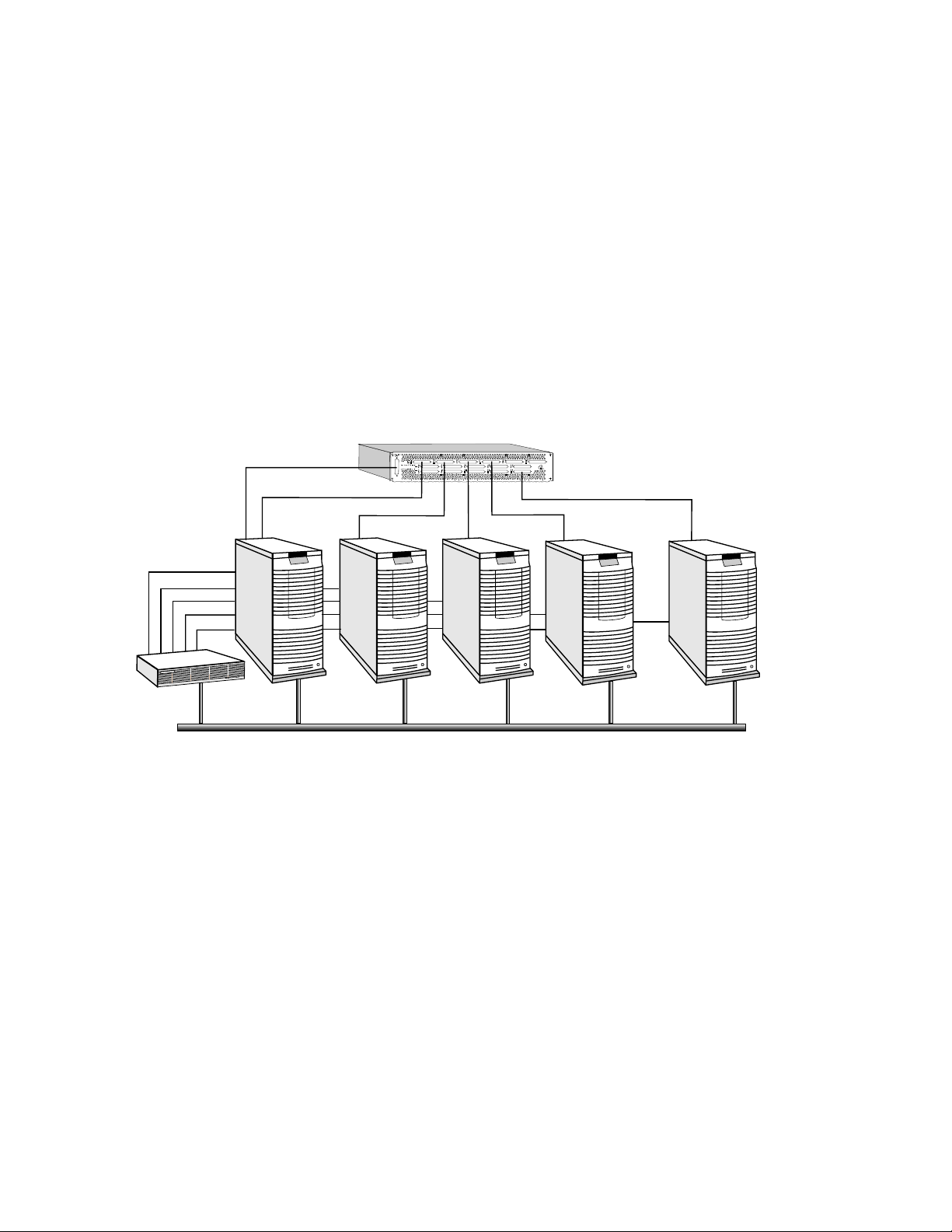
An RMS system comprises a network of computers (referred to as nodes) as shown in
Figure 2.1
each node runs a single copy of UNIX. Nodes used interactively to login to the RMS
. Each node may have single or multiple processors (such as a SMP server);
Overview of RMS 2-1
Page 20
The System Architecture
system are also connected to an external LAN. The application nodes, used for running
parallel programs, are accessed through the RMS.
Figure 2.1: A Network of Nodes
SwitchNetworkControl
QM-S16
Switch
SwitchNetwork
...
Terminal
Concentrator
ManagementNetwork
InteractiveNodes
withLAN/FDDI
Interface
ApplicationNodes
All of the nodes are connected to a management network (normally, a 100 BaseT
Ethernet). They may also be connected to a Compaq AlphaServer SC Interconnect, to
provide high-performance user-space communications between application processes.
The RMS processes that manage the system reside either on an interactive node or on a
separate management server. This node, known as rmshost, holds the RMS database,
which stores all state for the RMS system.
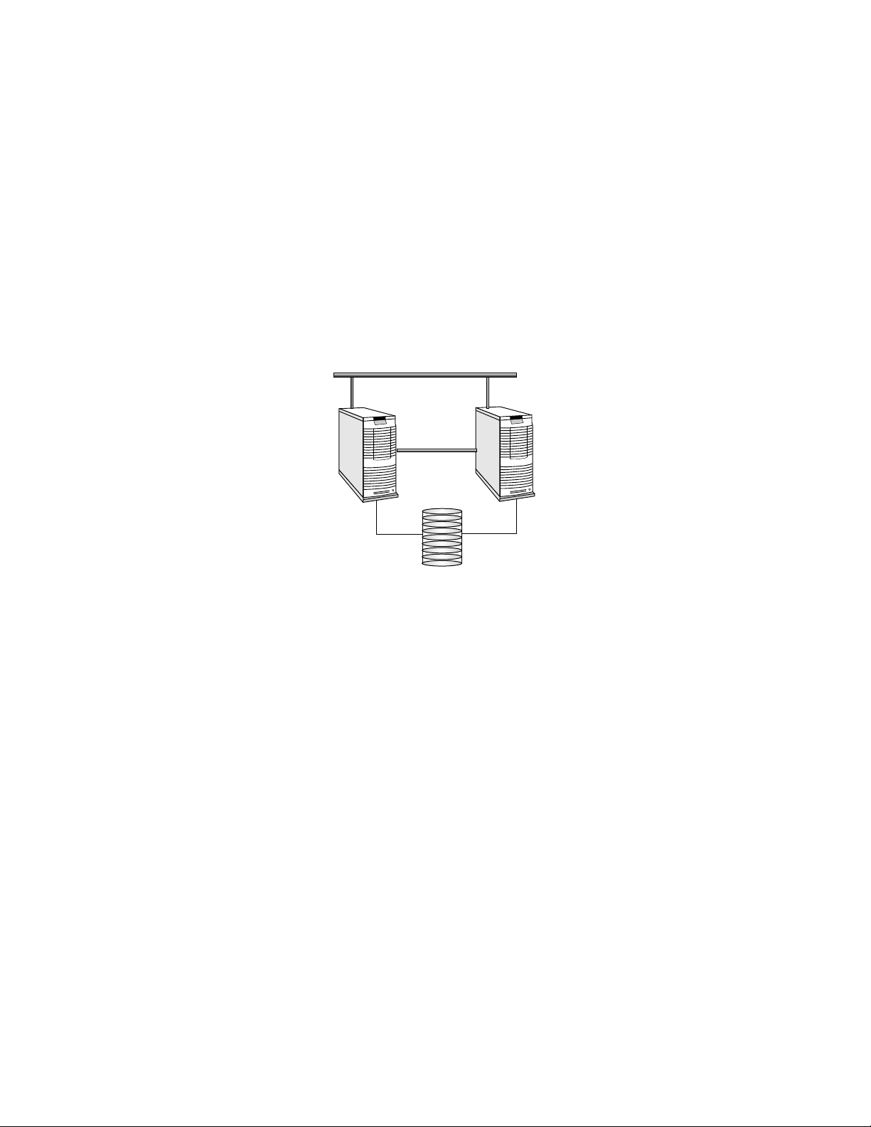
For high-availability installations, the rmshost node should be an interactive node
rather than a management server. This will allow you to configure the system for
failover, as shown in Figure 2.2 (see Chapter 15 of the System Administration Guide for
details).
2-2 Overview of RMS
Page 21
The Role of the RMS
Figure 2.2: High Availability RMS Configuration
RMSHost BackupRMSHost
RMSDatabase
The RMS processes run on the node with the name rmshost, which migrates to the
backup on fail-over. The database is held on a shared disk, accessible to both the
primary and backup node.
2.3 The Role of the RMS
The RMS provides a single point interface to the system for resource management. This
interface enables a system administrator to manage the system resources (CPUs,
memory, disks, and so on) effectively and easily. The RMS includes facilities for the
following administrative functions:
Monitoring controlling and monitoring the nodes in the network to ensure the
correct operation of the hardware
Fault diagnosis diagnosing faults and isolating errors; instigating fault recovery
and escalation procedures
Data collection recording statistics on system performance
Allocating CPUs allocating system resources to applications
Access control controlling user access to resources
Accounting single point for collecting accounting data
Parallel jobs providing the system support required to run parallel programs
Overview of RMS 2-3
Page 22

The Role of the RMS
Scheduling deciding when and where to run parallel jobs
Audit maintaining an audit trail of system state changes
From the user’s point of view, RMS provides tools for:
Information querying the resources of the system
Execution loading and running parallel programs on a given set of resources
Monitoring monitoring the execution of parallel programs
2.3.1 The Structure of the RMS
RMS is implemented as a set of UNIX commands and daemons, programmed in C and
C++, using sockets for communications. All of the details of the system (its
configuration, its current state, usage statistics) are maintained in a SQL database, as
shown in
Chapter 10 (The RMS Database) for details of the database.
Figure 2.3. See Section 2.3.4 for an overview and
2.3.2 The RMS Daemons
A set of daemons provide the services required for managing the resources of the system.
To do this, the daemons both query and update the database (see Section 2.3.4).
• The Database Manager, msqld, provides SQL database services.
• The Machine Manager, mmanager, monitors the status of nodes in an RMS system.
• The Partition Manager, pmanager, controls the allocation of resources to users and
the scheduling of parallel programs.
• The Switch Network Manager, swmgr, supervises the operation of the Compaq
AlphaServer SC Interconnect, monitoring it for errors and collecting performance
data.
• The Event Manager, eventmgr, runs handlers in response to system incidents and
notifies clients who have registered an interest in them.
• The Transaction Log Manager, tlogmgr, instigates database transactions that have
been requested in the Transaction Log. All client transactions are made through this
mechanism. This ensures that changes to the database are serialized and an audit
trail is kept.
• The Process Manager, rmsmhd, runs on each node in the system. It starts the other
RMS daemons.
2-4 Overview of RMS
Page 23

• The RMS Daemon, rmsd, runs on each node in the system. It loads and runs user
processes and monitors resource usage and system performance.
The RMS daemons are described in more detail in Chapter 4 (RMS Daemons).
2.3.3 The RMS Commands
RMS commands call on the RMS daemons to get information about the system, to
distribute work across the system, to monitor the state of programs and, in the case of
administrators, to configure the system and back it up. A suite of these RMS client
applications is supplied. There are commands for users and commands for system
administrators.
The user commands for gaining access to the system and running parallel programs are
as follows:
• allocate reserves resources for a user.
• prun loads and runs parallel programs.
• rinfo gets information about the resources in the system.
• rmsexec performs load balancing for the efficient execution of sequential programs.
The Role of the RMS
• rmsquery queries the database. Administrators can also use rmsquery to update
the database.
The system administration commands for managing the system are as follows:
• nodestatus gets and sets node status information.
• rcontrol starts, stops and reconfigures services.
• rmsbuild populates the RMS database with information on a given system.
• rmsctl starts and stops RMS and shows the system status.
• rmshost reports the name of the node hosting the RMS database.
• rmstbladm builds and maintains the database.
• msqladmin performs database server administration.
The services available to the different types of user (application programmer, operator,
system administrator) are subject to access control. Access control restrictions are
embedded in the SQL database, based on standard UNIX group IDs (see
Overview of RMS 2-5
Page 24

RMS Management Functions
Section 10.2.20). Users have read access to all tables but no write access. Operator and
administrative applications are granted limited write access. Password-protected
administrative applications and RMS itself have full read/write access.
The RMS commands are described in more detail in Chapter 5 (RMS Commands).
2.3.4 The RMS Database
The database provides a platform-independent interface to the RMS system. Users and
administrators can interact with the database using standard SQL queries. For example,
the following query displays details about the nodes in the machine. It selects fields
from the table called nodes (see Section 10.2.14). The query is submitted through the
RMS client rmsquery.
$ rmsquery "select name,status from nodes"
atlasms running
atlas0 running
atlas1 running
atlas2 running
atlas3 running
Figure 2.3: The Database
RMS uses the mSQL database engine from Hughes Technologies (for details see
http://www.Hughes.com.au). Client applications may use C, C++, Java, HTML or
UNIX script interfaces to generate SQL queries. See the Quadrics support page
http://www.quadrics.com/web/support for details of the SQL language.
2-6 Overview of RMS
NodeConfiguration
NetworkConfiguration
AccessControl
ResourceQuotas
Accounting
Auditing
UsageStatistics
SystemState
InternalSupport
Page 25

2.4 RMS Management Functions
The RMS gives the system administrator control over how the resources of a system are
assigned to the tasks it must perform. This includes the allocation of resources
(Section 2.4.1), scheduling policies (Section 2.4.2), access controls and accounting
(Section 2.4.3) and system configuration (Section 2.4.4).
2.4.1 Allocating Resources
The nodes in an RMS system can be configured into mutually exclusive sets known as
partitions as shown in Figure 2.4. The administrator can create partitions with different
mixes of resources to support a range of uses. For example, a system may have to cater
for a variety of processing loads, including the following:
• Interactive login sessions for conventional UNIX processes
• Parallel program development
• Production execution of parallel programs
• Distributed system services, such as database or file system servers, used by
conventional UNIX processes
RMS Management Functions
• Sequential batch streams
Figure 2.4: Partitioning a System
Login
Parallel
Sequential
batch
The system administrator can allocate a partition with appropriate resources for each of
these tasks. Furthermore, the administrator can control who accesses the partitions (by
user or by project) and how much of the resource they can consume. This ensures that
resources intended for a particular purpose, for example, running production parallel
codes, are not diverted to other uses, for example, running user shells.
Overview of RMS 2-7
Page 26

RMS Management Functions
A further partition, the root partition, is always present. It includes all nodes. It does
not have a scheduler. The root partition can only be used by administrative users (root
and rms by default).
2.4.2 Scheduling
Partitions enable different scheduling policies to be put into action. On each partition,
one or more of three scheduling policies can be deployed to suit the intended usage:
1. Gang scheduling of parallel programs, where all processes in a program are
scheduled and de-scheduled together. This is the default scheduling policy for parallel
partitions.
2. Regular UNIX scheduling with the addition of load balancing, whereby the user can
run a sequential program on a lightly loaded node. The load may be judged in terms
of free CPU time, free memory or number of users.
3. Batch scheduling, where the use of resources is controlled by a batch system.
Scheduling parameters such as time limits, time slice interval and minimum request
size are applied on an individual partition basis. Default priorities, memory limits and
CPU usage limits can be applied to users or projects to tune the partition’s workload. For
details see Chapter 6 (Access Control, Usage Limits and Accounting) and
Chapter 7 (RMS Scheduling).
The partition shown in Figure 2.5 has its CPUs allocated to five parallel jobs. The jobs
have been allocated CPUs in two different ways: jobs 1 and 2 use all of the CPUs on each
node; jobs 3, 4 and 5 are running with only one or two CPUs per node. RMS allows the
user to specify how their job will be laid out, trading off the competing benefits of
increased locality on the one hand against increased total memory size on the other.
With this allocation of resources, all five parallel programs can run concurrently on the
partition.
Figure 2.5: Distribution of Processes
4CPUs
2-8 Overview of RMS
0
4
8
12
0
4
1
5
9
13
1
5
2
6
10
14
2
6
0011223
3
4
5
6
7
Job3
4
5
6
7
Job4
0
2
4
6
Job5
3
7
11
15
3
Job1
Job2
7
16Nodes
1
3
5
7
Page 27

RMS Management Functions
The RMS scheduler allocates contiguous ranges of nodes with a given number of CPUs
per node1. Where possible each resource request is met by allocating a single range of
nodes. If this is not possible, an unconstrained request (those that only specify the
number of CPUs required) may be satisfied by allocating CPUs on disjoint nodes. This
ensures that an unconstrained resource request can utilize all of the available CPUs.
The scheduler attempts to find free CPUs for each request. If this is not possible, the
request blocks until CPUs are available. RMS preempts programs when a higher priority
job is submitted, as shown in Figure 2.6. Initially, CPUs have been allocated for resource
requests 1 and 2. When the higher priority resource request 3 is submitted, 1 and 2 are
suspended; 3 runs to completion after which 1 and 2 are restarted.
Figure 2.6: Preemption of Low Priority Jobs
startjobs
Resource1
0 1 2
Resource2
0 2 4 6
3 4 5
suspendjobs
startjob
jobends
resumejobs
Resource1
0 1 2
3 4 5
2.4.3 Access Control and Accounting
Users are allocated resources on a per-partition basis. Resources in this context include
both CPUs and memory. The system administrator can control access to resources both
at the individual user level and at the project level (where a project is a list of users).
This means that default access controls can be set up at the project level and overridden
on an individual user basis as required. The access controls mechanism is described in
1
The scheduler allocates contiguous ranges of nodes so that processes may take advantage of the Compaq
AlphaServer SC Interconnect hardware support for broadcast and barrier operations which operate over a
contiguous range of network addresses.
1 3 5 7
Resource3
2 310 4 5 6 7
10
98
12
11
0 2 4 6
1 3 5 7
13 14
Resource2
15
Overview of RMS 2-9
Page 28

RMS Management Functions
detail in Chapter 6 (Access Control, Usage Limits and Accounting).
Each partition, except the root partition, is managed by a Partition Manager (see
Section 4.4), which mediates user requests, checking access permissions and usage
limits before scheduling CPUs and starting user jobs.
An accounting record is created as CPUs are allocated to each request. It is updated
periodically until the resources are freed. The accounting record itemizes CPU and
memory usage, indexed by job, by user and by project.
2.4.4 RMS Configuration
The set of partitions active at any time is known as a configuration. A system will
normally have a number of configurations, each appropriate to a particular operating
pattern. For example, there may be one configuration for normal working hours and
another for night time and weekend operation.
The CPUs allocated to a partition may vary between configurations. For example, a login
partition (nodes allocated for interactive use) may have more nodes allocated during
working hours than at night – it may even be absent from the night time configuration.
A pair of configurations are shown in Figure 2.7.
Figure 2.7: Two Configurations
16nodes,4CPUspernode
Day
Login Development
Night
Parallel
RMS supports automated reconfiguration at shift changes as well as dynamic
Parallel
reconfiguration in response to a request from an operator or administrator. The RMS
client rcontrol (Page 5-20) manages the switch-over from one configuration to another.
For automatic reconfiguration, rcontrol can be invoked from a cron job.
2-10 Overview of RMS
Page 29

3.1 Introduction
RMS provides users with tools for running parallel programs and monitoring their
execution, as described in Chapter 5 (RMS Commands). Users can determine what
resources are available to them and request allocation of the CPUs and memory required
to run their programs. This chapter describes the structure of parallel programs under
RMS and how they are run.
A parallel program consists of a controlling process, prun, and a number of application
processes distributed over one or more nodes. Each process may have multiple threads
running on one or more CPUs. prun can run on any node in the system but it normally
runs in a login partition or on an interactive node.
3
Parallel Programs Under RMS
In a system with SMP nodes, RMS can allocate CPUs so as to use all of the CPUs on the
minimum number of nodes (a block distribution); alternatively, it can allocate a specified
number of CPUs on each node (a cyclic distribution). This flexibility allows users to
choose between the competing benefits of increased CPU count and memory size on each
node (generally good for multithreaded applications) and increased numbers of nodes
(generally best for applications requiring increased total memory size, memory
bandwidth and I/O bandwidth).
Parallel programs can be written so that they will run with varying numbers of CPUs
and varying numbers of CPUs per node. They can, for example, query the number of
processors allocated and determine their data distributions and communications
patterns accordingly (see Appendix C (RMS Kernel Module) for details).
Parallel Programs Under RMS 3-1
Page 30

Resource Requests
3.2 Resource Requests
Having logged into the system, a user makes a request for the resources needed to run a
parallel program by using the RMS commands prun (see Page 5-11) or allocate (see
Page 5-3). When using the prun command, the request can specify details such as the
following:
• The partition on which to run the program (the -p option)
• The number of processes to run (the -n option)
• The number of nodes required (the -N option)
• The number of CPUs required per process (the -c option)
• The memory required per process (the RMS_MEMLIMITenvironment variable)
• The distribution of processes over the nodes (the -m, -B and -R options)
• How standard input, output and error streams should be handled (the -i, -o and -e
options)
• The project to which the program belongs for accounting and scheduling purposes
(the -P option)
Two variants of a program with eight processes are shown in Figure 3.1: first, with one
process per node; and then, with two processes per node.
Figure 3.1: Distribution of Parallel Processes
0 1 2 3 4 5 6 7
0 1
4 5
3-2 Parallel Programs Under RMS
1ProcessPerNode
2 3
6 7
2ProcessesPerNode
Page 31

The resource request is sent to the Partition Manager, pmanager (described in
Section 4.4). The Partition Manager performs access checks (described in
Chapter 6 (Access Control, Usage Limits and Accounting)) and then allocates CPUs
according to the policies established for the partition (see Chapter 7 (RMS Scheduling)).
RMS makes a distinction between allocating resources and starting jobs on them. Before
the Partition Manager schedules a parallel program, it will ensure that the required
CPUs and memory are allocated. Note that this may cause requests to block for longer
than you might expect – especially when the job has not specified how much memory it
requires. Once CPUs have been allocated, jobs can be started on them immediately.
3.3 Loading and Running Programs
A simple parallel program is shown in Figure 3.2. It has eight application processes,
distributed over four nodes, two processes per node.
Figure 3.2: Loading and Running a Parallel Program
Loading and Running Programs
PartitionManager
prun
RMSNode
stdio
rmsd
rmsloader
0
FourNodesinaParallelPartition
4
1
5
2
6
3
7
Once the CPUs have been allocated, prun asks the pmanager to start the application
processes on the allocated CPUs. The pmanager does this by instructing the daemons
running on each of the allocated nodes to start the loader process rmsloader on the
user’s behalf.
The rmsloader process starts the application processes executing, forwarding their
stdout and stderr streams to prun (unless otherwise directed). Meanwhile, prun
supplies information on the application processes as requested by rmsloader and
forwards stdout and stderr to the controlling terminal or output files.
prun forwards stdin and certain signals (QUIT, USR1, USR2, WINCH) to the application
processes. If prun is killed, RMS cleans up the parallel program, killing the application
Parallel Programs Under RMS 3-3
Page 32

Loading and Running Programs
processes, removing any core files if requested (see Page 5-11) and then deallocating the
CPUs.
The application processes are run from the user’s current working directory with the
current limits and group rights. The data and stack size limits may be reduced if RMS
has applied a memory limit to the program.
During execution, the processes may be suspended at any time by the scheduler to allow
a program with higher priority to run. All of the processes in a parallel program are
suspended together under the gang-scheduling policy used by RMS for parallel programs
(see Chapter 7 (RMS Scheduling) for details). They are restarted together when the
higher priority program has completed.
A parallel program exits when all of its processes have exited. When this happens, the
rmsloader processes reduce the exit status back to the controlling process by
performing a global OR of the exit status of each of the processes. If prun is run with
verbose reporting enabled, a non-zero exit status is accompanied by a message, as shown
in the following example:
$ prun -v myprog
...
myprog: process 0 exited with status 1
If the level of reporting is increased with the -vv option, prun provides a commentary
on the resource request. With the -vvv option, rmsloader also outputs information
identifying the activity on each node running the program, as shown in the following
example.
$ prun -vvv myprog
prun: running /home/duncan/myprog
prun: requesting 2 CPUs
prun: starting 2 processes on 2 cpus default memlimit no timelimit
prun: stdio server running
prun: loader 1 starting on atlas1 (10.128.0.7)
prun: loader 0 starting on atlas0 (10.128.0.8)
loader[atlas1]: program description complete
loader[atlas1]: nodes 2 contexts 1 capability type 0xffff8002 entries 2
loader[atlas1]: run process 1 node=5 cntx=244
prun: process 1 is pid 1265674 on atlas1
loader[atlas0]: program description complete
loader[atlas0]: nodes 2 contexts 1 capability type 0xffff8002 entries 2
loader[atlas0]: run process 0 node=4 cntx=244
prun: process 0 is pid 525636 on atlas0
...
When the program has exited, the CPUs are deallocated and the scheduler is called to
service the queue of waiting jobs.
3-4 Parallel Programs Under RMS
Page 33

Loading and Running Programs
Sometimes, it is desirable for a user to be granted more control over the use of a
resource. For instance, the user may want to run several jobs concurrently or use the
same nodes for a sequence of jobs. This functionality is supported by the command
allocate (see Page 5-3) which allows a user to allocate CPUs in a parallel partition to a
UNIX shell. These CPUs are used for subsequent parallel jobs started from this shell.
The CPUs remain allocated until the shell exits or a time limit expires (see Section 7.3
and Section 7.4.5).
Parallel Programs Under RMS 3-5
Page 34

Page 35

4.1 Introduction
This chapter describes the role of the RMS daemons. There are daemons that run on the
rmshost node providing services for the system as a whole:
msqld Manages the database (see Section 4.2).
mmanager Monitors the health of the machine as a whole (see Section 4.3).
pmanager Controls the use of resources (see Section 4.4).
swmgr Monitors the health of the Compaq AlphaServer SC Interconnect (see
4
RMS Daemons
Section 4.5).
tlogmgr Carries out transactions on behalf of RMS servers (see Section 4.6).
eventmgr Provides a system-wide event-handling service (see Section 4.7).
There are daemons that run on each node, providing support for RMS functionality on
that node:
rmsmhd Acts as the Process Manager, starting all of the other RMS daemons
(see Section 4.8).
rmsd Carries out instructions from pmanager to run users’ programs (see
Section 4.9).
RMS Daemons 4-1
Page 36

The Machine Manager
4.1.1 Startup
RMS is started as each node executes the initialization script /sbin/init.d/rms with
the start argument on startup. This starts the rmsmhd daemon which, in turn, starts
the other daemons on that node.
The daemons can also be started, stopped and reloaded individually by rcontrol once
RMS is running. See Page 5-20 for details.
4.1.2 Log Files
Output from the management daemons is logged to the directory /var/rms/adm/log.
The log files are called daemon.log, where daemon gives the name of the RMS daemon,
such as swmgr. The Partition Managers are distinguished by suffixing pmanager with a
hyphen and then the name of the partition. For example, the Partition Manager for the
partition par1 is known is pmanager-par1.
Errors are logged to /var/rms/adm/log/error.log.
Output from rmsmhd and rmsd is logged to /tmp/rms.log on each node.
4.1.3 Daemon Status
The servers table contains information on the status of each daemon: the time it was
started, its process ID and the name of its host node (see Section 10.2.19 for details of
the table structure).
Note that the status field in the servers table is set to error if an error occurs when
starting an RMS daemon. The corresponding entry in the events table describes what
went wrong (see Chapter 8 (Event Handling) for details).
The command rinfo can be used to get reports on the status of each daemon. See
Page 5-32 for details.
4.2 The Database Manager
The Database Manager, msqld, manages the RMS database, providing an SQL interface
for its clients. Client applications may use C, C++, Java or UNIX scripts to generate SQL
queries for msqld.
The database holds all state information for RMS. This information is initially created
by the RMS client application rmsbuild (see Page 5-35). The information is updated by
the other RMS daemons as RMS operates. The information can be backed up, restored
and generally maintained using the database administration program, rmstbladm (see
Page 5-44).
4-2 RMS Daemons
Page 37

4.3 The Machine Manager
The Machine Manager, mmanager, is responsible for detecting and reporting changes in
the state of each node in the system. It records the current state of each node and any
changes in state in the database.
When a node is functioning correctly, rmsd, a daemon which runs on each node,
periodically updates the database. However, if the node crashes, or IP traffic to and from
the node stops, then these updates stop. RMS uses the external monitor, mmanager, to
check periodically the service level of each node. It monitors whether IP is functioning
and whether the RMS daemons on each node are operating.
4.3.1 Interaction with the Database
The Machine Manager records the current status of nodes in the nodes table (see
Section 10.2.14) while changes to node status are entered in the events table (see
Section 10.2.6).
The interval at which the Machine Manager performs status checks is set in the
attributes table (see Section 10.2.3) with the node-status-poll-interval
attribute. If this attribute is not present, the general attribute rms-poll-interval is
used instead.
The Partition Manager
4.4 The Partition Manager
The nodes in the RMS machine are configured into mutually exclusive sets known as
partitions (see Section 2.4). By restricting access to partitions, the system administrator
can reserve particular partitions for specific types of tasks or users. In this way, the
system administrator can ensure that resources are used most effectively; for example,
that resources intended for running parallel programs are not consumed running user
shells. The access restrictions are set up in the access_controls table (see
Section 10.2.1) of the RMS database.
Each partition is controlled by a Partition Manager, pmanager. The Partition Manager
mediates each user’s requests for resources (CPUs and memory) to run jobs in the
partition. It checks the user’s access permissions and resource limits before adding the
request to its scheduling queue. The request blocks until the resources are allocated for
the job.
When the resources requested by the user become available, the Partition Manager
instructs rmsd, a daemon that runs on each node in the partition (see Section 4.9), to
create a communications context for the user’s job. Finally, the Partition Manager
replies to the user’s request and the user’s job starts.
RMS Daemons 4-3
Page 38

The Partition Manager
The Partition Manager makes new scheduling decisions periodically and in response to
incoming resource requests (see Chapter 7 (RMS Scheduling) for details). These
decisions may result in jobs being suspended or resumed. Such scheduling operations,
together with those performed as jobs are killed, are performed by the Partition
Manager sending scheduling or signal delivery requests to the rmsds.
The Partition Manager is connected to its rmsds by a tree of sockets. Commands are
routed down this tree; they complete when an acknowledgement is returned. For
example, jobs are only marked as finished when the Partition Manager has confirmed
that all of their processes have exited.
If the tree of sockets is broken by a node crash, the Partition Manager marks the node’s
partition as blocked and generates an event. The node can then be rebooted or
configured out of the machine. If the node is rebooted, the rmsds reconnect and the
Partition Manager continues as before. If the node cannot be rebooted then the partition
must be halted, the node configured out and the partition restarted. Jobs that spanned
the failing node are cleaned up at this point. The other jobs run on unless explicitly
killed. Scheduling and signal delivery operations are suspended while the partition is
blocked.
4.4.1 Partition Startup
The Partition Manager is started by the rmsmhd daemon, running on the rmshost node,
on instruction from rcontrol (see Page 5-20). Once the partition is running, a startup
script /opt/rms/etc/pstartup is executed. This script performs site-specific and
OS-specific actions depending upon the partition type.
4.4.2 Interaction with the Database
The Partition Manager makes updates to the partitions table (see Section 10.2.16)
when it starts and as CPUs are allocated and freed.
The Partition Manager creates an entry in the resources table (see Section 10.2.18)
each time a user makes a request for resources to run a job. This entry is updated each
time CPUs are allocated or deallocated. The Partition Manager adds an entry to the
jobs table (see Section 10.2.10) as each job starts, updating it if the job is suspended or
resumed and when the job completes.
The Partition Manager creates an entry in the accounting statistics (acctstats) table
(see Section 10.2.2) when CPUs are allocated. The entry is updated periodically until the
request completes.
The Partition Manager consults the users table (see Section 10.2.24), the projects
table (see Section 10.2.17) and the access_controls table (see Section 10.2.1) to verify
users’ access permissions and usage limits.
4-4 RMS Daemons
Page 39

Configuration information about each partition is held in the partitions table (see
Section 10.2.16). The information is indexed by the name of the partition together with
the name of the active configuration.
4.5 The Switch Network Manager
The Switch Network Manager, swmgr, controls and monitors the Compaq AlphaServer
SC Interconnect (see Appendix A (Compaq AlphaServer SC Interconnect Terms)). It does
this using the switch network control interface connected to the parallel port of the
primary management node. If swmgr detects an error in the switch network, it updates
the status of the switch concerned and generates an event.
swmgr collects fan, power supply and temperature data from the Compaq AlphaServer
SC Interconnect modules, updating status information and generating events if
components fail or temperatures exceed their operating limits. See Section 9.5.4 for
site-specific details of configuring the swmgr.
4.5.1 Interaction with the Database
The Switch Network Manager creates and maintains the entries in the elites table
(see Section 10.2.5) and the switch_boards table (see Section 10.2.22). It maintains
entries in the elans table (see Section 10.2.4). In the event of errors, it creates entries
in the link_errors table (see Section 10.2.11).
The Transaction Log Manager
4.6 The Transaction Log Manager
The Transaction Log Manager, tlogmgr, executes change of state requests that have
been entered in the transactions table (see Section 10.2.23) by RMS administrative
clients. This mechanism is employed to serialize changes to the database and to provide
an audit trail of such changes.
The entry in the transactions table records who requested the change, and names the
service required together with any arguments to pass to the process on startup. A
transaction handle (a unique ID) is generated for the entry and passed to both the client
and the RMS daemon that provides the service.
The RMS daemon uses the transaction handle to label any results it produces, such as an
entry in the transaction_outputs table (see Section 10.1.3). The client uses the
handle to select the result from the relevant table. Output from the service is appended
to an output log. The name of this log is entered in the transactions table together
with the status of the transaction.
The services that are available are listed in the services table (see Section 10.2.20).
RMS Daemons 4-5
Page 40

The Process Manager
Each entry in the services table specifies which command to run, who can run it and
on which host.
4.6.1 Interaction with the Database
The Transaction Log Manager maintains the transactions table (see Section 10.2.23).
It consults the services table (see Section 10.2.20) in order to execute transactions on
behalf of its clients.
4.7 The Event Manager
When an RMS daemon detects an anomaly (such as a node crash or a high temperature
reading), it writes an event description to the events table (see Section 10.2.6). It is the
job of the Event Manager, eventmgr, to execute recovery scripts that either correct the
fault or report it to the operators if manual intervention is required.
On receiving an event notification, the Event Manager looks for a matching entry in the
event_handlers table (see Section 10.2.7), executing the handler script if it finds a
match (see Section 8.2 for details). If no match is found, it runs the default event
handler script; this script is site-specific, but it would typically run a command to
escalate the event through SNMP or email.
The Event Manager also implements the event-waiting mechanism that enables client
applications both to generate and to wait efficiently on a specified event. Typical events
include the following:
• Nodes changing state
• Partitions starting
• Transaction log entries being executed
The details that describe the event are held in the events table (see Section 10.2.6).
The Event Manager’s job is to notify interested clients that the event has occurred. This
frees the clients from having to poll for the information. For more information on RMS
event handling, see Chapter 8 (Event Handling).
4.7.1 Interaction with the Database
The Event Manager consults the events table (see Section 10.2.6) and the
event_handlers table (see Section 10.2.7).
4-6 RMS Daemons
Page 41

4.8 The Process Manager
The Process Manager, rmsmhd, is responsible for starting and stopping the other RMS
daemons. It runs on each node and is responsible for managing the other daemons that
run on its node. It starts them as the node boots, stops them as the node halts and starts
or stops them in response to requests from the RMS client application rcontrol (see
Page 5-20).
4.8.1 Interaction with the Database
RMS stores information regarding which daemons run on which nodes; this information
is stored centrally in the RMS database, rather than in node-specific configuration files.
On startup, the Process Manager checks the servers table (see Section 10.2.19) for
entries matching its node. This information is used to start the other daemons. If its
child processes (the other daemons) are killed, it checks the table to see whether they
should be restarted. The Process Manager creates its own entry in the servers table.
4.9 The RMS Daemon
The RMS daemon rmsd runs on each node in the machine. Its purpose is as follows:
The RMS Daemon
• To start application processes
• To implement scheduling decisions made by the Partition Manager
• To clean up after parallel programs when they have finished
• To execute RMS remote procedure calls on behalf of clients elsewhere in the network
• To collect accounting data and performance statistics
rmsd carries out the following tasks on behalf of the Partition Manager to run a user’s
parallel program:
• Creating and destroying communication contexts (see Section C.2)
• Starting the application loader, rmsloader.
• Delivering signals
• Suspending and resuming processes
• Collecting accounting data from the kernel
RMS Daemons 4-7
Page 42

The RMS Daemon
The rmsds communicate with each other and with the Partition Manager that controls
their node over a balanced tree of sockets. Requests (for example, to deliver a signal to
all processes in a parallel program) are passed down this tree to the appropriate range of
nodes. The results of each request are combined as they pass back up the tree.
rmsd is started by the RMS daemon rmsmhd and restarted when it exits – this happens
when a partition is shut down.
4.9.1 Interaction with the Database
rmsd records configuration information about each node (number of CPUs, amount of
memory and so on) in the nodes table (see
records usage statistics in the node statistics (node_stats) table (see Section 10.2.15).
The interval at which these statistics are sampled is set in the attributes table with
the cpu-stats-poll-interval attribute.
rmsd records details of the node’s Compaq AlphaServer SC Interconnect configuration in
the elans table as it starts (see Section 10.2.4 and
Appendix A (Compaq AlphaServer SC Interconnect Terms)).
Section 10.2.14) as it starts. It periodically
4-8 RMS Daemons
Page 43

5.1 Introduction
This chapter describes the RMS commands. RMS includes utilities that enable system
administrators to configure and manage the system, in addition to those that enable
users to run their programs.
RMS includes the following commands intended for use by system administrators:
rcontrol The rcontrol command is used to control the system resources.
rmsbuild The rmsbuild command creates and populates an RMS database for
5
RMS Commands
a given machine.
rmsctl The rmsctl script is used to stop and start the RMS system and to
report its status.
rmsquery The rmsquery command is used to select data from the database and,
in the case of system administrators, to update it.
rmstbladm The table administration rmstbladm program is used to create a
database, to back it up and to restore it.
The following utilities are used internally by RMS and may also be used by system
administrators:
nodestatus The nodestatus command is used to get or set the status or run
level of a node.
RMS Commands 5-1
Page 44

Introduction
rmshost The rmshost command reports the name of the node running the
msqladmin The msqladmin command is used for creating and deleting databases
RMS includes the following commands for all users of the system:
allocate The allocate command is used to reserve access to a set of CPUs
prun The prun command is used to run a parallel program or to run
rinfo The rinfo command is used to determine what resources are
rmsexec The rmsexec command is used to run a sequential program on a
The following sections describe the commands in more detail, listing them in
alphabetical order.
RMS management daemons.
and stopping the mSQL server.
either for running multiple tasks in parallel or for running a sequence
of commands on the same CPUs.
multiple copies of a sequential program.
available and which jobs are running.
lightly loaded node.
5-2 RMS Commands
Page 45

NAME
allocate – Reserves access to CPUs
SYNOPSIS
allocate [-hIv] [-B base] [-C CPUs] [-N nodes | all] [-n CPUs]
OPTIONS
-B base Specifies the number of the base node (the first node to use) in the
-C CPUs Specifies the number of CPUs required per node (default 1).
allocate(1)
[-p partition] [-P project] [-R request]
[script [args ...]]
partition. Numbering within the partition starts at 0. By default, the
base node is unassigned, leaving the scheduler free to select nodes
that are not in use.
-h Display the list of options.
-I Allocate CPUs immediately or fail. By default, allocate blocks until
resources become available.
-N nodes | all
Specifies the number of nodes to allocate (default 1). To allocate one
CPU on each node in the partition, use the argument all as follows:
allocate -N all. Either the -C option or the -n option can be
combined with -N but not both.
-n CPUs Specifies the total number of CPUs required.
-P project Specifies the name of the project with which the job should be
associated for scheduling and accounting purposes.
-p partition Specifies the target partition from which the resources are to be
allocated.
-R request Requests a particular configuration of resources. The types of
request currently supported are as follows:
RMS Commands 5-3
Page 46

allocate(1)
-v Specifies verbose operation.
DESCRIPTION
The allocate program allocates resources for subsequent use by the prun(1)
command. allocate is intended for use where a user wants to run a sequence of
commands or several programs concurrently on the same set of CPUs.
immediate=0 | 1
With a value of 1, this specifies that the request
should fail if it cannot be met immediately (this is
the same as the -I option).
hwbcast=0 | 1 With a value of 1, this specifies a contiguous range
of nodes and constrains the scheduler to queue the
request until a contiguous range becomes available.
rails=n In a multirail system, this specifies the number of
rails required, where 1 ≤ n ≤ 32.
Multiple requests can be entered as a comma-separated list, for
example, -R hwbcast=1,immediate=1.
The -p, -N, -C, -B and -n options control which CPUs are allocated. The -N option
specifies how many nodes are to be allocated. When this option is specified the user is
allocated a constant number of CPUs per node (default 1). The -C option specifies the
number of CPUs required per node. The alternative -n option specifies the total number
of CPUs to allocate. This option does not force the allocation of a constant number of
CPUs per node.
The -B option specifies the base of a contiguous range of nodes relative to the start of the
partition. The -N option specifies its extent. So for example -B0-N4 specifies the first
four nodes in the partition. Note that nodes that have been configured out are excluded.
The -B option should be used to gain access to a specific file system or device that is not
available on all nodes. If the -B option is used, the scheduler allocates a contiguous
range of nodes and the same number of CPUs on each node. Using this option causes a
request to block until the base node and any additional nodes required to run the
program are free.
The -p option specifies the partition from which CPUs can be allocated. CPUs cannot be
allocated from the root partition.
The Partition Manager, pmanager, allocates processing resources to users as and when
the resources are requested and become available. (See Section 4.4). By default, a
contiguous range of nodes is allocated to the request where possible. This enables
programs to take advantage of the system’s hardware broadcast facilities. The -R option
5-4 RMS Commands
Page 47

allocate(1)
can be used with hwbcast set to 1 to ensure that the range of nodes allocated is
contiguous.
Before allocating resources, the Partition Manager checks the resource limits imposed
on the current project. The project can be specified explicitly with the -P option. This
overrides the value of the environment variable RMS_PROJECT or any default setting in
the users table. (See Section 10.2.24).
The script argument (with optional arguments) can be used in two different ways, as
follows:
1. script is not specified, in which case an interactive command shell is spawned with
the resources allocated to it. The user can confirm that resources have been allocated
to an interactive shell by using the rinfo command. (See Page 5-32).
The resources are reserved until the shell exits or until a time limit defined by the
system administrator expires, whichever happens first. (See Section 10.2.16).
Parallel programs, executed from this interactive shell, all run on the shell’s
resources (concurrently, if sufficient resources are available).
2. script specifies a shell script, in which case the resources are allocated to the named
subshell and freed when execution of the script completes.
ENVIRONMENT VARIABLES
The following environment variables may be used to identify resource requirements and
modes of operation to allocate. They are used where no equivalent command line
options are given.
RMS_IMMEDIATE Controls whether to exit (value 1) rather than block (value 0) if
resources are not immediately available. The -I option overrides the
value of this environment variable. By default, allocate blocks until
resources become available. Root resource requests are always met.
RMS_MEMLIMIT Specifies the maximum amount of memory required. This must be
less than or equal to the limit set by the system administrator.
RMS_PARTITION Specifies the name of a partition. The -p option overrides the value of
this environment variable.
RMS_PROJECT Specifies the name of the project with which the request should be
associated for accounting purposes. The -P option overrides the value
of this environment variable.
RMS Commands 5-5
Page 48

allocate(1)
RMS_TIMELIMIT Specifies the execution time limit in seconds. The program will be
RMS_DEBUG Specifies whether to execute in verbose mode and display diagnostic
allocate passes all existing environment variables through to the shell that it
executes. In addition, it sets the following environment variable:
RMS_RESOURCEID The identifier of the allocated resource.
EXAMPLES
To run a sequence of jobs on the same CPUs:
$ allocate -N 16 jobscript
signaled either after this time has elapsed or after any time limit
imposed by the system has elapsed. The shorter of the two time limits
is used.
messages. Setting a value of 1 or more will generate additional
information that may be useful in diagnosing problems. (See
Section 9.6). If this environment variable is not set the -v option
enables reporting of resource request debug information.
where jobscript is a shell script such as the following:
#!/bin/sh
# simple job script
prun -n 16 program1
prun -n 16 program2
If the script was run directly then each resource request would block until resources
became available and there would be no guarantee of both requests using the same
CPUs. By running the script under allocate, there is only one resource request and
both jobs are run on the same CPUs.
To run two programs on the same CPUs at the same time:
$ allocate -N 16 -C 2 << EOF
prun program1 &
prun program2 &
rinfo
wait
EOF
WARNINGS
In earlier versions, the -i option specified immediate mode. This functionality has been
moved to the -I option. Use of -i is now deprecated. If -i is specified without an
5-6 RMS Commands
Page 49

argument, it is interpreted as -I and the user is warned that this feature should not be
used anymore.
SEE ALSO
prun, rinfo
allocate(1)
RMS Commands 5-7
Page 50

nodestatus(1)
NAME
nodestatus – Gets or sets the status or run level of each node
SYNOPSIS
nodestatus [-bhr] [status]
OPTIONS
-b Operate in the background.
-h Display the list of options.
-r Get/set run level.
DESCRIPTION
The nodestatus command is used to update status information in the RMS database as
nodes are booted or halted. When run without arguments, nodestatus gets the status
of the node on which it is running from the Machine Manager. When run with the -r
flag, nodestatus gets the current run level.
When nodestatus is run with the status argument, it updates the node’s status or,
if the -r flag is set, it updates the node’s run level. The change is reflected in the
nodes table for the node on which the command is running. (See Section 10.2.14). This
mechanism is used to track the progress of booting a node. Administrative privileges are
required to update the status or run level of a node.
The status can be one of these values: not responding, active or running.
Status updates may be delayed if the node running the database server is down. If
background operation is specified with the -b option, nodestatus runs in the
background and keeps trying until the database server is up and running.
5-8 RMS Commands
Page 51

NAME
msqladmin – Perform administrative operations on the mSQL database server
SYNOPSIS
msqladmin(1)
msqladmin [-q] [-f
OPTIONS
-f confFile Specify a non-default configuration file to be loaded. The default
-h host Specify a remote hostname or IP address on which the mSQL server
-q Put msqladmin into quiet mode. If this flag is specified, msqladmin
DESCRIPTION
msqladmin is used to perform administrative operations on an mSQL database server.
Such tasks include the creation of databases, performing server shutdowns and so on.
The available commands for msqladmin are:
confFile] [-h host] command
action is to load the standard configuration file located in
/var/rms/msql.conf.
(msql2d) is running. The default is to connect to a server on the
localhost using a UNIX domain socket rather than TCP/IP (which
gives better performance).
will not prompt the user to verify dangerous actions (such as dropping
a database).
create db_name
Creates a new database called db_name.
drop db_name Removes the database called db_name from the server. This will also
delete all data contained in the database specified.
shutdown Terminates the mSQL server.
reload Forces the server to reload ACL information.
version Displays version and configuration information about the currently
running server.
RMS Commands 5-9
Page 52

msqladmin(1)
stats Displays server statistics.
Most administrative functions can only be executed by the user specified in the run-time
configuration as the admin user (rms). They can also only be executed from the host on
which the server process is running (for example you cannot shut down a remote server
process).
EXAMPLES
# msqladmin version
Version Details :-
Configuration Details :-
msqladmin version 2.0.11
mSQL server version 2.0.11
mSQL protocol version 23
mSQL connection Localhost via UNIX socket
Target platform OSF1-V5.0-alpha
Default config file /var/rms/msql.conf
TCP socket 1114
UNIX socket /var/rms/adm/msql/msql2.sock
mSQL user rms
Admin user rms
Install directory /var/rms
PID file location /var/rms/adm/msql/msql2.pid
Memory Sync Timer 120
Hostname Lookup True
5-10 RMS Commands
Page 53

NAME
prun – Runs a parallel program
SYNOPSIS
prun [-hIOrstv] [-B base] [-c cpus] [-e mode] [-i mode] [-o mode]
OPTIONS
-B base Specifies the number of the base node (the first node to use) in the
-c cpus Specifies the number of CPUs required per process (default 1).
prun(1)
[-N nodes | all] [-n procs] [-m block | cyclic] [-P project]
[-p partition] [-R request] program [args ...]
partition. Numbering within the partition starts at 0. By default, the
base node is unassigned, leaving the scheduler free to select nodes
that are not in use.
-h Display the list of options.
-I Allocate CPUs immediately or fail. By default, prun blocks until
resources become available.
-e mode Specifies how standard error output is redirected. Valid values for
mode and their meanings are described below.
-i mode Specifies how standard input is redirected. Valid values for mode and
their meanings are described below.
-o mode Specifies how standard output is redirected. Valid values for mode
and their meanings are described below.
-m block | cyclic
Specifies whether to use block (the default) or cyclic distribution of
processes over nodes.
-N nodes | all
Specifies the number of nodes required. To use all nodes in a partition
select the all argument as follows: prun -N all. If the number of
nodes is not specified then the RMS scheduler will allocate one CPU
per process.
RMS Commands 5-11
Page 54

prun(1)
-n procs Specifies the number of processes required. The -n and -N options
can be combined to control how processes are distributed over nodes.
If neither is specified, prun starts one process.
-O Allows resources to be over-committed. Set this flag to run more than
one process per CPU.
-P project Specifies the name of the project with which the job should be
associated for scheduling and accounting purposes.
-p partition Specifies the partition on which to run the program. By default, the
partition specified in the attributes table is used. The default is
parallel. (See Section 10.2.3).
-R request Requests a particular configuration of resources. The types of
request currently supported are as follows:
immediate=0 | 1
With a value of 1, this specifies that the request
should fail if it cannot be met immediately (the
same as the -I option).
hwbcast=0 | 1 With a value of 1, this specifies a contiguous range
of nodes and constrains the scheduler to queue the
request until a contiguous range of nodes becomes
available.
-r Run processes using rsh. Used for administrative operations such as
-s Print statistics as the job exits.
-t Prefix output with the process number.
-v Specifies verbose operation. Multiple vs increase the level of output:
5-12 RMS Commands
rails=n In a multirail system, this specifies the number of
rails required, where 1 ≤ n ≤ 32.
Multiple requests can be entered as a comma-separated list, for
example, -R hwbcast=1,immediate=1.
starting and stopping RMS.
-vv shows each stage in running a program and -vvv enables debug
output from the rmsloader processes on each node.
Page 55

DESCRIPTION
prun(1)
The prun program executes multiple copies of the specified
prun automatically requests resources for the program unless it is executed from a shell
that already has resources allocated to it. (See
The way in which processes are allocated to CPUs is controlled by the -c, -n, -p, -B and
-N options. The -n option specifies the total number of processes to run. The -c option
specifies the number of CPUs required per process, this defaults to 1. The -N option
specifies how many nodes are to be used.
If the -N option is not used then the scheduler selects CPUs for the program from any of
the available nodes. Where possible RMS will allocate a contiguous range of nodes, but
will only be constrained to do so if the -B or -R hwbcast=1 options are set. If the -N is
used, the scheduler allocates the specified number of nodes (allocating a contiguous
range of nodes if possible) and the same number of CPUs on each node. By default, a
contiguous range of nodes is allocated to the request where possible. This enables
programs to take advantage of the system’s hardware broadcast facilities. The -R option
can be used with hwbcast set to 1 to ensure that the range of nodes allocated is
contiguous.
The -B option specifies the base of a contiguous range of nodes relative to the start of the
partition. The -N option specifies its extent. So for example -B0 -N4 specifies the first
four nodes in the partition. Note that nodes that have been configured out are excluded.
The -B option should be used to gain access to a specific file system or device that is not
available on all nodes. If the -B option is used, the scheduler allocates a contiguous
range of nodes and the same number of CPUs on each node. Using this option causes a
request to block until the base node and any additional nodes required to run the
program are free.
Page 5-3).
program on a partition.
The -I option specifies that resource requests should fail if they cannot be met
immediately. The default is to block until CPUs are available.
The -m option specifies how processes are to be distributed over nodes. The choice is
between block (the default) and cyclic. If a program has n processes with identifiers
0,1,...n-1 distributed over N nodes then, in a block distribution, the first n/N
processes are allocated to the first node and so on. If the distribution is cyclic, process 0
runs on the first node, process 1 on the second and so on until process N-1 is placed on
the last node, at which stage the distribution wraps around, with process N running on
the first node and so on.
The -p option specifies the partition to use. If no partition is specified then the default
partition is used. The default partition is stored in the attributes table. (See
Section 10.2.3). Note that use of the root partition (all nodes in the machine) is
restricted to administrative users.
RMS Commands 5-13
Page 56

prun(1)
Before allocating resources, prun checks the resource limits imposed on the current
project. The project can be specified explicitly with the -P option. This overrides the
value of the environment variable RMS_PROJECT or any default setting in the users
table. (See Section 10.2.24).
By default, when running a parallel program, prun forwards standard input to the
process with an identifier of 0. The -i option requests a different mode of operation.
Valid values for mode and their meanings are as follows:
rank Forward standard input to the process that is identified by rank
where 0 ≤ rank ≤ n-1 and n is the number of processes in the
program.
all Broadcast standard input to all of the processes.
none Do not forward standard input.
file prun opens the named file and associates it with the standard input
stream so that each process reads standard input from the file. If the
file does not exist, a read returns EOF.
file.% prun expands the % character to generate and open a separate file
name for each process: process 0 reads standard input from file.0,
process 1 reads standard input from file.1 and so on. If the file does
not exist, a read returns EOF.
If the mode is rank or all, prun polls its standard input and forwards the data to the
rmsloader of the application process (or processes if the mode is all). rmsloader
writes the data to the standard input pipe for the process. This write may fail if the pipe
is full, the application has not read the data. If this happens, rmsloader will
periodically attempt to resend the data to the pipe. prun will not poll for further
standard input until it has received an acknowledgement from the process (or all
processes in the case of broadcast input) to say that this operation has completed.
The -o and -e options control the redirection and filtering of standard output and
standard error respectively. Valid values for mode and their meanings for these options
are as follows:
rank Redirect to prun standard output (or standard error) from the process
all Redirect standard output (or standard error) from all processes to
5-14 RMS Commands
identified by rank where 0 ≤ rank ≤ n-1 and n is the number of
processes in the program.
prun. This is the default.
Page 57

prun(1)
none Do not redirect standard output (or standard error) from any process.
file prun opens the named file for output and associates it with the
standard output (standard error) stream so that each process writes
standard output (standard error) to the file.
file.% prun expands the % character to generate and open for output a
separate file name for each process: process 0 writes standard output
(standard error) to file.0, process 1 writes to file.1 and so on.
Standard output from a parallel program is line-buffered and redirected to prun when a
newline character is received. Output that does not end in a newline is buffered by
rmsloader.
Standard error is unbuffered and forwarded to prun as soon as it is received by
rmsloader.
There is no global synchronization of output from a parallel program. If multiple
processes output data, the order in which the data is output will not necessarily be the
same each time the program is run.
prun exits when all of the processes in the parallel program have exited or when one
process has been killed. If all processes exit cleanly then the exit status of prun is the
global OR of their individual exit status values. If one of the processes is killed, prun will
exit with a status value of 128 plus the signal number. prun can also exit with the
following codes:
125 One or more processes were still running when the exit timeout expired.
126 prun was run with the -I option and resources were not available.
127 prun was run with invalid arguments.
If an application process started by prun is killed, RMS will run a post mortem core
analysis script that generates a backtrace if it can find a core file for the process.
The attribute rms-keep-core in the attributes table determines whether core files
are saved. (See Section 10.2.3). The environment variable RMS_KEEP_CORE can be set to
override the value in the attributes table.
Core files are saved in the directory local-corepath/resource-id. The value of
local-corepath is defined in the attributes table. The resource-id can be listed
by rinfo. (See Page 5-32). prun also sets the environment variable RMS_RESOURCE_ID
to the value of the resource identifier.
RMS Commands 5-15
Page 58

prun(1)
ENVIRONMENT VARIABLES
The following environment variables may be used to identify resource requirements and
modes of operation to prun. These environment variables are used where no equivalent
command line options are given:
RMS_IMMEDIATE Controls whether to exit rather than block if resources are not
immediately available. The -I option overrides the value of this
environment variable. By default, prun blocks until resources become
available. Root resource requests are always met.
RMS_KEEP_CORE Controls whether core files are saved. Overrides the default
behaviour set by the system administrator.
RMS_MEMLIMIT The maximum amount of memory required per process in megabytes.
This must be less than or equal to the limit set by the system
administrator.
RMS_PARTITION Specifies the name of a partition. The -p option overrides the value of
this environment variable.
RMS_PROJECT The name of the project with which the job should be associated for
scheduling and accounting purposes. The -P option overrides the
value of this environment variable.
RMS_TIMELIMIT Specifies the execution time limit in seconds. The program will be
RMS_DEBUG Whether to execute in verbose mode and display diagnostic messages.
RMS_EXITTIMEOUT
RMS_STDINMODE Specifies the mode for forwarding standard input to a parallel
5-16 RMS Commands
signaled either after this time has elapsed or after any time limit
imposed by the system has elapsed. The shorter of the two time limits
is used.
Setting a value of 1 or more generates additional information that
may be useful in diagnosing problems. (See
Specifies the time allowed in seconds between the first process exit
and the last. This option can be useful in parallel programs where one
process can exit leaving the others blocked in interprocess
communication. It should be used in conjunction with an exit barrier
at the end of correct execution of the program.
program. The -i option overrides the value of this environment
variable. Values for mode are the same as those used with the -i
option.
Section 9.6).
Page 59

prun(1)
RMS_STDOUTMODE
Specifies the mode for redirecting standard output from a parallel
program. The -o option overrides the value of this environment
variable. Values for mode are the same as those used with the -o
option.
RMS_STDERRMODE
Specifies the mode for redirecting standard error from a parallel
program. The -e option overrides the value of this environment
variable. Values for mode are the same as those used with the -e
option.
prun passes all existing environment variables through to the processes that it
executes. In addition, it sets the following environment variables:
RMS_JOBID The identifier for the job.
RMS_NNODES The number of nodes used by the application.
RMS_NODEID The logical identifier of the node within the set allocated to the
application.
RMS_NPROCS The total number of processes in the application.
RMS_RANK The rank of the process in the application. The rank ranges from 0
RMS_RESOURCEID The identifier of the allocated resource.
EXAMPLES
In the following example, prun is used to run a four-process program with no
specification of where the processes should run.
$ prun -n 4 hostname
atlas0.quadrics.com
atlas0.quadrics.com
atlas0.quadrics.com
atlas0.quadrics.com
The machine atlas has four CPUs per node and so, by default, the scheduler allocates
all four CPUs on one node to run the program. Add the -N option, as follows, to control
how the processes are distributed over nodes.
to n-1, where n is the number of processes in the program.
RMS Commands 5-17
Page 60

prun(1)
$ prun -n 4 -N 2 hostname
atlas0.quadrics.com
atlas0.quadrics.com
atlas1.quadrics.com
atlas1.quadrics.com
$ prun -n 4 -N 4 hostname
atlas1.quadrics.com
atlas3.quadrics.com
atlas0.quadrics.com
atlas2.quadrics.com
The -m option controls how processes are distributed over nodes. It is used in the
following example in conjunction with the -t option which tags each line of output with
the identifier of the process that wrote it.
$ prun -t -n 4 -N 2 -m block hostname
0 atlas0.quadrics.com
1 atlas0.quadrics.com
2 atlas1.quadrics.com
3 atlas1.quadrics.com
$ prun -t -n 4 -N 2 -m cyclic hostname
0 atlas0.quadrics.com
2 atlas0.quadrics.com
1 atlas1.quadrics.com
3 atlas1.quadrics.com
The examples so far have used simple UNIX utilities to illustrate where processes are
run. Parallel programs are run in just the same way. The following example measures
DMA performance between a pair of processes on different nodes.
$ prun -N 2 dping 0 1k
0: 0 bytes 2.33 uSec 0.00 MB/s
0: 1 bytes 3.58 uSec 0.28 MB/s
0: 2 bytes 3.61 uSec 0.55 MB/s
0: 4 bytes 2.44 uSec 1.64 MB/s
0: 8 bytes 2.47 uSec 3.24 MB/s
0: 16 bytes 2.55 uSec 6.27 MB/s
0: 32 bytes 2.57 uSec 12.45 MB/s
0: 64 bytes 3.48 uSec 18.41 MB/s
0: 128 bytes 4.23 uSec 30.25 MB/s
0: 256 bytes 4.99 uSec 51.32 MB/s
0: 512 bytes 6.39 uSec 80.08 MB/s
0: 1024 bytes 9.26 uSec 110.55 MB/s
The -s option instructs prun to print a summary of the resources used by the job when
it finishes.
$ prun -s -N 2 dping 0 32
0: 0 bytes 2.35 uSec 0.00 MB/s
5-18 RMS Commands
Page 61

0: 1 bytes 3.60 uSec 0.28 MB/s
0: 2 bytes 3.53 uSec 0.57 MB/s
0: 4 bytes 2.44 uSec 1.64 MB/s
0: 8 bytes 2.47 uSec 3.23 MB/s
0: 16 bytes 2.54 uSec 6.29 MB/s
0: 32 bytes 2.57 uSec 12.46 MB/s
Elapsed time 1.00 secs Allocated time 1.99 secs
User time 0.93 secs System time 0.13 secs
Cpus used 2
Note that the allocated time (in CPU seconds) is twice the elapsed time (in seconds)
because two CPUs were allocated.
WARNINGS
In earlier versions, the -i option specified immediate mode. This functionality has been
moved to the -I option. Use of -i is now deprecated. If -i is specified without an
argument, it is interpreted as -I and the user is warned that this feature should not be
used anymore.
SEE ALSO
prun(1)
allocate, rinfo
RMS Commands 5-19
Page 62

rcontrol(1)
NAME
rcontrol – Controls use of system resources
SYNOPSIS
rcontrol command [args ...] [-ehs] [-r level] [command args ...]
OPTIONS
-e Exit on the first error.
-h Display the list of options.
-r level Set reporting level.
-s Stop and print warning on error.
command is specified as follows:
create object [=] name [configuration=val] [partition=val] [attr=val]
remove object [=] name [configuration=val] [partition=val]
configure in nodes[=] list
configure out nodes[=] list
5-20 RMS Commands
object may be one of: access_control, attribute,
configuration, node, partition, project, user. If an
access_control is specified, a partition must also be named to
identify the object uniquely. Similarly, if a partition is specified, a
configuration must also be named together with a list of nodes.
object may be one of: access_control, attribute,
configuration, node, partition, project, user. If an
access_control is specified, a partition must also be named to
identify the object uniquely. If a partition is specified, a
configuration must also be named to identify the object uniquely.
list specifies a quoted list of nodes, such as ’atlas[1-3,6,8]’.
list specifies a quoted list of nodes, such as ’atlas[1-3,6,8]’.
Page 63

start object [=] name
object may be one of: configuration, partition, server.
stop object [=] name [option [=] kill | wait]
object may be one of: configuration, partition, server. If
server is specified as the object, no option should be given.
reload object [=] name [debug [=] value]
object may be one of: partition, server.
suspend job [=] name [name ...]
job may be one of: resource, batchid.
suspend attribute [=] value [attribute [=] value ...]
Attributes of the same name are ORed together. Attributes with
different names are ANDed together. The result of the logical
expression identifies a resource or set of resources as the target of the
command.
resume job [=] name [name ...]
job may be one of: resource, batchid.
rcontrol(1)
resume attribute [=] value [attribute [=] value ...]
Attributes of the same name are ORed together. Attributes with
different names are ANDed together. The result of the logical
expression identifies a resource or set of resources as the target of the
command.
kill job [=] name [name ...] [signal [=] sig]
job may be one of: resource, batchid.
kill attribute [=] value [attribute [=] value ...] [signal [=] sig]
Attributes of the same name are ORed together. Attributes with
different names are ANDed together. The result of the logical
expression identifies a resource or set of resources as the target of the
command.
set job [=] name priority [=] value
job may be one of: resource, batchid.
object [=] name attribute [=] value [attribute [=] value ...]
set
object may be one of: access_control, configuration, node,
partition, project, user.
RMS Commands 5-21
Page 64

rcontrol(1)
set attribute [=] name val [=] value
exit
help [all | command]
show object [=] name
DESCRIPTION
rcontrol is used to manage the following: nodes, partitions and configurations; servers;
users and their resource requests, projects and access controls; system attributes.
rcontrol can create, start, stop and remove a configuration or partition. It can create,
remove and set the attributes of nodes and configure them in and out of the machine.
Operations on nodes may specify a single host name, such as atlas4, or a list of host
names, such as ’atlas[4-7]’. Lists of host names must always be quoted.
rcontrol can start or stop an RMS server. It can also instruct a running server to
reload access control information or change its reporting level.
rcontrol can be used to suspend or resume the allocation of CPUs to a resource request,
alter its scheduling priority or send a signal to its jobs. Operations on resource requests
may specify a request by name or by using the batch system identifier. Alternatively,
requests can be identified by attributes such as user name, partition, project or status.
rcontrol can be used to create or remove or to set the attributes of users, projects and
access controls. Details of which attributes can be modified in this way are specified in
the fields table in the RMS database. System attributes can also be created, removed
or have their value set.
The help command prints information on all of the commands and their arguments.
When used with the name of a command as an argument, it prints more information on
the specified command.
object
may be one of: nodes, configuration, partition.
When used without arguments, rcontrol runs interactively. A sequence of commands
can be entered. Use the exit command or Ctrl/d to exit.
Most rcontrol commands are restricted to administrative users (root and rms users,
by default). The job control commands (suspend, resume, kill and set priority)
may also be issued by the user running the job in question.
In all of the rcontrol commands, the use of the equals sign is optional. The following
two examples – using rcontrol to configure into the system three nodes named
atlas1, atlas2 and atlas3 – are equivalent.
5-22 RMS Commands
Page 65

# rcontrol configure in nodes = ’atlas[1-3]’
# rcontrol configure in nodes ’atlas[1-3]’
Creating and Removing Nodes
To create a new node description, use rcontrol with the create command and the
argument node followed by the hostname of the node. Additional attribute-value pairs
specify properties of the node, such as its type and position. The attributes rack and
unit specify the position of the node in the system.
# rcontrol create node = atlas1 type = ES40 rack = 0 unit = 3
To remove a node description from the RMS database, use rcontrol with the remove
command and the argument node followed by the name of the node.
# rcontrol remove node = atlas1
Creating and Removing Partitions
RMS scheduling policy and access controls are based on partitions. Partitions are
non-overlapping sets of nodes. The set of partitions in operation at any time is called the
active configuration. RMS provides for several operational configurations and includes
mechanisms for switching between them with rcontrol.
rcontrol(1)
To create a new partition description, use rcontrol with the create command and the
argument partition followed by the name of the partition. In addition, you must
specify the configuration to which the partition belongs. Additional attribute-value pairs
specify properties of the partition: a list of its nodes, its scheduling type, time limit, time
slice interval, memory limit or minimum number of CPUs that may be allocated. The
nodes attribute must be specified. Default values will be selected for the other
attributes if none are given.
# rcontrol create partition = p1 configuration = day nodes = ’atlas[1-4]’ type = parallel
The scheduling type attribute of the partition may be one of the following:
parallel The partition is for the exclusive use of gang-scheduled parallel
programs.
login The partition runs interactive user logins and load-balanced
sequential jobs.
general The partition runs all classes of job. This is the default partition type.
batch The partition is for the exclusive use of a batch system.
RMS Commands 5-23
Page 66

rcontrol(1)
The timelimit attribute specifies the maximum time in seconds for which CPUs can be
allocated on the partition. On expiry of the time limit, jobs will be sent the signal
SIGXCPU. If they have not exited within a grace period, they will be killed. The grace
period for a site is defined in the attributes table (attribute name grace-period).
Its default value is 60 seconds.
The timeslice attribute specifies the period in seconds for which jobs are allocated
CPUs before the CPUs may be reallocated to another job of equal priority. The default
value for timeslice is NULL, disabling time-slicing.
The memlimit attribute defines the default memory limit per CPU for applications
running on this partition. It can be overridden on a per-user or per-project basis. The
default value of memlimit is NULL, disabling memory limits unless they are set for
specific users or projects.
The mincpus attribute controls the minimum number of CPUs that may be allocated to
a job running on this partition. The default value of mincpus is 0. The maximum
number of CPUs that can be allocated is controlled on a per-user or per-project basis.
To remove a partition description from the RMS database, use rcontrol with the
remove command and the argument partition followed by the name of the partition.
You must also specify the name of the configuration since the same partition name may
appear in a number of configurations. To remove an entire configuration from the RMS
database, use rcontrol with the remove command and the argument configuration
followed by the name of the configuration.
# rcontrol remove partition = par1 configuration = night
# rcontrol remove configuration = night
Note that partitions cannot be removed while they are in use. Similarly, the nodes and
type of a partition cannot be changed while the partition is running. If the other
attributes of a partition are changed while the partition is running, the Partition
Manager is reloaded automatically so that it uses the new information for subsequent
jobs. Jobs that are already running are not affected.
Starting and Stopping Partitions
To start a partition in the active configuration, use rcontrol with the start command
and the partition argument followed by the name of the partition. To start all of the
partitions in a configuration, use rcontrol with the start command and the
configuration argument followed by the name of the configuration. A configuration is
made active by starting it in this way.
# rcontrol start partition = par1
# rcontrol start configuration = day
5-24 RMS Commands
Page 67

To stop a partition in the active configuration, use rcontrol with the stop command
and the partition argument followed by the name of the partition. To stop all of the
partitions in the active configuration, use rcontrol with the stop command and the
configuration argument followed by the name of the configuration.
When stopping partitions you can optionally specify what should happen to the running
jobs. The options are to leave them running, to wait for them to exit or to kill them. The
default is to leave them running.
# rcontrol stop partition = par1 option = kill
# rcontrol stop configuration = day option = wait
Configuring Nodes In or Out
To configure a node in or out, use rcontrol with the configure in or configure
out commands. Use the nodes argument to specify the list of nodes being configured in
or out.
# rcontrol configure in nodes = ’atlas[2-4]’
# rcontrol configure out nodes = ’atlas[2,5-7]’
Note that partitions must be stopped before nodes can be configured in or out. Jobs may
be left running but any jobs running on a node while it is being configured out will be
killed. When stopping a partition, it is advisable to wait until jobs have exited (or kill
them).
rcontrol(1)
Reloading Database Information
To instruct a Partition Manager to reload its access_controls, users, and projects
tables, use rcontrol with the reload command and the partition argument
followed by the name of the partition.
# rcontrol reload partition = par1
To instruct a Partition Manager to change its reporting level, use rcontrol with the
reload command and the partition argument followed by the name of the partition.
In addition, you should specify the attribute debug and a value. The Partition Manager
writes its reports to a log file in the directory /var/rms/adm/log. See Section 4.1.2 and
Section 9.6.
# rcontrol reload partition = par1 debug = 1
Managing Servers
To stop an RMS server, use rcontrol with the stop command and the server
argument followed by the name of the server. To start it again, use rcontrol with the
RMS Commands 5-25
Page 68

rcontrol(1)
start command, the server argument and the name of the server. The command
rinfo (with the -s flag) can be used to show the status of the RMS servers.
To instruct an RMS server to change its reporting level, use the reload command and
the server argument with the name of the server. In addition, you should specify the
attribute debug and a value. RMS servers write their log files to the directory
/var/rms/adm/log on the rmshost. See Section 9.6.
# rcontrol stop server = mmanager
# rcontrol start server = mmanager
# rcontrol reload server = mmanager debug = 1
Managing Resources
To instruct the scheduler to suspend the allocation of CPUs to a resource request, use
rcontrol with the suspend command followed by either the name of the resource or
the batch system’s identifier for the request. This suspends jobs running on the allocated
CPUs and decrements the user’s CPU usage count.
# rcontrol suspend resource = 2234
# rcontrol suspend batchid = 14
Note that a resource request that has been suspended by an administrative user cannot
be resumed by its owner.
To instruct the scheduler to resume the allocation of CPUs to a resource request, use
rcontrol with the resume command followed by either the name of the resource or the
batch system’s identifier for the request. This reschedules jobs that were running on the
allocated CPUs, unless doing so would cause the user’s CPU usage limit to be exceeded.
# rcontrol resume resource = 2267
# rcontrol resume batchid = 384
To instruct RMS to send a signal to the jobs running on an allocated resource request,
use rcontrol with the kill command followed by either the name of the resource or
the batch system’s identifier for the request. This kills the jobs running on the allocated
CPUs (by sending the signal SIGKILL to each process). The optional attribute signal
can be used to send a specific signal. For example, to send the signal SIGTERM:
# rcontrol kill resource = 9835 signal = 15
# rcontrol kill batchid = 396 signal = 15
To instruct the scheduler to change the priority of a resource request, use rcontrol
with the set command and the resource argument followed by either the name of the
resource or the batch system’s identifier for the request. In addition, you should specify
the attribute priority and the new value. Priority values range from 0 to 100 (default
50).
5-26 RMS Commands
Page 69

# rcontrol set resource = 32 priority = 25
# rcontrol set batchid = 48 priority = 40
rcontrol can also be used to suspend, kill or resume jobs identified by their attributes.
The attributes that can be specified are: partition, project, status and user.
Attributes of the same name are ORed together, attributes with different names are
ANDed.
For example, to kill a job run by a user called tom on the partition par1 whether its
status is blocked or queued:
# rcontrol kill user = tom status = blocked status = queued partition = par1
To suspend all of the jobs belonging to the project called science:
# rcontrol suspend project = science
Managing Users, Projects and Access Controls
In addition to managing partitions and nodes, rcontrol can be used to create, remove
and set the attributes of users, projects and access controls. The fields table contains
details of which objects and attributes may be modified. See Section 10.2.8.
rcontrol(1)
The table has seven fields: the tablename field specifies the table that will be modified;
the name field specifies which entry in the named table will be modified; the type field
determines the range of valid values; the min field gives the minimum for values of type
integer while the max field gives the maximum; the textattr field either gives a
comma-separated list of valid values or a table-name.table-field pair. In the case
of the table-name.table-field pair, the value in the name field of the fields table
must also be present in the table named table-name in the field called table-field.
The access field specifies whether this field can be updated by the system
administrator.
To create a user, use the rcontrol create command to specify the object type (in this
case, user) and the object name (for example, frank).
# rcontrol create user = frank
To update an existing user record, use the rcontrol set command. For example, to
change the projects to which a user belongs, use rcontrol set followed by the object
type (in this case, user), the object name (in this example, frank), the attribute to be
changed (projects), and its new value (in this example, parallax); the new value
must already have been defined as a project.
# rcontrol set user = frank projects = parallax
RMS Commands 5-27
Page 70

rcontrol(1)
Note that a user can be in more than one project in which case the value would be a
comma-separated list:
# rcontrol set user = frank projects = parallax,science
To create an access control called, for example, science, in the par1 partition, use
rcontrol with the create command followed by the type of the object, its name and
the name of the partition. Additional attribute-value pairs specify attributes of the
access control, for example, its class.
# rcontrol create access_control = science partition = par1 class = project
Just as partitions require a configuration name to identify them uniquely, access
controls require a partition name.
To set the attributes of an object, use rcontrol with the set command followed by the
name of the object. Specify the name of the attribute and the required value. An
attribute’s value can be set to null by entering NULL, Null or null as the value.
# rcontrol set access_control = std partition = par1 priority=75 memlimit=NULL
To remove an object, use rcontrol with the remove command and the name of the
object.
# rcontrol remove user = frank
# rcontrol remove access_control = science partition = par1
After changing user, project or access control information, the Partition Managers must
be reloaded so that they use the new information.
# rcontrol reload partition = par1
Jobs that were already running will not be affected by any change to resource limits
except that they may be suspended if the new CPU usage limits are lower than before.
Setting System Attributes
System attributes can be created, removed or set using rcontrol create, remove and
set.
# rcontrol create attribute = name val=value
# rcontrol remove attribute = name
# rcontrol set attribute = name val=value
Any system attributes can be modified in this way but there are some, mentioned below,
whose values are checked if they are created or set. (See Section 10.2.3).
5-28 RMS Commands
Page 71

rcontrol(1)
The attribute pmanager-queuedepth limits the number of resource requests that a
Partition Manager will handle at any time. If the attribute is undefined or set to NULL or
0, no limit is imposed. By default, it is set to 0.
If a limit is set and reached, subsequent resource requests by prun will block or, if the
immediate option to prun is set, fail. The blocked requests will not appear in the RMS
database.
To set the pmanager-queuedepth attribute, use rcontrol with the set command.
Specify attribute, give the attribute name and set the val argument to the required
value.
# rcontrol set attribute = pmanager-queuedepth val = 20
If you set a limit while the partition is running, you should also reload the partition to
make the limit take effect.
# rcontrol reload partition = par1
The attribute pmanager-idletimeout limits the amount of time an allocated resource
may remain idle. If a resource request exceeds this limit, it will time out with an exit
status of 125 and allocate will exit with the following message:
allocate: Error: idle timeout expired for resource allocation
If the attribute is undefined or set to NULL, no limit is imposed. By default, it is not set.
To set a limit, use rcontrol with the set argument. Specify attribute, give the
attribute name and set the val argument to the required timeout value in seconds.
# rcontrol set attribute = pmanager-idletimeout val = 5
If you set a time limit while the partition is running, you should also reload the partition
to make the limit take effect.
# rcontrol reload partition = par1
The attribute default-priority determines the default priority given to resource
requests. Priorities may range from 0 to 100. The default is 50.
To set the default-priority attribute, use rcontrol with the set command. Specify
attribute, give the attribute name and set the val argument to the required value.
# rcontrol set attribute = default-priority val = 75
The attribute grace-period specifies the amount of time in seconds that jobs are given
to exit after they have exceeded their time limit and received a signal to quit. It may be
set to any value between 0 and 3600, the default being 60.
RMS Commands 5-29
Page 72

rcontrol(1)
The attribute cpu-poll-stats-interval specifies the interval between successive
polls for gathering node statistics. The interval is specified in seconds and must be in
the range 0 to 86400 (1 day).
The attribute rms-keep-core determines whether core files are deleted or saved. By
default, it is set to 1 so that core files are saved. Change this to 0 to delete core files. The
attribute local-corepath specifies the directory in which core files are saved. By
default, it is set to /local/core/rms.
EXAMPLES
The following command line creates a partition called par1 with eight nodes called
atlas1, atlas2 and so on in the configuration called day.
# rcontrol create partition=par1 configuration=day nodes=’atlas[1-8]’
The partition is started and stopped as follows:
# rcontrol start partition = par1
# rcontrol stop partition = par1
Stopping the partition in this way will leave the jobs running. Alternatives are to wait
for them to exit or to kill them.
# rcontrol stop partition = par1 option = wait
# rcontrol stop partition = par1 option = kill
If the system has several operating configurations, for example, one for the prime shift
(called day) and another for evening and weekends (called night) then the set of
partitions making up a configuration can be started and stopped together:
# rcontrol stop configuration = day
# rcontrol start configuration = night
To suspend or resume the jobs running on a specified resource:
# rcontrol suspend resource = 2212
# rcontrol resume resource = 2212
To set the priority of a resource:
# rcontrol set resource = 2212 priority = 4
To kill the jobs running on some specified resources:
5-30 RMS Commands
Page 73

rcontrol(1)
# rcontrol kill resource = 2212 2213
# rcontrol kill batchid = 44 45
To instruct a Partition Manager to reread the user, projects and access_controls
tables:
# rcontrol reload partition = par1
To enable debug reporting from the RMS scheduler for the partition called par1:
# rcontrol reload partition = par1 debug = 41
RMS Commands 5-31
Page 74

rinfo(1)
NAME
rinfo – Displays resource usage and availability information for parallel jobs
SYNOPSIS
rinfo [-chjlmnpqr] [-L [partition] [statistic]] [-s daemon
OPTIONS
-c List the configuration names.
-h Display the list of options.
-j List current jobs.
-l Give more detailed information.
-m Show the machine name.
[hostname] | all] [-t node | name]
-n Show the status of each node. This can be combined with -l.
-p Identify each active partition by name and indicate the number of
-q Print information on the user’s quotas and projects.
-r Show the allocated resources.
-L [partition] [statistic]
-s daemon [hostname] | all
5-32 RMS Commands
CPUs in each partition.
Print the hostname of a lightly loaded node in the machine or the
specified partition. RMS provides a load-balancing service,
accessible through rmsexec, that enables users to run their processes
on lightly loaded nodes, where loading is evaluated according to a
given statistic. (See Page 5-39).
Show the status of the daemon. Used with the argument all, rinfo
shows the status of all daemons running on the rmshost node. For
daemons that run on multiple nodes, such as rmsd, the optional
hostname argument specifies the hostname of the node on which the
daemon is running.
Page 75

-t node | name
DESCRIPTION
The rinfo program displays information about resource usage and availability. Its
default output is in four parts that identify: the machine, the active configuration,
resource requests and the current jobs. Note that the latter sections are only displayed if
jobs are active.
$ rinfo
MACHINE CONFIGURATION
atlas day
PARTITION CPUS STATUS TIME TIMELIMIT NODES
root 6 atlas[0-2]
parallel 2/4 running 01:02:29 atlas[0-1]
RESOURCE CPUS STATUS TIME USERNAME NODES
parallel.996 2 allocated 00:05 user atlas0
rinfo(1)
Where node is the network identifier of a node, rinfo translates it
into the hostname; where name is a hostname, rinfo translates it
into the network identifier. See Section A.1 for more information on
network identifiers.
JOB CPUS STATUS TIME USERNAME NODES
parallel.1115 2 running 00:04 user atlas0
The machine section gives the name of the machine and the active configuration.
For each partition in the active configuration, rinfo shows the number of CPUs in use,
the total number of CPUs, the partition status, the time since the partition was started,
any CPU time limits imposed on jobs, and the node names. This information is extracted
from the partitions table. See Section 10.2.16. The description of the root partition
shows the resources of the whole machine.
The resource section identifies the resource allocated to the user, the number of CPUs
that the resource includes, the user name, the node names and the status of the
resource. The time field specifies how long the resource has been held in hours, minutes
and seconds.
The job section gives the job identifier, the user name, the number of CPUs the job is
using, on which nodes and the status of the job. The time field specifies how long the job
has been running in hours, minutes and seconds.
RMS Commands 5-33
Page 76

rinfo(1)
EXAMPLES
When used with the -q flag, rinfo prints information on the user’s projects, CPU usage
limits, memory limits and priorities.
$ rinfo -q
PARTITION CLASS NAME CPUS MEMLIMIT PRIORITY
parallel project default 0/8 100 0
parallel project divisionA 16/64 none 1
In this example, the access controls allow any user to run jobs on up to 8 CPUs with a
memory limit of 100MB. Jobs submitted for the divisionA project run at priority 1,
have no memory limit and can use up to 64 CPUs. 16 of these 64 CPUs are in use.
When used with the -s option, rinfo prints information on the status of the RMS
servers.
$ rinfo -l -s all
SERVER HOSTNAME STATUS PID
tlogmgr rmshost running 239241
eventmgr rmshost running 239246
mmanager rmshost running 239260
swmgr rmshost running 239252
pmanager-parallel rmshost running 239175
$ rinfo -l -s rmsd
SERVER HOSTNAME STATUS PID
rmsd atlas0 running 740600
rmsd atlas1 running 1054968
rmsd atlas2 running 1580438
rmsd atlas3 running 2143669
rmsd atlasms running 239212
In the above example, the system is functioning correctly. In the following example, one
of the nodes has crashed.
$ rinfo -l -s rmsd
SERVER HOSTNAME STATUS PID
rmsd atlas0 running 740600
rmsd atlas1 running 1054968
rmsd atlas2 not responding
rmsd atlas3 running 2143669
rmsd atlasms running 239212
SEE ALSO
allocate, prun
5-34 RMS Commands
Page 77

NAME
rmsbuild – Creates and populates an RMS database
SYNOPSIS
rmsbuild [-dhv] [-I list] [-m machine] [-n nodes | -N list]
OPTIONS
-d Create a demonstration database.
-h Display the list of options.
-I list Specifies the names of any interactive nodes.
-m machine Specifies a name for the machine.
rmsbuild(1)
[-p ports] [-t type]
-n nodes Specifies the number of nodes in the machine.
-N list Specifies the nodes in the machine by name.
-p ports Specifies the number of ports on a terminal server (default 32).
-t type Specifies the node type.
-v Specifies verbose operation.
Nodes can be specified by number (-n) or by name (-N) but not both. Lists of node names
should be quoted, for example ’atlas[0-15]’
DESCRIPTION
rmsbuild creates a database for a machine of a given size, adding default entries to the
nodes table and modules table. For detailed information on these tables see
Section 10.2.14 and Section 10.2.12 respectively.
rmsbuild is used during the initial installation of a machine. It should be run on the
rmshost node. rmsbuild runs rmstbladm to create a new database or update an
existing one. (See Page 5-44).
RMS Commands 5-35
Page 78

rmsbuild(1)
Detailed information about each node (number of CPUs, amount of memory and so on) is
added later by rmsd as it starts on each node.
The machine name is specified with the -m option. Machines should be given a short
name that does not end a digit. Node names are generated by appending a number to
the machine name.
Database entries for the nodes are generated by the -n or -N options. Use -n with a
number to generate entries for nodes 0 through n-1. Use -N to generate entries for a
named list of nodes such as atlas[4-8].
Some systems include a management server. You should use the -I option to specify the
management server name and create a description of the management server in the
RMS database. To devise the management server name, append the letters ms to the
machine name; for example, atlasms.
rmsbuild is run after the system is installed, creating database entries for all installed
nodes. Additional entries can be added later if further nodes are installed.
If the demonstration mode is selected with the -d option, rmsbuild constructs the
entries for a demonstration database; that is to say, a database that does not necessarily
correspond to the physical resources of the system. Attributes of the nodes that would
normally be set by rmsd are set to representative values and a default partition is
created. The -d option is primarily for testing purposes but can be useful when
demonstrating RMS. When creating such a database, you should take care to give it a
different name from that of your system.
EXAMPLES
To create a description of a 64-node system called atlas with one management server,
use rmsbuild as follows:
# rmsbuild -m atlas -I ’atlasms’ -N ’atlas[0-63]’
To create a machine description for a 128-node system called demo, use rmsbuild as
follows:
# rmsbuild -d -m demo -n 128
SEE ALSO
rmstbladm, msqladmin
5-36 RMS Commands
Page 79

NAME
rmsctl – Stops, starts or shows the status of the RMS system.
SYNOPSIS
rmsctl [-aehv] [start | stop | restart | show]
OPTIONS
-a Show all servers, when used with the show command.
-e Only show errors, when used with the show command.
-h Display the list of options.
-v Verbose operation
DESCRIPTION
rmsctl(1)
The rmsctl script is used to start, stop or restart the RMS system on all nodes in a
machine, and to show status information.
rmsctl starts and stops RMS by executing the /sbin/init.d/rms script on each node.
Note that rsh must be enabled for root users in order for this to function correctly.
rmsctl start starts all of the partitions in the active configuration and sets their
autostart fields in the servers table to 1. rmsctl stop stops all of the partitions and
sets the autostart fields to 0. (See Section 10.2.19).
This contrasts with the behavior of the /sbin/init.d/rms script, run from the
rmshost node, which preserves the current state of the active configuration over a
stop/start cycle. (See Section 9.3.1).
When used with the command show, rmsctl shows the current status of the system.
EXAMPLES
To stop the RMS system, use rmsctl as follows:
# rmsctl stop
RMS service stopped on atlas1
RMS Commands 5-37
Page 80

rmsctl(1)
RMS service stopped on atlas0
RMS service stopped on atlas3
RMS service stopped on atlas2
RMS service stopped on atlasms
To start the RMS system, use rmsctl as follows:
# rmsctl stop
RMS service started on atlas0
RMS service started on atlas1
RMS service started on atlasms
RMS service started on atlas2
RMS service started on atlas3
pmanager-parallel: cpus=16 (4 per node) maxfree=4096MB swap=5171MB no memory limits
pstartup.OSF1: general partition parallel starting
pstartup.OSF1: enabling login on partition parallel
Enabling login on node atlas1.quadrics.com
Enabling login on node atlas3.quadrics.com
Enabling login on node atlas0.quadrics.com
Enabling login on node atlas2.quadrics.com
To show the status of the RMS system, use rmsctl as follows:
# rmsctl show
SERVER HOSTNAME STATUS PID
tlogmgr rmshost running 778
eventmgr rmshost running 780
mmanager rmshost running 789
swmgr rmshost running 799
pmanager-parallel rmshost running 33357
STATUS NODES
running atlas[0-3] atlasms
CPUS NODES
4 atlas[0-3] atlasms
MEMORY NODES
4096 atlas[0-3]
1024 atlasms
SWAP SPACE NODES
5171 atlas0[0-3] atlasms
TMP SPACE NODES
6032 atlas[0-3]
5703 atlasms
SEE ALSO
rcontrol
5-38 RMS Commands
Page 81

NAME
rmsexec – Runs a sequential program on a lightly loaded node
SYNOPSIS
rmsexec [-hv] [-p partition] [-s stat] [hostname] program [args ...]
OPTIONS
-h Display the list of options.
-v Specifies verbose operation.
-p partition Specifies the target partition. The request will fail if load-balancing is
-s stat Specifies the statistic on which to base the load-balancing calculation
rmsexec(1)
not enabled on the partition. (See Section 10.2.16).
(see below).
DESCRIPTION
The rmsexec program provides a mechanism for running sequential programs on
lightly loaded nodes – nodes, for example, with free memory or low CPU usage. It locates
a suitable node and then runs the program on it.
The user can select a node from a specific partition (of type login or general) with the
-p option. Without the -p option, rmsexec uses the default load-balancing partition
(specified with the lbal-partition attribute in the attributes table). In addition,
the hostname of the node can be specified explicitly. The request will fail if this node is
not available to the user. System administrators may select any node.
The -s option can be used to specify a statistic on which to base the loading calculation.
Available statistics are:
usercpu Percentage of CPU time spent in the user state.
syscpu Percentage of CPU time spent in the system state - a measure of the
idlecpu Percentage of CPU time spent in the idle state.
I/O load on a node.
RMS Commands 5-39
Page 82

rmsexec(1)
freemem Free memory in megabytes.
users Lowest number of users.
By default, usercpu is used as the statistic. Statistics can be used on their own, in
which case a node is chosen that is lightly loaded according to this statistic, or you can
specify a threshold using statistic < value or statistic > value
EXAMPLES
Some examples follow:
$ rmsexec -s usercpu myprog
$ rmsexec -s "usercpu < 50" myprog
$ rmsexec -s "freemem > 256" myprog
SEE ALSO
rinfo
5-40 RMS Commands
Page 83

NAME
rmshost – Prints the name of the node running the RMS management daemons
SYNOPSIS
rmshost [-hl]
OPTIONS
-h Display the list of options.
-l Prints the fully qualified domain name.
DESCRIPTION
The rmshost command prints the name of the node that is running (or should run) the
RMS management daemons. It is used by the RMS system.
rmshost(1)
RMS Commands 5-41
Page 84

rmsquery(1)
NAME
rmsquery – Submits SQL queries to the RMS database
SYNOPSIS
rmsquery [-huv] [-d name] [-m machine] [SQLquery]
OPTIONS
-d name Select database by name.
-h Display the list of options.
-m machine Select database by machine name.
-u Print dates as seconds since January 1st 1970. The default is to print
dates as a string created with localtime(3).
-v Verbosely prints field names above each column of output.
DESCRIPTION
rmsquery is used to submit SQL queries to the RMS database. Users are restricted to
using the select statement to extract information from the database. System
administrators may also submit SQL statements that update the database: create,
delete, drop, insert and update. Note that queries modifying the database are
logged.
When used without arguments, rmsquery operates interactively and a sequence of
commands can be issued.
When used interactively, rmsquery supports GNU readline and history mechanisms.
Type history to see recent commands, use Ctrl/p and Ctrl/n to step back and
forward through them. The tables command lists the tables in the selected database.
The command fields followed by the name of a table lists the fields in a table. The
command verbose toggles printing of field names. To quit interactive mode, type
Ctrl/d or exit or quit.
rmsquery is distributed under the terms of the GNU General Public License. See
http://www.gnu.org for details and more information on GNU readline and history.
5-42 RMS Commands
Page 85

The source is provided in /usr/opt/rms/src. Details of the SQL language can be
found on the Quadrics support page http://www.quadrics.com/web/support.
EXAMPLES
An example follows of a select statement that results in a list of the names of all of the
nodes in the machine. Note that the query must be quoted. This is because rmsquery
expects a single argument.
$ rmsquery "select name from nodes"
atlas0
atlas1
atlas2
atlas3
In the following example, rmsquery is used to print information on all jobs run by a
user:
$ rmsquery "select name,status,hostnames,cpus,startTime,endTime from \
7 finished atlas[0-3] 4 12/21/99 11:16:44 12/21/99 11:16:46
8 finished atlas0 2 12/21/99 11:54:23 12/21/99 11:54:29
9 finished atlas[0-3] 4 12/21/99 11:54:35 12/21/99 11:54:39
rmsquery(1)
resources where username=’user’"
The -v option prints field names. In the following example, rmsquery is used to print
resource usage statistics:
$ rmsquery -v "select * from acctstats"
name uid project started etime atime utime stime ...
----------------------------------------------------------------------7 1507 1 12/21/99 11:16:44 2.00 8.00 0.10 0.22 ...
8 1507 1 12/21/99 11:54:23 6.65 13.30 10.62 0.10 ...
9 1507 1 12/21/99 11:54:35 4.27 16.63 12.28 0.44 ...
When used without arguments, rmsquery operates interactively and a sequence of
commands can be issued.
$ rmsquery -v
sql> select name, status from partitions
name status
-----------------login running
parallel running
sql>
RMS Commands 5-43
Page 86

rmstbladm(1)
NAME
rmstbladm – Database administration
SYNOPSIS
rmstbladm [-BcdDfhmuv] [-r file] [-t table] [machine]
OPTIONS
-B Dump the first five rows of each table to stdout as a sequence of SQL
-c Clean out old entries from the node statistics (node_stats) table, the
statements. A specific table can be dumped if the -t option is used.
resources table, the events table and the jobs table. (See
Chapter 10 (The RMS Database). rmstbladm uses the
data-lifetime and stats-lifetime attributes, specified in the
attributes table, to determine how many entries are to be removed.
The default is to keep statistics for 24 hours and job descriptions for
48 hours.
-d Dump the contents of the database to stdout as a sequence of SQL
-D Dump the contents of the database to stdout as plain text. A specific
-f Recreate the database from scratch. A specific table can be recreated
-h Displays the list of options.
-m Displays the names of machines in the RMS databases managed by
-u By default, rmstbladm checks the consistency of the database. If the
-v Specifies verbose operation.
-r file Restore database tables from the named file.
-t table Specifies a single table to be worked on.
5-44 RMS Commands
statements. A specific table can be dumped if the -t option is used.
table can be dumped if the -t option is used.
if the -t option is used.
the msqld server.
-u flag is specified, the database is updated to the current revision
level. A specific table can be updated if the -t option is used.
Page 87

DESCRIPTION
The command rmstbladm is used to administer the RMS database. It creates the tables
and their default entries. It can be used to back up individual tables (or the whole
database) to a text file, to restore tables from file or to force the recreation of tables.
Unless a specific machine is specified, rmstbladm operates on the database of the host
machine.
When installing or upgrading a system, rmstbladm is used to check the consistency of
the database, to change the structure of the tables and to add default entries. Once the
system is installed and working correctly, the database should be backed up using
rmstbladm with the -d option. The backup should be kept safely so that the database
can be restored later should this prove necessary.
Certain tables in the RMS database (the resources, jobs, events, acctstats and
node_stats tables in particular) grow over time and as each job is run. To remove old
entries from the database, use rmstbladm with the -c option. Note that this does not
remove entries from the accounting statistics table. These should be removed once the
accounting data has been processed. (See Section 9.4.5).
Access to rmstbladm options that update the database is restricted to administrative
users.
rmstbladm(1)
EXAMPLES
To backup the contents of the RMS database or a selected table to a text file as a
sequence of SQL statements:
$ rmstbladm -d > backup_full.sql
$ rmstbladm -d -t nodes > backup_nodes.sql
To update the database on installing a new version of RMS:
$ rmstbladm -u
RMS Commands 5-45
Page 88

Page 89

6.1 Introduction
RMS access controls and usage limits operate on a per-user or per-project basis (a project
is a list of named users). Each partition may have its own controls. This mechanism
allows system administrators to control the way in which the resources of a machine are
allocated amongst the user community.
RMS accounts for resource usage by user and by project. As each request is allocated
CPUs, an accounting record is created, containing the uid of the user, the project name,
the resource identifier and information on resource usage (see Section 6.5). This record
is updated periodically while the CPUs remain allocated.
6
Access Control, Usage Limits and
Accounting
6.2 Users and Projects
When a system is first installed, there is only one project, called the default project. All
users are members of this project and anyone who has logged into the system can
request all of the CPUs. This simple setup is intended for a single class of cooperating
users.
To account for resource usage by user or by project, the administrator must create
additional user and project records in the RMS database. To control the resource usage
of individuals or groups of users, the administrator must, in addition, create access
Access Control, Usage Limits and Accounting 6-1
Page 90

Access Controls
control records.
When submitting requests for CPUs, users can select any project of which they are a
member (by setting the RMS_PROJECT environment variable or by using the -P flag
when executing prun or allocate). RMS rejects requests to use projects that do not
exist or requests to use projects of which the user is not a member. Users without an
RMS user record are subject to the constraints on the default project.
In general, each user is a member of several projects, while projects may have many
users. Membership of a project is specified in the users table with the projects field
(see Section 10.2.24). The value of projects may be either a single name or list of
project names, separated by commas or space. The wildcard character, *, may be entered
as a project name, denoting that the user is a member of all projects. The ordering of the
names in the list is significant: the first project specified becomes the user’s default
project.
User and project records are created by the system administrator and stored in the
users and projects tables (see Section 10.2.24 and Section 10.2.17).
6.3 Access Controls
Access control records specify the maximum resource usage of a user or project on a
given partition. They are created by the system administrator using rcontrol or
rmsquery and stored in the access_controls table (see Section 10.2.1).
Each entry specifies the following attributes:
name The name of the user or project.
class Whether the entry refers to a user or a project.
partition The partition to which the access control applies.
priority The default priority of requests submitted by this user or project.
Priorities range from 0, the lowest priority, to 100. The default is 50.
maxcpus The total number of CPUs that this user or project can have allocated
at any time.
memlimit The maximum amount of memory in megabytes per CPU that can be
allocated.
A suspended request does not count against a user’s or project’s maximum number of
CPUs. However, when the request is resumed, a usage check is performed and the
request is blocked if starting it would take the user or project over their usage limit.
6-2 Access Control, Usage Limits and Accounting
Page 91

The access controls for individual users must set lower limits than those of the projects
of which they are a member. That is to say, they must have a lower priority, smaller
number of CPUs, smaller memory limit and so on than the access control record for the
project. Where a memory limit exists for a user or project, it takes precedence over any
default limit set on the partition (see Section 10.2.16).
When the system is installed, there are no access control records. If there is no default
access control record in the database when a Partition Manager starts, it creates one
using information from the partition. The memory limit is set to that of the partition,
the priority is 0 and the CPU usage limit is equal to the number of CPUs in the partition.
If the partition has no memory limit then all jobs run with memory limits disabled until
access control records are created.
6.3.1 Access Controls Example
To illustrate how the RMS access controls mechanism works, we consider an example in
which a system is primarily intended for use by Jim, Mary and John, members of the
project called design. When they are not using the system, anyone else can submit small
jobs.
First, create a project record for design:
Access Controls
rcontrol create project = design description = "System Design Team"
name id description
design 1 System Design Team
Now create user records for Jim, Mary and John:
rcontrol create user = jim project = design
rcontrol create user = mary project = design
rcontrol create user = john project = design
name projects
jim design
mary design
john design
Now create access controls for the design project and for the default project (all other
users):
rcontrol create access_control = design class = project partition = \
Access Control, Usage Limits and Accounting 6-3
Page 92

How Access Controls are Applied
parallel priority = 5
rcontrol create access_control = default class = project partition = \
parallel priority = 0 memlimit = 256
name class partition priority maxcpus memlimit
design project parallel 5 Null Null
default project parallel 0 Null 256
Requests submitted by Jim, Mary and John run at priority 5, causing other users’ jobs to
be suspended if running. These requests are not subject to CPU or memory limits.
Requests submitted by other users run at priority 0 and are subject to a memory limit of
256MB per CPU. Note that on a system with 4 CPUs and 4GB of memory per node, it
would be necessary for each node to have at least 5GB of swap space to ensure that jobs
submitted by the design group were not blocked by other users (see Section 7.4.2 for
details).
In this example, we have not set the maxcpus limit as we do not mind how many CPUs
the users allocate. This limit could be set if there were two groups of users of equal
priority and you wanted to bound the number of CPUs that each could allocate.
6.4 How Access Controls are Applied
The rules governing memory limits, priority values and CPU usage limits are described
in more detail in the following sections.
6.4.1 Memory Limit Rules
Memory limits for a resource request are derived by applying the following rules in
sequence until an access control record with a memory limit is found.
1. The root user has no memory limits.
2. If the user has an access control record for the partition, the memory limit in the
access control record applies.
3. The access control record for the user’s current project determines the memory limit.
4. The access control record for the default project determines the memory limit.
Having selected an access control record, the memory limit for the program is set by the
value of its memlimit field. A null value disables memory limits. Other values are
interpreted as the memory limit in megabytes for each CPU. A process with one CPU
6-4 Access Control, Usage Limits and Accounting
Page 93

allocated has its memory limits set to this value. A process with more than one CPU
allocated has proportionately higher memory limits.
The RMS_MEMLIMIT environment variable can be used to reduce the memory limit set by
the system, but not to raise it.
By default, the memory limit is capped by the minimum value for any node in the
partition of the smaller of these two amounts:
1. The amount of memory on the node.
2. The amount of swap space.
If lazy swap allocation is enabled (see Section 7.4.2), the memory limit is capped by the
minimum value for any node in the partition of the amount of memory per node.
6.4.2 Priority Rules
The priority of a resource request is derived by applying the following rules in sequence
until an access control record with a priority is found.
1. The root user has priority over all other users.
How Access Controls are Applied
2. If the user has an access control record for the partition then this record determines
the priority.
3. The access control record for the user’s current project determines the priority.
4. The access control record for the default project determines the priority.
Having selected an access control record, the priority of the resource request is set by
the value of its priority field. A null value sets the priority to 50, the default. Higher
priority jobs are scheduled first. The user can instruct rcontrol to lower the initial
priority but not to raise it. An administrator can raise or lower priorities.
6.4.3 CPU Usage Limit Rules
RMS keeps track of the number of CPUs in use by each user and each project. A request
to allocate additional CPUs is blocked if it would cause the usage limit for the user or the
usage limit for the user’s current project to be exceeded. The request remains blocked
until the user or other users in the user’s current project free enough CPUs to allow the
request to be granted. The CPUs can be freed either because the resources are
deallocated or because the user suspends the resource using rcontrol.
The CPU usage limit is derived by applying the following rules in sequence until an
access control record with a CPU usage limit is found.
Access Control, Usage Limits and Accounting 6-5
Page 94

Accounting
1. No CPU usage limits are set on jobs run by the root user.
2. If the user has an access control record for the partition, the CPU usage limit is
determined by the maxcpus field in this record.
3. The access control record for the user’s current project determines the CPU usage
limit.
4. The access control record for the default project determines the CPU usage limit.
CPU usage limits can be set to a higher value than the actual number of CPUs available
in the partition. This is useful if gang scheduling and time slicing are in operation on
the partition. For example, if a partition has 16 CPUs and the usage limit for a given
user is 32 then RMS will allow two 16 CPU jobs to run (see Section 7.4.3 for details).
6.5 Accounting
As each request is allocated CPUs, an entry is added to the accounting statistics
(acctstats) table (see Section 10.2.2) specifying the following details about the job:
name Resource name (see Section 10.2.18).
uid Identifier of the user.
project Name of the user’s current project.
started Time at which resources were allocated (UTC).
etime Elapsed time (in seconds) since CPUs were allocated.
atime Time (in CPU seconds) for which CPUs have been allocated. Note that
atime stops ticking while a request is suspended.
utime Time (in seconds) for which processes were executing in user state.
stime Time (in seconds) for which processes were executing in system state.
cpus Number of CPUs allocated.
mem Maximum memory extent of the program in megabytes.
pageflts Number of page faults requiring I/O summed over processes.
memint Memory integral for the program in megabyte hours.
running Set to show that the CPUs are in use.
6-6 Access Control, Usage Limits and Accounting
Page 95

Accounting
Accounting records are updated periodically until the CPUs are deallocated. The
running flag is set to 0 at this point.
The atime statistic is summed over all CPUs allocated to the resource request. The
utime and stime statistics are accumulated over all processes in all jobs running on the
allocated CPUs.
Note
The memint statistics are not implemented in the current release. All values
for this fields are 0.
Access Control, Usage Limits and Accounting 6-7
Page 96

Page 97

7.1 Introduction
The Partition Manager (see Section 4.4) is responsible for scheduling resource requests
and enforcing usage limits. This chapter describes the RMS scheduling policies and
explains how the Partition Manager responds to resource requests.
7.2 Scheduling Policies
The scheduling policy in use on a partition is controlled by the type attribute of the
partition. The type attribute can take one of four values:
login Normal UNIX time-sharing applies. This scheduling policy is used for
partitions that do not run parallel programs, such as interactive login
partitions.
7
RMS Scheduling
In addition, RMS supports load-balanced sequential processing,
whereby users can request to have sequential programs executed on a
lightly loaded node. Load balancing is enabled on a per-partition basis
by an entry in the partitions table (see Section 10.2.16). rmsexec
(see Page 5-39) can be used to run a program with load balancing.
parallel A gang scheduling policy is used. This is for partitions intended for
production runs of parallel programs. With gang scheduling, the
scheduling decisions apply to all processes in a parallel program
RMS Scheduling 7-1
Page 98

Scheduling Constraints
together. That is to say, all of the processes in a program are either
running or suspended at the same time.
Gang scheduling is required for tightly coupled parallel programs
which communicate frequently. It becomes increasingly important as
the rate of interprocess communication increases. For example, if a
program is executing a barrier synchronization, all processes must be
scheduled before the barrier completes.
Effective scheduling of parallel programs requires that user access
through commands such as rsh, rlogin and telnet is disabled.
This is carried out by the partition startup script (see Section 4.4).
general The scheduling policy supports UNIX time-sharing with load
balancing and gang scheduling. It is appropriate for a login partition
that is used for developing and debugging parallel programs.
batch The scheduling policy is determined by a batch system. It is
appropriate for partitions that are for the exclusive use of a batch
system. The batch system may run sequential or parallel programs as
it wishes but interactive use is prohibited.
7.3 Scheduling Constraints
The scheduling decisions made while gang scheduling are controlled by a number of
parameters. These parameters can be specified for individual users and for projects
(groups of users) in the access_controls table (see Section 10.2.1). Restrictions on the
partition itself are specified in the partitions table (see Section 10.2.16). The
parameters are as follows:
Priority
Each resource request is assigned a priority taken from the priority field of the
access_controls table. The Partition Manager schedules resource requests in order
of priority. Where a number of requests are queued with the same priority, they are
scheduled by order of submission time. The submission into the queue of a high priority
request may cause existing low priority jobs to be suspended. Changing the priority of a
request requires administrator privileges.
Maximum Number of CPUs
An upper limit can be set on the number of CPUs that may be allocated to a user or
project at any point in time. Requests that take the usage count for the user or project
above this limit are blocked. Requests for more CPUs than the limit on a user or project
are rejected.
7-2 RMS Scheduling
Page 99

What Happens When a Request is Received
Time Limit
Jobs are normally run to completion or until they are preempted by a higher priority
request. Each partition may have a time limit associated with it which restricts the
amount of time the Partition Manager may allow for a parallel job. On expiry of this
time limit, the job is sent a SIGXCPU signal. A period of grace is allowed following this
signal for the job to clean up and exit. After this period, the job is killed and the resource
deallocated. The duration of the grace period is specified in the attributes table (see
Section 10.2.3) and can be set using rcontrol.
Memory Size
The Partition Manager can enforce memory limits that restrict the size of a job. The
default memory limits are designed to prevent memory starvation (a node having free
CPUs but no memory) and to control whether parallel jobs page or not.
7.4 What Happens When a Request is Received
A user’s request for resources, made through the RMS commands prun or allocate,
specifies the following parameters:
cpus The total number of CPUs to be allocated.
nodes The number of nodes across which the CPUs are to be allocated. This
parameter is optional.
base node The identifier of the first node to be allocated. This parameter is
optional.
hwbcast A contiguous range of nodes. This parameter is optional. When a
contiguous range of nodes is allocated to a job, messages can be
broadcast in hardware. This offers advantages of speed over a
software implementation if the job makes use of broadcast operations.
memory The amount of memory required per CPU. This parameter is optional
(set through the environment variable RMS_MEMLIMIT) but jobs with
low memory requirements may be scheduled sooner if they make
these requirements explicit.
time limit The length of time for which the CPUs are required. This parameter is
optional (set through the environment variable RMS_TIMELIMIT).
samecpus The same set of CPUs on each node. This parameter is optional.
RMS Scheduling 7-3
Page 100

What Happens When a Request is Received
immediate The request should fail rather than block if resources are not
available immediately.
The RMS scheduler attempts to allocate CPUs on a contiguous range of nodes. If
a contiguous range of nodes is not available then requests that explicitly specify
a contiguous range with the hwbcast parameter will block if the requested
CPUs cannot be allocated.
When the Partition Manager receives a request, it first checks to see if the partition has
sufficient resources. If the resources are available, the next check is on the resource
limits applied to the user and the project. If these checks fail, the request is rejected.
If the checks succeed, the scheduler attempts to allocate CPUs from those that are
currently free. If sufficient CPUs are free but allocating them would exceed the user’s
CPU usage limit, the request is marked as blocked (or, if the immediate parameter is
set, the request fails). If CPUs can be allocated, the resource request is marked as
allocated and job(s) may use the CPUs. If the request cannot be met, it is added to the
list of active requests and marked as queued. The scheduler than re-evaluates the
allocation of CPUs to all of the requests in the list.
The list of resource requests is sorted in priority order. Requests of the same priority are
sorted by submission time. When evaluating the list, the scheduler works down the
requests trying to allocate CPUs to them. The highest priority request is allocated CPUs
first except when doing so would cause the system to run out of swap space (see
Section 7.4.2).
Note
In considering each request, the scheduler first looks at whether it has already been
allocated CPUs (a bound request). CPUs remain allocated to a request unless they are
preempted by a higher priority request, in which case the request of lower priority is
suspended together with any jobs that were running on it. If the request is not yet
bound then CPUs are allocated, if sufficient are free.
The list of requests is re-evaluated when free CPUs cannot be found for a new request,
when an existing request completes or on the expiry of the time-slice period (see
Section 7.4.3).
Consider what happens when a high priority request is submitted to a partition that is
already running jobs. If there are sufficient CPUs free (matching the constraints of the
request) then the job(s) start. If there are not enough free CPUs, the list of requests is
re-evaluated. CPUs are allocated to the high priority request and its job(s) are allowed to
start. The jobs of the lower priority requests, whose CPUs were taken for the high
priority request, are suspended. Any of the low priority jobs for which CPUs are
available continue.
7-4 RMS Scheduling
 Loading...