

Page 1

b
Maintenance & Service Guide
Prosignia Desktop 340 Series Computer
Document Part Number: 320695-001
December 2002
This document provides the reader with basic information for maintaining
the computer. It contains detailed instructions for the removal and
replacement of all components, spare part numbers for all replacement
parts, information on clearing and setting passwords, and instructions for
resetting CMOS.
Page 2

© 2002 Compaq Information Technologies, L.P.
Compaq, the Compaq logo, and Prosignia are trademarks of Compaq Information T ech nologies Group, L.P. in the
U.S. and other countries.
Microsoft, MS-DOS, Windows, and Windows NT are trademarks of Microsoft Corporation in the U.S. and other
countries.
Intel, Pentium, and Celeron are trademarks of Intel Corporation in the U.S. and other countries.
Adobe, Acrobat, and Acrobat Reader are trademarks or registered trademarks of Adobe Systems Incorporated.
All other product names mentioned herein may be trademarks of their respective companies.
Compaq Computer Corporation shall not be liable for technical or editorial errors or omissions contained herein
or for incidental or consequential damages in connection with the furnishing, performance, or use of this material.
The information in this document is provided “as is” without warranty of any kind, including, but not limited to,
the implied warranties of merchantability and fitness for a particular purpose, and is subject to change without
notice. The warranties for Compaq products are set forth in the express limited warranty statements
accompanying such products. Nothing herein should be construed as constituting an additional warranty.
This document contains proprietary information that is protected by copyright. No part of this document may be
photocopied, reproduced, or translated to another language without the prior written consent of Compaq
Computer Corporation.
WARNING: Text set off in this manner indicates that failure to follow directions could result in bodily
Å
harm or loss of life.
CAUTION: Text set off in this manner indicates that failure to follow directions could result in damage to
Ä
equipment or loss of information.
Maintenance & Service Guide
Prosignia 340 Desktop Series Computer
Third Edition (December 2002)
Document Part Number: 320695-001
Page 3

Contents
1 Product Description
1.1 System Design. . . . . . . . . . . . . . . . . . . . . . . . . . . . . . . . . . . . . . . . . . . . . . . . . . . . . . . . . . . . . . . 1–2
1.2 Computer Features. . . . . . . . . . . . . . . . . . . . . . . . . . . . . . . . . . . . . . . . . . . . . . . . . . . . . . . . . . . . 1–2
1.2.1 Front Panel Controls and LEDs . . . . . . . . . . . . . . . . . . . . . . . . . . . . . . . . . . . . . . . . . . . . . 1–2
1.2.2 Rear Panel Connectors . . . . . . . . . . . . . . . . . . . . . . . . . . . . . . . . . . . . . . . . . . . . . . . . . . . 1–3
1.3 Serial Number Location. . . . . . . . . . . . . . . . . . . . . . . . . . . . . . . . . . . . . . . . . . . . . . . . . . . . . . . . 1–4
2Spare Parts
2.1 System Unit . . . . . . . . . . . . . . . . . . . . . . . . . . . . . . . . . . . . . . . . . . . . . . . . . . . . . . . . . . . . . . . . . 2–2
2.2 Mass Storage Devices . . . . . . . . . . . . . . . . . . . . . . . . . . . . . . . . . . . . . . . . . . . . . . . . . . . . . . . . . 2–4
2.3 Cables . . . . . . . . . . . . . . . . . . . . . . . . . . . . . . . . . . . . . . . . . . . . . . . . . . . . . . . . . . . . . . . . . . . . . 2–6
2.4 Standard and Optional Boards . . . . . . . . . . . . . . . . . . . . . . . . . . . . . . . . . . . . . . . . . . . . . . . . . . 2–8
2.5 Miscellaneous Parts. . . . . . . . . . . . . . . . . . . . . . . . . . . . . . . . . . . . . . . . . . . . . . . . . . . . . . . . . . 2–10
2.6 Keyboards . . . . . . . . . . . . . . . . . . . . . . . . . . . . . . . . . . . . . . . . . . . . . . . . . . . . . . . . . . . . . . . . . 2–11
2.7 Monitors. . . . . . . . . . . . . . . . . . . . . . . . . . . . . . . . . . . . . . . . . . . . . . . . . . . . . . . . . . . . . . . . . . . 2–11
3 Removal and Replacement Preliminaries and Routine Care
3.1 Electrostatic Discharge Information . . . . . . . . . . . . . . . . . . . . . . . . . . . . . . . . . . . . . . . . . . . . . . 3–1
3.1.1 Generating Static . . . . . . . . . . . . . . . . . . . . . . . . . . . . . . . . . . . . . . . . . . . . . . . . . . . . . . . . 3–1
3.1.2 Preventing Electrostatic Damage to Equipment. . . . . . . . . . . . . . . . . . . . . . . . . . . . . . . . . 3–2
3.1.3 Personal Grounding Methods and Equipment . . . . . . . . . . . . . . . . . . . . . . . . . . . . . . . . . . 3–2
3.1.4 Grounding Workstations . . . . . . . . . . . . . . . . . . . . . . . . . . . . . . . . . . . . . . . . . . . . . . . . . . 3–3
3.1.5 Recommended Materials and Equipment. . . . . . . . . . . . . . . . . . . . . . . . . . . . . . . . . . . . . . 3–3
3.2 Routine Care . . . . . . . . . . . . . . . . . . . . . . . . . . . . . . . . . . . . . . . . . . . . . . . . . . . . . . . . . . . . . . . . 3–4
3.2.1 3.2.1 General Cleaning Safety Precautions . . . . . . . . . . . . . . . . . . . . . . . . . . . . . . . . . . . . 3–4
3.2.2 Cleaning the Computer Case . . . . . . . . . . . . . . . . . . . . . . . . . . . . . . . . . . . . . . . . . . . . . . . 3–4
3.2.3 Cleaning the Keyboard . . . . . . . . . . . . . . . . . . . . . . . . . . . . . . . . . . . . . . . . . . . . . . . . . . . 3–4
3.2.4 Cleaning the Monitor . . . . . . . . . . . . . . . . . . . . . . . . . . . . . . . . . . . . . . . . . . . . . . . . . . . . . 3–5
3.2.5 Cleaning the Mouse . . . . . . . . . . . . . . . . . . . . . . . . . . . . . . . . . . . . . . . . . . . . . . . . . . . . . . 3–5
3.3 Service Considerations . . . . . . . . . . . . . . . . . . . . . . . . . . . . . . . . . . . . . . . . . . . . . . . . . . . . . . . . 3–5
3.3.1 Tools and Software Requirements . . . . . . . . . . . . . . . . . . . . . . . . . . . . . . . . . . . . . . . . . . 3–5
3.3.2 Screws . . . . . . . . . . . . . . . . . . . . . . . . . . . . . . . . . . . . . . . . . . . . . . . . . . . . . . . . . . . . . . . . 3–6
3.3.3 Cables and Connectors. . . . . . . . . . . . . . . . . . . . . . . . . . . . . . . . . . . . . . . . . . . . . . . . . . . . 3–6
3.3.4 Hard Drives . . . . . . . . . . . . . . . . . . . . . . . . . . . . . . . . . . . . . . . . . . . . . . . . . . . . . . . . . . . . 3–6
3.3.5 Plastic Parts . . . . . . . . . . . . . . . . . . . . . . . . . . . . . . . . . . . . . . . . . . . . . . . . . . . . . . . . . . . . 3–6
3.3.6 Lithium Battery . . . . . . . . . . . . . . . . . . . . . . . . . . . . . . . . . . . . . . . . . . . . . . . . . . . . . . . . . 3–6
4 Removal and Replacement Procedures
4.1 Preparation for Disassembly . . . . . . . . . . . . . . . . . . . . . . . . . . . . . . . . . . . . . . . . . . . . . . . . . . . . 4–1
Contents iii
Page 4

4.2 Hood . . . . . . . . . . . . . . . . . . . . . . . . . . . . . . . . . . . . . . . . . . . . . . . . . . . . . . . . . . . . . . . . . . . . . . 4–2
4.3 Power Supply . . . . . . . . . . . . . . . . . . . . . . . . . . . . . . . . . . . . . . . . . . . . . . . . . . . . . . . . . . . . . . . 4–3
4.4 Mass Storage Devices . . . . . . . . . . . . . . . . . . . . . . . . . . . . . . . . . . . . . . . . . . . . . . . . . . . . . . . . . 4–4
4.4.1 CD (Optical) Drive . . . . . . . . . . . . . . . . . . . . . . . . . . . . . . . . . . . . . . . . . . . . . . . . . . . . . . 4–5
4.4.2 Diskette Drive . . . . . . . . . . . . . . . . . . . . . . . . . . . . . . . . . . . . . . . . . . . . . . . . . . . . . . . . . . 4–7
4.4.3 Hard Drive . . . . . . . . . . . . . . . . . . . . . . . . . . . . . . . . . . . . . . . . . . . . . . . . . . . . . . . . . . . . . 4–9
4.5 Video Card . . . . . . . . . . . . . . . . . . . . . . . . . . . . . . . . . . . . . . . . . . . . . . . . . . . . . . . . . . . . . . . . 4–11
4.6 Network Card . . . . . . . . . . . . . . . . . . . . . . . . . . . . . . . . . . . . . . . . . . . . . . . . . . . . . . . . . . . . . . 4–12
4.7 Fax/Modem Card . . . . . . . . . . . . . . . . . . . . . . . . . . . . . . . . . . . . . . . . . . . . . . . . . . . . . . . . . . . 4–13
4.8 Memory Module . . . . . . . . . . . . . . . . . . . . . . . . . . . . . . . . . . . . . . . . . . . . . . . . . . . . . . . . . . . . 4–14
4.9 RTC Battery . . . . . . . . . . . . . . . . . . . . . . . . . . . . . . . . . . . . . . . . . . . . . . . . . . . . . . . . . . . . . . . 4–15
4.10Processor. . . . . . . . . . . . . . . . . . . . . . . . . . . . . . . . . . . . . . . . . . . . . . . . . . . . . . . . . . . . . . . . . . 4–16
4.11Front Bezel . . . . . . . . . . . . . . . . . . . . . . . . . . . . . . . . . . . . . . . . . . . . . . . . . . . . . . . . . . . . . . . . 4–17
4.12On-Button Board . . . . . . . . . . . . . . . . . . . . . . . . . . . . . . . . . . . . . . . . . . . . . . . . . . . . . . . . . . . 4–18
4.13System Board Bracket . . . . . . . . . . . . . . . . . . . . . . . . . . . . . . . . . . . . . . . . . . . . . . . . . . . . . . . 4–19
4.14System Board . . . . . . . . . . . . . . . . . . . . . . . . . . . . . . . . . . . . . . . . . . . . . . . . . . . . . . . . . . . . . . 4–20
4.151/O Panel . . . . . . . . . . . . . . . . . . . . . . . . . . . . . . . . . . . . . . . . . . . . . . . . . . . . . . . . . . . . . . . . . 4–21
5 System Board Jumpers and Switches
Contents
5.1 System Board Jumpers and Switches . . . . . . . . . . . . . . . . . . . . . . . . . . . . . . . . . . . . . . . . . . . . . 5–1
5.2 Clearing and Setting Passwords . . . . . . . . . . . . . . . . . . . . . . . . . . . . . . . . . . . . . . . . . . . . . . . . . 5–2
5.3 Resetting CMOS . . . . . . . . . . . . . . . . . . . . . . . . . . . . . . . . . . . . . . . . . . . . . . . . . . . . . . . . . . . . . 5–3
Index
Contents iv
Page 5

Product Description
This chapter describes the model offerings and features of the Compaq Prosignia 340 Series
Computer.
1
Compaq Prosignia Desktop 340 Series Computer 1–1
Page 6

Product Description
1.1 System Design
This section presents a functional descriptions of the key components of the Compaq Prosignia
340 Series Computer. All replaceable components are identified in Chapter 2, and removal and
replacement instructions are presented in Chapters 3 and 4.
1.2 Computer Features
The Compaq Prosignia 340 Series Computer ships with a mous e and keyboard. A Compaq color
monitor or other compatible monitor, which is also required to operate the computer, does not
ship with the computer.
1.2.1 Front Panel Controls and LEDs
1 Diskette Drive
2 Activity Light - illuminates when the diskette drive is reading or writing
3 Eject Button
4 * CD Drive
5 * CD Drive Activity Light - illuminates when the CD drive is reading
6 * Manual Eject Hole - for ejecting a CD disk when the eject button fails
7 * Load/Eject Button
8 Hard Drive Activity Light - illuminates when the hard drive is reading or
writing
9 Power on Light
: Power on Button
*CD-ROM models only
1–2 Compaq Prosignia Desktop 340 Series Computer
Page 7

1.2.2 Rear Panel Connectors
Product Description
1 Mouse
2 Keyboard
3 USB Ports
4 Serial Port
5 Parallel Port
5 2nd Serial Port
7 Audio Out
8 Game Port
9 Audio In
- Microphone
; Video
< AC Power
= Voltage Select Switch
> AGP Card Slot
? PCI Card Slot
@ PCI Card Slot
A PCl/ISA Combination Slot
Compaq Prosignia Desktop 340 Series Computer 1–3
Page 8

Product Description
1.3 Serial Number Location
The serial number is located at the rear of the computer, below the power supply.
1–4 Compaq Prosignia Desktop 340 Series Computer
Page 9

Spare Parts
This chapter provides an illustrated parts breakdown and a listing of spare parts.
2
Compaq Prosignia Desktop 340 Series Computer 2–1
Page 10
Spare Parts
2.1 System Unit
2–2 Compaq Prosignia Desktop 340 Series Computer
Page 11

Spare Parts
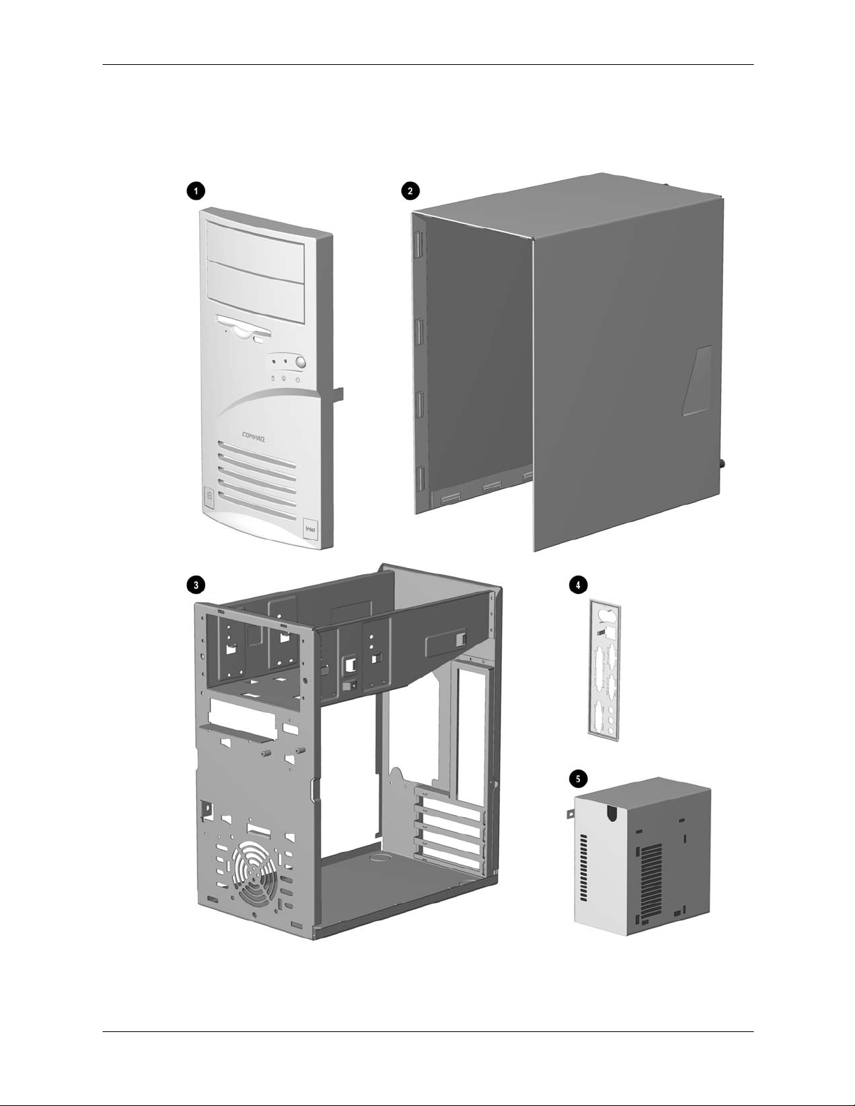
System Unit
Item Description Spare Part
1 Front Bezel with bezel blank and power button 149804-001
2 Hood sssembly 149800-001
3 Chassis not spared
4 System rear I/O panel 149805-001
5 Power supply 136337-001
Compaq Prosignia Desktop 340 Series Computer 2–3
Page 12
Spare Parts
2.2 Mass Storage Devices
2–4 Compaq Prosignia Desktop 340 Series Computer
Page 13

Mass Storage Devices
Spare Parts
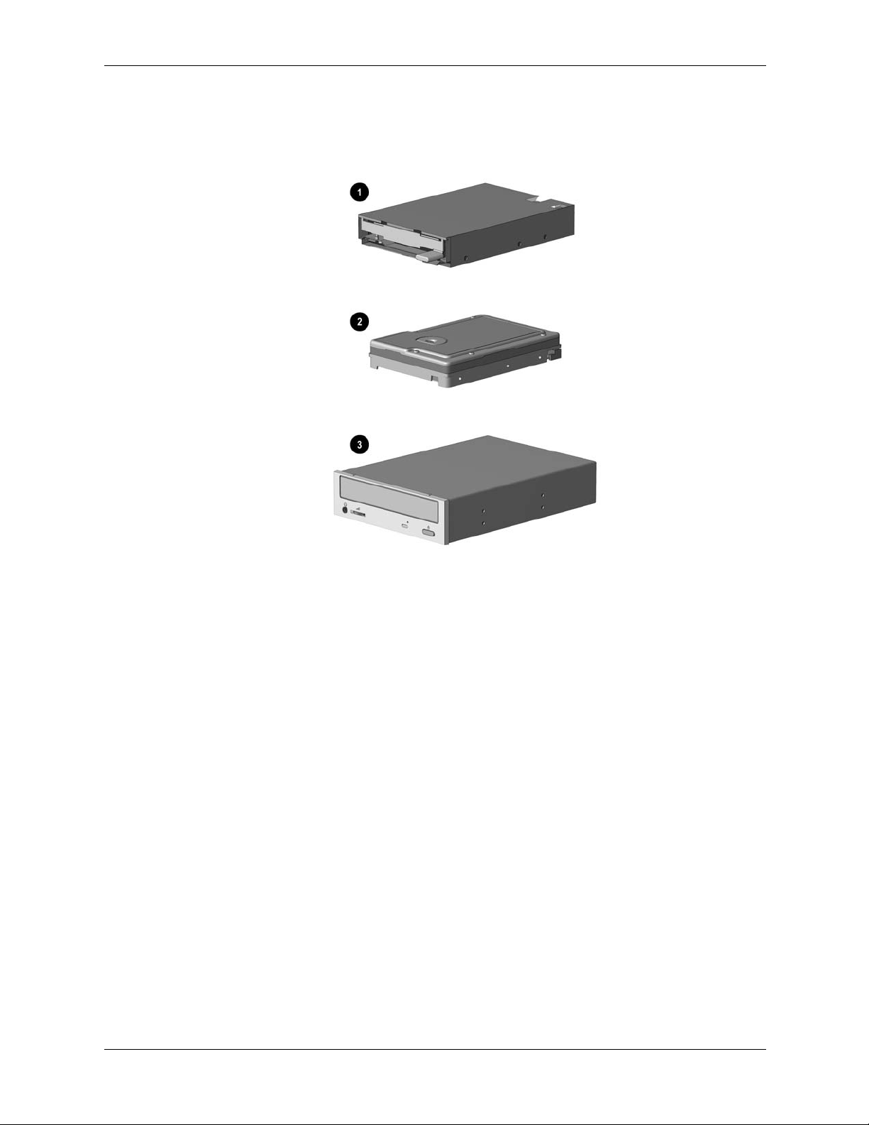
Item
1 Diskette drive 136338-001
Hard drive, 5400 RPM
2 4.3 GB 161431-001
* 8.4 GB 168027-001
* 13 GB, with mounting screws 161432-001
* 17 GB, with mounting screws 168591-001
Optical drives
3 8/4/32C CD-RW drive 294401-001
* 40X CD-ROM drive 400807-001
* 10X DVD drive with mounting screws 386128-001
* 10/40X DVD drive 161430-001
Other drives
* Zip 100 drive 386561-001
* Zip 250 drive 125776-001
*Not shown
Description
Spare Part
Compaq Prosignia Desktop 340 Series Computer 2–5
Page 14
Spare Parts
2.3 Cables
2–6 Compaq Prosignia Desktop 340 Series Computer
Page 15

Spare Parts
Cables
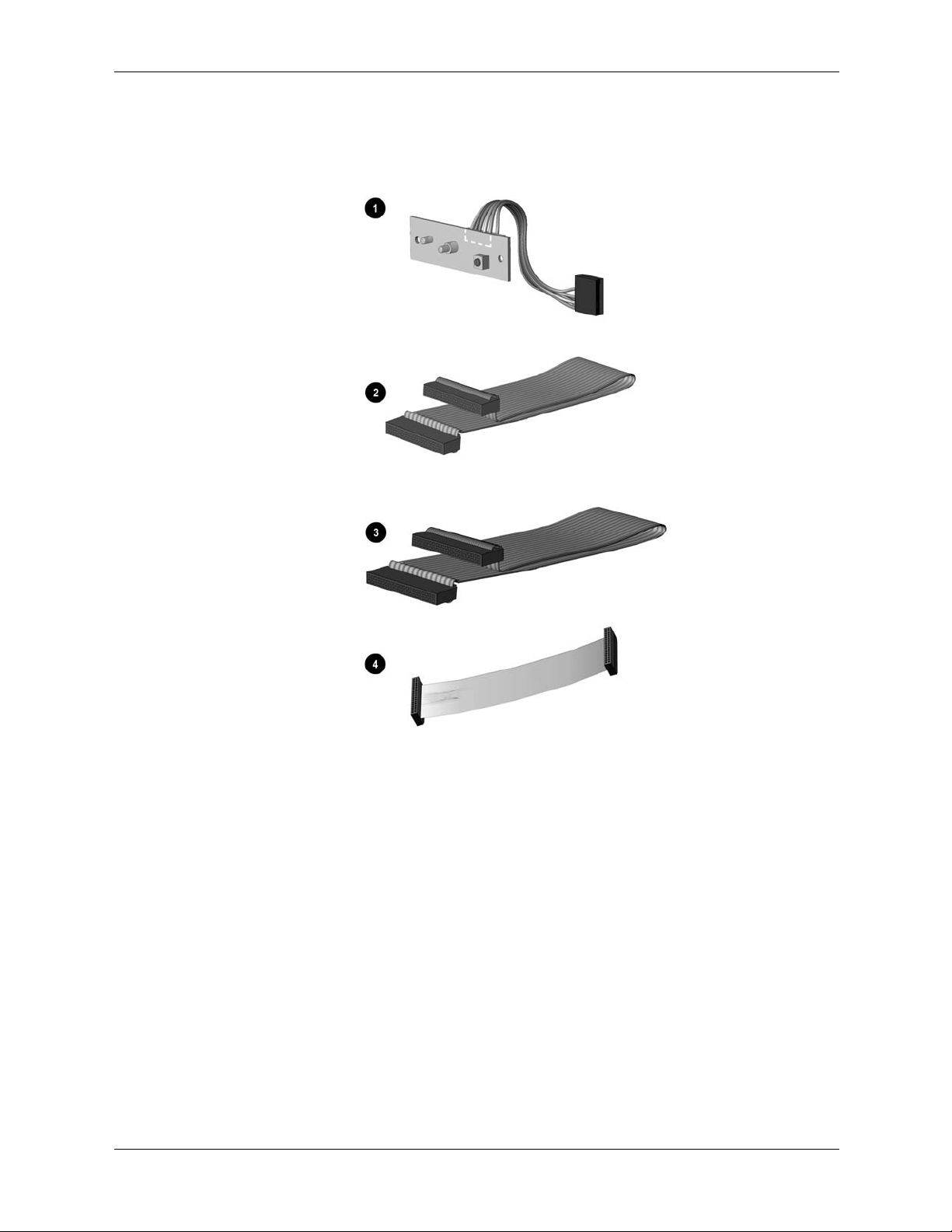
Item Description Spare Part
1 Power switch with cable and LEDs 136340-001
* Power cord, U.S. 142766 -001
Miscellaneous cable kit, includes 146019-001
2 Hard drive cable, 10.5” (108950-007)
* Diskette drive cable , 15.5”, (105875-001) (N/A this product)
* Dual LED/Power cable (387662-001) (N/A this product)
* Dual device hard drive cable (1308950-005) (N/A this product)
Miscellaneous cable kit, includes 298856-001
3 Optical drive cable, 14” (242947-001)
Diskette drive cable
4 Diskette drive cable 161735-001
Miscellaneous cable kit, includes 177707-001
* Audio cable, 21”, (288489-002)
* IDE cable, 12.5” (179048-001) (N/A this product)
* NIC wake up cable (179056-001) (N/A this product)
*Not shown
Compaq Prosignia Desktop 340 Series Computer 2–7
Page 16

Spare Parts
2.4 Standard and Optional Boards
2–8 Compaq Prosignia Desktop 340 Series Computer
Page 17

Spare Parts
Standard and Optional Boards
Item Description Spare Part
1 System board 187672-001
Intel processor with heatsink and heatsink retaining clip
2 466 MHz Celeron 174742-001
533 MHz Celeron 176220-001
550 MHz Pentium III 176221-001
600 MHz Pentium III 176222-001
Memory module
3 32 MB 166890-001
* 64 MB 179190-001
* 128 MB 166966-001
Modems
4 56K, V.90 International PCI modem 166358-002
* 56K PCI controllerless modem 167491-001
* 56K PCI controllerless modem 146803-001
Network Interface Cards
* PCI 10/100 Base-T NIC with remote wakeup 179167-001
* Intel Pro 10/100 NIC 116188-001
* Compaq 10/100 NIC 177454-001
* 11 MB/sec PCI wireless LAN 167132-001
*Not shown
Compaq Prosignia Desktop 340 Series Computer 2–9
Page 18

Spare Parts
2.5 Miscellaneous Parts
Miscellaneous Parts
Item Description Spare Part
1 Diskette drive mounting bracket 161734-001
2 Hard drive mounting bracket 149807-001
3 Two-button mouse 166861-001
* Option slot cover (5 ea) 304284-001
* Creative Labs SBS52 speakers, Australia 125773-011
* Creative Labs SBS52 speakers, Europe 125773-021
* Creative Labs SBS52 speakers, Japan 125773-391
* Creative Labs SBS52 speakers, U.K. 125773-031
* Creative Labs SBS52 speakers, U.S. 125773-001
* Altec ACS 233 speakers, Australia 135426-011
* Altec ACS 233 speakers, Europe 135426-021
* Altec ACS 233 speakers, Japan 135426-391
* Altec ACS 233 speakers, U.K. 135426-031
* Altec ACS 233 speakers, U.S. 135426-001
*Not shown
2–10 Compaq Prosignia Desktop 340 Series Computer
Page 19

Spare Parts
2.6 Keyboards
Keyboards (not illustrated)
Description Spare Part
Internet keyboard
Belgian 135510-181
French 135510-051
International 135510-B31
Spanish 135510-071
Swedish 135510-106
Swiss 135510-111
U.K. 135510-031
U.S. 135510-001
Spacesaver keyboard, Japanese 269513-291
2.7 Monitors
Monitors (not illustrated)
Size Description Spare Part
24” Model P1610 305710-001
21” Model P110 328267-001
17” Model P75 307815-001
21” Model V1000 351760-001
19” Model V900 303514-001
15” Model V500 308011-001
19” Model S900 360563-001
17” Model S700 360513-001
Compaq Prosignia Desktop 340 Series Computer 2–11
Page 20

Spare Parts
2–12 Compaq Prosignia Desktop 340 Series Computer
Page 21

3
Removal and Replacement Preliminaries and
Routine Care
This chapter provides general service information for the computer. Adherence to the procedures
and precautions described in this chapter is essential for proper service.
CAUTION: When the computer is plugged into an AC power source there is always voltage applied to
Ä
the system board. You must disconnect the power cord from the power source before opening the
computer to prevent system board or component damage.
3.1 Electrostatic Discharge Information
A sudden discharge of static electricity from your finger or other conductor can destroy
static-sensitive devices or microcircuitry. Often the spark is neither felt nor heard, but damage
occurs. An electronic device exposed to electrostatic discharge (ESD) may not be affected at all
and can work perfectly throughout a normal cycle. The device may function normally for a
while, then degrade in the internal layers, reducing its life expectancy.
Networks built into many integrated circuits provide some protection, but in many cases, the
discharge contains enough power to alter device parameters or melt silicon junctions.
3.1.1 Generating Static
The table below shows how different acti vities generate static electricity at different electrostatic
voltage levels.
Typical Electrostatic Voltages
Relative Humidity
Event 10% 40% 55%
Walking across carpet 35,000 V 15,000 V 7,500 V
Walking across vinyl floor 12,000 V 5,000 V 3,000 V
Motions of bench worker 6,000 V 800 V 400 V
Removing DIPs* from plastic tube 2,000 V 700 V 400 V
Removing DIPs* from vinyl tray 11,500 V 4,000 V 2,000 V
Removing DIPs* from Styrofoam 14,500 V 5,000 V 3,500 V
Removing bubble pack from PCB 26,500 V 20,000 V 7,000 V
Packing PCBs in foam-lined box 21,000 V 11,000 V 5,000 V
*Dual Inline Packaging (DIP) is the packaging around individual microcircuitry. These are then multipackaged inside plastic tubes, trays, or Styrofoam. 700 volts can degrade a product.
Compaq Prosignia Desktop 340 Series Computer 3–1
Page 22

Removal and Replacement Preliminaries and Routine Care
3.1.2 Preventing Electrostatic Damage to Equipment
Many electronic components are sensitive to ESD. Circuitry design and structure determine the
degree of sensitivity. The following proper packaging and grounding precautions are necessary to
prevent damage to electric components and accessories.
■ To avoid hand contact, transport products in static-safe containers such as tubes, bags, or boxes.
■
Protect all electrostatic parts and assemblies with conductive or approved containers or
packaging.
■ Keep electrostatic sensitive parts in their containers until they arrive at static-free stations.
■ Place items on a grounded surface before re moving them from their container.
■ Always be properly grounded when touching a sensitive component or assembly.
■ Avoid contact with pins, leads, or circuitry.
■ Place reusable electrostatic-sensitive parts from assemblies in protective packaging or
conductive foam.
3.1.3 Personal Grounding Methods and Equipment
Use the following equipment to prevent static electricity damage to equipment:
Wrist straps are flexible straps with a minimum of one-megohm +/- 10% resistance in the
ground cords. To provide proper ground, a strap must be worn snug against bare skin. The
ground cord must be connected and fit snugly into the banana plug connector on the grounding
mat or workstation.
Heel straps/Toe straps/Boot straps can be used at standing workstations and are compatible
with most types of shoes or boots. On conductive floors or dissipative floor mats, use them on
both feet with a minimum of one-megohm +/- 10% resistance between the operator and ground.
Static Shielding Protection Levels
Method Voltage
Antistatic plastic
Carbon-loaded plastic
Metallized laminate
1,500
7,500
15,000
3–2 Compaq Prosignia Desktop 340 Series Computer
Page 23

Removal and Replacement Preliminaries and Routine Care
3.1.4 Grounding Workstations
To prevent static damage at the workstation, use the following precautions:
■ Cover the workstation with approved static-dissipative material. Provide a wrist strap
connected to the work surface and properly grounded tools and equipment.
■ Use static-dissipative mats, foot straps, or air ionizers to give added protection.
■ Handle electrostatic sensitive components, parts, and assemblies by the case or PCB
laminate. Handle them only at static-free workstations.
■ Turn off power and input signals before inserting and removing connectors or test
equipment.
■ Use fixtures made of static-safe materials when fixtures must directly contact dissipative
surfaces.
■ Keep work area free of nonconductive materials, such as ordinary plastic assembly aids and
Styrofoam.
■ Use conductive field service tools, such as cutters, screwdrivers, and vacuums.
3.1.5 Recommended Materials and Equipment
Materials and equipment that are recommended for use in preventing static electricity include:
■ Antistatic tape
■ Antistatic smocks, aprons, or sleeve protectors
■ Co nductive bins and other assembly or soldering aids
■ Conductive foam
■ Co nductive tabletop workstations with ground cord of one-megohm +/- 10% resistance
■ Static-dissipative table or floor mats with hard tie to ground
■ Field service kits
■ Static awareness labels
■ Wrist straps and footwear straps providing one-megohm +/- 10% resistance
■ Material handling packages
■ Conductive plastic bags
■ Conductive plastic tubes
■ Conductive tote boxes
■ Opaque shielding bags
■ Transparent metallized shielding bags
■ Transparent shielding tubes
Compaq Prosignia Desktop 340 Series Computer 3–3
Page 24

Removal and Replacement Preliminaries and Routine Care
3.2 Routine Care
3.2.1 3.2.1 General Cleaning Safety Precautions
■ Never use solvents or flammable solutions to clean the computer.
■ Never immerse any parts in water or cleaning solutions, apply any liquids to a clean cloth
and then use the cloth on the component.
■ Always turn off the computer when cleaning with liquids or damp cloths.
■ Always turn off the computer before cleaning the keyboard, mouse, or air vents.
■ Disconnect the keyboard before cleaning it.
■ Wear safety glasses equipped with side shields when cleaning the keyboard.
3.2.2 Cleaning the Computer Case
Follow all safety precautions in Section 3.2.1 before cleaning the computer.
To clean the computer case, follow the procedures described below:
■ To remove light stains or dirt, use plain water with a clean, lint-free cloth or swab.
■ For stronger stains, use a mild dishwashing liquid diluted with water. Rinse well b y wiping it
with a cloth or swab dampened with clear water.
■ For stubborn stains, use isopropyl (rubbing) alcohol. No rinsing is needed as the alcohol will
evaporate quickly and not leave a residue.
■ After cleaning, always wipe the unit with a clean, lint-free cloth.
■ Occasionally , clean the air vents on the computer. Lint and other foreign matter can block the
vents and limit the airflow.
3.2.3 Cleaning the Keyboard
Follow all safety precautions in Section 3.2.1 before cleaning the keyboard.
To clean the tops of the keys or the keyboard body, follow the procedures described in Section
3.2.2.
When cleaning debris from under the keys, review all rules in Section 3.2.1 before following
these procedures:
CAUTION: Use safety glasses equipped with side shields before attempting to clean debris from under
Ä
the keys.
3–4 Compaq Prosignia Desktop 340 Series Computer
Page 25

■ Visible debris underneath or between the keys may be removed by vacuuming or shaking.
■ Canned, pressurized air may be used to clean debris from under the keys. Caution should be
used as too much air pressure can dislodge lubricants applied under the wide keys.
■ If you remove a key, use a specially designed key puller to prevent damage to the keys. This
tool is available through man y electroni c supply outlet s.
CAUTION: Never remove a wide leveled key (like the space bar) from the keyboard. If these keys are
Ä
improperly removed or installed, the keyboard may not function properly.
■ Cleaning under a key may be done with a swab moistened with isopropyl alcohol and
squeezed out. Be careful not to wipe away lubricants necessary for proper ke y functions. Use
tweezers to remove any fibers or dirt in confined areas. Allow the parts to air dry before
reassembly.
3.2.4 Cleaning the Monitor
■ Wipe the monitor screen with a clean cloth moistened with water or with a towlette designed
for cleaning monitors. Do not use sprays or aerosols directly on the screen; the liquid may
seep into the housing and damage a component. Never use so lvents or flammable liquids on
the monitor.
Removal and Replacement Preliminaries and Routine Care
■ To clean the monitor body follow the procedures in Section 3.2.2.
3.2.5 Cleaning the Mouse
Before cleaning the mouse, ensure that the power to the computer is turned off.
■ Clean the mouse ball by first removing the retaining plate and the ball from the housing. Pull
out any debris from the ball socket and wipe the ball with a clean, dry cloth before
reassembly.
■ To clean the mouse body, follow the procedures in Section 3.2.2.
3.3 Service Considerations
Listed below are some of the considerations that you should keep in mi nd during the disassembly
and assembly of the computer.
3.3.1 Tools and Software Requirements
To service the computer, you need the following:
■ Torx T-15 screwdriver (Compaq screwdriver, part number 161946-001)
■ Flat-bladed screwdriver
■ Diagnostics software
Compaq Prosignia Desktop 340 Series Computer 3–5
Page 26

Removal and Replacement Preliminaries and Routine Care
3.3.2 Screws
The screws used in the computer are not interchangeable. They may have standard or metric
threads and may be of different lengths. If an incorrect screw is used during the reassembly
process, it can damage the unit. Compaq strongly recommends that all screws removed during
disassembly be kept with the part that was removed, then returned to their proper locations.
3.3.3 Cables and Connectors
Most cables used throughout the unit are flat, flexible cables. These cables must be handled with
care to avoid damage. Apply only the tension required to seat or unseat the cables during
insertion or removal from the connector. Handle cables by the connector whenever possible. In
all cases, avoid bending, twisting, or tearing the cables, and ensure that the cables are routed in
such a way that they cannot be caught or snagged by parts being removed or replaced.
CAUTION: When servicing this computer, ensure that cables are placed in their proper
Ä
location during the reassembly process. Improper cable placement can damage the
computer.
3.3.4 Hard Drives
Handle hard drives as delicate precision components, avoiding all physical shock and vibration.
This applies to failed drives as well as replacement spares.
■ Use only the packaging provided by Compaq for shipping.
■ Do not rem ove hard drives from the shipping package for storage. Keep hard drives in their
protective packaging until they are actually mounted in the computer.
■ Avoid dropping drives from any height onto any surface.
3.3.5 Plastic Parts
Plastic parts can be damaged by the use of excessive force during disassembly and reassembly.
Use care when handling the plastic parts. Do not use a screwdri v er or similar tool to pry apart the
plastic components, use a flexible device, like a tongue depressor.
3.3.6 Lithium Battery
The lithium battery that comes with the computer is replaceable and should be properly disposed
of.
WARNING: Do not abuse or disassemble the lithium battery, as it may explode if
Å
mistreated. Do not disassemble, crush, puncture, short external contacts, dispose of in wa ter
or fire, or expose it to temperatures higher than 600C (1400F).
3–6 Compaq Prosignia Desktop 340 Series Computer
Page 27

Removal and Replacement Procedures
After completing all necessary removal and replacement procedures, run the Diagnostics utility
to verify that all components operate properly.
CAUTION: When the computer is plugged into an AC power source, there is always voltage applied to
Ä
the system board. You must disconnect the power cord from the power source before opening the
computer to prevent system board or component damage.
4.1 Preparation for Disassembly
See Chapter 3, “Removal and Replacement Preliminaries and Routine Care,” for initial
procedures.
To prepare the computer for disassembly:
1. Remove any diskette or compact disc from the computer.
2. Unlock the computer Smart Cover Lock using Computer Setup.
4
Turn off the computer and any peripheral devices that are connected to it.
CAUTION: Turn off the computer before disconnecting any cables.
Ä
CAUTION: When the computer is plugged into an AC power source, there is always voltage applied to
Ä
the system board. You must disconnect the power cord from the power source before opening the
computer to prevent system board or component damage.
3. Disconnect the power cord from the electrical outlet and then from the computer.
4. Disconnect all peripheral device cables from the computer.
During disassembly, label each cable as you remove it, noting its position and routing. Keep all
✎
screws with the units removed.
CAUTION: The screws used in the computer are of different thread sizes and lengths; using
Ä
the wrong screw in a component may damage the unit.
Compaq Prosignia Desktop 340 Series Computer 4–1
Page 28

Removal and Replacement Procedures
4.2 Hood
1. Prepare the computer for disassembly.
2. Unscrew the thumbscrews at the back of the computer.
The screws will remain attached to the hood.
✎
3. Grasp the bottom of the hood and pull back slightly while lifting the hood off the computer.
To replace the hood, reverse this sequence.
4–2 Compaq Prosignia Desktop 340 Series Computer
Page 29

4.3 Power Supply
1. Remove the hood.
2. Disconnect all cables connected to the power supply (cables to the hard drive, CD drive,
diskette drive, and system board).
3. Remove the four screws that secure the power supply to the rear of the chassis.
Removal and Replacement Procedures
4. Slide the power supply to the front of the unit and remove it from the chassis.
To replace the power supply, reverse this sequence.
Compaq Prosignia Desktop 340 Series Computer 4–3
Page 30

Removal and Replacement Procedures
4.4 Mass Storage Devices
Item Description
1 Optical drive
2
3
Diskette drive
Hard drive
4–4 Compaq Prosignia Desktop 340 Series Computer
Page 31

4.4.1 CD (Optical) Drive
If a compact disc is jammed in the drive, insert a straightened paper clip into the manual eject
hole and push firm1y.
Removal and Replacement Procedures
1. Perform the preparation procedures.
2. Remove the hood.
3. Disconnect the audio 1, data 2, and power 3 cables from the CD drive.
Compaq Prosignia Desktop 340 Series Computer 4–5
Page 32

Removal and Replacement Procedures
4. Remove the four screws from the side of the CD drive.
5. Pull the CD drive straight out of the front of the chassis.
To replace the CD drive, reverse this sequence.
4–6 Compaq Prosignia Desktop 340 Series Computer
Page 33

4.4.2 Diskette Drive
1. Perform the preparation procedures.
2. Remove the hood.
3. Remove the power supply. (Section 4.3)
Disconnect the power 1and data 2 cables from the diskette drive.
Removal and Replacement Procedures
Compaq Prosignia Desktop 340 Series Computer 4–7
Page 34

Removal and Replacement Procedures
4. Remove the screw that holds the diskette driv e and brack et to the chassis.
5. Grasp the drive bracket assembly on both sides and pull it towards the rear of the chassis.
6. Remove the four screws from the sides of the bracket to release the drive from the bracket.
To replace the diskette drive, reverse this sequence.
4–8 Compaq Prosignia Desktop 340 Series Computer
Page 35

4.4.3 Hard Drive
1. Perform the preparation procedures.
2. Remove the hood.
3. Disconnect the power 1 and signal 2 cables from the hard drive.
Removal and Replacement Procedures
4. Remove the screw holding the hard drive and bracket to the chassis.
5. Carefully push the hard drive and bracket towards the other side of the computer, and lift
them out of the chassis.
Compaq Prosignia Desktop 340 Series Computer 4–9
Page 36

Removal and Replacement Procedures
6. Remove the four screws at the bottom of the hard drive bracket to release the hard drive.
To replace the hard drive, reverse this sequence.
4–10 Compaq Prosignia Desktop 340 Series Computer
Page 37

4.5 Video Card
1. Perform the preparation procedures.
2. Remove the hood.
3. Remove the screw holding the video card bracket to the chassis, and pull the video card out
of the slot.
Removal and Replacement Procedures
To replace the video card, reverse this sequence.
Compaq Prosignia Desktop 340 Series Computer 4–11
Page 38

Removal and Replacement Procedures
4.6 Network Card
1. Perform the preparation procedures.
2. Remove the hood.
3. Remove the screw holding the network card bracket to the chassis, and pull the network card
out of the slot.
To replace the network card, reverse this sequence.
4–12 Compaq Prosignia Desktop 340 Series Computer
Page 39

4.7 Fax/Modem Card
1. Perform the preparation procedures.
2. Remove the hood.
3. Remove the screw holding the fax/modem bracket to the chassis, and pull the fax/modem
card out of the slot.
Removal and Replacement Procedures
To replace the fax/modem card, reverse this sequence.
CAUTION: When replacing the fax/modem, download the latest SoftPaq containing the software from
Ä
www.compaq.com. If QuickRestore is used, it may not have the 56K upgrade software included.
Compaq Prosignia Desktop 340 Series Computer 4–13
Page 40

Removal and Replacement Procedures
4.8 Memory Module
1. Perform the preparation procedures.
2. Remove the hood.
3. Remove the power supply.
4. Release the latches 1 at each end of the DIMM socket and unplug the DIMM 2 from the
system board.
To replace the memory module, reverse this sequence.
4–14 Compaq Prosignia Desktop 340 Series Computer
Page 41

4.9 RTC Battery
WARNING: This computer contains an internal lithium battery. There is a risk of fire and burns if the
Å
battery is not handled properly. To reduce the risk of personal injury:
- Do not attempt to recharge the battery.
- Do not expose to temperatures higher than 140 F (60 C).
- Do not disassemble, crush, puncture, short circuit contacts, ordispose of in fire or water.
- Replace battery only with the Compaq spare designated for this product.
1. Perform the preparation procedures.
2. Remove the hood.
3. Remove the power supply. (Section 4.3)
4. Remove the diskette drive. (Section 4.4.2)
5. Locate the RTC battery.
6. Release the retaining tab and push the battery forward, up, and out of the battery retainer.
Removal and Replacement Procedures
To replace the RTC battery, reverse this sequence.
Compaq Prosignia Desktop 340 Series Computer 4–15
Page 42

Removal and Replacement Procedures
4.10 Processor
1. Perform the preparation procedures.
2. Remove the hood.
3. Remove the power supply. (Section 4.3)
4. Locate the heatsink 2 on the system board.
5. Remove the clip 1 from the heatsink.
6. Carefully remove the heatsink from the processor 4 by twisting it before lifting it from the
socket (the two are held together by an adhesive strip
from the processor as it may pull the processor from its socket and damage its pins.
7. Tilt the ZIF socket handle 5 away from the system board.
8. Lift the processor directly out of the ZIF socket.
To replace the processor, rev e rs e this sequ ence.
8). Never lift the heatsink straight up
4–16 Compaq Prosignia Desktop 340 Series Computer
Page 43

4.11 Front Bezel
1. Perform the preparation procedures.
2. Remove the hood.
3. Release the latches at the middle and bottom of the bezel, then pivot the bezel up and away
from the chassis.
Removal and Replacement Procedures
To replace the front bezel, reverse this sequence.
Compaq Prosignia Desktop 340 Series Computer 4–17
Page 44

Removal and Replacement Procedures
4.12 On-Button Board
1. Perform the preparation procedures.
2. Remove the hood.
3. Remove the front bezel. (Section 4.11)
4. Disconnect the on-button board connector from the system board.
5. Remove the two screws from the button board assembly, and pull the board off the chassis.
To replace the on-button board, reverse this sequence.
4–18 Compaq Prosignia Desktop 340 Series Computer
Page 45

4.13 System Board Bracket
1. Perform the preparation procedures.
2. Remove the hood.
3. Remove the modem.
4. Remove the network card.
5. Remove the video card.
6. Remove the screws holding the system board bracket to the chassis.
Removal and Replacement Procedures
7. Slide the system board bracket toward the front bezel and carefully pull the bracket away
from the chassis.
8. Disconnect the CD audio cable and data cable from the system board.
9. Disconnect the cables for the hard drive data, diskette drive, and power button from the
system board.
10. To replace the system board bracket, reverse this sequence.
CAUTION: When reinstalling the system board bracket, ensure that the fingers of the I/O panel are
Ä
properly aligned to prevent them from being bent. If the fingers become bent, the system board may get
damaged.
Compaq Prosignia Desktop 340 Series Computer 4–19
Page 46

Removal and Replacement Procedures
4.14 System Board
1. Perform the preparation procedures.
2. Remove the hood.
3. Remove the system board bracket. (Section 4.13)
4. Remove all of the cables from the system board.
5. Remove the eight screws that secure the system board to the bracket.
To replace the system board, reverse this sequence.
4–20 Compaq Prosignia Desktop 340 Series Computer
Page 47

4.15 1/O Panel
1. Perform the preparation procedures.
2. Remove the hood.
3. Remove the system board bracket.
4. Gently push the I/O panel into the chassis from the rear of the unit.
Removal and Replacement Procedures
To replace the I/O panel, reverse this sequence.
Compaq Prosignia Desktop 340 Series Computer 4–21
Page 48

Removal and Replacement Procedures
4–22 Compaq Prosignia Desktop 340 Series Computer
Page 49

System Board Jumpers and Switches
5.1 System Board Jumpers and Switches
5
Jumpers and Switches
Item Description Item Description
BT1 Real-Time clock battery socket J35 Wake on LAN connector
CMOS CMOS reset button J36 Password jumper
DIMM1 Memory module socket 1 J37 Power switch/LED cable connector
DIMM2 Memory module socket 2 J38 Internal speaker connector
J9 Power supply connector J39 Boot block jumper
J12 IDE (ATA) drive connector, primary J40 SCSI LED connector
J13 IDE (ATA) drive connector, secondary PCI1 PCI expansion slot
J14 Diskette drive connector PCI2 PCI expansion slot
J15 Heatsink fan connector PCI3 PCI expansion slot
J17 CD-ROM audio connection PCI4 PCI expansion slot
J32 Firmware jumper (do not use) Processor socket
J33 Firmware jumper (do not use)
Compaq Prosignia Desktop 340 Series Computer 5–1
Page 50

System Board Jumpers and Switches
5.2 Clearing and Setting Passwords
Setting the Password provides access protection for the Computer Setup utility.
Follow the instructions below to clear the password.
1. Turn off the computer and any external devices.
2. Disconnect the power cord from the power outlet.
WARNING: The power cord must be disconnected from the power source before removing the access
Å
panel. Stray voltage on the system board may injure you.
3. Remove the access panel.
4. Remove the jumper from header J36 from pins 1 and 2. Place the jumper on pin 2 only, in
order to avoid losing it.
5. Replace the access panel.
6. Reconnect the power cord and the external equipment
7. Turn the computer on and allow the system to start. This clears the current password and
disables the password features.
To establish a new password after the old password has been cleared, follow the instructions
below.
1. Turn off the computer and any external devices.
2. Disconnect the power cord from the power outlet.
3. Remove the jumper from header J36 from pin 2. Place the jumper on pins 1 and 2 only.
4. Replace the access panel.
5. Reconnect the power cord and the external equipment
6. Turn the computer on and allow the system to start. Go to Computer Setup (GF10) to
establish the new password.
5–2 Compaq Prosignia Desktop 340 Series Computer
Page 51

5.3 Resetting CMOS
The computer's configuration (CMOS) may occasionally be corrupted. If it is, it is necessary to
clear the CMOS memory using the CMOS button on the system board. To clear and reset the
configuration, perform the following procedure:
1. Prepare the computer for disassembly.
2. Disconnect the power cord from the power outlet.
3. Remove the access panel.
WARNING: The power cord must be disconnected from the power source before removing the access
Å
panel. Stray voltage on the system board may injure you.
4. Press the CMOS button located on the system board and keep it depressed for 5 seconds.
5. Replace the access panel.
6. Reconnect the power cord.
7. Turn the computer on.
8. Run the Computer Setup (F10) utility to reconfigure the system.
System Board Jumpers and Switches
When the CMOS button is pushed the password becomes in valid because it is stored
✎
in the configuration memory. You will need to reset the password.
CAUTION: The power cord must be disconnected from the power source before pushing the CMOS
Ä
Button. Failure to do so may damage the system board.
Compaq Prosignia Desktop 340 Series Computer 5–3
Page 52

System Board Jumpers and Switches
5–4 Compaq Prosignia Desktop 340 Series Computer
Page 53

Index
A
access panel removal and replacement 4–2
audio cable spare part number
2–7
B
battery 3–6
removal and replacement
safety precautions
bezel blank spare parts number
3–6
4–15
2–3
C
cables spare part number 2–7
CD-ROM cable spare part number
CD-ROM drive removal and replacement
CD-ROM drive spare part number
chassis
spare part number
cleaning
computer
keyboard
monitor
mouse
safety precautions
cleaning the keyboard
clearing password
CMOS setting
computer cleaning
connectors, rear panel
3–4
3–4
3–5
3–5
5–3
2–3
3–4
3–4
5–2
3–4
1–3
2–7
2–5
D
disassembly preparation 4–1
diskette drive
cable spare part number
mounting bracket spare part number
removal and replacement
spare part number
drive location
DVD cable spare part number
DVD drive spare part number
4–4
2–7
2–10
4–7
2–5
2–7
2–5
E
electrostatic discharge 3–1
expansion card removal and replacement
4–12, 4–13
4–5
4–11,
expansion card spare part number
2–8
F
fax/modem card removal and replacement 4–13
front bezel removal and replacement
front bezel spare part number
front panel controls and LEDs
2–3
4–17
1–2
G
generating static electriciity 3–1
grounding guidelines
grounding methods
3–2
3–3
H
hard drive
cable spare part number
mounting bracket spare part number
safety precautions
spare part number
hard drive removal and replacement
hood assembly, spare part number
hood removal and replacement
2–7
2–10
3–6
2–5
4–7, 4–9
2–3
4–2
I
I/O panel removal and replacement 4–21
I/O panel spare part number
2–3
K
keyboard cleaning 3–4
keyboard spare part number
2–11
M
memory module removal and replacement 4–14
memory module spare part number
microprocessor removal and replacement
microprocessor spare part number
monitor cleaning
monitor spare part number
mother board removal and replacement
mouse cleaning
mouse spare part number
3–5
2–11
3–5
2–10
2–9
4–16
2–9
4–20
N
Network Interface Card (NIC) removal and
replacement
4–12
Compaq Prosignia Desktop 340 Series Computer Index–1
Page 54

Index
Network Interface Card (NIC) spare part number
2–9
O
On-button board removal and replacement 4–18
optical drive cable spare part number
optical drive removal and replacement
option slot cover spare part number
2–7
4–5
2–10
P
password setting and clearing 5–2
plastic parts safety precautions
power button/LED cable removal and replacement
4–18
power cord spare part number
power supply removal and replacement
power supply spare part number
power switch/LED cable spare part number
preparation for disassembly
preventing static electricity damage
processor removal and replacement
processor spare part number
3–6
2–7
4–3
2–3
2–7
4–1
3–2
4–16
2–9
R
rear panel connectors 1–3
removal and replacement
access panel
battery
diskette drive
DR-ROM drive
expansion card
fax/modem card
front bezel
hard drive
4–2
hood
I/O panel
memory module
microprocessor
mother board
Network Interface Card (NIC)
On-button board
optical drive
power button/LED cable assembly
power supply
preparation
processor
RTC battery
system board
system board bracket
video card
RTC battery removal and replacement
4–2
4–15
4–7
4–5
4–11, 4–12
4–13
4–17
4–7, 4–9
4–21
4–14
4–16
4–20
4–12
4–18
4–5
4–18
4–3
4–1
4–16
4–15
4–20
4–19
4–11
4–15
S
safety precautions 3–6
cleaning
hard drives
plastic parts
screws used
serial number location
service tools required
setting CMOS
setting password
spare part number
audio cable
bezel blank
cables
2–7
CD-ROM cable
CD-ROM drive
diskette drive
diskette drive cable
diskette drive mounting bracket
drives
2–4
DVD cable
DVD drive
expansion boards
front bezel
hard drive
hard drive cable
hard drive mounting bracket
hood assembly
I/O panel
keyboard
mass storage devices
memory module
microprocessor
monitor
mouse
Network Interface Card (NIC)
optical drive
optical drive cable
other drive
power cord
power supply
power switch/LED cable
processor
speaker
standard and optional boards
storage devices
system board
system unit
Zip drive
2–11
2–10
2–10
3–4
3–6
3–6
3–6
1–4
3–5
5–3
5–2
2–7
2–3
2–7
2–5
2–5
2–7
2–10
2–7
2–5
2–8
2–3
2–5
2–7
2–10
2–3
2–3
2–11
2–4
2–9
2–9
2–9
2–5
2–7
2–5
2–7
2–3
2–7
2–9
2–8
2–4
2–9
2–3
2–5
Compaq Prosignia Desktop 340 Series Computer Index–2
Page 55

Index
spare part number, chassis 2–3
speaker spare part number
standard and optional boards spare part number
static electricity
storage devices, location
switches, system board
system board
bracket removal and assembly
jumpers and switches
removal and replacement
3–1
2–10
4–4
5–1
4–19
5–1
4–20
2–8
spare part number
system unit spare part numbers
2–9
2–3
T
tools required, service 3–5
V
video card removal and replacement 4–11
Z
Zip drive, spare part number 2–5
Compaq Prosignia Desktop 340 Series Computer Index–3
Page 56

Index
Compaq Prosignia Desktop 340 Series Computer Index–4
 Loading...