

Page 1
MAINTENANCE & SERVICE GUIDE
PROSIGNIA NOTEBOOK 190
INDEX PAGE PRODUCT DESCRIPTION LEGAL NOTICE HOW TO USE THIS GUIDE
REMOVAL & REPLACEMENT ILLUSTRATED PARTS CATALOG TROUBLESHOOTING SPECIFICATIONS
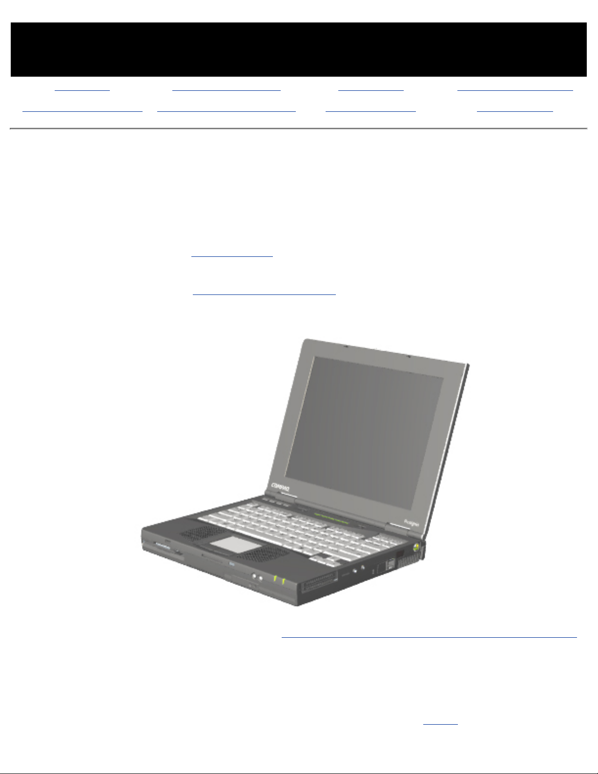
Welcome to the Maintenance & Service Guide (MSG) for
the
Compaq Prosignia Notebook 190 Family.
This is an online guide designed to serve the needs of those whose job it is to repair
Compaq products.
Please first read the Legal Notice which contains copyright and trademark
information.
Then read the section on How to use this guide , which shows symbol conventions,
technician notes, and the serial number location for the unit.
Click here for information on the computer's battery pack operating time (Power Management).
Click here to download the complete ZIP file (3.5 MB) of this Maintenance & Service
Guide to your hard drive.
This MSG will be periodically maintained and updated as needed.
To report a technical problem, contact your Regional Support Center or IM Help Center.
For content comments or questions, contact the Editor.
Page 2

Page 3
MAINTENANCE & SERVICE GUIDE
PROSIGNIA NOTEBOOK 190
INDEX PAGE PRODUCT DESCRIPTION LEGAL NOTICE HOW TO USE THIS GUIDE
REMOVAL & REPLACEMENT ILLUSTRATED PARTS CATALOG TROUBLESHOOTING SPECIFICATIONS
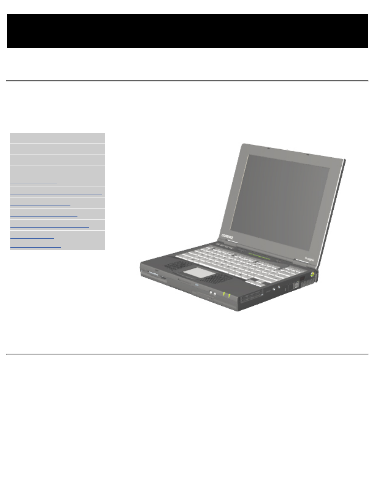
Product Description
Index Page
>Models
>Top Cover
>Top Lights
>Left & Front
Components
>Right side Components
>Bottom of Unit
>Rear Connectors
>Power Management
>Intelligent
Manageability
Compaq Prosignia Notebook 190
Page 4

MAINTENANCE & SERVICE GUIDE
PROSIGNIA NOTEBOOK 190
INDEX PAGE PRODUCT DESCRIPTION LEGAL NOTICE HOW TO USE THIS GUIDE
REMOVAL & REPLACEMENT ILLUSTRATED PARTS CATALOG TROUBLESHOOTING SPECIFICATIONS
Legal Notice
The information in this guide is subject to change without notice.
COMPAQ COMPUTER CORPORATION SHALL NOT BE LIABLE FOR TECHNICAL OR EDITORIAL
ERRORS OR OMISSIONS CONTAINED HEREIN, NOR FOR INCIDENTAL OR CONSEQUENTIAL
DAMAGES RESULTING FROM THE FURNISHING, PERFORMANCE, OR USE OF THIS MATERIAL.
This guide contains information protected by copyright. No part of this guide may be
photocopied or reproduced in any form without prior written consent from Compaq Computer
Corporation.
Copyright 2000 Compaq Computer Corporation.
All rights reserved. Printed in the U.S.A.
Compaq, Prosignia Series Registered U. S. Patent and Trademark Office.
Microsoft, MS-DOS, and Windows are registered trademarks of Microsoft Corporation.
The software described in this guide is furnished under a license agreement or nondisclosure
agreement. The software may be used or copied only in accordance with the terms of the
agreement.
Product names mentioned herein may be trademarks and/or registered trademarks of their
respective companies.
Maintenance and Service Guide
Compaq Prosignia Notebook 190 Family
Third Edition (April 2000)
Compaq Computer Corporation
Page 5
MAINTENANCE & SERVICE GUIDE
PROSIGNIA NOTEBOOK 190
INDEX PAGE PRODUCT DESCRIPTION LEGAL NOTICE HOW TO USE THIS GUIDE
REMOVAL & REPLACEMENT ILLUSTRATED PARTS CATALOG TROUBLESHOOTING SPECIFICATIONS
How to use this Guide
Preface
This Maintenance and Service Guide is a troubleshooting guide that can be used for reference when servicing the Compaq
Prosignia 190.
Compaq Computer Corporation reserves the right to make changes to the Compaq Prosignia Notebook Family of Computers
without notice.
Symbols
The following words and symbols mark special messages throughout this guide:
WARNING: Text set off in this manner indicates that failure to follow directions in the warning could result in
bodily harm or loss of life.
CAUTION: Text set off in this manner indicates that failure to follow directions could result in damage to
equipment or loss of data.
IMPORTANT:
Text set off in this manner presents clarifying information or specific instructions.
NOTE:
Text set off in this manner presents commentary, sidelights, or interesting points of information.
Technician Notes
WARNING: Only authorized technicians trained by Compaq should repair this equipment. All troubleshooting
and repair procedures are detailed to allow only subassembly/module level repair. Because of the complexity
of the individual boards and subassemblies, the user should not attempt to make repairs at the component
level or to make modifications to any printed circuit board. Improper repairs can create a safety hazard. Any
indications of component replacement or printed circuit board modifications may void any warranty
Serial Number
When requesting information or ordering spare parts, the computer's serial number should be provided to Compaq. The
serial number is located on the bottom of the computer.
Locating Additional Information
The following documentation is available to support this product:
Compaq Prosignia 190 Notebook documentation set●
Introducing Windows 98 Guide●
Introducing Windows 2000 Professional Guide●
Service Training Guides●
Compaq Service Advisories and Bulletins●
Page 6

Compaq QuickFind●
Compaq Service Quick Reference Guide●
Page 7

MAINTENANCE & SERVICE GUIDE
PROSIGNIA NOTEBOOK 190
INDEX PAGE PRODUCT DESCRIPTION LEGAL NOTICE HOW TO USE THIS GUIDE
REMOVAL & REPLACEMENT ILLUSTRATED PARTS CATALOG TROUBLESHOOTING SPECIFICATIONS
Removal & Replacement
Index Page
Removal & Replacement Preliminaries
Removal & Replacement Procedures
Page 8

MAINTENANCE & SERVICE GUIDE
PROSIGNIA NOTEBOOK 190
INDEX PAGE PRODUCT DESCRIPTION LEGAL NOTICE HOW TO USE THIS GUIDE
REMOVAL & REPLACEMENT ILLUSTRATED PARTS CATALOG TROUBLESHOOTING SPECIFICATIONS
Illustrated Parts Catalog
Index Page
This section helps identify part numbers associated with each item(s) for the Compaq Prosignia
Notebook 190 Family. These are the numbers used in ordering replacement parts.
System Unit
Mass Storage Devices
Miscellaneous Parts
Documentation & Software
Page 9

MAINTENANCE & SERVICE GUIDE
PROSIGNIA NOTEBOOK 190
INDEX PAGE PRODUCT DESCRIPTION LEGAL NOTICE HOW TO USE THIS GUIDE
REMOVAL & REPLACEMENT ILLUSTRATED PARTS CATALOG TROUBLESHOOTING SPECIFICATIONS
Troubleshooting
Index Page
Follow these basic steps when beginning the troubleshooting process:
Complete the Preliminary steps.1.
Run the Power-On Self-Test (POST).2.
Check Compaq Utilities (F10 Setup).3.
If you are unable to run POST or if the problem persists after running POST, perform the
recommended actions described in the Troubleshooting without Diagnostics section.
Follow these guidelines when troubleshooting:
Complete the recommended actions in the order in which they are given.
●
Repeat POST after each recommended action until the problem is resolved and the error
message does not return.
●
When the problem is resolved, stop performing the troubleshooting steps and do not
complete the remaining recommended actions.
●
Refer to the removal and replacement procedures.●
NOTE:
If the problem is intermittent, check the computer several times to verify
that the problem is solved.
Page 10

MAINTENANCE & SERVICE GUIDE
PROSIGNIA NOTEBOOK 190
INDEX PAGE PRODUCT DESCRIPTION LEGAL NOTICE HOW TO USE THIS GUIDE
REMOVAL & REPLACEMENT ILLUSTRATED PARTS CATALOG TROUBLESHOOTING SPECIFICATIONS
Specifications
Index Page
This chapter covers the following specifications of Compaq Prosignia Series Portable
Computers.
Click on a link to go to a particular specification:
Physical & Environmental
Display
Hard Drives
CD/DVD Drives
Diskette Drive
Battery Pack
Modem
System Memory
System Interrupts
System DMA
System I/O
Pin Assignments
Page 11

MAINTENANCE & SERVICE GUIDE
PROSIGNIA NOTEBOOK 190
INDEX PAGE PRODUCT DESCRIPTION LEGAL NOTICE HOW TO USE THIS GUIDE
REMOVAL & REPLACEMENT ILLUSTRATED PARTS CATALOG TROUBLESHOOTING SPECIFICATIONS
Specifications
Physical & Environmental
>Physical &
Environmental
>Display
>Hard Drives
>CD/DVD
Drives
>Diskette
Drive
>Battery Pack
>Modem
>System
Memory
>System
Interrupts
>System DMA
>System I/O
>Pin
Assignments
U.S. Metric
Dimensions
Height
Depth
Width
12.4 in.
9.99 in.
1.6 in.
31.5 cm
25.3 cm
4.1 cm
Weight
6.0 to 7.0 lbs
2.72 to 3.17
kg
Battery
Nominal operating
voltage (Li-Ion)
Average operating
Peak operating power
10.8 V DC
15W avg.
30W peak
AC Adapter Power Requirements
Power Supply 100-120/220-240
Rated Input Voltage
90 to 264 VAC
(auto-switching)
1.2/0.6 Amp
Rated Input Current
< 60W
50 to 60 Hz AC
Rated Frequency
47 to 63 Hz
+18.85 volts
1kV for 50 ns
Temperature
Operating
Nonoperating
50 to 104°F
-4 to 140°F
10° to 35°C
-20 to 60°C
Relative Humidity
(noncondensing)
Operating
Nonoperating
10 to 90%
5 to 95%, 101.6°F/38.7°C
Maximum wetbulb
temperature
Altitude
(nonpressurized
environment)
Operating
Nonoperating
0 to 10,000 ft
0 to 30,000 ft
0 to 3048 m
0 to 9144 m
Page 12

Shock
Operating
Nonoperating
10 G, 11 ms, half sine
240 G, 2 ms, half sine
Vibration
Operating
Nonoperating
0.5 G zero-to-peak, 10 to
500 Hz, 0.25 oct/min
1.5 G, zero-to-peak, 10 to
500 Hz, 0.5 oct/min
Page 13

MAINTENANCE & SERVICE GUIDE
PROSIGNIA NOTEBOOK 190
INDEX PAGE PRODUCT DESCRIPTION LEGAL NOTICE HOW TO USE THIS GUIDE
REMOVAL & REPLACEMENT ILLUSTRATED PARTS CATALOG TROUBLESHOOTING SPECIFICATIONS
Specifications
Display
>Physical &
Environmental
>Display
>Hard Drives
>CD/DVD
Drives
>Diskette
Drive
>Battery Pack
>Modem
>System
Memory
>System
Interrupts
>System DMA
>System I/O
>Pin
Assignments
14.1-Inch Color TFT XGA Display
U.S. Metric
Viewable Dimensions
Height
Width
Diagonal
11.22 in.
8.46 in.
14.1 in.
28.5 cm
21.5 cm
35.81 cm
Number of Colors
up to 16.8 million
Contrast Ratio
150:1
Brightness
120 nits 150nt typ
Pixel Resolution
Pitch
Format
Configuration
0.264 × 0.264 mm
1024 × 768
RGB Stripe
Backlight
Edge-Lit
Character Display
80 × 25
Total Power
Consumption
4.2 W
12.1-Inch Color TFT SVGA Display
U.S. Metric
Viewable Dimensions
Height
Width
Diagonal
9.7 in.
7.24 in.
12.1 in
24.6 cm
18.4 cm
30.7 cm
Number of Colors
up to 16.8 million
Contrast Ratio
150:1
Brightness
120 nits 150nt typ
Pixel Resolution
Pitch
Format
Configuration
0.30 x 0.30 mm
800 x 600 RGB Stripe
Backlight
Edge-Lit
Character Display
80 × 25
Total Power
Consumption
3.5W
Page 14

Page 15

MAINTENANCE & SERVICE GUIDE
PROSIGNIA NOTEBOOK 190
INDEX PAGE PRODUCT DESCRIPTION LEGAL NOTICE HOW TO USE THIS GUIDE
REMOVAL & REPLACEMENT ILLUSTRATED PARTS CATALOG TROUBLESHOOTING SPECIFICATIONS
Specifications
Hard Drives
>Physical &
Environmental
>Display
>Hard Drives
>CD/DVD
Drives
>Diskette
Drive
>Battery Pack
>Modem
>System
Memory
>System
Interrupts
>System DMA
>System I/O
>Pin
Assignments
6 GB 12 GB 18 GB
User capacity per
drive
6.4 GB 12 GB 12 GB
Drive type
65 65 65
Drive height
Drive width
0.5 in/12.5
mm
2.75 in/7 mm
0.5 in/12.5
mm
2.75 in/77
mm
.5 in./12.5
mm
2.75 in./70
mm
Interface type
ATA ATA ATA
Seek times (typical,
including settling)
Single track
Average
Full stroke
3 ms
13 ms
25 ms
2.5 ms
12 ms
23 ms
2 ms
12 ms
23 ms
Physical
configuration
Cylinders
Heads
Sectors per track
Bytes per sector
9279
6
63
512
23,392
16
63
512
35,152
16
63
512
Logical
configuration
Cylinders
Heads
Sectors per track
12,416
15
63
13424
16
63
16383
16
63
Transfer rate
Media
Interface
86.4 to 153.3
MB/s
UDMA 33.3
MB/s
85.5 to
161.6
MB/s
UDMA 33.3
MB/s
85.5 to 161.1
MB/s
UDMA 33.3
MB/s
Page 16

MAINTENANCE & SERVICE GUIDE
PROSIGNIA NOTEBOOK 190
INDEX PAGE PRODUCT DESCRIPTION LEGAL NOTICE HOW TO USE THIS GUIDE
REMOVAL & REPLACEMENT ILLUSTRATED PARTS CATALOG TROUBLESHOOTING SPECIFICATIONS
Specifications
CD & DVD Drives
>Physical &
Environmental
>Display
>Hard Drives
>CD/DVD
Drives
>Battery Pack
>Modem
>System
Memory
>System
Interrupts
>System DMA
>System I/O
>Pin
Assignments
24X CD-ROM Drive
Applicable Disc
CD-ROM
Applicable Disc CD-ROM
(Mode 1, 2 and 3), CD-XA
ready (Mode 2, Form 1 and
2), CD-I ready (Mode 2, Form
1 and 2), CD-R (read only),
CD Plus, Photo CD (Single
and Multi-session),
CD-Extra, Video CD, CD-WO
(fixed packets only),
CD-Bridge
Center Hole Diameter
.59 in./15 mm
Disc Diameter
12 cm, 8 cm
Disc Thickness
1.2 mm
Track Pitch
1.6 µm
Access Time
Random
Full Stroke
< 150 ms
< 300 ms
Audio Output Level
Line Out
0.7 V rms
Cache Buffer
128 KB
Data Transfer Rate
Sustained, 16X
Variable
Normal PIO Mode 4
(single burst)
Startup time
Stop time
2400 KB/s (150 KB/s at 1X)
1500 to 3600 KB/sec
16.6 MB/sec
< 8.0 seconds
< 4.0 seconds
8X DVD-ROM Drive
Page 17

Applicable Disc
DVD-5, DVD-9, DVD-10
CD-ROM mode 1, mode 2
CD-Digital Audio
CD-XA mode (Form 1, Form
2)
CD-I Ready
CD-Bridge
CD-R
Photo CD
(single/multisession)
Center Hole Diameter
.59 in./15 mm
Disc Diameter
12 cm, 8 cm
Disc Thickness
1.2 mm
Track Pitch
.74 m
Access Time
Random
Full Stroke
< 150 ms
< 225 ms
Audio Output Level
Line Out
Headphone
0.7 V rms
none
Cache Buffer
128 KB
Data Transfer Rate
Sustained, 1x CD rate
Sustained, 16x CD rate
Sustained, 1x DVD rate
Sustained, 4x DVD rate
Normal IO Mode 4 (single
burst)
150 KB/sec
2400 KB/sec
1380 KB/sec
5520 KB/sec
16.6 MB/sec
Startup Time
< 15 seconds
Stop time
< 6 seconds
4X DVD-ROM Drive
Applicable Disc
DVD-ROM, CD-ROM, CD-XA,
CD-I, Photo CD,
Multi-session, Audio, CD-R,
CD-RW
Center Hole Diameter
.59 in./39 cm
Disc Diameter
12 cm/ 8 cm
Disc Thickness
1.2 mm
Page 18

Track Pitch
.74 µm
Access Time
Random
Full Stroke
< 150 ms
< 225 ms
Audio Output Level
Line Out
0.7 V rms
Cache Buffer
128 KB
Data Transfer Rate
Sustained, 16x CD rate
Sustained, 4x DVD
Normal PIO Mode 4
(single burst)
2400 KB/s (150 KB/sec at
1X)
5520 KB/sec
16.6 MB/sec
Startup Time
Stop time
< 15 seconds
< 6 seconds
Page 19

MAINTENANCE & SERVICE GUIDE
PROSIGNIA NOTEBOOK 190
INDEX PAGE PRODUCT DESCRIPTION LEGAL NOTICE HOW TO USE THIS GUIDE
REMOVAL & REPLACEMENT ILLUSTRATED PARTS CATALOG TROUBLESHOOTING SPECIFICATIONS
Troubleshooting
Li Ion Battery Pack
>Physical &
Environmental
>Display
>Hard Drives
>CD/DVD
Drives
>Diskette
Drive
>Battery Pack
>Modem
>System
Memory
>System
Interrupts
>System DMA
>System I/O
>Pin
Assignments
U.S. Metric
9-cell Li Ion Pack
Height .84 in. 2.92 cm
Length 1.4 in 3.6 cm
Width 2.375 in. 6.03 cm
Weight 1.00 lb. .455 kg
Power Supply (Input)
Operating Voltage 10.8 V
Amp-hour capacity 4.8 Ah
Watt-hour capacity 52Wh
Temperature
Operating 50° to 95° F
10° to 35°
C
Non-operating -12° to 140°F
-25° to
60°C
6 Cell Pack US Metric
Height 0.57 in 1.44 cm
Length 4.55 in 11.5 cm
Width 3.93 in 9.9 cm
Weight 1.2 lbs 0.54 kg
Energy and Environmental Requirements (same for all
battery packs).
Energy
Voltage 10.8 V
Amp-hour capacity 4 Ah
Watt-hour capacity 36 Wh
Environmental Requirements
Temperature
Operating 50° to 104°F/ 10° to 40°C
Non-operating -12° to 140°F/-25° to 60°C
Page 20

Page 21

MAINTENANCE & SERVICE GUIDE
PROSIGNIA NOTEBOOK 190
INDEX PAGE PRODUCT DESCRIPTION LEGAL NOTICE HOW TO USE THIS GUIDE
REMOVAL & REPLACEMENT ILLUSTRATED PARTS CATALOG TROUBLESHOOTING SPECIFICATIONS
Specifications
Diskette Drive
>Physical &
Environmental
>Display
>Hard Drives
>CD/DVD
Drives
>LS-120 Drive
>Diskette
Drive
>Battery Pack
>Modem
>System
Memory
>System
Interrupts
>System DMA
>System I/O
>Pin
Assignments
Diskette Size
3.5"
Light
Height
none
.5" / 1.27 cm
Bytes per Sector
512
Sectors per Track
High density
18 (1.44 MB)
15 (1.2 MB)
Low density 9
Tracks per side
High Density
80 (1.44 MB)
80 (1.2 MB)
Low Density 80
Access Times
Track-to-Track (high/low)
Average (ms)
Settling Time (ms)
Latency Average
3 ms/6 ms
94 ms/174ms
15 ms
100
Number of Read/Write
Heads
2
Page 22

MAINTENANCE & SERVICE GUIDE
PROSIGNIA NOTEBOOK 190
INDEX PAGE PRODUCT DESCRIPTION LEGAL NOTICE HOW TO USE THIS GUIDE
REMOVAL & REPLACEMENT ILLUSTRATED PARTS CATALOG TROUBLESHOOTING SPECIFICATIONS
Specifications
LS-120 Drives
>Physical &
Environmental
>Display
>Hard Drives
>CD/DVD
Drives
>LS-120 Drive
>Diskette
Drive
>Battery Pack
>Modem
>System
Memory
>System
Interrupts
>System DMA
>System I/O
>Pin
Assignments
1.68 MB
DMF
1.44 MB 1.2 MB 1.2 MB 720 KB
Formatted
capacity
(bytes)
1,720,320 1,474,560 1,228,800 1,261,568 737,280
Sector size
(bytes)
512 512 1,024 512 512
Sectors
3,360 2,880 1,232 2,400 1,440
Magnetic
tracks
surface
80 80 77 80 80
Optical servo
tracks/surface
N/A N/A N/A N/A N/A
Sectors/track
21 18 8 15
9
Sector
interleave
2:1 1:1 1:1 1:1 1:1
Spare sectors
0 0 0 0 0
Zones (each
side)
1 1 1 1 1
Average
random seek
70 ms 70 ms 70 ms 70 ms 70 ms
Track-to-track
seek
25 ms 25 ms 25 ms 25 ms 25 ms
Max single
seek
170 ms 170 ms 170 ms 170 ms 170 ms
Average
latency
41.67 ms 41.67 ms 41.67 ms 41.67 ms 41.67 ms
Motor RPM
720±0.5% 720±0.5% 720±0.5% 720±0.5% 720±0.5%
Motor start
time
800 ms 800 ms 800 ms 800 ms 800 ms
Track density
135 TPI 135 TPI 135 TPI 135 TPI 135 TPI
Track width
125 µm 125 µm 125 µm 125 µm 125 µm
Encoding
method
MFM MFM MFM MFM MFM
Max flux
density
17,334
FCI
17,334
FCI
17,334
FCI
17,334
FCI
17,334
FCI
Page 23

Recording
density
17,334
BPI
17,334
BPI
17,334
BPI
17,334
BPI
17,334
BPI
Nominal
transfer rate
150
KB/sec
150
KB/sec
125
KB/sec
125
KB/sec
75 KB/sec
Nominal
sustained
transfer rate
across
interface
65 KB/sec
read,
32 KB/sec
write
55 KB/sec
read,
28 KB/sec
write
49 KB/sec
read,
25 KB/sec
write
46 KB/sec
read,
23 KB/sec
write
28 KB/sec
read,
14 KB/sec
write
Buffer
transfer rate
4.0
MB/sec
4.0
MB/sec
4.0
MB/sec
4.0
MB/sec
4.0
MB/sec
Page 24

MAINTENANCE & SERVICE GUIDE
PROSIGNIA NOTEBOOK 190
INDEX PAGE PRODUCT DESCRIPTION LEGAL NOTICE HOW TO USE THIS GUIDE
REMOVAL & REPLACEMENT ILLUSTRATED PARTS CATALOG TROUBLESHOOTING SPECIFICATIONS
Specifications
Mini-PCI Modem
>Physical &
Environmental
>Display
>Hard Drives
>CD/DVD
Drives
>Diskette
Drive
>Battery Pack
>Modem
>System
Memory
>System
Interrupts
>System DMA
>System I/O
>Pin
Assignments
Compaq 56K (V.90)3 plus Intel PRO/100+ Mini PCI
Form Factor
Mini-PCI Type 1B and 2B per
Specification
OS Support (with all
released Service Packs)
Windows 95 (OSR2.x), Windows 98
(Gold, SE)
Windows NT4.0, Windows 2000, DOS
Application Support under Windows
Power Management
Support
APM Revision 1.2; ACPI; Compaq Power
Management Extensions for Windows
NT
Approvals/Certifications
UL; CSA; NEMKO; CCIB; Industry
Canada; FCC Part 68; CTR21; FCC Part
15 Class B; Canadian ICES-003 Class
B; C.I.S.P.R.22; Australian ACA; CE
Mark; Other Countries
Modem Device Driver
Name
Compaq 56K (V.90) Mini PCI
Data Mode Capabilities
V.90 (a-law, mu-law); K56flex (a-law,
mu-law); V.8bis, V.80, V42.bis, MNP5
(Compression) ,V.42 (LAPM, MNP2-4)
(Error Correction), V.34 (file date:
10/96), Optional symbol rates: 2800,
3429
Asymmetric Symbol rates
●
Synchronous primary channel
data signaling rates:
3600, 31200
●
Automatic rate re-negotiation●
V.32bis, V.32, V.23, V.22bis, V.22,
V.21, Bell 212A,Bell 103J
Fax Mode Capabilities
TIA-578-S (Class 1), T.30, T.4 (Group
3), V.17, V.29, V.27ter, V.21 Channel 2
Page 25

Command Set
V.250 (Partial), TIA-602, Identification:
+GMI, +GMM, +GMR, Port control
:+IPR, +ICF, +IFC, + Iirr, Modulation:
+MS, +MR, +MA, Error control: +ES,
+ER, +EB, +ESR, +ETBM, Data
compression: +DS, +DR, V.251
Intel PRO/100+ Mini PCI
Ethernet Features
10 Mbps Ethernet: IEEE 802.3 standard
10Base T, 100 Mbps Ethernet: IEEE 802.3u
standard 100Base TX, Full Duplex at 10
and 100Mbps, Auto-Negotiation, Wake on
LAN from all power managed states,
including soft off (S5), Boot on LAN from
OFF, Lower Power State on Link Loss
Data Link Layers
IEEE 802.2 LLC; SNAP
Software support
Artisoft Lantastic 7.0, 8.0, Dedicated
Server 1.1; Banyan 7.x, 8.5x; IBM LAN
Server Version 1.2, 1.3, 2.0, 4.0; Microsoft
NT 3.51, NT 4.0. Windows 2000; Novell
Netware 3.1x, 4.x, 5.x
Protocol support
TCP/IP; Novell IPX/SPX and Microsoft
compatible; Novel IPX ODI; Microsoft
NetBEUI; Sun Microsystems PC-NFS;
Banyan Vines Ethernet; IBM DLC
Page 26

MAINTENANCE & SERVICE GUIDE
PROSIGNIA NOTEBOOK 190
INDEX PAGE PRODUCT DESCRIPTION LEGAL NOTICE HOW TO USE THIS GUIDE
REMOVAL & REPLACEMENT ILLUSTRATED PARTS CATALOG TROUBLESHOOTING SPECIFICATIONS
Specifications
System Memory Map
>Physical &
Environmental
>Display
>Hard Drives
>CD/DVD
Drives
>Diskette
Drive
>Battery Pack
>Modem
>System
Memory
>System
Interrupts
>System DMA
>System I/O
>Pin
Assignments
Size Memory Address System Function
640 K
00000000 -
0009FFFF
Base Memory
128 K
000A0000 -
000BFFFF
Video Memory
48 K
000C0000 -
000CBFFF
Video BIOS
160 K
000C8000 -
000E7FFF
Unused
64 K
000E8000 -
000FFFFF
System BIOS
15 M
00100000 -
00FFFFFF
Extended Memory
58 M
01000000 -
047FFFFF
Super Extended Memory
58 M
04800000 -
07FFFFFF
Unused
2 M
08000000 -
080FFFFF
Video Memory (Direct Access)
4 G
08200000 -
FFFEFFFF
Unused
64 K
FFFF0000 -
FFFFFFFF
System BIOS
Page 27

MAINTENANCE & SERVICE GUIDE
PROSIGNIA NOTEBOOK 190
INDEX PAGE PRODUCT DESCRIPTION LEGAL NOTICE HOW TO USE THIS GUIDE
REMOVAL & REPLACEMENT ILLUSTRATED PARTS CATALOG TROUBLESHOOTING SPECIFICATIONS
Specifications
System Interrupts
>Physical &
Environmental
>Display
>Hard Drives
>CD/DVD
Drives
>Diskette Drive
>Battery Pack
>Modem
>System
Memory
>System
Interrupts
>System DMA
>System I/O
>Pin
Assignments
Hardware IRQ System Function
IRQ 0 System timer
IRQ1 Keyboard controller
IRQ2 Cascaded
IRQ3 COM2
IRQ4 COM1
IRQ5 Audio (default)*
IRQ6 Diskette drive
IRQ7 Parallel Printer Port (LPT1)
IRQ8 Real Time Clock (RTC)
IRQ9 Infrared
IRQ10 System use
IRQ11 System use
IRQ12 Internal Point Stick or External Mouse
IRQ13 Coprocessor (Not available to any peripheral)
IRQ14 IDE Interface (Hard Disk and CD-ROM Drive)
IRQ15 Fixed Disk Drives on the Expansion Base or Convenience
Base
Notes:
PC Cards may assert IRQ3, IRQ4, IRQ5, IRQ7,
IRQ9, IRQ10, IRQ11, or IRQ15. Either the infrared
or the serial port may assert IRQ3 or IRQ4.
*Default configuration; audio possible
configurations are: IRQ5, IRQ7, IRQ9, IRQ10 or
none.
Page 28
MAINTENANCE & SERVICE GUIDE
PROSIGNIA NOTEBOOK 190
INDEX PAGE PRODUCT DESCRIPTION LEGAL NOTICE HOW TO USE THIS GUIDE
REMOVAL & REPLACEMENT ILLUSTRATED PARTS CATALOG TROUBLESHOOTING SPECIFICATIONS
Troubleshooting
System DMA
>Physical &
Environmental
>Display
>Hard Drives
>CD/DVD
Drives
>Diskette
Drive
>Battery Pack
>Modem
>System
Memory
>System
Interrupts
>System DMA
>System I/O
>Pin
Assignments
Hardware DMA System Function
0
Available for audio
1
Entertainment Audio (Default;
Alternate = DMA0, DMA3, None)
2
Diskette Drive
3
ECP Parallel Port LPT1 (Default;
Alternate = DMA 0, none)
4
DMA Controller Cascading (Not
available)
5
Available for PC Card
6
Not Assigned
7
Not Assigned
Note:
PC Card controller can use DMA 1, 2, or 5.
Page 29

MAINTENANCE & SERVICE GUIDE
PROSIGNIA NOTEBOOK 190
INDEX PAGE PRODUCT DESCRIPTION LEGAL NOTICE HOW TO USE THIS GUIDE
REMOVAL & REPLACEMENT ILLUSTRATED PARTS CATALOG TROUBLESHOOTING SPECIFICATIONS
Specifications
System I/O Address
>Physical &
Environmental
>Display
>Hard Drives
>CD/DVD
Drives
>Diskette
Drive
>Battery Pack
>Modem
>System
Memory
>System
Interrupts
>System DMA
>System I/O
>Pin
Assignments
I/O
Address
(Hex)
System Function
(Shipping Configuration)
000 - 00F
010 - 01F
020 - 021
022 - 024
025 - 03F
02E - 02F
040 - 043
044 - 05F
060
061
062 - 063
064
065 - 06F
070 - 071
072 - 07F
080 - 08F
090 - 091
092
093 - 09F
0A0 - 0A1
0A2 - 0BF
0C0 - 0DF
0E0 - 0EF
0F0 - 0F1
0F2 - 0FF
100 - 16F
170 - 177
178 - 1EF
1F0 - 1F7
1F8 - 200
201
202 - 21F
220 - 22F
230 - 26D
26E - 26
DMA Controller no. 1
Unused
Interrupt Controller no. 1
Chipset Configuration registers
Unused
87334 "Super IO" configuration for
CPU
Counter/Timer Registers
Unused
Keyboard Controller
Port B
Unused
Keyboard Controller
Unused
NMI Enable/Real Time Clock
Unused
DMA Page Registers
Unused
Port A
Unused
Interrupt Controller no. 2
Unused
DMA Controller no. 2
Unused
Coprocessor Busy Clear/Reset
Unused
Unused
Secondary Fixed Disk Controller
Unused
Primary Fixed Disk Controller
Unused
JoyStick (Decoded in ESS1688)
Unused
Entertainment Audio
Unused
National 87334 "Super IO" Controller
Page 30

278 - 27F
280 - 2AB
2A0 - 2A7
Unused
Unused
PC Card DMA Selection, Hard Drive
Reset, IDE Select, MultiBay Device
Identification
2A8 - 2E7
2E8 - 2EF
2F0 - 2F7
2F8 - 2FF
300 - 31F
Unused
Reserved Serial Port
Unused
Infrared port
Network Interface (Default; Alternate
is 320, 340, or 360h)
320 - 36F
370 - 377
Unused
Secondary Floppy Controller (when a
floppy is installed in the CPU)
378 - 37F
380 - 387
388 - 38B
38C - 3AF
3B0 - 3BB
3BC - 3BF
3C0 - 3DF
3E0 - 3E1
3E2 - 3E3
Parallel Port (LPT1/Default)
Unused
FM Synthesizer - OPL3 / MIDI
Unused
VGA
Reserved (Parallel Port/No EPP
Support)
VGA
PC Card Controller in CPU
PC Card Controller
3E8 - 3EF
3F0 - 3F7
3F8 - 3FF
CF8 - CFB
CFC - CFF
Internal Modem
"A" Diskette Controller
Serial Port (COM1/Default)
PCI Configuration Index Register
(PCIDIV0-1)
PCI Configuration Data Register
(PCIDIV0-1)
Page 31

MAINTENANCE & SERVICE GUIDE
PROSIGNIA NOTEBOOK 190
INDEX PAGE PRODUCT DESCRIPTION LEGAL NOTICE HOW TO USE THIS GUIDE
REMOVAL & REPLACEMENT ILLUSTRATED PARTS CATALOG TROUBLESHOOTING SPECIFICATIONS
Connector Pin Assignments
>Physical &
Environmental
>Display
>Hard Drives
>CD/DVD
Drives
>Diskette
Drive
>Battery Pack
>Modem
>System
Memory
>System
Interrupts
>System DMA
>System I/O
>Pin
Assignments
This section provides connector pin assignment tables for Compaq
Prosignia Portable Computers. For more information on connectors,
refer to the section on Rear Connectors.
Click on a link:
Parallel Connector
Serial Connector
Keyboard/Mouse
External VGA
Monitor
Universal Serial Bus
Modem
NOTE:
The signals in all tables of this section are considered active high
unless otherwise indicated by an asterisk (*).
Parallel Connector
Pin Signal Pin Signal
1
Strobe*
10
Acknowledge*
2
Data Bit 0
11
Busy
3
Data Bit 1
12
Paper Out
Page 32

4
Data Bit 2
13
Select
5
Data Bit 3
14
Auto Linefeed*
6
Data Bit 4
15
Error*
7
Data Bit 5
16
Initialize Printer*
8
Data Bit 6
17
Select In*
9
Data Bit 7
18-25
Signal Ground
* = Active low
Return to the top.
Serial Connector
Connector Pin Signal
1
2
3
4
5
6
7
8
9
Carrier Detect
Receive Data
Transmit Data
Data Terminal Ready
Signal Ground
Data Set Ready
Ready to Send
Clear to Send
Ring Indicator
Return to the top.
Keyboard/Mouse
Connector Pin Signal
Page 33

1
2
3
4
5
6
Data 1
Data 2
Ground
+5 V
Clock 1
Clock 2
Return to the top.
External VGA Monitor
Connector Pin Signal
1
2
3
4
5
6
7
8
9
10
11
12
13
14
15
Red Analog
Green
Analog
Blue Analog
Not
connected
Ground
Ground
Analog
Ground
Analog
Ground
Analog
Not
connected
Ground
Monitor
Detect
DDC2B
Data
Horizontal
Sync
Vertical
Sync
DDC2B
Clock
Return to the top.
Universal Serial Bus
Page 34

Connector Pin Signal
1
2
3
4
+5V
Data Data +
Ground
Return to the top.
Modem
Connector Pin Signal
1
2
3
4
5
6
Unused
Unused
Tip
Ring
Unused
Unused
Return to the top.
Page 35

MAINTENANCE & SERVICE GUIDE
PROSIGNIA NOTEBOOK 190
INDEX PAGE PRODUCT DESCRIPTION LEGAL NOTICE HOW TO USE THIS GUIDE
REMOVAL & REPLACEMENT ILLUSTRATED PARTS CATALOG TROUBLESHOOTING SPECIFICATIONS
Product Description
Rear Connectors
>Models
>Top Cover
>Top Lights
>Left &
Front
Components
>Right side
Components
>Bottom of
Unit
>Rear
Connectors
>Power
Management
1
Power connector
2
USB connector
3
Serial connector
4
External monitor
connector
5
Docking
connector
6
Parallel
connector
7
Keyboard/mouse
connector
Page 36

MAINTENANCE & SERVICE GUIDE
PROSIGNIA NOTEBOOK 190
INDEX PAGE PRODUCT DESCRIPTION LEGAL NOTICE HOW TO USE THIS GUIDE
REMOVAL & REPLACEMENT ILLUSTRATED PARTS CATALOG TROUBLESHOOTING SPECIFICATIONS
Product Description
Models & Available Features
>Models
>Top Cover
>Top Lights
>Left & Front
Components
>Right side
Components
>Bottom of
Unit
>Rear
Connectors
>Power
Management
Display
TFT 12.1" SVGA Panel
TFT 14.1" Panel
Processors
Intel Pentium III processor
450 MHz
500 MHz
600 MHZ with SpeedStep
650 MHz with SpeedStep
Hard Drives
Ultra ATA
6 GB
12 GB
18 GB
3.5" Diskette Drive
1.44MB
720 KB
Additional Mass
Storage Devices
24X CD-ROM
8X DVD-ROM Drive
4X DVD-ROM Drive
LS-120 drive
Communications
Integrated miniPCI v. 90
controllerlesss
Modem/NIC Combo card
Available
System Memory
34 MB
62 MB
128 MB
Battery Packs
6-Cell Li ion MultiBay
battery
up to (2) 9-cell Li ion
MultiBay battery
PCMCIA interface
Two PCMCIA Type II cards
or
One PCMCIA Type III card
Video
ATI Rage Video Controller
with 8 MB VRAM TV Out
Page 37

Page 38

MAINTENANCE & SERVICE GUIDE
PROSIGNIA NOTEBOOK 190
INDEX PAGE PRODUCT DESCRIPTION LEGAL NOTICE HOW TO USE THIS GUIDE
REMOVAL & REPLACEMENT ILLUSTRATED PARTS CATALOG TROUBLESHOOTING SPECIFICATIONS
Product Description
Top Cover Buttons and Features: TouchPad Model
>Models
>Top Cover
>Top Lights
>Left & Front
Components
>Right side
Components
>Bottom of
Unit
>Rear
Connectors
>Power
Management
1
Easy Access
Buttons
2
Power
button
3
Suspend
button
4
Display
switch
5
Embedded
numeric
keypad
6
Stereo
speakers
7
TouchPad
buttons
(TouchPad
Models only)
8
TouchPad
Module
(TouchPad
Models only)
Click here to
go the pointing
Stick model
description.
Page 39

MAINTENANCE & SERVICE GUIDE
PROSIGNIA NOTEBOOK 190
INDEX PAGE PRODUCT DESCRIPTION LEGAL NOTICE HOW TO USE THIS GUIDE
REMOVAL & REPLACEMENT ILLUSTRATED PARTS CATALOG TROUBLESHOOTING SPECIFICATIONS
Product Description
Top Cover Lights
>Models
>Top Cover
>Top Lights
>Left & Front
Components
>Right side
Components
>Bottom of
Unit
>Rear
Connectors
>Power
Management
1
Hard drive
activity
light
2
MultiBay
activity
light
3
Num lock
light
4
Caps lock
light
5
Scroll lock
light
Page 40

MAINTENANCE & SERVICE GUIDE
PROSIGNIA NOTEBOOK 190
INDEX PAGE PRODUCT DESCRIPTION LEGAL NOTICE HOW TO USE THIS GUIDE
REMOVAL & REPLACEMENT ILLUSTRATED PARTS CATALOG TROUBLESHOOTING SPECIFICATIONS
Product Description
Left Side & Front Components
>Models
>Top Cover
>Top Lights
>Left & Front
Components
>Right side
Components
>Bottom of
Unit
>Rear
Connectors
>Power
Management
1
Computer
feet
2
(primary)
Battery
3
DualBay
4
Audio bass
ports
5
Display
release
latch
6
MultiBay
7
Volume
control
buttons
Page 41

MAINTENANCE & SERVICE GUIDE
PROSIGNIA NOTEBOOK 190
INDEX PAGE PRODUCT DESCRIPTION LEGAL NOTICE HOW TO USE THIS GUIDE
REMOVAL & REPLACEMENT ILLUSTRATED PARTS CATALOG TROUBLESHOOTING SPECIFICATIONS
Product Description
Right Side Components
>Models
>Top Cover
>Top Lights
>Left & Front
Components
>Right side
Components
>Bottom of
Unit
>Rear
Connectors
>Power
Management
1
PCI card slot
2
Stereo
speaker &
headphone
jack
3
Mono
microphone
jack
4
Security
cable slot
5
RJ-45 jack
(for internal
modems)
6
RJ-11 jack
(for internal
combo
cards)
7
Infrared
port
8
Composite
TV
connector
Page 42

MAINTENANCE & SERVICE GUIDE
PROSIGNIA NOTEBOOK 190
INDEX PAGE PRODUCT DESCRIPTION LEGAL NOTICE HOW TO USE THIS GUIDE
REMOVAL & REPLACEMENT ILLUSTRATED PARTS CATALOG TROUBLESHOOTING SPECIFICATIONS
Product Description
Bottom of Unit
>Models
>Top Cover
>Top Lights
>Left &
Front
Components
>Right side
Components
>Bottom of
Unit
>Rear
Connectors
>Power
Management
1
Modem/NIC/combo
card slot cover
2
Keyboard retaining
screw
3
Serial number &
label
4
Primary battery
release latch
5
Hard drive release
latch
6
Hard drive
retaining screw
7
Hard drive cover
8
DualBay release
latch
9
MultiBay release
latch
Page 43

MAINTENANCE & SERVICE GUIDE
PROSIGNIA NOTEBOOK 190
INDEX PAGE PRODUCT DESCRIPTION LEGAL NOTICE HOW TO USE THIS GUIDE
REMOVAL & REPLACEMENT ILLUSTRATED PARTS CATALOG TROUBLESHOOTING SPECIFICATIONS
Product Description
Power Management
>Models
>Top Cover
>Top Lights
>Left & Front
Components
>Right side
Components
>Bottom of
Unit
>Rear
Connectors
>Power
Management
When an electrical outlet is not available or is not convenient, the power
management of your battery plays a crucial role in the use of your personal
computer. This section explains how to care for your battery to maximize its life
and effectiveness.
Battery Packs
Your computer accommodates up to three rechargeable battery packs at one
time. Battery packs are supported into the following areas of your computer:
Primary Battery Bay (Primary Battery Location)
●
DualBay (Second Battery Location)●
MultiBay (Third Battery Location)●
With the computer turned off, each battery pack will recharge in less than three
hours. With the computer turned on, each battery pack will recharge in less than
five hours.
If two fully charged battery packs are installed, one can be removed while the
computer is on without affecting system operation.
CAUTION: Before removing a battery pack, ensure that the computer
is connected to a fully charged battery pack or AC power source.
WARNING: Your computer contains a lithium-ion battery pack. There
is a risk of fire and burns if the battery pack is not handled properly. Do
not disassemble, crush, puncture the short external contacts, or dispose
of in fire or water. Do not expose to temperatures higher than 60°C.
Replace only with the Compaq spare designated for this product.
Also, Batteries/battery packs and accumulators should not be disposed
of with general household waste. In order to forward them to recycling
or proper disposal, please use the public collection system or return
them to Compaq, your authorized Compaq Partners, or other agents.
Page 44

Using a New Battery Pack
Charge the battery pack in the computer's primary battery bay or MultiBay while
connected to an external power source or while docked in the optional
convenience base.
NOTE:
A new battery pack should be fully charged before it is used for the first
time. The battery pack will work without being fully charged, but the
battery gauge will not show an accurate charge until the battery pack
receives its first full charge.
Charging Battery Packs
Battery packs charge in the following sequence:
The primary battery (in the primary battery bay)●
A second battery pack in the DualBay●
A third battery in the MultiBay●
Battery packs are discharged in the reverse order, with the battery pack in the
MultiBay depleted first.
To charge battery packs, follow these steps:
With battery packs in the Primary Battery Bay, or MultiBay, connect the
power cord to the computer and plug it into an electrical outlet.
1.
Turn on the computer if you want to use it while the battery packs are
charging.
2.
NOTE:
The battery charge light is the right light on the front edge of the
computer. It turns on (solid) when a battery pack is charging. It turns off
when fully charged. It blinks in a low-battery condition.
When the battery charge light turns off, the battery packs are fully charged.
Power Management continued.
-or-
Return to Removal & Replacement.
Return to the Index page.
Page 45

Page 46

MAINTENANCE & SERVICE GUIDE
PROSIGNIA NOTEBOOK 190
INDEX PAGE PRODUCT DESCRIPTION LEGAL NOTICE HOW TO USE THIS GUIDE
REMOVAL & REPLACEMENT ILLUSTRATED PARTS CATALOG TROUBLESHOOTING SPECIFICATIONS
Power Management Continued
Storing a Battery Pack
CAUTION: to prevent damage to a battery pack, do not expose it to high temperatures for extended periods
of time.
If the computer will be unused and unplugged from an external power source for more than two weeks, remove and store
the battery packs.
Maximizing Battery Pack Life
Battery pack operating time varies depending on the system components, options, and applications used. Battery operating
time can increase by as much as 50% by controlling the energy used by the computer and the energy stored in the battery
pack.
To maximize battery pack life, use the following guidelines:
Initiate Suspend or Hibernation or turn the computer off when you are not using it.
●
Reduce the display brightness and select a shorter screen save timeout.●
Keep a battery pack in the computer when you are using the computer with external power.●
Disconnect external equipment that does not have its own power source (external equipment connected to the
computer drains the battery pack).
●
Exit modem programs when you are not using them.●
Remove a PC Card when you are not using it.●
When storing the computer for more than two weeks, remove battery packs and store them separately to reduce the
discharge rate and increase battery life.
●
Store the battery pack in a cool, dry place when it is not in use. High temperatures cause a battery pack to lose its
charge more quickly and reduce battery pack life.
●
Format diskettes while using external power when possible (formatting diskettes increases the drain on a battery
pack).
●
System Beeps
Beeps with a Blinking Battery Charge Light
When the computer beeps while the battery charge light is blinking, the computer has entered a low battery condition.
CAUTION: When you are alerted of a low battery condition, very little battery charge remains. Save your
information and take immediate action to resolve the low battery condition.
Selecting a Power Source
NOTE:
If your external monitor is not Energy Star compliant, enabling monitor energy-saving features may cause video
distortion when the screen save timeout occurs.
Resolving Low-Battery Conditions
If external power is available, do one of the following:
Connect the computer to an electrical outlet with the AC adapter.●
Dock the computer in a docking base that is connected to external power.●
Plug an optional automobile power adapter/charger into the power connector on the computer and into a vehicle●
Page 47

cigarette lighter receptacle.
Plug an optional aircraft power adapter into the power connector on the computer and into the in-seat power supply
available on some commercial aircraft.
An optional aircraft power adapter can be used to run the computer, but cannot be used to charge a battery pack.
If a charged battery pack is available, press the suspend button to initiate Suspend (standby), then remove the discharged
battery pack and insert a charged battery pack.
If neither external power nor a charged battery pack is available, press Fn + the suspend button to initiate Hibernation.
or
Save your work, then shut down the computer.
Restoring from Hibernation after Resolving a Critical Low-Battery Condition
Slide the power switch. If the computer does not have enough power to restore your work:
Press Ctrl+Alt+Del to abort the restoration.
1.
Insert a charged battery pack or connect the computer to external power.2.
Slide the power switch.3.
Charging a Battery Pack
A battery pack can be recharged wherever external power is available.
NOTE:
Charging may be delayed if a battery pack is new, has not been used for 2 weeks or more, or is much warmer or
cooler than a comfortable room temperature.
To increase the accuracy of all battery charge displays:
Allow a battery pack to discharge to the low-battery level through normal use before charging it.
●
When you charge a battery pack, charge it fully.●
Before charging a new battery pack or a battery pack that has not been used for two weeks or more, calibrate the
new battery pack or check the calibration on the unused battery pack.
●
Monitoring the Charge in a Battery Pack
Using the Battery Status Tab
To access the Battery Status tab, press the Fn+F8 hotkeys or select Start-> Setting -> Control Panel power icon
(named Power, Power Management, or Compaq Power, depending on your operating system),
then select the Battery Status tab.
To display the location of a listed battery, select the corresponding battery icon. A lightning bolt icon beside a battery icon
indicates that the battery pack in that location is charging.
Using the Battery Meter or Power Meter Icon
The battery meter icon, called the power meter icon in Windows 98, changes shape to indicate whether the computer is
running on external power or on a full, half-full, or nearly discharged battery pack.
To display the battery meter icon in the taskbar, select Start-> Settings-> Control Panel-> Power Management->
Power Meter tab, then select the Show Power Meter on the Taskbar check box.
Using the Power or Power Meter Tab
To access the tab select Start-> Settings -> Control Panel-> Power Management-> Power Meter tab.
To view the combined percent of total power remaining in all battery packs in the system, clear the Show the Status
of All Batteries check box.
●
To view the percent of total power remaining in each battery pack in the system, select the Show the Status of All
Batteries check box. The three numbered icons correspond as follows to battery pack locations.
●
Icon Battery Pack Location
1
Primary Bay
2
DualBay
3
MultiBay
Calibrating a Battery Pack
Page 48

Calibration increases the accuracy of all battery charge displays. The calibration utility supports all battery packs that can be
used in the computer. Use the calibration utility both to check the calibration of a battery pack and to calibrate or
recalibrate a battery pack. A battery pack cannot be calibrated unless the utility reports that it needs calibration.
The following is a list of important information concerning the calibration of a battery pack:
A new battery pack can be charged, then used to run the computer before the battery pack is calibrated. However,
the amount of charge in the new battery pack cannot be reported accurately until the new battery pack has been
calibrated.
●
Check the calibration of a used battery pack periodically and whenever battery charge displays seem inaccurate.●
While a battery pack is being calibrated, it is fully charged, then fully discharged.●
A battery calibration icon in the taskbar displays an Up arrow during the charge phase and a Down arrow during the
discharge phase.
●
A calibration cannot resume if the calibration is stopped or if the computer is shut down during a calibration. An
interrupted calibration must be restarted.
●
After calibration, a battery pack must be charged before it can be used to run the computer.●
The calibration utility calibrates one battery pack at a time and can run in the background as you use the computer or
overnight.
●
Running a Calibration
CAUTION: To prevent loss of work, ensure that the computer remains connected to AC power throughout a
calibration.
To run a calibration of your battery pack, complete the following steps:
If you are checking the calibration of a battery pack, insert the correct battery pack into the Primary Battery Bay, a
DualBay, or a MultiBay.
●
Then connect the computer to external power with the AC adapter or dock the computer in a docking base that is
connected to external power.
●
Access the Battery Calibration tab by selecting Start-> Settings-> Control Panel-> Power Management->
Battery Calibration tab.
●
View the calibration reports in the Status column. The battery numbers in the Battery column correspond to the
following locations:
●
Battery Number Battery Pack Location
1
Primary Bay
2
DualBay
3
MultiBay
In the Status column, select any location number with the “Needs calibration” indication beside it.●
Select the "Start Calibration" button.●
Stopping a Calibration
Select the Stop Calibration button on the Battery Calibration tab. The Stop Calibration button is visible only during a
calibration.
Return to the top.
Return to Product Description.
Return to Removal & Replacement.
Return to the Index page.
Page 49

Page 50

MAINTENANCE & SERVICE GUIDE
PROSIGNIA NOTEBOOK 190
INDEX PAGE PRODUCT DESCRIPTION LEGAL NOTICE HOW TO USE THIS GUIDE
REMOVAL & REPLACEMENT ILLUSTRATED PARTS CATALOG TROUBLESHOOTING SPECIFICATIONS
Removal & Replacement
Serial Number Location
This section explains the removal and replacement procedures for the computer.
>Preliminaries
>Serial
Number
Location
>Battery Pack
>DualBay
Drive
>MultiBay
Drive
>Hard Drive
>Modem
>Keyboard
>Memory
Module
>LED Cover
>RTC battery
>Display Panel
Assembly
>Button Board
>Top cover
>TouchPad or
Pointing Stick
Module
>System
Board
>Voltage
Converter
Board
Report the
computer
serial number
to Compaq
when
requesting
information
or ordering
spare parts.
It is located
on the
bottom of the
computer as
shown.
Click here for
information
on the
computer's
battery pack
operating
time and
other Power
Management
Options.
Page 51

MAINTENANCE & SERVICE GUIDE
PROSIGNIA NOTEBOOK 190
INDEX PAGE PRODUCT DESCRIPTION LEGAL NOTICE HOW TO USE THIS GUIDE
REMOVAL & REPLACEMENT ILLUSTRATED PARTS CATALOG TROUBLESHOOTING SPECIFICATIONS
Removal & Replacement
Preliminaries
The following links are preliminary instructions which should be read
before continuing with the Removal & Replacement section of this Guide.
Please read the following pages before servicing your computer:
Electrostatic Discharge
Service Considerations
Cables & Connectors
Preparing Computer for Disassembly
Page 52

MAINTENANCE & SERVICE GUIDE
PROSIGNIA NOTEBOOK 190
INDEX PAGE PRODUCT DESCRIPTION LEGAL NOTICE HOW TO USE THIS GUIDE
REMOVAL & REPLACEMENT ILLUSTRATED PARTS CATALOG TROUBLESHOOTING SPECIFICATIONS
Electrostatic Discharge
A sudden discharge of static electricity from a finger or other conductor can destroy
static-sensitive devices or microcircuitry. Often the spark is neither felt nor heard, but damage
occurs. An electronic device exposed to electrostatic discharge (ESD) may not be affected at all
and will work perfectly throughout a normal cycle. Although, it may function normally for a
while, then degrade in the internal layers, reducing its life expectancy.
Networks built into many integrated circuits provide some protection, but in many cases, the
discharge contains enough power to alter device parameters or melt silicon junctions.
Generating Static
The table shows how different activities generate static electricity and at different electrostatic
voltage levels.
Typical Electrostatic Voltages
Event Relative Humidity
10% 40% 55%
Walking across carpet 35,000 V 15,000
V
7,500 V
Walking across vinyl
floor
12,000 V 5,000 V 3,000 V
Motions of bench
worker
6,000 V 800 V 400 V
Removing DIPS from
plastic tubes
2,000 V 700 V 400 V
Removing DIPS from
vinyl trays
11,500 V 4,000 V 2,000 V
Removing DIPS from
Styrofoam
14,500 V 5,000 V 3,500 V
Removing bubble pack
from PCBs
26,000 V 20,000
V
7,000 V
Packing PCBs in
foam-lined box
21,000 V 11,000
V
5,000 V
NOTE: 700 volts can degrade a product.
Page 53

Continue Preliminary pages:
Service Considerations
Cables & Connectors
Preparing Computer for Disassembly
Page 54

MAINTENANCE & SERVICE GUIDE
PROSIGNIA NOTEBOOK 190
INDEX PAGE PRODUCT DESCRIPTION LEGAL NOTICE HOW TO USE THIS GUIDE
REMOVAL & REPLACEMENT ILLUSTRATED PARTS CATALOG TROUBLESHOOTING SPECIFICATIONS
Removal & Replacement
Service Considerations
Listed below are some of the considerations that you should keep in mind during the
disassembly and assembly of the computer:
Tool Requirements
To service the computer, you need the following:
Torx T-8 screwdriver (with option for flathead on most screws)●
7mm (1/4 in.) socket nut driver (for removal of Docking connector to remove system
board)
●
Screws
The screws used in the computer are not interchangeable. If an incorrect screw is used during
the reassembly process, it can damage the unit. Compaq strongly recommends that all screws
removed during disassembly be kept with the part that was removed, then returned to their
proper locations.
Plastic Parts
Using excessive force during disassembly and reassembly can damage plastic parts. Use care
when handling the plastic parts. Apply pressure only at the points designated in these
maintenance instructions.
IMPORTANT:
As each subassembly is removed from the computer, it should be placed away
from the work area to prevent damage.
Continue Preliminary pages:
Cables & Connectors
Preparing Computer for Disassembly
Page 55

MAINTENANCE & SERVICE GUIDE
PROSIGNIA NOTEBOOK 190
INDEX PAGE PRODUCT DESCRIPTION LEGAL NOTICE HOW TO USE THIS GUIDE
REMOVAL & REPLACEMENT ILLUSTRATED PARTS CATALOG TROUBLESHOOTING SPECIFICATIONS
Removal & Replacement
Cables & Connectors
Most cables used throughout the unit are ribbon cables. Cables must be handled with extreme care to avoid
damage. Apply only the tension required to seat or unseat the cables during insertion or removal from the
connector. Handle cables by the connector whenever possible. In all cases, avoid bending, twisting, or tearing
the cables and ensure that the cables are routed in such a way that they cannot be caught or snagged by parts
being removed or replaced.
Cables
Use the following precautions when handling cables to avoid damage to the cable or computer:
Always handle cables by their connectors.
●
Avoid bending, twisting, or pulling on the cables.●
Apply minimum required force when seating or unseating the cables from their connectors.●
Place the cables in such a manner that they cannot be caught or snagged by parts being removed or
replaced.
●
Handle flex cables with extreme care; they can tear easily.●
CAUTION: When servicing these computers, ensure that cables are placed in their proper location during
the reassembly process. Improper cable placement can cause severe damage to the unit.
Connector Positions on the system board:
1
Right Speaker
2
Keyboard connector
3
Left speaker
4
Pointing device
5
Pointing stick connector
6
TouchPad module connector
Click here for information on removing a Cable from a ZIF Connector.
Continue with last Preliminary page:
Page 56

Preparing Computer for Disassembly
Page 57

MAINTENANCE & SERVICE GUIDE
PROSIGNIA NOTEBOOK 190
INDEX PAGE PRODUCT DESCRIPTION LEGAL NOTICE HOW TO USE THIS GUIDE
REMOVAL & REPLACEMENT ILLUSTRATED PARTS CATALOG TROUBLESHOOTING SPECIFICATIONS
Removal & Replacement
ZIF Connector
The computer uses a zero insertion force (ZIF) to
connect the keyboard and pointing Stick to the system
board. To remove a cable from a ZIF connector, lift both
corners of the ZIF connector and slide simultaneously
with constant light force.
CAUTION: A ZIF connector and its
attached cable can be easily damaged.
Handle only the connector slide when
removing or replacing a cable. Never pull
or twist on the cable while it is
connected.When servicing this computer,
ensure that cables are placed in their
proper location during the reassembly
process. Improper cable placement can
damage the computer.
Back to Cables and Connectors.
Page 58

MAINTENANCE & SERVICE GUIDE
PROSIGNIA NOTEBOOK 190
INDEX PAGE PRODUCT DESCRIPTION LEGAL NOTICE HOW TO USE THIS GUIDE
REMOVAL & REPLACEMENT ILLUSTRATED PARTS CATALOG TROUBLESHOOTING SPECIFICATIONS
Removal & Replacement
Preparing the computer for Disassembly
Before beginning removal and replacement procedures, complete the following procedures:
Disconnect AC power and any external devices.●
Remove the battery pack.●
Remove any PC Cards.●
Preventing Damage to Removable Drives
Removable drives are fragile components that must be handled with care. To prevent damage to
the computer or a removable drive, or loss of information, observe these precautions:
Before removing or inserting a hard drive, shut down the computer. If you are unsure
whether the computer is off or in Hibernation, turn the computer on, then shut it down.
●
Before removing a diskette drive, CD-ROM drive, SuperDisk LS-120 drive, or a DVD-ROM
drive, ensure that a diskette or disc is not in the drive. Ensure that the drive tray is closed.
Before handling a drive, ensure that you are discharged of static electricity. While handling
a drive, avoid touching the connector.
●
Handle drives on surfaces that have at least one inch of shock-proof foam.●
Avoid dropping drives from any height onto any surface.●
Do not use excessive force when inserting a drive into a drive bay.●
Avoid exposing a hard drive to products that have magnetic fields such as monitors or
speakers.
●
Avoid exposing a drive to temperature extremes or to liquids.●
If a drive must be mailed, ship it in a suitable form of protective packaging. Shipping the
drive in standard packaging may not cushion it from destructive shock, vibration,
temperature, or humidity. Place a mailing label with the wording "Fragile: Handle With
Care" on the mailer.
●
After the hard drive has been removed from the computer, avoid turning the hard drive
and tray upside down. The drive is not secured to the tray and can fall out.
●
Do not place labels on the ventilation area on the hard drive.●
Heed the labels on the hard drive.●
IMPORTANT:
The battery pack should be removed before performing any internal maintenance
on the computer.
Page 59

WARNING: Metal objects can damage the battery pack as well as the battery
contacts in the battery compartment. To prevent damage, do not allow metal objects
to touch the battery contacts. Place only the battery pack for the Compaq Prosignia
Series Portable Computers into the battery compartment. Do not force the battery
pack into the bay if insertion does not occur easily.
CAUTION: Do not crush, puncture, or incinerate the battery pack. Do not open a
battery pack, as this damages the pack, makes it unusable, and exposes potentially
harmful battery components. There are no field-serviceable parts located inside the
battery pack.
NOTE:
The Compaq Prosignia Series Portable Computers have several screws of various sizes
which are not interchangeable. Care must be taken during reassembly to ensure that
the correct screws are used in their correct location. During removal please keep
respective screws with their associated subassembly.
Go to Removal & Replacement Procedures.
Page 60

MAINTENANCE & SERVICE GUIDE
PROSIGNIA NOTEBOOK 190
INDEX PAGE PRODUCT DESCRIPTION LEGAL NOTICE HOW TO USE THIS GUIDE
REMOVAL & REPLACEMENT ILLUSTRATED PARTS CATALOG TROUBLESHOOTING SPECIFICATIONS
Removal & Replacement
Removing the Battery Pack
>Preliminaries
>Serial
Number
Location
>Battery Pack
>DualBay
Drive
>MultiBay
Drive
>Hard Drive
>Modem
>Keyboard
>Memory
Module
>LED Cover
>RTC battery
>Display
Panel
Assembly
>Button
Board
>Top cover
>TouchPad or
Pointing Stick
Module
>System
Board
>Voltage
Converter
Board
There are five
steps in this
sequence.
To remove the
battery pack,
complete the
following
steps:
1
Prepare the
computer
for
disassembly.
2
Close the
computer
and turn it
so the
bottom is
facing up.
3
Slide the
battery
release latch
toward the
back of the
computer
.
4
Pull the
battery pack
out of the
battery bay
.
END OF
SEQUENCE
To replace the
battery pack,
reverse the
previous
Page 61

procedures.
Page 62

MAINTENANCE & SERVICE GUIDE
PROSIGNIA NOTEBOOK 190
INDEX PAGE PRODUCT DESCRIPTION LEGAL NOTICE HOW TO USE THIS GUIDE
REMOVAL & REPLACEMENT ILLUSTRATED PARTS CATALOG TROUBLESHOOTING SPECIFICATIONS
Removal & Replacement
Removing a device from the DualBay
>Preliminaries
>Serial
Number
Location
>Battery Pack
>DualBay
Drive
>MultiBay
Drive
>Hard Drive
>Modem
>Keyboard
>Memory
Module
>LED Cover
>RTC battery
>Display
Panel
Assembly
>Button
Board
>Top cover
>TouchPad or
Pointing Stick
Module
>System
Board
>Voltage
Converter
Board
To remove a
Diskette drive
or battery,
complete the
following
steps:
1
Prepare the
computer
for
disassembly.
2
Remove any
diskettes
(where
applicable)
from the
drive.
3
Close the
computer
and turn the
computer
over so the
bottom is
facing up.
4
Slide the
DualBay's
release latch
to the
left.
5
Pull the
device out
of the bay
.
END OF
SEQUENCE
To replace the
DualBay Drive,
reverse these
Page 63

procedures.
Page 64

MAINTENANCE & SERVICE GUIDE
PROSIGNIA NOTEBOOK 190
INDEX PAGE PRODUCT DESCRIPTION LEGAL NOTICE HOW TO USE THIS GUIDE
REMOVAL & REPLACEMENT ILLUSTRATED PARTS CATALOG TROUBLESHOOTING SPECIFICATIONS
Removal & Replacement
Removing a device from the MultiBay
>Preliminaries
>Serial
Number
Location
>Battery Pack
>DualBay
Drive
>MultiBay
Drive
>Hard Drive
>Modem
>Keyboard
>Memory
Module
>LED Cover
>RTC battery
>Display
Panel
Assembly
>Button
Board
>Top cover
>TouchPad or
Pointing Stick
Module
>System
Board
>Voltage
Converter
Board
To remove a CD,
DVD, or LS-120
drive, complete
the following
steps:
1
Prepare the
computer for
disassembly.
2
Remove the
media (CD,
DVD,
Diskette) from
the drive. Be
sure the drive
tray is closed.
3
Close the
computer so
the bottom is
accessible.
4
Slide the
drive's release
latch
forward.
5
Pull the device
out of the
drive bay
.
NOTE:
If you
are not
inserting
another
device
into the
MultiBay,
insert
the
MultiBay
weight
saver.
Page 65

END OF
SEQUENCE
To replace a
MultiBay device,
reverse these
procedures.
Page 66

MAINTENANCE & SERVICE GUIDE
PROSIGNIA NOTEBOOK 190
INDEX PAGE PRODUCT DESCRIPTION LEGAL NOTICE HOW TO USE THIS GUIDE
REMOVAL & REPLACEMENT ILLUSTRATED PARTS CATALOG TROUBLESHOOTING SPECIFICATIONS
Removal & Replacement
Removing the Hard Drive
>Preliminaries
>Serial
Number
Location
>Battery Pack
>DualBay
Drive
>MultiBay
Drive
>Hard Drive
>Modem
>Keyboard
>Memory
Module
>LED Cover
>RTC battery
>Display
Panel
Assembly
>Button
Board
>Top cover
>TouchPad or
Pointing Stick
Module
>System
Board
>Voltage
Converter
Board
There are six
steps in this
procedure.
To remove the
hard drive,
complete the
following
steps:
1
Prepare the
computer
for
disassembly.
2
Close the
computer so
the bottom
of the
computer is
accessible.
3
Remove the
screw
which
secures the
hard drive
cover to the
computer's
base.
4
Push the
drive cover's
latch
forward
.
5
Lift the hard
drive cover
at an angle,
towards the
front of the
computer
.
Page 67

Next Step
Page 68

MAINTENANCE & SERVICE GUIDE
PROSIGNIA NOTEBOOK 190
INDEX PAGE PRODUCT DESCRIPTION LEGAL NOTICE HOW TO USE THIS GUIDE
REMOVAL & REPLACEMENT ILLUSTRATED PARTS CATALOG TROUBLESHOOTING SPECIFICATIONS
Removal & Replacement
Removing Modem, NIC, & Combo cards
>Preliminaries
>Serial
Number
Location
>Battery Pack
>DualBay
Drive
>MultiBay
Drive
>Hard Drive
>Modem
>Keyboard
>Memory
Module
>LED Cover
>RTC battery
>Display
Panel
Assembly
>Button
Board
>Top cover
>TouchPad or
Pointing Stick
Module
>System
Board
>Voltage
Converter
Board
There are five
steps in this
procedure.
To remove the
modem, NIC, or
combo card,
complete the
following steps:
1
Prepare the
computer for
disassembly.
2
Close the
computer so
the bottom
can be
accessed and
position it so
the rear panel
is facing
forward.
3
Remove the
two screws
that secure
the
modem/combo
card cover to
the base
assembly
4
Swing the
cover towards
the rear of the
computer and
remove it.
Next Step
Page 69

MAINTENANCE & SERVICE GUIDE
PROSIGNIA NOTEBOOK 190
INDEX PAGE PRODUCT DESCRIPTION LEGAL NOTICE HOW TO USE THIS GUIDE
REMOVAL & REPLACEMENT ILLUSTRATED PARTS CATALOG TROUBLESHOOTING SPECIFICATIONS
Removal & Replacement
Removing the Keyboard
>Preliminaries
>Serial
Number
Location
>Battery Pack
>DualBay
Drive
>MultiBay
Drive
>Hard Drive
>Modem
>Keyboard
>Memory
Module
>LED Cover
>RTC battery
>Display
Panel
Assembly
>Button
Board
>Top cover
>TouchPad or
Pointing Stick
Module
>System
Board
>Voltage
Converter
Board
There are
seven steps in
this procedure.
To remove the
keyboard,
complete the
following
steps:
1
Prepare the
computer
for
disassembly.
2
Close the
computer
and turn it
so the
bottom is
facing up.
3
Remove the
screw
located on
the bottom
center of the
computer.
Next Step
Page 70

Page 71

MAINTENANCE & SERVICE GUIDE
PROSIGNIA NOTEBOOK 190
INDEX PAGE PRODUCT DESCRIPTION LEGAL NOTICE HOW TO USE THIS GUIDE
REMOVAL & REPLACEMENT ILLUSTRATED PARTS CATALOG TROUBLESHOOTING SPECIFICATIONS
Removal & Replacement
Memory Module
>Preliminaries
>Serial
Number
Location
>Battery Pack
>DualBay
Drive
>MultiBay
Drive
>Hard Drive
>Modem
>Keyboard
>Memory
Module
>LED Cover
>RTC battery
>Display
Panel
Assembly
>Button
Board
>Top cover
>TouchPad or
Pointing Stick
Module
>System
Board
>Voltage
Converter
Board
To remove the
memory
module,
complete the
following
steps:
1
Prepare the
computer
for
disassembly.
2
Remove the
Keyboard.
3
Pull away
the metal
retention
clips on
each side of
the memory
expansion
board
.
The memory
expansion
board will
automaticaly
tilt upward.
4
Lift the edge
of the
memory
expansion
board and
slide it out
of the
memory
expansion
slot at a
45-degree
angle
.
END OF
Page 72

SEQUENCE
To replace the
memory
module,
reverse the
previous
procedures.
Page 73

MAINTENANCE & SERVICE GUIDE
PROSIGNIA NOTEBOOK 190
INDEX PAGE PRODUCT DESCRIPTION LEGAL NOTICE HOW TO USE THIS GUIDE
REMOVAL & REPLACEMENT ILLUSTRATED PARTS CATALOG TROUBLESHOOTING SPECIFICATIONS
Removal & Replacement
Removing LED Cover
>Preliminaries
>Serial
Number
Location
>Battery Pack
>DualBay
Drive
>MultiBay
Drive
>Hard Drive
>Modem
>Keyboard
>Memory
Module
>LED Cover
>RTC battery
>Display
Panel
Assembly
>Button
Board
>Top cover
>TouchPad or
Pointing Stick
Module
>System
Board
>Voltage
Converter
Board
To remove the
LED Cover
complete the
following
steps:
There are six
steps to this
procedure.
1
Prepare the
computer
for
disassembly.
2
Remove the
Keyboard.
3
Position the
computer so
the rear
panel faces
forward.
4
Remove the
one screw
from the
rear panel
that secure
the switch
cover to the
base
assembly.
Next Step
Page 74

MAINTENANCE & SERVICE GUIDE
PROSIGNIA NOTEBOOK 190
INDEX PAGE PRODUCT DESCRIPTION LEGAL NOTICE HOW TO USE THIS GUIDE
REMOVAL & REPLACEMENT ILLUSTRATED PARTS CATALOG TROUBLESHOOTING SPECIFICATIONS
Removal & Replacement
Removing the RTC Battery
>Preliminaries
>Serial
Number
Location
>Battery Pack
>DualBay
Drive
>MultiBay
Drive
>Hard Drive
>Modem
>Keyboard
>Memory
Module
>LED Cover
>RTC battery
>Display
Panel
Assembly
>Button
Board
>Top cover
>TouchPad or
Pointing Stick
Module
>System
Board
>Voltage
Converter
Board
To remove the
RTC battery,
complete the
following
steps:
1
Prepare the
computer
for
disassembly.
2
Remove the
Keyboard.
3
Remove the
LED cover.
4
Disconnect
the RTC
battery
cable from
the LED
button
board
.
5
Remove the
battery from
the
computer
.
END OF
SEQUENCE
To replace the
RTC battery,
reverse the
previous
procedures.
Page 75

MAINTENANCE & SERVICE GUIDE
PROSIGNIA NOTEBOOK 190
INDEX PAGE PRODUCT DESCRIPTION LEGAL NOTICE HOW TO USE THIS GUIDE
REMOVAL & REPLACEMENT ILLUSTRATED PARTS CATALOG TROUBLESHOOTING SPECIFICATIONS
Removal & Replacement
Display Panel Assembly
>Preliminaries
>Serial
Number
Location
>Battery Pack
>DualBay
Drive
>MultiBay
Drive
>Hard Drive
>Modem
>Keyboard
>Memory
Module
>LED Cover
>RTC battery
>Display
Panel
Assembly
>Button
Board
>Top cover
>TouchPad or
Pointing Stick
Module
>System
Board
>Voltage
Converter
Board
There are ten
steps in this
procedure.
To remove the
display panel
assembly,
complete the
following steps:
1
Prepare the
computer for
disassembly.
2
Remove the
Keyboard.
3
Remove the
LED Cover.
4
Remove the
two screws
which secure
the grounding
cables to the
computer
.
5
Disconnect the
Microphone
cable
.
6
Disconnect the
video cable
.
Page 76

NOTE:
To
prevent
the
computer
from
tipping
over
during
removal
of the
display
assembly,
a
MultiBay
device
can be
inserted
into the
computer
MultiBay.
Next Step
Page 77

MAINTENANCE & SERVICE GUIDE
PROSIGNIA NOTEBOOK 190
INDEX PAGE PRODUCT DESCRIPTION LEGAL NOTICE HOW TO USE THIS GUIDE
REMOVAL & REPLACEMENT ILLUSTRATED PARTS CATALOG TROUBLESHOOTING SPECIFICATIONS
Removal & Replacement
Removing the LED Button Board
>Preliminaries
>Serial
Number
Location
>Battery Pack
>DualBay
Drive
>MultiBay
Drive
>Hard Drive
>Modem
>Keyboard
>Memory
Module
>LED Cover
>RTC battery
>Display
Panel
Assembly
>Button
Board
>Top cover
>TouchPad or
Pointing Stick
Module
>System
Board
>Voltage
Converter
Board
To remove the
LED button
board,
complete the
following
steps:
1
Prepare the
computer
for
disassembly.
2
Remove the
LED cover.
3
Remove the
Display
Assembly.
4
Remove the
center
screw,
disconnect
the right
side of the
board, and
lift the
button
board out of
the
computer.
END OF
SEQUENCE
To replace the
LED button
board, reverse
these
procedures.
Page 78

MAINTENANCE & SERVICE GUIDE
PROSIGNIA NOTEBOOK 190
INDEX PAGE PRODUCT DESCRIPTION LEGAL NOTICE HOW TO USE THIS GUIDE
REMOVAL & REPLACEMENT ILLUSTRATED PARTS CATALOG TROUBLESHOOTING SPECIFICATIONS
Removal & Replacement
Top Cover
>Preliminaries
>Serial
Number
Location
>Battery Pack
>DualBay
Drive
>MultiBay
Drive
>Hard Drive
>Modem
>Keyboard
>Memory
Module
>LED Cover
>RTC battery
>Display Panel
Assembly
>Button Board
>Top cover
>TouchPad or
Pointing Stick
Module
>System
Board
>Voltage
Converter
Board
There are thirteen steps in this procedure.
To remove the computer's Top cover complete the following steps:
1
Prepare the computer for disassembly.
2
Remove the Keyboard.
3
Remove the LED Cover.
4
Remove the Display Panel Assembly.
5
Remove the Button Board.
Next Step
Page 79

MAINTENANCE & SERVICE GUIDE
PROSIGNIA NOTEBOOK 190
INDEX PAGE PRODUCT DESCRIPTION LEGAL NOTICE HOW TO USE THIS GUIDE
REMOVAL & REPLACEMENT ILLUSTRATED PARTS CATALOG TROUBLESHOOTING SPECIFICATIONS
Removal & Replacement
Removing the TouchPad or Pointing Stick Module
>Preliminaries
>Serial
Number
Location
>Battery Pack
>DualBay
Drive
>MultiBay
Drive
>Hard Drive
>Modem
>Keyboard
>Memory
Module
>LED Cover
>RTC battery
>Display
Panel
Assembly
>Button
Board
>Top cover
>TouchPad or
Pointing Stick
Module
>System
Board
>Voltage
Converter
Board
To remove the
TouchPad or
Pointing Stick
(depending on
model)
module,
complete the
following
steps:
1
Prepare the
computer
for
disassembly.
2
Remove the
Keyboard.
3
Remove the
LED Cover.
4
Remove the
Display
Panel
Assembly.
5
Remove the
Top cover.
6
Carefully
push the
TouchPad
assembly
through the
top of the
top cover.
END OF
SEQUENCE
To replace the
TouchPad or
Pointing Stick
module,
reverse the
Page 80

previous
procedures.
Page 81

MAINTENANCE & SERVICE GUIDE
PROSIGNIA NOTEBOOK 190
INDEX PAGE PRODUCT DESCRIPTION LEGAL NOTICE HOW TO USE THIS GUIDE
REMOVAL & REPLACEMENT ILLUSTRATED PARTS CATALOG TROUBLESHOOTING SPECIFICATIONS
Removal & Replacement
System Board
>Preliminaries
>Serial
Number
Location
>Battery Pack
>DualBay
Drive
>MultiBay
Drive
>Hard Drive
>Modem
>Keyboard
>Memory
Module
>LED Cover
>RTC battery
>Display Panel
Assembly
>Button Board
>Top cover
>TouchPad or
Pointing Stick
Module
>System
Board
>Voltage
Converter
Board
There are eighteen steps in this procedure.
To remove the system board, complete the following steps:
1
Prepare the computer for disassembly.
2
Remove the battery pack.
3
Remove the Modem/combo card.
4
Remove the MultiBay drive.
5
Remove the DualBay drive.
6
Remove the Hard drive.
7
Remove the Modem.
8
Remove the Keyboard.
9
Remove the LED Cover.
10
Remove the Display Panel Assembly.
11
Remove the Top cover.
Next Step
Page 82

MAINTENANCE & SERVICE GUIDE
PROSIGNIA NOTEBOOK 190
INDEX PAGE PRODUCT DESCRIPTION LEGAL NOTICE HOW TO USE THIS GUIDE
REMOVAL & REPLACEMENT ILLUSTRATED PARTS CATALOG TROUBLESHOOTING SPECIFICATIONS
Removal & Replacement
Removing the Voltage Converter Board
>Preliminaries
>Serial
Number
Location
>Battery Pack
>DualBay
Drive
>MultiBay
Drive
>Hard Drive
>Modem
>Keyboard
>Memory
Module
>LED Cover
>RTC battery
>Display
Panel
Assembly
>Button
Board
>Top cover
>TouchPad or
Pointing Stick
Module
>System
Board
>Voltage
Converter
Board
To remove the
Voltage
Converter
board,
complete the
following
steps:
1
Prepare the
computer
for
disassembly.
2
Remove the
System
Board.
3
Carefully Lift
the voltage
converter
board
straight up
to
disconnect it
from the
system
board, and
remove it
from the
computer.
END OF
SEQUENCE
To replace the
Voltage
converter
board, reverse
the previous
procedures.
Page 83

Page 84

MAINTENANCE & SERVICE GUIDE
PROSIGNIA NOTEBOOK 190
INDEX PAGE PRODUCT DESCRIPTION LEGAL NOTICE HOW TO USE THIS GUIDE
REMOVAL & REPLACEMENT ILLUSTRATED PARTS CATALOG TROUBLESHOOTING SPECIFICATIONS
Removal & Replacement
System Board
12
Carefully turn the
computer over so the
bottom is facing up.
13
Disconnect the system
board's connector from
the MultiBay Module,
located next to the place
where the modem/combo
card was located.
Next Step
Page 85

MAINTENANCE & SERVICE GUIDE
PROSIGNIA NOTEBOOK 190
INDEX PAGE PRODUCT DESCRIPTION LEGAL NOTICE HOW TO USE THIS GUIDE
REMOVAL & REPLACEMENT ILLUSTRATED PARTS CATALOG TROUBLESHOOTING SPECIFICATIONS
Removal & Replacement
System Board
14
Carefully turn the
computer over so the top
is facing up.
15
Remove the screw to the
metal shield and lift the
shield out of the
computer's base.
Next Step
Page 86

MAINTENANCE & SERVICE GUIDE
PROSIGNIA NOTEBOOK 190
INDEX PAGE PRODUCT DESCRIPTION LEGAL NOTICE HOW TO USE THIS GUIDE
REMOVAL & REPLACEMENT ILLUSTRATED PARTS CATALOG TROUBLESHOOTING SPECIFICATIONS
Removal & Replacement
System Board
16
Remove the the port
replicator's two standoff
screws
from the rear of
the computer.
17
Remove three screws that
secure the system board
to the base
.
18
Carefully remove the
system board from the
base
.
END OF SEQUENCE
To replace the system board,
reverse the previous
procedures.
Return to Removal &
Replacement Procedures.
Page 87

MAINTENANCE & SERVICE GUIDE
PROSIGNIA NOTEBOOK 190
INDEX PAGE PRODUCT DESCRIPTION LEGAL NOTICE HOW TO USE THIS GUIDE
REMOVAL & REPLACEMENT ILLUSTRATED PARTS CATALOG TROUBLESHOOTING SPECIFICATIONS
Removal & Replacement
CPU Cover
6
Turn the computer so the
bottom side is facing up.
7
Remove the eight screws
from the bottom of the
computer.
Next Step
Page 88

MAINTENANCE & SERVICE GUIDE
PROSIGNIA NOTEBOOK 190
INDEX PAGE PRODUCT DESCRIPTION LEGAL NOTICE HOW TO USE THIS GUIDE
REMOVAL & REPLACEMENT ILLUSTRATED PARTS CATALOG TROUBLESHOOTING SPECIFICATIONS
Removal & Replacement
Removing the Top Cover
8
Turn the computer over,
so the top side is facing
up.
9
Remove one screw
which secures the top
cover to the computer's
base.
10
Disconnect the right
speaker cable
.
11
Disconnect the left
speaker cable
.
Next step
Page 89

MAINTENANCE & SERVICE GUIDE
PROSIGNIA NOTEBOOK 190
INDEX PAGE PRODUCT DESCRIPTION LEGAL NOTICE HOW TO USE THIS GUIDE
REMOVAL & REPLACEMENT ILLUSTRATED PARTS CATALOG TROUBLESHOOTING SPECIFICATIONS
Removal & Replacement
Removing the Top Cover
12
Carefully lift the top cover
towards the front of the
computer and disconnect
the TouchPad or Pointing
Stick (depending on
model) module cable
.
13
Remove the top cover.
END OF SEQUENCE.
To replace the Top Cover,
reverse the previous
procedures.
Return to Removal &
Replacement Procedures.
Page 90

MAINTENANCE & SERVICE GUIDE
PROSIGNIA NOTEBOOK 190
INDEX PAGE PRODUCT DESCRIPTION LEGAL NOTICE HOW TO USE THIS GUIDE
REMOVAL & REPLACEMENT ILLUSTRATED PARTS CATALOG TROUBLESHOOTING SPECIFICATIONS
Removal & Replacement
Display Panel Assembly
7
Remove one screw which
secures the hinge cover to
the computer and remove
the hinge cover.
Next Step
Page 91

MAINTENANCE & SERVICE GUIDE
PROSIGNIA NOTEBOOK 190
INDEX PAGE PRODUCT DESCRIPTION LEGAL NOTICE HOW TO USE THIS GUIDE
REMOVAL & REPLACEMENT ILLUSTRATED PARTS CATALOG TROUBLESHOOTING SPECIFICATIONS
Removal & Replacement
Display Panel Assembly
8
Position the computer so
the rear panel faces
forward.
9
Remove the two screws
that secure the display
assembly to the base
assembly
.
10
Lift the display panel
assembly up and out of
the computer's base
.
END OF SEQUENCE
To replace the display panel
assembly, reverse the
previous procedures.
Return to Removal &
Replacement Procedures.
Page 92

MAINTENANCE & SERVICE GUIDE
PROSIGNIA NOTEBOOK 190
INDEX PAGE PRODUCT DESCRIPTION LEGAL NOTICE HOW TO USE THIS GUIDE
REMOVAL & REPLACEMENT ILLUSTRATED PARTS CATALOG TROUBLESHOOTING SPECIFICATIONS
Removal & Replacement
Removing the LED Cover
5
Position the computer so
the front is facing you, and
open the computer as far
as it will open.
6
Lift the switch cover
towards the front and out
of the computer.
END OF SEQUENCE.
To replace the LED Cover,
reverse the previous
procedures.
Return to Removal &
Replacement Procedures.
Page 93

MAINTENANCE & SERVICE GUIDE
PROSIGNIA NOTEBOOK 190
INDEX PAGE PRODUCT DESCRIPTION LEGAL NOTICE HOW TO USE THIS GUIDE
REMOVAL & REPLACEMENT ILLUSTRATED PARTS CATALOG TROUBLESHOOTING SPECIFICATIONS
Removal & Replacement
Removing the Keyboard
4
Slide the four tabs located
along the top of the
keyboard
towards the
front of the computer.
5
CAUTION: There
are cables*
underneath the
keyboard that
connect it to the
system board. If you
lift it too quickly,
you may damage
the cables.
Carefully swing the top of
the keyboard toward the
front of the computer
.
*For Pointing Stick models
there are two cables; for
TouchPad models, there is
only one cable.
Next Step
Page 94

MAINTENANCE & SERVICE GUIDE
PROSIGNIA NOTEBOOK 190
INDEX PAGE PRODUCT DESCRIPTION LEGAL NOTICE HOW TO USE THIS GUIDE
REMOVAL & REPLACEMENT ILLUSTRATED PARTS CATALOG TROUBLESHOOTING SPECIFICATIONS
Removal & Replacement
Removing the Keyboard
6
Disengage the ZIF
connector
and carefully
remove the the keyboard
flex cable
.
7
(For Pointing Stick models
only) Disengage the
Pointing Stick ZIF
connector
and remove
the flex cable
.
END OF SEQUENCE
To replace the keyboard,
reverse the above procedures.
Return to Removal &
Replacement Procedures.
Page 95

MAINTENANCE & SERVICE GUIDE
PROSIGNIA NOTEBOOK 190
INDEX PAGE PRODUCT DESCRIPTION LEGAL NOTICE HOW TO USE THIS GUIDE
REMOVAL & REPLACEMENT ILLUSTRATED PARTS CATALOG TROUBLESHOOTING SPECIFICATIONS
Removal & Replacement
Modem, NIC, & Combo cards
5
Remove the two screws
and carefully lift the card at
an angle, towards the right
side of the computer. This
will disconnect the card
from the system board.
END OF SEQUENCE
To replace the modem, NIC,
or combo card, reverse the
previous procedures.
Return to Removal &
Replacement Procedures.
Page 96

MAINTENANCE & SERVICE GUIDE
PROSIGNIA NOTEBOOK 190
INDEX PAGE PRODUCT DESCRIPTION LEGAL NOTICE HOW TO USE THIS GUIDE
REMOVAL & REPLACEMENT ILLUSTRATED PARTS CATALOG TROUBLESHOOTING SPECIFICATIONS
Removal & Replacement
Removing the Hard Drive
6
Slide the Hard drive
towards the rear of the
computer to disconnect it,
and lift it out of the
computer, using the plastic
tab on the top of the drive.
END OF SEQUENCE
To replace the hard drive,
reverse these procedures.
Return to Removal &
Replacement procedures.
Page 97

MAINTENANCE & SERVICE GUIDE
PROSIGNIA NOTEBOOK 190
INDEX PAGE PRODUCT DESCRIPTION LEGAL NOTICE HOW TO USE THIS GUIDE
REMOVAL & REPLACEMENT ILLUSTRATED PARTS CATALOG TROUBLESHOOTING SPECIFICATIONS
Product Description
Top Cover Buttons and Features: Pointing Stick Model
1
pointing Stick module &
buttons
2
pointing Stick module
Return to Top Cover for
TouchPad Models.
Return to Product Description.
Page 98

MAINTENANCE & SERVICE GUIDE
PROSIGNIA NOTEBOOK 190
INDEX PAGE PRODUCT DESCRIPTION LEGAL NOTICE HOW TO USE THIS GUIDE
REMOVAL & REPLACEMENT ILLUSTRATED PARTS CATALOG TROUBLESHOOTING SPECIFICATIONS
Troubleshooting
Preliminary Steps
>Preliminaries
>Clearing
Password
>POST
>Compaq
Utilities
>Troubleshooting
without
Diagnostics
>Contacting
Compaq
Before running POST, complete the following preliminary steps:
IMPORTANT:
Use AC power when running POST or Computer Setup. A low
battery condition could initiate Hibernation and interrupt the
test.
Obtain established passwords. Click here if you need to clear the
password.
1.
Ensure that the hard drive is installed in the computer.2.
Ensure that the battery pack is installed in the computer and the power
cord is connected to the computer and plugged into an AC power
source.
3.
Turn on the computer.4.
If a power-on password has been established, type the password and
press Enter.
5.
Run Computer Setup. If a Setup password has been established, type
the password and press Enter.
6.
Turn off the computer and all external devices.7.
Disconnect external devices that you do not want to test. If you want to
use the printer to log error messages, leave it connected to the
computer.
8.
Use Compaq Utilities and loopback plugs in the serial and parallel
connectors if you plan to test these ports.
9.
NOTE:
If a problem only occurs when an external device is connected to the
computer, the problem could be with the external device or its cable.
Isolate the problem by running POST with and without the external
device connected.
Follow these steps to run Compaq Utilities:
If you are running Compaq Utilities from the hard drive, turn on or
restart the computer. Press F10 when the cursor appears in the
upper-right corner of the screen. If you do not press F10 in time,
restart the computer and try again.
●
If you are running Compaq Utilities from diskette, insert the Compaq●
Page 99

Utilities diskette in drive Turn on or restart the computer.
Press Enter to accept. Select Prompted Diagnostics.●
After "Identifying System Hardware" completes, select Interactive
Testing and follow the instructions on the screen.
●
When the preliminary steps are completed, you are ready to run POST.
Page 100

MAINTENANCE & SERVICE GUIDE
PROSIGNIA NOTEBOOK 190
INDEX PAGE PRODUCT DESCRIPTION LEGAL NOTICE HOW TO USE THIS GUIDE
REMOVAL & REPLACEMENT ILLUSTRATED PARTS CATALOG TROUBLESHOOTING SPECIFICATIONS
Troubleshooting
Clearing the Power-on Password (CMOS)
>Preliminaries
>Clearing
Password
>POST
>Compaq
Utilities
>Troubleshooting
without
Diagnostics
>Contacting
Compaq
Clearing the
power-on
password
requires
removing all
Setup
attributes that
are
programmed in
the CMOS.
If the
password is
not known,
clear it by
performing the
following
steps:
1
Prepare the
computer
for
disassembly.
2
Remove the
keyboard.
3
Remove the
LED cover.
4
Disconnect
the RTC
battery
cable from
the system
board
.
5
Remove the
battery from
the
computer
.
 Loading...