

Compaq 234664-002 - ProLiant - ML330T02, ProLiant ML330e, ProLiant ML330 Setup And Installation Manual
Page 1

ProLiant ML330e/ML330 Server
Setup and Installation Guide
Second Edition (March 2001)
Part Number 173868-002
Compaq Computer Corporation
Page 2

Notice
© 2001 Compaq Computer Corporation
Compaq, the Compaq logo, ProLiant, Compaq Insight Manager, ROMPaq, and SmartStart Registered in
U.S. Patent and Trademark Office. CarePaq is a trademark of Compaq Information Technologies Group,
L.P. in the United States and other countries.
Microsoft, MS-DOS, Windows, and Windows NT are trademarks of Microsoft Corporation in the
United States and other countries.
Intel and Pentium are trademarks of Intel Corporation in the United States and other countries.
The Open Group and UNIX are trademarks of The Open Group in the United States and other countries.
All other product names mentioned herein may be trademarks of their respective companies. Compaq
shall not be liable for technical or editorial errors or omissions contained herein. The information in this
document is provided “as is” without warranty of any kind and is subject to change without notice. The
warranties for Compaq products are set forth in the express limited warranty statements accompanying
such products. Nothing herein should be construed as constituting an additional warranty.
Compaq ProLiant ML330e/ML330 Server Setup and Installation Guide
Second Edition (March 2001)
Part Number 173868-002
Page 3

Contents
About This Guide
Text Conventions........................................................................................................ix
Symbols in Text...........................................................................................................x
Symbols on Equipment...............................................................................................xi
Getting Help ..............................................................................................................xii
Compaq Technical Support ................................................................................xii
Compaq Website.................................................................................................xii
Compaq Authorized Reseller............................................................................ xiii
Chapter 1
Server Features
Standard Features..................................................................................................... 1-3
Drive Bay Components .................................................................................... 1-3
Front Panel Components .................................................................................. 1-4
Rear Panel Connectors...................................................................................... 1-5
System Board Components............................................................................... 1-6
Processors and System Memory....................................................................... 1-8
Expansion Slots ................................................................................................ 1-8
Disk Controllers................................................................................................ 1-8
Network Controller........................................................................................... 1-8
Ports/Connectors............................................................................................... 1-9
BIOS................................................................................................................. 1-9
Server Feature Board Components (ProLiant ML330 Server) ....................... 1-10
Server Feature Board Components (ProLiant ML330e Server) ..................... 1-11
Power Supply.................................................................................................. 1-12
Warranty......................................................................................................... 1-12
Page 4

iv Compaq ProLiant ML330e/ML330 Server Setup and Installation Guide
Server Features
continued
Server Configuration and Management ................................................................. 1-13
Configuration Utilities .................................................................................... 1-13
Compaq SmartStart and Support Software ..................................................... 1-13
Compaq Insight Manager................................................................................ 1-14
Diagnostic Tools............................................................................................. 1-14
Security Features.................................................................................................... 1-15
Chapter 2
Overview of Server Installation
Selecting a Site......................................................................................................... 2-2
Unpacking the Server............................................................................................... 2-2
Locating Materials ................................................................................................... 2-3
Connecting the Power Cord and Peripheral Devices ............................................... 2-4
Installation Sequence ............................................................................................... 2-5
Preconfigured Operating System ...................................................................... 2-5
Operating System Purchased Separately........................................................... 2-7
Configuring the Server............................................................................................. 2-9
Chapter 3
Hardware Options Installation
Shutting Down the Server........................................................................................ 3-2
Removing the Front Bezel ....................................................................................... 3-3
Removing the Access Panel..................................................................................... 3-4
Removing the Bezel Blanks..................................................................................... 3-5
Removing a Drive Tray............................................................................................ 3-6
Storage Devices ....................................................................................................... 3-7
Drive Positions.................................................................................................. 3-7
Installing a Hard Drive...................................................................................... 3-8
Removing a Hard Drive.................................................................................. 3-11
Installing a Hard Drive into a Removable Media Bay .................................... 3-13
Installing a Tape Drive or Other Device into a Removable Media Bay ......... 3-15
Removing a Tape Drive or Other Device from a Removable Media Bay ...... 3-18
Expansion Slots...................................................................................................... 3-20
Installing an Expansion Board........................................................................ 3-21
Configuring PCI Devices................................................................................ 3-22
Interrupt Settings............................................................................................. 3-23
Memory Modules................................................................................................... 3-23
Technical Information and Important Guidelines for DIMM Installation ...... 3-23
Installing a Memory Module .......................................................................... 3-24
Removing a Memory Module......................................................................... 3-26
Page 5

Contents v
Hardware Options Installation
continued
Replacing the Battery ............................................................................................ 3-27
Replacing the System Board Battery.............................................................. 3-27
Replacing the Server Feature Board Battery .................................................. 3-29
Chapter 4
Cabling Guidelines
Storage Device Installation Guidelines.................................................................... 4-1
SCSI Cabling (for the ProLiant ML330 Server)............................................... 4-1
ATA/100 Cabling (for ProLiant ML330e Servers) .......................................... 4-8
Connecting the Server Management Information Cable (SMIC) .......................... 4-11
Chapter 5
Server Configuration and Utilities
BIOS Setup Utility for ProLiant ML330 Servers .................................................... 5-2
Navigating the BIOS Setup Utility ................................................................... 5-2
Using the BIOS Setup Utility ........................................................................... 5-3
ROM Based Setup Utility (RBSU) for ProLiant ML330e Servers.......................... 5-8
Navigating the ROM Based Setup Utility (RBSU) .......................................... 5-8
Using the ROM Based Setup Utility (RBSU)................................................... 5-9
ROMPaq ................................................................................................................ 5-12
SmartStart .............................................................................................................. 5-13
Compaq Insight Manager....................................................................................... 5-13
SmartStart Diskette Builder................................................................................... 5-14
Compaq Survey Utility.......................................................................................... 5-14
Installing Survey............................................................................................. 5-15
Running Survey.............................................................................................. 5-15
Compaq Diagnostics Utility................................................................................... 5-16
Automatic Server Recovery (ASR) ....................................................................... 5-16
Appendix A
Regulatory Compliance Notices
Regulatory Compliance Identification Numbers .....................................................A-1
Communications Commission Notice .....................................................................A-1
Class A Equipment ..................................................................................................A-2
Class B Equipment ..................................................................................................A-2
Declaration of Conformity for Products Marked with the FCC Logo—
United States Only............................................................................................A-3
Modifications....................................................................................................A-3
Cables ...............................................................................................................A-3
Mouse Compliance Statement ..........................................................................A-4
Page 6

vi Compaq ProLiant ML330e/ML330 Server Setup and Installation Guide
Regulatory Compliance Notices
continued
Canadian Notice (Avis Canadien)........................................................................... A-4
Class A Equipment .......................................................................................... A-4
Class B Equipment........................................................................................... A-4
European Union Notice........................................................................................... A-4
Japanese Notice....................................................................................................... A-5
Taiwanese Notice.................................................................................................... A-5
Battery Replacement Notice ................................................................................... A-6
Laser Compliance ................................................................................................... A-7
Power Cords............................................................................................................ A-8
Appendix B
Electrostatic Discharge
Grounding Methods .................................................................................................B-2
Appendix C
Server Error Messages
Appendix D
Troubleshooting
When the Server Does Not Start ............................................................................. D-2
Diagnosis Steps................................................................................................ D-4
Problems After Initial Boot..................................................................................... D-7
Other Information Resources................................................................................ D-11
Appendix E
LED Indicators, Switches, and Jumpers
LEDs ........................................................................................................................E-3
System Status LEDs..........................................................................................E-3
Network Controller LEDs.................................................................................E-5
Switches ...................................................................................................................E-6
System Configuration Switch (SW2).......................................................................E-7
Clearing and Resetting System Password Settings ...........................................E-8
Clearing and Resetting System Configuration Settings....................................E-8
Enabling ROMPaq Disaster Recovery Mode ...................................................E-9
Reserved Processor Switch (SW1).........................................................................E-10
Server Feature Board Switch .................................................................................E-11
Jumper Settings......................................................................................................E-12
SCSI Device Jumper Settings .........................................................................E-12
ATA Device Jumper Settings .........................................................................E-12
Page 7

Contents vii
Appendix F
Specifications
Server Specifications ............................................................................................... F-1
Minimum Hardware Configuration ......................................................................... F-3
Supported Operating Systems.................................................................................. F-4
Drivers ..................................................................................................................... F-5
Index
Page 8

About This Guide
This guide is designed to be used as step-by-step instructions for the
installation of a Compaq ProLiant ML330e/ML330 server and as a reference
for operation, troubleshooting, and future upgrades.
Text Conventions
This document uses the following conventions to distinguish elements of text:
Keys Keys are displayed in boldface. A plus sign (+)
between two keys indicates that they should be
pressed simultaneously.
USER INPUT User input is displayed in a different typeface and in
uppercase.
FILENAMES File names are displayed in uppercase italics.
Menu Options,
Command Names,
Dialog Box Names
These elements are displayed in initial capital
letters.
COMMANDS,
DIRECTORY NAMES,
and DRIVE NAMES
These elements are displayed in uppercase.
Type When you are instructed to type information, type
the information without pressing the Enter key.
Enter When you are instructed to enter information, type
the information, and then press the Enter key.
Page 9

x Compaq ProLiant ML330e/ML330 Server Setup and Installation Guide
Symbols in Text
These symbols may be found in the text of this guide. They have the following
meanings:
WARNING: Text set off in this manner indicates that failure to follow directions
in the warning could result in bodily harm or loss of life.
CAUTION: Text set off in this manner indicates that failure to follow directions
could result in damage to equipment or loss of information.
IMPORTANT: Text set off in this manner presents clarifying information or specific
instructions.
NOTE: Text set off in this manner presents commentary, sidelights, or interesting points
of information.
Page 10

About This Guide xi
Symbols on Equipment
These symbols may be located on equipment in areas where hazardous
conditions may exist:
This symbol, in conjunction with any of the following symbols, indicates
the presence of a potential hazard. The potential for injury exists if
warnings are not observed. Consult your documentation for specific
details.
This symbol indicates the presence of hazardous energy circuits or electric
shock hazards. Refer all servicing to qualified personnel.
WARNING: To reduce the risk of injury from electric shock hazards, do not
open this enclosure. Refer all maintenance, upgrades, and servicing to
qualified personnel.
This symbol indicates the presence of electric shock hazards. The area
contains no user- or field-serviceable parts. Do not open for any reason.
WARNING: To reduce the risk of injury from electric shock hazards, do
not open this enclosure.
This symbol, on an RJ-45 receptacle, indicates a network interface
connection.
WARNING: To reduce the risk of electric shock, fire, or damage to the
equipment, do not plug telephone or telecommunications connectors into
this receptacle.
This symbol indicates the presence of a hot surface or hot component. If
this surface is contacted, the potential for injury exists.
WARNING: To reduce the risk of injury from a hot component, allow the
surface to cool before touching it.
Page 11

xii Compaq ProLiant ML330e/ML330 Server Setup and Installation Guide
Getting Help
If you have a problem and have exhausted the information in this guide, you
can obtain further information and other help from the following locations.
Compaq Technical Support
In North America, call the Compaq Technical Support Phone Center at
1-800-OK-COMPAQ. This service is available 24 hours a day, 7 days a week.
For continuous quality improvement, calls may be recorded or monitored.
Outside North America, call the nearest Compaq Technical Support Phone
Center. Telephone numbers for worldwide Technical Support Centers are
listed on the Compaq website. Access the Compaq website by logging on to
the Internet:
http://www.compaq.com
Be sure to have the following information available before you call Compaq:
■ Technical support registration number (if applicable)
■ Product serial number
■ Product model name and number
■ Applicable error messages
■ Add-on boards or hardware
■ Third-party hardware or software
■ Operating system type and revision level
■ Detailed, specific questions
Compaq Website
The Compaq website has information on this product as well as the latest
drivers and Flash ROM images. You can access the Compaq website by
logging on to the Internet:
http://www.compaq.com
Page 12

About This Guide xiii
Compaq Authorized Reseller
For the name of your nearest Compaq authorized reseller:
■ In the United States, call 1-800-345-1518.
■ In Canada, call 1-800-263-5868.
■ Elsewhere, see the Compaq website for locations and telephone
numbers:
http://www.compaq.com
Page 13

Chapter 1
Server Features
The Compaq ProLiant™ ML330e/ML330 server delivers the latest
performance features at an affordable price. As the primary server in a small-
to-medium business, the ProLiant ML330e/ML330 server is ideal for
applications such as file/print, simple database, and remote access. This
business-critical server delivers Intel Pentium III technology, error checking
and correcting (ECC) memory, easy expandability, and leading server
management tools such as Compaq Insight Manager™ software, BIOS Setup
utility, and ROM Based Setup Utility (RBSU).
Page 14
1-2 Compaq ProLiant ML330e/ML330 Server Setup and Installation Guide
Server features include:
■ Intel 256-KB Pentium III processor with 133-MHz front-side system
bus
■ 64 MB of PC133-MHz Registered, error checking and correcting
(ECC), synchronous dynamic random access memory (SDRAM)
DIMMs, upgradable to 2 GB. Models of the ProLiant ML330 server,
933 MHz and higher, come standard with 128 MB of PC133-MHz ECC,
SDRAM DIMMs.
■ Capacity for five 36-GB hard drives for a maximum of 180 GB of
internal storage (ProLiant ML330 server) or four 40-GB hard drives for
a maximum of 160 GB of internal storage (ProLiant ML330e server)
■ Four removable media bays (three available)
■ IDE CD-ROM drive
■ 1.44-MB, 3.5-inch diskette drive
■ Integrated single-channel Wide Ultra2 SCSI Controller
(ProLiant ML330 server) or an integrated dual-channel ATA/100
Controller (ProLiant ML330e server)
■ Integrated PCI 10/100 Wake on LAN NIC
■ Integrated ATI Rage XL Video Controller
■ Three available 32-bit PCI slots and two 64-bit PCI slots
■ CE Mark-compliant power supply
ML330
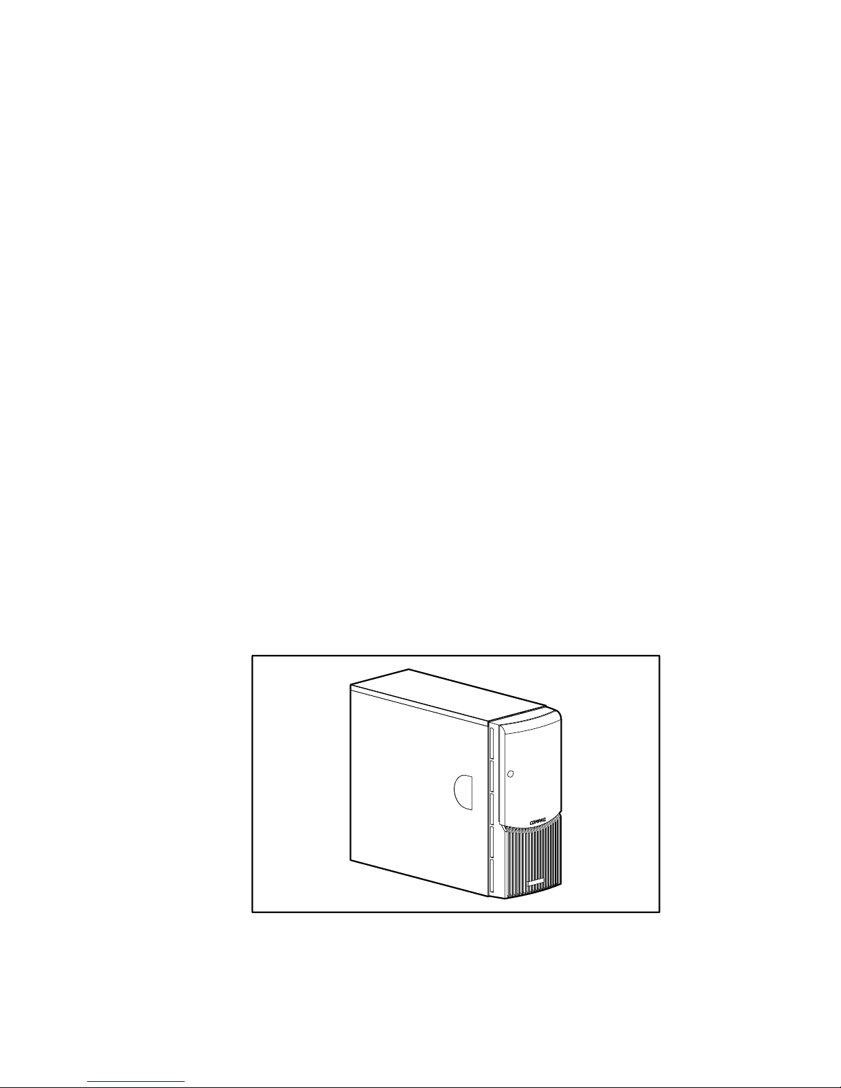
Figure 1-1. Compaq ProLiant ML330e/ML330 server
Page 15
Server Features 1-3
Standard Features
The following features are standard on the ProLiant ML330e/ML330 server,
unless otherwise noted.
Drive Bay Components
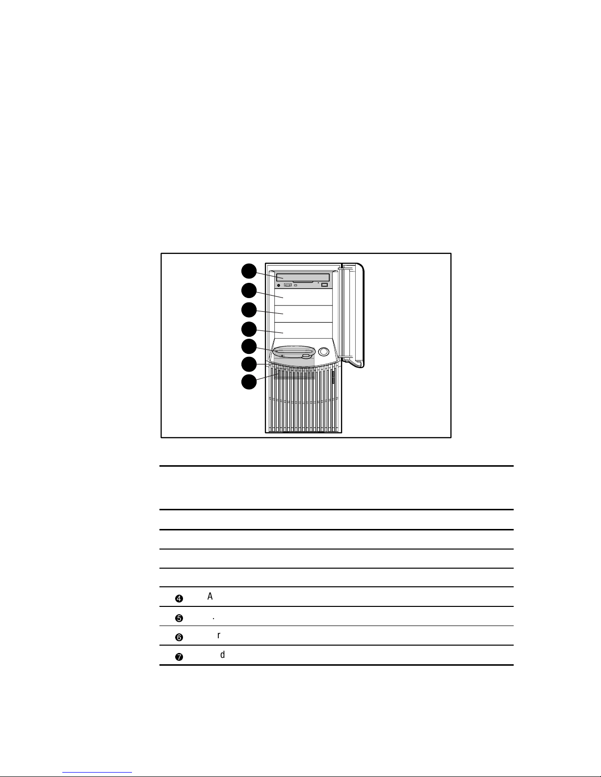
The ProLiant ML330e/ML330 server supports a maximum of seven internal
drive bays. Figure 1-2 and Table 1-1 show the drive configuration.
1
2
3
4
5
6
7
Figure 1-2. Identifying drive positions
Table 1-1
Drive Bay Components and Dimensions
Item Component Dimension
IDE CD-ROM drive bay 5.25 in x 1.60 in
Available removable media bay 5.25 in x 1.60 in
Available removable media bay 5.25 in x 1.60 in
Available removable media bay 5.25 in x 1.60 in
1.44-MB diskette drive bay 3.5 in x 1.0 in
Hard drive bay 3.5 in x 1.0 in
Hard drive bay 3.5 in x 1.0 in
Page 16
1-4 Compaq ProLiant ML330e/ML330 Server Setup and Installation Guide
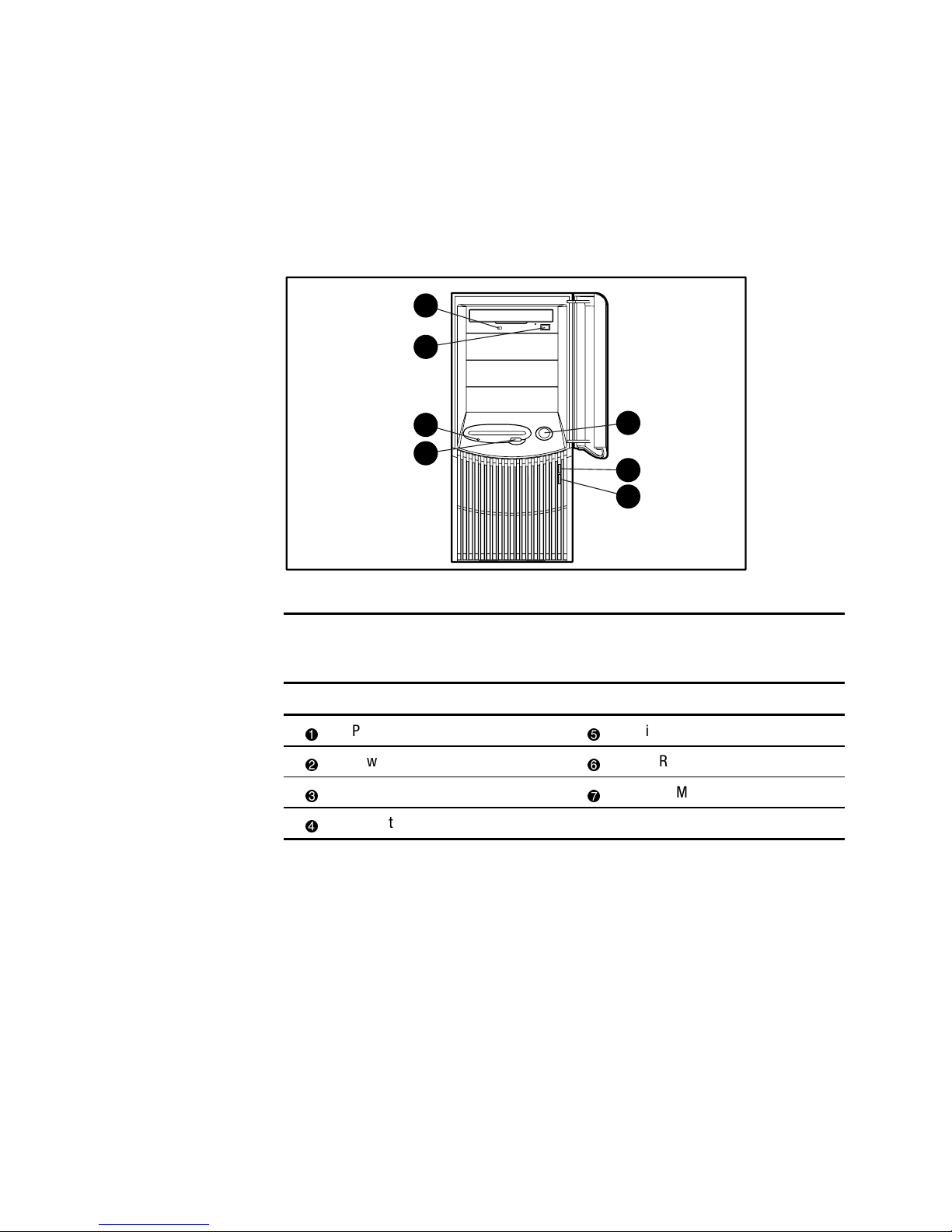
Front Panel Components
Figure 1-3 and Table 1-2 show the front panel components, including buttons
and LEDs.
7
6
5
4
3
2
1
Figure 1-3. Front panel components
Table 1-2
Front Panel Components
Item Component Item Component
Power button
Diskette drive activity LED
Power LED
CD-ROM drive eject button
Hard drive activity LED
CD-ROM drive activity LED
Diskette drive eject button
Page 17
Server Features 1-5
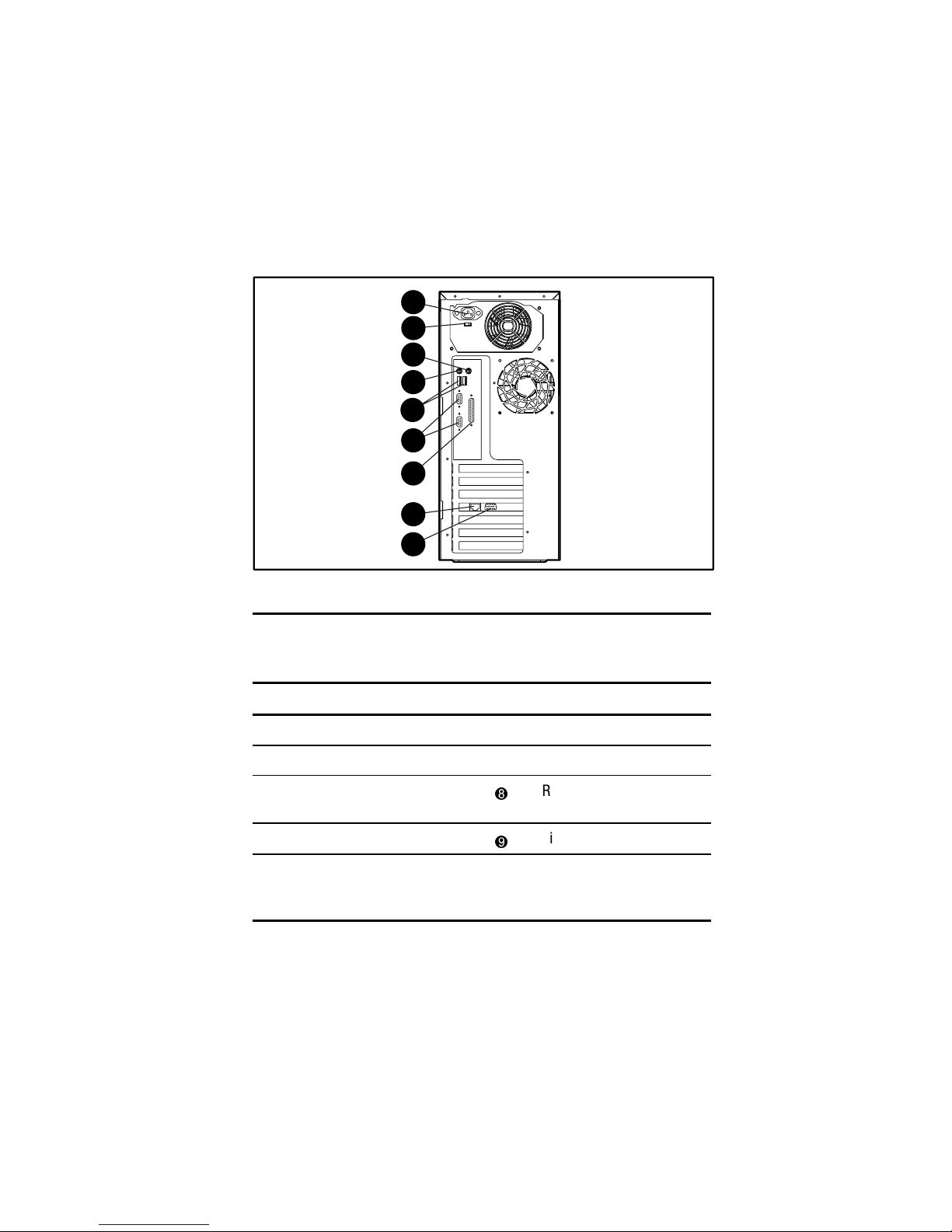
Rear Panel Connectors
Figure 1-4 and Table 1-3 show the connectors on the rear panel of the
ProLiant ML330e/ML330 server.
1
3
4
7
8
9
6
5
2
Figure 1-4. Identifying rear panel connectors
Table 1-3
Rear Panel Connectors
Item Connector Item Connector
Power cord connector
Serial port connectors
Voltage selector switch
Parallel port connector
Mouse connector
RJ-45 Ethernet for NIC
connector
Keyboard connector
Video connector
USB port connectors
(ProLiant ML330e
server only)
Page 18

1-6 Compaq ProLiant ML330e/ML330 Server Setup and Installation Guide
System Board Components
Figure 1-5 and Table 1-4 show the components and connectors of the
ProLiant ML330e/ML330 server system board.
16 17
18
22
23
20
24251
2
3
4
5
6
7
10
8
9
11
12
1415
19
21
13
Figure 1-5. Identifying system board components
Page 19
Server Features 1-7
Table 1-4
System Board Components
Item Component Item Component Item Component
32-bit PCI slot 6
Serial port
connector B
DIMM sockets (four)
32-bit PCI slot 5
Parallel port connector
Primary IDE connector
32-bit PCI slot 4
Serial port
connector A
Power button connector
32-bit PCI slot 3
(Server Feature Board)
USB port connectors
(ProLiant ML330e
server only)
Server Management
Information Cable
(SMIC) connector
64-bit PCI slot 2
Mouse connector
Secondary IDE
connector
64-bit PCI slot 1
(half-length)
Keyboard connector
Remote Insight
Lights-Out Edition board
connector
Battery
Power supply
connector
System configuration
switch (SW2)
System fan connector
Diskette drive
connector
Reserved processor
switch (SW1)
Processor
IMPORTANT: Power for the Remote Insight Lights-Out Edition board must come from the
external power supply of the Remote Insight Lights-Out Edition board and not from the
system board.
Page 20

1-8 Compaq ProLiant ML330e/ML330 Server Setup and Installation Guide
Processors and System Memory
■ Pentium III processor with integrated 256-KB Cache Single
Processor capability
■ ECC for memory error detection and correction
■ 64-MB, PC133-MHz ECC Registered SDRAM DIMM system memory,
expandable to 2 GB
■ Support for 64-MB, 128-MB, 256-MB, or 512-MB, PC133-MHz ECC
Registered SDRAM DIMMs
■ Support for up to four Registered SDRAM DIMMs (PC133-MHz ECC),
installed one at a time in any order
Expansion Slots
■ Six expansion slots (five available): four 32-bit PCI slots (three
available) and two 64-bit PCI slots
■ PCI bus that provides peripheral transactions at a bus clock speed of
33 MHz
Disk Controllers
■ Integrated single-channel Wide Ultra2 SCSI controller on the PCI local
bus (ProLiant ML330 server). The controller provides an internal SCSI
bus.
■ Integrated dual-channel ATA/100 controller (ProLiant ML330e server)
■ Optional controller boards for controller duplexing or expanding storage
capacity available
Network Controller
■ Integrated PCI 10/100 Wake on LAN NIC
■ Preboot Execution Environment (PXE) support for downloading
complete operating system configurations from your network
(ProLiant ML330e servers only)
Page 21

Server Features 1-9
Ports/Connectors
■ Serial (2)
■ Parallel
■ Keyboard
■ Mouse
■ USB (2)—Available with the ProLiant ML330e server only
BIOS
■ ROMPaq™ utility for BIOS firmware upgrade
■ BIOS Setup utility for system configuration (ProLiant ML330 server)
■ ROM Based Setup Utility (RBSU) for system configuration
(ProLiant ML330e server)
Page 22

1-10 Compaq ProLiant ML330e/ML330 Server Setup and Installation Guide
Server Feature Board Components
(ProLiant ML330 Server)
Figure 1-6 and Table 1-5 show the components of the Server Feature Board
for the ProLiant ML330 server with a standard integrated single-channel Wide
Ultra2 SCSI controller.
NOTE: For Server Feature Board components for the ProLiant ML330e server, refer to
Figure 1-7 and Table 1-6 in the following section “Server Feature Board Components
(ProLiant ML330e Server).”
5
6
7
8
9
4
3
1
2
Figure 1-6. Identifying Server Feature Board components
(ProLiant ML330 server)
Table 1-5
Server Feature Board Components (ProLiant ML330 Server)
Item Component Item Component
SCSI channel connector
Video connector
Server Management Information
Cable (SMIC) connector
Network speed indicator
Server Feature Board
configuration switch
Network link status indicator
Replaceable lithium battery
(CR2032)
Network activity indicator
RJ-45 Ethernet connector for NIC
Page 23
Server Features 1-11
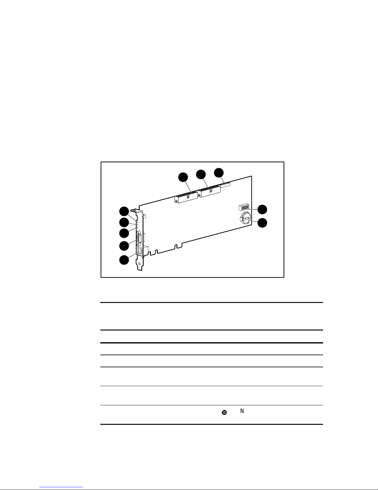
Server Feature Board Components
(ProLiant ML330e Server)
Figure 1-7 and Table 1-6 show the components of the Server Feature Board
for the ProLiant ML330e server with a standard integrated dual-channel
ATA/100 controller.
NOTE: For Server Feature Board components for the ProLiant ML330 server, refer to
Figure 1-6 and Table 1-5 in the preceding section “Server Feature Board Components
(ProLiant ML330 Server)”.
6
7
8
9
10
5
4
3
1
2
Figure 1-7. Identifying Server Feature Board components
(ProLiant ML330e server)
Table 1-6
Server Feature Board Components (ProLiant ML330e Model)
Item Component Item Component
ATA/100 connector (primary)
RJ-45 Ethernet connector for NIC
ATA/100 connector (secondary)
Video connector
Server Management Information
Cable (SMIC) connector
Network speed indicator
Server Feature Board configuration
switch
Network link status indicator
Replaceable lithium battery
(CR2032)
Network activity indicator
Page 24

1-12 Compaq ProLiant ML330e/ML330 Server Setup and Installation Guide
Interfaces
■ Integrated single-channel Wide Ultra2 SCSI controller
(ProLiant ML330 server)
■ Integrated dual-channel ATA/100 controller (ProLiant ML330e server)
■ Integrated PCI 10/100 Wake on LAN NIC
Video
■ Integrated ATI Rage XL Video controller providing maximum
resolution of 1600 x 1200 noninterlaced at 65 K colors
■ Support for SVGA, VGA, and EGA graphics resolution
■ 4-MB SDRAM video memory
Power Supply
■ CE Mark-compliant power supply
Warranty
The Compaq Three-Year Pre-Failure Warranty helps prevent unplanned
shutdowns of the system by allowing for the replacement of covered parts
before they fail. The warranty covers processors, memory, and hard drives.
Compaq Insight Manager, included with the system, must be installed for the
Compaq Pre-Failure Warranty to be in effect. Certain restrictions and
exclusions apply. Consult the Compaq Customer Support Center or refer to the
Limited Warranty Statement included with your server for details.
Page 25

Server Features 1-13
Server Configuration and Management
The ProLiant ML330e/ML330 server offers an extensive set of features and
optional tools to support effective server management and configuration,
including:
■ Configuration Utilities
■ Compaq SmartStart™ and Support Software
■ Compaq Insight Manager
■ Diagnostics tools (POST, DIAGS, ASR)
Configuration Utilities
The BIOS Setup utility (F10 setup), for the ProLiant ML330 server, and
RBSU (F9 setup), for the ProLiant ML330e server, perform a wide range of
configuration activities and utilities, including the following:
■ Viewing system information
■ Selecting the operating system
■ Configuring system devices and installed options
■ Selecting the primary boot controller
■ Managing storage options
■ Backing up and restoring saved configurations
■ ROMPaq utilities to upgrade flash BIOS
Compaq SmartStart and Support Software
SmartStart, located on the SmartStart and Support Software CD, is the
intelligent way to set up your Compaq server. SmartStart includes:
■ Driver updates
■ Assisted operating system installations
For information concerning SmartStart, refer to the Server Setup and
Management pack included in the shipping box.
Page 26

1-14 Compaq ProLiant ML330e/ML330 Server Setup and Installation Guide
Compaq Insight Manager
Compaq Insight Manager, which is loaded from the Compaq Management CD,
is an easy-to-use software utility for collecting server information. Compaq
Insight Manager performs the following functions:
■ Forwards server alerts and fault conditions
■ Monitors fault conditions and server performance
■ Controls server security and configuration
■ Remotely controls server
■ Initiates rapid recovery services
Diagnostic Tools
The software and firmware diagnostic tools available for your use include:
■ Power-On Self-Test (POST)
■ Diagnostics (DIAGS)
■ Automatic Server Recovery (ASR)
Page 27

Server Features 1-15
Security Features
Security features include:
■ Setup Password
■ Power-on Password
■ Diskette Drive Control
■ Diskette Write Control
■ Diskette Boot Override
■ CD Boot Override
■ Intruder Alert—ProLiant ML330 servers only
A hardware-associated security feature is the intruder alert. An intruder alert
message is displayed if the front bezel has been unlatched or removed. This
feature is available only on ProLiant ML330 servers. Refer to Chapter 5,
“Server Configuration and Utilities,” for information on enabling intruder
alert.
Most security features are established through the setup and configuration
utilities for the server. Refer to Chapter 5 for more information about the setup
utilities used with your server. For information concerning server security
features, refer to the SmartStart and Support Software CD included in the
shipping box.
Page 28
Chapter 2
Overview of Server Installation
The following instructions are provided as an overview for first-time
installation of your Compaq ProLiant ML330e/ML330 server. If you have any
problems, contact your Compaq authorized reseller.
WARNING: To reduce the risk of electric shock or damage to the equipment:
■ Do not disable the power cord grounding plug. The grounding plug is an
important safety feature.
■ Plug the power cord into a grounded (earthed) electrical outlet that is
easily accessible at all times.
■ Disconnect power from the server by unplugging the power cord from
either the electrical outlet or the server.
■ Do not place anything on power cords or cables. Arrange them so that no
one can accidentally step on or trip over them. Do not pull on a cord or
cable. When unplugging from the electrical outlet, grasp the cord by
the plug.
CAUTION: Electrostatic discharge can damage electronic components. Be sure
that you are properly grounded (earthed) before beginning any installation
procedure. See Appendix B, “Electrostatic Discharge,” for more information.
Page 29

2-2 Compaq ProLiant ML330e/ML330 Server Setup and Installation Guide
Selecting a Site
Make sure that the installation area that you select has the following features:
■ A sturdy, level installation site that includes dedicated and properly
grounded (earthed) circuits, air conditioning, and static electricity
protection
IMPORTANT: The ProLiant ML330e/ML330 server must be operated only when in an
upright, vertical position.
■ 7.6 cm (3.0 inches) clearance on all sides of server for proper ventilation
■ A separate electrical circuit for the server
CAUTION: Protect the server from power fluctuations and temporary
interruptions with a regulating uninterruptible power supply (UPS). This device
protects the hardware from damage caused by power surges and voltage spikes
and keeps the system in operation during a power failure.
Unpacking the Server
Unpack the server, keyboard, and cables according to the instructions and
illustrations printed on the Quick Start poster.
Page 30

Overview of Server Installation 2-3
Locating Materials
Locate the following materials that were shipped with your
ProLiant ML330e/ML330 server:
■ Keyboard
■ Mouse
■ Power cord
■ Documentation and software packs inside the shipping box
In addition to these supplied items, you may need:
■ Torx T-15 screwdriver
■ Phillips #2 screwdriver
■ Hardware options
■ Uninterruptible power supply (UPS)
■ Ethernet cable
■ Monitor
■ Application software
Page 31

2-4 Compaq ProLiant ML330e/ML330 Server Setup and Installation Guide
Connecting the Power Cord and
Peripheral Devices
After all optional internal hardware devices have been installed in the server,
connect the power cord and peripheral devices to the connectors located on the
rear panel of the server as indicated in Figure 2-1 and Table 2-1.
See Chapter 3, “Hardware Options Installation,” or see the options kits for
detailed instructions.
WARNING: To reduce the risk of electric shock or fire, do not plug
telecommunications/telephone connectors into the network interface
controller (NIC) receptacle.
1
3
4
7
8
9
6
5
2
Figure 2-1. Identifying rear panel connectors
Table 2-1
Rear Panel Connectors
Item Connector Item Connector
Power cord connector
Serial port connectors
Voltage selector switch
Parallel port connector
Mouse connector
RJ-45 Ethernet for NIC connector
Keyboard connector
Video connector
USB port connectors
(ProLiant ML330e server only)
Page 32

Overview of Server Installation 2-5
Installation Sequence
CAUTION: If your server has a factory-installed operating system (OS),
configure the server using the instructions in the following section,
“Preconfigured Operating System,” or data on the server could be lost.
Otherwise, follow the instructions in the “Operating System Purchased
Separately” section later in this chapter.
Preconfigured Operating System
If you ordered your server with the factory-installed operating system,
everything required to install your operating system is already on the server.
Refer to the steps provided in the Compaq Factory-Installed Operating System
Software User Guide.
CAUTION: Use the SmartStart and Support Software CD as recovery software
only. Starting the server from the SmartStart and Support Software CD
reconfigures the system and causes all data on the server to be lost.
To install your server:
WARNING: To reduce the risk of electric shock or damage to the equipment:
■ Do not disable the power cord grounding plug. The grounding plug is an
important safety feature.
■ Plug the power cord into a grounded (earthed) electrical outlet that is
easily accessible at all times.
■ Disconnect power from the server by unplugging the power cord from
either the electrical outlet or the server.
■ Do not place anything on power cords or cables. Arrange them so that no
one can accidentally step on or trip over them. Do not pull on a cord or
cable. When unplugging from the electrical outlet, grasp the cord by
the plug.
CAUTION: Before powering up the server, make sure that the power cord and
all cables have been properly connected. See Figure 2-1 and Table 2-1 for
information on the rear panel connectors of the ProLiant ML330e/ML330 server.
Page 33

2-6 Compaq ProLiant ML330e/ML330 Server Setup and Installation Guide
1. After the cables have been connected to the server, you are ready to
power up the ProLiant ML330e/ML330 server. To power up your
server:
a. To release the door latch, press and release the circular indentation
on the left side of the drive bay door
.
b. Swing the drive bay door open
.
c. Press the center of the power button on the front of the server
.
1
2
3
Figure 2-2. Powering up the server
2. To complete the factory-installed operating system process, follow the
screen instructions.
3. Refer to Chapter 5, “Server Configuration and Utilities,” and the
Compaq Management CD for information about installing the Compaq
Management Agents for your operating system.
4. After verifying your server configuration, back up your system
configuration. Refer to the SmartStart and Support Software CD for
further information on backing up your system configuration.
5. Install any application software.
To install additional options not preinstalled on your server, follow the steps in
Chapter 3.
Page 34

Overview of Server Installation 2-7
Operating System Purchased Separately
If you purchased your operating system separately, you must install it using
the SmartStart and Support Software CD. Refer to the Server Setup and
Management pack for instructions on using SmartStart. The first time the
server is configured, the SmartStart program automatically creates a necessary
partition on your hard drive. This partition cannot be used for any other
purpose and is not a traditional system partition.
Follow this sequence when installing your operating system for the first time:
CAUTION: Use the SmartStart and Support Software CD as recovery software
only. Starting the server from the SmartStart and Support Software CD
reconfigures the system and causes all data on the server to be lost.
CAUTION: To reduce the risk of damage to your server, complete the
installation process by following the detailed procedures provided later in this
chapter and in other sections of the setup and installation guide.
1. Review all guidelines listed from the beginning of this chapter through
step 1 of the “Preconfigured Operating System” section.
2. To select the type of operating system and set the date and time, run the
setup utility for your server:
G For ProLiant ML330e servers, run the ROM Based Setup Utility
(RBSU) by pressing the F9 key (when prompted).
G For ProLiant ML330 servers, run the BIOS Setup utility by
pressing the F10 key (when prompted).
For more information on the BIOS Setup utility or RBSU, see
Chapter 5, “Server Configuration and Utilities.”
3. Insert the SmartStart and Support Software CD into the CD-ROM drive.
Refer to “Configuring the Server” in the following section for complete
instructions on inserting the CD-ROM. For SmartStart and Support
Software CD initialization procedures, refer to the Server Setup and
Management pack shipped with your server or see Chapter 5.
4. To manage the server, install Compaq Insight Manager. For Compaq
Management CD initialization procedures, refer to the Server Setup and
Management pack shipped with your server.
Page 35

2-8 Compaq ProLiant ML330e/ML330 Server Setup and Installation Guide
5. Register your server. For server registration information, refer to the
Server Setup and Management pack shipped with the server or register
online at
http://www.compaq.com/register. You are required to provide your
name, server serial number, and operating system (OS) information.
You can also use the SmartStart Server Profile Diskette to register after
configuring your server with SmartStart. Follow the instructions on the
Compaq website, and then insert the SmartStart Server Profile Diskette
when prompted.
Page 36

Overview of Server Installation 2-9
Configuring the Server
The server setup utilities can be used to configure the server and options.
■ To initiate the BIOS Setup utility for the ProLiant ML330 server, press
the F10 key when prompted during the startup process.
■ To initiate RBSU for the ProLiant ML330e server, press the F9 key
when prompted during the startup process.
The SmartStart and Support Software CD contains ROMPaq and updated
drivers, and assists with the operating system installation. To use the
SmartStart and Support Software CD:
1. Locate the SmartStart and Support Software CD in the Server Setup and
Management pack.
2. After you power up the server, press the CD-ROM drive eject button.
3. Insert the SmartStart and Support Software CD into the CD-ROM drive
with the labeled side up. Handle the CD by its edges, not by the flat
surfaces of the disc.
Figure 2-3. Inserting the CD into the CD-ROM drive
4. When the busy indicator turns green, the SmartStart sequence begins.
Refer to the SmartStart and Support Software CD for more information.
Page 37

Chapter 3
Hardware Options Installation
This chapter provides procedures for installing, removing, and replacing
hardware options on the Compaq ProLiant ML330e/ML330 server.
CAUTION: Electrostatic discharge can damage electronic components. Be sure
that you are properly grounded before beginning any installation procedure.
NOTE: As a security measure on the ProLiant ML330 server, an intruder alert message (if
enabled) is displayed at startup if the front bezel has been unlatched. Refer to Chapter 5
“Server Configuration and Utilities” for information on enabling intruder alert.
Page 38

3-2 Compaq ProLiant ML330e/ML330 Server Setup and Installation Guide
Shutting Down the Server
Before installing or removing options, prepare your server by following these
steps:
CAUTION: Failure to follow these directions could result in damage to
equipment or loss of information.
1. Back up your server data and record configuration information.
2. Shut down the operating system, as directed in your operating system
instructions.
3. Power down the server by pressing the power button on the front of
the server.
IMPORTANT: To completely remove all power from the server, you must disconnect the
power cord. The front panel power button may not completely shut down power to the
server.
4. Remove the power cord.
WARNING: To reduce the risk of injury from electric shock or damage to the
equipment when installing an upgrade, make sure that the power to the server
is turned off. Remove all AC power cords to completely disconnect power from
the system.
5. Disconnect any other external equipment connections to the server.
Page 39

Hardware Options Installation 3-3
Removing the Front Bezel
To remove the front bezel:
CAUTION: To prevent damage to equipment or loss of information, make sure
that the server is powered down, all cables are disconnected from the back of
the server, and the power cord is disconnected from the grounded (earthed) AC
outlet before removing the front bezel.
1. Follow the steps in “Shutting Down the Server” earlier in this chapter.
2. Push up on the latch at the bottom of the front bezel
.
3. Swing the front bezel upward and slide it out and away from the
chassis
.
1
2
Figure 3-1. Removing the front bezel
To replace the front bezel, reverse steps 2 and 3.
NOTE: When replacing the front bezel, make sure that the top hinge points are properly
placed in the chassis before rotating the front bezel into its original position.
NOTE: As a security measure on the ProLiant ML330 server, an intruder alert message (if
enabled) is displayed at startup if the front bezel has been unlatched. Refer to Chapter 5
for information on enabling intruder alert.
Page 40

3-4 Compaq ProLiant ML330e/ML330 Server Setup and Installation Guide
Removing the Access Panel
To remove the access panel:
WARNING: To reduce the risk of personal injury from hot surfaces, allow the
internal system components to cool before touching them.
CAUTION: To prevent damage to equipment or loss of information, make sure
that the server is powered down, all cables are disconnected from the back of
the server, and the power cord is disconnected from the grounded (earthed) AC
outlet before removing the access panel.
CAUTION: Do not operate the server while the access panel is removed. This
panel is an integral part of the cooling system and removing the panel while the
system is running may adversely affect data integrity.
1. Remove front bezel. See “Removing the Front Bezel” earlier in this
chapter.
2. Remove the screw located on the left side of the front chassis
.
3. Slide the access panel forward, pull from the top of the access panel, and
then lift the panel from the chassis
.
1
2
Figure 3-2. Removing the access panel
NOTE: Turn the access panel over to locate the System Configuration label. This label
provides information about the system board of the ProLiant ML330e/ML330 server.
To replace the access panel, reverse steps 2 and 3.
Page 41

Hardware Options Installation 3-5
Removing the Bezel Blanks
To remove a bezel blank from the front bezel:
CAUTION: To prevent damage to equipment or loss of information, make sure
that the server is powered down, all cables are disconnected from the back of
the server, and the power cord is disconnected from the grounded (earthed) AC
outlet before removing the front bezel
1. Remove front bezel. See “Removing the Front Bezel” earlier in this
chapter.
2. On the back of the front bezel, pinch the tabs on each end of the bezel
blank toward each other
, and then push the bezel blank through the
front bezel
.
1
2
Figure 3-3. Removing a bezel blank
To replace a bezel blank, reverse steps 1 and 2.
Page 42

3-6 Compaq ProLiant ML330e/ML330 Server Setup and Installation Guide
Removing a Drive Tray
NOTE: The drive trays in the removable media bays can be used to mount internal
3.5-inch hard drives. The rails mounted inside the drive trays can be removed and used to
mount other devices in the removable media bays.
To remove a drive tray from a removable media bay:
CAUTION: To prevent damage to equipment or loss of information, make sure
that the server is powered down, all cables are disconnected from the back of
the server, and the power cord is disconnected from the grounded (earthed) AC
outlet before removing the access panel.
1. Follow the steps in “Removing the Access Panel” earlier in this chapter.
2. Remove the screws on each side of the drive tray.
3. Gently slide the drive tray out of the front of the chassis.
Figure 3-4. Removing the drive tray
To replace a drive tray, reverse steps 2 and 3.
Page 43

Hardware Options Installation 3-7
Storage Devices
This section discusses removal and replacement procedures for the storage
devices supported on the ProLiant ML330e/ML330 server.
Drive Positions
The ProLiant ML330e/ML330 server supports a maximum of seven internal
drive bays. Figure 3-5 and Table 3-1 show the drive configuration.
1
2
3
4
5
6
7
Figure 3-5. Identifying drive positions
Table 3-1
Drive Bay Dimensions
Item Drive Bay Dimension
IDE CD-ROM drive bay 5.25 in x 1.60 in
Available removable media drive bay 5.25 in x 1.60 in
Available removable media drive bay 5.25 in x 1.60 in
Available removable media drive bay 5.25 in x 1.60 in
1.44-MB diskette drive bay 3.5 in x 1.0 in
hard drive bay 3.5 in x 1.0 in
hard drive bay 3.5 in x 1.0 in
Page 44

3-8 Compaq ProLiant ML330e/ML330 Server Setup and Installation Guide
Installing a Hard Drive
To install a 3.5-inch hard drive:
CAUTION: To prevent damage to equipment or loss of information, make sure
that the server is powered down, all cables are disconnected from the back of
the server, and the power cord is disconnected from the grounded (earthed) AC
outlet before removing the front bezel.
1. Follow the steps in “Removing the Access Panel” earlier in this chapter.
2. Disconnect the power and data cables from the back of all devices in the
hard drive compartment.
3. Remove the three shipping screws
, press the tabs on each side of the
drive compartment
, and then pull the drive compartment from the
chassis
.
1
1
2
3
2
Figure 3-6. Removing the drive compartment
Page 45

Hardware Options Installation 3-9
4. Configure the device.
G For the ProLiant ML330 server, set the SCSI ID on the drive. You
must manually set the SCSI ID on each device to a unique value in
the range of 0 to 6 for each SCSI bus. Refer to the documentation
provided with the device for instructions on how to set the SCSI ID.
G For the ProLiant ML330e server, make sure that the jumper on the
drive is set to Cable Select so that the primary and secondary drives
are determined by the cable. Refer to Chapter 4 “Cabling
Guidelines” for more information.
5. If applicable, remove all terminating jumpers from third-party SCSI
devices. (Compaq SCSI cables are terminated.)
6. Slide the drive into the drive bay
, and then secure with two screws on
each side of the drive compartment
.
1
2
2
Figure 3-7. Installing a 3.5-inch hard drive
7. Slide the drive compartment back into the chassis.
Page 46

3-10 Compaq ProLiant ML330e/ML330 Server Setup and Installation Guide
8. Connect the power and data cables to the back of all devices.
Figure 3-8. Connecting the hard drive cables (ProLiant ML330 server)
Figure 3-9. Connecting the hard drive cables (ProLiant ML330e server)
9. Replace the access panel and the front bezel.
10. Restore power to the server.
NOTE: Using a non-Ultra2 drive impacts the SCSI bus performance of the ProLiant ML330
server.
Page 47

Hardware Options Installation 3-11
Removing a Hard Drive
To remove a 3.5-inch hard drive:
CAUTION: To prevent damage to equipment or loss of information, power down
the server, disconnect all cables from the back of the server, and disconnect the
power cord before removing the access panel.
1. Follow the steps in “Removing the Access Panel” earlier in this chapter.
2. Disconnect the power and data cables from the back of all devices in the
hard drive compartment.
Figure 3-10. Disconnecting the hard drive cables (ProLiant ML330 server)
Figure 3-11. Disconnecting the hard drive cables (ProLiant ML330e server)
Page 48

3-12 Compaq ProLiant ML330e/ML330 Server Setup and Installation Guide
3. Remove the three shipping screws, press the tabs on each side of the
drive compartment, and then pull the drive compartment from the
chassis as shown in Figure 3-6.
4. Remove two screws on each side of the drive to be removed
, and then
gently pull the drive out of the drive bay
as shown in Figure 3-12.
2
1
1
Figure 3-12. Removing a hard drive
5. Slide the drive compartment back into the chassis.
6. Connect the power and data cables to the back of all devices.
7. Replace the access panel and the front bezel.
8. Restore power to the server.
Page 49

Hardware Options Installation 3-13
Installing a Hard Drive into a Removable Media Bay
IMPORTANT: If you are installing a hard drive into a removable media drive bay, you
must use a drive tray. This drive tray can be found in the removable media bay. See
“Removing a Drive Tray” earlier in this chapter.
To install a hard drive using a drive tray:
CAUTION: To prevent damage to equipment or loss of information, make sure
that the server is powered down, all cables are disconnected from the back of
the server, and the power cord is disconnected from the grounded (earthed) AC
outlet before removing the access panel.
1. Follow the steps in “Removing the Access Panel” and “Removing a
Drive Tray” earlier this chapter.
2. Set the drive into the drive tray
.
3. Tighten the screws on the bottom of the drive tray to secure the drive
into the drive tray
.
2
1
Figure 3-13. Installing a hard drive into removable media bay drive tray
4. Slide the drive tray into the removable media bay, and then secure with
a screw on each side of the bezel blank.
Page 50

3-14 Compaq ProLiant ML330e/ML330 Server Setup and Installation Guide
5. Connect the data and power cables to the back of all devices.
Figure 3-14. Connecting the drive cables (ProLiant ML330 server)
Figure 3-15. Connecting the drive cables (ProLiant ML330e server)
6. Replace the access panel and the front bezel.
7. Restore power to the server.
Page 51

Hardware Options Installation 3-15
Installing a Tape Drive or Other Device into a
Removable Media Bay
IMPORTANT: The following section applies only to the ProLiant ML330 server or ProLiant
ML330e server models with a SCSI option card installed.
All ProLiant ML330e/ML330 server models ship standard with four
removable media bays. The top 5.25-inch bay is occupied with an IDE
CD-ROM drive. The remaining three 5.25-inch bays are available for
removable media devices. You can install three half-height devices, or one
full-height device and one half-height device, into these bays.
To install a 5.25-inch device:
CAUTION: To prevent damage to equipment or loss of information, make sure
that the server is powered down, all cables are disconnected from the back of
the server, and the power cord is disconnected from the grounded (earthed) AC
outlet before removing the access panel.
IMPORTANT: When installing a removable media device, remove the rails included in the
drive tray and install them on the device (replace any existing rails on the device). The
rails are secured to the drive tray with two screws on each rail.
1. Follow the steps in “Removing the Access Panel” and “Removing the
Bezel Blanks” at the beginning of this chapter.
2. Set the SCSI ID on the drive. You must manually set the SCSI ID on
each device to a unique value in the range of 0 to 6 for each SCSI bus.
Refer to the documentation provided with the device for instructions on
how to set the SCSI ID.
3. Remove all terminating jumpers from third-party SCSI devices.
(Compaq SCSI cables are terminated.)
Page 52

3-16 Compaq ProLiant ML330e/ML330 Server Setup and Installation Guide
4. Slide the device into the drive bay
, and then secure with screws on
each side of the device
as shown in Figure 3-16.
1
2
2
Figure 3-16. Installing a device into a 5.25-inch drive bay.
5. Connect the data and power cables to the back of the device, as shown
in Figure 3-14.
6. Replace the access panel and the front bezel. Restore power to
the server.
To install a tape drive:
CAUTION: To prevent damage to equipment or loss of information, make sure
that the server is powered down, all cables are disconnected from the back of
the server, and the power cord is disconnected from the grounded (earthed) AC
outlet before removing the access panel.
IMPORTANT: When installing a removable media device, remove the rails included in the
drive tray and install them on the device (replace any existing rails on the device). The
rails are secured to the drive tray with two screws on each rail.
1. Follow the steps in “Removing the Access Panel” and “Removing the
Bezel Blanks” at the beginning of this chapter.
2. Set the SCSI ID on the drive. You must manually set the SCSI ID on
each device to a unique value in the range of 0 to 6 for each SCSI bus.
Refer to the documentation provided with the device for instructions on
how to set the SCSI ID.
Page 53

Hardware Options Installation 3-17
3. Slide the drive into the drive bay, as shown in Figure 3-17.
Figure 3-17. Installing a tape drive
4. Connect the data and power cables to the back of the drive, as shown in
Figure 3-14.
5. Remove the two bezel blanks in the front bezel in front of the tape drive.
See “Removing the Bezel Blanks” earlier in this chapter.
6. Replace the access panel and the front bezel.
7. Restore power to the server.
Page 54

3-18 Compaq ProLiant ML330e/ML330 Server Setup and Installation Guide
Removing a Tape Drive or Other Device from a
Removable Media Bay
IMPORTANT: The following section applies only to the ProLiant ML330 server or ProLiant
ML330e server models with a SCSI option card.
To remove a tape drive or other device:
CAUTION: To prevent damage to equipment or loss of information, make sure
that the server is powered down, all cables are disconnected from the back of
the server, and the power cord is disconnected from the grounded (earthed) AC
outlet before removing the access panel.
1. Follow the steps in “Removing the Access Panel” at the beginning of
this chapter.
2. Disconnect the power and data cables from the back of the device.
Figure 3-18. Disconnecting the SCSI cable
Page 55

Hardware Options Installation 3-19
3. Remove the screws on each side of the device
.
4. Gently slide the device out from the front of the chassis
.
1
1
2
Figure 3-19. Removing a device from the removable media bay
5. Install another device or a drive tray. Replace the bezel blank
(or blanks). See “Removing the Bezel Blanks” and “Removing a
Drive Tray” earlier in this chapter.
6. Replace the access panel and the front bezel. Restore power to
the server.
Page 56

3-20 Compaq ProLiant ML330e/ML330 Server Setup and Installation Guide
Expansion Slots
Figure 3-20 and Table 3-2 identify the location of expansion slots.
1
2
3
4
5
6
Figure 3-20. Locating expansion slots
Table 3-2
Expansion Slots
Item Slot Type Slot Number
64-bit PCI (half-length) 1
64-bit PCI 2
32-bit PCI (Server Feature Board) 3
32-bit PCI 4
32-bit PCI 5
32-bit PCI 6
Page 57

Hardware Options Installation 3-21
Installing an Expansion Board
To install an expansion board:
CAUTION: To prevent damage to equipment or loss of information, make sure
that the server is powered down, all cables are disconnected from the back of
the server, and the power cord is disconnected from the grounded (earthed) AC
outlet before removing the access panel.
CAUTION: To prevent damage to the system when handling components, see
Appendix B, “Electrostatic Discharge.”
1. Follow the steps in “Removing the Access Panel” earlier in this chapter.
2. From inside the chassis, push the expansion slot cover through the rear
of the chassis.
Figure 3-21. Removing expansion slot cover
Page 58

3-22 Compaq ProLiant ML330e/ML330 Server Setup and Installation Guide
3. Insert the expansion board into the slot and secure with a screw on the
top of the board.
Figure 3-22. Installing an expansion board
4. Connect any cables to the expansion board.
To remove an expansion board, reverse steps 1 through 4.
Configuring PCI Devices
Interrupt sharing between PCI devices may occur in certain configurations.
The system setup utility is designed to optimally configure the system.
However, interrupt conflicts may occur between PCI devices. Refer to
Chapter 5, “Server Configuration and Utilities,” for more information on the
setup utility used by your server.
NOTE: Interrupt sharing does not present a problem for like devices, such as two network
interface controllers.
Page 59

Hardware Options Installation 3-23
Interrupt Settings
NOTE: You can reset interrupt settings at any time by running the setup utility, and
choosing “Set Defaults and Exit.”
The setup utility for your server allows you to view and change the interrupts
assigned to each device. However, you may notice that changing the interrupt
of one device changes another device interrupt. For information on the setup
utility used by your server, refer to Chapter 5, “Server Configuration and
Utilities.”
Memory Modules
Technical Information and Important Guidelines for
DIMM Installation
CAUTION: To prevent damage to equipment or loss of information, make sure
that the server is powered down, all cables are disconnected from the back of
the server, and the power cord is disconnected from the grounded (earthed) AC
outlet before removing the access panel.
CAUTION: To prevent damage to the system when handling components, see
Appendix B, “Electrostatic Discharge.”
CAUTION: When handling a memory module, be careful not to touch any of the
contacts. Doing so may damage the module.
When installing DIMMs, you must follow these guidelines:
■ Use only 64-MB, 128-MB, 256-MB, or 512-MB Registered
PC133-MHz ECC SDRAM DIMMs.
■ DIMMs must be industry-standard, 168-pin, PC133-MHz Registered
SDRAM DIMMs. The SDRAM DIMMs must support CAS Latency 3
(CL=3).
■ Do not mix ECC and non-ECC SDRAM DIMMs. If different types of
DIMMs are mixed, the system does not function properly.
Page 60

3-24 Compaq ProLiant ML330e/ML330 Server Setup and Installation Guide
Installing a Memory Module
The ProLiant ML330e/ML330 server supports PC133-MHz Registered ECC
SDRAM DIMMs. Additional DIMMs (64-MB, 128-MB, 256-MB, or
512-MB) are available to upgrade the memory. The server has four DIMM
sockets located on the system board.
It is not necessary to install DIMMs in pairs, and they can be installed into any
available socket.
4
3
2
1
Figure 3-23. Locating DIMM sockets
Table 3-3
DIMM Sockets
Item Component Item Component
DIMM socket 1
DIMM socket 3
DIMM socket 2
DIMM socket 4
Page 61

Hardware Options Installation 3-25
To install a DIMM:
1. Follow the steps in “Removing the Access Panel” at the beginning of
this chapter.
2. Press outward on both latches of the DIMM socket at the same time
.
3. Insert the DIMM into the socket
.
CAUTION: A DIMM can be installed only one way or damage will result. Be sure
to match the two key slots on the DIMM with the tab on the DIMM socket. Push
the DIMM down into the DIMM socket, ensuring that it is fully inserted and
properly seated.
4. Return latches to the upright position
.
1
1
2
3
Figure 3-24. Installing a DIMM
Page 62

3-26 Compaq ProLiant ML330e/ML330 Server Setup and Installation Guide
Removing a Memory Module
To remove a DIMM:
1. Follow the steps in “Removing the Access Panel” at the beginning of
this chapter.
2. Press outward on both latches of the DIMM socket at the same time
.
This releases the DIMM and pushes it partially out of the socket.
3. Lift the DIMM from the socket
.
1
1
2
Figure 3-25. Removing a DIMM
Page 63

Hardware Options Installation 3-27
Replacing the Battery
The ProLiant ML330e/ML330 server has nonvolatile memory, which requires
a battery to retain system information. There is a battery on the system board
and a battery on the Server Feature Board. These batteries are required to
maintain certain system data.
IMPORTANT: Refer to Regulatory Compliance Notices in Appendix A for battery disposal
information.
Replacing the System Board Battery
If your server no longer automatically displays the correct date and time, you
may need to replace the battery that provides power to the real-time clock.
When replacing a battery, use a CR2032 3-volt lithium coin cell battery.
After you have completed the battery installation, reconfigure your system by
running BIOS Setup utility (F10) for the ProLiant ML330 server or RBSU
(F9) for the ProLiant ML330e server. See Chapter 5 for more information on
these setup utilities.
WARNING: The system board contains a lithium battery. There is a risk of fire
and chemical burn if the battery is handled improperly. Do not disassemble,
crush, puncture, short external contacts, dispose of in water or fire, or expose
the battery to temperatures higher than 60°C (140°F).
To replace the lithium battery:
CAUTION: To prevent damage to equipment or loss of information, make sure
that the server is powered down, all cables are disconnected from the back of
the server, and the power cord is disconnected from the grounded (earthed) AC
outlet before removing the access panel.
CAUTION: Static electricity can damage electronic components of the server.
Before beginning these procedures, be sure that you are discharged of static
electricity by briefly touching a grounded metal object.
Page 64

3-28 Compaq ProLiant ML330e/ML330 Server Setup and Installation Guide
1. Follow the steps in “Removing the Access Panel” at the beginning of
this chapter.
2. Locate the battery on the system board. See Figure 3-26 for the location
of the battery.
NOTE: If you have expansion boards installed, it may be necessary to remove them in
order to gain access to the battery.
3. Slide the battery out of the holder
. Lift the battery away from the
holder
.
1
2
Figure 3-26. Removing the battery from the system board
4. Slide the replacement battery into the proper position with the positive
(+) side up.
IMPORTANT: Positive polarity should be positioned up.
5. Reconfigure your system by running BIOS Setup utility (F10) for the
ProLiant ML330 server or RBSU (F9) for the ProLiant ML330e server.
See Chapter 5 for more information on these setup utilities.
Page 65

Hardware Options Installation 3-29
Replacing the Server Feature Board Battery
WARNING: The Server Feature Board contains a lithium battery. There is a risk
of fire and chemical burn if the battery is handled improperly. Do not
disassemble, crush, puncture, short external contacts, dispose of in water or
fire, or expose the battery to temperatures higher than 60°C (140°F).
CAUTION: To prevent damage to equipment or loss of information, make sure
that the server is powered down, all cables are disconnected from the back of
the server, and the power cord is disconnected from the grounded (earthed) AC
outlet before removing the access panel.
CAUTION: Static electricity can damage electronic components of the server.
Before beginning these procedures, be sure that you are discharged of static
electricity by briefly touching a grounded metal object.
To install the new battery:
1. Follow the steps in “Removing the Access Panel” at the beginning of
the chapter.
2. Remove the Server Feature Board from expansion slot 3. See
“Expansion Slots” earlier in this chapter.
3. Slide the battery out of the holder, and then lift the battery away from
the holder.
4. Slide the replacement battery into the proper position with the positive
(+) side up.
Figure 3-27. Replacing the Server Feature Board battery
Page 66

3-30 Compaq ProLiant ML330e/ML330 Server Setup and Installation Guide
5. Replace the Server Feature Board in expansion slot 3.
See “Installing an Expansion Board” earlier in this chapter for detailed
instructions.
6. Replace the server access panel and connect cables to the server.
7. Reconfigure your system by running BIOS Setup utility (F10) for the
ProLiant ML330 server or RBSU (F9) for the ProLiant ML330e server.
See Chapter 5 for more information on these setup utilities.
Page 67

Chapter 4
Cabling Guidelines
Storage Device Installation Guidelines
This chapter provides an overview of the cabling that resides in the system
chassis of a Compaq ProLiant ML330e/ML330 server. This chapter also
includes information on how to cable SCSI, ATA, and removable media
devices in the system, as well as information about all critical system cabling.
SCSI Cabling (for the ProLiant ML330 Server)
Consider the following guidelines when adding SCSI devices to your
ProLiant ML330 server:
NOTE: For ProLiant ML330e server cabling information, refer to the section
“ATA/100 Cabling” later in this chapter.
■ As a general rule, a maximum of seven devices may be added per
channel. Your server is equipped with one Wide Ultra2 SCSI channel.
■ Be sure to remove all terminating jumpers from third-party
SCSI devices.
Page 68

4-2 Compaq ProLiant ML330e/ML330 Server Setup and Installation Guide
Identifying the Internal SCSI Components
Before cabling the server, note the removable media and hard drive
compartment locations as shown in Figure 4-1 and Table 4-1. For additional
information about installing optional SCSI devices, refer to the documentation
included with the SCSI devices.
2
3
1
Figure 4-1. Internal SCSI components
Table 4-1
Internal SCSI Components
Number Description
Removable media bay area
Hard drive bay area
SCSI connector
Page 69

Cabling Guidelines 4-3
The SCSI cable shown in Figure 4-2 is included with the ProLiant ML330
server.
Figure 4-2. Identifying the SCSI cable with terminator
The SCSI cable shown in this illustration supports up to five SCSI devices and
comes with a terminator on the end.
Page 70

4-4 Compaq ProLiant ML330e/ML330 Server Setup and Installation Guide
Identifying and Connecting a
Fast SCSI-2 Device (Narrow)
Some SCSI devices require a special adapter, which is not standard with your
server, to connect with the SCSI cable included with your server.
If you are installing a device that uses a Fast SCSI-2 interface, you must use a
68-to-50 pin SCSI adapter (Part Number 199618-001), shown in Figure 4-3.
This adapter should be installed between the 50-pin interface on the device and
the 68-pin SCSI cable connected to the SCSI connector on the Server
Feature Board.
Figure 4-3. 68-to-50 pin (wide-to-narrow) SCSI adapter
Page 71

Cabling Guidelines 4-5
Connecting an Integrated Wide Ultra2 SCSI
Controller to an Internal SCSI Hard Drive or
Other SCSI Device
The following steps detail the procedure for connecting cables from an
integrated Wide Ultra2 SCSI controller to an internal SCSI hard drive or other
device:
1. Follow the steps in the sections following “Installing a Hard Drive” or
“Installing a Tape Drive or Other Device into a Removable Media Bay”
in Chapter 3.
2. Make sure the SCSI ID is uniquely set for each device.
3. Locate the Wide Ultra2 SCSI cable connected to the SCSI connector.
4. Install the next available connector to the hard drive or SCSI device.
5. Install the next available power connector to the hard drive or SCSI
device.
Figure 4-4. Cabling an integrated Wide Ultra2 SCSI controller to a hard drive
or other device
Page 72

4-6 Compaq ProLiant ML330e/ML330 Server Setup and Installation Guide
Connecting Internal Hard Drives to
Smart Array Controllers
Many configurations are possible when multiple SCSI controllers are added.
This section outlines the cabling procedure for the Smart Array Controller.
Refer to the Smart Array Controller options documentation for further
information.
The following steps outline the installation procedure for the Smart Array
Controller:
1. Follow the steps in the sections following “Installing a Hard Drive” in
Chapter 3.
2. Locate the Wide Ultra2 SCSI cable connected to the Server Feature
Board SCSI connector.
3. Remove the cable from the SCSI connector.
Figure 4-5. Removing the Wide Ultra2 SCSI cable from the
Server Feature Board
Page 73

Cabling Guidelines 4-7
4. Reconnect the Wide Ultra2 SCSI cable to the Smart Array Controller.
Figure 4-6. Connecting the Wide Ultra2 SCSI cable to the
Smart Array Controller
NOTE: The SCSI connector on the Server Feature Board is self-terminating. If you choose
not to use the SCSI connector, you do not need to install a terminated cable.
Page 74

4-8 Compaq ProLiant ML330e/ML330 Server Setup and Installation Guide
ATA/100 Cabling (for the ProLiant ML330e Server)
Identifying the Internal ATA Components
Before cabling the server, note the removable media and hard drive
compartment locations as shown in Figure 4-7 and Table 4-2.
2
3
4
1
Figure 4-7. Internal ATA components
Table 4-2
Internal ATA Components
Number Description
Removable media bay area
Hard drive bay area
ATA connector (secondary)
ATA connector (primary)
Page 75

Cabling Guidelines 4-9
The ATA cable shown in Figure 4-8 is included with the ProLiant ML330e
server.
1
2
Figure 4-8. Identifying the ATA cable components
Connector for device 0
(primary drive)
Connector for device 1
(secondary drive)
Page 76

4-10 Compaq ProLiant ML330e/ML330 Server Setup and Installation Guide
Connecting an Integrated ATA/100 Controller to
an Internal ATA Hard Drive or Other Device
The following steps detail the procedure for connecting cables from an
integrated ATA/100 controller to an internal ATA hard drive or other device:
1. Follow the steps in the sections following “Installing a Hard Drive” or
“Installing a Tape Drive or Other Device into a Removable Media Bay”
in Chapter 3.
2. Make sure that the jumper on the drive is set to Cable Select.
3. Locate the ATA cable connected to the primary ATA connector on the
Server Feature Board. If both connectors 0 and 1 of the primary ATA
cable are already connected to installed devices, locate the secondary
ATA cable. The secondary ATA cable is connected to the secondary
ATA connector on the Server Feature Board.
4. Install cable connector 0 of the cable to the hard drive or ATA device. If
cable connector 0 is already connected to an installed device, use cable
connector 1.
IMPORTANT: Make sure that all devices are connected to the ATA cables in the
following order: primary cable connector 0, primary cable connector 1, secondary
cable connector 0, secondary cable connector 1.
5. Install the next available power connector to the hard drive or ATA
device.
Figure 4-9. Cabling an integrated ATA/100 controller to a hard drive or other
device
Page 77

Cabling Guidelines 4-11
Connecting the Server Management
Information Cable (SMIC)
The Server Management Information Cable (SMIC) provides system-critical
management information to the operating system. Proper SMIC connections
help avoid potential system failure and BIOS error messages. Figure 4-10 and
Figure 4-11 illustrate the proper SMIC connection between the system board
and the Server Feature Board.
Figure 4-10. Connecting the Server Management Information Cable
(ProLiant ML330 server)
Figure 4-11. Connecting the Server Management Information Cable
(ProLiant ML330e server)
Page 78

Chapter 5
Server Configuration and Utilities
This chapter provides information about the utilities and tools provided with
the Compaq ProLiant ML330e/ML330 server. The following tools and utilities
are described in this chapter:
■ BIOS Setup Utility for ProLiant ML330 Servers
■ ROM Based Setup Utility (RBSU) for ProLiant ML330e Servers
■ ROMPaq
■ SmartStart
■ Compaq Insight Manager
■ SmartStart Diskette Builder
■ Compaq Survey Utility
■ Compaq Diagnostics Utility
■ Automatic Server Recovery (ASR)
Page 79

5-2 Compaq ProLiant ML330e/ML330 Server Setup and Installation Guide
BIOS Setup Utility for
ProLiant ML330 Servers
The BIOS Setup utility performs a wide range of configuration activities
including the following:
■ Viewing system information
■ Selecting the operating system
■ Configuring system devices and installed options
■ Selecting the primary boot controller
■ Managing storage options
■ Backing up and restoring saved configurations
In addition, the BIOS Setup utility includes other features, which are outlined
in “Using the BIOS Setup Utility,” later in this chapter.
Navigating the BIOS Setup Utility
To make selections within the BIOS Setup utility, use the following keys:
■ To access the BIOS Setup utility, press F10 during powerup when
prompted in the lower right corner of the screen.
■ The Arrow keys navigate through the menu system.
■ The Tab key navigates through individual fields on the screen.
■ Selections are made by pressing the Enter key.
■ Selections are cancelled by pressing the Escape key.
■ Selections and changes are saved by pressing the F10 key
Page 80

Server Configuration and Utilities 5-3
Using the BIOS Setup Utility
NOTE: Most of the features in the BIOS Setup utility are not required in the setup of your
server. The options in this utility are designed to assist with specific server configuration
issues.
The BIOS Setup utility is separated into a series of menu selections designed
to configure specific areas of the system. The primary menus are the File,
System, Storage, and Advanced menus.
The File Menu
The File menu is used for saving and restoring configurations, and exiting the
utility. The following is a list of selections found in this menu with an
explanation of each option:
Save to Floppy creates a backup image of the current system configuration on
an unformatted 1.44-MB diskette in the diskette drive. This process is set up to
archive current configuration settings and to overwrite any data previously
saved on the diskette.
CAUTION: All data on the diskette is overwritten during this process.
Restore from Floppy reads a backup image of the current system
configuration from a 1.44-MB diskette in the diskette drive and stores the
configuration in the system. This option can be used to restore the system to an
archived configuration.
Set Defaults and Exit restores default configuration values for the system.
This option can be used if the system has been incorrectly configured.
Ignore Changes and Exit terminates the setup utility without storing any
changes that have been made during the current BIOS setup session.
Save Changes and Exit stores the current configuration selections.
Page 81

5-4 Compaq ProLiant ML330e/ML330 Server Setup and Installation Guide
The System Menu
The System menu is used for overall system configuration settings.
The following is a list of selections found in this menu with an explanation
of each option:
System Information displays the current system configuration. This
information can be used to identify current system components without the
chassis being opened. Items displayed include:
■ Product name
■ System type
■ Processor information
■ Cache size
■ System BIOS information
■ System management information, including serial number and asset
tracking information
■ Memory and memory module information
Set Time and Date allows the user to set the system time and date.
Primary Operating System allows the selection of the operating system. This
option automatically selects appropriate advanced settings for the operating
system selected and must be set before the operating system installation.
Setup Password prevents unauthorized users from running the BIOS Setup
utility.
Power-on Password prevents the system from starting unless the specified
password has been entered.
System IDs allows the user to alter management information settings. This
management information is used by the administrator for tracking the system
and includes the factory-programmed system serial number, user-assigned
asset and ownership tags, and a factory-assigned universally unique system
identifier (UUID) used by software.
Keyboard allows the user to select an international keyboard used with
the system.
Processor Serial Number enables or disables the unique processor serial
number feature of Intel Pentium III processors.
Page 82

Server Configuration and Utilities 5-5
The Storage Menu
The Storage menu is used to configure primary storage devices connected to
the system. The following is a list of selections found in this menu with an
explanation of each option:
Diskette Drives allows the selection of the type of diskette drive connected to
the diskette drive controller in the system.
Boot Order enables the user to configure the order of devices used to start an
operating system. This option can be used to prevent the system from starting
from diskette and CD and to select which device the system scans first.
Hard Drive Controller Order allows manual selection of the controller.
When the system displays the “attempting to Boot from C:” message, the
system searches the selected controller for an operating system. Whenever an
additional storage adapter is added to the system, it is recommended that you
use this selection to confirm that you are starting from the appropriate hard
drive controller.
Advanced allows the user to configure and control removable media, as well
as to control the use of the IDE controllers in the system devices. The
following is a list of selections found in this menu:
■ Removable Media allows you to select settings for removable media
devices.
■ IDE Devices allows you to observe devices connected to the primary
and secondary IDE controllers in the system.
■ IDE Drive Timing allows changes to the mechanism used for
transferring data between various IDE devices connected to the system.
■ IDE Options allows users to select whether IDE translations are
enabled.
Page 83

5-6 Compaq ProLiant ML330e/ML330 Server Setup and Installation Guide
The Advanced Menu
The Advanced menu is used to manually assign system resource assignments
and disable some devices in the system to free resources for other devices in
the system. The following is a list of selections found in this menu with an
explanation of each option:
Power-On Self-Test (POST) allows you to set Quick Boot and POST
messages. Quick Boot is a feature that speeds the POST processes after the
system has been started correctly one time. POST messages can be disabled to
cancel text displayed during the POST process.
Embedded Devices allows you to view and manually assign resources to
embedded system devices, as well as to disable some embedded devices to
free system resources. Disable and enable the primary and secondary
IDE controller.
IMPORTANT: Compaq recommends that you do not disable the embedded SCSI
controller. Doing so disables certain system management features.
PCI IRQ Configuration allows a manual interrupt request (IRQ) for a
specific PCI device. The system automatically assigns IRQ settings for all PCI
devices in the system.
Follow these guidelines when manually assigning IRQ for PCI devices in the
system:
■ If sharing is required, share interrupts between similar devices. It is
generally safe to share IRQs between PCI devices. However, for certain
operating systems, it is best to prevent dissimilar PCI devices (for
instance, a storage controller and a network controller) from sharing the
same IRQ.
■ Use all available IRQs. Sharing IRQs can cause performance
bottlenecks. To prevent these bottlenecks, assign PCI devices to unused
IRQs, following the rules already listed.
NOTE: The latest operating systems from Microsoft, Novell, and SCO bypass the use of
IRQs and use an advanced programmable interrupt controller (APIC). The APIC has been
designed to address the issues associated with limited IRQs, multiprocessor systems, and
shared interrupts. If you are using the latest operating system, you can let the system
automatically configure interrupts for all devices in the system.
Page 84

Server Configuration and Utilities 5-7
IRQ Summary displays the list of all interrupts (IRQs) in the system, as well
as the devices using the IRQs.
APIC Table allows users to manually assign the table that is generated for the
operating system. By default, this selection is automatically set based upon the
primary operating system. In the event that you have selected “Other” as the
primary operating system, this menu allows manual override.
The mapped table is a configuration that represents the legacy IRQ
assignments for all devices in the system. The full table is a configuration that
represents the broadest interrupt assignments for devices in the system,
minimizing interrupt sharing at the possible expense of compatibility with
older operating systems.
Automatic Server Recovery enables and disables the ASR feature.
Wake Support enables and disables the wake support (PME), such as
Wake on LAN.
Network Server Mode (NSM) enables and disables the ability to start the
system without a keyboard. When enabled, this option can be used to lock out
the keyboard until the power-on password is successfully entered. The default
setting for NSM is disabled.
F1 Prompt enables and disables the F1 prompt option. When enabled, the
system ROM halts the system at the F1 prompt and alerts the user of an error
condition or system configuration change. The default setting for the F1
prompt is enabled.
Intruder Alert enables and disables the intruder alert option. When enabled,
an intruder alert message is displayed if the front bezel has been unlatched or
removed. The default setting is disabled.
Page 85

5-8 Compaq ProLiant ML330e/ML330 Server Setup and Installation Guide
ROM Based Setup Utility (RBSU) for
ProLiant ML330e Servers
RBSU performs a wide range of configuration activities including the
following:
■ Configuring system devices and installed options
■ Viewing system information
■ Selecting the operating system
■ Selecting the primary boot controller
■ Managing storage options
In addition, RBSU includes other features, which are outlined in “Using the
ROM Based Setup Utility (RBSU)” later in this chapter.
Navigating the ROM Based Setup Utility (RBSU)
To make selections within RBSU, use the following keys:
■ To access RBSU, press F9 during powerup when prompted in the lower
right corner of the screen.
■ The Arrow keys navigate through the menu system.
■ Selections are made by pressing Enter.
■ Selections are cancelled by pressing the Escape key.
■ Selections and changes are saved by pressing F10.
Page 86

Server Configuration and Utilities 5-9
Using the ROM Based Setup Utility (RBSU)
NOTE: Most of the features in RBSU are not required in the setup of your server. The
options in this utility are designed to assist with specific server configuration issues.
RBSU is separated into a series of menu selections designed to configure
specific areas of the system. The primary menus are as follows:
■ System Options
■ PCI Devices
■ Boot Controller Order
■ Date and Time
■ System Passwords
■ System Identification
■ Advanced Options
■ Utility Language
System Options
The System Options menu is used for overall system configuration settings.
The following is a list of selections found in this menu with an explanation of
each option:
OS Selection allows the selection of the operating system. This option
automatically selects appropriate advanced settings for the operating system
selected and should be set before the operating system installation.
Embedded COM Port A allows the user to enable the embedded COM
Port A at the specified resource settings or disable the option.
Embedded COM Port B allows the user to enable the embedded COM
Port B at the specified resource settings or disable the option.
Embedded LPT Port allows the user to enable the embedded LPT Port at the
specified resource settings or disable the option.
Standard Boot Order allows the user to configure the order of devices used
to start an operating system. This feature is used to prevent the system from
starting from diskette and CD, and to select which device the system scans
first.
Page 87

5-10 Compaq ProLiant ML330e/ML330 Server Setup and Installation Guide
Diskette Write Control allows the user to configure the write control of the
removable media drive. It can be set to read and write or to read only.
Diskette Boot Control allows the user to have the system boot for the
removable media device.
PCI Devices
The PCI Devices menu option is used to view and assign the IRQs for all PCI
devices.
Boot Controller Order
The Boot Controller Order menu option is used to view and assign the current
controller order.
Date and Time
The Date and Time menu option is used to set the system date and time.
System Passwords
The System Passwords menu is used to set up passwords to limit access to the
system and its setup options. The following is a list of selections found in this
menu with an explanation of each option:
Setup Password allows a setup password to be set. This password is used to
keep unauthorized users from modifying the setup options.
Power-On Password allows a power-on password to be set. This password is
used to keep unauthorized users from powering up the system.
Network Server Mode (NSM) allows the user to disable or enable the ability
to start the system with a locked keyboard or without a keyboard. The
keyboard is unlocked by entering the Power-On Password.
System Identification
The System Identification menu is used to identify the system.
Asset Tag allows the user to identify the system with an Asset Tracking
Number.
Page 88

Server Configuration and Utilities 5-11
Advanced Options
The Advanced Options menu is used to configure advanced options of the
system. The following is a list of selections found in this menu with an
explanation of each option:
MPS Table Mode allows the user to change the APIC table setting. This
selection should be automatically set by OS Selection, but it allows the user to
override the automatic selection.
POST Speed Up allows the user to enable or disable the quick or slow start
process. The slow start process performs a complete memory test.
Automatic Server Recovery (ASR) allows the user to enable or disable the
Automatic Server Recovery option.
Wake Support (PME) allows the user to enable or disable Wake
Support (PME).
Floppy Controller allows the user to enable or disable the disk controller.
Primary IDE Controller allows the user to enable or disable the primary IDE
controller.
Secondary IDE Controller allows the user to enable or disable the secondary
IDE controller.
Processor Serial Number allows the user to enable or disable the ability of
applications to read the processor serial number.
Thermal Shutdown allows the user to disable or enable the ability of the
system to shut down due to a thermal caution event. The default for this option
is enabled. Compaq does not recommend disabling this feature.
Page 89

5-12 Compaq ProLiant ML330e/ML330 Server Setup and Installation Guide
Preboot Execution Environment (PXE) Options allows the user to
download operating system configurations from the network via the NIC
connector.
■ Embedded PXE Support enables or disables the user’s ability to
remote boot from the network via the NIC connector. The default for
this option is disabled.
■ User Interface enables or disables the ability to perform an unattended
network boot via the NIC connector. The default for this option is
enabled.
Set Defaults and Exit allows the user to reset the configuration settings to
their factory defaults.
Utility Language
The Utility Language is used to set the language in which RBSU is displayed.
The user has the following choices:
■ English
■ Spanish
■ German
■ French
■ Italian
■ Japanese
ROMPaq
Using Flash ROM in Compaq servers allows the firmware (BIOS) to be
upgraded with system or option ROMPaq utilities. To upgrade the BIOS,
insert a ROMPaq diskette into the diskette drive, remove power from the
system, and then power up the system again.
The ROMPaq utility then checks the system and provides a choice (if more
than one exists) of ROM revisions to which the system can be upgraded. This
procedure is the same for both system and option ROMPaq utilities.
CAUTION: Do not power down during a firmware upgrade. A loss of power
during upgrade may corrupt the firmware and prevent the system from starting.
Page 90

Server Configuration and Utilities 5-13
SmartStart
The SmartStart and Support Software CD is used to load the system software,
thereby achieving a well-integrated server and ensuring maximum
dependability and supportability. The SmartStart and Support Software CD
contains diagnostic utilities and ROMPaq tools.
NOTE: Do not use the SmartStart and Support Software CD for loading system software if
you purchased your system with a factory-installed operating system. Refer to the
Compaq Factory-Installed Operating System Software User Guide.
To install the SmartStart and Support Software CD, run F10 setup (BIOS
Setup utility) for the ProLiant ML330 server, or F9 setup (RBSU) for the
ProLiant ML330e server, and configure the primary operating system. Next,
follow these steps:
1. With your server powered up, press the disk eject button to open the
CD-ROM tray.
2. Locate the SmartStart and Support Software CD in the Server Setup and
Management pack.
3. Insert the SmartStart and Support Software CD into the CD-ROM drive,
and then restart the system.
NOTE: Handle the CD by its edges, not by the flat surfaces of the disc.
4. When the busy indicator turns green, the SmartStart installation
sequence begins.
Refer to the SmartStart documentation included with your server to
install the operating system, create updated driver diskettes, and run
upgrade utilities.
Compaq Insight Manager
Compaq Insight Manager is the Compaq application for easily managing
network devices. Compaq Insight Manager delivers intelligent monitoring and
alerting as well as visual control of your Compaq devices. Documentation for
Compaq Insight Manager is available on the Compaq Management CD in
[CD-ROM DRIVE]:\OVERVIEW.HLP.
Page 91

5-14 Compaq ProLiant ML330e/ML330 Server Setup and Installation Guide
SmartStart Diskette Builder
The SmartStart and Support Software CD contains a utility to generate support
diskettes in the event that they are needed or the software cannot be used
directly from the SmartStart and Support Software CD. Support diskettes are
“punched-out” from data stored on the SmartStart and Support Software CD.
The support includes:
■ Array Configuration Utility
■ Operating System support
■ Diagnostic utilities
■ Server utilities
■ Erase utility
■ System and Option ROMPaq diskettes
To run the Diskette Builder, use a workstation running Windows 95,
Windows 98, Windows NT, or Windows 2000. You also need several
1.44-MB diskettes. All data on the diskettes will be overwritten. Insert the
SmartStart and Support Software CD into the workstation drive. The CD
automatically runs the Diskette Builder utility; however, if the system does not
support the “auto-run” feature, use Windows Explorer to run
[CD-ROM DRIVE]:\DSKBLDR\DSKBLDR.EXE.
Compaq Survey Utility
The Compaq Survey Utility is an online information-gathering agent that runs
on servers, collecting critical hardware and software information from various
sources.
The Compaq Survey Utility outputs the information it gathers into
SURVEY.TXT. This file is located in
[Windows NT Drive]:\COMPAQ\SURVEY for Windows NT, and
SYS:SYSTEM for NetWare. If a significant change occurs between
data-gathering intervals, the previous information is marked, and
SURVEY.TXT is overwritten to reflect the latest configuration and changes.
This file allows you to keep a historical record of change events for server
hardware and software.
The Compaq Survey Utility automatically runs at startup and on specified time
intervals. You can modify the data-gathering interval by modifying the
command-line parameters.
Page 92

Server Configuration and Utilities 5-15
Installing Survey
Installing Survey with SmartStart Installation
To install the Compaq Survey Utility through the SmartStart Setup process,
refer to the SmartStart Installation poster. This method installs an operating
system and Compaq products on a server. Do not use this method to add the
Compaq Survey Utility to an existing system.
Installing Survey from Compaq Management CD
To install the Compaq Survey Utility from the Compaq Management CD on a
Windows NT server, you must be logged on to the Windows NT server with
administrator access rights. After you log in, enter the following at the
Windows NT command prompt:
[CD-ROM DRIVE]:\Survey\Win-NT\Eng\Survey -i -c
If the target server does not have a CD drive, use Diskette Builder to create
Survey Utility diskettes.
To install the Compaq Survey Utility from the Compaq Management CD on a
NetWare server, enter the following at the NetWare system prompt:
Load [CD-ROM DRIVE]:\Survey\Netware\Eng\Sinstall
Running Survey
After the Compaq Survey Utility is installed, it gathers information by default
every Wednesday at noon and at every powerup. You can change the Compaq
Survey Utility data-gathering interval using command-line parameters. You
can also force a one-time, immediate collection.
If you want the Compaq Survey Utility to perform a one-time immediate
collection on a Windows NT server, enter the following at the Windows NT
command prompt: Survey
If you want the Compaq Survey Utility to perform a one-time immediate
collection on a NetWare server, you need to unload the utility, and then reload
it. Enter the following at the NetWare system prompt: Unload Survey
At the next NetWare system prompt, enter the following: Load Survey
You can also change the Compaq Survey Utility data-gathering interval using
command-line parameters.
Page 93

5-16 Compaq ProLiant ML330e/ML330 Server Setup and Installation Guide
Compaq Diagnostics Utility
The Diagnostics Utility is accessed from diskette. A diskette can be created
from the SmartStart and Support Software CD. To run Diagnostics, insert the
Diagnostics diskette and restart the server. The server powers up from the
diskette and runs the Diagnostics Utility.
Automatic Server Recovery (ASR)
ASR is a feature in ProLiant servers that causes the system to restart in the
event of a catastrophic OS error like a blue-screen, ABEND (abnormal end),
or panic. A system failsafe timer, the ASR timer, is started when the Compaq
System Management driver, also known as the health driver, is loaded. The
timer is reset periodically during normal OS operation, but in the event of OS
failure, the timer expires and restarts the server. ASR increases server up time
by restarting the server within 10 minutes after the system stops responding.
The Compaq Insight Manager console notifies you in the event of a server
ASR. You can disable ASR from the Compaq Insight Manager console.
Page 94

Appendix A
Regulatory Compliance Notices
Regulatory Compliance Identification
Numbers
For the purpose of regulatory compliance certifications and identification, your
server is assigned a Compaq series number. The Compaq series number for the
Compaq ProLiant ML330e/ML330 servers is Series ES1014. The series
number can be found on the product label, along with the required approval
markings and information. When requesting certification information for this
product, always refer to this series number. This series number should not be
confused with the marketing name or model number for your server.
Communications Commission Notice
Part 15 of the Federal Communications Commission (FCC) Rules and
Regulations has established Radio Frequency (RF) emission limits to provide
an interference-free radio frequency spectrum. Many electronic devices,
including computers, generate RF energy incidental to their intended function
and are, therefore, covered by these rules. These rules place computers and
related peripheral devices into two classes, A and B, depending upon their
intended installation. Class A devices are those that may reasonably be
expected to be installed in a business or commercial environment. Class B
devices are those that may reasonably be expected to be installed in a
residential environment (personal computers, for example). The FCC requires
devices in both classes to bear a label indicating the interference potential of
the device as well as additional operating instructions for the user.
Page 95

A-2 Compaq ProLiant ML330e/ML330 Server Setup and Installation Guide
The rating label on the device shows which class (A or B) the equipment falls
into. Class B devices have an FCC logo or FCC ID on the label. Class A
devices do not have an FCC logo or FCC ID on the label. After the class of the
device is determined, refer to the following corresponding statement.
Class A Equipment
This equipment has been tested and found to comply with the limits for a
Class A digital device, pursuant to Part 15 of the FCC Rules. These limits are
designed to provide reasonable protection against harmful interference when
the equipment is operated in a commercial environment. This equipment
generates, uses, and can radiate radio frequency energy and, if not installed
and used in accordance with the instructions, may cause harmful interference
to radio communications. Operation of this equipment in a residential area is
likely to cause harmful interference, in which case the user is required to
correct the interference at personal expense.
Class B Equipment
This equipment has been tested and found to comply with the limits for a
Class B digital device, pursuant to Part 15 of the FCC Rules. These limits are
designed to provide reasonable protection against harmful interference in a
residential installation. This equipment generates, uses, and can radiate radio
frequency energy and, if not installed and used in accordance with the
instructions, may cause harmful interference to radio communications.
However, there is no guarantee that interference will not occur in a particular
installation. If this equipment does cause harmful interference to radio or
television reception, which can be determined by turning the equipment off
and on, the user is encouraged to try to correct the interference by one or more
of the following measures:
■ Reorient or relocate the receiving antenna.
■ Increase the separation between the equipment and receiver.
■ Connect the equipment into an outlet on a circuit different from that to
which the receiver is connected.
■ Consult the dealer or an experienced radio or television technician for
help.
Page 96

Regulatory Compliance Notices A-3
Declaration of Conformity for Products Marked
with the FCC Logo—United States Only
This device complies with Part 15 of the FCC Rules and is subject to the
following two conditions: (1) this device may not cause harmful interference,
and (2) this device must accept any interference received, including
interference that may cause undesired operation.
For questions regarding your product, contact:
Compaq Computer Corporation
P. O. Box 692000, Mail Stop 530113
Houston, Texas 77269-2000
Or
1-800-652-6672 (1-800-OK-COMPAQ). For continuous quality improvement,
calls may be recorded or monitored.
For questions regarding this FCC declaration, contact:
Compaq Computer Corporation
P. O. Box 692000, Mail Stop 510101
Houston, Texas 77269-2000
Or
281-514-3333
To identify this product, refer to the Part, Series, or Model number found on
the product.
Modifications
The FCC requires the user to be notified that any changes or modifications
made to this device that are not expressly approved by Compaq Computer
Corporation may void the user's authority to operate the equipment.
Cables
Connections to this device must be made with shielded cables with metallic
RFI/EMI connector hoods in order to maintain compliance with FCC Rules
and Regulations.
Page 97

A-4 Compaq ProLiant ML330e/ML330 Server Setup and Installation Guide
Mouse Compliance Statement
This device complies with Part 15 of the FCC Rules. Operation is subject to
the following two conditions: (1) this device may not cause harmful
interference, and (2) this device must accept any interference received,
including interference that may cause undesired operation.
Canadian Notice (Avis Canadien)
Class A Equipment
This Class A digital apparatus meets all requirements of the Canadian
Interference-Causing Equipment Regulations.
Cet appareil numérique de la classe A respecte toutes les exigences du
Règlement sur le matériel brouilleur du Canada.
Class B Equipment
This Class B digital apparatus meets all requirements of the Canadian
Interference-Causing Equipment Regulations.
Cet appareil numérique de la classe B respecte toutes les exigences du
Règlement sur le matériel brouilleur du Canada.
European Union Notice
Products with the CE Marking comply with both the EMC Directive
(89/336/EEC) and the Low-Voltage Directive (73/23/EEC) issued by the
Commission of the European Community.
Compliance with these directives implies conformity to the following
European Norms (in brackets are the equivalent international standards):
■ EN55022 (CISPR 22) - Electromagnetic Interference
■ EN55024 (IEC61000-4-2,3,4,5,6,8,11) - Electromagnetic Immunity
■ EN61000-3-2 (IEC61000-3-2) – Power Line Harmonics
■ EN61000-3-3 (IEC61000-3-3) – Power Line Flicker
■ EN60950 (IEC950) - Product Safety
Page 98

Regulatory Compliance Notices A-5
Japanese Notice
Taiwanese Notice
Page 99

A-6 Compaq ProLiant ML330e/ML330 Server Setup and Installation Guide
Battery Replacement Notice
Your server is provided with a lithium manganese dioxide battery. There is a
danger of explosion and risk of personal injury if the battery is incorrectly
replaced or mistreated. For more information about battery replacement or
proper disposal, contact your Compaq authorized reseller or authorized service
provider.
WARNING: Your server contains an internal lithium manganese dioxide battery.
There is risk of fire and burns if the battery pack is not handled properly. To
reduce the risk of personal injury:
■ Do not attempt to recharge the battery.
■ Do not expose to temperatures higher than 60°C.
■ Do not disassemble, crush, puncture, short external contacts, or dispose of
in fire or water.
■ Replace only with the Compaq spare designated for this product.
Batteries, battery packs, and accumulators should not be disposed
of together with the general household waste. To forward them to
recycling or proper disposal, use the public collection system or
return them to Compaq, your Compaq authorized service resellers o
r
authorized service providers, or their agents.
Page 100

Regulatory Compliance Notices A-7
Laser Compliance
The CD-ROM drive contains a laser diode of gallium aluminum arsenide
(GaAlAs) emitting in the wavelength range of 780
± 35 nm. All Compaq
systems equipped with a laser device comply with safety standards, including
International Electrotechnical Commission (IEC) 825. With specific regard to
the laser, the equipment complies with laser product performance standards set
by government agencies as a Class 1 laser product. The product does not emit
hazardous laser radiation.
WARNING: Use of controls or adjustments or performance of procedures other
than those specified herein or in the laser product’s installation guide may result
in hazardous radiation exposure. To reduce the risk of exposure to hazardous
radiation:
■ Do not try to open the unit enclosure. There are no user-serviceable
components inside.
■ Do not operate controls, make adjustments, or perform procedures to the
laser device other than those specified herein.
■ Allow only Compaq authorized service providers to repair the unit.
The Center for Devices and Radiological Health (CDRH) of the U.S. Food and
Drug Administration implemented regulations for laser products on
August 2, 1976. These regulations apply to laser products manufactured from
August 1, 1976. Compliance is mandatory for products marketed in the
United States.
This marking on the internal
CD-ROM drive indicates that the
product is classified as a
CLASS 1 LASER PRODUCT.
 Loading...