

Compaq DL360 - ProLiant - Photon, ProLiant DL360 Generation 2 Setup And Installation Manual
Page 1

ProLiant DL360 Generation 2 Server
Setup and Installation Guide
First Edition (October 2001)
Part Number 233832-001
Compaq Computer Corporation
Page 2

Notice
© 2001 Compaq Computer Corporation.
Compaq, the Compaq logo, Compaq Insight Manager, Deskpro, ProLiant, ROMPaq, SoftPaq,
Netelligent, and SmartStart are trademarks of Compaq Information Technologies Group, L.P.
Microsoft, MS-DOS, Windows, and Windows NT are trademarks of Microsoft Corporation in
the United States and other countries.
Intel and Pentium are trademarks of Intel Corporation in the United States and other countries.
UNIX is a trademark of The Open Group in the United States and other countries.
All other product names mentioned herein may be trademarks of their respective companies.
Compaq shall not be liable for technical or editorial errors or omissions contained herein. The
information in this document is provided “as is” without warranty of any kind and is subject to
change without notice. The warranties for Compaq products are set forth in the express limited
warranty statements accompanying such products. Nothing herein should be construed as
constituting an additional warranty.
Compaq ProLiant DL360 Generation 2 Server
Setup and Installation Guide
First Edition(October 2001)
Part Number 233832-001
Page 3

Contents
About This Guide
Text Conventions........................................................................................................ix
Symbols in Text...........................................................................................................x
Symbols on Equipment................................................................................................x
Rack Stability .............................................................................................................xi
Getting Help ...............................................................................................................xi
Compaq Technical Support .................................................................................xi
Compaq Website ................................................................................................xii
Compaq Authorized Reseller..............................................................................xii
Chapter 1
Server Features
ProLiant DL360 Generation 2 Server...................................................................... 1-1
Industry Support ...................................................................................................... 1-2
Customer Support .................................................................................................... 1-3
Standard Features..................................................................................................... 1-3
Processors......................................................................................................... 1-3
System Memory................................................................................................ 1-3
Integrated Lights-Out ....................................................................................... 1-4
Expansion Slots ................................................................................................ 1-4
SCSI Subsystem ............................................................................................... 1-4
Smart Array 5i Controller................................................................................. 1-5
Standard Network Interface Controllers........................................................... 1-5
Mass Storage Devices....................................................................................... 1-6
Standard Interfaces ........................................................................................... 1-6
Video ................................................................................................................ 1-7
ROM................................................................................................................. 1-7
Power Supply.................................................................................................... 1-7
LED Indicators ................................................................................................. 1-7
Optional Rack Deployment Solutions .............................................................. 1-8
Page 4

iv Compaq ProLiant DL360 Generation 2 Server Setup and Installation Guide
Server Features
continued
Server Configuration and Management ................................................................. 1-10
Security Features.................................................................................................... 1-11
Diagnostic Tools .................................................................................................... 1-12
Warranties and Services......................................................................................... 1-12
Three-Year, On-Site, Limited Global Warranty ............................................. 1-13
Next Business Day Response.......................................................................... 1-13
Pre-Failure Warranty ...................................................................................... 1-13
Chapter 2
Planning the Server Installation
Optimum Environment ............................................................................................ 2-2
Space and Airflow Requirements ..................................................................... 2-2
Temperature Requirements............................................................................... 2-3
Power Requirements......................................................................................... 2-3
Grounding Requirements.................................................................................. 2-4
Rack Planning Resources......................................................................................... 2-4
Rack Warnings......................................................................................................... 2-6
Server Warnings and Cautions................................................................................. 2-6
Server Shipping Contents......................................................................................... 2-7
Optional Installation Service.................................................................................... 2-8
Chapter 3
Installing Hardware Options
Hardware Option Procedures................................................................................... 3-2
Other Options........................................................................................................... 3-3
Preparing the Server................................................................................................. 3-3
Powering Down the Server ............................................................................... 3-3
Removing the Server from the Rack................................................................. 3-6
Access Panel Warnings..................................................................................... 3-8
Removing the Access Panel.............................................................................. 3-9
Installing the Access Panel ............................................................................. 3-10
Identifying System Board Components .......................................................... 3-11
Upgrading a Processor ........................................................................................... 3-13
Removing a Processor .................................................................................... 3-14
Installing a New Processor.............................................................................. 3-16
Memory.................................................................................................................. 3-19
Installing DIMMs................................................................................................... 3-20
Installing an Expansion Board ............................................................................... 3-22
Identifying the Expansion Slots...................................................................... 3-22
Removing the PCI Riser Board Assembly...................................................... 3-23
Installing an Expansion Board........................................................................ 3-25
Page 5

About This Guide v
Installing Hardware Options
continued
Removing the CD-ROM Drive...............................................................................3-31
Installing the CD-ROM Drive ................................................................................3-32
Removing the Floppy Disk Drive...........................................................................3-32
Installing a Floppy Disk Drive................................................................................3-34
Removing Hot-Plug SCSI Hard Drive Blanks........................................................3-34
Guidelines for Installing Hot-Plug Wide Ultra3 SCSI Hard Drives.......................3-35
SCSI ID Numbers for Wide Ultra3 SCSI Models ...........................................3-36
Installing External Storage Devices.................................................................3-36
Installing Hot-Plug Wide Ultra3 SCSI Hard Drives...............................................3-37
Chapter 4
Server Installation
Server Installation Guidelines.................................................................................. 4-1
Server Installation Procedures ................................................................................. 4-2
Measuring with the Template ........................................................................... 4-2
Attaching Universal Rack Rails to the Rack .................................................... 4-4
Attaching the Fixed Cable Tray........................................................................ 4-7
Inserting the Server into the Rack .................................................................... 4-8
Connecting the Power Cord and Peripheral Devices.......................................4-10
Securing the Cables in the Fixed Cable Tray..........................................................4-12
Powering Up the Server..........................................................................................4-12
Installing an Operating System........................................................................4-14
Registering A Server .......................................................................................4-15
Routine Maintenance..............................................................................................4-15
Maintenance and Service Procedures ..............................................................4-16
Extending the Server from the Rack (Sliding Rail Option).............................4-16
Chapter 5
Integrated Smart Array Controller
Features.................................................................................................................... 5-1
SCSI Port ................................................................................................................. 5-1
Array Configuration................................................................................................. 5-2
Chapter 6
Integrated Lights-Out
Introduction ............................................................................................................. 6-1
Features.................................................................................................................... 6-2
Integrated Lights-Out Security Override ................................................................. 6-5
Using the Integrated Lights-Out Security Override Jumper .................................... 6-6
Integration with Compaq Insight Manager 7........................................................... 6-7
Browser Support...................................................................................................... 6-7
Configuration and Operation ................................................................................... 6-7
Page 6

vi Compaq ProLiant DL360 Generation 2 Server Setup and Installation Guide
Chapter 7
Server Cabling
Internal Cabling ....................................................................................................... 7-1
Internal Cabling for Mass Storage Devices ......................................................7-1
External Cabling ...................................................................................................... 7-3
Connecting the Power Cord and Peripheral Devices ........................................ 7-3
Routing the Power Cord and Peripheral Device Cables ................................... 7-3
External Mass Storage Cabling (with optional SCSI/Array controller PCI
card) .................................................................................................................. 7-5
ProLiant DL360 Generation 2 Server Maximum External Storage Cabling .... 7-6
Chapter 8
Server Configuration and Utilities
ROM-Based Setup Utility........................................................................................ 8-2
Navigating RBSU ............................................................................................. 8-2
Using RBSU ..................................................................................................... 8-2
RBSU Default Settings ..................................................................................... 8-6
Redundant ROM Support......................................................................................... 8-8
Safety and Security Benefits............................................................................. 8-8
Access to Redundant ROM Settings................................................................. 8-8
ROMPaq Utility ....................................................................................................... 8-9
Remote ROM Flash Utility ...................................................................................... 8-9
ROM Legacy USB Support ..................................................................................... 8-9
Compaq SmartStart for Servers CD....................................................................... 8-10
SmartStart Diskette Builder ................................................................................... 8-10
SmartStart Scripting Toolkit .................................................................................. 8-11
Compaq Insight Manager XE ................................................................................ 8-12
Compaq Diagnostics Utility................................................................................... 8-13
Automatic Server Recovery-2................................................................................ 8-13
Chapter 9
Integrated Management Log
Viewing the Log ...................................................................................................... 9-1
Compaq Insight Manager.................................................................................. 9-2
Compaq Survey Utility ..................................................................................... 9-2
List of Events ........................................................................................................... 9-3
Page 7

About This Guide vii
Chapter 10
Troubleshooting
When the Server Will Not Start..............................................................................10-1
Minimum Hardware Configuration .................................................................10-2
Normal Power-Up Sequence ...........................................................................10-3
Diagnosis Steps ...............................................................................................10-4
Problems after Initial Boot......................................................................................10-7
Appendix A
Regulatory Compliance Notice
Regulatory Compliance Identification Numbers .....................................................A-1
Federal Communications Commission Notice ........................................................A-1
Class A Equipment...........................................................................................A-2
Class B Equipment ...........................................................................................A-2
Declaration of Conformity for Products Marked with the FCC Logo –
United States Only............................................................................................A-3
Modifications....................................................................................................A-3
Cables ...............................................................................................................A-3
Canadian Notice (Avis Canadien) ...........................................................................A-4
Class A Equipment...........................................................................................A-4
Class B Equipment ...........................................................................................A-4
European Union Notice ...........................................................................................A-4
Japanese Notice .......................................................................................................A-5
Taiwanese Notice.....................................................................................................A-5
Laser Devices ..........................................................................................................A-5
Laser Safety Warnings......................................................................................A-6
Compliance with CDRH Regulations...............................................................A-6
Compliance with International Regulations .....................................................A-6
Laser Product Label..........................................................................................A-6
Laser Information .............................................................................................A-7
Battery Replacement Notice....................................................................................A-7
Power Cords ............................................................................................................A-8
Mouse Compliance Statement .................................................................................A-8
Appendix B
Electrostatic Discharge
Preventing Electrostatic Damage.............................................................................B-1
Grounding Methods.................................................................................................B-2
Page 8

viii Compaq ProLiant DL360 Generation 2 Server Setup and Installation Guide
Appendix C
Status LED Indicators
Front Panel Status LED Indicators...........................................................................C-1
Rear Panel Status LED Indicators............................................................................C-3
Hot-Plug SCSI Hard Drive Status LED Indicators ..................................................C-5
System Board Status LED Indicators.......................................................................C-7
System LEDs and Internal Health LED Status Combinations..........................C-9
Appendix D
Switches and Jumpers
System Configuration Switches .............................................................................. D-1
Enabling ROMPaq Disaster Recovery Mode .................................................. D-4
Setting the NIC Operating Mode ............................................................................ D-4
Changing SCSI Device Jumper Settings................................................................. D-4
Appendix E
Installing a New Battery
System Board Battery Replacement.........................................................................E-1
Appendix F
Server Specifications
Operating and Performance Specifications for the ProLiant DL360 Generation
2 Server Rack Model ...............................................................................................F-1
Index
Page 9

About This Guide
This guide is designed to be used as step-by-step instructions for installation
and as a reference for operation, troubleshooting, and future upgrades.
Text Conventions
This document uses the following conventions to distinguish elements of text:
Keys Keys appear in boldface. A plus sign (+) between
two keys indicates that they should be pressed
simultaneously.
USER INPUT User input appears in a different typeface and in
uppercase.
FILENAMES File names appear in uppercase italics.
Menu Options,
Command Names,
Dialog Box Names
These elements appear in initial capital letters.
COMMANDS,
DIRECTORY NAMES,
and DRIVE NAMES
These elements appear in uppercase.
Type When you are instructed to type information, type
the information without pressing the Enter key.
Enter When you are instructed to enter information, type
the information and then press the Enter key.
Page 10

x Compaq ProLiant DL360 Generation 2 Server Setup and Installation Guide
Symbols in Text
These symbols may be found in the text of this guide. They have the following
meanings.
WARNING: Text set off in this manner indicates that failure to follow directions
in the warning could result in bodily harm or loss of life.
CAUTION: Text set off in this manner indicates that failure to follow directions
could result in damage to equipment or loss of information.
IMPORTANT: Text set off in this manner presents clarifying information or specific
instructions.
NOTE: Text set off in this manner presents commentary, sidelights, or interesting points
of information.
Symbols on Equipment
These icons may be located on equipment in areas where hazardous conditions
may exist.
Any surface or area of the equipment marked with these symbols
indicates the presence of electrical shock hazards. Enclosed area
contains no operator serviceable parts.
WARNING: To reduce the risk of injury from electrical shock hazards,
do not open this enclosure.
Any RJ-45 receptacle marked with these symbols indicates a Network
Interface Connection.
WARNING: To reduce the risk of electrical shock, fire, or damage to
the equipment, do not plug telephone or telecommunications
connectors into this receptacle.
Page 11
About This Guide xi
Any surface or area of the equipment marked with these symbols
indicates the presence of a hot surface or hot component. If this
surface is contacted, the potential for injury exists.
WARNING: To reduce the risk of injury from a hot component, allow
the surface to cool before touching.
Power Supplies or Systems marked with these symbols
indicate the equipment is supplied by multiple sources of
power.
WARNING: To reduce the risk of injury from electrical shock,
remove all power cords to completely disconnect power from
the system.
Rack Stability
WARNING: To reduce the risk of personal injury or damage to the equipment,
be sure that:
■ The leveling jacks are extended to the floor.
■ The full weight of the rack rests on the leveling jacks.
■ The stabilizing feet are attached to the rack if it is a single rack
installations.
■ The racks are coupled together in multiple rack installations.
■ A rack may become unstable if more than one component is extended for
any reason. Extend only one component at a time.
Getting Help
If you have a problem and have exhausted the information in this guide, you
can get further information and other help in the following locations.
Compaq Technical Support
You are entitled to free hardware technical telephone support for your product
for as long you own the product. A technical support specialist will help you
diagnose the problem or guide you to the next step in the warranty process.
Page 12

xii Compaq ProLiant DL360 Generation 2 Server Setup and Installation Guide
In North America, call the Compaq Technical Phone Support Center at
1-800-OK-COMPAQ
1
. This service is available 24 hours a day, 7 days a week.
Outside North America, call the nearest Compaq Technical Support Phone
Center. Telephone numbers for world wide Technical Support Centers are
listed on the Compaq website. Access the Compaq website by logging on to
the Internet at http://www.compaq.com.
Be sure to have the following information available before you call Compaq:
■ Technical support registration number (if applicable)
■ Product serial number (s)
■ Product model name(s) and numbers(s)
■ Applicable error messages
■ Add-on boards or hardware
■ Third-party hardware or software
■ Operating system type and revision level
■ Detailed, specific questions
Compaq Website
The Compaq website has information on this product as well as the latest
drivers and Flash ROM images. You can access the Compaq website by
logging on to the Internet at http://www.compaq.com.
Compaq Authorized Reseller
For the name of your nearest Compaq Authorized Reseller:
■ In the United States, call 1-800-345-1518.
■ In Canada, call 1-800-263-5868.
■ Elsewhere, see the Compaq website for locations and telephone
numbers.
1
For continuous quality improvement, calls may be recorded or monitored.
Page 13

Chapter 1
Server Features
The dual processor capable ProLiantä DL360 Generation 2 server offers
state-of-the-art performance and on-board management with high availability
and tool-free serviceability in a dense rack-mount chassis. This robust 1U
[4.45 cm (1.75 inches)] server supports rapid deployment and configuration
flexibility, making it an unbeatable computing solution for high-density server
requirements.
A generation identifier (G2), located on the front of the server, indicates the
model of the server purchased. The generation identifier is required to
accurately identify the model for service and support. Throughout the user
documentation, G2 and Generation 2 are used interchangeably.
ProLiant DL360 Generation 2 Server
The Compaq ProLiant DL360 G2 server supports the latest processor and
system architecture technology, including the following components:
■ Dual-processor capability with Intel Flip-Chip Pin Grid Array
(FC-PGA2) Pentium III processors with speeds greater than 1.13 GHz
■ Synchronous DRAM (SDRAM) error-checking and correcting (ECC)
memory, which may be upgraded to a 4 GB maximum
■ Integrated Smart Array 5i Controller to provide Ultra3 RAID capability
■ Integrated Lights Out (iLO) Management Port
■ Two 1-inch hot-plug SCSI hard drive bays.
■ Two Compaq NC7780 Gigabit server NICs.
Page 14
1-2 Compaq ProLiant DL360 Generation 2 Server Setup and Installation Guide
■
ROM-Based Setup Utility (RBSU)
■ Redundant ROM
■ 133-MHz front-side bus technology
■ Two 64-bit/3.3V/66-MHz full-length PCI expansion slots
■ Front bezel system LEDs and rear NIC activity LEDs
■ Front and rear Unit identification LED switches with software control of
LEDs
■ 24X low profile CD-ROM drive
■ 1.44 MB Diskette drive
■ Toolless serviceable chassis
■ Toolless mounting fixed rails or optional sliding rails that attach to the
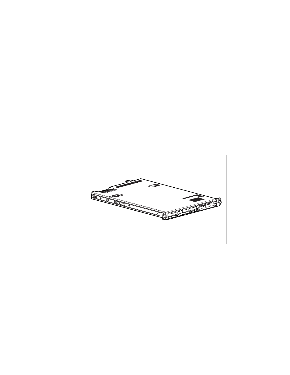
Universal rack rails. Adjustable Telco rack rails.
■ Internal modular, reduced cabling design
Figure 1-1. ProLiant DL360 G2 server
The combination of features, performance, form factor, and Compaq
manageability continue to make this platform ideal for ISP/Communications,
file and print management, Web, email, or small database applications.
Industry Support
Compaq delivers extensive testing and support for major server operating
systems. Compaq provides industry-standard buses for expansion, giving
access to thousands of high-performance PCI expansion boards, as well as
support for SCSI devices.
Page 15

Server Features 1-3
Customer Support
Compaq servers are backed by comprehensive and flexible customer support
programs. See “About This Guide” and refer to your Compaq SmartStart™ for
Servers CD for information about contacting Compaq authorized resellers or
Compaq authorized service providers in your area, or visit the Compaq
Customer Services website:
www.compaq.com/services
Standard Features
The features described in the following sections are standard on all Compaq
ProLiant DL360 G2 servers, unless otherwise specified.
Processors
ProLiant DL360 G2 servers support the following advanced processor
features:
■ 512K integrated Level 2 cache
■ Dual-processor capability with Intel Pentium III FC-PGA2 processors
■ 133-MHz front-side bus technology
■ Dual Socket 370 FC-PGA2 Pentium III processors using ServerWorks
HE-SL Chipset.
■ Support for future Intel Pentium III processors
System Memory
ProLiant DL360 G2 servers support the following memory features:
■ 133-MHz registered SDRAM memory
■ ECC memory for single-bit memory error correction and multi-bit
memory error detection
■ Interleaved dual DIMM base configuration
■ Dual DIMM upgrade
■ System memory expandable to 4 GB
Page 16

1-4 Compaq ProLiant DL360 Generation 2 Server Setup and Installation Guide
Integrated Lights-Out
The primary capabilities of Integrated Lights-Out include:
■ Dedicated LAN network connectivity through the dedicated iLO
Management Port
■ Remote control of the server regardless of the state of the server
operating system (Text only. A graphics console, with full keyboard and
mouse controls, is available as a separate option)
■ Remote cycling of server power to initiate a cold reboot
■ Server reboot from remote media (available as a separate option)
■ Virtual power button to allow remote powering up/down of server
■ Browser support for Internet Explorer
■ Integration with Compaq Insight Manager
TM
Expansion Slots
ProLiant DL360 G2 servers provide support for peripheral components. The
PCI riser board assembly has two full-length 64-bit/3.3V/66-MHz PCI
expansion slots.
SCSI Subsystem
ProLiant DL360 G2 servers include a Wide Ultra3 SCSI subsystem with the
following features:
■ One internal SCSI port supporting two internal hot-plug SCSI hard
drives
■ Maximum data transfer of 160 MB/s on SCSI bus
Page 17

Server Features 1-5
Smart Array 5i Controller
Features of the Smart Array 5i Controller include:
■ 32 MB total memory, 16 MB used for code with 16 MB for transfer
buffers and read cache
■ Support for two internal Wide Ultra3 SCSI hot-plug hard drives in
RAID 0 and RAID 1 configurations
■ Easy-to-use Array Configuration Utility
■ Option ROM Configuration for Arrays
■ Performance monitoring, Pre-Failure Notification, and Pre-Failure
Warranty through Compaq Insight Manager XE
■ Online capacity expansion
■ Support for low voltage differential SCSI devices
Standard Network Interface Controllers
The standard NICs provided with a ProLiant DL360 G2 server have the
following features:
■ Two Compaq NC7780 Gigabit server NICs
■ Auto-sensing LAN capable of 10/100/1000 Mbps
■ Full-duplex Ethernet for two-way transmission
■ PXE support
Page 18

1-6 Compaq ProLiant DL360 Generation 2 Server Setup and Installation Guide
Mass Storage Devices
The ProLiant DL360 G2 server can house two mass storage devices
(Figure 1-2). Standard configurations for drive bays include:
■ Support for two 1-inch, hot-plug SCSI hard drives
and
■ A fixed, low-profile 3.5-inch diskette drive
■ Low profile CD-ROM drive
4
1 2 3
Figure 1-2. ProLiant DL360 G2 server drive bay positions (front view)
Standard Interfaces
The server is equipped with the following standard interfaces
(see Chapter 4, Fig 4-10):
■ Serial connector (teal)
■ Video connector (blue)
■ Keyboard connector (purple)
■ Mouse connector (green)
■ Two Ethernet RJ-45 network connectors
■ Two USB ports (black)
■ Single RJ-45 Integrated Lights Out (iLO) Management Port
■ IDE interface for a CD-ROM
■ Floppy interface for a diskette drive
Page 19

Server Features 1-7
■
Remote Insight connector (30-pin) on system board for Compaq Remote
Insight Lights-Out Edition card
Video
Standard video integration in ProLiant DL360 G2 servers include:
■ Integrated ATI Rage XL 1280 × 1024,16M color video
■ Support for SVGA, VGA, and EGA graphics resolution
■ 8-MB SDRAM video memory
ROM
Compaq ROM features include:
■ Redundant ROM support
■ Software-upgradable firmware including diagnostics
■ ROMPaq™ utility used to upgrade system ROM
Power Supply
The ProLiant DL360 G2 standard power supply includes:
■ 200-W power supply
■ Auxiliary power supply output for Integrated Lights Out Management
and Compaq Remote Insight Lights-Out Edition PCI board.
LED Indicators
The ProLiant DL360 G2 server contains several sets of LEDs that indicate the
status of hardware components and settings. For a detailed explanation of
LEDs, see Appendix C, “Status LED Indicators.”
Page 20
1-8 Compaq ProLiant DL360 Generation 2 Server Setup and Installation Guide
Optional Rack Deployment Solutions
The ProLiant DL360 G2 server supports several rack deployment options.
Sliding Rail and Cable Management System
Option
The universal rack rail allows the mounting of either fixed or sliding rails. The
sliding rail and cable management system option allows the ProLiant DL360
G2 server to be mounted on sliding rails that support in-rack serviceability.
Rack depths of 24 in (61 cm) to 36 in (91 cm) are supported. The cable
management system provides a clean, effective way to route server cables.
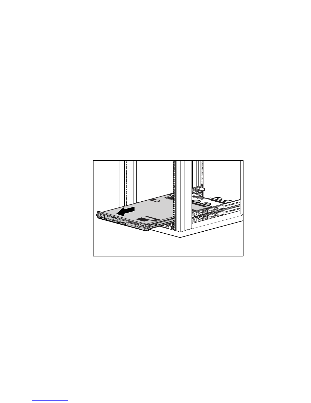
The following figure shows the server extending from the rack on optional
sliding rails.
Figure 1-3. Extending the server on sliding rails
Page 21
Server Features 1-9
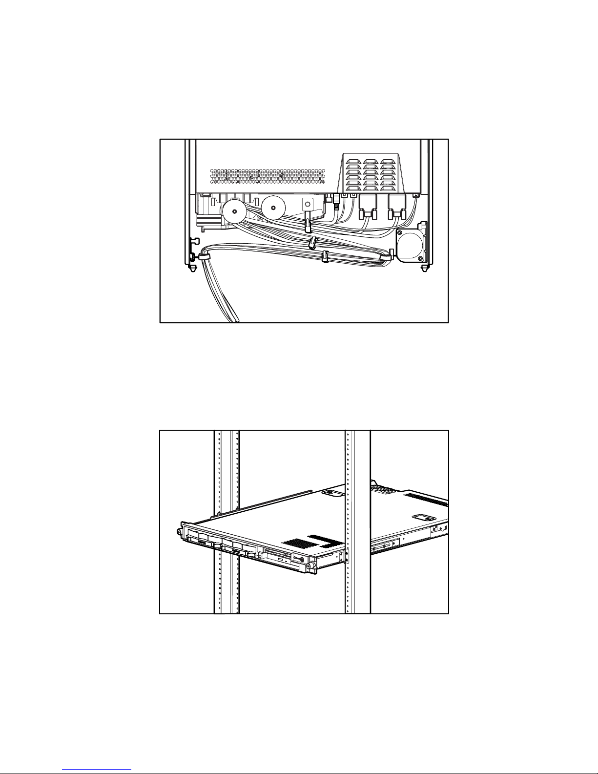
The cable management system channels the server cables along the back of the
server and to connection points on the rack.
Figure 1-4. Cables routed at the rear of the server
Telco Rack Option
The Telco option contains a set of variable-depth rack brackets that support
installation of the ProLiant DL360 G2 server into Telco racks of rail thickness
from 3 to 5 inches (7.62 to 12.7cm). These brackets adjust to fit several types
of Telco racks, and the kit contains mounting screws.
Figure 1-5. Server mounted in Telco rack
Page 22

1-10 Compaq ProLiant DL360 Generation 2 Server Setup and Installation Guide
Server Configuration and Management
Compaq offers an extensive set of features and optional tools to support server
configuration and management. This section briefly explains the following
features:
■ ROM-Based Setup Utility (RBSU)
RBSU performs a wide range of configuration activities and provides
access to numerous settings, including those for system devices,
operating system selection and boot controller order.
■ Redundant ROM Support
The ProLiant DL360 G2 server has a 2-MB ROM that acts as separate,
1-MB ROMs one of which contains the current version of the ROM
firmware, while the second contains the previous version of the
firmware. If the first ROM becomes corrupt, the system defaults to the
backup version, maximizing uptime and server availability.
■ ROMPaq Utility
Flash ROM enables you to upgrade the firmware (BIOS) with system or
option ROMPaq utilities.
■ Remote ROM Flash Utility
The Remote ROM Flash Utility enables a user with administrator
privileges to flash ROM remotely on servers running Novell NetWare or
Microsoft Windows NT and Windows 2000 operating systems.
■ ROM Legacy USB Support
The ProLiant DL360 G2 server supports several USB devices for
operating systems that provide USB support of: CD-ROM, diskette
drive, keyboard, and mouse. For operating systems without USB
support, the ProLiant DL360 G2 server ROM provides USB support for
keyboards and mouse devices.
■ Compaq SmartStart for Servers CD
The SmartStart CD is the recommended method for loading system
software, thereby achieving a well-integrated server, ensuring maximum
dependability and supportability.
■ SmartStart Diskette Builder
The SmartStart Diskette Builder is a utility that uses data stored on the
SmartStart CD to create support diskettes. Support diskettes may be
created for specific configuration needs or for software that cannot be
used directly from the SmartStart CD.
Page 23

Server Features 1-11
■
SmartStart Scripting Toolkit
The SmartStart Scripting Toolkit is a set of DOS-based utilities that
allow configuration and deployment of servers in a customized,
predictable, and unattended manner. These utilities provide scripted
server and array replication for mass server deployment and duplication
of a configured source server onto target systems with minimum user
interaction.
■ Compaq Insight Manager XE
Compaq Insight Manager XE is installed from the Compaq
Management CD and is an easy-to-use software utility for collecting
information on server performance. Data, including fault conditions,
security alerts, remote management, and recovery services are recorded.
■ Compaq Diagnostics Utility
The Diagnostics utility displays information about the server hardware
and tests the system to ensure it is operating correctly.
■ Automatic Server Recovery (ASR-2)
ASR-2 enables the server to boot automatically from either the
operating system or the Compaq utilities. If there is a critical system
failure, ASR-2 automatically restarts the server and pages a designated
system administrator.
■ Integrated Management Log (IML)
The IML provides a detailed log of key system events. This log, which
also monitors the server health log, is accessible by utilities, including
Compaq Insight Manager XE and Integrated Lights-Out (iLO)
Management.
For more detailed information about these tools and utilities, see Chapter 8,
“Server Configuration and Utilities” or refer to the SmartStart documentation,
the Server Setup and Management Pack, and the Documentation CD shipped
with your server.
Security Features
Security features for the ProLiant DL360 G2 server include:
■ Power-on password
■ Administrator password
■ Network server mode
Page 24

1-12 Compaq ProLiant DL360 Generation 2 Server Setup and Installation Guide
■
QuickLock
■ Diskette drive control
■ Diskette write control
■ Diskette boot override
■ Serial interface control
■ Configuration lock
■ NVRAM write protect
Standard security features are configured through the Compaq RBSU. To
access these settings, see Chapter 8, “Server Configuration and Utilities.”
For additional information about server security features, refer to the
Documentation CD and the SmartStart CD shipped with the server.
Diagnostic Tools
Software and firmware diagnostics tools available for use with the
ProLiant DL360 G2 include:
■ Power-On Self-Test
■ Diagnostics
■ Compaq ROMPaq utilities to upgrade flash ROM
■ Automatic Server Recovery-2
For information concerning Compaq diagnostic tools, refer to the
Documentation CD shipped with the server.
Warranties and Services
The ProLiant DL360 G2 server has the following standard services and
warranties:
■ Three-Year, On-Site, Limited Global Warranty
■ Next Business Day Response
■ Pre-Failure Warranty
Page 25

Server Features 1-13
Three-Year, On-Site, Limited Global Warranty
Compaq covers the cost of necessary parts and labor for on-site service during
the specified warranty periods. Under the global warranty, product warranty
terms at the time of purchase are honored in any country where Compaq has a
service presence. This applies to customers who may purchase a product in
one country, then transfer it to another.
IMPORTANT: Customers moving Compaq products between certain countries or regions
are asked to provide information needed to ensure that Compaq is prepared to provide the
required level of warranty service in the destination country. For information on the
Compaq Global Warranty Notification Process, contact your Compaq sales representative
or Compaq authorized reseller, or contact Compaq directly:
www.compaq.com/support
Next Business Day Response
Response time is based on commercially reasonable best efforts. In most
cases, Next Business Day response is available. In some regions and under
certain supplier restraints, Next Business Day response is not always possible.
In many areas, response uplifts are available for a fee. Contact your local
Compaq service organization for response time and availability in your area.
Pre-Failure Warranty
The ProLiant DL360 G2 server includes a Pre-Failure Warranty for
processors, hard drives, and memory purchased from Compaq through
Compaq authorized resellers. Under the terms of this warranty, supported
components are eligible for replacement before they actually fail provided that
you use Compaq Insight Manager XE and that the system determines that the
supported components have degraded below predetermined reliability
thresholds within the product warranty period.
Page 26

Chapter 2
Planning the Server Installation
This chapter provides information and instructions for planning the installation
of a new Compaq server. Figure 2-1 illustrates multiple ProLiant DL360 G2
servers installed in a rack.
Figure 2-1. ProLiant DL360 G2 servers installed in a rack
The following sections describe the server and site preparation requirements
needed for the safe and correct installation of a server. This preparation
includes:
■ Optimum environment considerations
■ Rack planning resources
■ Rack warnings
Page 27

2-2 Compaq ProLiant DL360 Generation 2 Server Setup and Installation Guide
■
Server warnings and cautions
■ Server shipping contents
■ Optional installation service
If multiple ProLiant DL360 G2 servers are to be deployed in a single rack,
consult the multiple server deployment white papers on the Compaq website:
www.compaq.com/products/servers/ProLiantdl360
Optimum Environment
When installing a Compaq ProLiant DL360 G2 server in a rack, select a
location that meets the environmental standards described in the following
paragraphs.
Space and Airflow Requirements
To allow for servicing and adequate airflow, observe the following spatial
requirements when deciding where to install a Compaq, Telco, or third-party
rack:
■ Leave a minimum clearance of 63.5 cm (25 inches) in front of the rack.
■ Leave a minimum clearance of 76.2 cm (30 inches) in the back of the
rack.
■ Leave a minimum clearance of 121.9 cm (48 inches) from the back of
the rack to the rear of another rack or row of racks.
Compaq servers draw in cool air through the rack front door and expel warm
air through the rack rear door. Therefore, the front and rear rack doors must be
adequately ventilated to allow ambient room air to enter the cabinet and warm
air to escape from the rear of the cabinet.
IMPORTANT: Do not block the ventilation openings.
When there is any vertical space in the rack not filled by servers or rack
components, the gaps between the components cause changes in airflow
through the rack and across the servers. Cover all gaps with blanking panels to
maintain proper airflow.
Compaq 9000 Series racks provide proper server cooling from flow-through
perforations in the front and rear doors that provide 64 percent open area for
ventilation.
Page 28
Planning the Server Installation 2-3
CAUTION: When using a Compaq 7000 Series rack, you must install the high
airflow rack door insert [P/N 327281-B21 (42U) and P/N 157847-B21 (22U)] to
provide proper front-to-back airflow and cooling.
CAUTION: If a third-party rack is used, observe the following additional
requirements to ensure adequate airflow and to prevent damage to the
equipment:
■ Front and rear doors: if your 42U server rack includes closing front and
rear doors, you must allow 5,350 sq cm (830 square inches) of holes
evenly distributed from top to bottom to permit adequate airflow
(equivalent to the required 64 percent open area for ventilation).
■ Side: The clearance between the installed rack component and the side
panels of the rack must be a minimum of 7 cm (2.75 inches).
CAUTION: Always use blanking panels to fill empty vertical spaces in the rack.
This arrangement ensures proper airflow. Using a rack without blanking panels
results in improper cooling that can lead to thermal damage.
Temperature Requirements
To ensure continued safe and reliable equipment operation, install or locate the
system in a well-ventilated, climate-controlled environment.
The Compaq maximum recommended ambient operating temperature
(TMRA) for most server products is 35°C (95°F). The temperature in the room
where the rack is located must not exceed 35°C
(95°F).
Power Requirements
WARNING: To reduce the risk of personal injury, fire, or damage to the
equipment, do not overload the AC supply branch circuit that provides power to
the rack. Consult the electrical authority having jurisdiction over your facility’s
wiring and installation requirements.
The installation of this equipment shall be in accordance with local/regional
electrical regulations governing the installation of information technology
equipment by licensed electricians. This equipment is designed to operate in
installations covered by NFPA 70, 1999 Edition (National Electric Code) and
NFPA 75, 1992 Edition (code for Protection of Electronic Computer/Data
Processing Equipment). For electrical power ratings on options, refer to the
product’s rating label or the user documentation supplied with that option.
Page 29

2-4 Compaq ProLiant DL360 Generation 2 Server Setup and Installation Guide
When installing more than one server, additional power distribution devices
may be required to safely provide power to all devices. Observe the following
guidelines:
■ The power load must be balanced between available AC supply branch
circuits.
■ The overall system AC current load must not exceed 80 percent of the
branch circuit AC current rating.
Grounding Requirements
For proper operation and safety, the server must be properly grounded. In the
United States, you must install the equipment in accordance with NFPA 70,
1999 Edition (National Electric Code) Article 250 as well as any local and
regional building codes. In Canada, the equipment must be installed in
accordance with Canadian Standards Association, CSA C22.1, Canadian
Electrical Code. In all other countries, the installation must follow any
regional or national electrical wiring codes, such as the International
Electrotechnical Commission (IEC) 364, parts 1 through 7. Furthermore, you
must ensure that all power distribution devices used in the installation—such
as branch wiring and receptacles—are listed or certified grounding-type
devices.
Because of the high ground leakage currents associated with multiple servers
connected to the same power source, Compaq recommends the use of a power
distribution unit (PDU) that is either permanently wired to the building’s
branch circuit or includes a non-detachable cord that is wired to an
industrial-style plug. NEMA locking-style plugs or those complying with
IEC 60309 are considered suitable for this purpose. Compaq does not
recommend using common power outlet strips for this equipment.
Rack Planning Resources
The following resource information is available on rack designs and products.
The Rack Builder Pro Configuration Tool and Rack Products documentation
information can be found on the Compaq website:
www.compaq.com/support/files/storage/index.html
The entire Rack Resource CD Kit ships with all Compaq racks. A summary of
the content of each CD follows:
■ Rack Builder Pro Configuration Tool
Page 30

Planning the Server Installation 2-5
This information aids in simulating possible configurations in a Compaq
rack. Rack Builder Pro provides the following information:
G Graphical preview of properly configured racks
G Site planning data, including power requirements, cooling mandates,
and physical specifications
G Ordering information, including required components, part numbers,
and appropriate quantities
■ Installing Rack Products video
This video provides a visual overview of operations required for
configuring a Compaq rack with rack-mountable components. It also
provides the following important configuration steps:
G Site planning
G Installing rack servers and rack options
G Cabling
G Coupling racks
■ Rack Products Documentation CD
The information on this CD allows viewing, searching, and printing of
documentation for Compaq racks and rack options. It also helps set up
and optimize new Compaq racks in a manner suitable for the server
environment.
Page 31

2-6 Compaq ProLiant DL360 Generation 2 Server Setup and Installation Guide
Rack Warnings
Before installing a rack, ensure you read and understand the following
warnings:
WARNING: To reduce the risk of personal injury or equipment damage, always
ensure that the rack is adequately stabilized before extending a component out
of the rack. Extend only one component at a time. A rack may become unstable
if more than one component is extended for any reason.
WARNING: To reduce the risk of personal injury or equipment damage, ensure
that:
■ The leveling jacks are extended to the floor.
■ The full weight of the rack rests on the leveling jacks.
■ The stabilizers are attached to the rack for single-rack installation.
■ The racks are coupled together in multiple-rack installations.
WARNING: When installing the server in a Telco rack, ensure that the rack
frame is adequately secured to the top and bottom of the building structure.
WARNING: To reduce the risk of personal injury or equipment damage, at least
two people are needed to safely unload the rack from the pallet. An empty 42U
rack can weigh as much as 115 kg (253 lb), can stand more than 2.1 m (7 ft)
tall, and may become unstable when being moved on its casters.
Never stand in front of the rack when it is rolling down the ramp from the pallet;
always handle the rack from both sides.
CAUTION: Always begin by mounting the heaviest item on the bottom of the
rack. Continue to populate the rack from the bottom to the top.
Server Warnings and Cautions
Before installing your server, ensure you understand the following warnings
and cautions:
WARNING: To reduce the risk of personal injury from hot surfaces, allow the
drives and the internal system components to cool before touching them.
Page 32

Planning the Server Installation 2-7
WARNING: To reduce the risk of electric shock or damage to the equipment:
■ Do not disable the power cord grounding plug. The grounding plug is an
important safety feature.
■ Plug the power cord into a grounded (earthed) electrical outlet that is
easily accessible at all times.
■ Unplug the power cord from the power supply to disconnect power to the
equipment.
CAUTION: Protect the server from power fluctuations and temporary
interruptions with a regulating uninterruptible power supply (UPS). This device
protects the hardware from damage caused by power surges and voltage spikes
and keeps the system in operation during a power failure.
CAUTION: Do not operate the server for long periods without the access panel.
Operating the server without the access panel results in improper airflow and
improper cooling that can lead to thermal damage.
Server Shipping Contents
Unpack the server shipping carton and locate the materials and documentation
necessary for installing a server. All of the rack-mounting hardware necessary
for installing the ProLiant DL360 G2 server into the rack is included with the
server.
The contents of the server shipping carton include the following:
■ Compaq ProLiant DL360 G2 server
■ Hardware documentation, reference information, and software products
■ Power cord
■ Rack-mounting hardware (Figure 2-2 and Table 2-1)
Page 33

2-8 Compaq ProLiant DL360 Generation 2 Server Setup and Installation Guide
3
4
2
5
1
Figure 2-2. Rack-mounting hardware
Table 2-1
Rack-Mounting Hardware
Item Description
Universal rack rail assembly with fixed rail insert
Server fixed rails (Factory mounted on server)
Measuring template
Velcro strap
Fixed cable tray
In addition to these supplied items, you may need the following items:
■ Application software diskettes
■ Options to be installed
Optional Installation Service
Compaq will install server systems. The installation service can be purchased
as a CarePaq™ packaged service or as a customized service agreement to
meet specific requirements. Some of the CarePaq services are as follows:
■ CarePaq Installation Services for Hardware
■ CarePaq Hardware and Operating System Installation for ProLiant
DL360 G2 Servers
Page 34

Planning the Server Installation 2-9
■
CarePaq Installation and Start-up Services for Microsoft Windows 2000
and Windows NT operating systems
■ CarePaq Installation and Start-up and Migration Services for Novell
NetWare operating system
■ CarePaq Installation and Start-up Services for Compaq Insight Manager
Visit the Compaq website for detailed descriptions of these CarePaq services.
This method helps ensure top performance right from the start and is
especially valuable for business-critical environments.
This optional hardware installation service is available in all countries where
Compaq has a direct or indirect service presence. Service may be ordered from
and directly provided by a Compaq authorized service reseller or, in the
United Sates only, service may be ordered by calling 1-800-OK-COMPAQ. In
the United States, Compaq makes all of the arrangements to have the system
installed by qualified guaranteed service providers. For U.S. ordering
information, refer to the Compaq services website:
www.compaq.com/services/carepaq/us/install
For worldwide ordering information, refer to the Compaq services website:
www.compaq.com/services/carepaq/install
Page 35

Chapter 3
Installing Hardware Options
If there are no options to be installed in the server, proceed to Chapter 4,
“Server Installation”.
This chapter provides information and procedures for installing hardware
options on Compaq ProLiant DL360 G2 servers. For complete instructions,
refer to the installation documentation shipped with each option kit. Refer to
the following items for an illustrated guide to installing Compaq options:
■ Hardware installation and configuration poster shipped with the server
■ Labels attached to the inside of the system unit access panel
To streamline the installation process, read the installation instructions for all
of the hardware options and identify similar steps prior to installing the
hardware options.
After all hardware options have been installed, proceed with the server
installation procedures in Chapter 4, “Server Installation.”
If any problems are encountered during installation, contact your Compaq
authorized reseller.
WARNINGS: To reduce the risk of personal injury or damage to the equipment:
■ Heed all warnings and cautions throughout the installation instructions.
■ Allow internal system components to cool before touching any surfaces.
■ Ensure that the power to the server is turned off and that the AC power
cord is disconnected before removing the access panel.
Page 36

3-2 Compaq ProLiant DL360 Generation 2 Server Setup and Installation Guide
CAUTION: Always ensure that equipment is properly grounded before beginning
any installation procedure. Electrostatic discharge resulting from improper
grounding can damage electronic components. For more information, refer to
Appendix B, “Electrostatic Discharge.”
Hardware Option Procedures
This chapter includes step-by-step instructions for the following items:
■ Preparing the server
G Powering down the server
G Removing the server from the rack
G Removing the access panel
G Installing the access panel
G Identifying system board components
■ Upgrading a processor
G Removing a processor
G Installing a new processor and PPM
■ Installing DIMMs
■ Installing an expansion board
G Identifying expansion slots
G Removing the PCI riser board assembly
G Installing an expansion board
■ Removing the CD-ROM drive
■ Installing the CD-ROM drive
■ Removing a floppy disk drive
■ Installing a floppy disk drive
■ Removing hot-plug SCSI hard drive blanks
■ Installing hot-plug Wide Ultra3 SCSI hard drives
Page 37

Installing Hardware Options 3-3
Other Options
The ProLiant DL360 G2 server supports several rack-mounting options. For
more information, see “Optional Rack Deployment Solutions” in Chapter 1,
“Server Features.”
For more information about these options, contact your Compaq authorized
reseller.
Preparing the Server
To prepare the server for installation of hardware options:
■ Power down the server (for servers previously installed and/or
operating)
■ Remove the server from the rack (for servers previously installed and/or
operating)
■ Remove the access panel
■ Identify the system board components
Powering Down the Server
To install most hardware options, all power must be removed from the system.
To power down the server before installing the hardware options:
1. Prior to installing hardware options, back up the server data.
2. Shut down the operating system as directed by the operating system
instructions.
Page 38

3-4 Compaq ProLiant DL360 Generation 2 Server Setup and Installation Guide
3. Press the front Unit Identification (UID) switch on the server . An LED
illuminates within the front and rear UID switches.
1
2
Figure 3-1. Activating the Front Unit Identification switch on the front panel
and setting the Power On/Standby switch to the standby power mode
4. Press the server Power On/Standby switch to place it in standby mode .
The Power LED within the Power On/Standby switch turns to amber
when the server activates standby power mode.
WARNING: The system power in the ProLiant DL360 G2 server is not
completely shut off by pressing the front panel Power On/Standby switch.
Placing the server Power On/Standby switch in the standby position removes
power from most areas of the server; this process may take 30 seconds.
Portions of the power supply and some internal circuitry remain active until AC
power is removed.
Page 39

Installing Hardware Options 3-5
5. At the rear of the rack locate the server being powered down by
identifying the illuminated rear Unit Identification LED switch.
Figure 3-2. Locating the Rear Unit Identification LED switch on the rear panel
6. Disconnect the power cord from the server.
The system is now without power and ready to be removed from the rack for
the installation of hardware options.
Page 40

3-6 Compaq ProLiant DL360 Generation 2 Server Setup and Installation Guide
Removing the Server from the Rack
1. Disconnect all the cables from the server rear panel (including cables
extending from expansion boards), moving from left to right
.
1
Figure 3-3. Disconnecting cables from the server rear panel
2. Fully loosen the thumbscrew that secures the fixed cable tray to the
server.
Figure 3-4. Loosening the thumbscrew that secures the fixed cable tray to the
server (cables removed for clarity)
3. Move to the front of the rack.
4. Loosen the front panel thumbscrews.
Page 41

Installing Hardware Options 3-7
5. Grasp the front panel thumbscrews and extend the server from the rack
until the rail-release latches engage. The cables will remain wrapped in
the fixed cable tray.
6. Press in and hold the rail-release latches
.
2
1
1
1
Figure 3-5. Disengaging the rail-release latches
WARNING: Avoid personal injury when pressing the rail-release latches and
sliding the server into or out of the rack. The rail-release latches can pinch your
fingertips.
7. Holding the rail-release latches, extend the server until the latches clear
the front of the rack.
8. Pull the server completely out of the rack
, and set it on a flat, level
surface.
Page 42

3-8 Compaq ProLiant DL360 Generation 2 Server Setup and Installation Guide
Access Panel Warnings
To access the system board, processors, memory sockets, expansion slots, and
other internal components, the access panel must be removed. Observe the
following warnings and cautions.
WARNING: The system power in the ProLiant DL360 G2 server is not completely
shut off by pressing the front panel Power On/Standby switch. Moving the server
Power On/Standby switch to the standby position removes power from most
areas of the server; this process may take 30 seconds. Portions of the power
supply and some internal circuitry remain active until AC power is removed.
WARNING: To reduce the risk of personal injury from hot surfaces, allow the
internal system components to cool before touching them.
CAUTION: Do not operate the server without the access panel installed because
it is required for proper airflow. Operating the server without its access panel
results in improper cooling that can lead to thermal damage.
CAUTION: Before removing the server access panel, be sure that the server is
in standby mode and that the power cord is disconnected from the server or the
electrical outlet.
CAUTION: To avoid the risk of damage to the system or expansion boards,
remove all AC power cords before installing or removing expansion boards.
When the Power On/Standby switch is in the standby position, auxiliary power is
still connected to the PCI expansion slot and may damage the card.
CAUTION: Electrostatic discharge can damage electronic components. Be sure
you are properly grounded before beginning any installation procedure.
Page 43

Installing Hardware Options 3-9
Removing the Access Panel
To remove the access panel:
1. If the server is operating, power down the server. See “Powering Down
the Server” earlier in this chapter.
2. If the server is installed in a rack, remove the server from the rack. See
the preceding section, “Removing the Server from the Rack.”
NOTE: If the rack management solution option (slide rails and a cable management
system) is installed, many hardware procedures may be performed without removing the
server from the rack. For more information, see “Optional Rack Deployment Solutions” in
Chapter 1, “Server Features.”
3. Press and hold down the hood latches .
4. Holding the latches down, slide the access panel toward the rear of the
unit about 0.5 inch (1.25 cm) and lift the panel to remove it
.
1
2
1
Figure 3-6. Pressing the hood latches and removing the access panel
Page 44

3-10 Compaq ProLiant DL360 Generation 2 Server Setup and Installation Guide
Installing the Access Panel
To replace the server access panel after installing hardware options for the
ProLiant DL360 G2 server:
1. Set the access panel on top of the server, aligning the sides of the panel
with the server and allowing the panel to extend past the rear of the
server approximately 0.5 inch (1.25 cm)
.
2. Slide the access panel toward the front of the unit about 0.5 inch
(1.25 cm)
. When the panel seats properly, the hood latches click
(audibly) into place.
2
1
Figure 3-7. Installing the access panel
Page 45

Installing Hardware Options 3-11
Identifying System Board Components
Use Figure 3-9 and Table 3-1 to identify the system board connectors and
components.
Figure 3-8. Locating the system board in the ProLiant DL360 G2 server (PCI
riser board removed for clarity)
Page 46

3-12 Compaq ProLiant DL360 Generation 2 Server Setup and Installation Guide
23
6
7
1
16
4B
3B
2A
1A
13
14
8
9
10
12
5
4
15
11
Figure 3-9. Identifying system board components
Table 3-1
System Board Connectors and Components
Location Component Location Component
DIMM sockets (1-4)
System configuration switch
(SW3)
PCI riser board assembly
connector
System configuration switch
(SW4)
CD-ROM and diskette drive
backplane cable connector
Integrated Lights Out (iLO)
Security Override Jumper
(Non-Override position)
Processor Power Module
socket 2
Fan Connector
RTC battery
Remote Insight Connector
Power supply connector
Processor socket 2
Smart Array/SCSI controller
interface backplane
connector
Processor socket 1
(populated)
System configuration switch
(SW2)
Processor Power Module 1
(populated)
Page 47

Installing Hardware Options 3-13
Upgrading a Processor
ProLiant DL360 G2 servers support dual-processor operation.
CAUTION: Do not mix processors of different types or speeds.
CAUTION: Electrostatic discharge can damage electronic components. Be sure
you are properly grounded before beginning any installation procedure. See
Appendix B, “Electrostatic Discharge,” for more information.
To remove or install processors refer to the label attached to the inside of the
access panel, to the processor option kit, or use the following procedures.
Figure 3-10 and Table 3-2 shows the processor socket locations.
1 2 3 4
Figure 3-10. Locating processors and sockets
Table 3-2
Processor and Socket Locations
Location Description
PPM socket 1 (populated)
Processor socket 1 (populated)
Processor socket 2
PPM socket 2
Note: A PPM must be installed with a processor
Page 48

3-14 Compaq ProLiant DL360 Generation 2 Server Setup and Installation Guide
Removing a Processor
WARNING: To reduce the risk of personal injury from hot surfaces, allow the
internal system components to cool before touching.
To remove an existing processor:
1. Power down the server. See “Powering Down the Server” earlier in this
chapter.
2. Remove the access panel. See “Removing the Access Panel” earlier in
this chapter.
3. Push down on the heat-sink retaining clip to disengage from the
retaining tab on the processor socket
,
.
4. Remove the heat sink and integrated thermal pad from the processor
.
5. Lift the processor locking lever
.
CAUTION: To ensure correct thermal transfer, do not reuse thermal pads from
processors that have been removed from a server.
Page 49

Installing Hardware Options 3-15
3
4
5
2
1
Figure 3-11. Removing a processor from the system board
6. Remove the processor from the socket
7. Install the new processor. See “Installing a New Processor” following
this section.
Page 50

3-16 Compaq ProLiant DL360 Generation 2 Server Setup and Installation Guide
Installing a New Processor
To install a new processor:
1. Power down the server. See “Powering Down the Server” earlier in this
chapter.
2. Remove the access panel. See “Removing the Access Panel” earlier in
this chapter.
3. If a processor is already in the processor socket, remove the processor.
See “Removing a Processor” earlier in this chapter.
4. Lift the processor locking lever
and insert the processor into the
vacant processor socket
.
IMPORTANT: The processor pins must be aligned to seat the processor into the socket.
5. Close the lever to lock the processor into the socket.
6. Remove the plastic strip
from a new, unused heat sink and expose
the adhesive side of the integrated thermal pad.
CAUTION: Always install a new thermal pad and heat sink when replacing
processors. Failure to use new components may result in processor damage.
7. Place the heat sink onto the processor ensuring that the pad is
centered on the raised portion of the processor.
8. Push down on the heat sink retaining clip
, and engage the locking tab,
then release the clip to secure the thermal pad and heat sink to the top of
the processor.
Page 51

Installing Hardware Options 3-17
4
1
5
2
3
6
Figure 3-12. Installing a processor
9. If the processor was installed into a previously empty slot a PPM must
also be installed. To install a PPM:
a. Use Figure 3-10 and Table 3-2 to identify the correct PPM socket.
b. Open the PPM socket latches.
c. Align the key slot in the bottom edge of the PPM with the key in the
PPM socket.
d. Insert the PPM into the socket
. See Figure 3-13.
e. Press down firmly on the PPM and close the latches
.
Page 52

3-18 Compaq ProLiant DL360 Generation 2 Server Setup and Installation Guide
1
2
2
Figure 3-13. Installing a PPM
10. Install the access panel. See “Installing the Access Panel” earlier in this
chapter.
Page 53

Installing Hardware Options 3-19
Memory
Server memory may be expanded by installing Compaq Synchronous DRAM
(SDRAM). The system supports up to four 133-MHz ECC registered SDRAM
Dual Inline Memory Modules (DIMMs) installed in sockets on the system
board. Identify the DIMM sockets on the system board. Memory must be
added two modules at a time.
The server ships with two DIMMs installed in DIMM sockets
and .
Server memory may be expanded to 4 GB. In the maximum memory
configuration, all four DIMM sockets are populated with 1-GB 133-MHz ECC
registered SDRAM DIMMs.
1 2 3 4
Figure 3-14. Identifying DIMM sockets on the system board
Table 3-3
DIMM Socket Identification
Location Description
DIMM socket 1 populated with standard 128-MB DIMM
DIMM socket 2 populated with standard 128-MB DIMM
DIMM socket 3
DIMM socket 4
Page 54

3-20 Compaq ProLiant DL360 Generation 2 Server Setup and Installation Guide
The following guidelines must be observed when installing additional
memory:
■ DIMMs installed in the ProLiant DL360 G2 server must be 133-MHz
registered SDRAM, 3.3-volts, 72-bits wide, and ECC.
■ DIMMs must be installed in pairs and must be of the same size.
CAUTION: Use only Compaq DIMMs. DIMMs from other sources are known to
adversely affect data integrity.
The following table lists DIMM option kits.
Table 3-4
DIMM Option Kit Part Numbers
Part Numbers Description
201692-B21 256-MB (2×128 MB) option kit
201693-B21 512-MB (2×256 MB) option kit
201694-B21 1-GB (2×512 MB) option kit
201695-B21 2-GB (2×1024 MB) option kit
Installing DIMMs
CAUTION: Electrostatic discharge can damage electronic components. Be sure
you are properly grounded before beginning any installation procedure. See
Appendix B, “Electrostatic Discharge,” for more information.
To install a DIMM onto the system board:
1. Power down the server. See “Powering Down the Server” earlier in this
chapter.
2. Remove the access panel. See “Removing the Access Panel” earlier in
this chapter.
3. Use Figure 3-14 and Table 3-3 to identify the correct DIMM sockets.
4. Open the DIMM socket latches.
5. Align the key slot in the bottom edge of the DIMM with the tab in the
expansion socket.
Page 55

Installing Hardware Options 3-21
IMPORTANT: DIMMs do not seat if turned the wrong way.
2
2
1
Figure 3-15. Aligning DIMM in a memory expansion socket
6. Insert the DIMM at the same angle as the DIMM socket on the system
board
. As the DIMM goes into the socket, the latches close .
7. Press down firmly on the DIMM while pushing the latches inward until
the latches snap into place.
8. Repeat steps 4 through 7 to install a second DIMM
9. Install the access panel. See “Installing the Access Panel” earlier in this
chapter.
Page 56

3-22 Compaq ProLiant DL360 Generation 2 Server Setup and Installation Guide
Installing an Expansion Board
Installing an expansion board involves:
■ Identifying the expansion slot (If option requires placing expansion
board into a specific expansion slot)
■ Removing the PCI riser board assembly
■ Installing the expansion board
Identifying the Expansion Slots
Use Figure 3-16 and Table 3-4 to identify the ProLiant DL360 G2 server
expansion slots.
4 51 2 3
Figure 3-16. Identifying server expansion slots (rear view and side view)
Table 3-4
Expansion Slot Locations
Location Slot
Slot 1 – 64-bit/3.3V slot with 528-MB/s data
transfer
Slot 1 expansion slot cover
Slot 2 expansion slot cover
continued
Page 57

Installing Hardware Options 3-23
Table 3-4
Expansion Slot Locations
continued
Location Slot
Slot 2 – 64-bit/3.3V slot with 528-MB/s data
transfer
System board connector
Removing the PCI Riser Board Assembly
To install expansion boards, remove the PCI riser board assembly from the
chassis. Expansion boards are inserted into the riser board before the assembly
is reinserted into the chassis.
To remove the riser board assembly:
CAUTION: To avoid the risk of damage to the system or expansion boards,
remove all AC power cords before installing or removing expansion boards.
When the Power On/Standby switch is in the Standby position, auxiliary power is
still connected to the PCI expansion slot and may damage the card.
1. Power down the server. See “Powering Down the Server” earlier in this
chapter.
2. Remove the server from the rack. See “Removing the Server from the
Rack” earlier in this chapter.
3. Remove the access panel. See “Removing the Access Panel” earlier in
this chapter.
4. Disconnect any cables leading from any current expansion boards to the
system board.
5. Open the expansion board retaining lever.
Page 58

3-24 Compaq ProLiant DL360 Generation 2 Server Setup and Installation Guide
Figure 3-17. Opening the expansion board retaining lever
6. Unlock the PCI riser board assembly locking latch .
7. Lift the PCI riser board assembly ejector
to slide the riser board
assembly toward the outside edge of the server
.
1
2
3
4
4
Figure 3-18. Removing the PCI riser board assembly with the ejector
8. Lift the assembly from the server chassis .
Page 59

Installing Hardware Options 3-25
Figure 3-19. The PCI riser board assembly removed from the chassis
Installing an Expansion Board
CAUTION: Do not operate the server unless an expansion board or expansion
slot cover is installed in each slot. Failure to do so results in improper cooling
that can lead to thermal damage.
To install an expansion board:
1. Power down the server. See “Powering Down the Server” earlier in this
chapter.
2. Remove the server from the rack. See “Removing the Server from the
Rack” earlier in this chapter.
3. Remove the access panel. See “Removing the Access Panel” earlier in
this chapter.
4. Remove the PCI riser board assembly. See “Removing the PCI Riser
Board Assembly” earlier in this chapter.
Page 60

3-26 Compaq ProLiant DL360 Generation 2 Server Setup and Installation Guide
5. To remove the cover in expansion slot 1 (Figure 3-20)
a. Slide the expansion board retaining clip away from the assembly
.
b. Slide the expansion slot cover laterally until it disengages from the
sleeve.
c. Remove the expansion slot cover
.
1
2
Figure 3-20. Removing the cover from expansion slot 1
6. To install an expansion board into slot 1(Figure 3-21)
a. Align the expansion board with the slot guide
.
b. Slide the expansion board into the slot and ensure the board seats
firmly
.
c. Slide the expansion board retaining clip back into place
, securing
the end of the expansion board against the assembly.
Page 61

Installing Hardware Options 3-27
2
3
1
Figure 3-21. Inserting an expansion board into expansion slot 1
7. To remove the cover in expansion slot 2 (Figure 3-22)
a. Slide the expansion slot cover laterally until it disengages from the
sleeve.
b. Remove the expansion slot cover
.
1
Figure 3-22. Removing the slot cover from expansion slot 2
8. To install an expansion board into slot 2 (Figure 3-23)
a. Align the expansion board with the expansion slot guide
.
b. Slide the expansion board into the slot and ensure the board seats
firmly
.
Page 62

3-28 Compaq ProLiant DL360 Generation 2 Server Setup and Installation Guide
2
1
Figure 3-23. Inserting an expansion board into expansion slot 2
9. Replace the PCI riser board assembly:
a. Align the assembly with the rear and outside edge of the server.
b. Lower the assembly into the chassis
, allowing the assembly to lie
flat against the bottom of the server.
1
1
Figure 3-24. Replacing the PCI riser board assembly
c. Slide the assembly toward the center of the server until it engages
the mounting posts
. Ensure that the assembly engages the posts
securely.
Page 63

Installing Hardware Options 3-29
2
2
3
Figure 3-25. PCI riser board assembly seated properly (expansion boards
removed for clarity)
d. Press down on the ejector lever to seat the assembly onto the system
board
. When the assembly is properly seated, the handle is in the
fully lowered position.
e. Lock the PCI riser board locking latch
.
4
5
Figure 3-26. Locking the PCI riser board assembly locking latch
Page 64

3-30 Compaq ProLiant DL360 Generation 2 Server Setup and Installation Guide
10. Close the expansion board retaining lever.
Figure 3-27. Closing the expansion board retaining lever
11. Attach any required internal cabling for the expansion board.
12. Install the access panel. See “Installing the Access Panel” earlier in this
chapter.
Page 65

Installing Hardware Options 3-31
Removing the CD-ROM Drive
The ProLiant DL360 G2 server is delivered with a low-profile diskette drive
and a low-profile CD-ROM drive. The CD-ROM and the diskette drive may
be removed independently of each other.
To remove the CD-ROM drive:
1. Perform an orderly shut down of the operating system.
2. Press the Power On/Standby switch to place the server in standby mode.
3. Release the CD-ROM locking latch by pushing the center of the ‘dual
action’ eject button
. Continue to push the square body of the button
and the ejection lever will push the CD-ROM drive forward out of the
chassis
.
1
2
Figure 3-28. Removing the CD-ROM drive
CAUTION: Do not operate the server without a CD-ROM drive installed.
Improper cooling may damage the system.
4. Replace the CD-ROM drive, see “Installing the CD-ROM Drive”
following this section.
Page 66

3-32 Compaq ProLiant DL360 Generation 2 Server Setup and Installation Guide
Installing the CD-ROM Drive
To install the CD-ROM drive:
1. The server should already be in standby mode.
CAUTION: Do not operate the server without CD-ROM drive installed. Improper
cooling may damage the system.
2. Align the CD-ROM drive with the empty bay and slide it into the
chassis until it is fully seated.
Figure 3-29. Aligning and installing the CD-ROM drive
3. Press the Power/On Standby switch to power on the server, and resume
normal operations.
Removing the Floppy Disk Drive
To remove the floppy disk drive:
1. Perform an orderly shut down of the operating system.
2. Press the Power On/Standby switch to place the server in standby mode.
3. Remove the access panel, see “Removing the Access Panel” earlier in
this chapter.
4. To remove the floppy disk locking tab, turn the thumbscrew
counterclockwise and remove the tab
.
Page 67

Installing Hardware Options 3-33
2
1
3
Figure 3-30. Removing the floppy disk drive
5. Push the floppy drive from the rear to release it from the backplane
connector
and pull the drive forward out of the chassis .
CAUTION: Do not operate the server without a floppy disk drive installed.
Improper cooling may damage the system.
6. Replace the floppy disk drive, see “Installing the Floppy Disk Drive”
following this section.
Page 68

3-34 Compaq ProLiant DL360 Generation 2 Server Setup and Installation Guide
Installing a Floppy Disk Drive
To install the floppy disk drive:
1. Insert the floppy disk drive through the opening in the front panel
.
1
3
2
Figure 3-31. Installing the floppy disk drive
2. Align the connectors on the backplane and the rear of the floppy drive
and push them together
.
3. Replace the floppy disk locking tab and turn the thumbscrew clockwise
to secure the drive
.
4. Replace the access panel, see “Replacing the Access Panel” earlier in
this chapter.
5. Press the Power On/Standby switch to power on the server and resume
normal operations.
Removing Hot-Plug SCSI Hard Drive
Blanks
The ProLiant DL360 G2 server ships standard with two hot-plug hard drive
blanks. Before installing a hot-plug SCSI hard drive, remove the necessary
blank.
CAUTION: Always populate drive bays with either a hard drive or drive blank.
Proper airflow can only be maintained when the bays are populated.
Unpopulated drive bays can lead to improper cooling and thermal damage.
Page 69

Installing Hardware Options 3-35
To remove a hard drive blank:
1. Press and hold the locking button
.
2. Pull the blank out of the drive bay
.
1
2
Figure 3-32. Removing a hard drive blank
To install a blank, simply align the blank with the empty bay and push the
blank inward until the locking button engages.
Guidelines for Installing Hot-Plug Wide
Ultra3 SCSI Hard Drives
The ProLiant DL360 G2 server contains two drive bays for internal mass
storage devices. The server ships standard with two 1-inch hot-plug drive
cages. The following sections provide general guidelines and installation
procedures for upgrading the hot-plug SCSI hard drives.
CAUTION: Read the “Hot-plug Hard Drive Replacement Guidelines” in the
Compaq Servers Troubleshooting Guide before removing a hard drive.
When adding SCSI hard drives to a ProLiant DL360 G2 server, observe the
following:
■ Each SCSI drive connected to the same SCSI controller must have a
unique address. The system automatically sets all SCSI addresses.
Drives are shipped with jumpers set to ID0 to allow the system to detect
the drives and assign the proper ID. See Appendix D “Switches and
Jumpers” for further details.
Page 70

3-36 Compaq ProLiant DL360 Generation 2 Server Setup and Installation Guide
SCSI ID Numbers for Wide Ultra3 SCSI Models
The ProLiant DL360 G2 standard configuration consists of two 1-inch hotplug SCSI hard drive cages and numbered SCSI IDs: 0 and 1 from left to right,
and .
IMPORTANT: Always populate hard drive bays starting with the lowest SCSI ID.
1 2
Figure 3-33. SCSI ID numbers
Installing External Storage Devices
Additional mass storage devices may be connected to the Compaq
ProLiant DL360 G2 server through optional array controller expansion boards.
For more information about cabling external storage devices, see Chapter 7,
“Server Cabling.”
For additional information on configuring a server, refer to the Documentation
CD shipped with the server.
Page 71

Installing Hardware Options 3-37
Installing Hot-Plug Wide Ultra3 SCSI Hard
Drives
The following procedure details installation for new hot-plug Wide Ultra3
SCSI hard drives.
IMPORTANT: To replace a drive that is part of an array, observe the “Hot-Plug SCSI Hard
Drive Replacement Guidelines” in the Compaq Servers Troubleshooting Guide on the
Documentation CD.
To install new hot-plug Wide Ultra3 SCSI hard drives:
1. Proceed with one of the following steps:
G When replacing an existing hard drive, ‘back up’ all required data,
on the server and proceed with step 2.
G To add a new hard drive to an empty bay, proceed with step 4.
2. Press the release button on the existing SCSI hard drive
.
1
2
3
Figure 3-34. Removing a hot-plug SCSI hard drive
3. Pull the ejector lever and remove the SCSI hard drive .
Page 72

3-38 Compaq ProLiant DL360 Generation 2 Server Setup and Installation Guide
4. Insert the new hot-plug SCSI hard drive . Push the drive into the slot
and lock the drive in place with the drive lever
.
1
2
Figure 3-35. Installing a new Wide Ultra3 SCSI hard drive
5. If a drive has been replaced, restore data to the server from a backup.
6. Resume normal server operations.
Page 73

Chapter 4
Server Installation
Server Installation Guidelines
Before installing the server, perform the following procedures, as necessary:
■ Select an appropriate site for the server rack.
For environment requirements, see the “Optimum Environment” section
in Chapter 2, “Planning the Server Installation.” For information on rack
planning, refer to the “Rack Planning Resources” section in Chapter 2,
“Planning the Server Installation.”
■ Unpack the server and rack-mounting hardware.
See the “Server Shipping Contents” section in Chapter 2, “Planning the
Server Installation.”
■ Install any PCI expansion boards.
See Chapter 3, “Installing Hardware Options.” Refer to the option kit
documentation for detailed instructions.
■ Install other hardware options.
Other options include additional memory, SCSI hard drives and external
storage devices. See Chapter 3, “Installing Hardware Options.” Refer to
the individual option kits for detailed instructions.
For any other questions or problems, contact your Compaq authorized reseller.
Page 74

4-2 Compaq ProLiant DL360 Generation 2 Server Setup and Installation Guide
IMPORTANT: For deploying and configuring multiple ProLiant DL360 G2 servers in a
single rack, consult the multiple server deployment white papers on the Compaq website:
www.compaq.com/products/servers/proliantdl360
Compaq offers an optional installation service to install rack products. See the
“Optional Installation Service” section at the end of Chapter 2, “Planning the
Server Installation.”
Server Installation Procedures
To install a rack mount server into a Compaq rack, complete all of the
following procedures.
CAUTION: When using a Compaq Series 7000 rack, install the new highly
ventilated front door to provide proper front-to-back airflow and cooling.
IMPORTANT: Before beginning the following procedures, refer to the Important Safety
Information guide that shipped with the server.
Measuring with the Template
The rack template provides an easy and reliable way to properly position and
mount the universal rack rails.
Use the template to identify the correct holes for inserting the alignment pins
on the universal rack rails into the holes of the vertical rack support. Using the
top and bottom edges of the template as a guide mark the rack supports with a
pencil to locate the server position. If more than one server is to be installed
move the template up using the previous marks as a guide.
CAUTION: Install the heaviest item on the bottom of the rack and work from
the bottom to the top.
IMPORTANT: Determine a server’s place in the rack before installing the universal rack
rails. Refer to the Rack Builder report printed during planning phase of the rack
configuration. See Chapter 2 “Planning the Server Installation.”
IMPORTANT: The template is two-sided (front and back) describing and illustrating the
insertion of the universal rails into the rack.
Page 75

Server Installation 4-3
To mark the location for the server:
1. Place the template against the rear vertical support rails in the first
available space working from the bottom of the rack.
2. Align the template so that the sides of the template are even with the
sides of the rack. Small alignment holes on the vertical support rails of
Compaq racks indicate U-spaces.
1
1
Figure 4-1. Using the template to mark the rack
3. Use the top and bottom edges of the template as a guide and mark the
vertical rack supports with a pencil to locate the server position
.
Match the hole patterns on the template with the holes on the vertical
support rails of the rack.
4. Go to the front of the rack and place the template at the bottom of the
rack or directly above a previously mounted component. Secure the
template against the front of the rack by inserting the two push tabs into
the mounting holes. See Figure 4-2.
Page 76

4-4 Compaq ProLiant DL360 Generation 2 Server Setup and Installation Guide
Figure 4-2. Attaching the template to the front of the rack
5. Proceed with attaching of the universal rack rails.
Attaching Universal Rack Rails to the Rack
To attach the universal rack rails to the rack:
1. Complete the procedures for measuring with the template. See
“Measuring with the Template” earlier in this chapter.
2. The sliding rail-lock, on the inside rear of the universal rack rail, must
be in the ‘release’ position to adjust the slide for appropriate rack depth
. Figure 4-3.
3. To adjust the length of the rail, press the extension release latch
.
Page 77

Server Installation 4-5
1
3
3
2
Figure 4-3. Universal rack rails
4. Move the inner section of the rail in the required direction to set the
length for the rack depth while observing the rail measurement guide
through the adjustment viewing window
.
5. Move to the rear of the rack.
Figure 4-4. Aligning and inserting the universal rack rail
Page 78

4-6 Compaq ProLiant DL360 Generation 2 Server Setup and Installation Guide
6. Using the previously installed template, identify the front holes to be
used for securing the front alignment pins of the universal rack rail.
7. Carefully line up the two alignment pins on the front of the universal
rack rail with the holes at the front of the rack.
IMPORTANT: Ensure that inner side of the universal rack rail (fixed rail) faces the inside
of the rack.
8. Insert the front alignment pins of the universal rack rail into the rack.
9. Compress the universal rack rail toward the front of the rack, until the
rear alignment pins line up with the inner holes on the vertical support at
the rear of the rack.
10. Insert the rear alignment pins into the rear holes, and release the rail,
Figure 4-5. Move the sliding rail-lock to the ‘lock’ position to hold and
secure the universal rack rail in place, Figure 4-6.
Figure 4-5. Aligning the rear alignment pins of the fixed rack rail with the rear
holes (rear view)
Repeat steps 2 through 10 for the second universal rack rail. Figure 4-6 shows
a completed installation of the universal rack rails.
Page 79

Server Installation 4-7
Figure 4-6. Universal rack rails installed in the rack ready for server
installation (rear view) and rail-lock shown in locked position
Attaching the Fixed Cable Tray
To attach the fixed cable tray:
1. Move to the rear of the rack.
2. Insert the slots on the left edge of the fixed cable tray onto the mounting
spools on the universal rack rail and slide the tray forward
.
3. Turn the thumbscrew in a clockwise direction to secure the fixed cable
tray to the rail
.
4. Insert the slotted hole in the mounting bracket of the velcro strap onto
the mounting spool on the universal rack rail and slide forward
.
5. Turn the captive thumbscrew clockwise to secure the strap to the rail
.
Page 80

4-8 Compaq ProLiant DL360 Generation 2 Server Setup and Installation Guide
1
3
2
4
Figure 4-7. Inserting and attaching the fixed cable tray and Velcro cable strap
(rear view)
Inserting the Server into the Rack
CAUTION: To avoid destabilizing the rack, install multiple servers starting from
the bottom of the rack.
NOTE: The Compaq ProLiant DL360 G2 server ships with standard factory-mounted
server fixed rails for simplified rack installation.
To insert the server into the rack:
1. Move to the front of the rack.
2. Ensure that the universal rack rails are installed. See “Attaching the
Universal Rack Rails to the Rack” earlier in this chapter.
3. Align the rear end of the server fixed rails (on the sides of the server)
with the front end of the fixed rails attached to the universal rack rails.
Page 81

Server Installation 4-9
Figure 4-8. Aligning the rear end of the server fixed rails with the front end of
the fixed rails mounted to the universal rack rails
4. Insert the server into the rack, ensuring that the server fixed rails slide
inside the fixed rails.
WARNING: To reduce the risk of personal injury, be careful when pressing the
server rail-release latches and sliding the component into the rack. The sliding
rails could pinch fingertips.
CAUTION: Keep the server parallel to the floor when sliding the server fixed
rails into the fixed rails. Tilting the server could damage the rails.
5. Slide the server fully into the rack.
6. Position the front panel thumbscrews through the holes on both sides of
the rack and into the round, threaded holes in the front of the universal
rack rails.
7. Tighten the thumbscrews by turning them clockwise.
Page 82

4-10 Compaq ProLiant DL360 Generation 2 Server Setup and Installation Guide
8. At the rear of the rack, secure the fixed cable tray to the server by
turning the thumbscrew in a clockwise direction.
Figure 4-9. Securing the cable tray to the server
Connecting the Power Cord and Peripheral Devices
After the server has been installed in the rack, connect the power cord and
peripheral devices to the connectors located on the rear panel of the server.
Icons on the back of the server identify the function of each connector.
WARNING: To reduce the risk of electrical shock or fire, do not plug
telecommunications/telephone connectors into the NIC connectors.
Use the following figure and table to identify connectors, and follow the
connection order to attach all cables and the power cord. The location numbers
in the figure and table correspond to the connection order for the peripheral
cables and power cord.
Page 83

Server Installation 4-11
78 691011
1 2 3 4 5
Figure 4-10. Rear panel connectors on the ProLiant DL360 G2 server
Table 4-1
Rear Panel Connectors and Connection Order
Location Connector
64-bit expansion slot 1
64-bit expansion slot 2
Mouse connector (green)
Serial connector (teal)
Integrated Lights Out (iLO) Management Port
USB Ports 1 and 2
Video connector (blue)
RJ-45 Gb Ethernet connector with 10/100/1000-Mb/s
operation for NIC 2
RJ-45 Gb Ethernet connector with 10/100/1000-Mb/s
operation for NIC 1
Hot-plug keyboard connector (purple)
Power connector
Note: The location numbers in this table correspond to the connection order
for the peripheral cables and power cord.
Page 84

4-12 Compaq ProLiant DL360 Generation 2 Server Setup and Installation Guide
Securing the Cables in the
Fixed Cable Tray
After attaching the fixed cable tray and connecting the power cord and
peripheral devices, all cabling must be secured.
To secure the cables in the fixed cable tray:
1. Starting with the peripheral device cables on the right, route the cables
over the cable tray and around the cable guides.
Figure 4-11. Securing the cables to the cable tray
2. Secure the cables onto the tray at the right with the velcro strap.
3. Bring the cables together and secure them with the velcro strap attached
to the end of the rack rail. Route the cables down the side of the rack.
Powering Up the Server
After the all the cables have been connected the ProLiant DL360 G2 server is
ready for power to be applied.
WARNING: To reduce the risk of electric shock or damage to the equipment:
■ Do not disable the power cord-grounding plug. The grounding plug is an
important safety feature.
■ Plug the power cord into a grounded (earthed) electrical outlet that is
easily accessible at all times.
Page 85

Server Installation 4-13
WARNING: Do not place anything on power cords or cables. Arrange them so
that no one can accidentally step on or trip over them. Do not pull on a cord or
cable. When unplugging the cord from the electrical outlet, grasp the cord by
the plug.
To power up the server:
1. Press the Power On/Standby switch.
Figure 4-12. Powering up the server
2. Use the LED information in the following table to identify a successful
power-up sequence.
Table 4-2
LED Activity During the Power-On Sequence
Action LED Response
Power cord is disconnected. No LEDs on.
Power cord is connected. Power On/Standby LED turns amber.
Power On/Standby switch is pressed. Power On/Standby LED goes from amber to
green.
Server is powering up. Hard drive activity LED turns on.
Note: For a detailed explanation of all system LEDs, see Appendix C, “Status LED
Indicators.”
Page 86

4-14 Compaq ProLiant DL360 Generation 2 Server Setup and Installation Guide
After the server has successfully powered up, begin the configuration process
with the ROM-Based Setup Utility. See Chapter 8 “Server Configuration and
Utilities.”
If the server does not power up successfully, or if it indicates a fault, see
Chapter 10, “Troubleshooting.”
Power Cords
Observe the following warnings when working with power cords.
WARNING: The system power in the ProLiant DL360 G2 server is not
completely shut off by the front panel Power On/Standby switch. The standby
position removes power from most of the electronics and the drives, but
portions of the power supply and some internal circuitry remain active.
To remove all power from the system disconnect the power cord from the
server. In systems with multiple power supplies all the power cords must be
disconnected to completely remove power from the system.
WARNING: To reduce the risk of electrical shock or damage to the equipment:
■ Do not disable the power cord grounding plug. The grounding plug is an
important safety feature.
■ Plug the power cord into a grounded (earthed) electrical outlet that is
easily accessible at all times.
■ Do not route the power cord where it can be walked on or pinched by
items placed against it. Pay particular attention to the plug, electrical
outlet, and the point where the cord extends from the server.
Installing an Operating System
To install an operating system on a new server, the ROM Based Setup Utility
(RBSU) is used.
To configure the server for the first time:
1. Power up the server and press the F9 key when prompted to enter RSBU
2. When prompted, select a user language.
3. Select the operating system to be installed on the server. A dialog box is
displayed indicating that default system configuration settings have been
made in accordance with those appropriate for the selected operating
system.
Page 87

Server Installation 4-15
4. Press the F10 key to exit RBSU or press any other key to return to the
RBSU main menu.
After RBSU configures the hardware for the first time, use SmartStart to
install an operating system.
1. Insert the SmartStart CD or the selected operating system
installation CD.
2. Restart the server.
3. Follow the instructions provided by SmartStart or the operating system
manufacturer.
For more information about using RBSU or SmartStart to configure the server,
see Chapter 8, “Server Configuration Utilities.”
The ProLiant DL360 G2 server supports the following operating systems:
■ Microsoft Windows NT and Windows 2000
■ Linux
■ Novell NetWare
■ Sun Solaris for Intel Platform Edition
For the most current information about operating system support on
ProLiant DL360 G2 servers, refer to the operating system support matrix
available at the Compaq FTP site:
ftp://ftp.compaq.com/pub/products/servers/os-support-matrix-310.pdf
To create a backup of the hardware configuration, use the Configuration
Replication Utility. For more information, see the “SmartStart Scripting
Toolkit” section in Chapter 8, “Server Configuration Utilities.”
Registering A Server
To register a server, log on to the Internet at
www.compaq.com/products/registration
Routine Maintenance
For information concerning routine maintenance and safety precautions, refer
to the Documentation CD included in the Documentation pack shipped with
the server.
Page 88

4-16 Compaq ProLiant DL360 Generation 2 Server Setup and Installation Guide
Maintenance and Service Procedures
In addition to the material in this guide, the Compaq ProLiant DL360
Generation 2 Maintenance and Service Guide provides specific information
required for general maintenance and component replacement, including:
■ Spare part numbers
■ Removal and replacement procedures
■ Diagnostic tools
■ Component specifications
To access the maintenance and service guide, refer to the Documentation CD.
Extending the Server from the Rack (Sliding Rail
Option)
To perform some installation and maintenance procedures, the server has to be
extended from the rack.
To extend the server from the rack:
1. Loosen the thumbscrews that secure the server faceplate to the front of
the rack.
2. Extend the server on the sliding rails until the server rail-release latches
engage.
Figure 4-13. Extending the server from the rack
Page 89

Server Installation 4-17
WARNING: To reduce the risk of personal injury, be careful when pressing the
server rail-release latches and sliding the component into or out of the rack. The
sliding rails could pinch your fingertips.
3. After performing the installation or maintenance procedure, slide the
server back into the rack:
a. Press the server rail-release latches.
b. Slide the server fully into the rack.
c. Secure the server by tightening the thumbscrews.
Page 90

Chapter 5
Integrated Smart Array Controller
This chapter provides an overview of the ProLiant DL360 G2 Server
Integrated Smart Array Controller.
Features
The ProLiant DL360 G2 Server Integrated Smart Array Controller is an Ultra3
SCSI Array Controller supporting low-voltage differential (LVD) SCSI
devices. The controller supports the following features:
■ 32-MB total memory and 16-MB read-ahead cache
■ 64-bit PCI bus master interface
■ RAID 0 and RAID 1 disk fault tolerance (on internal drives only)
■ Support for up to two internal Wide Ultra3 SCSI hot-plug hard drives
■ Easy-to-use Array Configuration Utility
■ Option ROM Configuration for Arrays
■ Performance monitoring, Pre-Failure Notification, and Pre-Failure
Warranty through Compaq Insight Manager
SCSI Port
The integrated SCSI controller is dedicated to controlling the SCSI drives in
the internal drive bays.
Page 91

5-2 Compaq ProLiant DL360 Generation 2 Server Setup and Installation Guide
Array Configuration
Use the Array Configuration Utility to configure the SCSI drives for optimum
performance of the server in the deployed application
For more information about the Integrated Smart Array Controller, refer to the
Compaq Integrated Smart Array Controller User Guide.
Page 92

Chapter 6
Integrated Lights-Out
This chapter provides an overview of Integrated Lights-Out in the ProLiant
DL360 G2 server in the following sections:
■ Introduction
■ Features
■ Integrated Lights-Out Security Override Jumper
■ Using the Integrated Lights-Out Security Override Jumper
■ Integration with Compaq Insight Manager 7
■ Browser Support
■ Configuration and Operation
Introduction
Compaq Integrated Lights-Out is a new feature of selected Compaq
ProLiant servers. Integrated Lights-Out (iLO) provides server health and
remote server management. The iLO features are accessed from a network
client using a standard Web browser. In addition to other features, iLO
provides keyboard, mouse, and video capability for a server, regardless of
the state of the host operating system or host server.
The iLO sub-system includes an intelligent microprocessor, secure memory,
and a dedicated network interface. This design makes iLO independent of the
host server and its operating system. Remote access is provided by iLO to any
authorized network client and alert notification is supported along with other
server management functions.
Page 93

6-2 Compaq ProLiant DL360 Generation 2 Setup and Installation Guide
Using a standard Web browser, you can:
■ Remotely access the console of the host server. Text mode is standard.
Graphics console with full keyboard and mouse controls is available as a
separate option.
■ Remotely power up, power down, or reboot the host server.
■ Remotely boot the host server from a virtual floppy to perform a ROM
upgrade or to install an operating system. Virtual floppy is available as a
separate option.
■ Access the Compaq Insight Manager agents on a host server through
iLO.
■ Send alerts from iLO regardless of the state of the host server.
■ Access advanced troubleshooting features provided by iLO.
■ Launch a Web browser, use Simple Network Management Protocol
(SNMP) alerting, and diagnose iLO using Compaq Insight Manager.
Features
Integrated Lights-Out offers the following features:
■ Virtual Graphical Remote Console
Graphical remote console capability is provided by iLO embedded
hardware that turns a standard browser into a virtual desktop, giving the
user full control over the host server’s display, keyboard, and mouse.
The operating system independent console supports text and graphic
modes, displaying remote host server activities, such as shutdown and
startup operations. Text mode is standard. Graphics mode is available
as a separate option.
■ Virtual Power Button
Using any standard browser interface, iLO can be used to remotely
operate a host server’s power button. For example, if the host server is
off, you can turn it on from a remote console.
■ Power Cycle (Reset)
If the remote host server is not responding, this feature allows an
administrator to initiate a cold reboot to bring the server back online.
Page 94

Integrated Lights Out 6-3
■
Virtual Media
With the Virtual Floppy Drive, an administrator can easily direct a
remote host server to boot and use a standard media from anywhere on
the network, thus saving time and increasing efficiency by eliminating
the need to visit a remote server to insert and use a diskette. This feature
allows administrators to carry out any of the following functions
remotely:
G Run Compaq User Diagnostics on remote host servers
G Apply ROMPaq™ upgrades to remote servers
G Deploy an operating system on remote servers from network drives
G Perform disaster recovery of failed operating systems
Virtual media is available as a separate option.
■ Remote Firmware Update
This feature ensures that iLO is always up-to-date with the latest
firmware available from Compaq. Updates to the ROM code on iLO is
accomplished through the browser interface.
■ Dedicated LAN network connectivity
A 10/100 Mbps Ethernet chip on the iLO provides administrators with a
dedicated network connection to iLO
. The iLO provides in-band
SNMP notification of server problems on a real-time basis without
separate telephone connections or modem sharing devices. The NIC can
autoselect speeds between 10 Mbps and 100 Mbps.
1
Figure 6-1. Location of iLO Management Port on server rear panel
Page 95

6-4 Compaq ProLiant DL360 Generation 2 Setup and Installation Guide
■ Virtual Private Network (VPN) support
When used in conjunction with VPN technology, iLO functionality is
available around the world
■ Reset and failure sequence replay
Video text sequences stored on the iLO allow an administrator to replay
server startup and shutdown sequences. The last two server resets and
the last server failure may be viewed.
■ User administration and security
12 users with customizable access rights, login names, client IP address
restrictions, and advanced password encryption are supported by iLO.
Secure password encryption, tracking of all login attempts and record
maintenance of all login failures is provided by iLO.
■ 128-bit encryption
Integrated Lights-Out provides strong security for remote management
in distributed IT environments. Secure Sockets Layer (SSL) encryption
(up to 128-bits) ensures the HTTP information is secure as it travels
across the network.
■ Auto configuration of IP address by means of DNS/DHCP
Integrated Lights-Out provides automatic network configuration. The
iLO comes with a default name and Dynamic Host Configuration
Protocol (DHCP) client that leases an IP address from the DHCP server
on the network. For systems that do not use Domain Name Service
(DNS)/DHCP, Integrated Lights-Out allows static IP configuration.
The default user name, password, and DNS name are:
G User name: Administrator
G Password: A random, eight-character, alphanumeric string.
GDNS name: ILOXXXXXXXXXXXX where the 12 Xs are the serial
number of the server in which the iLO processor is located. The DNS
name of the iLO is configurable by the user.
IMPORTANT: User names and passwords are case sensitive.
Page 96

Integrated Lights Out 6-5
■
Integrated Management Log
The iLO manages the server’s Integrated Management Log that can be
accessed using a standard browser, even when the server is not
operational. This capability can be helpful when troubleshooting remote
host server problems.
■ ROM-Based Configuration Utility F8
This versatile, system-independent ROM-Based Configuration Utility
enables fast and easy setup of iLO.
NOTE: Additional functionality for Integrated Lights-Out, such as full
Graphics Console and Virtual Media, is available by purchasing a separate
option from Compaq. More details of iLO are available at
www.compaq.com/lights-out
Integrated Lights-Out Security Override
The iLO Security Override allows the administrator full access to the iLO
processor. This will be necessary in the event of a lost or forgotten
administrator password and also to flash the iLO boot-block. The iLO Security
Override is a jumper located inside the server and cannot be activated without
removing the server access panel.
4
3
2
1
Figure 6-2. Security Override Jumper (Non-override position)
Page 97

6-6 Compaq ProLiant DL360 Generation 2 Setup and Installation Guide
Using the Integrated Lights-Out Security
Override Jumper
The iLO Security Override Jumper allows emergency access to the
administrator with physical control of the server’s system board. Setting the
iLO Security Override Jumper allows login access, with all privileges, without
a user id and password.
To set the iLO Security Override Jumper:
1. Power down the server, see “Powering Down the Server” in Chapter 3.
2. Remove the server access panel, see “Removing the Access Panel” in
Chapter 3.
3. Locate the three pins of J29 and move the jumper from the front and
center pins to the center and rear pins to override password security. J29
is to the front of the 30 pin Remote Insight Connector.
4. Press the Power/On Standby switch to power on the server.
5. Logon to the iLO and reset the passwords.
A warning message will be displayed on the iLO Web pages indicating the
iLO Security Override function is currently active. An iLO log entry will be
added recording the use of the iLO Security Override. An SNMP alert may
also be sent upon setting or clearing the iLO Security Override function.
In the unlikely event it is necessary, enabling the iLO Security Override also
enables the iLO boot-block to be flashed. The boot-block will be exposed
until the iLO is reset. Compaq recommends the iLO be disconnected from the
network until the reset is complete.
To reset the iLO Security Override Jumper:
1. Power down the server.
2. Remove the Security Override Jumper from the rear and center pins of
J29 and place between the front and center pins.
3. Replace the server access panel.
4. Press the Power/On Standby switch to power on the server and resume
normal operation.
Page 98

Integrated Lights Out 6-7
Integration with Compaq Insight Manager 7
Full integration is provided with iLO and Compaq Insight Manager 7 under
key operating environments. This integration:
■ Provides support for SNMP trap delivery to a Compaq Insight Manager
console
■ Provides support for a new device type, the management processor. All
iLO devices installed in servers on the network are discovered in
Compaq Insight Manager 7 as management processors. Management
processors are associated with the servers in which they are installed.
■ Provides Integrated Lights-Out hyperlinks
■ Provides a hyperlink on the server device page to launch and connect to
iLO easily.
■ Allows all iLO to be grouped together logically and displayed on one
page, which provides access to iLO from one point in Compaq Insight
Manager XE 7.
Browser Support
Microsoft Internet Explorer 5.0 or later gives full and easy access to the
features of iLO. This gives administrators full control of the remote host
server’s display, keyboard, and mouse, regardless of the state of the host
server or operating system to perform all remote management tasks.
Configuration and Operation
For specific information on configuring and operating Integrated Lights-Out
refer to the Compaq Integrated Lights-Out User Guide.
Page 99

Chapter 7
Server Cabling
This chapter provides guidelines to help in making informed decisions, about
cabling the server and hardware options, to optimize performance. For
complete and comprehensive information, use this chapter along with the
technical information on the Quick Hardware Installation Poster and the labels
attached to the inside of the server access panel.
Internal Cabling
The following sections explain internal cabling configurations for the
ProLiant DL360 G2 server.
Internal Cabling for Mass Storage Devices
Internal mass storage devices in the ProLiant DL360 G2 server require
minimum cabling, as described below.
Hot-Plug SCSI Hard Drives
The ProLiant DL360 G2 standard configuration for internal SCSI hard drives
does not require any cabling, because both devices connect directly to the
SCSI backplane. The SCSI backplane
connects directly to the system
board
.
Page 100

7-2 Compaq ProLiant DL360 Generation 2 Server Setup and Installation Guide
2
1
Figure 7-1. SCSI backplane seated properly on the system board
CD-ROM and Diskette Drives
The CD-ROM and diskette drives plug directly into the CD-ROM/diskette
drive backplane. An 80-pin cable plugged into this backplane connects to the
system board.
Figure 7-2. Cable routing from the CD-ROM/diskette drive backplane to
system board (power supply, cable protector, and PCI riser board assembly
removed for clarity)
The ProLiant DL360 G2 server does not support any additional internal mass
storage devices. To add mass storage device cables, see the next section
“External Cabling”.
 Loading...