

Page 1

Compaq Presario CQ56 Notebook
PC and HP G56 Notebook PC
Maintenance and Service Guide
SUMMARY
This guide is a troubleshooting reference used for maintaining and servicing the computer. It provides
comprehensive information on identifying computer features, components, and spare parts;
troubleshooting computer problems; and performing computer disassembly procedures.
Page 2

© Copyright 2010 Hewlett-Packard
Development Company, L.P.
AMD, ATI, and Athlon are trademarks of
Advanced Micro Devices, Inc. Bluetooth is
a trademark owned by its proprietor and
used by Hewlett-Packard Company under
license. Intel, Celeron, and Pentium are
trademarks of Intel corporation in the U.S.
and other countries. Microsoft and Windows
are U.S. registered trademarks of Microsoft
Corporation.
The information contained herein is subject
to change without notice. The only
warranties for HP products and services are
set forth in the express warranty statements
accompanying such products and services.
Nothing herein should be construed as
constituting an additional warranty. HP shall
not be liable for technical or editorial errors
or omissions contained herein.
Second Edition: December 2010
First Edition: August 2010
Document Part Number: 621594-002
Page 3

Safety warning notice
WARNING! To reduce the possibility of heat-related injuries or of overheating the computer, do not
place the computer directly on your lap or obstruct the computer air vents. Use the computer only on
a hard, flat surface. Do not allow another hard surface, such as an adjoining optional printer, or a soft
surface, such as pillows or rugs or clothing, to block airflow. Also, do not allow the AC adapter to
contact the skin or a soft surface, such as pillows or rugs or clothing, during operation. The computer
and the AC adapter comply with the user-accessible surface temperature limits defined by the
International Standard for Safety of Information Technology Equipment (IEC 60950).
iii
Page 4

iv Safety warning notice
Page 5

Table of contents
1 Product description ........................................................................................................................................ 1
2 External component identification ................................................................................................................ 5
Top ....................................................................................................................................................... 5
TouchPad ............................................................................................................................ 5
Lights ................................................................................................................................... 6
Button and speakers ............................................................................................................ 7
Keys ..................................................................................................................................... 8
Right side ............................................................................................................................................. 9
Left side .............................................................................................................................................. 10
Display ................................................................................................................................................ 11
Wireless antennas .............................................................................................................................. 12
Bottom ................................................................................................................................................ 13
Additional hardware ............................................................................................................................ 14
3 Illustrated parts catalog ............................................................................................................................... 15
Service tag ......................................................................................................................................... 15
Computer major components ............................................................................................................. 16
Display assembly components ........................................................................................................... 20
Plastics Kit .......................................................................................................................................... 22
Mass storage devices ......................................................................................................................... 23
Miscellaneous parts ............................................................................................................................ 24
Sequential part number listing ............................................................................................................ 25
4 Removal and replacement procedures ....................................................................................................... 29
Preliminary replacement requirements ............................................................................................... 29
Tools required .................................................................................................................... 29
Service considerations ....................................................................................................... 29
Plastic parts ....................................................................................................... 29
Cables and connectors ..................................................................................... 30
Drive handling ................................................................................................... 30
Grounding guidelines ......................................................................................................... 31
Electrostatic discharge damage ........................................................................ 31
v
Page 6

Packaging and transporting guidelines ............................................. 32
Workstation guidelines ..................................................................... 32
Equipment guidelines ....................................................................... 33
Component replacement procedures ................................................................................................. 34
Service tag ......................................................................................................................... 34
Computer feet .................................................................................................................... 35
Battery ............................................................................................................................... 36
Hard drive .......................................................................................................................... 37
Optical drive ....................................................................................................................... 39
WLAN module .................................................................................................................... 42
Memory module ................................................................................................................. 44
Keyboard ........................................................................................................................... 46
Top cover ........................................................................................................................... 49
Speaker assembly ............................................................................................................. 52
Power button board ........................................................................................................... 54
TouchPad button board ..................................................................................................... 55
USB board ......................................................................................................................... 56
Power connector ................................................................................................................ 58
Display assembly ............................................................................................................... 59
System board ..................................................................................................................... 66
RTC battery ....................................................................................................................... 69
Fan/heat sink assembly ..................................................................................................... 71
Processor ........................................................................................................................... 75
5 Setup Utility ................................................................................................................................................... 77
Computer Setup ................................................................................................................................. 77
Starting Setup Utility .......................................................................................................... 77
Using Setup Utility ............................................................................................................. 77
Changing the language of Setup Utility ............................................................. 77
Navigating and selecting in Setup Utility ........................................................... 78
Displaying system information .......................................................................... 78
Restoring default settings in Setup Utility .......................................................... 79
Exiting Setup Utility ........................................................................................... 80
Setup Utility menus ............................................................................................................ 80
Main menu ........................................................................................................ 80
Security menu ................................................................................................... 80
System Configuration menu .............................................................................. 81
Diagnostics menu .............................................................................................. 81
6 Specifications ................................................................................................................................................ 82
Computer specifications ..................................................................................................................... 82
39.6-cm (15.6-in) display specifications ............................................................................................. 83
Hard drive specifications .................................................................................................................... 84
vi
Page 7

DVD±RW SuperMulti Double-Layer Drive with LightScribe specifications ......................................... 85
7 Backup and recovery .................................................................................................................................... 86
Windows 7 backup and recovery ....................................................................................................... 86
Backing up your information .............................................................................................. 86
Performing a recovery ....................................................................................................... 87
Using the Windows recovery tools .................................................................... 88
Using f11 ........................................................................................................... 88
Using a Windows 7 operating system DVD (purchased separately) ................. 89
Linux backup and recovery ................................................................................................................ 90
8 Power cord set requirements ...................................................................................................................... 91
Requirements for all countries or regions ........................................................................................... 91
Requirements for specific countries or regions .................................................................................. 92
9 Recycling ....................................................................................................................................................... 93
Battery ................................................................................................................................................ 93
Display ................................................................................................................................................ 93
Index ................................................................................................................................................................. 100
vii
Page 8

viii
Page 9

1 Product description
HP G56 Compaq
Presario
Category Description
AMD AMD Intel Intel
Product
name
HP G56 Notebook PC √ √
Processors Intel Mobile Celeron 925 processor
Intel® Celeron® 900 processor (2.2
Intel® Pentium® T4500 processor
Intel Celeron T3500 processor (2.1
AMD V-160 processor (2.4 GHz,
AMD V140 processor (2.3 GHz,
Compaq Presario CQ56 Notebook
PC
(2.3 GHz, 1-MB L3 cache, 800
MHz)
GHz)
(2.3 GHz)
GHz)
512-MB L2 cache, 1066 MHz, 3.2
GT/s)—single-core 25 W
512-MB, L2 cache, 1066 MHz, 3.2
GT/s)—single-core 25 W
√ √
√√
√√
√√
√√
√√
√√
CQ56
HP G56 Compaq
Presario
CQ56
AMD Athlon II N370 processor (2.5
GHz, 1-MB L2 cache, 1066 MHz,
3.2 GT/s)--dual-core 35 Wdual-core
35 W
AMD Athlon™ II N350 processor
(2.4 GHz, 1-MB L2 cache, 1066
MHz, 3.2 GT/s)—dual-core 35 W
AMD Athlon II P360 processor (2.3
GHz, 1 MB L2 cache, 3.6 GT/s)—
dual-core 25 W
AMD Athlon II P340 processor (2.2
GHz, 1-MB L2 cache, 1066 MHz,
3.2 GT/s)—dual-core 25 W
AMD Athlon II P320 processor (2.1
GHz, 1-MB L2 cache, 1066 MHz,
3.2 GT/s)—dual-core 25 W
√√
√√
√√
√√
√√
1
Page 10

HP G56 Compaq
Presario
Category Description
AMD AMD Intel Intel
Chipset ATI™ RS880M √√
Southbridge - SB820 √√
Intel® GL40 √√
Southbridge - ICH9m √√
CQ56
HP G56 Compaq
Presario
CQ56
Graphics UMA (integrated) with shared video
memory
Support for BD or HD-DVD
playback with HD decoder and
DX10 (UMA)
Panel 39.6-cm (15.6-in) HD LED
BrightView (1366×768)
39.6-cm (15.6-in) HD CCFL
BrightView (1366×768)
16:9 wide aspect ratio √√√√
Memory 2 customer-accessible/upgradable
SODIMM slots
Supports dual-channel memory
DDR3, 1066 MHz
Supports dual-channel memory
DDR2, 800 MHz
Supports up to 8 GB of system
memory
Supports the following
configurations:
4096 MB (2048 MB × 2) √√√√
●
√√√√
√√√√
√√√√
√√√√
√√√√
√√
√√
√√√√
Hard drives
Customer accessible √√√√
Supports the following 9.5-mm,
●
●
●
●
6.35-cm (2.5-in) SATA hard drives:
●
●
●
2 Chapter 1 Product description
3072 MB (1024 MB × 1 + 2048
MB × 1)
2048 MB (2048 MB × 1) √√√√
2048 MB (1024 MB × 2) √√√√
1024 MB (1024 MB × 1) √√√√
500-GB, 5400-rpm √√
320-GB, 7200-rpm √√ √√
250-GB, 7200-rpm √√ √√
√√√√
Page 11

HP G56 Compaq
Presario
Category Description
AMD AMD Intel Intel
CQ56
HP G56 Compaq
Presario
CQ56
Optical
drives
DVD±RW SuperMulti Double-Layer
Webcam Select models only. VGA camera,
Microphone Integrated single analog
Audio High-definition audio supports
Ethernet Integrated 10/100 network interface
Wireless Integrated wireless local area
2 wireless antennas built into
Support for the following WLAN
12.7-mm (0.5-in) fixed SATA tray
load
Drive with LightScribe (select
models only)
fixed angle with activity light and
single analog microphone
microphone (for models with no
webcam)
Microsoft® premium requirements
with Presario/HP Altec Lansing
speakers
card (NIC)
network (WLAN) options by way of
wireless module:
display assembly
formats:
√√√√
√√√√
√√√√
√√√√
√√√√
√√√√
√√√√
Ports Audio-in (stereo microphone) √√√√
Audio-out (stereo headphone) √√√√
RJ-45 (Ethernet) √√√√
Atheros AR9285 802.11b/g/n
●
1x1 WiFi adapter
Broadcom 4313 802.11b/g/n
●
1x1 adapter
Broadcom 4313 802.11b/g/n
●
1x1 WiFi and 2070 Bluetooth®
2.1+EDR combo adapter
(BT3.0+HS ready)
Ralink RT3090BC4 802.11b/g/
●
n 1x1 WiFi and Bluetooth
2.1+EDR combo adapter
(BT3.0+HS ready)
Realtek RTL8191SE 802.11b/
●
g/n 1x1 WiFi adapter
Ralink RT5390 802.11b/g/n
●
1x1 WiFi adapter
√√√√
√√
√√√√
√√√√
√√√√
√√
3
Page 12

HP G56 Compaq
Presario
Category Description
AMD AMD Intel Intel
USB (3) √√√√
CQ56
HP G56 Compaq
Presario
CQ56
VGA (Dsub 15-pin) supporting
1600×1200 external resolution at 75
Hz
Smart-pin AC power √√√√
Keyboard/
pointing
devices
TouchPad with 2 buttons and 2-way
Power
requirements
6-cell Li-ion, 2.55-Ah, 55-Wh battery √√√√
65-W AC adapter with localized
Security Security cable slot √√√√
Operating
system
Windows® 7 Professional (32- and
Windows 7 Home Premium (32- and
Pocket keyboard, 39.62-cm (15.6in) with numeric keypad
scroll (taps enabled as default)
6-cell Li-ion, 2.20-Ah, 47-Wh battery √√√√
cable plug support
Preinstalled:
64- bit)
64- bit)
√√√√
√√√√
√√√√
√√√√
√√√√
√√√√
Windows 7 Home Basic (32- and
64- bit)
Windows 7 Starter (32-bit) √√√√
SUSE Linux √√v √
Serviceability End-user replaceable parts:
AC adapter √√√√
Battery (system) √√√√
Hard drive √√√√
Memory module √√√√
Optical drive √√√√
WLAN module √√√√
√√√√
4 Chapter 1 Product description
Page 13
2 External component identification
Top
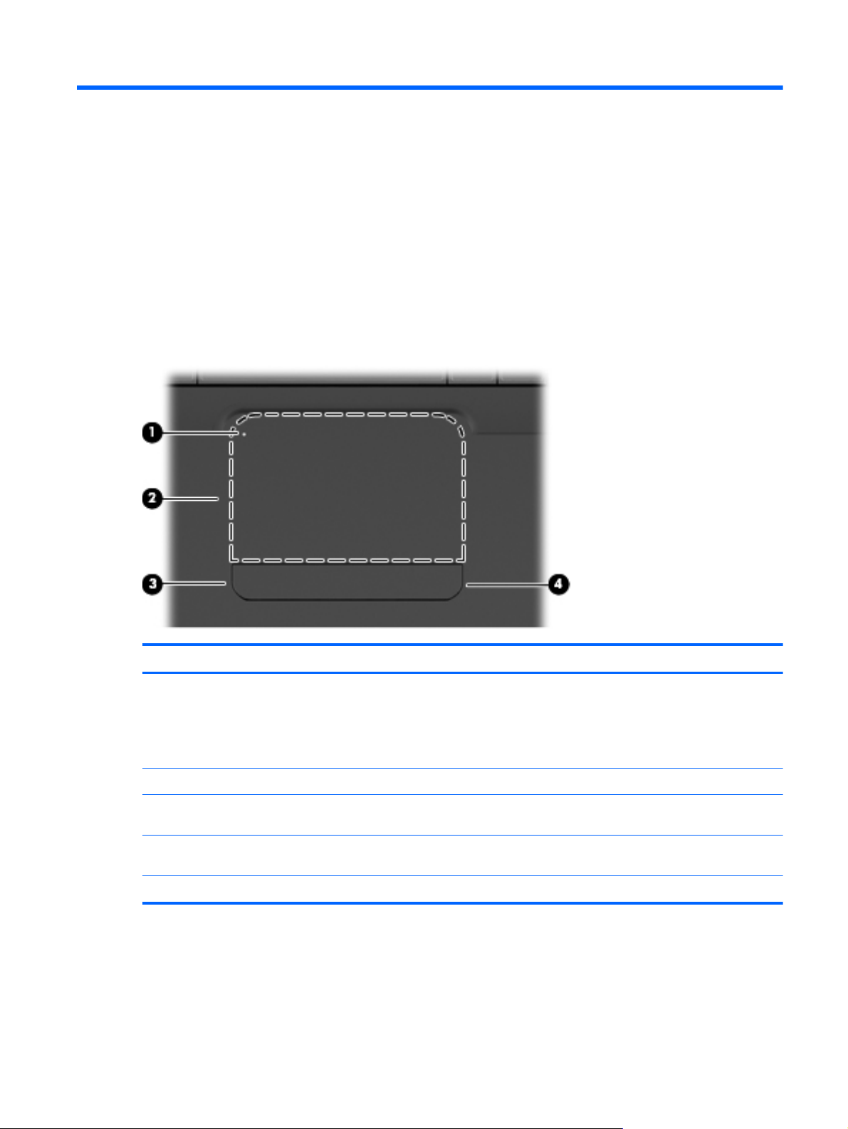
TouchPad
Component Description
(1) TouchPad light To turn the TouchPad on and off, quickly double-tap the
TouchPad light.
Off: TouchPad is on.
●
Amber: TouchPad is off.
●
(2) TouchPad zone Moves the pointer and selects or activates items on the screen.
(3) Left TouchPad button* Press the left side of the TouchPad button to execute functions
(4) Right TouchPad button* Press the right side of the TouchPad button to execute functions
*This table describes factory settings.
performed by the left button on an external mouse.
performed by the right button on an external mouse.
There is an unmarked scroll zone inside the right edge of the TouchPad. To scroll up and down using
the TouchPad vertical scroll zone, slide your finger up or down inside the right edge of the TouchPad.
Top 5
Page 14
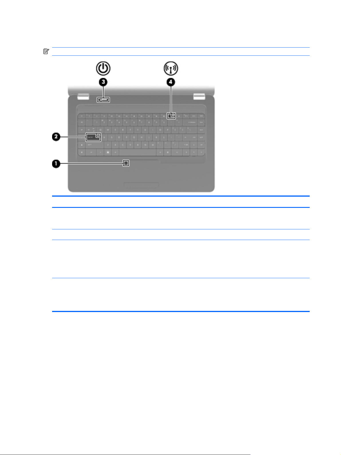
Lights
NOTE: Your computer may look slightly different from the illustration in this section.
Component Description
(1) TouchPad light
(2) Caps lock light On: Caps lock is on.
(3) Power light
(4) Wireless light
Off: TouchPad is on.
●
Amber: TouchPad is off.
●
On: The computer is on.
●
Blinking: The computer is in the Sleep state (Windows) or
●
Suspend state (Linux).
Off: The computer is off or in Hibernation.
●
White: An integrated wireless device, such as a wireless
●
local area network (WLAN) device and/or a Bluetooth®
device, is on.
Amber: All wireless devices are off.
●
6 Chapter 2 External component identification
Page 15
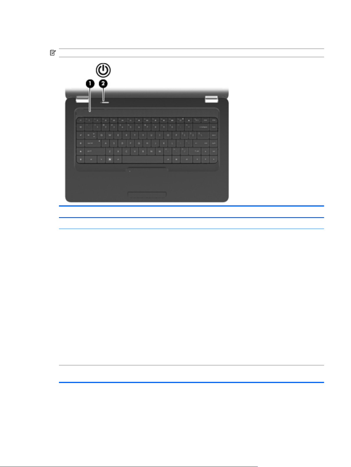
Button and speakers
NOTE: Your computer may look slightly different from the illustration in this section.
Component Description
(1) Speaker grill Two integrated speakers produce sound.
(2) Power button*
*This table describes factory settings. For information about changing factory settings, press f1 to open Help and Support
(Windows) or Help (Linux).
When the computer is off, press the button to turn on the
●
computer.
When the computer is on, press the button briefly to initiate
●
Sleep.
When the computer is in the Sleep state, press the button
●
briefly to exit Sleep.
When the computer is in Hibernation, press the button
●
briefly to exit Hibernation.
If the computer has stopped responding and shutdown
procedures are ineffective, press and hold the power button for
at least 5 seconds to turn off the computer.
To learn more about your power settings:
In Windows, select Start > Control Panel > System and
●
Security > Power Options
In Linux, select Computer > Control Center > System >
●
Power Management
Top 7
Page 16
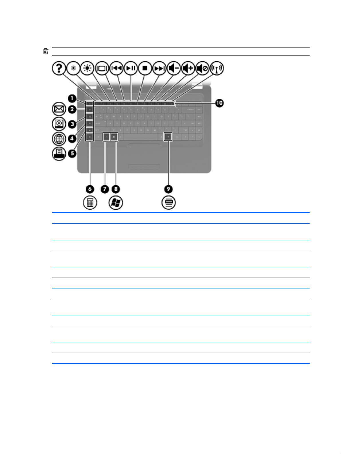
Keys
NOTE: Your computer may look slightly different from the illustration in this section.
Component Description
(1) esc key* Displays system information when pressed in combination with
(2) Send e-mail key Opens a new e-mail in your default e-mail client.
(3) Media application key Launches CyberLink PowerDVD (Windows) or the default media
(4) Web browser key Launches your default web browser.
(5) Print key Sends the currently-active document to the default printer.
(6) Calculator key Launches the calculator application.
(7) fn key* Displays system information when pressed in conjunction with
(8) Windows logo key Displays the Windows or Linux Start menu (varies by model).
(9) Windows applications key (varies by
model)
(10) Action keys Execute frequently-used system actions.
*Supported on Windows models only.
the fn key.
player (Linux).
the esc key.
Displays a shortcut menu for items where the cursor is
positioned.
8 Chapter 2 External component identification
Page 17
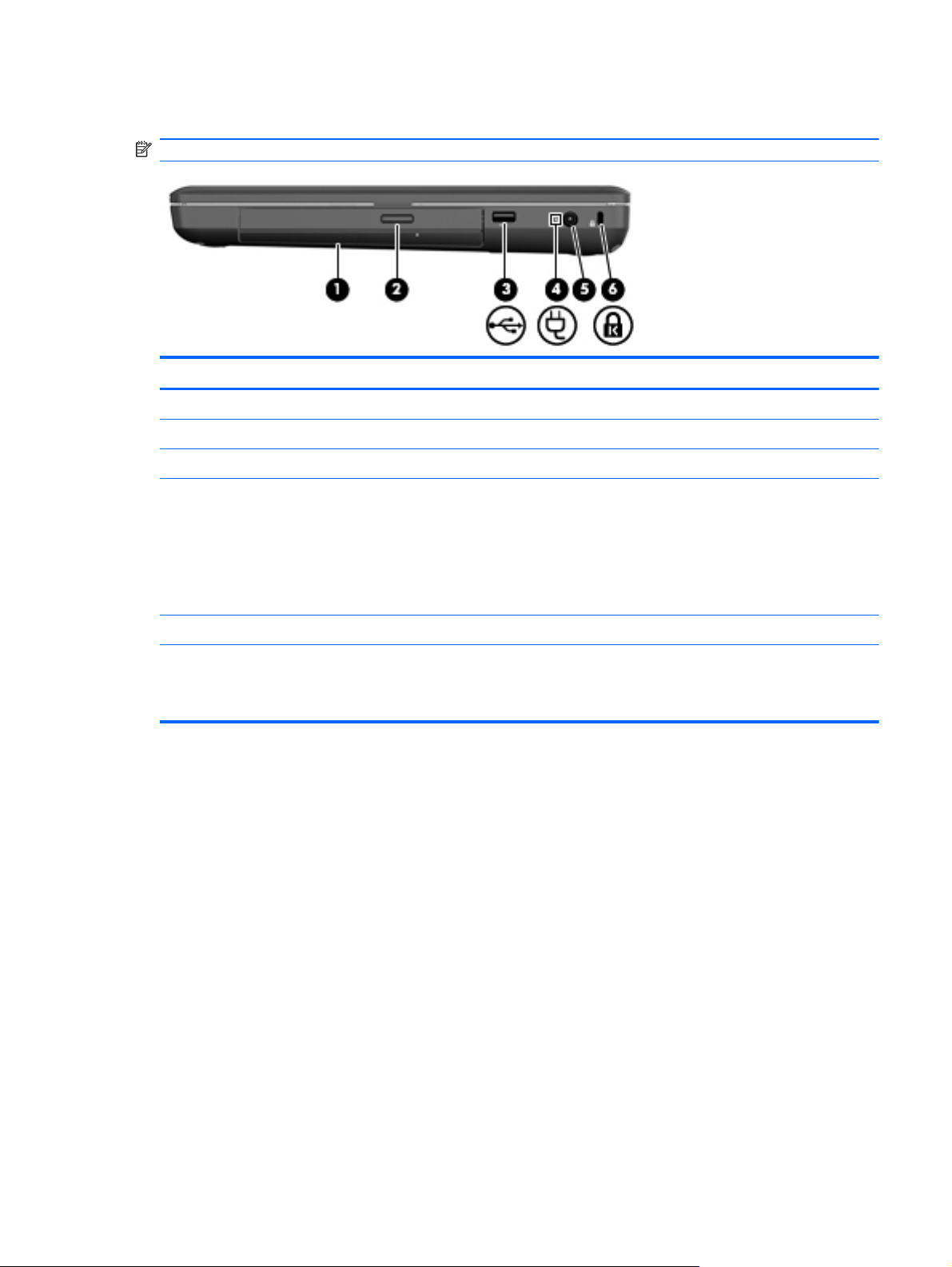
Right side
NOTE: Your computer may look slightly different from the illustration in this section.
Component Description
(1) Optical drive (select models only) Reads and writes to an optical disc.
(2) Optical drive light (select models only) Blinking: The optical drive is being accessed.
(3) USB port Connects an optional USB device.
(4) AC adapter light
(5) Power connector Connects an AC adapter.
(6) Security cable slot Attaches an optional security cable to the computer.
Blinking white: The computer is in the Sleep state
●
(Windows) or Suspend state (Linux).
White: The computer is connected to external power.
●
Amber: The computer is charging.
●
Off: The computer is not connected to external power.
●
NOTE: The security cable is designed to act as a deterrent, but
it may not prevent the computer from being mishandled or stolen.
Right side 9
Page 18
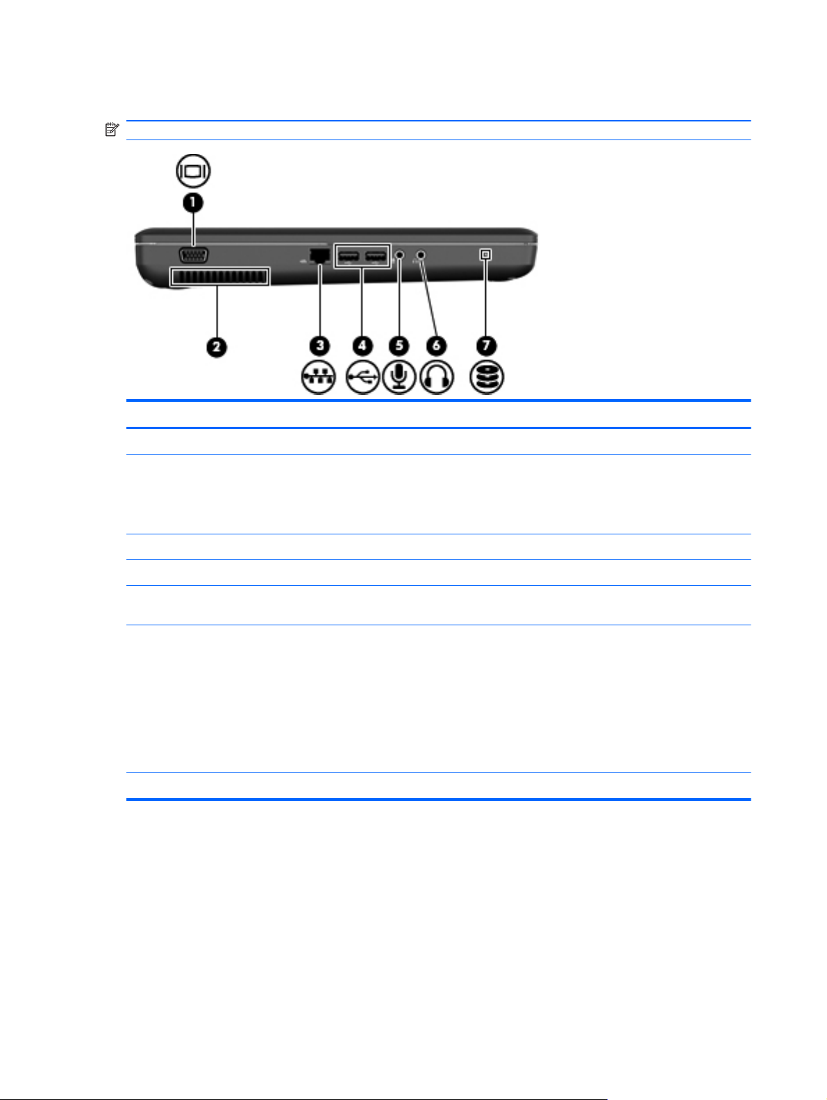
Left side
NOTE: Your computer may look slightly different from the illustration in this section.
Component Description
(1) External monitor port Connects an external VGA monitor or projector.
(2) Vent Enables airflow to cool internal components.
NOTE: The computer fan starts up automatically to cool internal
components and prevent overheating. It is normal for the internal
fan to cycle on and off during routine operation.
(3) RJ-45 (network) jack Connects a network cable.
(4) USB ports (2) Connect optional USB devices.
(5) Audio-in (microphone) jack Connects an optional computer headset microphone, stereo
array microphone, or monaural microphone.
(6) Audio-out (headphone) jack Produces sound when connected to optional powered stereo
speakers, headphones, earbuds, a headset, or television audio.
WARNING! To reduce the risk of personal injury, adjust the
volume before putting on headphones, earbuds, or a headset.
For additional safety information, refer to the Regulatory, Safety,
and Environmental Notices.
NOTE: When a device is connected to the headphone jack, the
computer speakers are disabled.
(7) Drive light On: The hard drive is in use.
10 Chapter 2 External component identification
Page 19
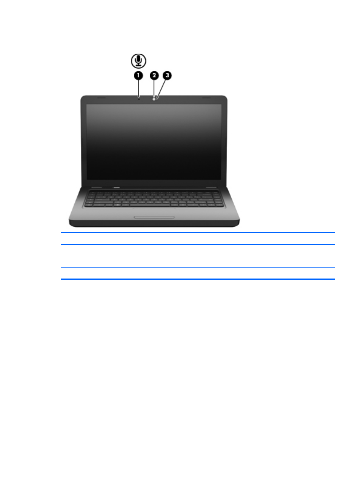
Display
Component Description
(1) Internal microphone (select models only) Records sound.
(2) Webcam (select models only) Records video and captures still photographs.
(3) Webcam light (select models only) On: The webcam is in use.
Display 11
Page 20
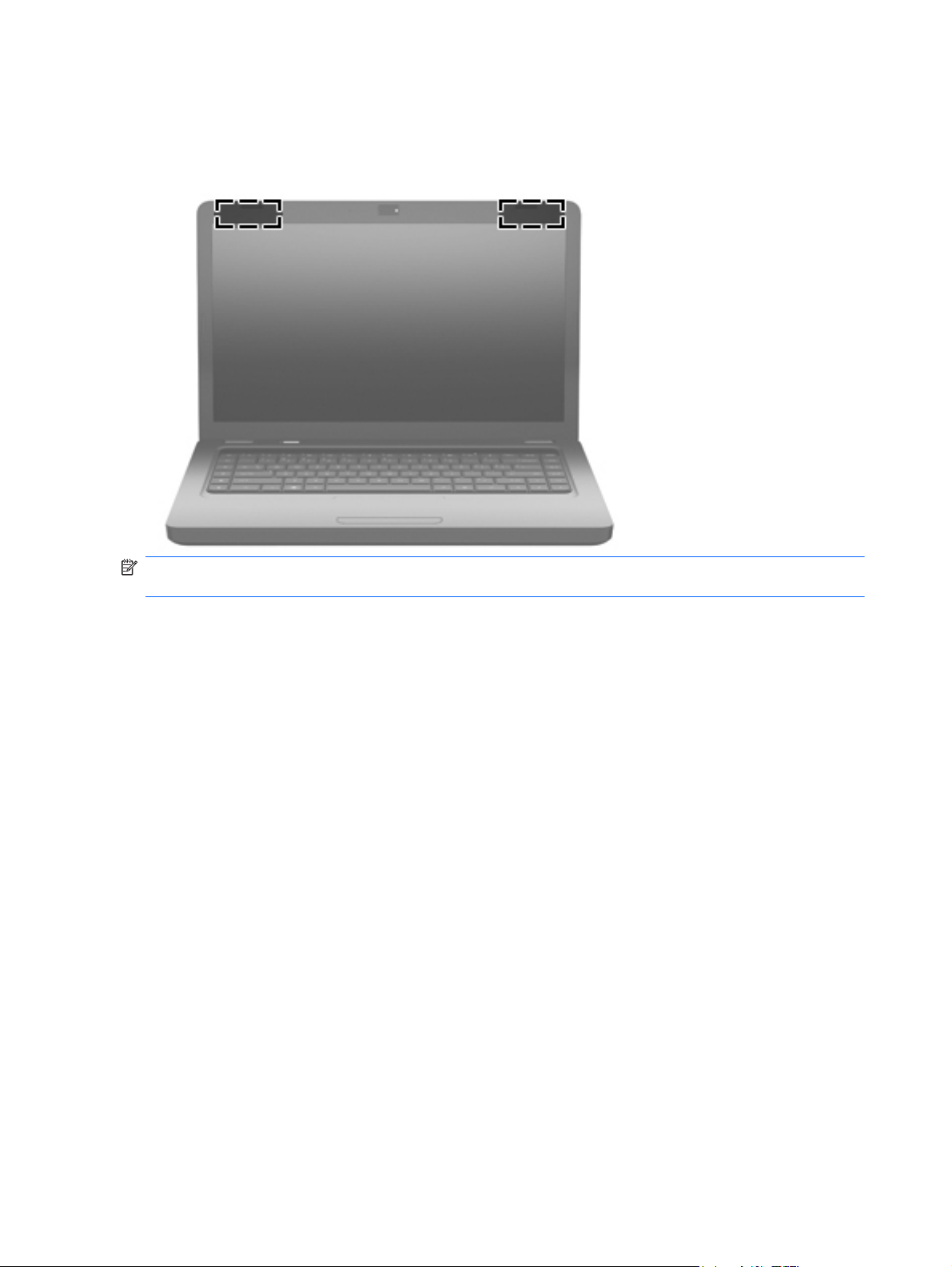
Wireless antennas
Your computer model has two antennas that send and receive signals from one or more wireless
devices. These antennas are not visible from the outside of the computer.
NOTE: For optimal transmission, keep the areas immediately around the antennas (shown in the
previous illustration) free from obstructions.
To see wireless regulatory notices, refer to the section of the Regulatory, Safety and Environmental
Notices that applies to your country or region. These notices are located in Help and Support
(Windows) and Help (Linux).
12 Chapter 2 External component identification
Page 21
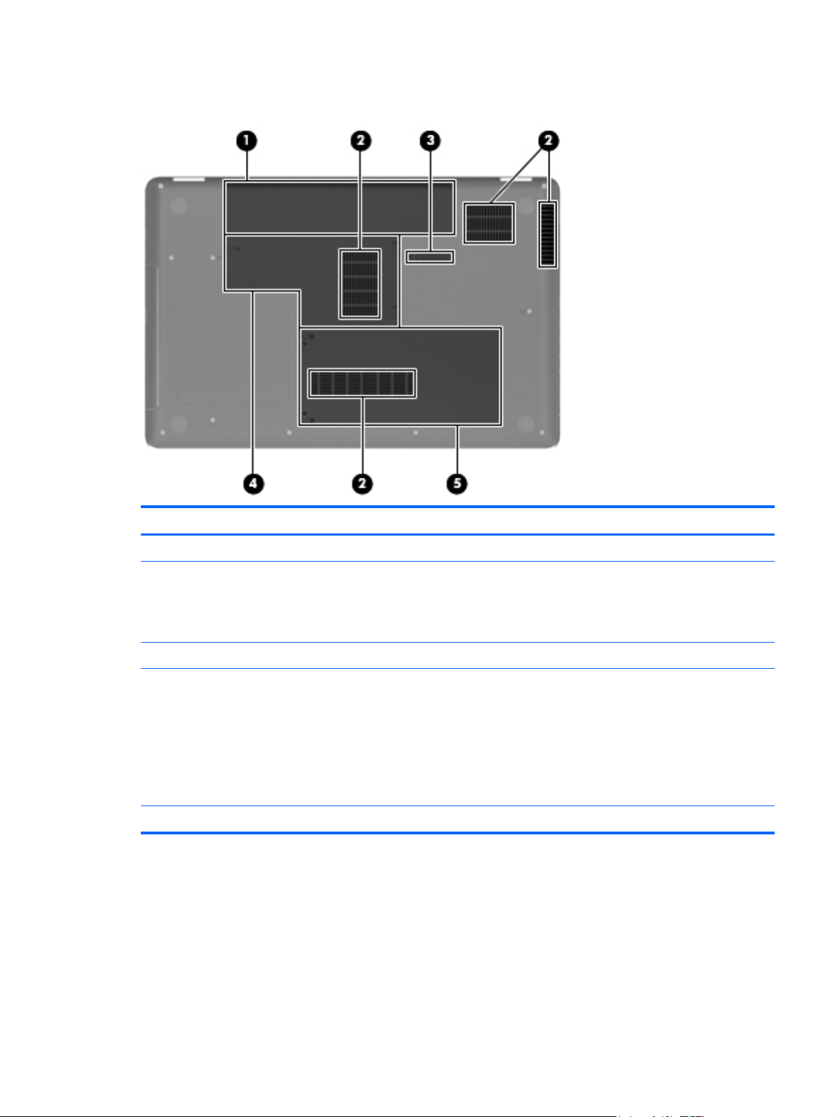
Bottom
Component Description
(1) Battery bay Holds the battery.
(2) Vents (4) Enable airflow to cool internal components.
NOTE: The computer fan starts up automatically to cool internal
components and prevent overheating. It is normal for the internal
fan to cycle on and off during routine operation.
(3) Battery release latch Releases the battery from the battery bay.
(4) Memory module compartment Contains two memory module slots and WLAN slot.
CAUTION: To prevent an unresponsive system, replace the
wireless module only with a wireless module authorized for use in
the computer by the governmental agency that regulates wireless
devices in your country or region. If you replace the module and
then receive a warning message, remove the module to restore
computer functionality, and then contact technical support
through Help and Support.
(5) Hard drive bay Holds the hard drive.
Bottom 13
Page 22
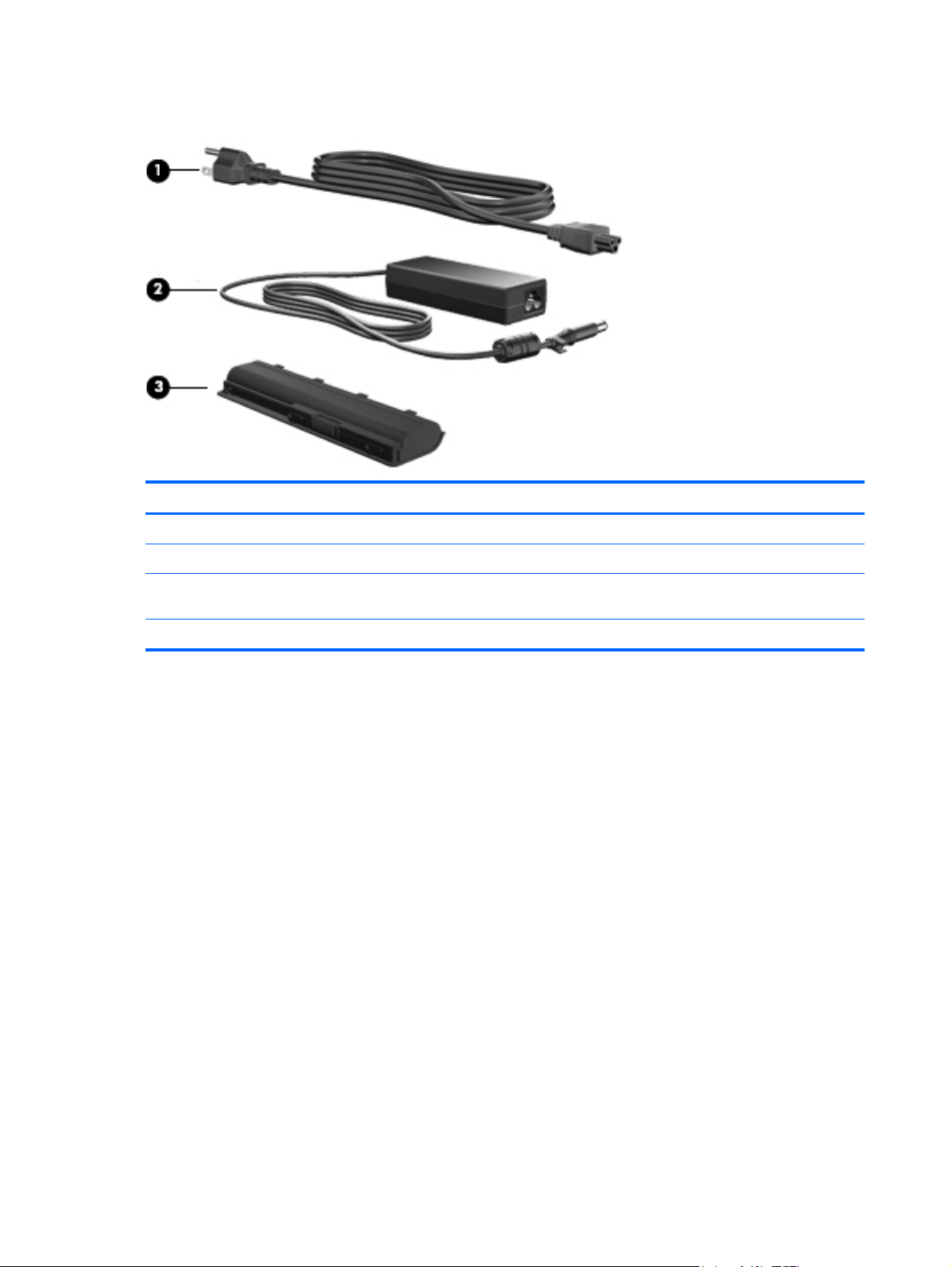
Additional hardware
Component Description
(1) Power cord* Connects an AC adapter to an AC outlet.
(2) AC adapter Converts AC power to DC power.
(3) Battery* Powers the computer when the computer is not plugged into
external power.
*Batteries and power cords vary in appearance by region or country.
14 Chapter 2 External component identification
Page 23
3 Illustrated parts catalog
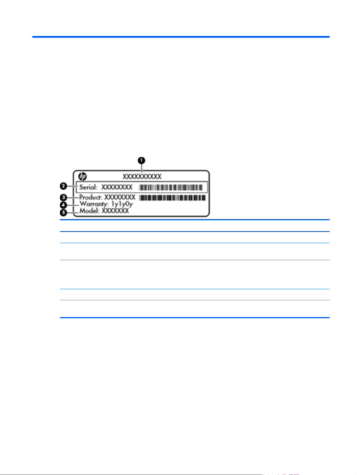
Service tag
When ordering parts or requesting information, provide the computer serial number and model
description provided on the service tag.
Component Description
(1) Product name The product name affixed to the front of your computer.
(2) Serial number (s/n) An alphanumeric number that is unique to each
product.
(3) Part number/Product number (p/n) The number that provides specific information about the
product's hardware components. The part number
helps a service technician to determine what
components and parts are needed.
(4) Warranty period The duration of the warranty period for this computer.
(5) Model description The alphanumeric identifier you need to locate
documents, drivers, and support for your computer.
Service tag 15
Page 24
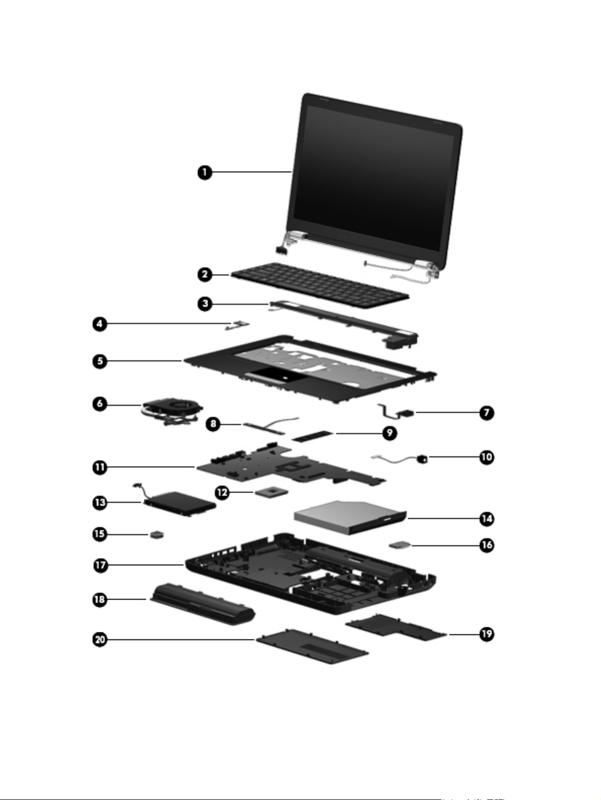
Computer major components
16 Chapter 3 Illustrated parts catalog
Page 25

Item Description Spare part number
(1) Display assembly
NOTE: For more display assembly internal component spare part information. See
Display assembly components on page 20.
(2) Keyboard (includes keyboard cable)
39.6-cm (15.6-in) HD LED BrightView with webcam and microphone display
●
assembly for HP G56 computer
39.6-cm (15.6-in) HD LED BrightView with microphone display assembly for HP
●
G56 computer
39.6-cm (15.6-in) HD CCFL BrightView with webcam and microphone display
●
assembly for HP G56 computer
39.6-cm (15.6-in) HD CCFL BrightView with microphone display assembly for HP
●
G56 computer
39.6-cm (15.6-in) HD LED BrightView with webcam and microphone display
●
assembly for Presario CQ56 computer
39.6-cm (15.6-in) HD LED BrightView with microphone display assembly for
●
Presario CQ56 computer
39.6-cm (15.6-in) CCFL LED BrightView with webcam and microphone display
●
assembly for Presario CQ56 computer
39.6-cm (15.6-in) CCFL LED BrightView with microphone display assembly for
●
Presario CQ56 computer
620589-001
620588-001
620591-00
620590-001
620585-001
620584-001
620587-001
620586-001
For use in Adriatic countries 595199-BA1
●
For use in Belgium 595199-A41
●
For use in Canada 595199-121
●
For use in Czech Republic 595199-221
●
For use in France 595199-051
●
For use in Germany 595199-041
●
For use in Greece 595199-DJ1
●
For use in Hungry 595199-211
●
For International use 595199-B31
●
For use in Israel 595199-BB1
●
For use in Italy 595199-061
●
For use in Japan 595199-291
●
For use in Latin America 595199–161
●
For use in North America 595199-001
●
For use in Norway 595199-DH1
●
For use in Portugal 595199-131
●
For use in Russia 595199-251
●
For use in Saudi Arabia 595199-171
●
Computer major components 17
Page 26

Item Description Spare part number
(3) Speaker assembly (includes cable) 620607-001
(4) Power button board 595204-001
(5) Top cover (includes TouchPad board) 620605-001
(6) Fan/heat sink assembly (includes replacement thermal material)
(7) USB board 595205-001
(8) TouchPad button board 595203-001
(9) Memory module
For use in Spain 595199-071
●
For use in Switzerland 595199-BG1
●
For use in Turkey 595199-141
●
For use in United Kingdom 595199-031
●
For use with AMD processor models 630722-001
●
For use with Intel processor models 606573-001
●
1-GB (1066 MHz, DDR2, Intel) 619545-001
●
2-GB (1066 MHz, DDR2, Intel) 619546-001
●
1-GB (1333 MHz, DDR3, AMD) 621559-001
●
(10) Power connector (includes cable) 602743-001
(11) System board (includes replacement thermal material):
(12) Processor (includes replacement thermal material)
2-GB (1333 MHz, DDR3, AMD) 621566-001
●
PCA UMA system board (Intel) 623909-001
●
PCA UMA system board (AMD) 623915-001
●
Intel Mobile Celeron 925 processor (2.3 GHz, 1-MB L3 cache, 800 MHz) 636636-001
●
Intel Celeron 900 processor (2.2 GHz) 534419-001
●
Intel Pentium T4500 processor (2.3 GHz) 591880-001
●
Intel Celeron T3500 processor (2.1 GHz) 625830-001
●
AMD V-160 processor (2.4 GHz, 512-MB L2 cache, 1066 MHz, 3.2 GT/s)—single-
●
core 25 W
AMD V140 processor (2.3 GHz, 512-MB, L2 cache, 1066 MHz, 3.2 GT/s)—single-
●
core 25 W
AMD Athlon II N370 processor (2.5 GHz, 1-MB L2 cache, 1066 MHz, 3.2 GT/s)--
●
dual-core 35 W
AMD Athlon II N350 processor (2.4 GHz, 1-MB L2 cache, 1066 MHz, 3.2 GT/s)—
●
dual-core 35 W
636634-001
616333-001
634686-001
616334-001
AMD Athlon II P360 processor (2.3 GHz, 1 MB L2 cache, 3.6 GT/s)—dual-core 25W636635-001
●
18 Chapter 3 Illustrated parts catalog
Page 27

Item Description Spare part number
(13) Hard drive (includes bracket, connector, and screws)
(14) Optical drive (includes bezel and bracket)
DVD±RW SuperMulti Double-Layer Drive with LightScribe 620604-001
(15) RTC battery (includes mounting adhesive) 602745-001
(16) Wireless (WLAN) module
AMD Athlon II P340 processor (2.2 GHz, 1-MB L2 cache, 1066 MHz, 3.2 GT/s)—
●
dual-core 25 W
AMD Athlon II P320 processor (2.1 GHz, 1-MB L2 cache, 1066 MHz, 3.2 GT/s)—
●
dual-core 25 W
500-GB, 5400-rpm 9.5-mm, 6.35-cm (2.5-in) 634932-001
●
320-GB, 7200-rpm 9.5-mm, 6.35-cm (2.5-in) 627731-001
●
250-GB, 7200-rpm 9.5-mm, 6.35-cm (2.5-in) 599054-001
●
Hard Drive Hardware Kit (not illustrated; includes bracket, connector, and screws) 599057-001
●
Atheros AR9285 802.11b/g/n 1x1 WiFi adapter 605560-005
●
Realtek RTL8191SE 802.11b/g/n 1x1 WiFi adapter 593533–001
●
Broadcom 4313 802.11b/g/n 1x1 WiFi adapter (AMD only) 593836-001
●
Broadcom 4313 802.11b/g/n 1x1 WiFi and 2070 Bluetooth 2.1+EDR combo adapter
●
(BT3.0+HS ready)
616343-001
594165-001
600370-001
(17) Base enclosure 620606-001
(18) Battery
Plastics Kit 595200-001
(19)
(20)
Ralink RT3090BC4 802.11b/g/n 1x1 WiFi and Bluetooth 2.1+EDR combo adapter
●
(BT3.0+HS ready)
Ralink RT5390 802.11b/g/n 1x1 WiFi adapter 630703-001
●
6-cell Li-ion, 2.20-Ah, 47-Wh 593553-001
●
6-cell Li-ion, 2.55-Ah, 55-Wh 593554-001
●
Memory module compartment cover
●
Hard drive cover
●
Rubber Kit (not illustrated; includes four rubber feet) 600849-001
602992-001
Computer major components 19
Page 28
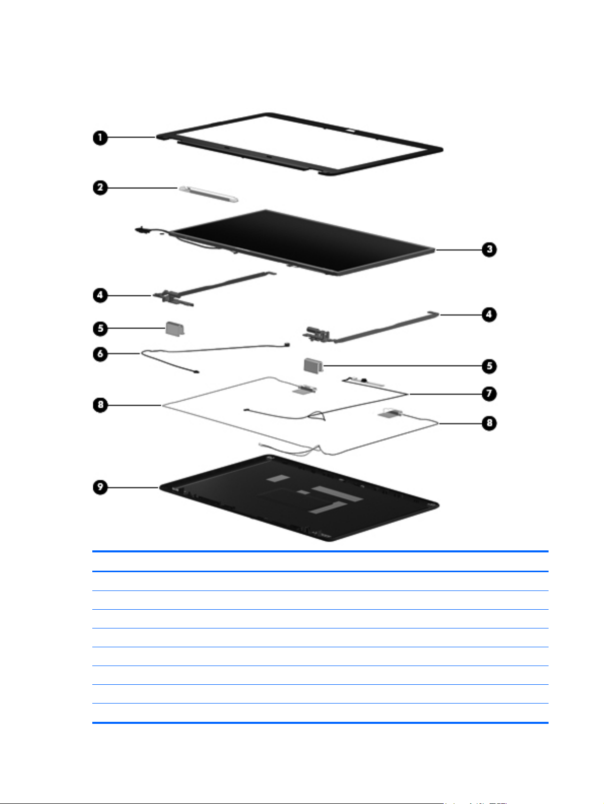
Display assembly components
Item Description Spare part number
(1) Display bezel
(2) Display inverter 616467-001
(3) Display panel
39.6-cm (15.6-in) HD, BrightView, LED display panel (includes display panel cable) 595130-001
Presario CQ56 with webcam and microphone modules 620593-001
●
Presario CQ56 with microphone module only 620592-001
●
HP G56 with webcam and microphone modules 620595-001
●
HP G56 with microphone module only 620594-001
●
20 Chapter 3 Illustrated parts catalog
Page 29

Item Description Spare part number
39.6-cm (15.6-in) HD, BrightView, CCFL display panel (includes backlight cables) 616450-001
(4) Hinge/Bracket Kit (includes left and right brackets)
For use with LED display panels 595195-001
For use with CCFL display panels 616465-001
(5) Display hinge covers 600650-001
(6) Microphone and cable
NOTE: The microphone and cable are included in the display back cover kit.
(7) Webcam module (select models only) 626656-001
(8) Display Cable Kit (includes display cable, wireless antenna module with cable, and
webcam cable)
(9) Display back cover (includes logo):
Display Screw Kit (not illustrated) 595197-001
Display Rubber Kit (not illustrated; includes display bezel rubber screw covers) 595198-001
For use with LED display panels 595196-001
●
For use with CCFL display panels 616466-001
●
For use with HP G56 computer models with LED displays 620601-001
●
For use with Presario CQ56 computer models with LED displays 620600-001
●
For use with HP G56 computer models with CCFL displays 620603-001
●
For use with Presario CQ56 computer models with CCFL displays 620602-001
●
Display assembly components 21
Page 30
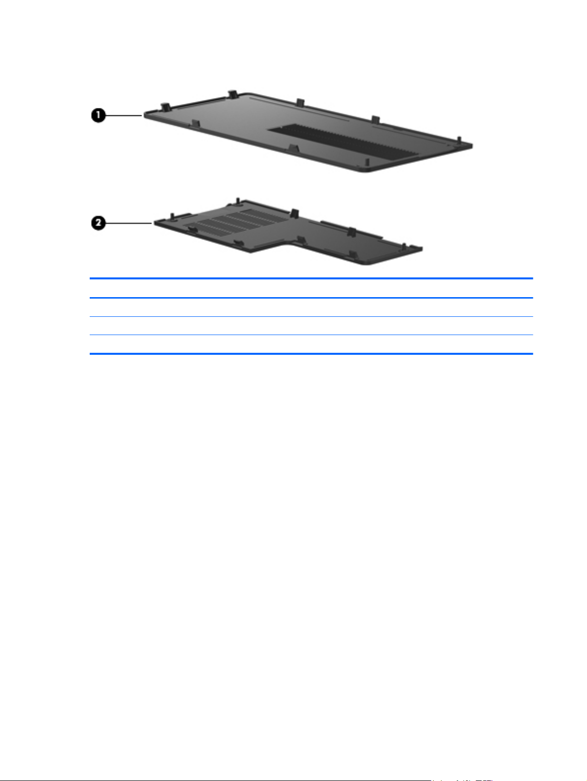
Plastics Kit
Item Description Spare part number
Plastics Kit 595200-001
(1) Hard drive cover (includes captive screws)
(2) Memory module compartment cover (includes captive screw)
22 Chapter 3 Illustrated parts catalog
Page 31

Mass storage devices
Item Description Spare part number
(1) Optical drive (12.7 mm, SATA, fixed, includes bezel and bracket)
DVD±RW SuperMulti Double-Layer Drive with LightScribe 620604-001
(2) Hard drive
Hard Drive Hardware Kit (not illustrated, includes bracket, connector, and screws) 599057-001
500-GB, 5400-rpm 9.5-mm, 6.35-cm (2.5-in) 634932-001
●
320-GB, 7200-rpm 9.5-mm, 6.35-cm (2.5-in) 627731-001
●
250-GB, 7200-rpm 9.5-mm, 6.35-cm (2.5-in) 599054-001
●
Mass storage devices 23
Page 32

Miscellaneous parts
Description Spare part number
AC adapters
65-W, 3-pin Smart AC adapter for use in all countries and regions except India 609939-001
●
65-W, 3-pin Smart AC adapter for use only in India 609948-001
●
Power cord, AC, 3 wire, black, 1.83-m
For use in Argentina 490371-D01
●
For use in Australia 490371-011
●
For use in Denmark 490371-081
●
For use in Europe 490371-021
●
For use in India 490371-D61
●
For use in Israel 490371-BB1
●
For use in Italy 490371-061
●
For use in North America 430971-001
●
For use in South Africa 490371-AR1
●
For use in Switzerland 490371-111
●
For use in United Kingdom and Singapore 490371-031
●
Cable Kit 595201-001
Hard drive connector cable
●
Optical drive connector cable
●
Power button cable
●
TouchPad button board cable
●
TouchPad cable
●
USB cable
●
Modem cable
●
Rubber Kit 600849-001
Screw Kit
Phillips M2.0x3.0 screws
●
Phillips M2.5x3.0 screws
●
Phillips M2.5x4.0 screws
●
Phillips M2.5x5.0 screws
●
Phillips M2.5x6.5 screws
●
595202-001
24 Chapter 3 Illustrated parts catalog
Page 33

Sequential part number listing
Spare part number Description
490371-001 Power cord for use in North America
490371-001 Power cord for use in Australia
490371-021 Power cord for use in Europe
490371-031 Power cord for use in the United Kingdom and Singapore
490371-061 Power cord for use in Italy
490371-081 Power cord for use in Denmark
490371-111 Power cord for use in Switzerland
490371-AR1 Power cord for use in South Africa
490371-BB1 Power cord for use in Israel
490371-D01 Power cord for use in Argentina
504593-003 Broadcom BCM4312 802.11b/g WiFi adapter for use in Canada, the Cayman Islands, Guam,
Puerto Rico, the United States, and the US Virgin Islands
534419-001 Intel Celeron 900 processor (2.2 GHz)
591880-001 Intel Pentium T4500 processor (2.3 GHz)
593533-001 Realtek RTL8191SE 802.11b/g/n 1x1 WiFi adapter
593553-001 Battery, 6-cell, 2.2-Ah, 47-Wh
593554-001 Battery, 6-cell, 2.55-Ah, 55-Wh
593836-001 Broadcom 4313 802.11b/g/n 1x1 WiFi adapter (AMD only)
594165-001 AMD Athlon II P320 processor (2.1 GHz, 1-MB L2 cache, 1066 MHz, 3.2 GT/s)—dual-core 25
W
595130-001 39.6-cm (15.6-in) HD LED BrightView display panel (includes display panel cable)
595195-001 Hinge/Bracket Kit (for use with LED display panels; includes left and right brackets)
595197-001 Display Screw Kit
595198-001 Display Rubber Kit
595199-001 Keyboard for use in North America (includes keyboard cable)
595199-031 Keyboard for use in the United Kingdom (includes keyboard cable)
595199-041 Keyboard for use in Germany (includes keyboard cable)
595199-051 Keyboard for use in France (includes keyboard cable)
595199-061 Keyboard for use in Italy (includes keyboard cable)
595199-071 Keyboard for use in Spain (includes keyboard cable)
595199-121 Keyboard for use in Canada (includes keyboard cable)
595199-131 Keyboard for use in Portugal (includes keyboard cable)
595199-141 Keyboard for use in Turkey (includes keyboard cable)
Sequential part number listing 25
Page 34

Spare part number Description
595199-161 Keyboard for use in Latin America (includes keyboard cable)
595199-171 Keyboard for use in Saudi Arabia (includes keyboard cable)
595199-211 Keyboard for use in Hungary (includes keyboard cable)
595199-221 Keyboard for use in the Czech Republic (includes keyboard cable)
595199-251 Keyboard for use in Russia (includes keyboard cable)
595199-291 Keyboard for use in Japan (includes keyboard cable)
595199-A41 Keyboard for use in Belgium (includes keyboard cable)
595199-B31 Keyboard for international use (includes keyboard cable)
595199-BA1 Keyboard for use in Adriatic countries (includes keyboard cable)
595199-BB1 Keyboard for use in Israel (includes keyboard cable)
595199-BG1 Keyboard for use in Switzerland (includes keyboard cable)
595199-DH1 Keyboard for use in Norway (includes keyboard cable)
595199-DJ1 Keyboard for use in Greece (includes keyboard cable)
595200-001 Plastics Kit
595196-001 Display Cable Kit for use with LED panels (includes display cable, wireless antenna module with
cable, and webcam cable)
595202-001 Screw Kit
595203-001 TouchPad button board with cable
595204-001 Power button board
595205-001 USB board
599054-001 250-GB, 7200-rpm 9.5-mm, 6.35-cm (2.5-in) hard drive
599057-001 Hard Drive Hardware Kit (includes bracket, connector, and screws)
600370-001 Broadcom 4313 802.11b/g/n 1x1 WiFi and 2070 Bluetooth 2.1+EDR combo adapter (BT3.0+HS
ready)
600650-001 Display hinge covers
600849-001 Rubber Kit (includes four rubber feet)
602743-001 Power connector (includes cable)
602745-001 RTC battery
602992-001 Ralink RT3090BC4 802.11b/g/n 1x1 WiFi and Bluetooth 2.1+EDR combo adapter (BT3.0+HS
ready)
605560-005 Atheros AR9285 802.11b/g/n 1x1 WiFi adapter
606573-001 Fan/heat sink assembly (includes replacement thermal material) for use with UMA systems
(Intel)
609939-001 65-W, 3-pin Smart AC adapter for use in all countries and regions except India
609948-001 65-W, 3-pin Smart AC adapter for use in India
616333-001 AMD V140 processor (2.3 GHz, 512-MB, L2 cache, 1066 MHz, 3.2 GT/s)—single-core 25 W
26 Chapter 3 Illustrated parts catalog
Page 35

Spare part number Description
616334-001 AMD Athlon II N350 processor (2.4 GHz, 1-MB L2 cache, 1066 MHz, 3.2 GT/s)—dual-core 35
W
616343-001 AMD Athlon II P340 processor (2.2 GHz, 1-MB L2 cache, 1066 MHz, 3.2 GT/s)—dual-core 25
W
616450-001 39.6-cm (15.6-in) HD CCFL BrightView display panel (includes display panel cable)
616465-001 Hinge/Bracket Kit (for use with CCFL display panels; includes left and right brackets)
616466-001 Display Cable Kit for use with CCFL panels (includes display cable, wireless antenna module
with cable, and webcam cable)
616467-001 Display inverter
619545-001 1-GB memory module (1066 MHz, DDR2, Intel)
619546-001 2-GB memory module (1066 MHz, DDR2, Intel)
620584-001 39.6-cm (15.6-in) HD LED BrightView display assembly with microphone for Presario CQ56
computer
620585-001 39.6-cm (15.6-in) HD LED BrightView display assembly with webcam and microphone for
Presario CQ56 computer
620586-001 39.6-cm (15.6-in) HD CCFL BrightView display assembly with microphone for Presario CQ56
computer
620587-001 39.6-cm (15.6-in) HD LED BrightView display assembly with microphone for Presario CQ56
computer
620588-001 39.6-cm (15.6-in) HD LED BrightView display assembly with microphone for HP G56 computer
620589-001 39.6-cm (15.6-in) HD LED BrightView display assembly with webcam and microphone for HP
G56 computer
620590-001 39.6-cm (15.6-in) HD CCFL BrightView display assembly with microphone for HP G56
computer
620591-001 39.6-cm (15.6-in) HD CCFL BrightView display assembly with webcam and microphone for HP
G56 computer
620592-001 Display bezel for use with Presario CQ56 with microphone module only
620593-001 Display bezel for use with Presario CQ56 with webcam and microphone modules
620594-001 Display bezel for use with HP G56 with microphone module only
620595-001 Display bezel for use with HP G56 with webcam and microphone modules
620600-001 Display back cover for use with Presario CQ56 computer models with LED displays (includes
logo)
620601-001 Display back cover for use with HP G56 computer models with LED displays (includes logo)
620602-001 Display back cover for use with Presario CQ56 computer models with CCFL displays (includes
logo)
620603-001 Display back cover for use with HP G56 computer models with CCFL displays (includes logo)
620604-001 DVD±RW SuperMulti Double-Layer Drive with LightScribe
620605-001 Top cover (includes TouchPad board)
620606-001 Base enclosure
620607-001 Speaker assembly (includes cable)
Sequential part number listing 27
Page 36

Spare part number Description
621559-001 1-GB memory module (1333-MHz, DDR3, AMD)
621566-001 2-GB memory module (1333-MHz, DDR3, AMD)
623909-001 PCA UMA system board (Intel)
623915-001 PCA UMA system board (AMD)
625830-001 Intel Celeron T3500 processor (2.1 GHz)
626656-001 Webcam module (select models only)
627731-001 320-GB, 7200-rpm 9.5-mm, 6.35-cm (2.5-in) hard drive
630703-001 Ralink RT5390 802.11b/g/n 1x1 WiFi adapter
630722-001 Fan/heat sink assembly (includes replacement thermal material) for use with UMA systems
(AMD)
634686-001 AMD Athlon II N370 processor (2.5 GHz, 1-MB L2 cache, 1066 MHz, 3.2 GT/s)--dual-core 35 W
634932-001 500-GB, 5400-rpm 9.5-mm, 6.35-cm (2.5-in) hard drive
636634-001 AMD V-160 processor (2.4 GHz, 512-MB L2 cache, 1066 MHz, 3.2 GT/s--single-core 25
636635-001 AMD Athlon II P360 processor (2.3 GHz, 1 MB L2 cache, 3.6 GT/s)--dual-core 25 W
636636-001 Intel Mobile Celeron 925 processor (2.3 GHz, 1-MB L3 cache, 800 MHz)
28 Chapter 3 Illustrated parts catalog
Page 37

4 Removal and replacement procedures
Preliminary replacement requirements
Tools required
You will need the following tools to complete the removal and replacement procedures:
Flat-bladed screwdriver
●
Magnetic screwdriver
●
Phillips P0 screwdriver
●
Service considerations
Before disassembly or assembly procedures, review and adhere to all service considerations.
NOTE: As you remove each subassembly from the computer, place the subassembly (and all
accompanying screws) away from the work area to prevent damage.
Plastic parts
CAUTION: Using excessive force during disassembly and reassembly can damage plastic parts.
Use care when handling the plastic parts. Apply pressure only at the points designated in the
maintenance instructions.
Preliminary replacement requirements 29
Page 38

Cables and connectors
CAUTION: When servicing the computer, be sure that cables are placed in their proper locations
during the reassembly process. Improper cable placement can damage the computer.
Cables must be handled with extreme care to avoid damage. Apply only the tension required to
unseat or seat the cables during removal and insertion. Handle cables by the connector whenever
possible. In all cases, avoid bending, twisting, or tearing cables. Be sure that cables are routed in
such a way that they cannot be caught or snagged by parts being removed or replaced. Handle flex
cables with extreme care; these cables tear easily.
Drive handling
CAUTION: Drives are fragile components that must be handled with care. To prevent damage to
the computer, damage to a drive, or loss of information, observe these precautions:
Before removing or inserting a hard drive, shut down the computer. If you are unsure whether the
computer is off or in Hibernation, turn the computer on, and then shut it down through the operating
system.
Before handling a drive, be sure that you are discharged of static electricity. While handling a drive,
avoid touching the connector.
Before removing a diskette drive or optical drive, be sure that a diskette or disc is not in the drive and
be sure that the optical drive tray is closed.
Handle drives on surfaces covered with at least one inch of shock-proof foam.
Avoid dropping drives from any height onto any surface.
After removing a hard drive, an optical drive, or a diskette drive, place it in a static-proof
bag.
Avoid exposing a hard drive to products that have magnetic fields, such as monitors or speakers.
Avoid exposing a drive to temperature extremes or liquids.
If a drive must be mailed, place the drive in a bubble pack mailer or other suitable form of protective
packaging and label the package “FRAGILE.”
30 Chapter 4 Removal and replacement procedures
Page 39

Grounding guidelines
Electrostatic discharge damage
Electronic components are sensitive to electrostatic discharge (ESD). Circuitry design and structure
determine the degree of sensitivity. Networks built into many integrated circuits provide some
protection, but in many cases, ESD contains enough power to alter device parameters or melt
silicon junctions.
A discharge of static electricity from a finger or other conductor can destroy static-sensitive devices or
microcircuitry. Even if the spark is neither felt nor heard, damage might have occurred.
An electronic device exposed to ESD might not be affected at all and can work perfectly throughout a
normal cycle. Or the device might function normally for a while, then degrade in the internal layers,
reducing its life expectancy.
CAUTION: To prevent damage to the computer when removing or installing internal components,
observe these precautions:
Keep components in their electrostatic-safe containers until you are ready to install them.
Use nonmagnetic tools.
Before touching an electronic component, discharge static electricity by using the guidelines
described in this section.
Avoid touching pins, leads, and circuitry. Handle electronic components as little as possible.
If you remove a component, place it in an electrostatic-safe container.
The following table shows how humidity affects the electrostatic voltage levels generated by different
activities.
CAUTION: A product can be degraded by as little as 700 V.
Typical electrostatic voltage levels
Relative humidity
Event 10% 40% 55%
Walking across carpet 35,000 V 15,000 V 7,500 V
Walking across vinyl floor 12,000 V 5,000 V 3,000 V
Motions of bench worker 6,000 V 800 V 400 V
Removing DIPS from plastic tube 2,000 V 700 V 400 V
Removing DIPS from vinyl tray 11,500 V 4,000 V 2,000 V
Removing DIPS from Styrofoam 14,500 V 5,000 V 3,500 V
Removing bubble pack from PCB 26,500 V 20,000 V 7,000 V
Packing PCBs in foam-lined box 21,000 V 11,000 V 5,000 V
Preliminary replacement requirements 31
Page 40

Packaging and transporting guidelines
Follow these grounding guidelines when packaging and transporting equipment:
To avoid hand contact, transport products in static-safe tubes, bags, or boxes.
●
Protect ESD-sensitive parts and assemblies with conductive or approved containers or
●
packaging.
Keep ESD-sensitive parts in their containers until the parts arrive at static-free workstations.
●
Place items on a grounded surface before removing items from their containers.
●
Always be properly grounded when touching a component or assembly.
●
Store reusable ESD-sensitive parts from assemblies in protective packaging or nonconductive
●
foam.
Use transporters and conveyors made of antistatic belts and roller bushings. Be sure that
●
mechanized equipment used for moving materials is wired to ground and that proper materials
are selected to avoid static charging. When grounding is not possible, use an ionizer to dissipate
electric charges.
Workstation guidelines
Follow these grounding workstation guidelines:
Cover the workstation with approved static-shielding material.
●
Use a wrist strap connected to a properly grounded work surface and use properly grounded
●
tools and equipment.
Use conductive field service tools, such as cutters, screwdrivers, and vacuums.
●
When fixtures must directly contact dissipative surfaces, use fixtures made only of static-safe
●
materials.
Keep the work area free of nonconductive materials, such as ordinary plastic assembly aids and
●
Styrofoam.
Handle ESD-sensitive components, parts, and assemblies by the case or PCM laminate. Handle
●
these items only at static-free workstations.
Avoid contact with pins, leads, or circuitry.
●
Turn off power and input signals before inserting or removing connectors or test equipment.
●
32 Chapter 4 Removal and replacement procedures
Page 41

Equipment guidelines
Grounding equipment must include either a wrist strap or a foot strap at a grounded workstation.
When seated, wear a wrist strap connected to a grounded system. Wrist straps are flexible
●
straps with a minimum of one megohm ±10% resistance in the ground cords. To provide proper
ground, wear a strap snugly against the skin at all times. On grounded mats with banana-plug
connectors, use alligator clips to connect a wrist strap.
When standing, use foot straps and a grounded floor mat. Foot straps (heel, toe, or boot straps)
●
can be used at standing workstations and are compatible with most types of shoes or boots. On
conductive floors or dissipative floor mats, use foot straps on both feet with a minimum of one
megohm resistance between the operator and ground. To be effective, the conductive strips
must be worn in contact with the skin.
The following grounding equipment is recommended to prevent electrostatic damage:
Antistatic tape
●
Antistatic smocks, aprons, and sleeve protectors
●
Conductive bins and other assembly or soldering aids
●
Nonconductive foam
●
Conductive tabletop workstations with ground cords of one megohm resistance
●
Static-dissipative tables or floor mats with hard ties to the ground
●
Field service kits
●
Static awareness labels
●
Material-handling packages
●
Nonconductive plastic bags, tubes, or boxes
●
Metal tote boxes
●
Electrostatic voltage levels and protective materials
●
The following table lists the shielding protection provided by antistatic bags and floor mats.
Material Use Voltage protection level
Antistatic plastic Bags 1,500 V
Carbon-loaded plastic Floor mats 7,500 V
Metallized laminate Floor mats 5,000 V
Preliminary replacement requirements 33
Page 42

Component replacement procedures
This chapter provides removal and replacement procedures.
There are as many as 67 screws, in 10 different sizes, that must be removed, replaced, or loosened
when servicing the computer. Make special note of each screw size and location during removal and
replacement.
Service tag
When you order parts or request information, provide the computer serial number and model number
provided on the service tag, located inside the battery bay.
Component Description
(1) Part number The number that provides specific information about the product's hardware
components. The part number helps a service technician to determine what
components and parts are needed.
(2) Serial number An alphanumeric number that is unique to each product.
(3) Product information The product name affixed to the front of your computer.
(4) Warranty period The duration of the warranty period for this computer.
(5) Model description The alphanumeric identifier you need to locate documents, drivers, and support
for your computer.
34 Chapter 4 Removal and replacement procedures
Page 43

Computer feet
Description Spare part number
Rubber Kit (includes computer feet) 600849-001
The computer feet are adhesive-backed rubber pads. The feet attach to the base enclosure in the
locations illustrated below.
Component replacement procedures 35
Page 44

Battery
Description Spare part number
6 cell, 2.20-Ah, 47-Wh 593553-001
6 cell, 2.55-Ah, 55-Wh 593554-001
Before removing the battery, follow these steps:
1. Shut down the computer. If you are unsure whether the computer is off or in Hibernation, turn
the computer on, and then shut it down through the operating system.
2. Disconnect all external devices connected to the computer.
3. Disconnect the power from the computer by first unplugging the power cord from the AC outlet
and then unplugging the AC adapter from the computer.
Remove the battery:
1. Position the computer upside down on a flat surface, with the battery bay toward you.
2. Slide the battery release latch (1) to release the battery.
3. Pivot the battery (2) upward and lift it out of the computer (3).
To insert the battery, insert the rear edge of the battery into the battery bay and pivot the front edge
downward until the battery is seated. The battery release latch automatically locks the battery into
place.
36 Chapter 4 Removal and replacement procedures
Page 45

Hard drive
NOTE: The hard drive spare part kit includes a bracket, connector, and screws. The bracket,
connector, and screws are also available in the Hard Drive Hardware Kit.
Description Spare part number
500-GB, 5400-rpm 9.5-mm, 6.35-cm (2.5-in) 634932-001
320-GB, 7200-rpm 9.5-mm, 6.35-cm (2.5-in)
250-GB, 7200-rpm 9.5-mm, 6.35-cm (2.5-in) 599054-001
Hard Drive Hardware Kit (not illustrated; includes bracket, connector, and screws) 599057-001
627731-001
Before removing the hard drive:
1. Shut down the computer. If you are unsure whether the computer is off or in Hibernation, turn on
the computer, and then shut it down through the operating system.
2. Disconnect all external devices connected to the computer.
3. Disconnect the power from the computer by first unplugging the power cord from the AC outlet
and then unplugging the AC adapter from the computer.
4. Remove the battery (see
Battery on page 36)
Remove the hard drive:
1. Position the computer upside down, with the front toward you.
2. Loosen the two Phillips 2.5×5.0 captive screws (1) that secure the hard drive cover to the
computer.
3. Lift the left side of the hard drive cover (2), swing it up, and then remove the cover (3). The hard
drive cover is included in the Plastics Kit, spare part number 595200-001.
4. Remove the three Phillips 2.5×5.0 screws (1) that secure the hard drive to the computer.
Component replacement procedures 37
Page 46

5. Use the Mylar tab (2) to lift the hard drive out of the hard drive compartment.
6. Disconnect the hard drive cable from the system board (3) and remove the hard drive from the
computer (4).
7. To replace the hard drive bracket, remove the four Phillips 3.0×3.5 screws (1) that secure the
hard drive bracket to the hard drive.
8. Grasp the attached Mylar tab and pull it up to remove the bracket from the hard drive (2).
Reverse this procedure to reassemble and install the hard drive.
38 Chapter 4 Removal and replacement procedures
Page 47

Optical drive
NOTE: The optical drive spare part kit includes a bezel and bracket.
Description Spare part number
DVD±RW SuperMulti Double-Layer Drive with LightScribe 620604-001
Before removing the optical drive:
1. Shut down the computer. If you are unsure whether the computer is off or in Hibernation, turn on
the computer, and then shut it down through the operating system.
2. Disconnect all external devices connected to the computer.
3. Disconnect the power from the computer by first unplugging the power cord from the AC outlet
and then unplugging the AC adapter from the computer.
4. Remove the following components:
a. Battery (see
b. Hard drive (see
Battery on page 36).
Hard drive on page 37).
Remove the optical drive:
1. Position the computer upside down, with the front toward you.
Component replacement procedures 39
Page 48

2. Remove the optical drive screw.
3. Insert a thin tool, such as a screwdriver (1), into the release access slot in the hard drive bay,
and press against the back of the optical drive.
40 Chapter 4 Removal and replacement procedures
Page 49

4. Grasp the drive (2) and remove it from the optical drive bay.
Reverse this procedure to reassemble and install the optical drive.
Component replacement procedures 41
Page 50

WLAN module
Description Spare part
Atheros AR9285 802.11b/g/n 1x1 WiFi adapter 605560-005
Realtek RTL8191SE 802.11b/g/n 1x1 WiFi adapter 593533-001
Broadcom 4313 802.11b/g/n 1x1 WiFi adapter 593836-001
Broadcom 4313 802.11b/g/n 1x1 WiFi and 2070 Bluetooth 2.1+EDR Combo adapter (BT3.0+HS ready) 600370-001
Ralink RT3090BC4 802.11b/g/n 1x1 WiFi and Bluetooth 2.1+EDR Combo adapter (BT3.0+HS ready) 602992-001
Ralink RT5390 802.11b/g/n 1x1 WiFi adapter 630703-001
number
Before removing the WLAN module:
1. Shut down the computer. If you are unsure whether the computer is off or in Hibernation, turn on
the computer, and then shut it down through the operating system.
2. Disconnect all external devices connected to the computer.
3. Disconnect the power from the computer by first unplugging the power cord from the AC outlet
and then unplugging the AC adapter from the computer.
4. Remove the battery (see
Battery on page 36).
Remove the WLAN module:
1. Position the computer upside down, with the front toward you.
2. Loosen the three Phillips 2.5×5.0 captive screws (1) that secure the memory module
compartment cover.
3. Lift the outside edge of the memory module cover (2), and remove the cover (3). The memory
module compartment cover is included in the Plastics Kit, spare part number 595200-001.
42 Chapter 4 Removal and replacement procedures
Page 51

4. Disconnect the main antenna cable (1) and the auxiliary antenna cable (2) from the wireless
module.
5. Remove the Phillips 2.0×3.0 screw (3) that secures the WLAN module to the computer. (The
edge of the module opposite the slot rises away from the computer.)
6. Remove the WLAN module (4) by pulling it away from the slot at an angle.
CAUTION: To prevent an unresponsive system, replace the wireless module only with a
wireless module authorized for use in the computer by the governmental agency that regulates
wireless devices in your country or region. If you replace the module and then receive a warning
message, remove the module to restore computer functionality, and then contact technical
support through Help and Support (Windows) or Help (Linux).
NOTE: WLAN modules are designed with a notch (5) to prevent incorrect insertion into the
WLAN module slot.
Reverse this procedure to install the WLAN module.
Component replacement procedures 43
Page 52

Memory module
Description Spare part number
1 GB, 1066 MHz DDR2 (Intel) 619545-001
2 GB, 1066 MHz DDR2 (Intel) 619546-001
1 GB, 1333 MHz, DDR3 (AMD) 621559-001
2 GB, 1333 MHz, DDR3, (AMD) 621566-001
Before removing a memory module:
1. Shut down the computer. If you are unsure whether the computer is off or in Hibernation, turn on
the computer, and then shut it down through the operating system.
2. Disconnect all external devices connected to the computer.
3. Disconnect the power from the computer by first unplugging the power cord from the AC outlet
and then unplugging the AC adapter from the computer.
4. Remove the battery (see
Battery on page 36).
Remove the memory module:
1. Position the computer upside down, with the front toward you.
2. Loosen the three Phillips 2.5×5.0 captive screws (1) that secure the memory module
compartment cover to the computer.
3. Lift the outside edge of the memory module cover (2), and remove the cover (3). The memory
module compartment cover is included in the Plastics Kit, spare part number 595200-001.
NOTE: Small tabs hold the cover in place. Firmly pull up on the cover to release the tabs.
44 Chapter 4 Removal and replacement procedures
Page 53

4. Spread the retaining tabs (1) on each side of the memory module slot to release the memory
module. (The edge of the module opposite the slot rises away from the computer.)
5. Remove the module (2) by pulling it away from the slot at an angle.
NOTE: Memory modules are designed with a notch (3) to prevent incorrect insertion into the
memory module slot.
Reverse this procedure to install a memory module.
Component replacement procedures 45
Page 54

Keyboard
Description Spare part number
For use in Adriatic countries 595199-BA1
For use in Belgium 595199-A41
For use in Canada 595199-121
For use in the Czech Republic 595199-221
For use in France 595199-051
For use in Germany 595199-041
For use in Greece 595199-DJ1
For use in Hungary 595199-211
For International use 595199-B31
For use in Israel 595199-BB1
For use in Italy 595199-061
For use in Japan 595199-291
For use in Latin America 595199-161
For use in North America 595199-001
For use in Norway 595199-DH1
For use in Portugal 595199-131
For use in Russia 595199-251
For use in Saudi Arabia 595199-171
For use in Spain 595199-071
For use in Switzerland 595199-BG1
For use in Turkey 595199-141
For use in the United Kingdom 595199-031
Before removing the keyboard:
1. Shut down the computer. If you are unsure whether the computer is off or in Hibernation, turn on
the computer, and then shut it down through the operating system.
2. Disconnect all external devices connected to the computer.
3. Disconnect the power from the computer by first unplugging the power cord from the AC outlet
and then unplugging the AC adapter from the computer.
4. Remove the following components:
a. Battery (see
Battery on page 36).
b. Remove the memory module compartment cover (see
46 Chapter 4 Removal and replacement procedures
WLAN module on page 42 )
Page 55

Remove the keyboard:
1. Position the computer upside down, with the front toward you.
2. Remove the three Phillips 2.5×5.0 and three Phillips 2.5×6.0 screws that secure the keyboard to
the computer.
3. Position the computer right-side up, with the front toward you.
4. Open the computer as far as possible.
5. Release the tabs along the left (1) and right (2) edges of the keyboard using a thin, flat-bladed
screwdriver.
6. Lift the rear edge of the keyboard (3).
Component replacement procedures 47
Page 56

7. Release the zero insertion force (ZIF) connector (1) to which the keyboard cable is attached and
disconnect the keyboard cable (2) from the system board.
8. Remove the keyboard.
Reverse this procedure to install the keyboard.
48 Chapter 4 Removal and replacement procedures
Page 57

Top cover
Description Spare part number
Top cover (includes TouchPad board) 620605-001
Before removing the top cover:
1. Shut down the computer. If you are unsure whether the computer is off or in Hibernation, turn on
2. Disconnect all external devices connected to the computer.
3. Disconnect the power from the computer by first unplugging the power cord from the AC outlet
4. Remove the following components:
the computer, and then shut it down through the operating system.
and then unplugging the AC adapter from the computer.
a. Battery (see
b. Hard drive cover (see
c. WLAN module (see
d. Keyboard (see
Battery on page 36).
Hard drive on page 37).
WLAN module on page 42).
Keyboard on page 46).
Remove the top cover:
1. Position the computer upside down, with the front toward you.
2. Remove four Phillips 2.0×3.0 screws in the battery bay, and remove ten Phillips 2.0×6.5 screws
on the base enclosure. The top cover screws are identified by a triangle icon embossed on the
base enclosure.
3. Postion the computer right-side up, with the front toward you.
4. Open the computer as far as possible.
Component replacement procedures 49
Page 58

5. Remove the Phillips 2.0×5.0 screw that secures the top cover to the computer.
6. Release the speaker cable (1), power button ZIF connector (2), TouchPad ZIF connector (3),
and TouchPad button ZIF connector (4).
7. Lift the rear edge of the top cover (1) until the top cover disengages from the base enclosure.
50 Chapter 4 Removal and replacement procedures
Page 59

8. Remove the top cover (2).
NOTE: The TouchPad is glued to the top cover and is included with the top cover spare part.
Reverse this procedure to install the top cover.
Component replacement procedures 51
Page 60

Speaker assembly
Description Spare part number
Speaker assembly (includes cable) 620607-001
Before removing the speaker assembly:
1. Shut down the computer. If you are unsure whether the computer is off or in Hibernation, turn on
the computer, and then shut it down through the operating system.
2. Disconnect all external devices connected to the computer.
3. Disconnect the power from the computer by first unplugging the power cord from the AC outlet
and then unplugging the AC adapter from the computer.
4. Remove the following components:
a. Battery (see
b. Hard drive cover (see
c. WLAN module (see
d. Keyboard (see
e. Top cover (see
Battery on page 36)
Hard drive on page 37)
WLAN module on page 42)
Keyboard on page 46 )
Top cover on page 49)
Remove the speaker assembly:
1. Position the top cover upside down.
2. Remove the two Phillips 2.5×3.0 screws (1) that secure the speaker assembly to the top cover.
3. Remove the tape around the speaker cable.
4. Release the speaker from the plastic clip in the center (2).
5. Swing the right edge of the speaker assembly down (3) toward the TouchPad.
52 Chapter 4 Removal and replacement procedures
Page 61

6. Remove the speaker assembly by sliding the left edge (4) from beneath the bracket in the top
cover.
Reverse this procedure to install the speaker assembly.
Component replacement procedures 53
Page 62

Power button board
Description Spare part number
Power button board 595204-001
Before removing the power button board:
1. Shut down the computer. If you are unsure whether the computer is off or in Hibernation, turn on
the computer, and then shut it down through the operating system.
2. Disconnect all external devices connected to the computer.
3. Disconnect the power from the computer by first unplugging the power cord from the AC outlet
and then unplugging the AC adapter from the computer.
4. Remove the following components:
a. Battery (see
b. Hard drive (see
c. WLAN module (see
d. Keyboard (see
e. Top cover (see
Battery on page 36).
Hard drive on page 37)
WLAN module on page 42).
Keyboard on page 46)
Top cover on page 49)
Remove the power button board:
1. Position the top cover upside down, with the rear edge toward you.
2. Remove the Phillips 2.5×3.0 screw (1) that secures the power button board to the top cover.
3. Lift up and remove the power button board (2).
Reverse this procedure to install the power button board.
54 Chapter 4 Removal and replacement procedures
Page 63

TouchPad button board
Description Spare part number
TouchPad button board (with cable) 595203-001
Before removing the TouchPad button board:
1. Shut down the computer. If you are unsure whether the computer is off or in Hibernation, turn on
the computer, and then shut it down through the operating system.
2. Disconnect all external devices connected to the computer.
3. Disconnect the power from the computer by first unplugging the power cord from the AC outlet
and then unplugging the AC adapter from the computer.
4. Remove the following components:
a. Battery (see
b. Hard drive (see
c. WLAN module (see
d. Keyboard (see
e. Top cover (see
Battery on page 36).
Hard drive on page 37)
WLAN module on page 42)
Keyboard on page 46)
Top cover on page 49)
Remove the TouchPad button board:
1. Position the top cover upside down, with the front toward you.
2. Remove the two Phillips 2.5×3.0 screws (1) that secure the TouchPad board to the top cover.
3. Lift up and remove the TouchPad button board (2) from the TouchPad bracket.
Reverse this procedure to install the TouchPad button board.
Component replacement procedures 55
Page 64

USB board
Description Spare part number
USB board 595205-001
Before removing the USB board:
1. Shut down the computer. If you are unsure whether the computer is off or in Hibernation, turn on
2. Disconnect all external devices connected to the computer.
3. Disconnect the power from the computer by first unplugging the power cord from the AC outlet
4. Remove the following components:
the computer, and then shut it down through the operating system.
and then unplugging the AC adapter from the computer.
a. Battery (see
b. Hard drive (see
c. WLAN module (see
d. Keyboard (see
e. Top cover (see
Battery on page 36).
Hard drive on page 37)
WLAN module on page 42).
Keyboard on page 46)
Top cover on page 49)
Remove the USB board:
1. Position the computer upright with the right side toward you.
2. Disconnect the USB board cable (1) from the system board.
3. Remove the Phillips 2.5 x 3.0 screw (2) that secures the USB board to the base enclosure.
4. Lift the USB board (3) straight up to remove it from the computer. The USB cable is available in
the Cable Kit, spare part number 595201-001
56 Chapter 4 Removal and replacement procedures
Page 65

Reverse this procedure to install the USB board.
Component replacement procedures 57
Page 66

Power connector
Description Spare part number
Power connector (includes cable) 602743-001
Before removing the power connector cable:
1. Shut down the computer. If you are unsure whether the computer is off or in Hibernation, turn on
the computer, and then shut it down through the operating system.
2. Disconnect all external devices connected to the computer.
3. Disconnect the power from the computer by first unplugging the power cord from the AC outlet
and then unplugging the AC adapter from the computer.
4. Remove the following components:
a. Battery (see
b. Hard drive (see
c. WLAN module (see
d. Keyboard (see
e. Top cover (see
Battery on page 36)
Hard drive on page 37)
WLAN module on page 42)
Keyboard on page 46)
Top cover on page 49)
Remove the power connector cable:
1. Position the computer upright, with the right side toward you.
2. Disconnect the power connector cable (1) from the system board.
3. Lift the power connector (2) from the clips built into the base enclosure.
Reverse this procedure to install the power connector.
58 Chapter 4 Removal and replacement procedures
Page 67

Display assembly
Description Spare part number
39.6-cm (15.6-in) HD LED BrightView display assembly with webcam and microphone for HP G56
computer
39.6-cm (15.6-in) HD LED BrightView display assembly with microphone for HP G56 computer 620588-001
39.6-cm (15.6-in) HD CCFL BrightView display assembly with webcam and microphone for HP
G56 computer
39.6-cm (15.6-in) HD CCFL BrightView display assembly with microphone for HP G56 computer 620590-001
39.6-cm (15.6-in) HD LED BrightView display assembly with webcam and microphone for
Presario CQ56 computer
39.6-cm (15.6-in) HD LED BrightView display assembly with microphone for Presario CQ56
computer
39.6-cm (15.6-in) HD CCFL BrightView display assembly with webcam and microphone for
Presario CQ56 computer
39.6-cm (15.6-in) HD CCFL BrightView display assembly with microphone for Presario CQ56
computer
620589-001
620591-001
620585-001
620584-001
620587-001
620586-001
Before removing the display assembly:
1. Shut down the computer. If you are unsure whether the computer is off or in Hibernation, turn on
the computer, and then shut it down through the operating system.
2. Disconnect all external devices connected to the computer.
3. Disconnect the power from the computer by first unplugging the power cord from the AC outlet
and then unplugging the AC adapter from the computer.
4. Remove the following components:
a. Battery (see
b. Hard drive cover (see
c. WLAN module (see
d. Optical drive (see
e. Keyboard (see
f. Top cover (see
5. Disconnect the wireless antenna cables from the WLAN module (see
Battery on page 36)
Hard drive on page 37)
WLAN module on page 42)
Optical drive on page 39)
Keyboard on page 46)
Top cover on page 49)
WLAN module
on page 42).
Remove the display assembly:
1. Position the computer right-side up, with the front toward you.
2. Open the display as far as possible.
3. Disconnect the display panel cable (1) and the microphone cable (2) from the system board and
remove them from their routing channels.
Component replacement procedures 59
Page 68

4. Pull the antenna cables through the opening in the top cover (3) and disengage the cables from
the clip in the routing channel leading to the display hinge (4).
5. Disconnect the webcam cable (select models only) (5) from the system board and release it from
the clips that attach it to the system board.
CAUTION: Support the display assembly when removing the display screws in the following
steps. Failure to support the display assembly can result in damage to the assembly and other
components.
6. Remove the four black Phillips 2.5×6.5 screws (1) that secure the display assembly to the
computer.
7. Lift the display panel (2) straight up to remove it.
Reverse this procedure to install the display assembly.
60 Chapter 4 Removal and replacement procedures
Page 69

8. To replace any of the display assembly internal components, remove the following screw covers
and screws:
(1) Two Mylar screw covers on the display bezel bottom edge
(2) Two Phillips 2.5×3.0 screws
The display screw covers are included in the Display Screw Kit, spare part number 595197-001.
9. Flex the inside edge of the top (1), the left and right sides (2), and the bottom (3) of the display
bezel until the bezel disengages from the display back cover.
10. Remove the display bezel (4). The display bezel is available using spare part numbers
620593-001 (for Presario CQ56 models with webcam and microphone modules), 620592-001
(for Presario CQ 56 models with microphone module only), 620595-001 (for HP G56 models
with webcam and microphone modules), and (620594-001 for HP G56 models with microphone
module only).
Reverse this procedure to install the display bezel.
11. To replace the webcam module (select models only), lift the webcam module as far from the
display enclosure as the webcam module cable allows.
Component replacement procedures 61
Page 70

12. Disconnect the webcam module cable (1) from the webcam module, and remove the webcam
module (2). The webcam module is available using spare part number 626656-001.
Reverse this procedure to install the webcam module.
13. To replace the display inverter, disconnect the cables (1) on both sides of the inverter.
14. Then use a flat flexible tool (2) to pry the inverter loose from the adhesive that attaches it to the
display enclosure. The display inverter is available using spare part number 616467-001.
15. To replace the display hinge covers, remove the Phillips 2.5×4.0 screw (1) that secures each
hinge to the display enclosure.
62 Chapter 4 Removal and replacement procedures
Page 71

16. Remove the display hinge covers (2). The display hinge covers are available using spare part
number 600650-001.
Reverse this procedure to install the display hinge covers.
17. To replace the display panel, remove the eight Phillips 2.5 x 4.0 screws (1) that secure the
display panel to the display enclosure.
18. Remove the display panel (2) from the display enclosure. The LED display panel is available
using spare part number 595130-001. The CCFL display panel is available using part number
616450-001.
Reverse this procedure to install the display panel.
19. To replace the display panel brackets, remove the two Phillips 2.0×3.0 screws (1) that secure
each bracket to the display panel.
Component replacement procedures 63
Page 72

20. Remove the display panel brackets (2) from the display panel. The display panel brackets are
available using spare part number 595195-001.
Reverse this procedure to install the display panel brackets.
21. To replace the wireless antenna transceivers, lift up on the silver transceiver (1) and release the
adhesive material from the display cover (2).
22. Lift up to remove the antenna transceivers (3). The wireless antenna transceivers with cable are
available in the Display Cable Kit, spare part number 595196-001 (for use with LED panels) and
616466-001 (for use with CCFL panels).
Reverse this procedure to install the display wireless antenna transceivers.
23. To replace the microphone cable, release the adhesive tabs (1) from the display cover and lift up
on the microphone cable (2).
64 Chapter 4 Removal and replacement procedures
Page 73

24. To replace the webcam cable, release the adhesive tabs (3) from the display cover and lift up on
the webcam cable (4).
Reverse this procedure to install the microphone and webcam cables.
Component replacement procedures 65
Page 74

System board
NOTE: The system board spare part kit includes UMA graphics subsystem memory and
replacement thermal material.
Description Spare part number
PCA UMA system board (AMD) 623915-001
PCA UMA system board (Intel) 623909-001
When replacing the system board, be sure that the following components are removed from the
defective system board and installed on the replacement system board:
RTC battery (see
●
Memory modules (see
●
WLAN module (see
●
Fan/heat sink assembly (see
●
Processor (see
●
RTC battery on page 69)
Memory module on page 44)
WLAN module on page 42)
Fan/heat sink assembly on page 71)
Processor on page 75
Before removing the system board:
1. Shut down the computer. If you are unsure whether the computer is off or in Hibernation, turn on
the computer, and then shut it down through the operating system.
2. Disconnect all external devices connected to the computer.
3. Disconnect the power from the computer by first unplugging the power cord from the AC outlet
and then unplugging the AC adapter from the computer.
4. Remove the following components:
a. Battery (see
b. Hard drive module (see
c. WLAN module (see
Battery on page 36)
Hard drive on page 37)
WLAN module on page 42)
d. Memory module (see
e. Optical drive (see
f. Keyboard (see
g. Top cover (see
h. Display assembly (see
i. Fan/heat sink assembly (see
j. Processor (see
Memory module on page 44)
Optical drive on page 39)
Keyboard on page 46)
Top cover on page 49)
Display assembly on page 59)
Fan/heat sink assembly on page 71)
Processor on page 75
66 Chapter 4 Removal and replacement procedures
Page 75

Remove the following cables from the system board:
Power connector cable (see
●
USB board cable (see
●
Power connector on page 58)
USB board on page 56)
1. Position the computer upright with the right side toward you.
2. To remove the optical drive cable, disconnect it from the system board (1), and then remove the
two Phillips 2.0×6.0 screws (2) that secure the optical drive cable to the computer.
3. Lift the optical drive cable straight up (3) to remove it.
4. Remove the two Phillips 2.5×4.0 (1) screws that secure the system board to the computer.
5. Lift the right edge (2) of the system board.
Component replacement procedures 67
Page 76

6. Pull the system board (3) away from the base enclosure at an angle.
The AMD system board is shown below.
The Intel system board is shown below.
Reverse this procedure to install the system board.
68 Chapter 4 Removal and replacement procedures
Page 77

RTC battery
Description Spare part number
RTC battery 602745-001
Before removing the RTC battery:
1. Shut down the computer. If you are unsure whether the computer is off or in Hibernation, turn on
the computer, and then shut it down through the operating system.
2. Disconnect all external devices connected to the computer.
3. Disconnect the power from the computer by first unplugging the power cord from the AC outlet
and then unplugging the AC adapter from the computer.
4. Remove the following components:
a. Battery (see
b. Hard drive (see
c. WLAN module (see
d. Memory module (see
e. Optical drive (see
f. Keyboard (see
g. Top cover (see
h. Display assembly (see
i. System board (see
Battery on page 36)
Hard drive on page 37)
WLAN module on page 42)
Memory module on page 44)
Optical drive on page 39)
Keyboard on page 46)
Top cover on page 49)
Display assembly on page 59)
System board on page 66)
Remove the RTC battery:
1. Position the system board upside down.
2. Use a sharp, non-conductive tool to release the clip (1) that secures the battery to the system
board.
Component replacement procedures 69
Page 78

3. Lift the battery (2) out of the computer.
Reverse this procedure to install the RTC battery.
70 Chapter 4 Removal and replacement procedures
Page 79

Fan/heat sink assembly
Description Spare part number
Fan/heat sink assembly (includes replacement thermal material) for use with UMA systems (AMD) 630722-001
Fan/heat sink assembly (includes replacement thermal material) for use with UMA systems (Intel) 606573-001
Before removing the fan/heat sink assembly:
1. Shut down the computer. If you are unsure whether the computer is off or in Hibernation, turn on
the computer, and then shut it down through the operating system.
2. Disconnect all external devices connected to the computer.
3. Disconnect the power from the computer by first unplugging the power cord from the AC outlet
and then unplugging the AC adapter from the computer.
4. Remove the following components:
a. Battery (see
b. Hard drive (see
c. WLAN module (see
d. Memory module (see
e. Optical drive (see
f. Keyboard (see
g. Top cover (see
h. Display assembly (see
i. System board (see
Battery on page 36)
Hard drive on page 37)
WLAN module on page 42)
Memory module on page 44)
Optical drive on page 39)
Keyboard on page 46)
Top cover on page 49)
Display assembly on page 59)
System board on page 66)
Remove the fan/heat sink assembly (fan/heat sink appearance might vary):
NOTE: Steps 1 through 4 apply only to computer models equipped with the AMD processor.
1. Position the system board right-side up, with the front toward you.
Component replacement procedures 71
Page 80

2. Disconnect the fan cable from the system board.
3. Follow the sequence embossed on the heat sink to loosen the three Phillips 2.5 x 9.0 captive
screws (1) that secure the fan/heat sink assembly to the system board.
NOTE: Due to the adhesive quality of the thermal material located between the fan/heat sink
assembly and system board components, it might be necessary to move the fan/heat sink
assembly from side to side to detach the assembly.
4. Remove the fan/heat sink assembly (2) by lifting straight up.
NOTE: Steps 5 through 8 apply only to computer models equipped with the Intel processor.
5. Position the system board right-side up, with the front toward you.
72 Chapter 4 Removal and replacement procedures
Page 81

6. Disconnect the fan cable from the system board.
7. Loosen the two Phillips captive screws and the four Phillips spring-loaded captive screws (1) that
secure the fan/heat sink assembly.
NOTE: Due to the adhesive quality of the thermal material located between the fan/heat sink
assembly and system board components, it might be necessary to move the fan/heat sink
assembly from side to side to detach the assembly.
8. Remove the fan/heat sink assembly (2) by lifting straight up.
For computer models with the AMD processor, thoroughly clean the thermal material from the surface
of the fan/heat sink assembly (1) and (3), and the processor (2) and Northbridge chip (4) each time
the fan/heat sink assembly is removed.
Component replacement procedures 73
Page 82

Thermal pads and thermal paste must be installed on all surfaces before the fan/heat sink assembly
is reinstalled.
NOTE: Thermal pads and thermal paste are included with all fan/heat sink assembly, system board,
and processor spare part kits.
For computer models with the Intel processor, thoroughly clean the thermal material from the surface
of the fan/heat sink assembly (1) and (3), and the Northbridge chip (2) and processor (4), each time
the fan/heat sink assembly is removed.
Thermal pads and thermal paste must be installed on all surfaces before the fan/heat sink assembly
is reinstalled.
NOTE: Thermal pads and thermal paste are included with all fan/heat sink assembly, system board,
and processor spare part kits.
Reverse this procedure to install the fan/heat sink assembly.
74 Chapter 4 Removal and replacement procedures
Page 83

Processor
NOTE: The processor spare part kits include replacement thermal material.
Description Spare part number
Intel Mobile Celeron 925 processor (2.3 GHz, 1-MB L3 cache, 800 MHz) 636636-001
Intel Celeron 900 processor (2.2 GHz) 534419-001
Intel Pentium T4500 processor (2.3 GHz) 591880-001
Intel Celeron T3500 processor (2.1 GHz) 625830-001
AMD V-160 processor (2.4 GHz, 512-MB L2 cache, 1066 MHz, 3.2 GT/s--single-core 25 W 636634-001
AMD V140 processor (2.3 GHz, 512-MB, L2 cache, 1066 MHz, 3.2 GT/s)—single-core 25 W 616333-001
AMD Athlon II N370 processor (2.5 GHz, 1-MB L2 cache, 1066 MHz, 3.2 GT/s)--dual-core 35 W 634686-001
AMD Athlon II N350 processor (2.4 GHz, 1-MB L2 cache, 1066 MHz, 3.2 GT/s)—dual-core 35 W 616334-001
AMD Athlon II P360 processor (2.3 GHz, 1 MB L2 cache, 3.6 GT/s)--dual-core 25 W 636635-001
AMD Athlon II P340 processor (2.2 GHz, 1-MB L2 cache, 1066 MHz, 3.2 GT/s)—dual-core 25 W 616343-001
AMD Athlon II P320 processor (2.1 GHz, 1-MB L2 cache, 1066 MHz, 3.2 GT/s)—dual-core 25 W 594165-001
Before removing the processor:
1. Shut down the computer. If you are unsure whether the computer is off or in Hibernation, turn on
the computer, and then shut it down through the operating system.
2. Disconnect all external devices connected to the computer.
3. Disconnect the power from the computer by first unplugging the power cord from the AC outlet
and then unplugging the AC adapter from the computer.
4. Remove the following components:
a. Remove the battery (see
b. Hard drive (see
Hard drive on page 37)
c. WLAN module (see
d. Memory module (see
e. Optical drive (see
f. Keyboard (see
g. Top cover (see
Optical drive on page 39)
Keyboard on page 46)
Top cover on page 49)
h. Display assembly (see
Battery on page 36)
WLAN module on page 42)
Memory module on page 44)
Display assembly on page 59)
i. System board (see
System board on page 66)
j. Fan/heat sink assembly (see
Fan/heat sink assembly on page 71)
Component replacement procedures 75
Page 84

Remove the processor:
1. Turn the processor locking screw (1) one-half turn counterclockwise until you hear a click.
2. Lift the processor (2) straight up and remove it.
NOTE: The gold triangle (3) on the processor must be aligned with the triangle icon (4)
embossed on the processor socket when you install the processor.
Reverse this procedure to install the processor.
76 Chapter 4 Removal and replacement procedures
Page 85

5 Setup Utility
Computer Setup
To view the drives installed on the computer, select Start > Computer.
On models with a secondary hard drive (drive D), the optical drive becomes drive E. The next drive
added to the system, such as a new USB drive, is assigned the next available drive letter.
Starting Setup Utility
Setup Utility is a ROM-based information and customization utility that can be used even when the
operating system is not working.
The utility reports information about the computer and provides settings for startup, security, and
other preferences.
To start Setup Utility:
Open Setup Utility by turning on or restarting the computer. When the Press the ESC key for Startup
Menu message appears in the lower-left corner of the screen, press the f10 key.
– or –
1. Open Setup Utility by turning on or restarting the computer. When the Press the ESC key for
Startup Menu message appears in the lower-left corner of the screen, press the esc key.
2. When the Startup Menu appears, press the f10 key.
Using Setup Utility
Changing the language of Setup Utility
The following procedure explains how to change the language of Setup Utility. If Setup Utility is not
already running, begin at step 1. If Setup Utility is already running, begin at step 2.
1. Open Setup Utility by turning on or restarting the computer. When the Press the ESC key for
Startup Menu message appears in the lower-left corner of the screen, press the f10 key.
– or –
Open Setup Utility by turning on or restarting the computer. When the Press the ESC key for
Startup Menu message is appears in the lower-left corner of the screen, press the esc key.
When the Startup Menu displays, press the f10 key.
2. Use the arrow keys to select System Configuration > Language, and then press the enter key.
Computer Setup 77
Page 86

3. Use the arrow keys to select a language, and then press enter key.
4. When a confirmation prompt with your language selected displays, press the enter key.
5. To save your change and exit Setup Utility, use the arrow keys to select Exit > Exit Saving
Changes, and then press the enter key.
Changes go into effect immediately.
Navigating and selecting in Setup Utility
Setup Utility does not support the TouchPad. Navigation and selection are by keystroke.
To choose a menu or a menu item, use the arrow keys.
●
To choose an item in a list or to toggle a field, for example an Enable/Disable field, use either the
●
arrow keys or the f5 or f6 keys.
To select an item, press the enter key.
●
To close a text box or return to the menu display, press the esc key.
●
To display additional navigation and selection information while Setup Utility is open, press the
●
f1 key.
Displaying system information
The following procedure explains how to display system information in Setup Utility. If Setup Utility is
not open, begin at step 1. If Setup Utility is open, begin at step 2.
1. Open Setup Utility by turning on or restarting the computer. When the Press the ESC key for
Startup Menu message displays in the lower-left corner of the screen, press the f10 key.
– or –
Open Setup Utility by turning on or restarting the computer. When the Press the ESC key for
Startup Menu message displays in the lower-left corner of the screen, press the esc key. When
the Startup Menu displays, press the f10 key.
2. Select the Main menu. System information such as the system time and date, and identification
information about the computer is displayed.
3. To exit Setup Utility without changing any settings, use the arrow keys to select Exit > Exit
Discarding Changes, and then press the enter key.
78 Chapter 5 Setup Utility
Page 87

Restoring default settings in Setup Utility
The following procedure explains how to restore Setup Utility default settings. If Setup Utility is not
already running, begin at step 1. If Setup Utility is already running, begin at step 2.
1. Open Setup Utility by turning on or restarting the computer. When the Press the ESC key for
Startup Menu message displays in the lower-left corner of the screen, press the f10 key.
– or –
Open Setup Utility by turning on or restarting the computer. When the Press the ESC key for
Startup Menu message displays in the lower-left corner of the screen, press the esc key. When
the Startup Menu appears, press the f10 key.
2. Use the arrow keys to select Exit > Load Setup Defaults, and then press the enter key.
3. When the Setup Confirmation appears, press the enter key.
4. To save your change and exit Setup Utility, use the arrow keys to select Exit > Exit Saving
Changes, and then press the enter key.
Setup Utility default settings go into effect when the computer restarts.
NOTE: Password, security, and language settings are not changed when you restore the factory
default settings.
Computer Setup 79
Page 88

Exiting Setup Utility
You can exit Setup Utility with or without saving changes.
To exit Setup Utility and save changes from the current session:
●
If the Setup Utility menus are not displayed, press the esc key to return to the menu display.
Then use the arrow keys to select Exit > Exit Saving Changes, and then press the enter key.
To exit Setup Utility without saving changes from the current session:
●
If the Setup Utility menus are not displayed, press the esc key to return to the menu display.
Then use the arrow keys to select Exit > Exit Discarding Changes, and then press the enter
key.
After either choice, the computer restarts.
Setup Utility menus
The menu tables in this section provide an overview of Setup Utility options.
NOTE: Some of the Setup Utility menu items listed in this chapter might not be supported by the
computer.
Main menu
Select To do this
System information
Security menu
Select To do this
Administrator password Enter, change, or delete an administrator password.
Power-On password Enter, change, or delete a power-on password.
View and change the system time and date.
●
View identification information about the computer.
●
View specification information about the processor, memory size,
●
system BIOS, and keyboard controller version (select models
only).
80 Chapter 5 Setup Utility
Page 89

System Configuration menu
Select To do this
Language Support Change the language of Setup Utility.
Button Sound (select models only) Enable/disable the capacitive button tapping sound.
Virtualization Technology (select models only) Enable/disable the processor Virtualization Technology.
Processor C6 State (select models only) Enable/disable the processor C6 sleep state.
Fan Always On Enabled/disable Fan Always On. When enabled, the computer fan will
Action Keys Mode Enable/disable Action Keys Mode.
Boot Options Set the following boot options:
always be on.
POST hotkey delay (sec.)―Set the delay for the f1, f2, f9, f10, f11,
●
and f12 functions of Setup Utility in intervals of 5 seconds each (0,
5, 10, 15, 20).
CD-ROM Boot―Enable/disable boot from CD-ROM.
●
Floppy Boot―Enable/disable boot from diskette.
●
Internal Network Adapter Boot―Enable/disable boot from the
●
internal network adapter.
Diagnostics menu
Select To do this
Hard Disk Self Test Run a comprehensive self-test on the hard drive.
Secondary Hard Disk Self Test (select models
only)
Memory Test Run a diagnostic test on the system memory.
Boot Order―Set the boot order for:
●
Notebook Hard Drive
◦
Internal CD/DVD ROM Drive
◦
USB Diskette on Key/USB Hard Disk
◦
USB CD/DVD ROM Drive
◦
USB Floppy
◦
Network Adapter
◦
NOTE: On models with two hard drives, this menu option is called the
Primary Hard Disk Self Test.
Run a comprehensive self-test on a secondary hard drive.
Computer Setup 81
Page 90

6 Specifications
Computer specifications
Dimensions
Depth 24.7 cm (9.7 in)
Width 37.4 cm (14.7 in)
Height (front to rear) 3.3 cm to 3.8 cm (1.3 to 1.5 in)
Weight (lowest weight configuration) 2.54 kg (5.59 lbs)
Input power
Operating voltage 18.5 V dc @ 4.74 A – 90 W
Operating current 4.74 A
Temperature
Operating (not writing to optical disc) 0°C to 35°C (32°F to 95°F)
Operating (writing to optical disc) 5°C to 35°C (41°F to 95°F)
Nonoperating -20°C to 60°C (-4°F to 140°F)
Relative humidity
Operating 10% to 90%
Nonoperating 5% to 95%
Maximum altitude (unpressurized)
Operating -15 m to 3,048 m (-50 ft to 10,000 ft)
Nonoperating -15 m to 12,192 m (-50 ft to 40,000 ft)
NOTE: Applicable product safety standards specify thermal limits for plastic surfaces. The computer operates well within
this range of temperatures.
82 Chapter 6 Specifications
Page 91

39.6-cm (15.6-in) display specifications
Dimensions
Height 21.0 cm (8.27 in)
Width 35.9 cm (14.1 in)
Diagonal 39.6 cm (15.6)
Number of colors Up to 16.8 million
Contrast ratio 300:1 (typical)
Brightness 200 nits (typical)
Pixel resolution
Pitch 0.259 × 0.259 mm
Format 1280 × 800; HD: 1366 × 768
Configuration RGB vertical stripe
Backlight LED or CCFL
Character display 80 × 25
Total power consumption 4.0 W
Viewing angle ±40° horizontal, +120/-40° vertical (typical)
39.6-cm (15.6-in) display specifications 83
Page 92

Hard drive specifications
320 GB* 250 GB* 160 GB*
Dimensions
Height 9.5 mm 9.5 mm 9.5 mm
Width 70 mm 70 mm 70 mm
Weight 101 g 101 g 102 g
Interface type SATA SATA SATA
Transfer rate 300 MB/sec 100 MB/sec 100 MB/sec
Security ATA security ATA security ATA security
Seek times (typical read, including setting)
Single track 1.5 ms 3 ms 3 ms
Average 12 ms 13 ms 13 ms
Maximum 22 ms 24 ms 24 ms
Logical blocks 625,142,448 495,702,655 317,249,699
Disc rotational speed 7200 rpm 7200 rpm 7200 rpm
Operating temperature 5°C to 55°C 5°C to 55°C 5°C to 55°C
(41°F to 131°F) (41°F to 131°F) (41°F to 131°F)
NOTE: *1 GB = 1 billion bytes when referring to hard drive storage capacity. Actual accessible capacity is less. Actual drive
specifications may differ slightly.
NOTE: Certain restrictions and exclusions apply. Contact technical support for details.
84 Chapter 6 Specifications
Page 93

DVD±RW SuperMulti Double-Layer Drive with LightScribe specifications
Applicable disc
Read CD-DA, CD+(E)G, CD-MIDI, CD-TEXT, CD-ROM, CD-ROM XA, MIXED
MODE CD, CD-I, CD-I Bridge (Photo-CD, Video CD), Multisession CD
(Photo-CD, CD-EXTRA, Portfolio, CD-R, CD-RW), CD-R, CD-RW, DVDROM (DVD-5, DVD-9, DVD-10, DVD-18), DVD-R, DVD-RW, DVD+R, DVD
+RW, DVD-RAM
Write CD-R and CD-RW, DVD+R, DVD+RW, DVD-R, DVD-RW, DVD-RAM
Random access time
DVD < 230 ms
CD < 175 ms
Cache buffer 2 MB
Data transfer rate
24X CD-ROM 3,600 KB/sec
8X DVD-ROM 10,800 KB/sec
24X CD-R 3,600 KB/sec
16X CD-RW 2,400 KB/sec
8X DVD+R 10,800 KB/sec
4X DVD+RW 5,400 KB/sec
8X DVD-R 10,800 KB/sec
4X DVD-RW 5,400 KB/sec
2.4X DVD+R(9) 2,700 KB/sec
5X DVD-RAM 6,750 KB/sec
Transfer mode Multiword DMA Mode
DVD±RW SuperMulti Double-Layer Drive with LightScribe specifications 85
Page 94

7 Backup and recovery
Windows 7 backup and recovery
To protect your information, use Windows Backup and Restore to back up individual files and folders,
back up your entire hard drive (select models only), create system repair discs (select models only),
or create system restore points. In case of system failure, you can use the backup files to restore the
contents of your computer.
Windows Backup and Restore provides the following options:
Creating a system repair disc (select models only)
●
Backing up individual files and folders
●
Creating a system image (select models only)
●
Scheduling automatic backups (select models only)
●
Creating system restore points
●
Recovering individual files
●
Restoring the computer to a previous state
●
Recovering information using recovery tools
●
NOTE: For detailed instructions, perform a search for these topics in Help and Support.
NOTE: In case of system instability, HP recommends that you print the recovery procedures and
save them for later use.
Backing up your information
Recovery after a system failure is as complete as your most current backup. You should create
system repair discs (select models only) and your initial backup immediately after software setup. As
you add new software and data files, you should continue to back up your system on a regular basis
to maintain a reasonably current backup. The system repair discs (select models only) are used to
start up (boot) the computer and repair the operating system in case of system instability or failure.
Your initial and subsequent backups allow you to restore your data and settings if a failure occurs.
You can back up your information to an optional external hard drive, a network drive, or discs.
Note the following when backing up:
Store personal files in the Documents library, and back it up regularly.
●
Back up templates that are stored in their associated programs.
●
86 Chapter 7 Backup and recovery
Page 95

Save customized settings that appear in a window, toolbar, or menu bar by taking a screen shot
●
of your settings. The screen shot can be a time-saver if you have to reset your preferences.
To create a screen shot:
1. Display the screen you want to save.
2. Copy the screen image:
To copy only the active window, press alt+fn+prt sc.
To copy the entire screen, press fn+prt sc.
3. Open a word-processing document, and then select Edit > Paste.
The screen image is added to the document.
4. Save the document.
When backing up to discs, use any of the following types of discs (purchased separately): CD-R,
●
CD-RW, DVD+R, DVD+R DL, DVD-R, DVD-R DL, or DVD±RW. The discs you use will depend
on the type of external optical drive attached to your computer.
NOTE: DVDs and DVDs with double-layer (DL) support store more information than CDs, so
using them for backup reduces the number of recovery discs required.
When backing up to discs, number each disc before inserting it into the external optical drive
●
attached to your computer.
To create a backup using Backup and Restore, follow these steps:
NOTE: Be sure that the computer is connected to AC power before you start the backup process.
NOTE: The backup process may take over an hour, depending on file size and the speed of the
computer.
1. Select Start > All Programs > Maintenance > Backup and Restore.
2. Follow the on-screen instructions to set up your backup, create a system image (select models
only), or create a system repair disc (select models only).
NOTE: Windows includes the User Account Control feature to improve the security of your
computer. You may be prompted for your permission or password for tasks such as installing
software, running utilities, or changing Windows settings. Refer to Windows Help and Support
for more information.
Performing a recovery
In case of system failure or instability, the computer provides the following tools to recover your files:
Windows recovery tools: You can use Windows Backup and Restore to recover information you
●
have previously backed up. You can also use Windows Startup Repair to fix problems that might
prevent Windows from starting correctly.
f11 recovery tools: You can use the f11 recovery tools to recover your original hard drive image.
●
The image includes the Windows operating system and software programs installed at the
factory.
Windows 7 backup and recovery 87
Page 96

NOTE: If you are unable to boot (start up) your computer and you cannot use the system repair
discs you previously created (select models only), you must purchase a Windows 7 operating system
DVD to reboot the computer and repair the operating system. For additional information, refer to the
“Using a Windows 7 operating system DVD (purchased separately)” section in this guide.
Using the Windows recovery tools
To recover information you previously backed up, follow these steps:
1. Select Start > All Programs > Maintenance > Backup and Restore.
2. Follow the on-screen instructions to recover your system settings, your computer (select models
only), or your files.
NOTE: Windows includes the User Account Control feature to improve the security of your
computer. You may be prompted for your permission or password for tasks such as installing
software, running utilities, or changing Windows settings. Refer to Windows Help and Support for
more information.
To recover your information using Startup Repair, follow these steps:
CAUTION: Using Startup Repair completely erases hard drive contents and reformats the hard
drive. All files you have created and any software installed on the computer are permanently
removed. When reformatting is complete, the recovery process restores the operating system, as well
as the drivers, software, and utilities from the backup used for recovery.
Using f11
1. If possible, back up all personal files.
2. If possible, check for the presence of the Windows partition and the HP Recovery partition.
To check for the Windows partition, select Start > Computer.
To check for the HP Recovery partition, select Start, right-click Computer, click Manage, and
then click Disk Management.
NOTE: If the Windows partition and the HP Recovery partition are not listed, you must recover
your operating system and programs using the Windows 7 operating system DVD and the Driver
Recovery disc (both purchased separately). For additional information, refer to the “Using a
Windows 7 operating system DVD (purchased separately)” section in this guide.
3. If the Windows partition and the HP Recovery partition are listed, restart the computer, and then
press f8 before the Windows operating system loads.
4. Select Startup Repair.
5. Follow the on-screen instructions.
NOTE: For additional information on recovering information using the Windows tools, perform a
search for these topics in Help and Support.
CAUTION: Using f11 completely erases hard drive contents and reformats the hard drive. All files
you have created and any software installed on the computer are permanently removed. The f11
recovery tool reinstalls the operating system and HP programs and drivers that were installed at the
factory. Software not installed at the factory must be reinstalled.
88 Chapter 7 Backup and recovery
Page 97

NOTE: If your computer includes a solid-state drive (SSD), you may not have a recovery partition.
Recovery discs have been included for computers that do not have a partition. Use these discs to
recover your operating system and software. To check for the presence of a recovery partition, select
Start > Computer. If the partition is present, an HP Recovery drive is listed in the Hard Disk Drives
section of the window.
To recover the original hard drive image using f11, follow these steps:
1. If possible, back up all personal files.
2. If possible, check for the presence of the HP Recovery partition: select Start, right-click
Computer, click Manage, and then click Disk Management.
NOTE: If the HP Recovery partition is not listed, you must recover your operating system and
programs using the Windows 7 operating system DVD and the Driver Recovery disc (both
purchased separately). For additional information, refer to the “Using a Windows 7 operating
system DVD (purchased separately)” section in this guide.
3. If the HP Recovery partition is listed, restart the computer, and then press esc while the “Press
the ESC key for Startup Menu” message is displayed at the bottom of the screen.
4. Press f11 while the “Press <F11> for recovery” message is displayed on the screen.
5. Follow the on-screen instructions.
Using a Windows 7 operating system DVD (purchased separately)
If you are unable to boot (start up) your computer and you cannot use the system repair discs you
previously created (select models only), you must purchase a Windows 7 operating system DVD to
reboot the computer and repair the operating system. Make sure that your most recent backup
(stored on discs or on an external drive) is easily accessible. To order a Windows 7 operating system
DVD, go to
instructions. You can also order the DVD by calling technical support. For contact information, refer to
the Worldwide Telephone Numbers booklet included with the computer.
CAUTION: Using a Windows 7 operating system DVD completely erases hard drive contents and
reformats the hard drive. All files you have created and any software installed on the computer are
permanently removed. When reformatting is complete, the recovery process helps you restore the
operating system, as well as drivers, software, and utilities.
To initiate recovery using a Windows 7 operating system DVD, follow these steps:
NOTE: This process takes several minutes. Before rebooting, make sure you have changed the
legacy boot order in the F10 utility so that the USB CD-ROM drive is the first choice.
1. If possible, back up all personal files.
2. Restart the computer, and then insert the Windows 7 operating system DVD into the external
3. When prompted, press any keyboard key.
4. Follow the on-screen instructions.
http://www.hp.com/support, select your country or region, and then follow the on-screen
optical drive before the Windows operating system loads.
5. Click Next.
6. Select Repair your computer.
7. Follow the on-screen instructions.
Windows 7 backup and recovery 89
Page 98

Linux backup and recovery
Use the instructions in this section if SUSE Linux SLED 11 is installed on your computer.
To protect your information, back up your files and folders. Then if the system fails, you can restore
your important files from copies. You can also use the options listed in this section to restore the
operating system and programs that were installed at the factory.
CAUTION: Using f11 completely erases hard drive contents and reformats the hard drive. All files
you have created and any software installed on the computer are permanently removed. The f11
recovery tool reinstalls the original operating system and HP programs and drivers that were installed
at the factory. Software, drivers, and updates not installed by HP must be manually reinstalled.
Personal files must be restored from a backup.
To recover the original hard drive image using f11, follow these steps:
1. If possible, back up all personal files.
2. Restart the computer, and then press f11 while the “Press <F11> for recovery” message is
displayed on the screen.
3. Follow the on-screen instructions.
90 Chapter 7 Backup and recovery
Page 99

8 Power cord set requirements
The wide range input feature of the computer permits it to operate from any line voltage from 100 to
120 volts AC or from 220 to 240 volts AC.
The 3-conductor power cord set included with the computer meets the requirements for use in the
country or region where the equipment is purchased.
Power cord sets for use in other countries or regions must meet the requirements of the country or
region where the computer is used.
Requirements for all countries or regions
The requirements listed below are applicable to all countries or regions:
The length of the power cord set must be at least 1.5 m (5.0 ft) and no more than 2.0 m (6.5 ft).
●
All power cord sets must be approved by an acceptable accredited agency responsible for
●
evaluation in the country or region where the power cord set will be used.
The power cord sets must have a minimum current capacity of 10 amps and a nominal voltage
●
rating of 125 or 250 V AC, as required by each country or region’s power system.
The appliance coupler must meet the mechanical configuration of an EN 60 320/IEC 320
●
Standard Sheet C13 connector for mating with the appliance inlet on the back of the computer.
Requirements for all countries or regions 91
Page 100

Requirements for specific countries or regions
Country/region Accredited agency Applicable note number
Australia EANSW 1
Austria OVE 1
Belgium CEBC 1
Canada CSA 2
Denmark DEMKO 1
Finland FIMKO 1
France UTE 1
Germany VDE 1
Italy IMQ 1
Japan METI 3
The Netherlands KEMA 1
Norway NEMKO 1
The People's Republic of China CCC 5
South Korea EK 4
Sweden SEMKO 1
Switzerland SEV 1
Taiwan BSMI 4
The United Kingdom BSI 1
The United States UL 2
1. The flexible cord must be Type HO5VV-F, 3-conductor, 1.0-mm² conductor size. Power cord set fittings (appliance
coupler and wall plug) must bear the certification mark of the agency responsible for evaluation in the country or region
where it will be used.
2. The flexible cord must be Type SPT-3 or equivalent, No. 18 AWG, 3-conductor. The wall plug must be a two-pole
grounding type with a NEMA 5-15P (15 A, 125 V) or NEMA 6-15P (15 A, 250 V) configuration.
3. The appliance coupler, flexible cord, and wall plug must bear a “T” mark and registration number in accordance with the
Japanese Dentori Law. The flexible cord must be Type VCT or VCTF, 3-conductor, 1.00-mm² conductor size. The wall
plug must be a two-pole grounding type with a Japanese Industrial Standard C8303 (7 A, 125 V) configuration.
4. The flexible cord must be Type RVV, 3-conductor, 0.75-mm² conductor size. Power cord set fittings (appliance coupler
and wall plug) must bear the certification mark of the agency responsible for evaluation in the country or region where it
will be used.
5. The flexible cord must be Type VCTF, 3-conductor, 0.75-mm² conductor size. Power cord set fittings (appliance coupler
and wall plug) must bear the certification mark of the agency responsible for evaluation in the country or region where it
will be used.
92 Chapter 8 Power cord set requirements
 Loading...