

Page 1
Setup Guide
®
The Printronix P5000 series with DEC LG Emulation
Page 2

Page 3

The Printronix P5000 series with DEC LG Emulation
Setup Guide
172292-001, Rev B
®
Page 4

Trademark Acknowledgments
Trademark Acknowledgments
ANSI is a registered trademark of American National Standards Institute, Inc.
Code V is a trademark of Quality Micro Systems.
Chatillon is a trademark of John Chatillon & Sons, Inc.
ENERGY STAR
Environmental Protection Agency. As an
Printronix has determined that this product meets the
guidelines for energy efficiency.
Ethernet is a trademark of Xerox Corporation.
IBM is a registered trademark of International Business Machines
Corporation.
IGP is a registered trademark of Printronix, Inc.
Intelligent Printer Data Stream and IPDS are trademarks of International
Business Machines Corporation.
LinePrinter Plus is a registered trademark of Printronix, Inc.
MS-DOS is a registered trademark of Microsoft Corporation.
PC-DOS is a trademark of International Business Machines Corporation.
PGL is a registered trademark of Printronix, Inc.
PrintNet is a registered trademark of Printronix, Inc.
Printronix is a registered trademark of Printronix, Inc.
PSA is a trademark of Printronix, Inc.
QMS is a registered trademark of Quality Micro Systems.
RibbonMinder is a trademark of Printronix, Inc.
SureStak is a trademark of Printronix, Inc.
Thermaline is a registered trademark of Printronix, Inc.
Torx is a registered trademark of Camcar/Textron Inc.
Utica is a registered trademark of Cooper Power Tools.
Printronix, Inc. makes no representations or warranties of any kind regarding
this material, including, but not limited to, implied warranties of
merchantability and fitness for a particular purpose. Printronix, Inc. shall not
be held responsible for errors contained herein or any omissions from this
material or for any damages, whether direct, indirect, incidental or
consequential, in connection with the furnishing, distribution, performance or
use of this material. The information in this manual is subject to change
without notice.
This document contains proprietary information protected by copyright. No
part of this document may be reproduced, copied, translated or incorporated
in any other material in any form or by any means, whether manual, graphic,
electronic, mechanical or otherwise, without the prior written consent of
Printronix, Inc.
Use of the term “LG Emulation” is to indicate compatibility with products from
Digital Equipment Corporation. No claim of affiliation with Digital Equipment
Corporation or Compaq Computer Corporation is made.
All rights reserved.
COPYRIGHT © 2000, 2002 PRINTRONIX, INC.
®
is a registered trademark of the United States
ENERGY STAR
®
Partner,
ENERGY STAR
®
Page 5

Table of Contents
1 Overview............................................................... 9
About This Guide ................................................................................... 9
Warnings and Special Information .................................................. 9
Printing Conventions in This Guide ................................................. 9
Related Documents......................................................................... 9
The P5000 series with DEC LG Emulation Printer Family................... 10
Printer Emulations ......................................................................... 11
Host Computer Interfaces ............................................................. 11
Graphics Enhancement Option ..................................................... 13
Taking Care of Your Printer........................................................... 13
LinePrinter Plus Features.............................................................. 13
Protocols and Emulations ............................................................. 14
Line Matrix Printing ....................................................................... 15
Printing Speed............................................................................... 16
2 Setting Up the Printer ......................................... 17
Before You Begin................................................................................. 17
Power Requirements..................................................................... 17
Select a Site .................................................................................. 17
Printer Component Locations........................................................ 20
Remove the Shipping Restraints (Cabinet Model)............................... 21
Remove the Cardboard Packing ................................................... 21
Remove the Hammer Bank Protective Foam and Foam Strips .... 22
Remove the Platen Protective Foam............................................. 23
Adjust the Paper Supports ............................................................ 24
Release the Paper Chains ............................................................ 25
Remove the Tags .......................................................................... 26
Attach the Control Panel Overlays ................................................ 27
Remove the Shipping Restraints (Pedestal Model) ............................. 27
Remove the Hammer Bank Protective Foam................................ 28
Remove the Platen Protective Foam............................................. 29
Adjust the Paper Supports ............................................................ 30
Remove Tag.................................................................................. 31
Attach the Output Basket .............................................................. 32
Attach the Control Panel Overlays ................................................ 33
Install Basic Components .................................................................... 34
Page 6

Table of Contents
Connect the Interface and Power Cables ..................................... 34
Install the Ribbon .......................................................................... 36
Load the Paper.............................................................................. 40
Power On the Printer..................................................................... 44
Set the Top-of-Form ...................................................................... 45
Test the Printer.............................................................................. 48
3 Configuring the Printer........................................ 49
Overview.............................................................................................. 49
Changing and Saving Parameter Settings .................................... 51
Default and Custom Configurations .............................................. 51
Operating Modes........................................................................... 52
The Control Panels ....................................................................... 52
Unlocking and Locking the ENTER Key........................................ 53
Factory Default Configuration Values ........................................... 53
Changing Parameters.......................................................................... 55
Example ........................................................................................ 55
Saving Your New Configuration .................................................... 57
Deleting Your Configuration .......................................................... 59
Protecting Your Configurations ..................................................... 61
Printing the Current Configuration................................................. 61
Loading Configuration Values ....................................................... 63
The Power-Up Configuration......................................................... 65
4 The Configuration Menus ................................... 67
Overview.............................................................................................. 67
Configuration Main Menu .............................................................. 67
CONFIG. CONTROL ........................................................................... 70
Menu ............................................................................................. 70
ACTIVE EMULATION .......................................................................... 72
EMULATION........................................................................................ 73
Digital LG ............................................................................................. 74
Submenu....................................................................................... 74
LinePrinter+ ......................................................................................... 78
Proprinter XL Emulation ............................................................... 82
Epson FX Emulation ..................................................................... 84
P-Series Emulation ....................................................................... 86
IGP/PGL Emulation ............................................................................. 89
Submenu....................................................................................... 89
IGP/VGL Emulation ............................................................................. 94
Submenu....................................................................................... 94
MAINT / MISC.................................................................................... 102
Menu ........................................................................................... 102
Page 7

Table of Contents
HOST INTERFACE ........................................................................... 103
Serial Submenu........................................................................... 104
Parallel Submenu ........................................................................ 107
PRINTER CONTROL ........................................................................ 112
DIAGNOSTICS .................................................................................. 114
RIBBONMINDER............................................................................... 117
5 Interfaces.......................................................... 119
Overview............................................................................................ 119
Dataproducts Parallel Interface ......................................................... 120
Dataproducts Parallel Interface Signals ...................................... 120
Dataproducts Parallel Interface Configuration............................. 121
Centronics Parallel Interface.............................................................. 122
Centronics Interface Signals ....................................................... 122
Centronics Parallel Interface Configuration................................. 123
Terminating Resistor Configurations ................................................. 124
Removal and Installation ............................................................. 125
IEEE 1284 Parallel Interface.............................................................. 126
Operating Modes......................................................................... 126
The Negotiation Phase................................................................ 127
Signals ........................................................................................ 127
RS-232 and RS-422 Serial Interfaces ............................................... 130
RS-232 and RS-422 Serial Interface Signals .............................. 131
RS-232 and RS-422 Serial Interface Protocol............................. 131
RS-232 and RS-422 Serial Interface Error Handling................... 131
RS-232 and RS-422 Serial Interface Configuration .................... 132
VMS Operating System ..................................................................... 133
Interface Configuration ................................................................ 133
6 Routine Service and Diagnostics...................... 135
Cleaning Requirements ..................................................................... 135
Exterior Cleaning......................................................................... 135
Interior Cleaning .......................................................................... 135
Diagnosing Problems......................................................................... 138
Printer Self-Tests ........................................................................ 138
Printing a Hex Dump ................................................................... 140
Fault Messages ........................................................................... 142
7 RibbonMinder ................................................... 149
Overview............................................................................................ 149
Using the RibbonMinder .................................................................... 150
Configuration ............................................................................... 150
Running a Job ............................................................................. 152
Page 8

Table of Contents
New Ribbon................................................................................. 152
Ribbon Action .............................................................................. 153
RibbonMinder Fault ..................................................................... 154
Ribbon Size ................................................................................. 155
Ribbon Adjust .............................................................................. 156
Fault Action ................................................................................. 156
A Printer Specifications........................................ 157
Ribbon Specifications ........................................................................ 157
Paper Specifications .......................................................................... 157
Printer Dimensions ............................................................................ 158
Environmental Characteristics ........................................................... 158
Electrical Characteristics ................................................................... 159
Interfaces ........................................................................................... 159
Printing Rates .................................................................................... 160
B Standard ASCII Character Set ......................... 161
C Printronix Technical Support ............................ 163
Sources of Support ............................................................................ 163
D Glossary ........................................................... 165
Page 9

1 Overview
About This Guide
This Setup Guide is designed so you can quickly find the information you
need to install and configure your Printronix DEC LG Emulation printer.
Warnings and Special Information
Read and comply with all information highlighted under special headings:
WARNING
CAUTION
IMPORTANT
Conditions that could harm you as well as damage the equipment.
Conditions that could damage the printer or related equipment.
Information vital to proper operation of the printer.
NOTE: Information affecting printer operation.
Printing Conventions in This Guide
UPPERCASE print indicates control panel keys.
Example: Press the CLEAR key, then press the ON LINE key.
Quotation marks (“ ”) indicate messages on the Liquid Crystal Display (LCD).
Example: Press the ON LINE key. “OFFLINE” appears on the LCD.
The + (plus) symbol represents key combinations.
Example: “Press
at the same time.
= + >” means press the = (UP) key and the > (DOWN) key
Related Documents
Following is a list of related documentation:
• The Printronix P5000 series of Line Matrix Printers with DEC LG
Emulation Maintenance Manual
Explains how to maintain and repair the DEC LG Emulation line matrix
printer at the field service level of maintenance. This manual covers
alignments and adjustments, preventive and corrective maintenance,
troubleshooting, and basic principles of operation. The Maintenance
Manual is not provided with the printer, it must be ordered separately.
9
Page 10
Chapter 1 The P5000 series with DEC LG Emulation
• The Printronix P5000 series of Line Matrix Printers with DEC LG
Operator’s Guide
Describes the keys on the control panel and provides quick reference
information on daily printer operations such as loading paper and
replacing ribbons. This manual is provided with every printer, and is
available in five languages: English, French, German, Italian and
Spanish.
• DEC LG Emulation LinePrinter Plus Programmer’s Reference Manual
Covers the host control codes and character sets for the LinePrinter Plus
emulations.
• DEC LG Emulation LG Programmer’s Reference Manual
Explains the host control codes and character set for the Digital
emulation.
®
LG
• DEC LG Emulation IGP/PGL Programmer’s Reference Manual
Provides information used with the optional IGP
emulation enhancement feature. The IGP/PGL emulation allows you to
create and store forms; generate logos, bar codes, and expanded
characters; create other graphics, and merge graphics with alphanumeric
data as a document is printed.
®
/PGL® Printronix®
• DEC LG Emulation IGP/VGL Programmer’s Reference Manual
Provides information used with the optional Code V™ emulation
enhancement feature. The Code V emulation allows you to create and
store forms; generate logos, bar codes, and expanded characters; create
other graphics, and merge graphics with alphanumeric data as a
document is printed.
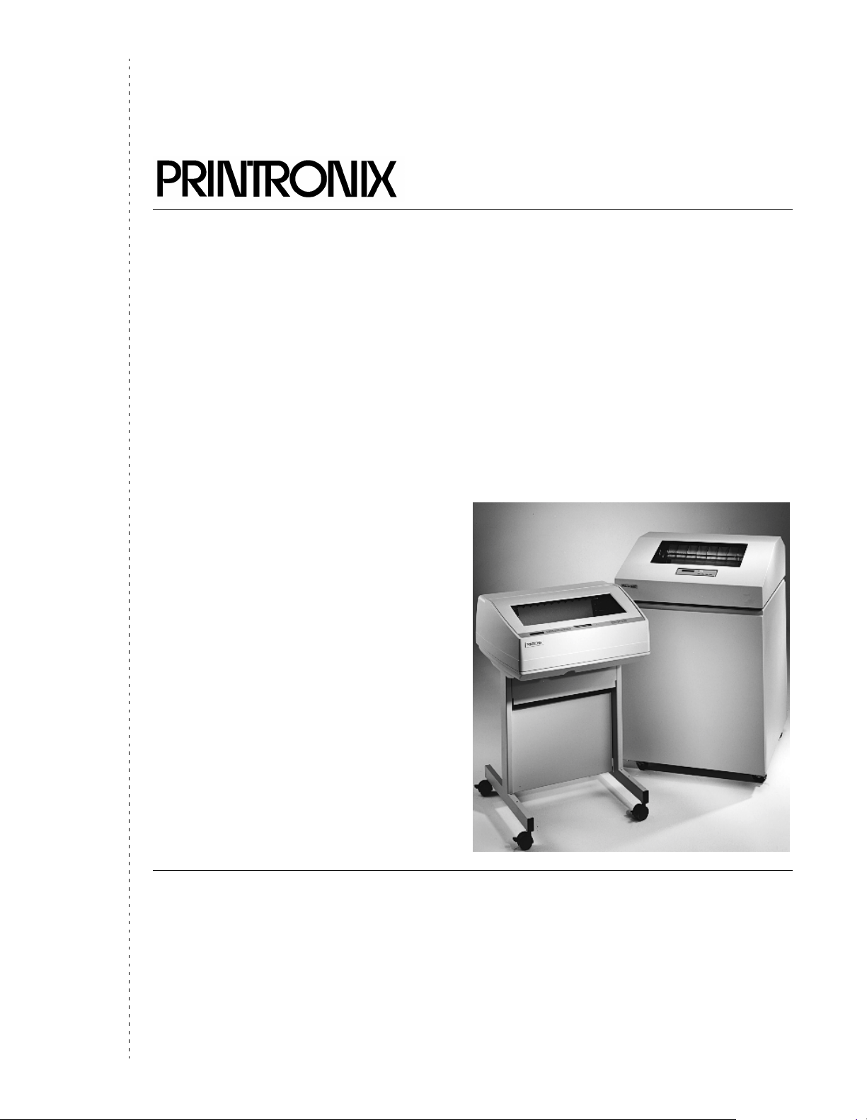
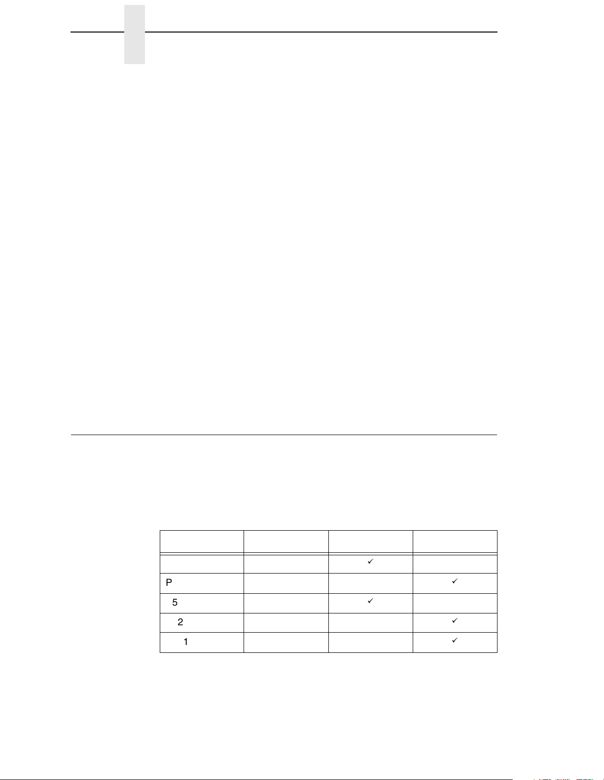
The P5000 series with DEC LG Emulation Printer Family
The DEC LG Emulation printers are a family of line matrix printers consisting
of 500, 1000, and 1500 line per minute (lpm) models packaged in various
configurations. All of the models offer software versatility and the latest
refinements in line matrix printing technology. The model numbers indicate
printing speed and physical configuration:
®
10
Table 1. The DEC LG Emulation
Model Number Print Speed Pedestal Cabinet
P5005 500 lpm
P5205 500 lpm
P5010 1000 lpm
P5210 1000 lpm
P5215 1500 lpm
á
á
á
á
á
Page 11

Printer Emulations
Most line matrix printers have specialized architectures, which enable the
printer to emulate, or behave like, another printer. These specialized
architectures are restricted. Your printer, however, introduces an open
architecture concept that is not available on any other line matrix printer.
Your printer is very easy to use. The message display and lights on the
control panel communicate with you directly and clearly. You can select every
function on your printer at the control panel, or you can send commands from
the host computer.
The printer has a feature called Flash memory, which allows you to download
programs from a diskette to your printer. Flash memory provides “instant”
booting of the printer. The absence of Read Only Memory (ROM) and the
flexibility of Flash memory makes program updates easy and eliminates the
need to swap parts to accommodate program changes.
The print mechanisms are housed in sound-insulation which make your
printer among the quietest impact printers in the world.
Printer Emulations
The following printer emulations (or protocols) are selectable at the control
panel:
• Digital LG
• LinePrinter Plus, which consists of:
®
IBM
Proprinter® III XL
®
Epson
Printronix P-Series
FX-1050
• IGP/PGL (optional)
• IGP/VGL (optional)
Each emulation provides a different set of configuration menus, control codes,
and character sets.
Host Computer Interfaces
The following host computer interface choices are available:
• Centronics
• IEEE
• Dataproducts
• RS-232 serial interface
• RS-422 serial interface
®
parallel interface
®
1284 parallel interface
®
parallel interface
11
Page 12
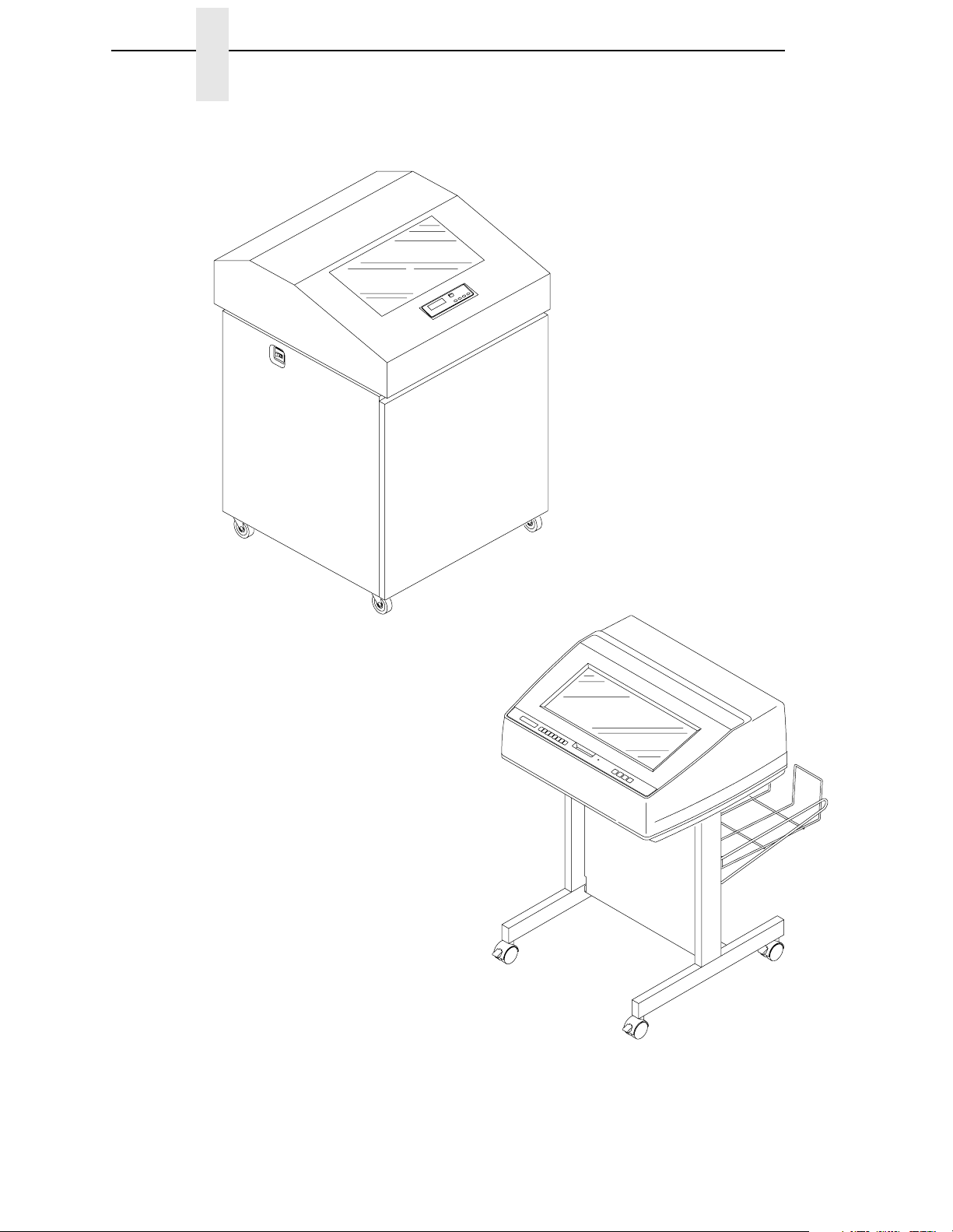
Chapter 1 The P5000 series with DEC LG Emulation
P5205
P5210
P5215
12
P5005
P5010
Figure 1. The DEC LG Emulation Printers
Page 13

Graphics Enhancement Option
Graphics Enhancement Option
The IGP/PGL and IGP/VGL emulations allow you to create and store forms,
generate logos, bar codes, expanded characters, and create other graphics.
Alphanumeric and bar code data are added as the form is printed.
These emulations are available as factory-installed or field-installed options.
For more information, contact your authorized service representative.
Taking Care of Your Printer
Your printer will produce high print quality jobs if it is well taken care of.
Periodic cleaning, handling the printer properly, and using the correct paper
and ribbons, will ensure optimum performance. Chapter 6 explains how to
clean the printer, and printer supplies are listed in Appendix A.
Whenever it is necessary to service the printer, remember these important
maintenance concepts:
• Use only the ribbons specified in Appendix A. Use of incorrect ribbons
can lead to ink migration problems, degraded print quality, and expensive
damage to the printer.
• Incorrect closure of the forms thickness lever can lead to smearing,
degraded print quality, paper jams, and damage to the platen and shuttle
assembly. Never close the forms thickness lever too tightly.
• Printing outside the boundaries of the paper will degrade print quality and
cause hammer bank damage. Never print outside of the paper width.
LinePrinter Plus Features
If you have enabled the LinePrinter Plus emulations, your printer will support
the following features:
Output Control
The printers have the following output control features:
• Three modes for printing text:
1) Correspondence (NLQ)
2) Data Processing (DP)
3) Draft (high speed)
• Selectable forms length and width
• Character attribute specification:
1) Selectable pitch: normal, expanded, and compressed
2) Bold (double-strike) printing
3) Emphasized (shadow) printing
4) Automatic underlining and overscoring
5) Superscript and subscript printing
6) Double high and wide printing
• Resident multinational character sets
13
Page 14

Chapter 1 The P5000 series with DEC LG Emulation
Graphics and Vertical Formatting
Several graphics and vertical formatting features are available:
• Four built-in graphics generators:
1) IBM Proprinter III XL bit-image graphics
2) Epson FX dot graphics mode
3) P-Series Plot
4) LG Sixel Graphics
• Programmable electronic vertical formatting provides rapid vertical paper
movement to specified lines for printing repetitive and continuous forms.
You can choose from the following methods:
1) Vertical tabbing in Proprinter III XL and Epson FX emulation modes
2) Electronic Vertical Format Unit (EVFU) in P-Series emulation mode
3) Centronics Vertical Format Unit (CVFU) in P-Series
4) Dataproducts Vertical Format Unit (DVFU) in P-Series
Built-in Diagnostic Tools
The following diagnostic tools are provided with the printer:
• Comprehensive diagnostic self-tests permanently stored in the printer
• Configuration printout
• Data stream hex code printout
Protocols and Emulations
A protocol is a set of rules governing the exchange of information between the
printer and its host computer. These rules consist of codes that manipulate
and print data and allow for machine-to-machine communication. A printer
and its host computer must use the same protocol. As used in this manual,
protocol and emulation mean the same thing.
Most impact printers use single ASCII character codes to print text, numbers,
and punctuation marks. Some characters, both singularly and in groups of two
or more, are defined as control codes. Control codes instruct the printer to
perform specific functions, such as underlining text, printing subscripts,
setting page margins, etc. The main difference between most printer
protocols is in the characters used to create control codes and the ways in
which these characters are formatted.
When the printer executes the character and control codes of a particular
printer protocol, it is “emulating” that printer. For example, if the printer uses
the Proprinter III XL protocol, it is emulating an IBM Proprinter III XL printer. If
the printer is using the Epson FX printer protocol, it is in Epson FX emulation
mode.
14
Page 15

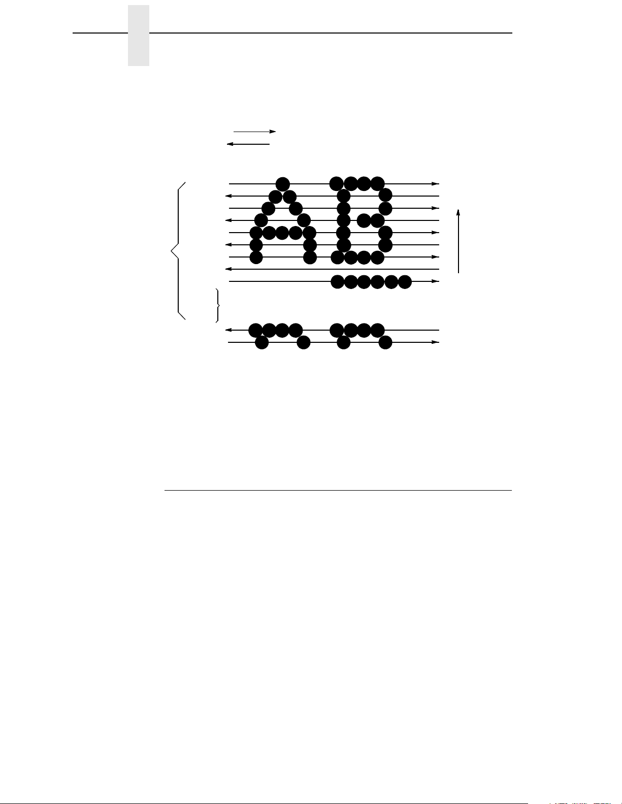
Line Matrix Printing
Line Matrix Printing
Your printer creates characters and graphics by a printing technique called
line matrix printing. Line matrix printing consists of printing patterns of ink dots
on paper, an entire line at a time.
Each text character is stored in memory as a pattern of dots on a logical grid
called the dot matrix. (See Figure 2.) The actual ink dots are made by a row of
hammer springs mounted on a shuttle that sweeps rapidly back and forth.
Printer logic divides every printable line into horizontal dot rows. The hammer
springs put dots at the required positions for the entire line by striking a
moving ink ribbon and the paper.
Dot Column
Matrix visible only to
the printer
Dot Row
Ink dots formed by
hammer tips
Character Column
Character Row
Figure 2. Dot Matrix Character Formation
Unlike serial dot matrix printers, which form complete text characters one at a
time with a moving printhead, a line matrix printer divides each printable line
into horizontal dot rows, then prints a dot row of the entire line with every
lateral sweep of the shuttle. (See Figure 3.)
During each sweep of the shuttle, the hammers print dots at the required
positions in the dot row. At the end of a sweep, the shuttle reverses direction,
the paper advances one dot row, and the hammers print the next row of dots
as the shuttle sweeps in the opposite direction.
15
Page 16
Chapter 1 The P5000 series with DEC LG Emulation
After a line of characters is printed, hammer action stops while the paper
advances to the first dot row of the next printable line. The number of rows
allowed for line separation depends on the line spacing you select.
Direction of Shuttle Movement
Dot
Row Start
1
2
3
4
10
11
5
6
7
8
*
9
**
Number of rows is determined by line spacing.
n
1
2
One
Text
Line
Paper
Feed
Direction
This row is used only for lowercase descenders.
*
This row is used for underlining and lowercase descenders.
**
Figure 3. Line Matrix Printing
Printing Speed
The speed at which text prints is measured in lines per minute (lpm). This
speed is inversely proportional to the number of dot rows required to produce
a character line, regardless of the number of characters in the line. More dot
rows are required to print lowercase characters with descenders;
consequently, those character lines print at a fractionally lower rate.
The printer also prints dot-addressable graphic images. The speed at which
graphics are plotted is measured in inches per minute (ipm). Unidirectional
plotting produces slightly better print quality and takes about twice as long as
bidirectional plotting. You can select either plotting mode from the control
panel.
Printing and plotting rates also vary according to the print mode you select.
Print mode refers to the way you instruct the printer to create characters. If,
for example, you select near letter quality (NLQ) mode, the printer uses more
dot rows to form characters than if you choose high speed (HS) mode.
Character formation and print speed are faster in HS mode because the
printer prints fewer dot rows to form characters. Vertical dot density is a factor
in printing speed.
16
Page 17

2 Setting Up the Printer
Before You Begin
Read this chapter carefully before installing and operating the DEC LG
Emulation printer.
The printer is easy to install, but for your safety, and to protect valuable
equipment, perform all the procedures in this chapter in the order presented.
Power Requirements
IMPORTANT
It is recommended that printer power be supplied from a separate AC
circuit protected at 10 amperes for 120 volts or 5 amperes for 230 volts
at 50 or 60 Hertz.
The printer must be connected to a power outlet that supplies 88 to 135 Volts
AC or 178 to 270 Volts AC at 47 to 63 Hz. The printer automatically senses
and adjusts itself to conform to the correct voltage range.
Primary circuit protection is provided by the power switch, which is also a
circuit breaker. Consult an electrician if printer operation affects local
electrical lines. See Appendix A for additional power specifications.
Select a Site
Printer dimensions are shown in Figure 4 and Figure 5. Select a printer site
that meets the following requirements:
• Permits complete opening of the printer cover and doors.
• Allows at least three feet of clearance behind the cabinet printer model.
(This permits air to circulate freely around the printer and provides access
to the paper stacking area.)
• Has a standard power outlet that supplies 100-120 Volts AC or 200-240
Volts AC power, at 47 to 63 Hz. The printer automatically senses and
adjusts itself to conform to the correct voltage range. (For the 100-120
Volt outlet, power may fluctuate between 88 and 135 Volts AC. For the
200-240 Volt outlet, power may fluctuate between 178 and 270 Volts.)
• Is relatively dust-free.
• Has a temperature range of 10° C to 40° C (50° F to 104° F), and a
relative humidity from 15% to 90% non-condensing.
17
Page 18
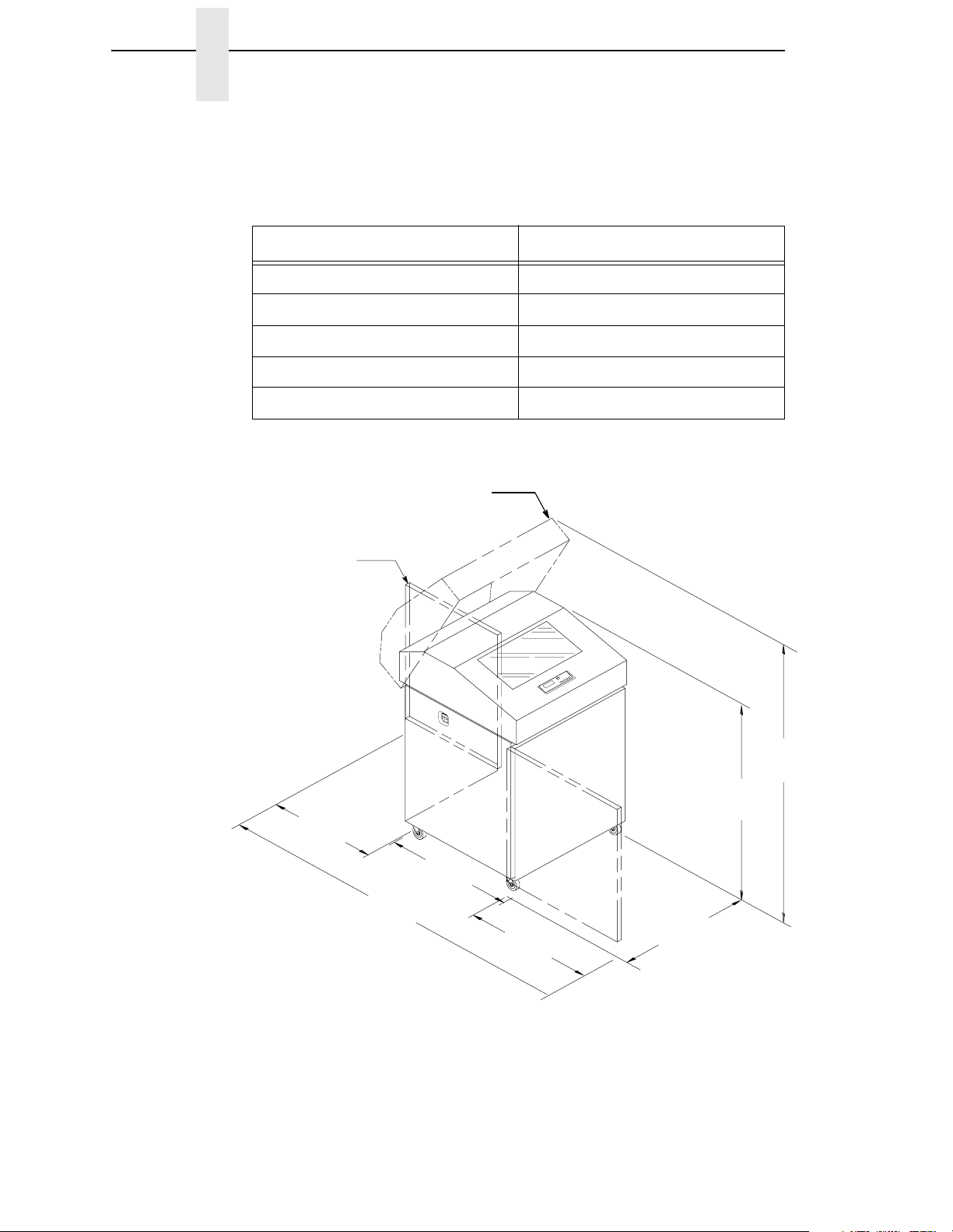
Chapter 2 Before You Begin
• Is located within the maximum allowable cable length to the host
computer. This distance depends on the type of interface you plan to use,
as shown in Table 2:
Interface Type Maximum Cable Length
Centronics Parallel 5 meters (15 feet)
IEEE 1284 Parallel 10 meters (32 feet)
Dataproducts Parallel 12 meters (40 feet)
Serial RS-232 15 meters (50 feet)
Serial RS-422 1220 meters (4000 feet)
Table 2. Interface Connections
Printer Cover
Cabinet Rear
Door
27.0 in.
(68.6 cm)
83.0 in.
(210.8 cm)
29.0 in.
(73.7 cm)
27.0 in.
27.0 in.
(68.6 cm)
(68.6 cm)
27.0 in.
(68.6 cm)
41.0 in.
(104.1 cm)
57.5 in.
(146.1 cm)
18
Figure 4. Cabinet Model Dimensions
Page 19
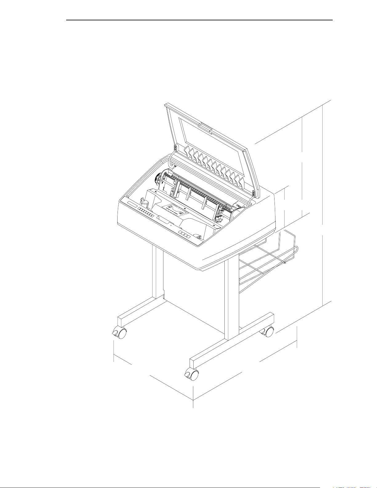
Select a Site
25 in.
(63.5 cm.)
24.6 in.
(62.48 cm.)
30 in.
(76.2 cm.)
10.5 in.
(26.67 cm.)
48.0 in.
(122 cm.)
Figure 5. Pedestal Model Dimensions
19
Page 20
Chapter 2 Before You Begin
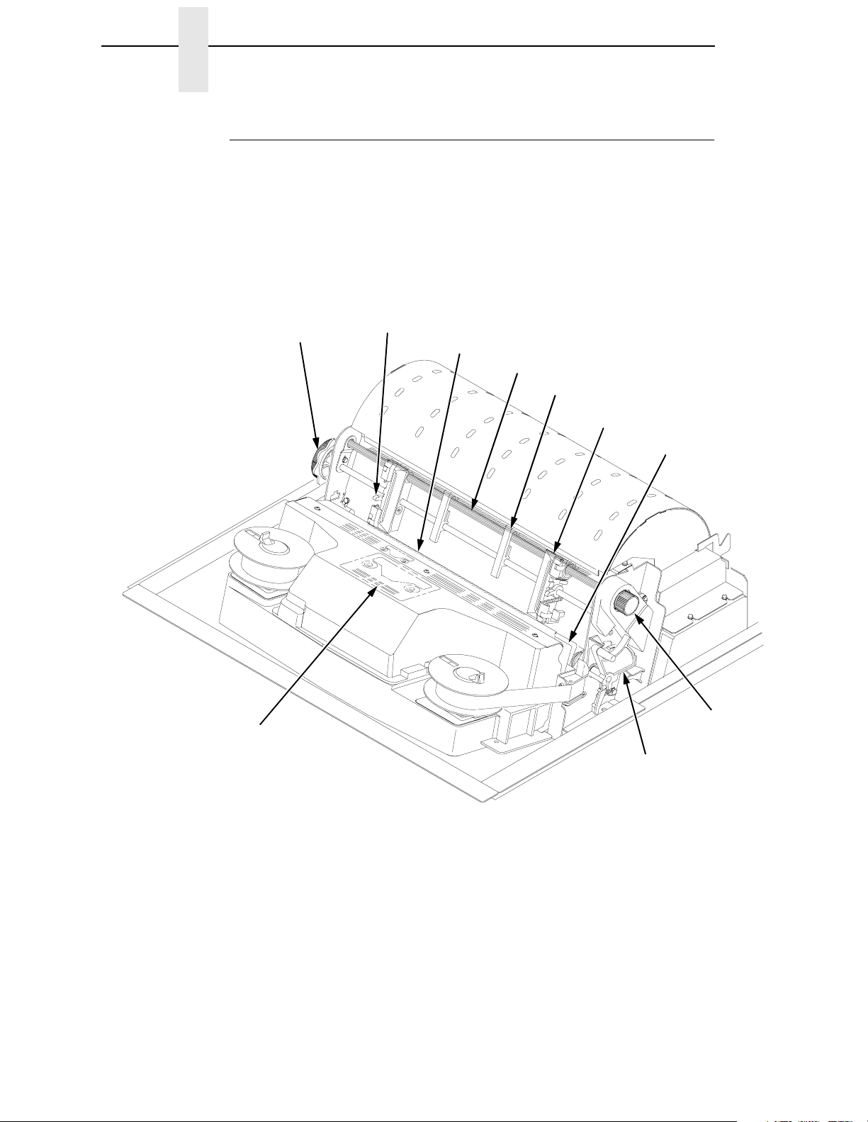
Printer Component Locations
Familiarize yourself with the names and locations of the printer components
shown in Figure 6 before continuing with the rest of the installation procedure.
Horizontal
Adjustment Knob
Ribbon Loading
Path Diagram
Tractor Lock
Paper Scale
Splined Shaft
Paper Support
Tractor
Hammer Bank Cover
and Ribbon Mask
Vertical Position
Knob
Forms Thickness
Lever
20
Figure 6. Component Locations
Page 21

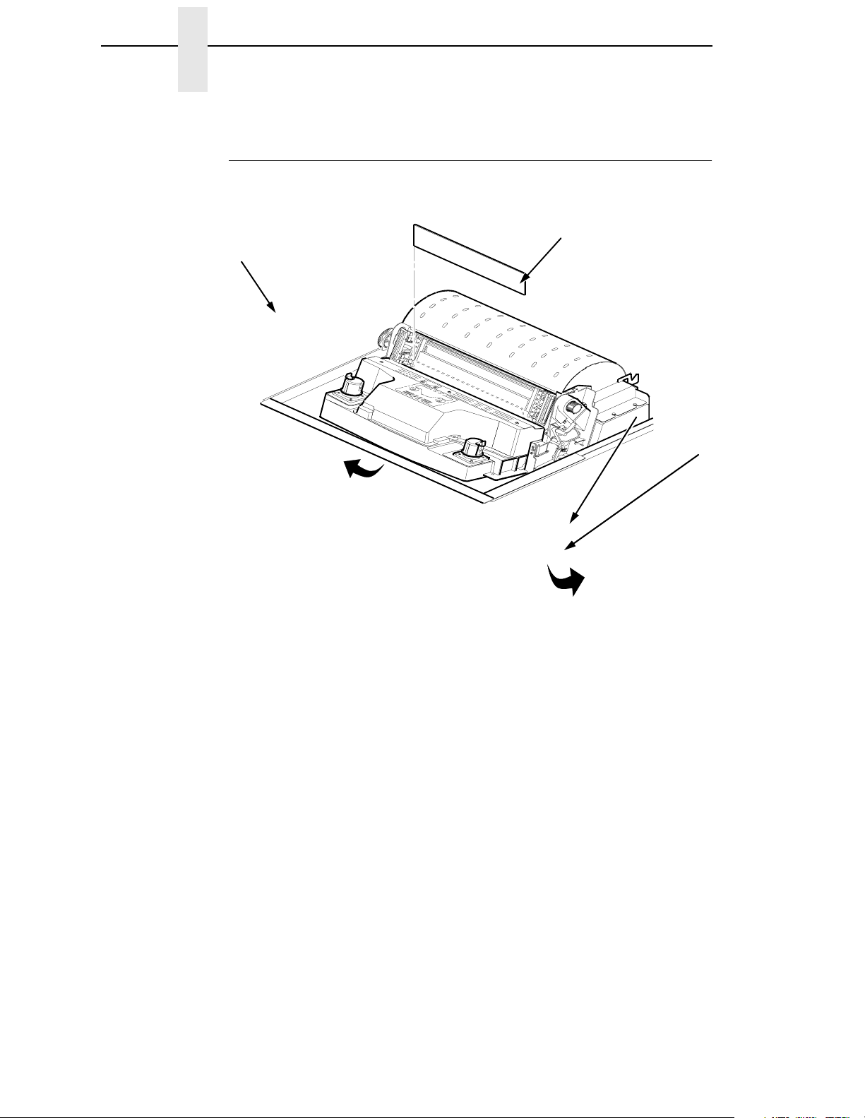
Remove the Cardboard Packing
Remove the Shipping Restraints (Cabinet Model)
Cardboard packing, protective foam, and tie wraps protect printer
mechanisms from damage during shipment. This section describes how to
remove these shipping restraints from the cabinet model before you operate
the printer.
Save the cardboard packing, foam blocks, and bubble wrap along with the
other packing materials, since you may need to reinstall them.
If it is necessary to move the printer, reinstall the shipping restraints. Reverse
the steps in this section.
CAUTION
Cardboard
Packing (2)
To avoid shipping damage, reinstall the shipping restraints whenever
you move or ship the printer.
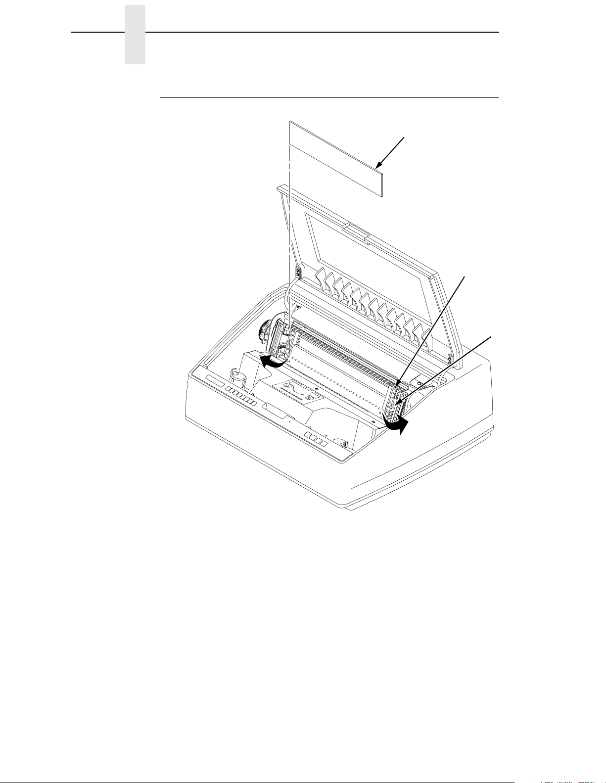
Remove the Cardboard Packing
55blocks
August 8, 2000
Figure 7. Removing the Cardboard Packing
1. Raise the printer cover.
2. Remove the cardboard packing.
3. Remove the envelope that contains the sample configuration printout.
Store this in the pouch that is attached to the left interior side of the
cabinet.
21
Page 22
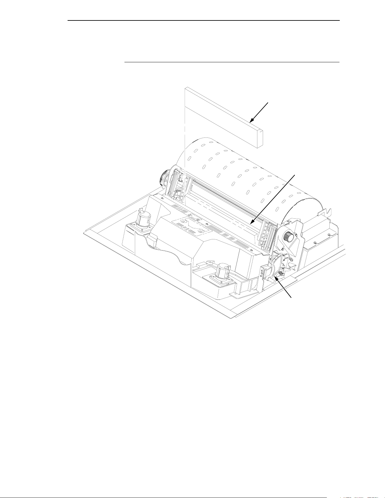
Chapter 2 Remove the Shipping Restraints (Cabinet Model)
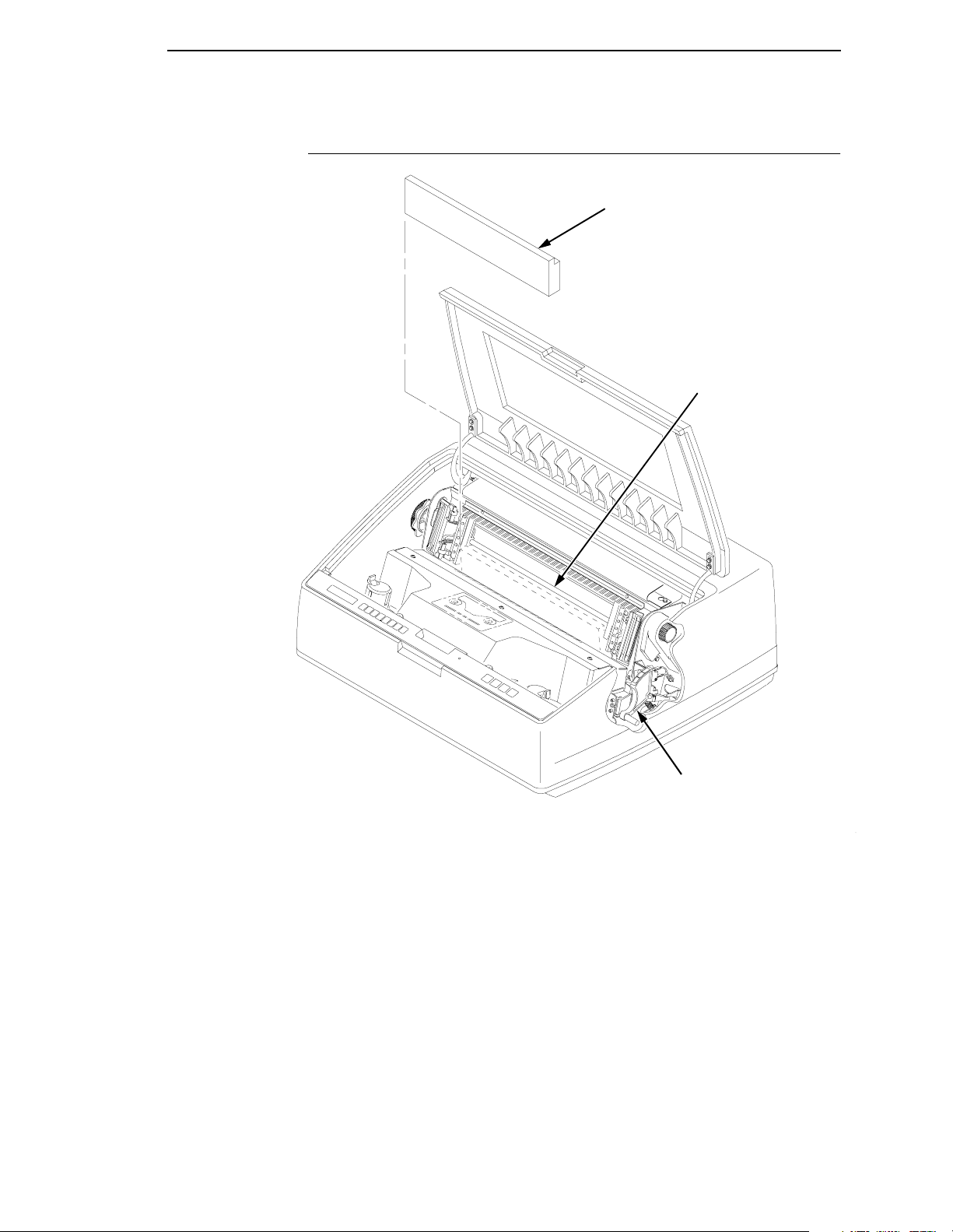
Remove the Hammer Bank Protective Foam and Foam Strips
Hammer Bank
Protective Foam
Foam Strips (2)
Tractor Door
Tractor Lock
22
Figure 8. Removing the Hammer Bank Protective Foam and Foam Strips
1. Open the tractor doors. Push the tractor locks down. Slide the tractors
and paper supports outward as far as they will go. The forms thickness
lever should be in the fully open (raised) position.
2. Lift the hammer bank protective foam and remove it from between the
ribbon mask and the platen.
3. Remove the foam strips and the tape securing the foam strips.
Page 23
Remove the Platen Protective Foam
Remove the Platen Protective Foam
Platen Protective Foam
Support Shaft
Forms Thickness Lever
Figure 9. Removing the Platen Protective Foam
1. Rotate the forms thickness lever downward to position “A”.
2. Rotate the platen protective foam toward the front of the printer and out
from under the support shaft. Remove the platen protective foam.
23
Page 24
Chapter 2 Remove the Shipping Restraints (Cabinet Model)
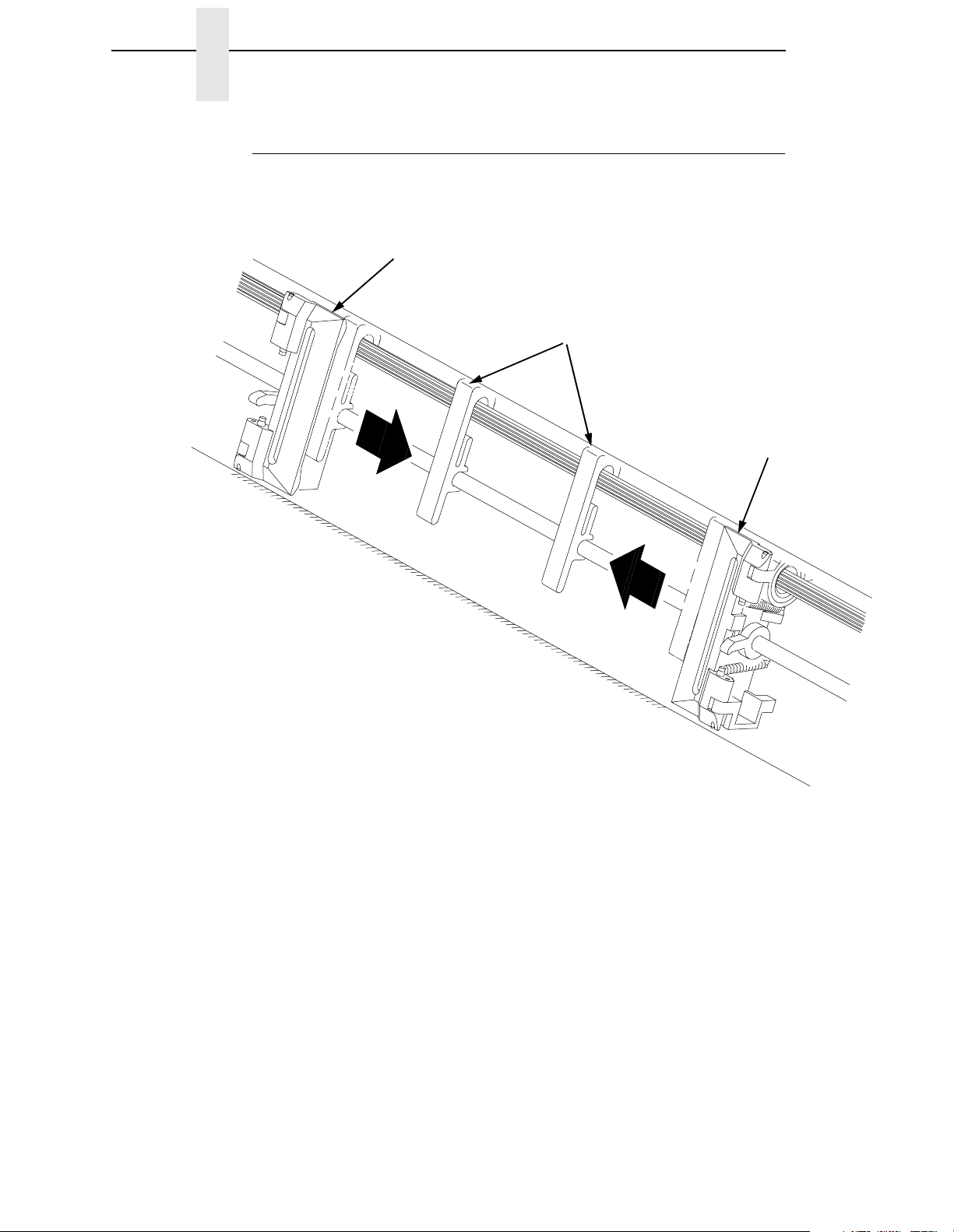
Adjust the Paper Supports
Tractor Door
Paper Supports
Tractor Door
24
Figure 10. Adjusting Paper Supports
1. Slide paper supports inward until they are approximately four inches from
the tractor door.
Page 25

Release the Paper Chains
Release the Paper Chains
Tie Wrap
Paper Chains
Tie Wrap
Plastic Bags
Figure 11. Releasing the Paper Chains
1. Open the cabinet rear door.
2. Cut the tie wraps and release the paper chains from the bags at the top
rear of the printer frame. Remove the tie wraps and bags.
3. Make sure each chain hangs freely, with no kinks or knots.
25
Page 26
Chapter 2 Remove the Shipping Restraints (Cabinet Model)
Remove the Tags
Tie Wrap
Passive Paper
Stacker
Tag
Figure 12. Remove Tag and Tie Wrap from Fence or Passive Paper
Stacker
1. Remove the tie wrap and large red tag attached to the passive paper
stacker.
2. Close the cabinet rear door.
3. Close the printer cover.
Tie Wrap
Tag
Fence
26
Page 27
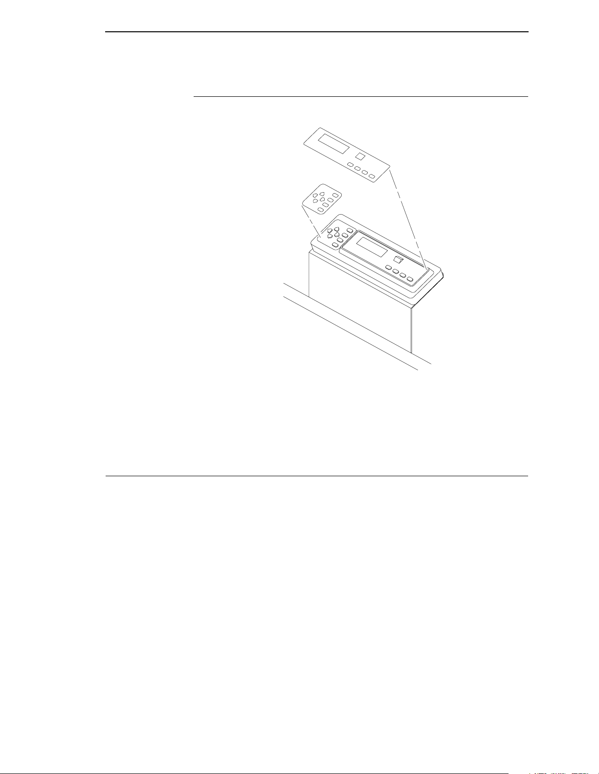
Attach the Control Panel Overlays
Attach the Control Panel Overlays
Figure 13. Attaching Control Panel Overlay
1. Choose the overlay labels in the appropriate language.
2. Open the printer cover, peel off the back of the overlay and apply to the
control panel.
Remove the Shipping Restraints (Pedestal Model)
Protective films and foam blocks protect printer mechanisms from damage
during shipment. This section describes how to remove these shipping
restraints from the pedestal model before you operate the printer.
Save the foam blocks, since you may need to reinstall them.
If it is necessary to move the printer, reinstall the shipping restraints. Reverse
the steps in this section.
CAUTION
To avoid shipping damage, reinstall the shipping restraints whenever
you move or ship the printer.
27
Page 28
Chapter 2 Remove the Shipping Restraints (Pedestal Model)
Remove the Hammer Bank Protective Foam
Hammer Bank
Protective Foam
Tractor Door
Tractor Lock
Figure 14. Removing the Hammer Bank Protective Foam
1. Raise the printer cover.
2. Open the tractor doors. Push the tractor locks down. Slide the tractors
and paper supports outward as far as they will go. The forms thickness
lever should be raised (in the fully open position).
3. Remove the envelope that contains the sample configuration printout.
28
4. Lift the hammer bank protective foam and remove it from between the
ribbon mask and the platen.
Page 29
Remove the Platen Protective Foam
Remove the Platen Protective Foam
Platen Protective
Foam
Support Shaft
Forms Thickness
Lever
Figure 15. Removing Platen Protective Foam
1. Rotate the forms thickness lever downward to position “A”.
2. Rotate the platen protective foam toward the front of the printer and out
from under the support shaft. Remove the platen protective foam.
29
Page 30

Chapter 2 Remove the Shipping Restraints (Pedestal Model)
Adjust the Paper Supports
Tractor Door
Paper Supports
Tractor Door
30
Figure 16. Adjusting Paper Supports
1. Slide paper supports inward until they are approximately four inches from
the tractor door.
2. Close the printer cover.
Page 31

Remove Tag
Remove Tag
Tie Wrap
Tag
Figure 17. Removing Tag from Cage
Remove the tie wrap attached to the wireform paper path. It is marked with a
large, red tag.
31
Page 32

Chapter 2 Remove the Shipping Restraints (Pedestal Model)
Attach the Output Basket
32
Figure 18. Attaching the Output Basket
1. Place the output basket in the holes in the back of the printer.
2. Screw the ground wire attached to the output basket to the printer.
Page 33

Attach the Control Panel Overlays
Attach the Control Panel Overlays
Figure 19. Attaching Control Panel Overlays
1. Choose the overlay labels in the appropriate language.
2. Open the printer cover and insert overlay labels by sliding them behind
the control panel assembly in the appropriate place.
33
Page 34

Chapter 2 Install Basic Components
Install Basic Components
The following section gives instructions on essential procedures which keep
your printer operational on a day-to-day basis.
Connect the Interface and Power Cables
Before you connect the interface and power cables, verify the voltage source
at the printer site conforms to the requirements specified on page 17. Make
sure the printer power switch is set to OFF (see Figure 21).
WARNING
WARNUNG
ATTENTION
Dataproducts
Parallel
To prevent serious personal injury from electrical shock when
connecting or disconnecting the host interface (signal) cable, make sure
that the printer is powered off and the power cable is unplugged.
Um ernstliche körperliche Verletzungen durch Stromschlag beim
Anschließen oder Trennen des Signalton-Kabels zu vermeiden, muß der
Drucker auf jeden Fall ausgeschaltet und der Netzstecker
herausgezogen werden.
Afin d'éviter tout risque de blessure par électrocution lors du
branchement ou du débranchement du câble de signal, mettre
l'imprimante hors tension et débrancher le câble d'alimentation.
Pedestal Model Cabinet Model
Centronics/IEEE
Parallel
Dataproducts
Diagnostic
Parallel
34
RS-232/RS-422
Serial
Figure 20. Cable Connection Locations
Diagnostic
Centronics/IEEE
Parallel
RS-232/RS-422
Serial
Page 35

I/O Cover
Connect the Interface and Power Cables
Cabinet Model Pedestal Model
Host Interface
Connectors
OFF/ON
Host Interface
Connectors
AC Power
Connector
Power Switch
Cable-Routing
Notch (2)
AC Power Cable
AC Power Connector
Figure 21. Interface and Power Locations
1. Make sure the printer power switch is set to OFF (see Figure 21).
Connect the (customer-supplied) interface cable from the host computer
to the appropriate printer interface connector (see Figure 20). Refer to
Chapter 5, “Interfaces,” for descriptions of the connectors and their pin
assignments.
a. Remove the cover from the interface connector you have selected.
b. Hold the interface cable below its connector, and gently attach the
cable connector to the printer interface connector.
2. Plug the power cord into the printer AC power connector, then into the AC
power outlet (see Figure 21).
35
Page 36

Chapter 2 Install Basic Components
Install the Ribbon
Figure 22. Ribbon Path Diagram Location
1. Refer to the ribbon path diagram molded onto the shuttle cover.
36
55cabopn
MAy 1, 2001
Figure 23. Opening the Printer Cover
2. Verify that the printer is offline and that the printer cover is open.
Page 37

Tractor Door
Forms Thickness Lever
Install the Ribbon
Figure 24. Forms Thickness Lever
3. Raise the forms thickness lever as far as it will go.
4. Swing open the tractor doors.
Hub Latch
Figure 25. Right Hub Latch
5. Squeeze the right hub latch and place the full spool on the right hub. Be
sure the ribbon feeds off the outside of the spool. Press the spool down
until the hub latch snaps into place.
37
Page 38

Chapter 2 Install Basic Components
Paper
Hammer Bank Cover
Ribbon Mask
55rib2a
April 27, 2001
Ribbon Guide
Ribbon Mask
Hammer Bank Cover
Platen
Ribbon
Front of
Printer
Hammer Tip
CAUTION
38
Figure 26. Ribbon Path
6. Thread the ribbon around the ribbon guide and along the ribbon path.
Refer to the ribbon path diagram on the shuttle cover. Be sure to thread
the ribbon between the hammer bank cover and the ribbon mask.
The ribbon must not be twisted. A twisted ribbon can lower print quality,
shorten ribbon life, and cause paper jams.
Page 39

Cabinet Model
Install the Ribbon
55rib3
August 15, 2000
Pedestal Model
p55rib3
May 1, 2001
Figure 27. Left Ribbon Hub
7. Place the empty spool on the left hub. Press the spool down until the hub
latch snaps into place. Turn the spool by hand to make sure the ribbon
tracks correctly in the ribbon path and ribbon guides.
39
Page 40

Chapter 2 Install Basic Components
Load the Paper
This section explains how to load paper for the first time. If you are loading
paper over existing paper, see the Operator’s Guide.
Tractor Door
Forms Thickness Lever
Figure 28. Forms Thickness Lever and Tractor Doors
When you start this procedure, verify that the printer cover is open, the forms
thickness lever is raised, and the tractor doors are open.
EDGE
OF
PAPER
BOX
Figure 29. Paper Supply Label Location
1. On cabinet models, open the front door. Align the paper supply with the
label on the floor. Ensure that the paper pulls freely from the box.
40
Page 41

Paper Slot is 8 inches
below printer base
Load the Paper
Paper Slot
Figure 30. Paper Slot Location
2. Feed the paper up through the paper slot. Hold the paper in place with
one hand (to prevent it from slipping down through the paper slot) while
pulling it through from above with your other hand.
Tractor Door
Paper
Tractor Lock
Ribbon Path Diagram
Figure 31. Loading Paper Onto the Left Tractor Sprockets
3. Pull the paper above and behind the ribbon mask, which is a silver metal
strip with a clear plastic edge protector. Refer to the ribbon path diagram
on the shuttle cover. Load the paper on the left tractor sprockets and
close the tractor door. Normally, you should not need to adjust the
position of the left tractor.
41
Page 42

Chapter 2 Install Basic Components
4. If adjustment is necessary, unlock the left tractor. Slide the tractor until it
is directly to the left of the number “1” on the paper scale and lock it. (You
can also use the paper scale to count columns.)
Paper Scale
Figure 32. Paper Scale
CAUTION
To avoid damage to the printer caused by printing on the platen, always
position the left tractor unit directly to the left of the “1” mark on the
paper scale.
Splined Shaft
Figure 33. Loading Paper Onto the Right Tractor Sprockets
5. Unlock the right tractor.
6. Load the paper onto the sprockets and close the tractor door. Make sure
the leading edge of the first sheet of paper is perfectly parallel to the
tractor splined shaft (paper is not crooked). If paper is crooked, reload it
onto the tractor sprockets until its edge is parallel to the splined shaft.
42
7. Slide the right tractor to remove paper slack or to adjust for various paper
widths. Then lock the tractor.
Page 43

Load the Paper
Horizontal
Adjustment
Knob
Figure 34. Horizontal Adjustment Knob
8. After both tractors are secured, you may use the horizontal adjustment
knob to make fine horizontal paper adjustments.
Thin Paper
A
Medium Paper
B
Thick Paper
C
Figure 35. Lowering the Forms Thickness Lever
9. Lower the forms thickness lever. Set it to match the paper thickness.
The A-B-C scale corresponds approximately to 1-, 3-, and 6-part paper
thickness. Adjust until you have the desired print quality.
NOTE: Do not set the forms thickness lever too tightly; excessive friction can
cause paper jams, ribbon jams with potential for ribbon damage,
smeared ink, or wavy print.
10. For cabinet models, close the cabinet front door.
11. Continue on to the next section to power on the printer.
43
Page 44

Chapter 2 Install Basic Components
Power On the Printer
Following are instructions for powering on the printer after you have installed
the ribbon and loaded paper.
Figure 36. The Power Switch
1. When you start this procedure, verify that paper and ribbon are installed,
the forms thickness lever is lowered, and the tractor doors are closed.
This prevents a “LOAD PAPER” or “CLOSE PLATEN” error message
from displaying after the printer is powered on.
2. Set the power switch to the ON position (Figure 36). The printer initializes
and runs several self-tests. The messages “TESTING HARDWARE /
PLEASE WAIT” and “DIAGNOSTICS / PASSED” will each display briefly.
When the self-tests complete and the software has initialized
successfully, the message “ONLINE / LG” appears on the message
display.
If the status indicator flashes and a fault message displays, this indicates
a fault condition; refer to the fault messages section in Chapter 6,
“Routine Service and Diagnostics.”
44
Page 45

Set the Top-of-Form
Set the Top-of-Form
Following are instructions for setting the top-of-form after you have powered
on the printer.
Paper Path
Figure 37. The Lower Paper Guide
1. When you start this procedure, verify that the printer is in offline mode,
with the printer cover open and the forms thickness lever lowered.
2. Press the FF key several times to ensure the paper feeds properly
beyond the tractors and over the lower paper path. Ensure the paper folds
in the same way in the stacking area as it does in the supply area.
45
Page 46

Chapter 2 Install Basic Components
Figure 38. Raising the Forms Thickness Lever
3. Raise the forms thickness lever as far as it will go. This allows you to turn
the vertical position knob freely in order to align the top-of-form.
Forms Thickness
Lever
TOF Indicator
Perforation
Vertical Position
Knob
Figure 39. Aligning the Top-of-Form
4. Locate the TOF indicator. It is the small tab located on the tractor doors.
5. Turn the vertical position knob to align the top of the first print line with the
TOF indicator.
46
Page 47

Thin Paper
A
Medium Paper
B
Thick Paper
C
Set the Top-of-Form
IMPORTANT
Figure 40. Lowering the Forms Thickness Lever
6. Lower the forms thickness lever. Set it to match the paper thickness.
The A-B-C scale corresponds approximately to 1-, 3-, and 6-part paper
thickness. Adjust until you have the desired print quality.
NOTE: Do not set the forms thickness lever too tightly; excessive friction can
cause paper jams, ribbon jams with potential for ribbon damage,
smeared ink, or wavy print.
The forms thickness lever must be closed; otherwise, there will be no
paper movement when you press SET TOF.
7. Press SET TOF. The top-of-form position that you have set moves down
to the print position.
8. Go on to the next procedure to run a simple printer test.
47
Page 48

Chapter 2 Install Basic Components
ONLINE
+
UNTIL
R/S
R/S
+
CLEAR
Test the Printer
Table 3. Printer Test Procedure
Step Key Result Notes
1. Make sure that the printer top cover is open and the forms thickness lever is lowered.
2. The printer must be off line for
3. Allows you to make configuration
4.
5.
6.
7. The printer outputs a sliding
8. Stops test.
OFFLINE
CONFIG. CONTROL
ENTER SWITCH
UNLOCKED
OFFLINE
CONFIG. CONTROL
OFFLINE
DIAGNOSTICS
DIAGNOSTICS
Printer Tests
Printer Tests
Shift Recycle*
Printer Tests
Shift Recycle*
Printer Tests
Shift Recycle*
testing.
changes.
alphabet pattern.
9. Locks the configuration
10. Moves the printer out of the
ENTER SWITCH
LOCKED
OFFLINE
CONFIG. CONTROL
parameters.
menus to offline.
11. Examine the print quality. The characters should be fully formed and of uniform
density. If the test does not run or characters appear malformed, contact your
authorized customer service engineer.
12. If the print quality is good, close the printer cover; press ONLINE to enable printing. To
select an emulation and configure the printer with the control panel, go to Chapter 3.
48
Page 49

3 Configuring the Printer
Overview
IMPORTANT
Configuration directly affects printer operation. Do not change the
configuration of your printer until you are thoroughly familiar with the
procedures in this chapter.
In order to print data, the printer must respond correctly to signals and
commands received from the host computer. Configuration is the process of
matching the printer operating characteristics to those of the host computer
and to specific tasks, such as printing labels, or printing on different sizes of
paper. The characteristics that define the printer’s response to signals and
commands received from the host computer are called configuration
parameters.
You can configure the printer using the configuration menus and the control
panel, or by sending control codes in the data stream from a host computer
attached to the printer.
This chapter provides a tutorial introduction. Figure 41 shows an overview of
the configuration menus.
Following the menu is background information on topics such as changing
and saving parameters, custom configurations, and operating modes. Several
step-by-step procedures are also provided that show how to change
configuration parameters and how to save, print, and load configurations from
printer memory. For details on the entire set of configuration menu options,
see Chapter 4.
The host control codes for each emulation are described in their
corresponding Programmer’s Reference Manual. See “Related Documents”
on page 9 for more information.
49
Page 50

Chapter 3 Overview
OFFLINE
CONFIG.
CONTROL
Load Config.
Save Config.
Print Config.
Delete Config.
Power-Up Config.
Protect Configs.
PRINTER
CONTROL
Unidirectional
PMD Fault
Slow Paper Slew
Power Saver Time
ACTIVE
EMULATION
LG*
LinePrinter+
IGP/PGL & LP+
IGP/VGL & LP+
DIAGNOS-
TICS
Printer Tests
Test Width
Paper Out Dots
System Memory
Print Statistics
1
EMULATION MAINT/MISC
LG*
LinePrinter+
IGP/PGL & LP+
IGP/VGL & LP+
RIBBON
MINDER
New Ribbon
Ribbon Action
Ribbon Size
Ribbon Adjust
Fault Action
Hex Dump Mode
Power-Up State
Display Language
HOST
INTERFACE
Serial*
Parallel
Centronics
Dataproducts
Bidirectional
1
Choices available are limited to the emulations
configured with the printer.
Figure 41. Configuration Menu Overview
50
To view options, press: ⇓ Down
⇑ Up
⇒ Next
⇐ Prev
To select an option, press ENTER.
To return to main menu, press
CLEAR.
To exit menu, press ONLINE.
* = Default Setting
Page 51

Changing and Saving Parameter Settings
Changing and Saving Parameter Settings
You can change a parameter setting, such as line spacing or forms length, by
pressing keys on the control panel or by sending emulation control codes in
the host data stream. Refer to the appropriate Programmer’s Reference
Manual for information about control codes.
When you change a parameter, it is active as long as the printer is on or until
changed. This is true whether you used the control panel or sent a control
code from the host.
If you use the control panel, you can save the parameters as a customized
configuration. A configuration consists of a group of parameters. A saved
configuration will not be lost if you turn off the printer although the printer will
not power up in this configuration unless saved as the power-up configuration.
You can change a parameter with a control code, but to save the parameter
setting you must use the control panel.
Control codes override control panel parameters. For example, if you set the
line spacing to 6 lpi with the control panel, and application software later
changed this to 8 lpi with a control code, the control code setting overrides the
control panel setting.
The 8 lpi parameter is effective as long as the printer is on or until changed. If
you turn off the printer, the 8 lpi parameter will be erased. To save the
parameter, you must use the control panel and save it as a configuration.
Default and Custom Configurations
A configuration consists of a group of parameter settings, such as line
spacing, forms length, etc. Your printer provides a fixed default configuration
and also allows you to define several custom configurations for use with
particular print jobs.
• The factory default configuration (configuration 0) can be loaded, but it
cannot be altered. See page 53 for a list of all the factory default
parameter values.
• Eight configurations can be modified for unique print job requirements.
The “Save Config.” option allows you to save eight groups of parameter
settings in non-volatile memory as custom configurations numbered from
1 through 8. See page 57 for an explanation of how to save a set of
parameter values as a custom configuration using the “Save Config.”
menu option.
51
Page 52

Chapter 3 Overview
Operating Modes
The printer has three operating modes: online mode, offline mode, and fault
mode.
• Online Mode. When the printer is online, it is controlled by the host
computer and prints data sent by the host computer.
• Offline Mode. In offline mode, communication with the host is interrupted
so that you can load paper, change ribbons, or test and configure the
printer.
• Fault Mode. When the printer is in fault mode, it has encountered an
error condition, and printing stops until the error condition is cleared.
The Control Panels
UP
DOWN
CLEAR
NEXTPREV
R/S
SET TOF
ENTER
ON LINE FF VIEWLF
Figure 42. The Cabinet Control Panel
R/S
SET
TOF
ENTER
ON LINE
FF
DOWNUP
CLEAR
NEXTPREV
Figure 43. The Pedestal Control Panel
When you are navigating within the configuration menus (in offline mode),
several of the control panel keys have specialized functions. They are
described in the Operator’s Guide.
LF
VIEW
52
Page 53

Unlocking and Locking the ENTER Key
Unlocking and Locking the ENTER Key
The ENTER key is locked by default, to prevent you from accidentally
changing the printer configuration. You should generally unlock the ENTER
key directly before you begin configuration using the menus; once the
changes are made, relock the ENTER key to secure your new settings.
To unlock the ENTER key, place the printer in the offline mode and press UP
and DOWN simultaneously. The following message will display briefly:
ENTER SWITCH
UNLOCKED
To lock the ENTER key, place the printer in offline mode and press UP and
DOWN simultaneously. The following message will display briefly:
ENTER SWITCH
LOCKED
Factory Default Configuration Values
The factory default values are permanently stored in memory as a
configuration. They cannot be modified or erased.
EMULATION LG
LG
Font
StyleDP 10 6
Character SetUS ASCII
Vert. Forms
Bot Frm66/6
Top Mrg0/6
Horiz. Forms
Left Mrg00.0
Right Mrg13.6
AutowrapNo
CR=CR
LF=LF
Unsolicited RptNo
Print Mode OptEnable
Plot Mode OptEnable
I-2/5 Guard BarsEnable
LinePrinter+
Printer Protocol
Proprinter
Define CR codeCR=CR
Auto LFEnable
Define LF codeLF = LF
FF Valid at TOFEnable
Character SetCode Page 437
Alt Char SetSet 1
20 CPI CondensedEnable
CPI/LPI Select
Select CPI10.0 CPI
Select LPI6.0 LPI
Font Attributes
TypefaceData Processing
Prop. SpacingDisable
Bold PrintDisable
53
Page 54

Chapter 3 Overview
Italic PrintDisable
Slashed ZeroDisable
Page Format
Margins
Left Margin0 columns
Right Margin0 columns
Bottom Margin0 lines
Perforation SkipDisable
Form Length
Abs. Length IN11.0 inches
Abs. Length MM279.4 mm
Function of lines66 lines
Form Width
Abs. Width IN13.6 inches
Abs. Width MM345.4 mm
Function of CPI136 characters
MAINT / MISC
Hex Dump ModeDisable
Power-up StateOnline
Display LanguageEnglish
HOST INTERFACE
Serial
Interface TypeRS-232
Data ProtocolXON/XOFF
Baud Rate9600 Baud
Word Length8
Stop Bits1
ParityNone
Data Term ReadyTrue
Request to SendTrue
Buffer Size8 Kbyte
PRINTER CONTROL
UnidirectionalDisable
PMD FaultEnable
Slow Paper SlewDisable
Power Saver Time15 min.
DIAGNOSTICS
Printer TestsShift Recycle
Test WidthFull Width
Paper Out Dots40 dots
RIBBONMINDER
Ribbon ActionDisable
Ribbon Size100 Yards
1
Ribbon Adjust0
Fault ActionNew Ribbon
1
Default is 60 yards for pedestal models
54
Page 55

Changing Parameters
ONLINE
+
A configuration consists of several parameters. The default factory
configuration has a starting set of parameters. Your print jobs may require
different parameter settings from the default that is provided. This section
provides an example procedure for changing and saving individual parameter
values.
Example
The following procedure shows how to change and save the settings for the
Unidirectional option. Use these basic guidelines to navigate the configuration
menus and change other parameters.
If you think the configuration for your printer has already been changed from
the default, you should load the default configuration before starting this
procedure (page 63).
Example
OFFLINE
CONFIG.
CONTROL
. . .
PRINTER
CONTROL
Unidirectional
Disable*
Enable
PMD Fault
Enable*
Disable
Slow Paper
Slew
Disable*
Enable
Power Saver
15* - 60 Min.
Instant
NOTE: Once you change active emulations, any changes to the previously
selected emulation will be gone unless they have been saved.
Table 4. Parameter Change Example Procedure
Step Key Result Notes
1. Make sure the printer is on. Raise the printer cover.
* = Factory Default
Time
2.
3. Allows you to make configuration
OFFLINE
CONFIG. CONTROL
ENTER SWITCH
UNLOCKED
OFFLINE
CONFIG. CONTROL
changes.
55
Page 56

Chapter 3 Changing Parameters
UNTIL
OR
ENTER
UNTIL
UNTIL
+
ONLINE
Table 4. Parameter Change Example Procedure (continued)
Step Key Result Notes
4.
5.
6.
7. Cycle through the choices.
8. An asterisk (*) indicates this
OFFLINE
PRINTER CONTROL
PRINTER CONTROL
Unidirectional
Unidirectional
Disable*
Unidirectional
Enable
Unidirectional
Enable*
choice is active.
TO SAVE YOUR CHANGES AS A CONFIGURATION THAT IS STORED IN MEMORY:
1.
2.
OFFLINE
PRINTER CONTROL
OFFLINE
CONFIG. CONTROL
3. Go to the CONFIG. CONTROL submenu Save Config. option, as described on page
58, step 4.
TO USE THE CURRENT CONFIGURATION WITHOUT SAVING:
1.
2.
ENTER SWITCH
LOCKED
ONLINE
3. On cabinet models, close the printer cover. The printer is ready for operation. All
parameters are effective as long as the printer is on. When you turn off the printer, the
parameters will be erased from memory.
56
Page 57

CONFIG.
CONTROL
Saving Your New Configuration
Saving Your New Configuration
* = Factory Default
Load Config.
Save Config. Print Config.
1
2
3
4
5
6
7
8
Delete Config.
Power-Up
Config.
Protect
Configs.
After changing all of the necessary parameters, it is recommended you save
them as a configuration that can be stored and loaded later for future use. If
you do not save your configuration before you power off the printer, all of your
parameter changes will be erased. The Save Config. option allows you to
save up to eight configurations to meet different print job requirements.
Configurations 1 through 8 are empty until you save values to them using the
Save Config. option. For example:
Config 1: Selects DP typeface, 10 cpi, 6 lpi
Config 2: Selects NLQ typeface, 12 cpi, 8 lpi
Once you have saved a configuration using this option, it will not be lost if you
power off the printer. You can load a configuration for a specific print job
(page 63). You can also modify and resave it. You may want to print your
configurations and store them in a safe place, such as inside the printer
cabinet.
NOTE: The Protect Configs. parameter must be set to disable before you
may save a configuration. Once you save a configuration, the Protect
Configs. parameter automatically returns to enable. Once you change
active emulations, any changes to the previously selected emulation
will be gone unless they have been saved.
57
Page 58

Chapter 3 Changing Parameters
ONLINE
+
UNTIL
OR
ENTER
UNTIL
+
ONLINE
Table 5. Saving Configurations
Step Key Result Notes
1. If you are already in the configuration menu, go to step 5.
2.
3. Allows you to make configuration
4.
5.
6.
7. Press until the desired number
OFFLINE
CONFIG. CONTROL
ENTER SWITCH
UNLOCKED
OFFLINE
CONFIG. CONTROL
CONFIG. CONTROL
Load Config.
CONFIG. CONTROL
Save Config.
Save Config.
1*
Save Config.
2
changes.
(1-8) displays.
NOTE: Do not turn off the printer while save is in progress because you might lose your
configuration.
8. The configuration is now saved in
9.
Save Config.
2*
CONFIG. CONTROL
Save Config.
memory. (In this case, config. 2.)
NOTE: It is recommended you print the configuration. Go to page 62, step 5. If you decide not
to print the configuration, then continue with the following steps.
10. Locks the ENTER key.
11.
ENTER SWITCH
LOCKED
ONLINE
12. Close the printer cover. The printer is ready for operation.
58
Page 59

CONFIG.
CONTROL
Deleting Your Configuration
Deleting Your Configuration
* = Factory Default
Load Config.
Save Config. Print Config.
Delete Config.
1*
2
3
4
5
6
7
8
Power-Up
Config.
Protect
Configs.
If you wish to delete a configuration from memory, select the appropriate
configuration number from the menu and press ENTER.
The Protect Configs. parameter must be set to disable before you may delete
a configuration. Once you delete a configuration the Protect Configs.
parameter automatically returns to enable.
59
Page 60

Chapter 3 Changing Parameters
ONLINE
+
UNTIL
OR
ENTER
+
ONLINE
Table 6. Deleting Configurations
Step Key Result Notes
1. Make sure the printer is on. Raise the printer cover.
2.
OFFLINE
CONFIG. CONTROL
3. Allows you to make configuration
ENTER SWITCH
UNLOCKED
changes.
OFFLINE
CONFIG. CONTROL
4.
CONFIG. CONTROL
Load Config.
5.
CONFIG. CONTROL
Delete Config.
6.
Delete Config.
1*
7. Press until the desired number
8. The printer has deleted the
Delete Config.
3
Deleting Configuration
(1-8) displays.
selected configuration.
Delete Config.
3*
9. Locks the ENTER key.
ENTER SWITCH
LOCKED
10.
ONLINE
11. Close the printer cover. The printer is ready for operation.
60
Page 61

CONFIG.
CONTROL
Protecting Your Configurations
Protecting Your Configurations
* = Factory Default
Load Config.
CONFIG.
CONTROL
Load Config.
Save Config. Print Config.
Delete Config.
Power-Up
Config.
Protect
Configs.
Enable*
Disable
In order to save or delete a configuration you must set the Protect Configs.
option to disable. The Protect Configs. selection will automatically return to
enable once a configuration is saved or deleted.
Printing the Current Configuration
* = Factory Default
Save Config.
Print Config. Delete Config.
Current*
Factory
Power-Up
All
1
2
3
4
5
6
7
8
Power-Up
Config.
Protect
Configs.
The configuration printout lists the stored parameters. You can print any or all
of the configurations shown above. Configurations 1-8 are customized
configurations.
To print a configuration, follow the procedure in Table 7.
61
Page 62

Chapter 3 Changing Parameters
ONLINE
+
UNTIL
OR
ENTER
+
ONLINE
Table 7. Printing Configurations
Step Key Result Notes
1. Make sure the printer is on. Raise the printer cover.
2.
3. Allows you to make configuration
4.
5.
6.
7. Press until the desired option
8. The configuration listing begins
OFFLINE
CONFIG. CONTROL
ENTER SWITCH
UNLOCKED
OFFLINE
CONFIG. CONTROL
CONFIG. CONTROL
Load Config.
CONFIG. CONTROL
Print Config.
Print Config.
Current*
Print Config.
All
OFFLINE
CONFIG. CONTROL
changes.
displays.
printing.
9. Carefully tear off the configuration printout.
10. Locks the ENTER key.
11.
ENTER SWITCH
LOCKED
ONLINE
12. Close the printer cover. Store the printout in a safe place. The printer is ready for
operation.
62
Page 63

CONFIG.
CONTROL
Loading Configuration Values
Loading Configuration Values
* = Factory Default
Load Config.
0*
1
2
3
4
5
6
7
8
Save Config. Print Config.
Delete Config.
Power-Up
Config.
Protect
Configs.
You can load any of the eight customized configurations or the factory default
configuration.
The loaded configuration remains active as long as the printer is on. If you
power off the printer, the power-up configuration will load.
“The Power-Up Configuration” on page 65 explains how to select the powerup configuration. If you do not set a power-up configuration, the factory
default configuration will load if you power the printer off and then back on.
NOTE: A configuration must be saved before you can load it.
63
Page 64

Chapter 3 Changing Parameters
ONLINE
+
OR
ENTER
+
ONLINE
Table 8. Loading Configurations
Step Key Result Notes
1. Make sure the printer is on. Raise the printer cover.
2.
3. Allows you to make configuration
4.
5.
6. Press until the desired number
7. Displays for about a second.
OFFLINE
CONFIG. CONTROL
ENTER SWITCH
UNLOCKED
OFFLINE
CONFIG. CONTROL
CONFIG. CONTROL
Load Config.
Load Config.
1*
Load Config.
4
Loading Saved
Configuration
Load Config.
4*
changes.
(1-8) displays.
The printer has loaded the
configuration.
8. Locks the ENTER key.
9.
ENTER SWITCH
LOCKED
ONLINE
10. Close the printer cover. The printer is ready for operation.
64
Page 65

CONFIG.
CONTROL
The Power-Up Configuration
The Power-Up Configuration
* = Factory Default
Load Config.
Save Config. Print Config.
Delete Config.
Power-Up
Config.
0*
1
2
3
4
5
6
7
8
Protect
Configs.
When you power on the printer for the first time, it loads configuration 0, the
factory default configuration.
If you save a configuration, such as configuration 1, and turn the power off
and then back on, the printer will load the designated power-up configuration,
not the last saved configuration.
For your convenience, you can specify which configuration (0-8) should be
the power-up configuration.
NOTE: When you change from the LG emulation to LinePrinter Plus (or from
LinePrinter Plus to the LG emulation) as your active emulation, the
power-up configuration is loaded for the new active emulation. (If no
power-up configuration has been defined, the factory default
configuration is loaded as the new active emulation.)
65
Page 66

Chapter 3 Changing Parameters
ONLINE
+
UNTIL
OR
ENTER
+
ONLINE
Table 9. Setting The Power-Up Configuration
Step Key Result Notes
1. Make sure the printer is on. Raise the printer cover.
2.
OFFLINE
CONFIG. CONTROL
3. Allows you to make configuration
ENTER SWITCH
UNLOCKED
changes.
OFFLINE
CONFIG. CONTROL
4.
CONFIG. CONTROL
Load Config.
5.
CONFIG. CONTROL
Power-Up Config.
6.
Power-Up Config.
0*
7. Press until the desired number
8. The printer has selected the
Power-Up Config.
6
Power-Up Config.
6*
(1-8) displays.
desired configuration.
9. Locks the ENTER key.
ENTER SWITCH
LOCKED
10.
ONLINE
11. Close the printer cover. The printer is ready for operation.
66
Page 67

4 The Configuration Menus
Overview
Once you have familiarized yourself with the configuration process using the
tutorial information in Chapter 3, you are ready to complete your configuration
of the printer. This chapter provides descriptions for each parameter. Figure
44 shows the main configuration menu.
Configuration Main Menu
Brief descriptions follow for the first-level configuration menu options:
• CONFIG. CONTROL. These options allow you to save, print, load, and
delete entire sets of configuration parameters. These options are
described briefly in this chapter and covered in detail in Chapter 3.
• ACTIVE EMULATION. This menu allows you to select either the LG
(Digital) emulation or the LinePrinter Plus emulation as the current
operating emulation for your printer. If the IGP/PGL or IGP/VGL optional
upgrade is installed, then IGP/PGL & LP+ or IGP/VGL & LP+ can be
selected as the active emulation.
• EMULATION. This menu allows you to configure the options available for
the currently active emulation. For example, if LG is the active emulation,
then the LG emulation options can be configured using this menu.
• MAINT / MISC. These options provide miscellaneous functions, such as
printing a hex dump, selecting a display language, and choosing whether
the printer will power up in the offline or online state.
• HOST INTERFACE. These options allow you to select either the Serial
RS-232, Serial RS-422, Centronics parallel, Dataproducts parallel, or
IEEE 1284 parallel interface for the printer (which must match the
interface cabling you installed while setting up your printer, described in
Chapter 2). This menu also allows you to configure several parameters
for each interface.
• PRINTER CONTROL. These options allow you to select several
operating parameters for the printer, such as the speed at which paper
will advance when slewing.
• DIAGNOSTICS. These options include the diagnostic tests, system
memory, and statistics of the printer.
• RIBBONMINDER. The options in this submenu allow you to enable the
RibbonMinder™ feature and set its parameters.
67
Page 68

Chapter 4 Overview
OFFLINE
CONFIG.
CONTROL
(see page 70)
Load Config.
0* - 8
Save Config.
1* - 8
Print Config.
Current*
Factory
Power-Up
All
1 - 8
Delete Config.
1* - 8
Power-Up Config.
0* - 8
Protect Configs.
Enable*
Disable
ACTIVE IGP
EMULATION
(see page 72)
LG*
LinePrinter+
IGP/PGL
IGP/VGL
1
1
1
EMULATION
(see page 73)
LG*
LinePrinter+
IGP/PGL
IGP/VGL
1
1
MAINT/MISC
(see page 102)
Hex Dump Mode
Disable*/Enable
Power-Up State
Online*/Offline
Display Language
English*
German
French
Italian
Spanish
Continued on
the next page
NOTES:
1
Choices available are limited to the emulations configured with the printer.
Figure 44. Configuration Menu Overview
68
Page 69

Configuration Main Menu
HOST
INTERFACE
(see page 103)
Serial*
Interface Type
RS-232*/RS-422
Data Protocol
XON/XOFF*
ETX/ACK
ACK/NAK
DTR
Baud Rate
600, 1200, 2400
4800, 9600*,
19200, 38400
57600, 115200
Word Length
8* or 7
Stop Bits
1* or 2
Parity
None*, Odd
Even, Mark
Sense
Data Term Ready
True*
On-Line and BNF
Off-Line or BF
False
Request to Send
True*
On-Line and BNF
Off-Line or BF
False
Buffer Size in K
8* (1-16)
Parallel
Centronics
Data Bit 8
Enable*/Disable
Data Polarity
Standard*/Inverted
Strobe Polarity
Standard*/Inverted
Resp. Polarity
Standard*/Inverted
Busy On Strobe
Enable*/Disable
Latch Data On
Leading*/Trailing
Prime Signal
Enable*/Disable
TOF Action
Reset*/Do Nothing
Buffer Size in K
8* (1-16)
Dataproducts
Data Bit 8
Enable*/Disable
PI Ignored
Enable*/Disable
Data Polarity
Standard*/Inverted
Data Request Pol.
Standard*/Inverted
Strobe Polarity
Standard*/Inverted
Buffer Size in K
8* (1-16)
Bidirectional
Buffer Size in K
8* (1-16)
PRINTER
CONTROL
(see page 112)
Unidirectional
Disable*
Enable
PMD Fault
Enable*
Disable
Slow Paper Slew
Disable*
Enable
Power Saver Time
15 min.*
(15-60 min.)
DIAGNOSTICS
(see page 114)
(see page 117)
Printer Tests
Shift Recycle*
All E’s
E’s + TOF
All H’s
All Underlines
All Black
Shuttle Slow
Shuttle Fast
Shuttle Only
Phase Printer
Paperout Adj.
Burnin Test
Print Error Log
Clear Error Log
Test Width
Full Width*
80 col.
Paper Out Dots
40 dots*
(4-76 dots)
System Memory
x Megabytes
Print Statistics
On xx Hrs.
Print xx Hrs.
Print Strokes
Print Lines
11 Inch Pages
New Ribbon
Ribbon Action
Ribbon Size
Ribbon Adjust
Fault Action
To view options, press: ⇓ Down
⇑ Up
⇒ Next
RIBBON
MINDER
Disable*
Display
Fault
100 yards*
(1-255 yards)
0*
(-99% - 99%)
New Ribbon*
Do Nothing
To select an option, press ENTER.
To return to main menu, press
CLEAR.
To exit menu, press ONLINE.
* = Default Setting
Figure 44. Configuration Menu Overview (continued)
⇐ Prev
69
Page 70

Chapter 4 CONFIG. CONTROL
CONFIG. CONTROL
Menu
CONFIG.
CONTROL
* = Factory Default
Load Config.
0*
1
2
3
4
5
6
7
8
Save Config. Print Config.
1*
2
3
4
5
6
7
8
Current*
Factory
Power-Up
All
1
2
3
4
5
6
7
8
Delete Config.
1*
2
3
4
5
6
7
8
Power-Up
Config.
0*
1
2
3
4
5
6
7
8
Enable*
Disable
To view options, press: ⇓ Down
⇑ Up
⇒ Next
⇐ Prev
To select an option, press ENTER.
To return to main menu, press
CLEAR.
To exit menu, press ONLINE.
Protect
Configs.
70
* = Default Setting
The CONFIG. CONTROL menu manages configurations, which are
groupings of parameter values that can be stored in printer memory. Brief
descriptions follow for each option.
Load Config.
The printer can store any of nine configurations in memory. This parameter
allows you to select and load a specific configuration.
Configuration 0 is the factory default; its parameters cannot be changed. It is
always available for loading. See page 63 for a fuller description and sample
procedure for using this option.
Page 71

Menu
Save Config.
This option allows you to save up to eight unique configurations to meet
different print job requirements. This eliminates the need to change the
parameter settings for each new job.
The configurations are stored in memory, and will not be lost if you turn off the
printer. Configuration 0 is a factory-preset configuration, which cannot be
changed or saved. See page 55 for a fuller description and sample procedure.
The Protect Configs. parameter must be set to disable before you may save a
configuration. Once you save a configuration, the Protect Configs. parameter
automatically returns to enable.
Print Config.
This option is used to output a listing of various stored printer configurations. It
is recommended you store the configuration printouts in a safe place for quick
referral. See page 61 for a fuller description and sample procedure.
Delete Config.
You can delete one or all of your eight customized configurations. The Protect
Configs. parameter must be set to disable before you may delete a
configuration. Once you delete a configuration the Protect Configs. parameter
automatically returns to enable. Configuration 0 is a factory-preset
configuration and cannot be changed or deleted.
Power-Up Config.
You can specify which of the nine configurations (0-8) will be the power-up
configuration. The factory default for power-up is configuration 0. See page 65
for a fuller description and sample procedure.
Protect Configs.
The default for this function is always enable. To save or delete a
configuration, you must first set this option to disable. After saving or deleting
a configuration, this option automatically returns to enable.
71
Page 72

Chapter 4 ACTIVE EMULATION
ACTIVE EMULATION
ACTIVE
EMULATION
LG*
LinePrinter+
IGP/PGL
1
& LP+
IGP/VGL
1
& LP+
To view options, press: ⇓ Down
⇑ Up
⇒ Next
⇐ Prev
To select an option, press ENTER.
To return to main menu, press
CLEAR.
To exit menu, press ONLINE.
1
= if installed
The ACTIVE EMULATION menu allows you to select the emulation to be
used with your DEC LG Emulation printer. Digital LG is the default active
emulation. You can also select LinePrinter Plus as the active emulation. The
Proprinter XL, Epson FX, and P-Series emulations are all part of LinePrinter
Plus. You may configure options for the active emulation via the EMULATION
menu, described on page 73.
* = Default Setting
72
If the IGP/PGL or IGP/VGL graphics upgrade option is installed, the display
looks somewhat different, as follows:
• If IGP/PGL is installed, only the following option displays:
“IGP/PGL & LP+”
• If IGP/VGL is installed, only the following option displays:
“IGP/VGL & LP+”
NOTE: When you change from LG to LinePrinter Plus (or from LinePrinter
Plus to LG) as your active emulation, the power-up configuration is
loaded for the new active emulation. (If no power-up configuration
has been defined, the factory default configuration is loaded.)
Page 73

EMULATION
EMULATION
Menu
LG*
page 74
LinePrinter+ IGP/PGL
page 78 page 89
1
IGP/VGL
1
page 94
To view options, press: ⇓ Down
⇑ Up
⇒ Next
⇐ Prev
To select an option, press ENTER.
To return to main menu, press
CLEAR.
To exit menu, press ONLINE.
1
Optional Emulation
The EMULATION menu is the gateway to configuring the emulations
available with the DEC LG Emulation.
NOTE: Only the emulation currently selected from the ACTIVE EMULATION
menu can be selected and configured on the EMULATION menu.
* = Default Setting
• LG. If LG is the active emulation, then the options for this emulation can
be selected and configured. The LG emulation is provided for
compatibility with the Digital LG printer control language.
• LinePrinter+. If LinePrinter+ is the active emulation, the options for the
following emulations can be selected and configured:
• Proprinter XL. This LinePrinter+ emulation is provided for
compatibility with the IBM Proprinter III XL printer control language.
• Epson FX. This LinePrinter+ emulation is provided for compatibility
with the Epson FX-1050 printer control language.
• P-Series. This LinePrinter+ emulation is provided for compatibility
with the Printronix P-Series printer control language.
• IGP/PGL & LP+. If you have installed the IGP/PGL optional upgrade,
then the options for this emulation can be selected and configured. The
IGP/PGL emulation is fully described in the DEC LG Emulation IGP/PGL
Programmer’s Reference Manual.
• IGP/VGL & LP+. If you have installed the IGP/VGL optional upgrade,
then the options for this emulation can be selected and configured. The
IGP/VGL emulation is fully described in the DEC LG Emulation IGP/VGL
Programmer’s Reference Manual.
73
Page 74

Chapter 4 Digital LG
Digital LG
Submenu
EMULATION
LG
Font
Style
DP 10 6*
DP 10 8
DP 12 6
DP 12 8
DP 15 6
DP 15 8
DP 15 10
HS 10 6
CORESPON 5 6
CORESPON 5 8
CORESPON 6 6
CORESPON 6 8
CORESPON 10 6
CORESPON 10 8
CORESPON 12 6
CORESPON 12 8
CORESPON 15 6
CORESPON 15 8
CORESPON 15 10
OCR A
OCR B
COMPRESS 6 6
COMPRESS 6 8
COMPRESS 8 6
COMPRESS 8 8
COMPRESS 13 6
COMPRESS 13 8
COMPRESS 13 10
COMPRESS 16 6
COMPRESS 16 8
COMPRESS 16 10
DP 5 6
DP 5 8
DP 6 6
DP 6 8
Vert. Forms Autowrap
Bot. Frm 66/6*
(0-198)
Top Mrg 0/6*
(0-198)
Character Set
GL Char Set
U.S. ASCII *
DEC Finnish
French
DEC Fr. Can.
German
Italian
JIS Roman
DEC Nor./Dan.
Spanish
DEC Swedish
DEC Great Brit.
ISO Nor./Dan.
DEC Dutch
DEC Swiss
DEC Portuguese
VT100 Graphics
DEC Suppl.
DEC Technical
ISO Katakana
7-Bit Hebrew
7-Bit Turkish
Greek Suppl.
Hebrew Suppl.
Turkish Suppl.
Horiz. Forms
Left Mrg 0.00*
(0-13.1)
Right Mrg 13.2*
(0-13.2)
GR Char Set
DEC Suppl.*
DEC Technical
VT100 Graphics
ISO Katakana
ISO Latin 1
ISO Latin 2
ISO Latin 5
ISO Latin 9
ISO Cyrillic
ISO Greek
ISO Hebrew
Hebrew Suppl.
Turkish Suppl.
No*
Yes
* = Factory Default
CR
= CR*
= CR + LF
Print Mode Opt
Enable*
Disable
LF Unsolicited
= LF*
= CR + LF
Plot Mode Opt
= LF*
= CR + LF
No*
Small
Big
Enable*
Disable
To view options, press: ⇓ Down
To select an option, press ENTER.
To return to main menu, press
CLEAR.
To exit menu, press ONLINE.
* = Default Setting
Rpt
I-2/5 Guard
Bars
⇑ Up
⇒ Next
⇐ Prev
74
Page 75

Submenu
Font
Select a default font style and character set for the LG emulation, as follows:
• Style. This option allows you to specify a print quality that includes a
characters per inch (cpi) and lines per inch (lpi) setting, in the format Type
cpi lpi. The default setting is DP 10 6 (Data Processing, 10 cpi, 6 lpi). The
print quality types you may choose from are as follows:
DP = Data Processing (standard quality)
CORESPON = Correspondence (near letter quality)
COMPRESS = Compressed (vertically compressed for printing
long graphs and charts)
OCR A & OCR B = Optical Character Recognition, sets A and B
HS = High Speed (Draft quality for high speed printing)
• Character Set. This option allows you to select a character set. The
character set you select can be any of the Digital Multinational sets, which
include the U.S. ASCII set and several foreign language and special
character sets.
Vert. Forms
This option defines the bottom and top form margins.
• Bot. Frm. This option sets the bottom margin for the forms. You must
specify the bottom margin in lines (at 6 lines per inch), ranging from 0 to
198 lines (33 inches). The default setting is 66. Press NEXT to increase
the value, PREV to decrease the value, and ENTER to change units.
Selecting a value for this option resets the top margin to 0, so the top
margin must be redefined after this option is selected.
• Top Mrg. This option sets the top margin for the forms. You must specify
the top margin in lines (at 6 lines per inch), ranging from 0 to 198 lines (33
inches). The default setting is 0. Press NEXT to increase the value, PREV
to decrease the value, and ENTER to change units. The margins will
automatically adjust so that the top and bottom margins do not cross each
other.
Horiz. Forms
• Left Mrg. This sets the left margin for the forms. You must specify the left
margin in 1/10 inch increments, from 0 to 13.1 inches. The default value is
0. Press NEXT to increase the value, PREV to decrease the value, and
ENTER to change units. The margins will automatically adjust so that the
left and right margins do not cross each other.
• Right Mrg. This sets the right margin for the forms. You must specify the
right margin in 1/10 inch increments, from 0.1 to 13.2 inches. The default
value is 13.2. Press NEXT to increase the value, PREV to decrease the
value, and ENTER to change units. The margins will automatically adjust
so that the left and right margins do not cross each other.
75
Page 76

Chapter 4 Digital LG
Autowrap
• No. The default. Any print data received past the forms width setting is
discarded.
• Yes. An automatic carriage return and line feed is performed when data is
received past the forms width setting.
CR (Carriage Return)
The CR option controls the action of the printer when it receives a Carriage
Return code (hex 0D) from the host computer.
• CR = CR. The default. No line feed is added to a Carriage Return.
• CR = CR + LF. If this feature is enabled, each time the printer receives a
Carriage Return, it inserts an additional Line Feed code (hex 0A) into the
data stream. (Do not use this feature if the host computer sends Line
Feeds to the printer with each Carriage Return.)
LF (Line Feed)
The LF option controls the action of the printer when it receives a Line Feed
code (hex 0A) from the host computer.
• LF = LF. The default. No Carriage Return is added to a Line Feed.
• LF = CR + LF. Each time the printer receives a Line Feed, it inserts an
additional Carriage Return code (hex 0D) into the data stream. This
feature can be used in most installations, but it is required if the host
computer does not send Carriage Returns to the printer.
Unsolicited Rpt.
This option enables or disables Printer Device Status Reports to be sent to
the host when a reportable status or error condition has occurred. For further
information on Device Status Reports, refer to the “Printer Status Requests
and Reports” section in the Digital Emulation chapter of the DEC LG
Emulation LG Programmer’s Reference Manual.
NOTE: This option will work properly only if the printer has the serial interface
selected, and the RTS option on the host interface serial menu is set
to True (see page 104).
• No. The default. Disables all unsolicited status reports from the printer.
• Small. Enables brief unsolicited status reports and sends an extended
status report to the host.
• Big. Enables extended, unsolicited status reports and sends an extended
status report to the host.
76
Page 77

Submenu
Print Mode Opt
When enabled, this option affects the SPI, SHS, and DECSHORP
commands. The printer will no longer be forced into these commands and
print speed improves significantly when in portrait orientation. For SHS and
DECSHORP, the character size will change with the selected pitch. In
addition, SGR attributes such as bold, crossed-out, and italics, will be done in
print mode with greater efficiency.
• Enable. The default. Enables the print mode option.
• Disable. Disables the print mode option. This provides compatibility with
older LG printer products.
Plot Mode Opt
When enabled, this option will plot with greater efficiency, particularly with
respect to the Postnet barcode. Postnet is printed in the same density as the
current print mode font so that reverse motion will be inhibited when possible.
• Enable. The default. Enables the print mode option.
• Disable. Disables the print mode option. This provides compatibility with
older LG printer products.
I-2/5 Guard Bars
• Enable. Horizontal guard bars are printed above and below each
Interleaved 2/5 bar code. This option only applies to Interleaved 2/5 bar
codes.
• Disable. Interleaved 2/5 bar codes are printed normally, with no guard
bars.
77
Page 78

Chapter 4 LinePrinter+
LinePrinter+
EMULATION
LinePrinter+
* = Factory Default
Printer
Protocol
Proprinter XL* Epson FX
page 82 page 84 page 86
Print Char. Set Font Attributes
CPI/LPI Select
Select CPI
10.0 CPI*
12.0 CPI
13.3 CPI
15.0 CPI
17.1 CPI
20.0 CPI
Select LPI
6.0 LPI*
8.0 LPI
10.3 LPI
P-Series
Typeface
Data Proc.*
NLQ
OCR-A
OCR-B
High Speed
NLQ Sans Serif
Prop. Spacing
Disable*/Enable
Bold Print
Disable*/Enable
Italic Print
Disable*
Forward Slant
Backward Slant
Slashed Zero
Disable*/Enable
To view options, press: ⇓ Down
Page Format
(see next page)
⇑ Up
78
⇒ Next
⇐ Prev
To select an option, press ENTER.
To return to main menu, press
CLEAR.
To exit menu, press ONLINE.
* = Default Setting
Page 79

Page Format
(from page 78)
Submenu
* = Factory Default
Margins
Left Margin
0* columns
(0-369)
Right Margin
0* columns
(0-369)
Bottom Margin
0* lines
(0-451)
Perforation
Skip
Disable*
1/2 inch
2/3 inch
5/6 inch
1 inch
Form Length
Abs. Length IN
11.0* inches
(0.1-24)
Abs. Length MM
279.4* millimeters
(0.1-609.6)
Funct. of Lines
66* lines
(1-192)
Form Width
Abs. Width IN
13.6* inches
(0.1-13.6)
Abs. Width MM
345.4* millimeters
(0.1-345.4)
Funct. of CPI
136* Characters
(1-272)
Printer Protocol
Select the LinePrinter+ protocol you wish to use. Refer to the LinePrinter Plus
Programmer’s Reference Manual for more information.
Print Char Set
When this selection is displayed and the ENTER key is pressed, the current
character set is printed.
CPI/LPI Select
This parameter lets you specify the characters per inch (cpi) and lines per
inch (lpi) values.
Font Attributes
Typefaces
• Data Processing. A general purpose font printing out at 120 dpi
horizontally and 72 dpi vertically. The width of the font will vary with each
cpi.
• NLQ. A high quality font printing at 180 dpi horizontally and 96 dpi
vertically. This font has serifs and the width of the font varies with the cpi.
• OCR-A / OCR-B. Optical character recognition fonts printing at 120 dpi
horizontally and 144 dpi vertically. Both fonts print only at 10 cpi.
79
Page 80

Chapter 4 LinePrinter+
• High Speed. A draft quality font printing at 120 dpi horizontally and 48 dpi
vertically. The width of the font varies with the cpi.
• NLQ Sans Serif. A high quality font printing at 180 dpi horizontally and 96
dpi vertically. This font prints without serifs. The width of the font varies
with the cpi.
Proportional Spacing
Each printed character is contained inside a character cell. The width of the
character cell includes the character and the space around the character.
• Disable. Each character cell is printed with the same width. Each column
in the printed text will line up.
• Enable. The width of each character cell varies with the width of the
character. For example, [i] takes less space to print than [m]. Using
proportional fonts generally increases the readability of printed
documents, giving text a typeset appearance.
Bold Print
• Disable. Text is printed normally.
• Enable. Text is printed with a heavy line thickness.
Italic Print
• Disable. Text is printed normally.
• Forward Slant. Text is printed with a forward slant.
• Backward Slant. Text is printed with a backward slant.
Slashed Zero
This parameter allows you to print the numeral “0” with or without the slash.
This option applies to all character sets except OCR-A and OCR-B.
• Disable. Zero is printed without a slash.
• Enable. Zero is printed with a slash.
80
Page 81

Submenu
Page Format
Margins
• Right Margin. Set in columns. Column zero is defined as the far right
edge of the page, and column numbering increments from right to left.
• Left Margin. Set in columns. Column zero is defined as the far left edge
of the page, and column numbering increments from left to right.
• Bottom Margin. Defined in lines, starting from line zero at the bottom of
the page and incrementing from the bottom up.
Perforation Skip
• Disable. Allows printing on page perforation.
• You may set up a skip-over margin of 1/2 inch, 2/3 inch, 5/6 inch, or 1
inch. For example, a skip-over margin of 1 inch allows a 1 inch margin at
the bottom of the page.
Forms Length
Forms length is the number of lines that can be printed on a page. You can set
forms length in inches, millimeters (mm) or as a function of the current LPI
(lines per inch).
Forms Width
The forms width can be specified in inches, millimeters, or as a function of the
current CPI (characters per inch). The forms width set should not exceed the
actual paper width.
81
Page 82

Chapter 4 LinePrinter+
Proprinter XL Emulation
Printer
Protocol
(from page 78)
Proprinter XL
* = Factory Default
Define CR
Code
CR = CR*
CR = CR + LF
Auto LF Define LF
Enable*
Disable
LF = LF*
LF = CR + LF
Code
FF Valid at
TOF
Enable*
Disable
Character Set Alt. Char Set 20 CPI
Code Page 437*
Code Page 850
OCR-A
OCR-B
Code Page 210
Code Page 220
Code Page 852
Code Page 855
Code Page 857
Code Page 862
Code Page 866
Lithuanian 1
Lithuanian 2
Hebrew New
Hebrew DEC
Hebrew Old
Latin 9 8859-15
Set 1*
Set 2
Define CR Code
This option controls the action of the printer when it receives a Carriage
Return code (hex 0D) from the host computer. If this feature is enabled, each
time the printer receives a Carriage Return, it inserts an additional Line Feed
code (hex 0A) into the data stream. Do not use this feature if the host
computer sends Line Feeds to the printer.
Condensed
Enable*
Disable
82
• CR = CR. Does not insert an extra Line Feed after each Carriage Return.
• CR = CR + LF. Inserts an extra Line Feed after each Carriage Return.
Auto LF
This option defines the printer actions when print data is received past the
forms width setting.
• Enable. Performs an automatic carriage return and line feed when data is
received past the forms width.
• Disable. Discards any data past the forms width.
Page 83

Proprinter XL Emulation
Define LF Code
• LF = LF. Does not perform an automatic carriage return when a line feed
command is received. The next print position will be the current print
position of the next line.
• LF = CR + LF. Forces an automatic carriage return with each line feed
command received. The next print position is print position 1 of the next
line.
FF Valid at TOF
• Enable. Performs a form feed when the host sends a Form Feed
command and the printer is at the top of form.
• Disable. Will not perform a form feed when the host sends a Form Feed
command and the printer is at the top of form.
Character Set
Specifies the active character set. To use one of these sets, choose the
desired character set and press ENTER. The desired set will be starred to
indicate your selection. Code Page 437 is the default.
Alternate Char Set
This option determines if data in the range of hex 80 through hex 9F should
be interpreted as a control code or as a printable character.
• Set 1. Interprets data in the range of hex 80 through hex 9F as a control
code.
• Set 2. Prints data for the characters at hex locations 03, 04, 05, 06, 15
and 80 through 9F.
20 CPI Condensed
Compressed print characters are narrower than the normal character set.
This is helpful for applications where you need to print the maximum amount
of information on a page.
• Enable. Prints characters about 60 percent the width of normal
characters when compressed print is chosen by the host computer.
• Disable. Does not compress print widths, even if condensed print is
chosen by the host.
83
Page 84

Chapter 4 LinePrinter+
Epson FX Emulation
Printer
Protocol
(from page 78)
Epson FX
* = Factory Default
Define CR
Code
CR = CR*
CR = CR + LF
Auto LF Define LF
Enable*
Disable
LF = LF*
LF = CR + LF
Code
Printer Select
Disable*
Enable
Character Set 20 CPI
Epson Set*
ASCII (USA)*
French
German
English
Danish I
Swedish
Italian
Spanish I
Japanese
Norwegian
Danish II
Spanish II
Latin Am I
French Canadian
Latin Am II
OCR-A
OCR-B
Code Page 210
Code Page 220
Code Page 852
Code Page 855
Code Page 857
Code Page 862
Code Page 866
Lithuanian 1
Lithuanian 2
Hebrew Old
Hebrew New
Hebrew DEC
Latin 9 8859-15
IBM PC
Condensed
Enable*
Disable
Alt. Set 80-9F
Control Code*
Printable
84
Define CR Code
The Define CR Code option controls the action of the printer when it receives
a Carriage Return code (hex 0D) from the host computer. If this feature is
enabled, each time the printer receives a Carriage Return, it inserts an
additional Line Feed code (hex 0A) into the data stream. Do not use this
feature if the host computer sends Line Feeds to the printer.
• CR = CR. Does not insert an extra Line Feed after each Carriage Return.
• CR = CR + LF. Inserts an extra Line Feed after each Carriage Return.
Page 85

Epson FX Emulation
Auto LF
This option defines the printer actions when print data is received past the
forms width setting.
• Enable. Performs an automatic carriage return and line feed when data is
received past the forms width.
• Disable. Discards any data past the forms width.
Define LF Code
The Define LF Code option controls the action of the printer when it receives a
Line Feed code (hex 0A) from the host computer. If this feature is enabled,
each time the printer receives a Line Feed, it inserts an additional Carriage
Return code (hex 0D) into the data stream. This feature is required if the host
computer does not send Carriage Returns to the printer.
• LF = LF. Does not add a Carriage Return with a Line Feed.
• LF = CR + LF. Adds an extra Carriage Return with each Line Feed.
Printer Select
• Disable. Ignores the ASCII DC1 and DC3 control codes.
• Enable. Disables the printer when a DC1 control code is received, and
enables the printer when a DC3 control code is received.
Character Set
This parameter selects a character set for the Epson emulation. Note that
when OCR-A or OCR-B is selected as the print language, the Font Attribute
Typeface option under the LinePrinter Plus menu (παγε 79) is changed to
OCR-A or OCR-B, respectively. To use one of these sets, choose the desired
character set and press ENTER. ASCII (USA) is the default.
20 CPI Condensed
Compressed print characters are narrower than the normal character set.
This is helpful for applications where you need to print the maximum amount
of information on a page.
• Enable. Prints about 60 percent of the width of normal characters when
compressed print is chosen by the host computer. For example, a 12 CPI
Draft font will compress to 20 CPI.
• Disable. Does not compress print widths, even if condensed print is
chosen by the host.
Alternate Set 80-9F
• Control Code. Interprets data in the range of hex 80 through hex 9F as a
control code.
• Printable. Prints data in the range of hex 80 through hex 9F.
85
Page 86

Chapter 4 LinePrinter+
P-Series Emulation
Printer
Protocol
(from page 78)
P-Series
* = Factory Default
Control Code
06
6.0 LPI
8.0 LPI*
10.3 LPI
Select SFCC
1*
(00-7F hex)
IBM PC*
Primary Subset
ASCII (USA)*
French
German
English
Danish
Swedish
Italian
Spanish
Japanese
French Canadian
Latin American
Norwegian
Danish II
Spanish II
Latin Am II
Control Code 08Define CR
Elongated*
Backspace
CR = CR*
CR = CR + LF
EVFU Select Alt. Set 80-9F
Enable*
Disable
Control Code*
Printable
Multinational
Extended Subset
Code Page 437*
Code Page 850
ASCII (USA)*
EBCDIC
Code
Auto LF
Disable*
Enable
Character Set
ECMA Latin 1
Primary Subset
ASCII (USA)*
German
Swedish
Danish
Norwegian
Finnish
English
Dutch
French
Spanish
Italian
Turkish
Japanese
Overstrike Define LF
Enable*
Disable
SFCC d
Command
Even dot plot*
Double High
Extended Subset
Multinational*
Barcode 10 CPI
Mult. DP 10 CPI
Mult. DP 12 CPI
Mult. LQ 10 CPI
Greek DP 10 CPI
Greek DP 12 CPI
Greek LQ 10 CPI
Grap. DP 10 CPI
Grap. LQ 10 CPI
Sci. DP 10 CPI
Sci. DP 12 CPI
Sci. LQ 10 CPI
Code
LF = CR + LF*
LF = LF
DEC
Multinational
ASCII (USA)*
French
German
English
Norweg./Danish
Swedish
Italian
Spanish
Japanese
French Canadian
Dutch
Finnish
Swiss
86
OCR-A Latin 9
OCR-B
8859-15
Page 87

P-Series Emulation
Control Code 06
Control Code 06 defines the function of ASCII code hex 06 (ACK). You can
select an alternate line spacing of 6, 8 or 10.3 LPI.
Control Code 08
Control Code 08 defines the function of ASCII code hex 08 (BS). You can
define the code to output an elongated character or a backspace.
Define CR Code
This option controls the action of the printer when it receives a Carriage
Return code (hex 0D) from the host computer. If this feature is enabled, each
time the printer receives a Carriage Return, it inserts an additional Line Feed
code (hex 0A) into the data stream. Do not use this feature if the host
computer sends Line Feeds to the printer.
• CR = CR. Does not insert an extra Line Feed after each Carriage Return.
• CR = CR + LF. Inserts an extra Line Feed after each Carriage Return.
The next print position will be print position 1 of the next line.
Auto LF
This option defines the printer action when print data is received past the
forms width setting.
• Disable. Discards any data past the forms width.
• Enable. Performs an automatic carriage return and line feed when data is
received past the forms width.
Overstrike
• Enable. Common dots appear darker in characters printed over each
other, as shown below. The print position moves one-half dot to the right.
Overstrike printing occurs at a decreased speed.
• Disable. If you are using a control code for overstrike, but it is disabled in
the printer control panel, no bolding will occur.
Define LF Code
• LF = CR + LF. Forces an automatic carriage return with each line feed
command. The next print position is print position 1 of the next line.
• LF = LF. Does not perform an automatic carriage return. The next print
position will be the current print position of the next line.
87
Page 88

Chapter 4 LinePrinter+
Select SFCC
This parameter allows you to select which ASCII codes will function as the
Special Function Control Code (SFCC) command delimiter.
P-Series codes can use hex 00 through hex 7F. Options include the following:
• ESC (hex 1B)
• SOH (hex 01)
• ETX (hex 03)
• CIRCUMFLEX (hex 5E)—also called caret (^)
• TILDE (hex 7E)—(~)
NOTE: SOH, ETX and ESC are non-printables. The characters (^) and (~)
are printable; however, do not use them as printables in the host data
stream if either is chosen as a delimiter, or print errors will occur.
EVFU Select
Controls how the printer handles vertical formatting.
• Enable. Enables the VFU and selects P-Series compatible Electronic
Vertical Format Unit (EVFU).
• Disable. Disables all VFU processing.
Alt. Set 80-9F
Determines whether the printer processes ASCII codes hex 80 through hex
9F as control codes or as printable characters.
Character Set
Specifies a character set. To use one of these sets, choose the desired set
and press ENTER. Two groups of character sets (IBM PC and ECMA Latin 1)
have Primary and Extended Subsets. To use one of these sets, choose the
group name and press ENTER, then choose the desired set within the
Primary or Extended subset and press ENTER. Both the group and the
desired set will be starred to indicate your selection.
SFCC d Command
• Even dot plot. This option interprets SFCC d Command as even dot plot.
• Double high. This option interprets SFCC d Command as double high.
Select this option for backward compatibility.
88
Page 89

IGP/PGL Emulation
The IGP/PGL emulation can be configured either through the printer’s front
panel or from the host computer with control codes. For a detailed description
of configuration with control codes, see the DEC LG Emulation IGP/PGL
Programmer’s Reference Manual. For information on configuring the
emulation through the printer’s front panel, see the submenu below and the
parameter descriptions that follow.
Submenu
EMULATION
(from page 73)
IGP/PGL
Submenu
* = Factory Default
Define CR
Code
CR = CR*
CR = CR + LF
Select Font
0-33
UPC
Descenders
Always*
Never
Only with PDF
Define LF
Code
LF = LF*
LF = CR + LF
Select LPI
6*
8, 9, 10
Compressed
CPI
Disable*
Enable
Autowrap
Disable*
Enable
Auto
Uppercase
Disable*
Enable
Ignore Char
Ignore Mode
Disable*
Enable
Select Char
0*
(0-255)
Select SFCC
126*
(1-255)
Skip Cmd
Prefix
Enable*
Disable
IGP100
Compatbl.
Disable*
Enable
PI Slew Range
16*
15
Power On
IGP/PGL
Enable*
Disable
Optimized
Ratio
Disable*
Enable
CR Edit
Disable*
Enable
Ext Execute
Copy
Disable*
Enable
89
Page 90

Chapter 4 IGP/PGL Emulation
Define CR Code (Carriage Return)
This parameter forces the printer to insert an automatic Line Feed code into
the data stream whenever a Carriage Return code occurs. This is to be used
only if the host computer does not send Line Feeds to the printer.
• CR = CR. Does not perform a line feed. The next print position will be
print position 1 of the current line.
• CR = CR + LF. Performs an automatic line feed. The next print position
will be print position 1 of the next line.
Define LF Code (Line Feed)
This parameter forces the printer to insert an automatic Carriage Return code
into the data stream whenever a Line Feed code occurs. This can be used in
most installations, but it is required if the host computer does not send
Carriage Returns to the printer.
• LF = LF. Does not perform an automatic carriage return. The next print
position will be the current print position of the next line.
• LF = CR + LF. Performs an automatic carriage return. The next print
position will be print position 1 of the next line.
Autowrap
This parameter determines if text will wrap to the next line when the line of
text exceeds the right margin.
• Disable. Truncates the text beyond the right margin until a CR or CR + LF
is received.
• Enable. Automatically inserts a CR + LF after a full print line.
Select SFCC
You can specify which decimal code (1-255) will be used as the Special
Function Control Code (SFCC). The factory default setting is 126. The SFCC
denotes that the following data is an IGP/PGL command.
PI Slew Range
You can specify how many lines the paper will feed.
• 15. A paper slew of 1-15 will move 1-15 lines. A paper slew of 0 will move
1 line.
• 16. A paper slew of 0-15 will move 1-16 lines.
90
Page 91

Submenu
CR Edit
This parameter determines if a carriage return will be followed by a line feed.
• Disable. The printer ignores all carriage returns that are not followed by
line feeds.
• Enable. The printer processes all carriage returns, even for those that are
not followed by line feeds.
Select Font
This parameter allows you to select a font for the IGP/PGL feature. The
default is 0, which is U.S. ASCII. The following values are valid choices:
0 U.S. ASCII
1German
2 Swedish
3Danish
4 Norwegian
5Finnish
6 English
7Dutch
8 French
9 Spanish
10 Italian
11 Turk i s h
32 Code Page 437
33 Code Page 850
Values 12-23 are undefined and will default to 0. You can set values 24-31 to
specific fonts; refer to the USET command in the IGP/PGL Programmer’s
Reference Guide.
Select LPI
This is the number of lines to be printed per inch. For example, at 6 lpi there is
1/6 inch from the top of one print line to the top of the next print line.
Auto Uppercase
This parameter enables the printer to print text in all uppercase when using
the ALPHA command.
• Disable. The printer will print text in upper and lowercase.
• Enable. The printer will print text in uppercase only.
91
Page 92

Chapter 4 IGP/PGL Emulation
Skip Command Prefix
This parameter determines if the printer will print any data before an IGP/PGL
command is received.
• Enable. The printer ignores all data on the current line before an IGP/
PGL command.
• Disable. The printer will print all data on the current line before an IGP/
PGL command.
Power On IGP/PGL
You can set the IGP/PGL feature so that it is enabled or disabled when the
printer is powered on.
• Enable. The IGP/PGL is enabled when the printer is powered on. (The
IGP/PGL feature is initialized in the Normal mode.)
• Disable. The IGP/PGL is disabled when the printer is powered on. (The
IGP/PGL feature is initialized to the Quiet mode.)
Extended Execute Copy
• Disable. Dynamic data, overlay data, etc. are not allowed if the optional
Form Count parameter (number of forms to print) is specified as part of
the Execute command. (This setting is IGP-100 compatible.)
• Enable. Dynamic data, overlay data, etc. are allowed within a form in
which the Form Count parameter is specified in the Execute command. In
this case, the exact same form (with identical dynamic data, etc.) is
printed for whatever the Form Count is. However, incremental data is not
incremented since the page that is printing is exactly the same. Also,
each form is printed on a separate page.
UPC Descenders
This parameter allows you to print bar code descenders when human
readable data is not presented in the UPC/EAN bar codes.
• Always. UPC/EAN bar codes are printed with descenders, even if there
is no human readable data.
• Never. UPC/EAN bar codes are printed without descenders if there is no
human readable data.
• Only with PDF. UPC/EAN bar codes are printed with descenders only
when the PDF command is presented.
92
Compressed CPI
• Disable. The IGP/PGL does not compress characters.
• Enable. The IGP/PGL compresses characters (60% shorter) for 17 or 20
CPI fonts instead of using the normal height character.
Page 93

Submenu
Ignore Character
Ignore Mode
This parameter instructs the IGP/PGL to ignore the character selected under
the Select Character menu.
• Disable. The IGP/PGL does not ignore any characters.
• Enable. The IGP/PGL ignores the characters specified in the Select
Character menu.
Select Character
Instructs the IGP/PGL which decimal character (0-255) to ignore from the
host.
IGP100 Compatbl.
This option instructs the IGP/PGL to behave similar to the IGP-100 with
respect to certain commands. All new users with new applications should
select the “Disable” option. Selecting this mode insures the printer behaves as
described in this manual.
• Disable. The IGP/PGL does not emulate the IGP-100 mode.
• Enable. The IGP/PGL emulates the IGP-100 version.
Optimized Ratio
This option selects different bar code ratios for certain bar codes including
Code 39 and Interleaved 2 of 5. It is included for compatibility with the IGP100 printers.
• Disable. Use standard bar code ratios.
• Enable. Select the alternate bar code ratios.
93
Page 94

Chapter 4 IGP/VGL Emulation
IGP/VGL Emulation
The IGP/VGL emulation can be configured either through the printer’s front
panel or from the host computer with control codes. For a detailed description
of configuration with control codes, see the IGP/VGL Programmer’s
Reference Manual. For information on configuring the emulation through the
printer’s front panel, see the submenu below and the parameter descriptions
that follow.
Submenu
EMULATION
(from page 73)
IGP/VGL
* = Factory Default
SFCC & Pwrup
SFCC
94* (17-255)
Power Up ^X
Disable*
Enable
Power Up ^F
Disable*
Enable
Power Up ^PY
Disable*
Enable
Font Set
0-33
LPI Graphics
6*
7, 8, 9, 10
PI Control
Printer PI
Disable*
Enable
Host PI
Disable*
Enable
Max PI 16
Enable*
Disable
Error Handling
Options
(see next page) Error Msgs
Enable*
Disable
Error Markers
Enable*
Disable
Offpage Errors
Disable*
Enable
Barcode Errors
Enable*
Disable
Ignore/DB8
Setup
Ignore Chars
Disable*
Char 1
Char 2
Char 1 & 2
Ignore Ch#1
0* (0-255)
Ignore Ch#2
0* (0-255)
Data Bit 8
Enable*/Disable
94
Page 95

Graphics
Options
(from page 94)
Submenu
* = Factory Default
Slash 0
Disable*
Enable
UPC
Descenders
Enable*
Disable
Absorb After
^PN
Disable*
Enable
Ignore Dots Append
Disable*
Enable
Rot. Char Size Ignore Spaces
Adjusted*
Not Adjusted
IGP 110
Compatbl.
Disable*
Enable
Rotated
Disable*
Enable
Disable*
Enable
Truncate Alpha
Enable*
Disable
Midline PY
Disable*
Enable
True Vert 1/10 Absorb After
Disable*
Enable
Dark Barcode
Disable*
Enable
^PY
Absorb Motion*
Absorb All
Disable
Width Limit
Disable*
Enable
SFCC & Pwrup
This option has several suboptions which define the SFCC and power-up
configuration used with IGP/VGL.
SFCC
This option selects the Special Function Control Code. The default value is
the caret ^ (decimal 94). Valid values are 17 through 255. Throughout this
section, the ^ is used as the SFCC. Run a configuration printout to determine
the currently selected SFCC.
Power Up ^X
• Disable. The default.
• Enable. Selects the ignore mode as the power-up default, and selects the
graphics mode ^PY as the power-up default. All characters are ignored
until a ^A command is received.
95
Page 96

Chapter 4 IGP/VGL Emulation
Power Up ^F
• Disable. The default.
• Enable. Selects free format mode as the power-up default, and selects
the graphics mode ^PY as the power-up default. Free format causes the
IGP/VGL to ignore carriage returns, line feeds and all characters below
hex 20 sent from the host.
Power Up ^PY
• Disable. The default.
• Enable. Selects the graphics mode ^PY as the power-up default.
LPI
The number of lines to be printed per inch. For example, at 6 lpi there is 1/6
inch from the top of one print line to the top of the next print line.
Graphics Options
Following are several options which configure printing output.
Slash 0
This parameter allows you to print the numeral “0” with or without the slash.
This option applies to all character sets except OCR-A and OCR-B.
• Disable. Zero is printed without a slash.
• Enable. Zero is printed with a slash.
Ignore Dots
• Disable. The default.
• Enable. Causes the IGP/VGL to expect position values to be specified in
only 1/10ths of an inch. If the dot position is also given, it is treated as
text.
Append Rotated
• Disable. Logos and alphanumeric strings are treated as separate
elements.
• Enable. Appends logos to an alphanumeric string rotated in a clockwise,
counterclockwise, or inverted orientation.
96
Truncate Alpha
When enabled, this parameter prevents the printing of Error 48 (Element Off
Page Error) if alphanumeric data, including spaces, extends beyond the right
side of the form.
Page 97

Submenu
True Vert 1 /10
• Enable. A vertical 1/10 of an inch parameter is used as 1/10 of an inch.
Rounding occurs to the nearest 1/72 of an inch. This can cause vertical
moves that have the same value to differ by
± 1/72 of an inch.
• Disable. A vertical 1/10 of an inch parameter is used as 7/72 of an inch.
The absolute move is slightly smaller than expected. For example, a one
inch move would be 70/72 of an inch. Vertical moves that have the same
value will be identical in length.
Absorb after ^PY
• Absorb Motion. Prevents paper motion following a system terminator in
a graphics ^PY command.
• Absorb All. The system ignores all the data and terminator until a host
generated terminator is detected.
• Disable. System terminators following a graphics command are sent to
the printer and result in paper motion.
UPC Descenders
• Enable. UPC/EAN bar codes are printed with descenders, even if there is
no human readable data.
• Disable. UPC/EAN bar codes are printed without descenders if there is
no human readable data.
Rot. Char Size
• Adjusted. Rotated (clockwise/counterclockwise), expanded characters
have a different size than an unrotated character with the same size
parameters.
• Not Adjusted. Rotated, expanded characters will be the same size as
unrotated characters with the same size parameters.
Ignore Spaces
• Disable. Trailing spaces are not deleted from alphanumeric elements in a
graphics pass.
• Enable. Trailing spaces are deleted from alphanumeric elements in a
graphics pass.
Midline PY (includes ^PN)
• Disable. The Graphics mode Enable command, ^PY, must be the first
three characters of a line.
• Enable. The ^PY or ^PN can occur anywhere in a line.
97
Page 98

Chapter 4 IGP/VGL Emulation
Dark Barcode
• Disable. Dark mode printing will only occur if the dark mode command is
sent before the bar code command.
• Enable. Bar codes will be printed in dark mode no matter what the dark
mode is set for.
Width Limit
When enabled, the system will limit the length and width for expanded
characters to a limit shown in Table 10, which shows the maximum width
allowed for a specific height in the range of 00 through 40 (0.0 through 4.0
inches).
Table 10. Width Limit
Height
Parameter
00 99 21 51
01 99 22 53
0232356
0362458
0482561
05 11 26 63
06 13 27 66
07 16 28 68
08 18 29 71
09 21 30 73
10 23 31 76
11 26 32 78
12 28 33 81
13 31 34 83
Max. Width
Allowed
Height
Parameter
Max. Width
Allowed
98
14 33 35 86
15 36 36 88
16 38 37 91
17 41 38 93
18 43 39 96
19 46 40 98
20 48
Page 99

Submenu
Absorb After ^PN
• Disable. All line terminators that immediately follow the ^PN command
are sent to the printer and processed.
• Enable. All line terminators that immediately follow the ^PN command are
ignored.
IGP 110 Compatbl.
This option instructs the IGP/VGL to behave similar to the IGP-110 with
respect to certain commands. All new users with new applications should
select the “Disable” option. Selecting this mode insures the printer will behave
as described in this manual.
• Disable. The IGP/VGL does not emulate the IGP-110 mode.
• Enable. The IGP/VGL emulates the IGP-110 version.
Error Handling
Following are several options which define how errors are reported.
Error msgs
• Enable. Command syntax is checked and error messages printed when
command parameters are incorrect.
• Disable. Error checking and error messages are suppressed.
Error markers
• Enable. Prints the following error markers for those elements that print
beyond the page boundaries:
>> for elements that begin off the right side of the page;
<< for elements that begin at the indicated position but end off the page;
♦ for elements where the starting position of the command contains an
error other than an off-page error.
Offpage Errors
• Disable. Does not report errors for elements that start or end beyond the
right edge of the page.
• Enable. Reports errors for elements that start or end beyond the right
edge of the page.
Barcode Errors
• Enable. An error message will print when invalid bar code data is
encountered.
• Disable. IGP/VGL will not print an error for illegal bar code data; the bar
code will be skipped.
99
Page 100

Chapter 4 IGP/VGL Emulation
NOTE: When Barcode Errors is disabled, the IGP/VGL emulation will try to
make the best use of invalid data by either truncating extra digits or
adding zeros to the end of bar code data to meet minimum data
length requirements for some bar codes. Not all errors will be
corrected.
Ignore / DB8 Setup
Following are several options which define character filtering and data bit 8.
Ignore Chars
• Disable. Character filtering is not enabled.
• Char 1. Character 1 will be filtered. Select the option “Ignore ch#1” to
specify character 1.
• Char 2. Character 2 will be filtered. Select the option “Ignore ch#2” to
specify character 2.
• Char 1&2. Characters 1 & 2 will be filtered. Select the options “Ignore
ch#1” and “Ignore ch#2” to specify values for these characters.
Ignore ch#1
Specifies character 1 for the character filtering option. Valid decimal values
are from 0 through 255.
Ignore ch#2
Specifies character 2 for the character filtering option. Valid decimal values
are from 0 through 255.
Data Bit 8
• Enable. The PI line is not passed directly from host to printer; all 8 bits are
used for data bits, and characters in the hex 80-FF range can be
accessed.
• Disable. When the host PI line is enabled, data bit 8 internally indicates
PI line status. To use the PI line, disable data bit 8, and enable the Host PI
configuration option (under the PI Control option, below).
NOTE: Data bit 8 is interpreted as either data bit 8 or PI signal, but never
both. When enabled as data bit 8, data bit 8 has priority over the PI
signal, and all data above hex 7F is used to access character data
and not to interpret PI line data.
Conversely, when data bit 8 is disabled and the PI signal is used, data bit 8 of
the data is reserved for use as the PI function, and you cannot access
characters in the hex 80-FF range. Therefore, to access characters in the hex
80-FF range, data bit 8 must be enabled.
100
 Loading...