

Page 1

Netelligent 3512/3612
100Base-T Repeater
User Guide
Page 2

. . . . . . . . . . . . . . . . . . . . . . . . . . . . .
NOTICE
The information in this publication is subject to change without notice.
COMPAQ COMPUTER CORPORATION SHALL NOT BE LIABLE FOR TECHNICAL OR
EDITORIAL ERRORS OR OMISSIONS CONTAINED HEREIN, NOR FOR INCIDENTAL OR
CONSEQUENTIAL DAMAGES RESULTING FROM THE FURNISHING, PERFORMANCE, OR
USE OF THIS MATERIAL.
This publication contains information protected by copyright. No part of this publication may be
photocopied or reproduced in any form without prior written consent from Compaq Computer
Corporation.
The software described in this guide is furnished under a license agreement or non-disclosure agreement.
The software may be used or copied only in accordance with the terms of the agreement.
Product names mentioned herein may be trademarks and/or registered trademarks of their respective
companies.
iii
1996 Compaq Computer Corporation.
All rights reserved. Printed in the U.S.A.
Compaq
Registered United States Patent and Trademark Office.
Netelligent is a trademark of Compaq Computer Corporation.
Compaq Netelligent 3512/3612 100Base-T Repeater User Guide
Second Edition (April 1996)
Part Number 185811-002
Page 3

. . . . . . . . . . . . . . . . . . . . . . . . . . . . .
Federal Communications Commission Notice
This equipment has been tested and found to comply with the limits for a Class A digital device, pursuant to
Part 15 of the FCC Rules. These limits are designed to provide reasonable protection against harmful
interference when the equipment is operated in a commercial environment. This equipment generates, uses
and can radiate radio frequency energy and, if not installed and used in accordance with the instructions in this
manual, may cause interference to radio communications. Operation of this equipment in a residential area is
likely to cause harmful interference in which case the user will be required to correct the interference at his
own expense.
Class A devices bear a label indicating the interference potential of the device as well as additional operating
instructions for the user, such as the following: This device complies with Part 15 of the Federal
Communications Commission (FCC) Rules. Operation is subject to the following two conditions: (1) This
device may not cause harmful interference, and (2) this device must accept any interference received,
including interference that may cause undesired operation.
v
Canadian Department of Communications
Radio Frequency Statement
This digital apparatus does not exceed the Class A limits for radio noise emissions from digital apparatus set
out in the Radio Interference Regulations of the Canadian Department of Communications.
Le présent appareil numérique n'émet pas de bruits radioélectriques dépassant les limites applicables aux
appareils numriques de la classe A prescrites dans le Règlement sur le brouillage radioélectrique édicté par le
ministères des Communications du Canada.
Modifications
The FCC requires the user to be notified that any changes or modifications made to this device that are not
expressly approved by Compaq Computer Corporation may void the user’s authority to operate the equipment.
Emissions
This equipment complies with EMC directive 89/336/EEC (ITE), which includes EN50081-1 CLASS 1: 1992
(EN55022/CISPR 22 for Class A ITE). It also complies with FCC Class A.
Page 4

. . . . . . . . . . . . . . . . . . . . . . . . . . . . .
vi
European Union Notice
Products with the CE (Community European) Marking comply with both the EMC Directive (89/336/EEC)
and the Low Voltage Directive (73/23/EEC) issued by the Commission of the European Community.
Compliance with these directives implies conformity to the following European Norms:
EN55022 (CISPR 22) - Electromagnetic Interference
■
EN50082-1 (IEC801-2, IEC801-3, IEC801-4) - Electromagnetic Immunity
■
EN60950 (IEC950) - Product Safety
■
Safety
This equipment complies with UL 1950, Second Edition; CAN/CSA C22.2 No. 950-93, 73/23/EEC Low
Voltage Directive; TUV Rheinland EN60950, 1988; A1/1990, 1993; and A2/1992, 1992, 1993.
Immunity
This equipment complies with EMC directive 89/336/EEC (ITE), which includes EN 50082-1:
IEC 801-2 (Electrostatic Discharge)
■
IEC 801-3 (Radiated Immunity)
■
IEC 801-4 (Electrical Fast Transient/Burst)
■
EN55101-4 (Conducted Immunity) (not currently required)
■
Page 5

. . . . . . . . . . . . . . . . . . . . . . . . . . . . . .
vii
Contents
Preface
Intended Reader .............................................................................................................xi
Chapter Organization ..................................................................................................... xi
Chapter 1
Overview
Features........................................................................................................................1-1
Package Contents.........................................................................................................1-2
Repeater Components ..................................................................................................1-4
LED Indicators.............................................................................................................1-4
RJ-45 Ports............................................................................................................1-6
Smart Uplink Port .................................................................................................1-6
Serial COM Port....................................................................................................1-6
Power Supply........................................................................................................1-7
Migrating from 10Base-T to Fast Ethernet ..................................................................1-8
Fast Ethernet Repeater Management............................................................................1-9
Internal DIP Switch.............................................................................................1-10
100Base-T Repeater Expansion.................................................................................1-10
Management Expansion......................................................................................1-11
Ethernet Expansion.............................................................................................1-11
Extending Your Network with Smart Uplink Modules ......................................1-12
Smart Uplink Configuration Examples...............................................................1-13
Smart Uplink Configuration 1.............................................................................1-14
Smart Uplink Configuration 2.............................................................................1-15
Smart Uplink Configuration 3.............................................................................1-16
Netelligent 3512/3612 100Base-T Repeater User Guide
Page 6

. . . . . . . . . . . . . . . . . . . . . . . . . . . . .
viii
Chapter 2
Planning Repeater Installation
Optional Hardware.......................................................................................................2-1
Installation Requirements.............................................................................................2-1
Environmental Requirements................................................................................2-1
Electrical Requirements........................................................................................2-2
Spatial Requirements ............................................................................................2-2
Cable Requirements .....................................................................................................2-2
Understanding Fast Ethernet Cable Budgets.........................................................2-3
Checking Your Cable Budget...............................................................................2-3
Cable Types and Distance Limitations .................................................................2-4
Smart Uplink Port Cable.......................................................................................2-8
Modem Cable........................................................................................................2-8
System Planning Charts ...............................................................................................2-9
Repeater Setup and Cabling Chart........................................................................2-9
Rack Inventory Chart..........................................................................................2-10
Chapter 3
Installing the Repeater
Mounting the Repeater.................................................................................................3-1
Attaching the Rubber Feet ....................................................................................3-1
Rack-Mounting the Repeater ................................................................................3-1
Installing a Smart Uplink Module................................................................................3-3
Inserting the SUM.................................................................................................3-3
Connecting Twisted-Pair Cable ...................................................................................3-4
Interconnecting Repeaters............................................................................................3-5
Connecting Power........................................................................................................3-6
Disconnecting Power ............................................................................................3-7
Installing a Redundant Power Supply Module.............................................................3-8
Page 7

. . . . . . . . . . . . . . . . . . . . . . . . . . . . . .
ix
Chapter 4
Repeater Management
Supported MIBs...........................................................................................................4-1
Supported Frame Types ...............................................................................................4-1
NVRAM.......................................................................................................................4-2
SNMP Management.....................................................................................................4-2
IP Support .............................................................................................................4-2
IP Autodiscovery Support.....................................................................................4-3
IPX Support ..........................................................................................................4-4
RMON Support............................................................................................................4-5
Statistics Group.....................................................................................................4-5
History Group .......................................................................................................4-5
Alarm Group.........................................................................................................4-6
Event Group..........................................................................................................4-6
Intrusion Protection......................................................................................................4-7
Changing the Status of a Port................................................................................4-7
Security.................................................................................................................4-8
Configuring the Repeater at Bootup.............................................................................4-8
Using the VT100 Serial Port/Telnet Management Interface........................................4-9
Boot Mode.......................................................................................................4-10
Runtime Mode.................................................................................................4-10
Setting Up the Terminal Emulation Program......................................................4-10
Starting the Management Session.......................................................................4-11
Error Messages................................................................................................4-12
Navigating Menu Option Screens.......................................................................4-13
Viewing System Information..............................................................................4-14
Error Messages................................................................................................4-14
Viewing the Stack Configuration........................................................................4-15
Viewing the Backup Port Configuration.............................................................4-16
Adding a Backup Port ....................................................................................4-16
Netelligent 3512/3612 100Base-T Repeater User Guide
Page 8

. . . . . . . . . . . . . . . . . . . . . . . . . . . . .
x
Deleting a Backup Port....................................................................................4-17
Updating the State of a Backup Port Entry .....................................................4-17
Error Messages................................................................................................4-17
Viewing Port Statistics........................................................................................4-18
Viewing Port Group Statistics.............................................................................4-19
Changing Your Password....................................................................................4-20
Error Messages................................................................................................4-20
Downloading Firmware ......................................................................................4-21
Setting Up the Modem........................................................................................4-23
Logging Out of the Management Session...........................................................4-24
Appendix A
Specifications
Physical.......................................................................................................................A-1
Electrical .....................................................................................................................A-1
Environmental.............................................................................................................A-1
Appendix B
Internal DIP Switch
Appendix C
Upgrading the DRAM
Installing a SIMM ....................................................................................................... C-1
Glossary
Page 9

. . . . . . . . . . . . . . . . . . . . . . . . . . . . . .
Preface
This guide contains information about how to install, operate, and manage the
Compaq Netelligent 3512/3612 100Base-T Repeater. We recommend that you
read all chapters in this guide to become familiar with the repeater's features
and to ensure a successful installation.
Intended Reader
This guide is written for network administrators and technicians responsible for
hardware installation.
Chapter Organization
The contents of this guide are organized as follows:
xi
Chapter 1 Provides an overview of the repeater and describes the repeater's
features and components.
Chapter 2 Helps you plan the installation of the repeater. It includes all
repeater installation requirements as well as charts for planning the repeater
setup and rack inventory.
Chapter 3 Provides instructions for installing the repeater, installing a
Smart Uplink Module (SUM), interconnecting repeaters, and powering up the
repeater.
Chapter 4 Provides information about in-band and out-of-band repeater
management, including SNMP, RMON, Telnet, and the VT100 console
interface.
Appendix A Includes the repeater's physical, electrical, and environmental
specifications.
Appendix B Shows the available settings for the repeater's internal DIP
switch in case a hardware override is required.
Appendix C Provides instructions for installing additional DRAM, which
allows the repeater to collect a larger number of RMON statistics.
Netelligent 3512/3612 100Base-T Repeater User Guide
Page 10

. . . . . . . . . . . . . . . . . . . . . . . . . . . .
xii Preface
The Glossary provides definitions for terms related to repeaters, as well as
general networking terms.
Page 11

. . . . . . . . . . . . . . . . . . . . . . . . . . . . . .
1-1
Chapter 1
Overview
The Compaq Netelligent 3512 and 3612 100Base-T Repeaters are designed to
bring reliable 100 Mb/s performance to your desktop. Compaq Smart Uplink
technology lets you interconnect the repeaters to increase the diameter of your
network beyond the normal limitations set by 100Base-T Class 1 specifications.
You can also integrate the repeater into your existing 10Base-T network using a
switch, bridge, or router. The series offers a wide array of features for a
versatile, low-cost stackable repeater solution.
The repeaters are available in two models:
■
Model 3612 — 12-port managed 100Base-TX repeater (Part No.
267007-001)
■
Model 3512 — 12-port unmanaged 100Base-TX repeater (Part No.
267008-001)
Features
The repeaters provide these features:
■
12 RJ-45 ports, one Smart Uplink port for a Smart Uplink Module
(SUM), and one console port for Telnet and TFTP support (Model 3612
only)
■
12 bi-colored LED indicators show port activity, port link, and port
disable/auto partition; other LEDs show collisions, the currently selected
backplane, the power supply status, and the management status of the
repeater
■
Smart Uplink capability extends the distance between repeaters to up to
100 meters/328 feet (or 412 meters/1352 feet with fiber) and lets you
integrate multiple 100 Mb/s repeaters into an existing 100Base-T
configuration without normal repeater hop limitations
■
Four-group RMON (Remote MONitor) support allows remote
diagnostic monitoring via the network management system
■
Fast Ethernet wiring standards ensure compatibility with all types of
UTP cabling
Netelligent 3512/3612 100Base-T Repeater User Guide
Page 12

. . . . . . . . . . . . . . . . . . . . . . . . . . . . .
1-2 Overview
■
Expandable to five repeaters in a stack, providing up to 60 workstation
connections
■
Segmentable on a per-unit basis, or, by interconnecting repeaters with a
FlexPlane backplane, all repeaters in a stack can share up to three
common backplane segments
■
Master/slave design allows unmanaged repeaters (Model 3512) to be
managed by a single managed repeater (Model 3612)
■
Redundant hot-swappable load-sharing power supply (90W) capability
■
Port intrusion and security support
■
Rack-mountable chassis
Package Contents
Before you start to install the repeater, verify that the package contains the
following items:
■
Model 3512 or 3612 100Base-T 12-port repeater
■
Shielded AC power cord
■
Rack-mount kit (two side mounting brackets, eight 3/8-inch bracket
screws, and four 1/2-inch rack mount screws)
■
Four adhesive-backed rubber feet
■ Compaq Netelligent 3512/3612 100Base-T Repeater User Guide
■
Limited warranty
Page 13

. . . . . . . . . . . . . . . . . . . . . . . . . . . . . .
1-3
3512/3612 100Base-T Class I Repeater
COM PORT
Rubber Feet (4)
1 2 3 4 5 6 7 9 10 11 128
PWR A
PWR B
STATUS
XXXXXXXXXXXX
Power Cord
3512/3612 100Base-T
Class I Repeater
User Guide
COL
BP1
BP2
BP3
Rack-Mounting Brackets
1/2-inch Rack Mount Screws (4)
3/8-inch Bracket Screws (8)
Limited Warranty
Backplane Connector
(Optional)
Figure 1-1. Package Contents
User Guide
SMARTUP-TX
SMARTUP-FX
Limited Warranty
ACTIVITY
COLLISION
100BASE-TX
TX RX
ACTIVITY
COLLISION
100BASE-FX
Smart Uplink Modules
(Optional)
ACTIVITY
COLLISION
100BASE-T4
SMARTUP-T4
ACTIVITY
SMARTUP-FXSC
100BASE-FX
COLLISION
Netelligent 3512/3612 100Base-T Repeater User Guide
Page 14

. . . . . . . . . . . . . . . . . . . . . . . . . . . . .
1-4 Overview
Repeater Components
This section provides an overview of the repeater's components. Figures 1-2
and 1-3 show the repeater's front and back panels:
Serial COM Port
(for out-of-band management
and firmware upgrade —
Model 3612 only)
COM PORT
1
PWR A
PWR B
STATUS
234 567 91011128
XXXXXXXXXXXX
RJ-45 Ports and LEDs
Smart Uplink Module Port
COL
BP1
BP2
BP3
Figure 1-2.
PWR A
Figure 1-3. Repeater Back Panel
LED Indicators
The repeater has several LED indicators to help you monitor and manage the
repeater. The LEDs on the left side of the front panel indicate the status of both
power supplies (PWR A/main and PWR B/redundant) and the general repeater
status. The LEDs on the right side of the front panel show the collision status of
the repeater and the current backplane selection (1, 2, or 3). The LEDs above
the RJ-45 ports indicate activity at those ports.
Power Supply A, Power Supply B,
and Status LEDs
Collision, Backplane 1,
Backplane 2, and Backplane 3
LEDs
Repeater Front Panel
Main Power Supply Redundant Power Supply Hub Expansion Ports
PWR B
UP
DOWN
When you power on a managed repeater (Model 3612), it performs a power-on
self test (POST), which lasts approximately 1 minute, depending on the amount
of DRAM installed in the repeater (see Appendix C “Upgrading the DRAM”).
After the POST, all LEDs automatically change to their normal modes of
operation.
Page 15

. . . . . . . . . . . . . . . . . . . . . . . . . . . . . .
1-5
Table 1-1 describes the repeater LEDs.
Table 1-1
LED Operations and Descriptions
LED Status and Meaning
RJ-45 Ports
Solid Green
Flashing Green Port activity
Solid Yellow Port has been partitioned/disabled
Off Link test failure or no connection to the port
Successful link test
PWR A (Power Supply A)
and
PWR B (Power Supply B)
STATUS
COL (Collision)
Solid Green Power supply installed and operating properly
Solid Yellow Power supply installed but not operating properly
Off Power supply not installed
Managed Repeater (Model 3612):
Off The repeater is not currently managed by a managing repeater.
Solid Green The repeater is currently managed by a managing repeater.
Solid Yellow The repeater is currently managed by a managing repeater and
has the hardware override switch enabled. See Appendix B, “Internal DIP
Switch.”
Unmanaged Repeater (Model 3512):
Off Basic firmware failure preventing the firmware from functioning correctly
Solid Yellow The repeater is booting up and is not ready to manage.
Flashing Yellow The POST failed.
Solid Green The repeater successfully finished POST and ready to manage.
Flashing Green The hardware override switch is enabled and the repeater is
ready to manage.
Flashing Yellow Global collisions are occurring anywhere in the repeater's
collision domain
Off No collisions
BP1 BP2 or BP3
(Backplane)
NOTE: LEDs listed as “Yellow” might appear orange on the front panel.
Green Shows the currently selected backplane
Off Shows that the backplane is not currently selected
Netelligent 3512/3612 100Base-T Repeater User Guide
Page 16

. . . . . . . . . . . . . . . . . . . . . . . . . . . . .
1-6 Overview
RJ-45 Ports
The repeater has 12 RJ-45 ports that let you connect UTP or STP cabling to
workstations and servers in a 100Base-T network.
Smart Uplink Port
The Smart Uplink port houses a Smart Uplink Module (SUM), which serves as
a connection point between repeaters, repeater stacks, and other manufacturers'
100Base-T repeaters or stacks. SUMs let you extend your network without the
usual repeater hop limitations inherent with Class I repeaters.
ACTIVITY
COLLISION
SMARTUP-TX
Figure 1-4.
Serial COM Port
The managed repeater (Model 3612) has a serial COM port that uses a DB9
connector with a standard AT pinout. This port lets you perform the following
operations:
■
XMODEM Flash downloads
■
SLIP (Serial Line Internet Protocol) transfers
■
including remote (out-of-band) management (Statistics, History, Alarm,
and Event RMON groups), and TFTP Flash downloads.
■
VT100 console interface for basic management
See Chapter 4, “Repeater Management," for more information about the serial
COM port.
100BASE-TX
Smart Uplink Module
Page 17

. . . . . . . . . . . . . . . . . . . . . . . . . . . . . .
1-7
Power Supply
The repeaters are equipped with a single 90-watt power supply module (Part
No. 267322-001). If desired, you can purchase another power supply and
operate the repeater in a redundant power supply configuration. The repeater
has two power supply bays on the back panel. The left bay houses the main
power supply (A). The right bay houses the redundant power supply (B).
100-240 VAC, 3A-1.5A,50/60 HZ
Figure 1-5.
PWR A
90-Watt Power Supply
Main Power Supply Redundant Power Supply
Figure 1-6. Power Supply Bays
PWR B
UP
DOWN
Netelligent 3512/3612 100Base-T Repeater User Guide
Page 18

. . . . . . . . . . . . . . . . . . . . . . . . . . . . .
1-8 Overview
Migrating from 10Base-T to
Fast Ethernet
Fast Ethernet (100Base-T) has evolved from standard Ethernet (10Base-T).
Therefore, migrating to Fast Ethernet is fairly simple. Consider the following
three suggestions as you incorporate Fast Ethernet into your network:
■
Purchase dual-speed Network Interface Cards (NICs) from this point
forward. These NICs operate at 10 Mb/s or 100 Mb/s, so you can use
them with your 10Base-T repeaters now and continue to use them when
you decide to purchase 100Base-T equipment.
■
Verify that any fiber runs you plan to use at 100 Mb/s meet the distance
limitations discussed in the “Cable Requirements” section in Chapter 2,
“Planning Repeater Installation.”
■
Purchase 100Base-TX repeaters and reconnect the dual-speed NICs to
these repeaters. Interconnect the 10 Mb/s and 100 Mb/s networks using a
server, dual-speed switch, or a router.
Figure 1-7 shows an example of a network configuration that incorporates both
10Base-T and Fast Ethernet equipment, including the 100Base-TX repeater.
10/100 Workstation
100Base-TX Repeater
Server
Smart Uplink
Module
Uplink Module
Server
100Base-T
10/100 Repeater
10 Mbps 10 Mbps
Repeater
10/100 Workstation
100 Mbps
Repeater
Server
Figure 1-7. Integrating 10Base-T and Fast Ethernet
Page 19

. . . . . . . . . . . . . . . . . . . . . . . . . . . . . .
1-9
Fast Ethernet Repeater Management
The managed 100Base-T repeater (Model 3612) contains a Management
Daughtercard (MDC100), which provides SNMP management through both inband and out-of-band communications. This repeater uses a master/slave
management architecture in conjunction with the repeater hardware to provide
four-group RMON support (Statistics, History, Alarm, and Event) in a stack of
100Base-T repeaters.
In addition to normal repeater operation, all managing repeaters provide inband and out-of-band management via a dedicated local MAC port and the
front panel, DB9, COM port:
■
In-band (or out-of-band via SLIP): SNMP, RMON, Telnet console, and
TFTP download
■
Out-of-band via VT100 interface: Same console as Telnet and firmware
upgrades
You can perform the following operations via a network management
application, such as the HubView Network Management System:
■
Select the backplane
■
Enable or disable ports
■
Enable port intrusion and security
■
Monitor port link status, port partition/enable status, and port statistics
NOTE: The repeater retains most configuration settings when powered down and
automatically re-initializes during the power-up cycle.
For more information about the repeater's management capabilities, see Chapter
4, “Repeater Management.”
Internal DIP Switch
If management is not available for the repeater, you can isolate a repeater's
collision domain from the other repeaters in the stack by setting an internal DIP
switch. This switch is accessible through the Power Supply A or B opening.
Netelligent 3512/3612 100Base-T Repeater User Guide
Page 20

. . . . . . . . . . . . . . . . . . . . . . . . . . . . .
1-10 Overview
See Appendix B, “Internal DIP Switch” for information about switch settings.
CAUTION: Remove power from the repeater before you set the DIP
switch.
NOTE: Use the DIP switch only when all other configuration methods are
unsuccessful.
100Base-T Repeater Expansion
Each 100Base-T repeater has an expansion interface that consists of two 100pin connectors (UP and DOWN) on the repeater's back panel. You can achieve
both management and Ethernet expansion by connecting the UP connector of a
lower repeater to the DOWN connector of an upper repeater using a FlexPlane
connector (Part No. 810172-000).
PWR A
PWR A
Figure 1-8.
FlexPlane Interconnection
Management Expansion
The FlexPlane includes a management bus that enables one managed repeater
to manage all other unmanaged 100Base-T repeaters in a stack. All internal
stack management is out-of-band so that there is no impact on your network
traffic.
100-240 VAC, 3A-1.5A,50/60 HZ
100-240 VAC, 3A-1.5A,50/60 HZ
PWR B
PWR B
100-pin Connectors
UP
DOWN
FlexPlane
Connector
UP
DOWN
Page 21

. . . . . . . . . . . . . . . . . . . . . . . . . . . . . .
1-11
Ethernet Expansion
The FlexPlane connector provides three Fast Ethernet backplane segments that
let you segment a stack of repeaters into three vertical collision domains (Figure
1-9). You can also segment repeaters on an individual basis.
Backplane
Segment
213
100Base-T Repeater Stack
Figure 1-9.
Expansion via Three Backplane Segments
Extending Your Network with
Smart Uplink Modules
The Smart Uplink Module (SUM, Part Nos. 267042-001, 267043-001, and
267045-001) lets you integrate multiple 3512/3612 100Base-T repeaters into a
100Base-T configuration without the usual repeater hop limitations inherent
with Class I repeaters. SUMs use a special buffer to isolate collisions between
segments. In effect, this buffer restarts the repeater count and distance
measurement each time a transmission passes through the SUM. A SUM is up
to 20 times faster than a Fast Ethernet bridge and up to 200 times faster than an
Ethernet bridge.
This enhanced speed allows network transmissions to pass through multiple
SUMs without significantly reducing throughput.
The SUM also provides these features:
■
Supports multiple repeater hops
Netelligent 3512/3612 100Base-T Repeater User Guide
Page 22

. . . . . . . . . . . . . . . . . . . . . . . . . . . . .
1-12 Overview
■
Standards-based (non-proprietary) uplinks to any available TX, T4, or
FX repeater port
■
Multiple SUMs configurable in a stack
■
Supports up to 412 meter (fiber) uplinks between stacks when a SUM is
used at each end
■
Compatible with IEEE 802.3u Class I and Class II repeaters
NOTE: Neither the 100Base-T repeaters nor the SUM have characteristics that limit
the number of SUMs that can exist in a single collision domain. The maximum
number of SUMs depends on your specific network application.
Smart Uplink Configuration Examples
The following three illustrations show sample network configurations using one
or more SUMs.
■
Configuration 1 (Figure 1-10) shows SUMs in a 100Base-FX
environment.
■
Configuration 2 (Figure 1-11) shows SUMs with 100Base-TX and -T4
repeaters.
■
Configuration 3 (Figure 1-12) shows SUMs in a hierarchical
environment.
Page 23
. . . . . . . . . . . . . . . . . . . . . . . . . . . . . .
1-13
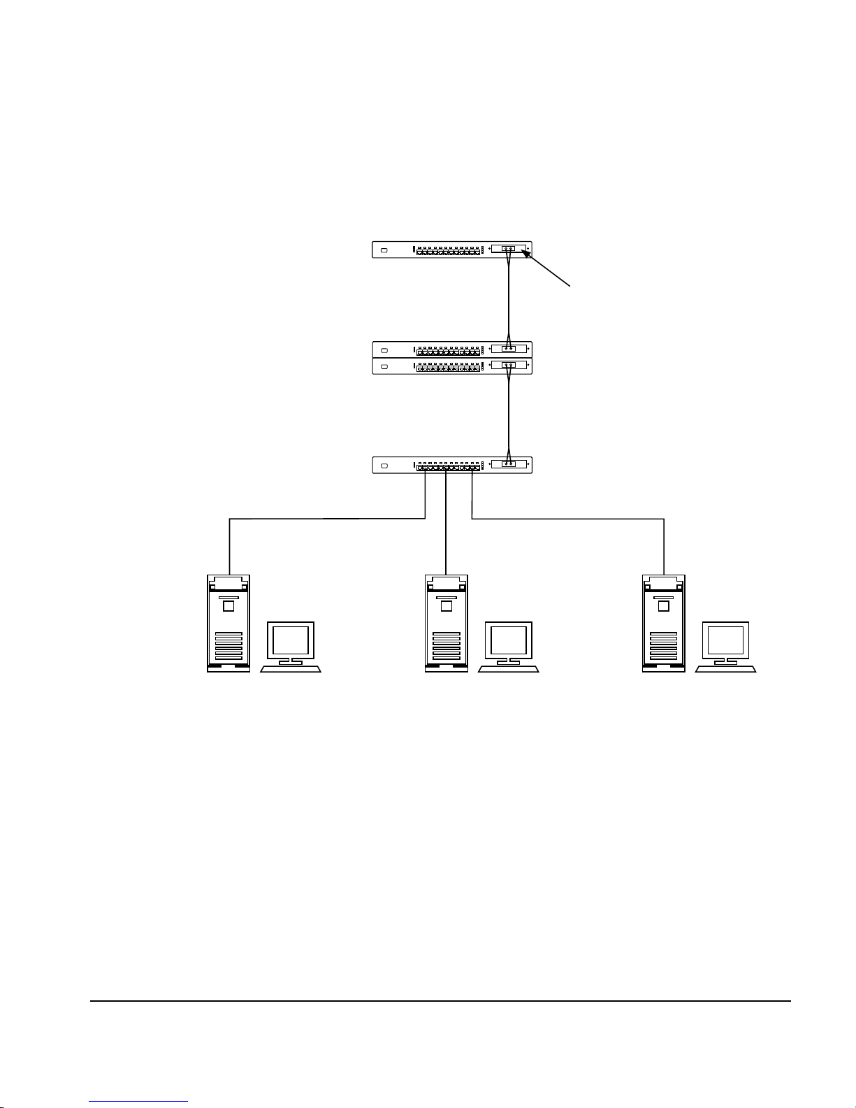
Smart Uplink Configuration 1
Fiber Uplink
(412 m)
Fiber Uplink
(412 m)
100 m 100 m
100 m
Smart Uplink Module
Figure 1-10.
Smart Uplink in a 100Base-FX Environment
Netelligent 3512/3612 100Base-T Repeater User Guide
Page 24
. . . . . . . . . . . . . . . . . . . . . . . . . . . . .
1-14 Overview
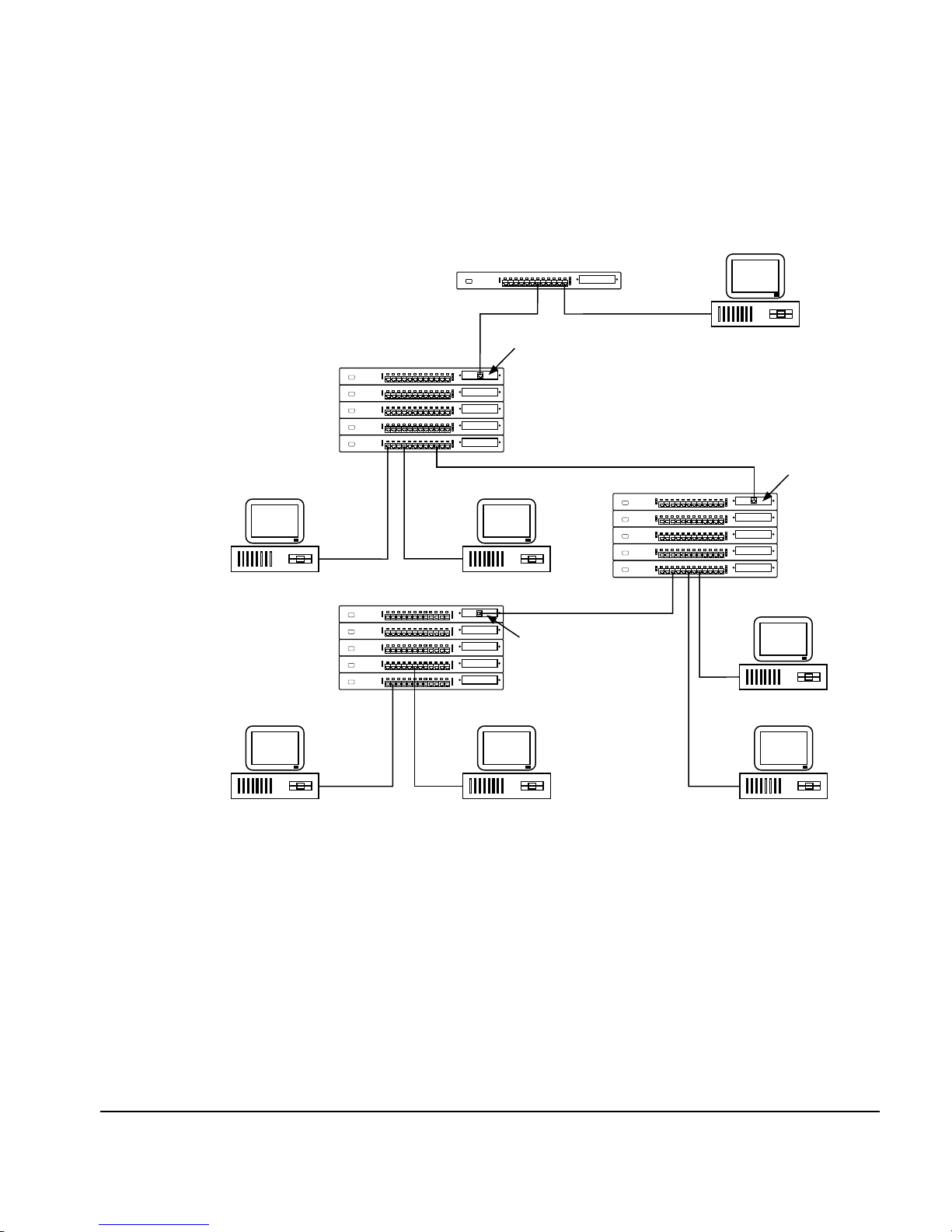
Smart Uplink Configuration 2
100Base-TX Repeater
100 m
100Base-TX Smart Uplink
100Base-TX Repeaters
TX Workstation TX Workstation
100 m 100 m
Mixed 100Base-TX and 100Base-T4 Repeaters
TX
TX
TX
T4
TX
100Base-T4 Smart Uplink
Module
100 m
Module
100 m
100 m
100Base-T4 Repeaters
TX Workstation
100Base-TX Smart Uplink
Module
100 m
T4 Workstation
Figure 1-11.
Smart Uplink with 100Base-TX and 100Base-T4
100 m 100 m
100 m
T4 WorkstationT4 WorkstationTX Workstation
Page 25

. . . . . . . . . . . . . . . . . . . . . . . . . . . . . .
1-15
Smart Uplink Configuration 3
100Base-TX Repeater
100Base-TX Repeater
Figure 1-12.
100Base-TX
Smart Uplink Module
100 m
100 m
100Base-TX Repeater
TX Workstation TX Workstation T4 WorkstationTX Workstation
100 m
Smart Uplink Module
Smart Uplink in a Hierarchical Environment
100Base-TX
100 m
100Base-T4 Repeater
100 m100 m100 m
100Base-TX
Smart Uplink Module
Netelligent 3512/3612 100Base-T Repeater User Guide
Page 26

. . . . . . . . . . . . . . . . . . . . . . . . . . . . . .
2-1
Chapter 2
Planning Repeater Installation
This chapter contains information that will help you prepare for installing the
repeater. This includes optional hardware, installation requirements, cable
requirements, and system planning charts.
Optional Hardware
In addition to the supplied hardware, your network installation might also
require the following optional items:
■
Redundant power supply
■
FlexPlane connector
■
Smart Uplink module
Installation Requirements
To help ensure a correct installation, read this section to determine the
hardware, environmental, electrical, and spatial requirements.
Environmental Requirements
Be sure the operating environment for the repeater is within the following
ranges:
■
Temperature: 32° to 104° F (0° to 40° C)
■
Humidity: 5% to 95% (non-condensing)
■
Altitude: 0 to 10,000 feet (0 to 9 km)
■
Clearance: minimum of 2 inches (5.1 centimeters) on each side of the
repeater to allow for proper ventilation
Netelligent 3512/3612 100Base-T Repeater User Guide
Page 27

. . . . . . . . . . . . . . . . . . . . . . . . . . . . .
2-2 Planning Repeater Installation
Electrical Requirements
The electrical requirements for a repeater are as follows:
■
Voltage: 100 to 240 VAC
■
Power: 1.5 (@ 100 VAC) to 0.90A (@ 240 VAC)
■
Frequency: 50 to 60 Hz
CAUTION: The power outlet must be a non-switched, grounded power
source. Do not use a three-to-two pronged adapter at an outlet. Doing so
may result in electrical shock and/or damage to the repeater and will void
your warranty.
NOTE: The repeater comes with a shielded AC power cord. If you lose or damage
the supplied shielded power cord, replace it with a shielded power cord that meets
local regulatory requirements to ensure emissions compliance.
Spatial Requirements
The repeater's dimensions (HxWxD) are 1.75 x 17.00 x 13.65 inches (4.5 x 43.6
x 35 cm).
You can interconnect up to five repeaters in one stack. Be sure to allow at least
2 inches (5.1 centimeters) on each side of the repeater for proper air circulation
and cable connections.
Cable Requirements
This section defines the requirements for cable used to connect the RJ-45 ports,
the Smart Uplink port, and the serial COM port on repeater.
Page 28

. . . . . . . . . . . . . . . . . . . . . . . . . . . . . .
2-3
Understanding Fast Ethernet Cable Budgets
A cable budget is the overall length of cable allowed between two DTEs (data
terminal equipment) in a single network segment. With Fast Ethernet, the cable
budget is affected by the type of network media between two DTEs and the
class of repeater used. The 3512 and 3612 100Base-TX repeaters are Class I
repeaters.
Fast Ethernet uses Ethernet's CSMA/CD protocol. Therefore, the cable budget
is based on the time it takes for part of an Ethernet packet to reach one end of
the network and for notification of an error (a collision) to return before the
entire packet is generated. This time period is called the propagation delay.
DTE
Packet
Figure 2-1.
Propagation Delay
Fast Ethernet transmits packets ten times faster than Ethernet. To compensate
for this timing difference, Fast Ethernet allows fewer repeaters per segment
than 10Base-T and allows a shorter distance between repeaters.
Checking Your Cable Budget
The following sections state the cabling distance limitations for 100Base-TX
and 100Base-FX. However, if your particular network installation deviates
from these examples, use the following guidelines to check your DTE-to-DTE
cable budget:
■
Locate the longest DTE-to-DTE cable run and add the lengths of all the
cables (UTP and/or fiber) between the two DTEs.
Repeater
Propagation Delay
Server
Netelligent 3512/3612 100Base-T Repeater User Guide
Page 29

. . . . . . . . . . . . . . . . . . . . . . . . . . . . .
2-4 Planning Repeater Installation
■
Find the appropriate cable budget in the table below and verify that the
cable length for your installation is less than or equal to the table entry.
■
If the cable run you chose contains fiber, locate the longest DTE-to-DTE
run in your installation that consists of only UTP cable and check its
cable budget, as well.
NOTE: Cable budgets apply only to DTE-to-DTE cable runs that are directly
connected or that pass through repeaters. If a Smart Uplink module, bridge, switch,
or router exists between the DTEs, the cable budget restarts when the transmission
passes through any of these devices.
Table 2-1 shows the maximum total length of cable allowed between any two
DTEs in a segment. (Information in this table was extracted from Table 29-2 of
the IEEE 802.3u specification.)
Table 2-1
Table of Maximum Cable Budgets in Meters (Feet in Parenthesis)
Connection Type
Direct
One Class I Repeater
One Class II Repeater
Two Class II Repeaters
NOTE: A UTP cable should never exceed 100 meters (328 feet) in length.
TX/T4 Only Fiber Only T4 and Fiber TX and Fiber
100 (328) 412 (1352) N/A N/A
200 (656) 272 (892) 231 (758) 261 (856)
200 (656) 320 (1050) 204 (669) 309 (1014)
205 (673) 228 (748) 236 (774) 216 (709)
Cable Types and Distance Limitations
The following information states the required cable type and distance
limitations for each Fast Ethernet category: 100Base-TX and 100Base-FX.
Page 30

. . . . . . . . . . . . . . . . . . . . . . . . . . . . . .
2-5
100Base-TX
100Base-TX is the IEEE 802.3u specification for transmitting 100 Mb/s Fast
Ethernet over two pairs of copper wire. The pinout, connectors (RJ-45 modular
plugs), and protocol (CSMA/CD) are exactly the same as for 10Base-T.
Unshielded Twisted Pair (UTP)
❏
Category 5 only
❏
Two pairs used (same as 10Base-T)
❏
Maximum 100-meter (328-foot) link
Shielded Twisted Pair (STP)
❏
Type 1
❏
Two pairs used (same as 10Base-T); other two pairs must be
terminated
Distance Rules
❏
One repeater hop per segment because the repeater is a Class I
repeater
❏
Collision domain diameter (total allowable distance end-to-end) is
200 meters (656 feet)
Figure 2-2 shows the maximum cable distance for a DTE-to-DTE connection
with one repeater repeater in the configuration using 100Base-TX cabling.
100m
DTE DTE
Figure 2-2. DTE-to-DTE 100Base-TX Connection
Repeater
100m
Netelligent 3512/3612 100Base-T Repeater User Guide
Page 31

. . . . . . . . . . . . . . . . . . . . . . . . . . . . .
2-6 Planning Repeater Installation
Figure 2-3 shows a one-to-one cable pinout for 100Base-TX.
TX+
1
TXRX+
RX-
8
RX+
RXTX+
TX-
1
8
DTE Repeater
Figure 2-3. One-to-One Cable Pinout for 100Base-TX
NOTE:
To prevent potential electromagnetic interference, terminate the unused
wires (4, 5, 7, and 8).
Figure 2-4 shows the crossover cable pinout for 100Base-TX.
1
2
3
4
5
6
7
8
1
2
3
4
5
6
7
8
DTE
or
Repeater Repeater
(when no uplink port is used)
DTE
Figure 2-4. Crossover Cable Pinout for 100Base-TX
100Base-FX
100Base-FX is the IEEE 802.3u specification for transmitting 100 Mb/s Fast
Ethernet over two strands (one pair) of fiber optic cable.
Cable Type
❏
Fiber optic
❏
Multi-mode 62.5/125 to 100/150 micron fiber
❏
Both strands used
Page 32

. . . . . . . . . . . . . . . . . . . . . . . . . . . . . .
2-7
Media Connection Options
❏
Low-cost fiber optic interface connector (SC type; Part No. 267043-
001)
❏
Optical medium connector plug and socket (ST type; Part No.
267042-001)
❏
Media interface connector (MIC) as specified in ANSI X3T9.5
MMF-PMD
Distance Rules
❏
One repeater hop per segment
❏
Collision domain diameter (total allowable distance end-to-end) is
272 meters (892 feet)
Figure 2-8 shows the maximum cable length for an FX SUM-to-FX
SUM fiber connection (412 meters, 1352 feet)
100Base-FX
Uplink Module
100Base-T Repeater
with 100Base-FX Uplink Module
Figure 2-5. FX SUM-to-FX SUM (Fiber) Connection
412m
100Base-T Repeater
with 100Base-FX Uplink Module
Figure 2-9 shows the maximum cable distance for a DTE-to-DTE
connection with one repeater in the configuration using 100Base-FX
cabling.
136m
DTE DTE
Class I
Repeater
Figure 2-6. DTE-to-DTE 100Base-FX Connection
136m
Netelligent 3512/3612 100Base-T Repeater User Guide
Page 33

. . . . . . . . . . . . . . . . . . . . . . . . . . . . .
2-8 Planning Repeater Installation
Smart Uplink Port Cable
The SUM requires the following types of cable:
■
TX Version (Part No. 267045-001) Standard 4-wire twisted-pair
(UTP or STP), Category 5
■
FX ST Type (Part No. 267042-001) Multi-mode 62.5/125 micron
fiber
■
FX SC Type (Part No. 267043-001) Multi-mode 62.5/125 micron
fiber
Modem Cable
You can use a standard EIA RS-232 cable to connect the serial COM port,
located on the front panel of the managed 100Base-T repeater (Model 3612), to
a modem. This lets you perform out-of- band management and Flash (firmware)
downloads via a remote dial-up to the modem. When you connect a PC to the
serial interface for local management, you must use an EIA RS-232 null
modem cable.
Page 34

. . . . . . . . . . . . . . . . . . . . . . . . . . . . . .
2-9
System Planning Charts
The charts in Figures 2-10 and 2-11 provide a convenient way of planning the
connections for your repeater.
Repeater Setup and Cabling Chart
Date
Unit Number
Building
Location
Rack Mount
Table Mount
MAC Address
IP Address
Installed Uplink Module
None
TX
FX (Fiber)
Port Connects To
8 9 10 11 12
7
6
4 5
Installed Redundant
Power Supply Module
Figure 2-7.
Repeater Setup and Cabling Chart
1 2 3
Uplink
Module
Netelligent 3512/3612 100Base-T Repeater User Guide
Page 35

. . . . . . . . . . . . . . . . . . . . . . . . . . . . .
2-10 Planning Repeater Installation
Rack Inventory Chart
Use this chart to record the devices installed in a particular rack.
Wiring Closet Number
Rack Number
Installer
Date
Figure 2-8. Rack Inventory Chart
Example
100Base-T Repeater
100Base-T Repeater
Page 36

. . . . . . . . . . . . . . . . . . . . . . . . . . . . . .
3-1
Chapter 3
Installing the Repeater
This chapter explains how to mount the repeater, attach cables, install a Smart
Uplink module, interconnect repeaters, and install a redundant power supply
module.
Mounting the Repeater
You can place the repeater on a level surface (table top or shelf, for example) or
mount it in a standard EIA 19-inch rack.
Attaching the Rubber Feet
If you will place the repeater on a table top or shelf, attach the supplied
adhesive-backed rubber feet as described in the following steps.
1. Turn the repeater over so that its bottom side faces up.
2. Remove the four rubber feet from their packaging.
3. Peel the protective paper backing off the rubber feet. Then position the
feet near the corners of the repeater and press the feet into place.
4. Turn the repeater to its upright position and place it on the mounting
surface.
NOTE: Be sure you allow at least 2 inches (5.1 cm) on each side of the repeater for
proper air flow.
Rack-Mounting the Repeater
To mount the repeater in a rack, use the supplied mounting brackets, 3/8-inch
bracket screws, and 1/2-inch rack-mount screws.
Netelligent 3512/3612 100Base-T Repeater User Guide
Page 37

. . . . . . . . . . . . . . . . . . . . . . . . . . . . .
3-2 Installing the Repeater
To rack mount the repeater, follow these steps:
1. Remove the screws from the left and right sides of the repeater. (These
screws are extras and are not needed to install the mounting brackets.)
2. Position the right bracket as shown in Figure 3-1 and attach it to the
repeater using four of the smaller, 3/8-inch bracket screws. Then tighten
the screws. Repeat this step to attach the left mounting bracket.
Bracket Screws
9101112
XXXX
COL
BP1
BP2
BP3
Figure 3-1. Attaching the Mounting Brackets
3. After you attach both mounting brackets, position the bracket slots over
the desired holes on the rack (Figure 3-2). Then insert and tighten the
four 1/2-inch rack-mount screws.
1
COM PORT
MGMT STATUS
XXXXXXXXXXXX
XXXXXXXXXXXX
2345 67 91011128
PWR A
PWR B
Rack-mount Screws
Figure 3-2. Positioning the Repeater in a Rack
COL
BP1
BP2
BP3
Page 38

. . . . . . . . . . . . . . . . . . . . . . . . . . . . . .
3-3
Installing a Smart Uplink Module
The repeater has a Smart Uplink bay that lets you install one of the following
optional Smart Uplink modules (SUMs):
➀
■
■
■
100Base-TX version (Part No. 267045-001)
➁
100Base-FX (fiber) version with ST connector (Part No. 267042-
001)
➂
100Base-FX (fiber) version SC connector (Part No. 267043-001)
Figure 3-3. Optional Smart Uplink Modules
The Smart Uplink port is the 13th logical port on the repeater.
Inserting the SUM
To insert a SUM, follow these steps:
1. Power down the repeater.
Smart Uplink
Module
100BASE-TX
Smart Uplink
Module
ACTIVITY
COLLISION
TX RX
100BASE-FX
Smart Uplink
Module
ACTIVITY
COLLISION
ACTIVITY
COLLISION
100BASE-FX
2. Remove the Smart Uplink Port cover plate from the repeater's front
panel.
3. Insert the SUM through the port hole, aligning the sides of the SUM
with the card guides inside the repeater (Figure 3-4).
Netelligent 3512/3612 100Base-T Repeater User Guide
Page 39

. . . . . . . . . . . . . . . . . . . . . . . . . . . . .
3-4 Installing the Repeater
4. Carefully push the SUM's 50-pin male connector into the SUM socket
on the repeater motherboard until the SUM is firmly seated and its
faceplate is flush with the repeater's front panel.
5. Secure the SUM to the repeater by tightening the SUM's spring screws.
1
COM PORT
MGMT STATUS
PWR A
PWR B
234 567 91011128
XXXXXXXXXXXX
COL
BP1
BP2
BP3
Figure 3-4. SUM Installation
Connecting Twisted-Pair Cable
Each RJ-45 port on the repeater can accept a standard 8-wire twisted-pair (UTP
or STP) cable that ends with an RJ-45 connector. These ports can support cable
lengths up to 100 meters (328 feet). The TX models use Category 5 cable.
To attach twisted-pair cable, plug one of the RJ-45 connectors into the selected
port on the repeater. Connect the other RJ-45 connector into a 100Base-Tequipped device.
Smart Uplink
SMARTUP-TX
Module
100BASE-TX
ACTIVITY
COLLISION
Page 40

. . . . . . . . . . . . . . . . . . . . . . . . . . . . . .
3-5
100Base-TX Repeater
1
2345 67 91011128
XXXXXXXXXXXX
COM PORT
MGMT STATUS
PWR A
PWR B
Figure 3-5. Connecting Twisted-Pair Cable
100Base-T Workstation
COL
BP1
BP2
BP3
Interconnecting Repeaters
You can interconnect up to five 3512/3612 100Base-T repeaters to form one
logical repeater that supports up to 60 Fast Ethernet ports. A managing repeater
(Model 3612) can exist anywhere in a stack.
Each repeater has an expansion interface that is comprised of two 100-pin
connectors (UP and DOWN) on the repeater's back panel. Figure 3-6 shows
how the UP connector of a bottom repeater connects to the DOWN connector
of an adjacent upper repeater via a FlexPlane connector (Part No. 810172-000).
If possible, mount the repeaters on a rack or place them on a stable mounting
surface with the supplied rubber feet affixed before you attach the FlexPlane
connector. This helps ensure the correct spacing between repeaters and helps
prevent stretching and possibly damaging the FlexPlane cable during
installation.
Netelligent 3512/3612 100Base-T Repeater User Guide
Page 41

. . . . . . . . . . . . . . . . . . . . . . . . . . . . .
3-6 Installing the Repeater
WARNING: The FlexPlane connector is not hot swappable. Be sure you
power down the entire repeater stack before you connect repeaters.
PWR A
PWR A
Figure 3-6.
Interconnecting Repeaters with a FlexPlane Connector
Connecting Power
Follow these steps to connect the repeater to power:
1. Plug the power cord into the power cord connector on the back of the
repeater.
PWR A
100-240 VAC, 3A-1.5A,50/60 HZ
100-240 VAC, 3A-1.5A,50/60 HZ
Power Cord Connector
100-240 VAC, 3A-1.5A,50/60 HZ
PWR B
PWR B
PWR B
DOWN
UP
DOWN
Backplane
Connector
UP
DOWN
UP
Figure 3-7.
2. Insert the three-pronged plug on the power cord into a non-switched,
grounded power source that is near the repeater and easily accessible.
Connecting Power
Page 42

. . . . . . . . . . . . . . . . . . . . . . . . . . . . . .
3-7
WARNING: Plugging in the power cord applies power to the repeater.
There is no ON/OFF switch on the repeater.
When you plug in the power cord, the repeater performs a power-on self test
(POST) which lasts approximately 1 minute, depending on the amount of
DRAM installed in the repeater (see Appendix C, “Upgrading the DRAM”).
After a successful POST, the LEDs indicate the current operating status. See the
“LED Indicators” section in Chapter 1, “Overview” for more information about
the LED status.
If the POST fails, the STATUS LED flashes yellow. If this occurs, disconnect
the repeater from power and then reconnect power. If the problem continues,
contact Compaq Technical Support.
Disconnecting Power
To disconnect power from the repeater, remove the power cord from the power
source. Do not remove the power cord from the power cord connector on the
repeater to disconnect power. Figure 3-8 shows the correct and incorrect ways
of disconnecting power from the repeater.
Unplug the Power Cord
From the Grounded Power Source
Figure 3-8.
Disconnecting Power
Do
Do Not
Unplug the Power Cord
From the Repeater’s
Power Cord Connector
PWR A
100-240 VAC, 3A-1.5A,50/60 HZ
Netelligent 3512/3612 100Base-T Repeater User Guide
Page 43

. . . . . . . . . . . . . . . . . . . . . . . . . . . . .
3-8 Installing the Repeater
Installing a Redundant Power Supply
Module
The repeater comes with a pre-installed, 90-watt power supply module (PWR
A). You can install an optional redundant power supply module (PWR B) for
backup power. Contact your reseller for information about ordering an
additional power supply module (Part No. 267322-001).
Follow these steps to install a redundant power supply module.
NOTE:
You can install the redundant power supply module while the main power
supply module is powered on.
1. Remove the two screws from the PWR B cover plate and remove the
plate. Be sure you keep the cover plate and screws in case you need
them for future use.
2. Carefully insert the power supply module into the opening until its
10-pin connector engages with the internal power connector and the face
of the module is flush with the repeater's back panel.
3. Secure the power supply by tightening its two spring screws.
PWR A
Figure 3-9.
PWR B
Redundant Power Supply Module
Spring Screws
Inserting a Redundant Power supply
UP
DOWN
4. Plug the power cord into the power cord connector on the new power
supply module.
5. Insert the power cord's three-pronged plug into a non-switched, grounded
power source.
Page 44

. . . . . . . . . . . . . . . . . . . . . . . . . . . . . .
3-9
WARNING: Plugging in the power cord applies power to the repeater.
There is no ON/OFF switch on the repeater.
When you connect the repeater to power, the PWR B LED indicator
lights green to indicate that the power supply module is installed and
functioning correctly.
NOTE: If the power supply module does not have power or is not functioning
correctly, the PWR B LED indicator lights yellow.
Netelligent 3512/3612 100Base-T Repeater User Guide
Page 45

. . . . . . . . . . . . . . . . . . . . . . . . . . . . .
4-1
Chapter 4
Repeater Management
This chapter contains information about repeater management. The 3612
100Base-T managed repeater contains a 100 Mb/s management daughter card.
The card has a management agent that manages a 100 Mb/s repeater stack
through a management bus in the FlexPlane connector. The repeaters
communicate with the management agent either in-band via Ethernet or out-ofband via RS-232 (serial) communication channels. The following sections
discuss management related topics, including supported MIBs and frame types,
IP and IPX support, the VT100/Telnet management interface, and RMON
(Remote MONitor) support.
Supported MIBs
The repeater supports the following MIBs (Management Information Bases):
■
RFC1213 (MIB II)
■
RFC1516 (Standard repeater MIB)
■
RFC1271 (RMON MIB)
■
Proprietary MIB (MDC100.MIB)
■
Novell proprietary repeater MIB (to allow Novell Management Services
to directly manage the repeater)
Supported Frame Types
The repeater supports the following frame types:
■
802.2 (IPX)
■
802.3 Raw (IPX)
■
802.2 SNAP (IPX and IP)
■
Ethernet_II (IPX and IP)
Netelligent 3512/3612 100Base-T Repeater User Guide
Page 46

. . . . . . . . . . . . . . . . . . . . . . . . . . . . .
4-2 Hub Management
NVRAM
Hub management configuration information supplied by the SNMP manager or
the console manager (VT100 or Telnet) is stored in NVRAM (Non-Volatile
RAM). This enables the repeater to recover from a power failure with its full
configuration intact.
CAUTION:
motherboard contains a non-replaceable lithium battery. Only trained service
personnel should dispose of this chip.
SNMP Management
The repeater supplies SNMP management through both in-band and out-ofband communications.
The repeater provides in-band SNMP support through:
■
UDP/IP and Novell's IPX protocol stacks
■
Telnet through TCP/IP for VT100 emulation
■
Proprietary protocol using IPX
The repeater provides out-of-band management through:
■
Serial Line IP (SLIP)
■
Serial interface using VT100 emulation
The non-volatile SRAM chip (Socket U1) on the repeater's
IP Support
The repeater supports the following Internet protocols:
■
ARP Address Resolution Protocol
■
RARP Reverse Address Resolution Protocol
■
BOOTP Boot Protocol
Page 47

. . . . . . . . . . . . . . . . . . . . . . . . . . . . . .
4-3
■
ICMP Internet Control Message Protocol
■
UDP User Datagram Protocol
■
TCP Transmission Control Protocol
■
SNMP Simple Network Management Protocol
■
TFTP Trivial File Transfer Protocol
ARP, RARP, and BOOTP provide Internet address resolution capabilities. The
repeater uses ARP to resolve the MAC address of any known Internet address
with which it needs to communicate. The repeater uses RARP and BOOTP to
resolve its own Internet address based on the MAC address it was assigned by
the factory.
ICMP messages allow IP routers to communicate with various hosts in order to
report abnormal conditions or to send new routing information.
The repeater uses IP fragmentation to provide a seamless interface for
management software regardless of the physical constraints of the network
interface. IP messages can be up to 1520 bytes long.
IP Autodiscovery Support
Some SNMP management platforms, such as HP OpenView, cannot discover
repeaters that are not in the ARP cache of a gateway or router. Therefore, it is
necessary to regularly update the cache with the IP address of the repeater to be
autodiscovered. When IP communication stops between the agent and the
SNMP management software, the ARP cache on the gateway or router removes
the agent's address because the agent no longer updates the ARP cache of the
gateway or router. The repeater periodically updates the cache by transmitting
an ICMP ping to the gateway.
Netelligent 3512/3612 100Base-T Repeater User Guide
Page 48

. . . . . . . . . . . . . . . . . . . . . . . . . . . . .
4-4 Hub Management
IPX Support
The repeater supports SNMP over Novell's IPX protocol in addition to SNMP
over IP. Using SNMP/IPX and Novell's repeater MIB, Novell's NMS can
directly manage the repeater. The repeater also supports SAP (Service
Advertising Protocol), RIP (Routing Information Protocol), and IPX
diagnostics protocols. These features make the repeater HMI (Hub Management
Interface) compliant.
Using SAP, the repeater advertises itself as an HSL service. When Novell's
NMS initiates autodiscovery, it produces bindery requests through NCP
(NetWare Core Protocol) to a NetWare server. This allows NMS to obtain the
internal network number of the repeater's HSL server. RIP allows NMS to
obtain the MAC address and other necessary information to start SNMP over
IPX communication. IPX diagnostics is implemented only to support the
NetExplorer server. This protocol is not directly involved with the NMS
autodiscovery algorithm.
The proprietary IPX repeater protocol, as well as SNMP, is supported over
Novell's IPX protocol stack. The implementation of this protocol provides
support for Redirector. Through the Redirector, Novell's Hubcon can manage
the repeater.
The repeater IPX proprietary protocol provides a mechanism over IPX to set
the IP address. Since the IPX address of a repeater is derived from the network
number and the hardware MAC address, you do not need to set an address for
IPX communication. Using the proprietary protocol, you can set the IP address,
subnet mask, default gateway IP address, SNMP write community, IPX frame
type, RARP and BOOTP, SAP broadcast disable, and an additional parameter
for the frame type.
The repeater supports IPX over Ethernet II, 802.3 RAW, 802.2 Type I and II,
and 802.2 SNAP frame types.
Page 49

. . . . . . . . . . . . . . . . . . . . . . . . . . . . . .
4-5
RMON Support
The repeater's remote monitoring (RMON) support allows the management
system, such as HubView network management software, to remotely monitor
the repeater for diagnostic purposes. The repeater supports four RMON groups
including Statistics, History, Alarm, and Event.
Statistics Group
The Statistics group contains statistics measured for a collision domain. This
helps indicate the load on a collision domain and the overall health of the
domain by reporting conditions such as CRC (cyclic-redundancy check)
alignment errors, collisions, and undersize and oversize packets.
History Group
The History group records periodic statistical samples from the collision
domain and stores them in an SNMP table for later retrieval. The historyControl
table stores configuration entries, each of which defines an interface, polling
period, and other parameters. Once samples are taken, the sample data is stored
in an entry in a media-specific table. Each such entry defines one sample and is
associated with the historyControl entry that caused the sample to be taken. The
only media-specific table defined is the etherHistoryTable, for Ethernet
networks. You can specify the number of samples and sample interval.
You can sample the following variables:
■
■
■
■
■
■
Octets
BroadcastPkts
MulticastPkts
CRCAlignErrors
UndersizePkts
OversizePkts
■
Fragments
Netelligent 3512/3612 100Base-T Repeater User Guide
Page 50

. . . . . . . . . . . . . . . . . . . . . . . . . . . . .
4-6 Hub Management
■
Jabbers
■
Collisions
■
Utilization
Alarm Group
The Alarm group periodically takes statistical samples from variables and
compares them to previously configured thresholds. The alarm table stores
configuration entries, each of which defines a polling period and various
threshold values. If a monitored variable exceeds a threshold value, the repeater
generates an event. No more events are generated for that threshold until the
opposite threshold is exceeded. You can limit the generation of events via the
MIB. When sampling a delta value, you can increase the precision of the
sample by taking the sample twice per period and comparing the sum of the
latest two samples to the threshold. This allows the repeater to detect threshold
crossings that span the sampling boundary. This does not require any special
configuration of the threshold value.
Event Group
The Event group controls the generation and notification of events from the
repeater. Each entry in the eventTable describes the event's parameters that can
be triggered. The repeater generates an event when an associated condition is
present in the MIB. The event can trigger a related function in the MIB. Each
eventEntry can specify that, when an event occurs, a log entry and an SNMP
trap message is created for the event. The community for the SNMP trap
message is contained in the associated eventCommunity object. The condition
that triggers the event determines the enterprise and specific trap fields of the
trap. If the eventTable is triggered by a condition specified elsewhere, the
enterprise and specific trap fields must be specified for traps generated for that
condition.
Page 51

. . . . . . . . . . . . . . . . . . . . . . . . . . . . . .
4-7
Intrusion Protection
The repeater's firmware supports intrusion protection, which provides a method
of preventing unauthorized access to the network. Intrusion protection allows
any SNMP manager to configure one MAC address per port and to enable or
disable intrusion protection on a per port basis.
Do not set intrusion protection on an uplink port that receives multiple MAC
addresses. Otherwise, the repeater partitions the port.
HubView for NMS v1.1 does not support intrusion protection.
Follow these steps to enable intrusion protection for a port:
1. Using an SNMP MIB browser, set the authorized MAC address in the
mdcIntrusionPortMACAddress or mdcIntrusionPortMACAddressStr
MIB variable.
2. Set the mdcIntrusionPortStatus MIB variable to enable(2).
Once you configure intrusion for a port, the repeater's firmware monitors the
port for intruders. If the port detects an unauthorized MAC address, the repeater
partitions the port, sets mdcIntrusionPortStatus variable to tripped(3), and
generates a Novell Health State trap in the trap table.
To restore the port after it detects an intruder, use an SNMP manager to set the
rptrBasPortAdminState MIB variable (located in the Novell MIB) to enable(2).
Changing the Status of a Port
The SNMP manager lets you change the intrusion status of a port via the
mdcIntrusionPortStatus MIB variable. To do so, follow these steps:
1. Verify that the mdcSecurityStatus MIB variable is set to disable(1).
2. Set the mdcIntrusionPortStatus MIB variable to disable(1) or enable(2).
NOTE:
If the SNMP manager tries to change the settings of mdcIntrusionPortStatus
when mdcSecurityStatus is set to enable(2), a PDU error occurs. See “Security” in
the next section for more information about the mdcSecurityStatus settings.
Netelligent 3512/3612 100Base-T Repeater User Guide
Page 52

. . . . . . . . . . . . . . . . . . . . . . . . . . . . .
4-8 Hub Management
Security
The security feature provides further network security by restricting access to
the mdcIntrusionPortStatus, mdcIntrusionPortMACAddress, and
mdcIntrusionPortMACAddressStr MIB variables. You can restrict access to
these intrusion table MIB variables by setting the mdcSecurityStatus MIB
variable to enable(2). The default value is disable(1), which allows the SNMP
manager to directly access the intrusion table through normal SNMP set PDUs
(Protocol Data Units).
CAUTION:
directly disable security; you must use the mdcSecurityResetStatus MIB
variable to indirectly set mdcSecurityStatus to disable(1). If you need to set
values in the intrusion table after you enable security, you must do so using
the mdcSecurityCommand MIB variable (an encrypted value). Do not set
mdcSecurityStatus to enable(2) unless the SNMP manager can encrypt
values for the mdcSecurityCommand and mdcSecurityResetStatus MIB
variables. Do not use a MIB browser to enable security.
Once you set mdcSecurityStatus to enable(2), you cannot
Configuring the Repeater at Bootup
You can configure a BOOTP server to supply the IP address, subnet mask, and
a default gateway IP address for a particular hardware MAC address. When you
power up a repeater stack, the managed repeater uses the information stored in
NVRAM to configure the repeater at bootup. There are two boot phases: Boot
and Runtime.
In the Boot phase, the STATUS LED is yellow. If BOOTP/RARP requests are
enabled, the repeater issues as many requests as are defined in the
mdcBootpRarpRetries MIB object in the MDC100 MIB (and displayed in the
VT100 console interface). The default number of requests is two. The repeater
issues the requests using two different frame types (Ethernet_II and 802.2
SNAP). The interval between requests is defined in the
mdcBootpRarpRetryInterval MIB object. The default request retry interval is 5
seconds.
Page 53

. . . . . . . . . . . . . . . . . . . . . . . . . . . . . .
4-9
In the Runtime phase, the STATUS LED is green. If BOOTP/RARP requests
are enabled and the repeater does not have an IP address currently assigned, the
repeater issues requests every 5 minutes using only one frame type (same as the
IP frame type).
If the repeater receives a response from either type of server, the managing
repeater uses the information and configures the stack accordingly.
If desired, you can use your network management software or the serial
interface to set the mdcBootpRarpRequests MIB variable so that the repeater
does not issue BOOTP/RARP requests. This is preferred if you use only IPX
communication, as it helps reduce unnecessary traffic generated by the repeater.
NOTE: A RARP server provides only an IP address. A BOOTP server is required to
automate downloads.
Using the VT100 Serial Port/Telnet
Management Interface
In addition to SNMP and RMON network management, the repeater supports
out-of-band management via a serial port connection and in-band management
via a Telnet connection. This lets you set numerous management parameters,
including the IP address and subnet mask for both the Ethernet and serial
interface, as well as the default gateway IP address and SNMP write
community for the Ethernet interface. The VT100 interface has two distinct
modes of operation, Boot and Runtime, which let you perform the following
management operations:
Boot Mode (STATUS LED is orange)
■
View and edit system information
■
Download firmware via XMODEM or TFTP (over Ethernet)
■
Set up the modem
■
Change the password
Netelligent 3512/3612 100Base-T Repeater User Guide
Page 54

. . . . . . . . . . . . . . . . . . . . . . . . . . . . .
4-10 Hub Management
Runtime Mode (STATUS LED is green)
All of the above functions plus:
■
View and edit port and port group statistics/status
■
Change the backup port configuration
■
Change the stack configuration
■
Download firmware via TFTP over SLIP (if the session is running
through Telnet over an Ethernet connection)
Setting up the Terminal Emulation Program
Set up the terminal emulation program with the following settings:
■
8 data bits
■
1 stop bit
■
No parity
■
9600 bps
■
No flow control
NOTE: If you use the Windows Terminal program, select
Settings
the
Windows
menu. Then uncheck the
Use Function, Arrow, and Ctrl Keys for
option box. This enables the arrow keys to function correctly in the
interface program.
Terminal Preferences
from
Page 55

. . . . . . . . . . . . . . . . . . . . . . . . . . . . . .
4-11
Starting the Management Session
NOTE:
The Login screen in the VT100 console interface requires that you enter your
password within a specific amount of time.
When you apply power to the repeater, the Boot phase starts (the STATUS
LED is yellow). After about 20 seconds, the STATUS LED changes to green to
indicate that the repeater is in the Runtime phase and is ready for the
management session.
After the repeater has entered the Runtime mode, follow these steps to start a
management session.
If the repeater uses a null modem connection, start with Step 1.
If the repeater uses a regular modem connection, start with Step 2.
1. In the Runtime mode, the repeater firmware displays a modem
initialization string every 10 seconds, with each string representing a
different baud rate (19.2K, 14.4K, 9600, and 2400). When the firmware
detects the baud rate that matches the terminal baud rate, it displays a
readable alphanumeric character string similar to the following:
at&fs0=1
2. Within 20 seconds after a readable alphanumeric character string
appears, enter the following command:
VT100
The Login screen appears.
Figure 4-1.
Login Screen
Netelligent 3512/3612 100Base-T Repeater User Guide
Page 56

. . . . . . . . . . . . . . . . . . . . . . . . . . . . .
4-12 Hub Management
NOTE: If the 20 seconds expires before you enter VT100, you must wait for the
port to cycle back to the modem initialization string.
3. Within 20 seconds after the Login screen appears, enter the password.
The default password is <public>. The Main menu screen appears.
NOTE: The following screen shows the Runtime main menu. If you start the
VT100 session while the STATUS LED is orange (for less than 1 minute after
you power up the repeater), the Boot main menu appears. This menu differs
slightly from the Runtime menu. To get to the Runtime main menu from the
Boot main menu, you must end the VT100 session, wait for the STATUS LED to
turn to green, and then restart the VT100 session.
Figure 4-2.
Main Menu Screen
Error Messages
If you enter an incorrect password, the following error message appears:
ERROR: Password incorrect, please re-enter.
If you forget the password, contact Compaq Technical Support.
Page 57

. . . . . . . . . . . . . . . . . . . . . . . . . . . . . .
4-13
Navigating Menu Option Screens
To select a menu option from the Main menu screen, use the Tab key or arrow
keys to position the cursor on the option. Then press the Enter key to display
the screen for the selected option.
Each menu option screen displays the system time, system name, and repeater
IP address. Some menu options screens let you edit various fields, which are
highlighted. Other screens allow you only to view the information on the
screen. Un-editable fields are in normal text (not highlighted).
Use the following methods to navigate a menu option screen:
■
To move the cursor from one field to the next, press the Tab key or the
arrow keys. Press the right or down arrow key to move the cursor
forward, and press the left or up arrow key to move the cursor backward.
When the cursor is on a field, it blinks to indicate its position.
■
Multiple-choice fields are enclosed in left and right angle brackets (<>).
To toggle between options for a field, press the space bar.
■
To apply changes to all modified fields and return to the main menu,
move the cursor to the Accept changes box and press the Enter key. To
return to the main menu without saving changes, move the cursor to the
Cancel changes field and press the Enter key.
■
To execute an operation, press the Enter key.
NOTE: If you use the Windows Terminal program, select
Settings
the
Windows
menu. Then uncheck the
Use Function, Arrow, and Ctrl Keys for
option box. This enables the arrow keys to function correctly in the
Terminal Preferences
interface program.
The following sections describe each menu option screen.
from
Netelligent 3512/3612 100Base-T Repeater User Guide
Page 58

. . . . . . . . . . . . . . . . . . . . . . . . . . . . .
4-14 Hub Management
Viewing System Information
The System Information screen shows the primary system identification
information.
Figure 4-3.
■
■
System Information Screen
You can select the following IP frame types: Ethernet II or Ethernet
802.2 SNAP
You can select the following IPX frame types: Ethernet II, Ethernet
802.2, Ethernet 802.3, or Ethernet 802.2 SNAP
Error Messages
The following error message can occur if there are incorrect entries:
ERROR: The field must be in the range [0...255]
The following error messages can occur if entered values are out of range:
ERROR: The value is too small
Page 59

. . . . . . . . . . . . . . . . . . . . . . . . . . . . . .
4-15
ERROR: The value is too large
Viewing the Stack Configuration
The Stack Configuration screen shows the unit number, backplane number,
backplane type, managed status, and unit description. You can change only the
backplane number (1, 2, 3, or Isolated). When you make a change, the change
becomes effective immediately.
Figure 4-4.
The Managed Status field indicates the status of the repeater’s hardware
management override switch setting (see “Appendix B: Internal DIP Switch”).
If the field reads Yes, the switch is at its default (no management override)
setting.
Stack Configuration Screen
Netelligent 3512/3612 100Base-T Repeater User Guide
Page 60

. . . . . . . . . . . . . . . . . . . . . . . . . . . . .
4-16 Hub Management
Viewing the Backup Port Configuration
The Backup Port Configuration screen shows information about the slot
number of the primary and backup port and the current status of the ports. The
screen also lets you add, delete, and enable or disable the state of backup port
entries.
Figure 4-5.
Backup Port Configuration Screen
Adding a Backup Port Entry
To add a backup port entry, follow these steps:
1. From the Action field, move the cursor to the Primary Unit entry field.
Then enter the number of the desired primary unit.
2. Move the cursor to the Primary Port entry field. Then enter the number of
the desired primary port.
3. Move the cursor to the Backup Unit entry field. Then enter the number of
the desired backup unit.
Page 61

. . . . . . . . . . . . . . . . . . . . . . . . . . . . . .
4-17
4. Move the cursor to the Backup Port entry field. Then enter the number of
the desired backup port.
5. Move the cursor to the Action field and press the space bar until Add
appears.
6. Press the Enter key. The new backup port entry appears in the backup port
configuration list.
Deleting a Backup Port Entry
To delete a backup port entry, follow these steps:
1. Press the - or + keys to highlight a backup port entry.
2. Move the cursor to the Action field and press the space bar until Delete
appears.
3. Press the Enter key.
Updating the State of a
Backup Port Entry
To update the state of a backup port entry, follow these steps:
1. Press the - or + keys to highlight a backup port entry.
2. Move the cursor to the State entry field.
3. Press the space bar until the desired option (Disabled or Enabled) appears.
4. Press the Enter key.
Error Messages
The following error messages can occur if there are incorrect entries:
ERROR: Input fields not complete
ERROR: Unable to set backup group
Netelligent 3512/3612 100Base-T Repeater User Guide
Page 62

. . . . . . . . . . . . . . . . . . . . . . . . . . . . .
4-18 Hub Management
ERROR: Invalid module
ERROR: Invalid port number
ERROR: Unable to set backup group and port
To move to the Return to menu field, the cursor must first be in the Action
field.
Viewing Port Statistics
The Port Statistics screen shows statistical information for each port, as shown
in the following illustration.
Figure 4-6.
To scroll forward or backward to other ports, move the cursor to the Scroll field
and press the < and > keys. To scroll forward or backward to other units, move
the cursor to the Scroll field and press the - and + keys.
Port Statistics Screen
Page 63

. . . . . . . . . . . . . . . . . . . . . . . . . . . . . .
4-19
NOTE: Refer to the glossary for definitions of these statistics.
Viewing Port Group Statistics
The Port Group Statistics screen shows statistical information for a specific port
group. This information includes the unit number, backplane number,
backplane type, managed status, readable frames, and collisions.
Figure 4-7.
Port Group Statistics Screen
Netelligent 3512/3612 100Base-T Repeater User Guide
Page 64

. . . . . . . . . . . . . . . . . . . . . . . . . . . . .
4-20 Hub Management
Changing Your Password
The Change Password screen lets you change your current password. To
change your password, follow these steps:
1. Enter the old password in the Old password field.
NOTE:
You must enter information in the Old password field to advance the
cursor to the New and Verify password fields.
2. Enter the new password in the New password and Verify password fields.
3. Press the Enter key.
Figure 4-8.
Change Password Screen
Error Messages
The following error messages can occur if there are incorrect entries:
ERROR: Old password not valid
Page 65

. . . . . . . . . . . . . . . . . . . . . . . . . . . . . .
4-21
ERROR: Verify Password does not match New Password
Downloading Firmware
The Download Firmware screen lets you download an updated version of
firmware. You can download Runtime only or a combination of Boot and
Runtime. The download can take place via a serial connection using XMODEM
(default) or TFTP over Ethernet, or via a Telnet connection using TFTP over
SLIP or Ethernet. Null modem SLIP connections can only occur at 9600 baud.
SLIP connections over a remotely linked modem are available at 2400, 9600,
and 19.2K baud.
Figure 4-9.
To download firmware, follow these steps:
1. Position the cursor on the Download Type field. Press the space bar to
2. Position the cursor on the Protocol type field. Press the space bar to
Download Firmware Screen
select Runtime Only or Boot/Runtime.
select the desired option (XMODEM, TFTP, etc.).
Netelligent 3512/3612 100Base-T Repeater User Guide
Page 66

. . . . . . . . . . . . . . . . . . . . . . . . . . . . .
4-22 Hub Management
3. Position the cursor on the Version field and enter the firmware version.
This information must be correct for a successful download. Refer to
any release notes, README files, or other documentation that
accompanies the firmware upgrade for the correct firmware version.
4. If you selected TFTP as the protocol type, enter the TFTP server IP
address in the TFTP server IP address field and enter the firmware
image filename in the Filename field.
5. To execute the download, position the cursor on the Start download field
and press <>. Or, to cancel the download and return to the Main menu
screen, position the cursor on the Return to menu field and press the
Enter key.
The following error message can occur if there are incorrect entries:
ERROR: Invalid parameter set
ERROR: The field must be in the range [0...255]
ERROR: Version string invalid
ERROR: Invalid product identifier
ERROR: Invalid version identifier
ERROR: Invalid unit type
ERROR: Invalid major version number
Page 67

. . . . . . . . . . . . . . . . . . . . . . . . . . . . . .
4-23
Setting Up the Modem
The Modem Setup screen lets you enter the modem's initialization string and
disable or enable auto negotiation. The default initialization string is usually
adequate. For more information, refer to the modem documentation.
Figure 4-10.
Modem Setup Screen
Netelligent 3512/3612 100Base-T Repeater User Guide
Page 68

. . . . . . . . . . . . . . . . . . . . . . . . . . . . .
4-24 Hub Management
Logging Out of the Management Session
The Logout screen lets you end the VT100 management session.
Figure 4-11.
If you select Yes, the Login screen reappears and you have 10 seconds to retype
the password if desired.
Logout Screen
Page 69

. . . . . . . . . . . . . . . . . . . . . . . . . . . . . .
A-1
Appendix A
Specifications
The following specifications list the physical, electrical, and environmental
characteristics of the repeater.
Physical
■
Unit Weight: 6.65 lb (3.01 kg)
■
Shipping Weight: 10.10 lb (4.58 kg)
■
Unit Dimensions: 1.75 x 17 x 13.65 inches (4.5 x 43.6 x 35 cm)
(HxWxD)
■
Shipping Dimensions: 5 x 22 x 17 inches (12.8 x 56.4 x 43.6 cm)
(HxWxD)
■
Rubber Foot: 0.25 inches, 0.635 cm high
Electrical
■
Power Supply: 90W Redundant, Hot-Swappable
■
Cooling: Two 40mm, 12 VDC fans (rear- and side-mounted)
■
Power Requirements: Voltage: 100 to 240 VAC
■
Power: 1.5 A @ 100 VAC to 0.90 A @ 240 VAC
■
Frequency: 50 to 60 Hz
Environmental
■
Temperature: Operating: 32° to 104° F, 0° to 40° C
Storage: 32° to 151° F, 0° to 66° C
■
Humidity: Operating/Storage: 5% to 95% (non-condensing)
■
Altitude: Operating: 0 to 10,000 ft, 0 to 3 km
Storage: 0 to 30,000 ft, 0 to 9 km
Netelligent 3512/3612 100Base-T Repeater User Guide
Page 70

. . . . . . . . . . . . . . . . . . . . . . . . . . . . . .
B-1
Appendix B
Internal DIP Switch
If management is not available for the repeater, you can isolate the repeater's
collision domain from other repeaters in the stack by setting an internal DIP
switch that is accessible through the Power Supply A or B opening. The
following diagram shows the available switch settings.
100Base-T Repeater Internal DIP Switch
4
ON
1122334
11
22
1
2
Figure B-1.
CAUTION:
default to enabled. In the standalone mode, you cannot change the
repeater's configuration from the management platform. Use this mode of
operation only when all other configuration methods are unsuccessful.
NOTE:
Switch 4 is not used.
Switches 1 and 2:
Backplane Select
= Backplane 1
= Backplane 2
= Backplane 3
= Isolated
1
2
3
3
Switch 3:
Hardware Override
= Enable Switch Settings
= Disable Switch Settings
(default)
After you set the switches and power on the repeater, all ports
Netelligent 3512/3612 100Base-T Repeater User Guide
Page 71

. . . . . . . . . . . . . . . . . . . . . . . . . . . . . .
C-1
Appendix C
Upgrading the DRAM
The repeater comes with 512KB of DRAM pre-installed. You can upgrade the
DRAM by installing a 4MB or 8MB SIMM. More DRAM allows the repeater
to collect more RMON statistics.
Figure C-1. 8MB SIMM for DRAM Upgrade
Installing a SIMM
Follow these steps to install a SIMM in the repeater.
1. Disconnect power from the repeater by removing the power cord from
the power source.
NOTE:
Do not disconnect power by removing the power cord from the
repeater's power cord connector on the back panel. This is not a tested
disconnect.
2. Remove the chassis cover from the repeater.
3. Facing the front of the repeater, locate the SIMM socket at the front of
the elevated PCB on the left of the repeater.
4. Align the SIMM's contacts with the contacts in the SIMM socket. Then
carefully press the SIMM into the socket.
5. Push the SIMM into the metal tabs until the SIMM snaps into place.
6. Replace the chassis cover.
Netelligent 3512/3612 100Base-T Repeater User Guide
Page 72

. . . . . . . . . . . . . . . . . . . . . . . . . . . . . .
G-1
Glossary
This Glossary defines general terms associated with local area networks and
with 3512/3612 repeaters.
10BASE-T
An IEEE Standard (802.3) for local area networks. Complying networks
must be able to carry information at a rate of 10 Mb/s over distances up
to 100 meters of unshielded twisted-pair cable.
100Base-T
An IEEE Standard (802.3) for local area networks. This term is
synonomous with Fast Ethernet and encompasses 100Base-TX,
100Base-T4, and 100Base-FX.
100Base-T4
The IEEE 802.3u specification for transmitting 100 Mb/s Fast Ethernet
over four pairs of copper wire (including Categories 3, 4, and 5).
100Base-TX
The IEEE 802.3u specification for transmitting 100 Mb/s Fast Ethernet
over two pairs of copper wire.
802.2 SNAP
(Sub-Network Access Protocol)A variation on the 802.2/802.3 scheme
which expands the 802.2 LLC header to provide sufficient space in the
header to identify almost any network protocol.
802.3
An IEEE standard for Ethernet local area networks based on Carrier
Sense Multiple Access with Collision Detection (CSMA/CD), which
includes 10BASE2, 10BASE 5 and 10BASE-T.
Netelligent 3512/3612 100Base-T Repeater User Guide
Page 73

. . . . . . . . . . . . . . . . . . . . . . . . . . . . .
G-2 Glossary
802.3 RAW
A frame type that uses the packet format defined by the 802.3 IEEE
standard without the additional header support such as that provided by
802.2.
ARP
Address Resolution Protocol is used by the TCP/IP protocol stack to
dynamically bind an IP address with a MAC address.
Autopartition
A port is autopartitioned (disabled) by the hardware after a continuous
collision for 1024 to 2048 bit times or after it detects 32 consecutive
collisions.
Backplane
The data bus used to interconnect different communications modules in
a concentrator or repeater stack.
Boot Sectors
The 3512/3612 repeater uses 96KB sectors of Flash as the firmware boot
sectors. The primary boot sector, which is hardware write-protected,
cannot be modified by downloading the Flash.
BOOTP
Bootstrap ProtocolA BOOTP server can be used to provide the initial
repeater configuration parameters (e.g., IP address, IP net mask, IP
default gateway) and to assist in downloading the latest version of the
Flash. A repeater BOOTP request contains its MAC address.
Page 74

. . . . . . . . . . . . . . . . . . . . . . . . . . . . . .
G-3
Bridge
A program running on a computer connecting two LANs that allows
traffic from one network to be exchanged with a second network. The
networks can be the same or very different (e.g., Ethernet and Token
Ring).
Cable Budget
The overall length of cable allowed between two DTEs in a single
network segment.
Class I
An IEEE 802.3u repeater class that specifies that only one repeater or
repeater stack is permitted in the data path. Class I repeaters can
typically support a mix of T4, TX, and FX ports. The 3512/3612
repeater is a Class I repeater.
Class II
An IEEE 802.3u repeater class that specifies that up to two repeaters or
repeater stacks are permitted in the data path.
COM Port
The communications port on a workstation, server, or other DTE. This
port is sometimes referred to as the serial, RS-232, or DB-9 port.
CSMA/CD
Carrier Sense Multiple Access/Collision Detect. This communications
access method is used by both 10Base-T and 100Base-T networks.
Netelligent 3512/3612 100Base-T Repeater User Guide
Page 75

. . . . . . . . . . . . . . . . . . . . . . . . . . . . .
G-4 Glossary
DB-9
A category of connector that contains nine pins. DB-9 connectors are
commonly used for RS-232 interfaces. For example, a computer's serial
(COM) port is usually a DB-9 connector.
DIP Switch
Dual In-line Package Switch. A DIP switch contains a set of small
switches that are usually used to set a configuration component of a
device.
DTE
Data Terminal Equipment. A device that sends or receives data over a
communications channel.
DUART
Dual Universal Asynchronous Receiver Transmitter; a UART provides
hardware support for serial communications.
Ethernet II
Ethernet II or "Ethernet DIX v2" was defined by Digital, Intel, and
Xerox. The frame format for Ethernet II differs from that of 802.3 in that
the header specifies a packet type instead of the packet length.
Fast Ethernet
A term that describes the different categories of the IEEE 100Base-T
standard. This includes 100Base-TX, 100Base-T4, and 100Base-FX.
FDDI
Fiber Distributed Data Interface. A high-speed communications standard
that uses fiber cabling as the data transfer medium.
Page 76

. . . . . . . . . . . . . . . . . . . . . . . . . . . . . .
G-5
Flash
A memory device that allows unlimited read and limited write
(approximately 100K) cycles. Flash PROM in the 3512/3612 repeater
contains the boot sectors (hardware write protected), an SNMP
information sector and the Flash program sectors.
Hub
A device or group of devices that localizes the connections for multiple
network nodes.
Hot Swappable
Ability to add or remove a repeater or module without removing power.
The 3512/3612 repeater is hot swappable.
Hub Autodiscovery, Novell:
The following terms are associated with the Novell repeater
autodiscovery:
IPX Autodiscovery: The ability of a network manager to discover the
node address and functionality of network devices. The 3512/3612
repeater supports IPX autodiscovery.
HMI Driver: A Hub Management Interface (HMI) driver is an ODI
driver running on a NetWare server that is compliant with the Novell
HMI specification. A node may emulate an HMI driver by supporting
the Novell NWHUB.MIB and IPX autodiscovery.
IPX Diagnostics: IPX diagnostics are required to support the Novell
NetExplorer server. The NetExplorer server is used to update the NMS
database with the current network configuration.
Netelligent 3512/3612 100Base-T Repeater User Guide
Page 77

. . . . . . . . . . . . . . . . . . . . . . . . . . . . .
G-6 Glossary
RIP: NetWare Routing Information Protocol (RIP) is the routing
protocol used by IPX routers. Using a distance-vector routing protocol,
it optimizes the routing between source and destination addresses by
minimizing the "hop" count. The firmware supports RIP to allow NMS
to ascertain the 3512/3612 repeater's MAC address, thus allowing NMS
to initiate SNMP over IPX communications.
SAP: The NetWare Services Advertising Protocol (SAP) allows the
firmware to advertise its services. The SAP requests, which are issued
over IPX, are broadcasted every 60 seconds. The SAP packet contains
the SAP IDs of the available services.
SAP ID: The SAP ID is used to identify the type of services available
by a server.
ICMP
Internet Control Message Protocol provides error handling and control
messages for TCP/IP.
IEC
International Electrotechnical Commission. Sets international electrical
and electronics standards.
IEEE 802.3u
An IEEE standard that states the specifications of Fast Ethernet.
IP
Internet Protocol provides connectionless, best effort datagram delivery
service.
IP Address
The Internet Protocol address assigned to a repeater, module or node.
Page 78

. . . . . . . . . . . . . . . . . . . . . . . . . . . . . .
G-7
IPX
Novell NetWare Internetwork Packet eXchange protocol that provides a
connectionless datagram service.
Jabbering
Continuous transmission from a node; generally as a result of a
hardware or firmware failure.
LED
Light Emitting Diode. An LED usually indicates the operating status of
a device by displaying various conditions (i.e., different colors and
on/off states).
Link Test
A link test is performed by the hardware to ensure the integrity of the
cable (i.e., the link). The link test can be disabled to allow old style NICs
which are not capable of performing a link test to connect to the
repeater. For 10Base-T, the link test is a periodic pulse sent during idle
times between packets. For 100Base-T, a continuous transmission of
idle codes are sent between packets to ensure link integrity.
MAC Address
The Ethernet MAC address is a 6-byte node address. All Ethernet node
addresses are unique. The MAC address of a 3512/3612 repeater must
be known before the repeater IP address can be set.
Manageable
A module is manageable if it contains a SNMP agent and there is a data
communication path to that agent.
Netelligent 3512/3612 100Base-T Repeater User Guide
Page 79

. . . . . . . . . . . . . . . . . . . . . . . . . . . . .
G-8 Glossary
MIB
Management Information Base describes an agent's configuration
flexibility, diagnostic ability and information that can be reported to a
network management station.
MIC
Media Interface Connector. A MIC is the physical connection between
the optical fiber and a workstation in an FDDI installation.
MII
Media Independent Interface.
NCP
NetWare Core Protocol. NCP provides a method of controlling
communications between a client station and server.
NIC
Network Interface Controller.
NMS, Novell
Novell's NMS (NetWare Management System) is an integrated network
management system that provides a platform for managing a
multivendor, heterogeneous network environment. NMS can
autodiscover network services by monitoring transmitted SAP IDs. The
3512/3612 repeater will advertise that it has HMI driver and repeater
services.
NVRAM
NonVolatile Random Access Memory is generally implemented with
battery backed up CMOS RAM and/or with Flash PROM.
Page 80

. . . . . . . . . . . . . . . . . . . . . . . . . . . . . .
G-9
Octet
An octet consists of 8 bits (i.e., a byte).
Partition
The electrical disconnecting of a node from a LAN at its point of
connection to a repeater. The node remains physically attached. A node
can be autopartitioned by the hardware based on network errors. If the
node is autopartitioned, the repeater continues to listen to the node and
removes the autopartition if the signal becomes acceptable.
POST
Power-On Self Test. A POST consists of a series of diagnostic tests that
a computer or other device runs when power is first applied to the unit.
Port
An external connector in which a cable is plugged; used to connect PCs
and other node devices to the network.
Propagation Delay
The length of time required for part of an Ethernet packet to reach the
far end of a network and for notification of an error (collision) to return
before the entire packet is generated.
RARP
Reverse Address Resolution Protocol. A Reverse ARP server can be
used to set a repeater's IP address.
Reconnection
The hardware uses a standard reconnection algorithm that reconnects
(i.e., enables) an autopartitioned port after data is received for 488 bit
times without a collision.
Netelligent 3512/3612 100Base-T Repeater User Guide
Page 81

. . . . . . . . . . . . . . . . . . . . . . . . . . . . .
G-10 Glossary
Repeater Hop
The action of a data transmission passing through a repeater in a
communications circuit. IEEE 802.3 standards specify the number of
repeater hops allowed for various types of repeaters. For example, Class
II repeaters allow up to two repeater hops per segment.
RJ-45
An 8-wire modular connector used for RJ-45 Ethernet and some
telephones.
RMON
Remote Monitor. RMON allows remote data collection and analysis.
Router
A program that connects two networks together. Routers are much more
intelligent than bridges and should be used when packets need to be
routed according to their higher level protocols. Unlike bridges, routers
can maintain several alternative paths and can choose the best path based
on traffic conditions.
RS-232
The EIA (Electronics Industries Association) recommended standard
232 defines a standard way of transferring serial information by wire
using single-ended line drivers and receivers. RS-232 lines generally
include transmit, receive, ground and various control lines.
RS-485
The EIA (Electronics Industries Association) Recommended Standard
485 defines a standard way of transferring serial information by wire
using differential line drivers and receivers.
Page 82

. . . . . . . . . . . . . . . . . . . . . . . . . . . . . .
G-11
SAP
Service Advertising Protocol. SAP distributes services information to all
nodes in an IPX network.
SC Connector
A low-cost optical fiber connector.
Segment
A segment is a separate collision domain. Each Ethernet segment
supports a 10 Mb/s bandwidth. A multiple segment implementation
increases the bandwidth of a Local Area Network.
Segmentation
Segmentation is the process of dividing a network into multiple collision
domains.
Server
A computer shared by multiple users in a client/server network.
SLIP
Serial Line IP provides a method of transporting IP datagrams over a
serial connection.
SNMP
Simple Network Management Protocol; a protocol used by network
management stations to communicate management information over a
UDP/IP or IPX network.
ST Connector
An optical medium connector plug and socket.
Netelligent 3512/3612 100Base-T Repeater User Guide
Page 83

. . . . . . . . . . . . . . . . . . . . . . . . . . . . .
G-12 Glossary
Stack
A stack consists of one or more 3512/3612 repeaters. The maximum
number of repeaters in a 100 Mb/s repeater stack is 5.
Stack Order
The stack order or stack group map is used by an SNMP network
manager to display a graphical representation of a stack that matches the
actual physical representation. The stack order is critical to insure that
the correct ports are enabled/disabled by a network manager.
Stack Table
The Stack Table is a 100Mbps MIB object (nws2StackTable) that has an
entry for each 3512/3612 repeater in a stack. Each entry contains the
backplane number, module type, MAC address, IP address, IP default
gateway, IP net mask and reset. An SNMP network manager can change
these configuration parameters for each unit in a stack by updating the
Stack Table in any unit.
Statistics, Ethernet
The following terms are associated with Ethernet statistics:
Alignment Error: A frame alignment error occurs when a packet is
received but not properly framed (i.e., not a multiple of 8 bits).
Autopartition: A port is autopartitioned (disabled) by the hardware
after a continuous collision for 1024 to 2048 bit times or after it detects
32 consecutive collisions.
Collision: A collision occurs when two or more nodes try to transmit
simultaneously. Large numbers of collisions may indicate a high
network load.
Data Rate Mismatch: A condition that occurs when a packet's
transmission frequency (data rate) does not match the local transmit
frequency.
Page 84

. . . . . . . . . . . . . . . . . . . . . . . . . . . . . .
G-13
FCS Error: A Frame Check Sequence error occurs when a packet is
involved in a collision or is corrupted by noise.
Frames Too Long: Frames that are longer than the maximum length of
a proper Ethernet frame, but not as long as frames resulting from
jabbering.
Readable Frames: The number of frames received without error.
Readable Octets: The number of octets (bytes) received without error.
Runt Frame: A small packet received with FCS or alignment errors.
Runt frames are the result of collisions occurring on a connected
segment or among stations connected to attached repeaters.
Short Event: A carrier event that occurs when the activity duration is
less than the ShortEventMaxTime (84 bits).
Very Long Event: A condition that occurs when the repeater is forced
to go into a jabber protection mode because of an excessive number of
times a port receives a packet.
SUM
Smart Uplink Module. A SUM allows the 3512/3612 repeater to
overcome normal repeater hop limitations. It does so by using a minimal
latency buffer to isolate collisions to each repeater in a collision domain.
TCP/IP
Transmission Control Protocol/Internet Protocol. TCP/IP is a widely
used data transmission protocol developed by the Advanced Research
Projects Agency (ARPA). The TCP controls the transfer of data and the
IP provides a method for routing the data.
Telnet
A protocol in the TCP/IP suite of protocols that controls characteroriented terminal traffic.
Netelligent 3512/3612 100Base-T Repeater User Guide
Page 85

. . . . . . . . . . . . . . . . . . . . . . . . . . . . .
G-14 Glossary
TFTP
Trivial File Transfer Protocol. TFTP can be used to download a new
Flash image.
Trap
A trap is an unsolicited event sent from an agent to a network
management station. Examples of traps include cold start, port
autopartition and backup port enabled.
UDP
User Datagram Protocol provides unreliable connectionless delivery
service using IP. It adds the ability to distinguish among multiple
destinations within a given host.
UTP
Unshielded Twisted Pair cable is usually connected using RJ-45
connectors.
Workstation
A single computer in a client/server environment that serves one user.
XMODEM
A serial communications protocol used to transfer ASCII or binary data.
XMODEM uses 8-bit characters and transfers data using 128 byte
blocks, each of which is followed by a checksum or CRC. If the
checksum (CRC) on a block is correct, the next block is sent; otherwise
the same block is retransmitted.
Page 86

. . . . . . . . . . . . . . . . . . . . . . . . . . . . . .
I-1
types 2-4
Index
1
100Base-FX 2-6
distance rules 2-7
100Base-TX 2-5
802.2 SNAP 4-9
A
Alarm group 4-6
ANSI X3T9.5 2-7
Auto-negotiation 4-23
B
Backplane
number 4-15
segments 1-11
selecting 1-9
type 4-15
Backup port configuration 4-16
Backup port entry
adding 4-16
deleting 4-17
updating state of 4-17
Boot 4-8, 4-21
main menu 4-12
Boot mode 4-9
BOOTP requests 4-9
BOOTP server 4-9
bridge 1-1
C
Cable
budgets 2-3, 2-4
distance limitations 2-3
requirements 2-2
Category 5 cable 3-4
CD protocol 2-3
Change password screen 4-20
Changes
accepting 4-13
cancelling 4-13
Class I repeater 1-2, 1-13, 2-3, 2-4,
2-5
Class II repeater 1-13, 2-4
Collision domains 1-11, 4-5
diameter 2-5
Collision 2-5
Collisions 4-19
COM port 1-9
Communication stops
IP 4-3
Configuration entries 4-5
Connecting power 3-6
Connecting twisted-pair cable 3-4, 3-
5
Connection type 2-4
Connectors for adjacent repeater 3-5
Console manager 4-2
Copper wire 2-5
CRC alignment errors 4-5
Crossover cable pinout 2-6
CSMA/CD 2-5
D
DB9 1-6, 1-9
Default gateway 4-8, 4-9
Delta value 4-6
Disconnecting power 3-7
Distance limitations 2-4, 2-5
Downloading firmware 4-21
DRAM 1-5, 3-7
DTE-to-DTE
100Base-TX Connection 2-5
cable budget 2-3
Netelligent 3512/3612 100Base-T Repeater User Guide
Page 87

. . . . . . . . . . . . . . . . . . . . . . . . . . . . . .
I-2 Index
cable run 2-3, 2-4
connection 2-5
E
EIA 19-inch rack 3-1
Electrical requirements 2-2
Electrical shock 2-2
Emissions compliance 2-2
Environmental Requirements 2-1
EtherHistoryTable 4-5
Ethernet 2-3, 4-1
802.2 4-14
802.2 SNAP 4-14
connection 4-21
CSMA 2-3
expansion 1-11
networks 4-5
packet 2-3
Ethernet II 4-4, 4-9, 4-14
Event group 4-6
Expansion interface 1-11
F
Faceplate 3-4
Fast Ethernet 1-8, 2-3, 2-5
category 2-4
ports 3-5
Features 1-1
Fiber 1-8
Fiber Only 2-4
Firmware
downloading 4-21
Flash downloads 2-8
FlexPlane 1-2, 1-11
cable 3-5
connector 2-1, 3-5, 4-1
Fragmentation
IP 4-3
Frame type 4-1, 4-4
FX SUM-to-FX SUM connection
2-7
H
Health of domain 4-5
History Group 4-5
HistoryControl entry 4-5
HistoryControl table 4-5
Hot-swappable 1-2
HSL service 4-4
HubView 1-9
HubView for NMS 4-7
I
ICMP messages 4-3
ICMP ping 4-4
IEEE 802.3u 1-13
IEEE 802.3u specification 2-5
In-band
communications 1-9
management 4-9
Installation requirements 2-1
Installing repeater 3-1
Interconnecting repeaters 3-5
Internal DIP switch 1-10
Internet address 4-3
MAC address of known 4-3
resolution capabilities 4-3
Internet protocols 4-2
Intrusion protection 4-7
IP
address 4-8, 4-9
autodiscovery support 4-3
frame types 4-14
support 4-2
Page 88

. . . . . . . . . . . . . . . . . . . . . . . . . . . . . .
I-3
IPX 4-9
address of repeater 4-4
communication 4-4
diagnostics 4-4
frame type 4-4, 4-14
proprietary protocol 4-4
support 4-1, 4-4
L
LED
indicators 1-1, 1-4
operations and descriptions 1-5
Lithium battery
non-replaceable 4-2
Logging out 4-24
Login screen 4-11
Logout screen 4-24
M
MAC address 4-3, 4-4, 4-7
MAC port 1-9
Main menu screen 4-12
Managed status 4-19
Management
bus 4-1
Daughter Card 1-9, 4-9
expansion 1-11
related topics 4-1
software 4-3
system 4-5
Management session
logging out of 4-24
starting 4-11
Managing repeater 3-5
MDC100
See Management Daughtercard
Media connection options 2-7
MIB browser 4-7
Migration, 10Base-T to 100Base-T
1-8
Modem
cable 2-8
connection 4-11
initialization string 4-11, 4-23
setting up 4-23
Mounting brackets, attaching 3-2
Motherboard 3-4, 4-2
Multiple-choice fields 4-13
N
NIC 1-8
NMS autodiscovery algorithm 4-4
Novell
health state 4-7
IPX protocol 4-4
IPX protocol stack 4-2, 4-4
NMS 4-4
proprietary repeater MIB 4-1
repeater MIB 4-4
Null modem 4-21
cable 2-8
connection 4-11
NVRAM 4-8
O
Optional hardware 2-1
Out-of-band
management 1-6, 1-11, 2-8,
4-9
communications 1-9
P
Package contents 1-2
Password 4-12
Netelligent 3512/3612 100Base-T Repeater User Guide
Page 89

. . . . . . . . . . . . . . . . . . . . . . . . . . . . . .
I-4 Index
changing 4-20
default 4-12
PDUs 4-8
Physical constraints of network
interface 4-3
Pinout 2-6
Planning Repeater Installation 2-1
Polling 4-6
Port
changing status of 4-7
Port group statistics 4-19
Port intrusion 1-9
Port statistics 4-18
Positioning repeater 3-2
POST 1-5, 3-7
Power
disconnecting 3-7
Power supply 1-7
Propagation delay 2-3
Proprietary MIB 4-1
Proprietary protocol 4-2
R
RARP
requests 4-9
server 4-9
Readable frames 4-19
Redundant power supply 1-7
installing 3-8
Regulatory requirements 2-2
Repeater
components 1-4
configuring at bootup 4-8
expansion 1-11
installing 3-1
management 1-9, 4-1
RJ-45
connector 3-4
ports 1-6, 2-2, 3-4
RMON 1-1, 1-6, 1-9, 4-9
groups 4-5
support 4-1, 4-5
Routers
IP 4-3
RS-232 communication channels
4-1
Rubber feet 3-1, 3-5
Runtime 4-8, 4-9, 4-21
main menu 4-12
mode 4-9, 4-10
S
SAP broadcast 4-4
Screens
navigating 4-13
Security 1-9, 4-8
Serial COM port 1-6, 1-7, 2-8
Serial Line IP
See SLIP
SLIP 1-6, 1-9, 4-2, 4-21
configuration examples 1-13
Smart Uplink
50-pin connector 3-4
bay 3-3
FX 2-7
installation
module 1-1, 1-12, 2-1, 2-4, 3-1,
3-3
port 1-6, 2-2, 3-3
port cable 2-8
port cover plate 3-3
socket 3-4
spring screws 3-4
SNAP frame types 4-4
SNMP 1-9, 4-9
management 4-2
Page 90

. . . . . . . . . . . . . . . . . . . . . . . . . . . . . .
I-5
management platforms 4-3
management software 4-3
manager 4-2, 4-7
support 4-2
table 4-5
write community 4-9
Spatial requirements 2-2
ST connector 3-3
Stack configuration 4-15
Statistical samples 4-5
Statistics group 4-5
STP 1-6
Subnet mask 4-8
SUM
See Smart Uplink Module
System information 4-14
System planning charts 2-9
T
Table of cable budgets 2-4
Telnet 1-1, 1-9, 4-2, 4-9, 4-21
Terminal emulation program
setting up 4-10
TFTP 1-1, 1-6, 1-9, 4-10, 4-21
Thresholds 4-6
Transmission passes 2-4
Twisted pair 2-5
Type I 4-4
V
Ventilation 2-1
VT100 console interface 1-6, 1-9,
4-9, 4-11
W
Windows Terminal program 4-10,
4-13
X
XMODEM 1-6, 4-10, 4-21
U
Unshielded twisted pair 1-1, 1-6,
2-4, 2-5
UTP
see Unshielded twisted pair
Netelligent 3512/3612 100Base-T Repeater User Guide
 Loading...