

Page 1

Netelligent 2008/2016
10Base-T Repeater
User Guide
Page 2

. . . . . . . . . . . . . . . . . . . . . . . . . . . . .
NOTICE
The information in this publication is subject to change without notice.
COMPAQ COMPUTER CORPORATION SHALL NOT BE LIABLE FOR TECHNICAL OR
EDITORIAL ERRORS OR OMISSIONS CONTAINED HEREIN, NOR FOR INCIDENTAL OR
CONSEQUENTIAL DAMAGES RESULTING FROM THE FURNISHING, PERFORMANCE, OR
USE OF THIS MATERIAL.
This publication contains information protected by copyright. No part of this publication may be
photocopied or reproduced in any form without prior written consent from Compaq Computer
Corporation.
The software described in this guide is furnished under a license agreement or nondisclosure agreement.
The software may be used or copied only in accordance with the terms of the agreement.
Product names mentioned herein may be trademarks and/or registered trademarks of their respective
companies.
1996 Compaq Computer Corporation.
All rights reserved. Printed in the U.S.A.
Compaq
Registered United States Patent and Trademark Office.
Netelligent is a trademark of Compaq Computer Corporation.
Compaq Netelligent 2008/2016 10Base-T Repeater User Guide
Third Edition (August 1996)
Part Number 185814-003
Page 3

. . . . . . . . . . . . . . . . . . . . . . . . . . . . .
Federal Communications Commission Notice
This equipment has been tested and found to comply with the limits for a Class A digital device, pursuant to
Part 15 of the FCC Rules. These limits are designed to provide reasonable protection against harmful
interference when the equipment is operated in a commercial environment. This equipment generates, uses
and can radiate radio frequency energy and, if not installed and used in accordance with the instructions in this
manual, may cause interference to radio communications. Operation of this equipment in a residential area is
likely to cause harmful interference in which case the user will be required to correct the interference at his
own expense.
Class A devices bear a label indicating the interference potential of the device as well as additional operating
instructions for the user, such as the following: This device complies with Part 15 of the Federal
Communications Commission (FCC) Rules. Operation is subject to the following two conditions: (1) This
device may not cause harmful interference, and (2) this device must accept any interference received,
including interference that may cause undesired operation.
Canadian Department of Communications
v
Radio Frequency Statement
This digital apparatus does not exceed the Class A limits for radio noise emissions from digital apparatus set
out in the Radio Interference Regulations of the Canadian Department of Communications.
Le présent appareil numérique n'émet pas de bruits radioélectriques dépassant les limites applicables aux
appareils numriques de la classe A prescrites dans le Règlement sur le brouillage radioélectrique édicté par le
ministères des Communications du Canada.
Modifications
The FCC requires the user to be notified that any changes or modifications made to this device that are not
expressly approved by Compaq Computer Corporation may void the user’s authority to operate the equipment.
Emissions
This equipment complies with EMC directive 89/336/EEC (ITE), which includes EN50081-1 CLASS 1: 1992
(EN55022/CISPR 22 for Class A ITE). It also complies with FCC Class A.
Page 4

. . . . . . . . . . . . . . . . . . . . . . . . . . . . .
vi
European Union Notice
Products with the CE (Community European) Marking comply with both the EMC Directive (89/336/EEC)
and the Low Voltage Directive (73/23/EEC) issued by the Commission of the European Community.
Compliance with these directives implies conformity to the following European Norms:
EN55022 (CISPR 22) - Electromagnetic Interference
■
EN50082-1 (IEC801-2, IEC801-3, IEC801-4) - Electromagnetic Immunity
■
EN60950 (IEC950) - Product Safety
■
Safety
This equipment complies with UL 1950, Second Edition; CAN/CSA C22.2 No. 950-93, 73/23/EEC Low
Voltage Directive; TUV Rheinland EN60950, 1988; A1/1990, 1993; and A2/1992, 1992, 1993.
Immunity
This equipment complies with EMC directive 89/336/EEC (ITE), which includes EN 50082-1:
IEC 801-2 (Electrostatic Discharge)
■
IEC 801-3 (Radiated Immunity)
■
IEC 801-4 (Electrical Fast Transient/Burst)
■
EN55101-4 (Conducted Immunity) (not currently required)
■
Lithium Battery
The non-volatile RAM chip (Socket U8) on the repeater’s motherboard contains a non-replaceable lithium
battery. Only trained service personnel should dispose of this chip.
La puce mémoire non volatile (encoche U8) contient une pile au lithium non remplaçable. L’élimination de
cette puce devrait être confiée à un personnel qualifié.
Page 5

. . . . . . . . . . . . . . . . . . . . . . . . . . . . .
vii
Contents
Preface
Chapter 1
Overview
Features........................................................................................................................1-1
Repeater Components ..................................................................................................1-4
LED Indicators......................................................................................................1-4
RJ-45 Ports............................................................................................................1-5
Media Expansion Port...........................................................................................1-5
Repeater Expansion Ports .....................................................................................1-6
Serial COM Port....................................................................................................1-7
Uplink Switch .......................................................................................................1-9
Lithium Battery.....................................................................................................1-9
Chapter 2
Planning Repeater Installation
Before You Begin ........................................................................................................2-1
Installation Requirements.............................................................................................2-1
Environmental Requirements................................................................................2-1
Electrical Requirements........................................................................................2-1
Spatial Requirements ............................................................................................2-2
Twisted-Pair (UTP/STP) Wire Requirements.......................................................2-3
Repeater Expansion Port Cable.............................................................................2-5
Media Expansion Port Cable.................................................................................2-6
Modem Cable........................................................................................................2-6
System Planning Charts ...............................................................................................2-7
Netelligent 2008/2016 10Base-T Repeater User Guide
Page 6

. . . . . . . . . . . . . . . . . . . . . . . . . . . . . .
viii
Chapter 3
Installing the Repeater
Mounting the Repeater.................................................................................................3-1
Attaching the Rubber Feet ....................................................................................3-1
Rack-Mounting the Repeater ................................................................................3-1
Installing an Alternate Media Connector .....................................................................3-2
Setting Jumpers for a BNC AMC .........................................................................3-3
Inserting the AMC ................................................................................................3-4
Connecting Twisted-Pair Cable ...................................................................................3-5
Interconnecting Repeaters............................................................................................3-6
Repeater Expansion Port.......................................................................................3-6
Multi-Floor Configuration ....................................................................................3-9
Setting the Uplink Switch...................................................................................3-10
Segmenting Repeaters................................................................................................3-11
Backup Port................................................................................................................3-13
Connecting Power......................................................................................................3-14
Power-On Self Test and Initialization........................................................................3-15
Non-Volatile Memory Check.....................................................................................3-15
Chapter 4
Administration and Management
Boot and Runtime Overview........................................................................................4-1
Boot.......................................................................................................................4-1
Runtime.................................................................................................................4-1
Configuring the Repeater During the Boot Process....................................................4-2
XMODEM Text Configuration File .....................................................................4-3
BOOTP Server......................................................................................................4-9
Reverse ARP Server............................................................................................4-12
NVRAM Usage..........................................................................................................4-12
Runtime Features .......................................................................................................4-14
Page 7

. . . . . . . . . . . . . . . . . . . . . . . . . . . . .
ix
Backup Port Usage..............................................................................................4-14
Intrusion Protection.............................................................................................4-15
RJ-45 Autopolarity Reversal......................................................................................4-16
Supported Frame Types .............................................................................................4-16
Supported Protocols...................................................................................................4-16
TCP/IP Support...................................................................................................4-17
IPX Support ........................................................................................................4-17
IP / IPX Autodiscovery..............................................................................................4-18
IPX Autodiscovery..............................................................................................4-19
IP Autodiscovery ................................................................................................4-19
IPX-Based Smart Module Management Protocol......................................................4-20
Fault Processing.........................................................................................................4-20
Compaq-Specific Parameters.....................................................................................4-21
Using IPX...................................................................................................................4-21
Using SNMP (over IP and over IPX).........................................................................4-22
VT100 Management...................................................................................................4-22
VT100 Screens....................................................................................................4-23
Navigating the VT100 Interface .........................................................................4-23
Starting the Management Session.......................................................................4-24
Viewing System Information..............................................................................4-27
Viewing the Stack Configuration........................................................................4-28
Viewing the Backup Port Configuration.............................................................4-29
Viewing Port Statistics........................................................................................4-31
Changing Your Password....................................................................................4-32
Downloading Firmware ......................................................................................4-33
Setting Up the Modem........................................................................................4-35
Logging Out of the Management Session...........................................................4-36
SNMP Management...................................................................................................4-36
Supported MIBs.........................................................................................................4-37
Statistics..............................................................................................................4-38
Traps ...................................................................................................................4-39
Netelligent 2008/2016 10Base-T Repeater User Guide
Page 8

. . . . . . . . . . . . . . . . . . . . . . . . . . . . . .
x
Novell NMS HMI Compliance...........................................................................4-41
Out-of-Band Management (SLIP) ......................................................................4-42
Updating Flash...........................................................................................................4-42
Using XMODEM................................................................................................4-43
Using a BOOTP and TFTP Server......................................................................4-43
Using TFTP via MIB Variables..........................................................................4-44
Using TFTP Over SLIP ......................................................................................4-44
Repeater MAC Address .............................................................................................4-45
Appendix A - Specifications
Glossary
Index
Page 9

. . . . . . . . . . . . . . . . . . . . . . . . . . . . .
Preface
This manual includes information about how to install, configure, and operate
the Compaq Netelligent 2008/2016 10Base-T repeaters. We recommend that
you read all chapters in this manual to become familiar with the repeater's
features and to ensure a successful installation.
Intended Reader
This manual is written for network administrators and technicians responsible
for hardware installation.
Organization of Contents
The contents of this guide are organized as follows:
xi
Chapter 1 Provides an overview of the repeater and describes the repeater's
features.
Chapter 2 Helps you plan the installation of the repeater.
Chapter 3 Provides instructions for installing and powering up the repeater,
installing an alternate media connector, and interconnecting and segmenting
repeaters.
Chapter 4 Provides information about repeater administration and
management, including SNMP management, error and fault processing, and
flash updates.
Appendix A Includes the repeater's electrical, physical, and environmental
specifications.
Glossary Provides terms used throughout this guide, as well as general
networking terms.
Netelligent 2008/2016 10Base-T Repeater User Guide
Page 10

. . . . . . . . . . . . . . . . . . . . . . . . . . . . .
1-1
Chapter 1
Overview
The Compaq Netelligent 2008/2016 10Base-T repeater is the ideal connectivity
solution for departmental Ethernet networks that contain 8 to 160 nodes. The
repeater is available in a 16-port model and an 8-port model. The repeater is
easy to configure, maintain, and expand. Each repeater is pre-configured with
management capability and is fully manageable under SNMP management
systems, such as Compaq Netelligent Management Software.
Features
Both repeater models include these features:
■
RJ-45 ports (16 for the 16-port; 8 for the 8-port) to connect UTP or STP
cabling to workstations and servers in a 10Base-T network
■
Two repeater expansion ports (IN and OUT) that allow up to ten
repeaters to be daisy-chained to accommodate network growth
■
Extended Repeater Architecture (ERA) allows the combined cabling for
all interconnected repeaters to extend up to 250 feet (76.22 meters). This
makes repeaters perfect for network installations that require repeaters
on multiple floors.
■
Front-panel uplink switch that converts RJ-45 Port 16 on a 16-port
repeater or Port 8 on an 8-port repeater to an uplinkable port so that the
repeater can connect to another repeater in a star topology
■
Serial port that supports out-of-band management and firmware
upgrades using SLIP (Telnet and TFTP) or a serial connection (VT100
and XMODEM).
■
In-band management and firmware upgrades using BOOTP/TFTP
■
Segmentable on a per repeater basis
■
LEDs that indicate power, segmentation, and collision status as well as
port activity
■
Full compatibility with the IEEE 802.3 10Base-T repeater specification
Netelligent 2008/2016 10Base-T Repeater User Guide
Page 11

. . . . . . . . . . . . . . . . . . . . . . . . . . . . .
1-2 Overview
■
SNMP agent that is fully compatible with the IEEE 802.3K specification
and Novell’s HMI specification.
■
Maintains statistics at full Ethernet bandwidth
■
Manageable with SNMP-based management software, such as Compaq
Netelligent Management Software
■
Standalone, stackable with other repeaters, or mountable in a standard
19-inch rack
The 10Base-T repeater also includes one Media Expansion Port (MEP) with slide-in
connector that supports optional BNC (Thinnet), AUI (DB-15), and Fiber (10BASE-FL)
Alternate Media Connectors (AMCs).
Figures 1-1 and 1-2 show the 16-port and 8-port repeater front panel. Figure
1-3 shows the back panel for both versions:
Power/Segmentation/
Collision/Media Expansion Port
LED Indicators
1 2 3 4 5 6 7 9 10 11 12 13 14 15 168
PWR
Media Expansion
Port
Media Expansion Port
for Alternate Media Connector
(AUI, BNC, or Fiber)
SEG
COL
MEP
XXXXXXXXXXXXXXX
Figure 1-1. 16-Port Repeater Front Panel
RJ-45 Ports and LEDs
UP LINK Switch
uplinkable port)
(for converting
Port 16 to
COM PORT
UP LINK
MDI MDI-X
Serial COM Port
(for out-of-band management
and firmware upgrade)
EXPANSION
IN OUT
Repeater Expansion Ports
(for interconnecting up to
10 16-Port Repeaters)
Page 12

. . . . . . . . . . . . . . . . . . . . . . . . . . . . .
1-3
Power/Segmentation/
Collision LED Indicators
RJ-45 Ports and LEDs
PWR
SEG
COL
Figure 1-2. 8-Port Repeater Front Panel
Power Cord Connector
Figure 1-3. Repeater Back Panel
12 34 5 678
XXXXXXX
UP LINK Switch
(for converting
Port 8 to
uplinkable port)
Serial COM Port
(for out-of-band management
and firmware upgrade)
UP LINK
MDI MDI-X
COM PORT
EXPANSION
IN OUT
Repeater Expansion Ports
(for interconnecting up to
10 16-Port Repeaters)
Netelligent 2008/2016 10Base-T Repeater User Guide
Page 13

. . . . . . . . . . . . . . . . . . . . . . . . . . . . .
1-4 Overview
Repeater Components
This section provides an overview of the repeater’s components including the
LED indicators, connection ports, and uplink switch.
LED Indicators
The 10base-T repeater features several LED indicators that help you monitor
and manage the repeater. The LEDs on the left side of the front panel provide
the power, segmentation, and collision status of the repeater. The LEDs above
the RJ-45 ports indicate activity at those ports. The repeater also provides an
LED that indicates any activity on the Media Expansion Port (MEP).
The following table lists the possible colors and statuses of each LED and
describes the meaning of each condition.
Table 1-1
LED Conditions and Descriptions
LED Color Description
PWR LED
SEG LED Yellow The repeater is segmented (isolated from the Ethernet backplane)
COL LED Flashing Yellow Slow flashing indicates light collisions; fast flashing indicates heavy collisions
Yellow The repeater is booting up
Flashing Yellow There is some type of repeater failure
Green The repeater is operating
OFF The repeater is powered down.
Off The repeater is unsegmented (connected to the Ethernet backplane).
OFF No collisions are occurring
continued
Page 14

. . . . . . . . . . . . . . . . . . . . . . . . . . . . .
1-5
MEP LED Yellow The port is in a partitioned state
(16-Port Only) Green The Fiber port is in a link OK state.
Flashing Green The port is in a receiving state.
OFF A link fail state occurred at the Fiber port or there is no connection at the
Fiber port.
UTP Status
LEDs
NOTE: LEDs listed as yellow might appear orange on the repeater’s front panel.
Yellow The port is in a partitioned state.
Green The port is in a link OK state.
Flashing Green The port is in a receiving state.
OFF The port link state failed or there is no connection at the port.
RJ-45 Ports
The 16-port repeater has 16 RJ-45 ports and the 8-port repeater has 8 RJ-45
ports. These ports let you connect UTP or STP cabling to workstations and
servers in a 10Base-T network.
Media Expansion Port
The 10Base-T repeater has a Media Expansion Port (MEP) that lets you install
one of the three optional Alternate Media Connectors (AMCs, sold separately)
shown in Figure 1-4:
Netelligent 2008/2016 10Base-T Repeater User Guide
Page 15

. . . . . . . . . . . . . . . . . . . . . . . . . . . . .
1-6 Overview
Optional Alternate Media Connectors
(Thinnet)
Figure 1-4. Alternate Media Connectors
■
BNC for Thinnet (Part Number 267064-001)
■
DB-15 for AUI wiring (Part Number 267063-001)
■
Fiber (Part Number 267065-001)
AUI ConnectorBNC Connector
Fiber Connector
(10BASE-FL)
NOTES:
th
— The MEP is the 17
logical port on the repeater.
— Link test is available for the fiber optic AMC (i.e., hardware is always
enabled, but firmware can effectively disable link test). Link test is not
available for AUI or BNC AMCs.
Repeater Expansion Ports
The Repeater Expansion Ports (REPs) let you interconnect up to 10 repeaters to
form a single logical stack. Each REP consists of a standard RJ-45 connector.
The OUT REP of one repeater connects to the IN REP of the repeater located
immediately above, using a standard 8-wire (four twisted pairs) UTP cable
(Figure 1-5).
Page 16

. . . . . . . . . . . . . . . . . . . . . . . . . . . . .
1-7
Repeater 1
Repeater 2
Figure 1-5. Repeater Expansion Ports
NOTE:
port repeater. This allows both types of repeaters to coexist in the same stack.
Serial COM Port
The repeater has a serial COM port that uses a 9-pin D male connector with a
standard AT pinout. This port enables the following operations:
■
XMODEM downloads of text configuration files
■
XMODEM Flash downloads
16
16
MDI MDI-X
MDI MDI-X
COM PORT
COM PORT
EXPANSIONUP LINK
IN
EXPANSIONUP LINK
IN OUT
Repeater Expansion Cable
(Standard Cat 3 or Higher UTP/STP)
OUT
The REPs on the 8-port repeater are compatible with the REPs on the 16-
■
SLIP (Serial Line Internet Protocol) functions including remote (out-ofband) management and TFTP Flash downloads
16
MDI MDI-X
COM PORT
Serial COM Port
(for out-of-band management
and Flash downloads)
Figure 1-6. Serial COM Port
EXPANSIONUP LINK
IN OUT
Netelligent 2008/2016 10Base-T Repeater User Guide
Page 17

. . . . . . . . . . . . . . . . . . . . . . . . . . . . .
1-8 Overview
Serial Port Pinouts
The repeater uses five out of the nine available pins on the serial port DB-9
connector. The following illustration shows the used pin numbers (circled), the
abbreviated names, and descriptions.
Serial Port (DB-9) Pinouts
12345
6789
Figure 1-7
NOTE
: Serial Port Pinouts
: If you are using a modem, set it for DTR override. This ensures that the
Pin No.
1
2
3
4
5
6
7
8
9
Name Description
DCD
RxD
TxD
DTR
GND
DSR
RTS
CTS
RI
modem can accept data.
Data carrier detect
Receive data
Transmit data
Data terminal ready
Signal ground
Data set ready
Request to send
Clear to send
Ring indicator
Page 18

. . . . . . . . . . . . . . . . . . . . . . . . . . . . .
1-9
Uplink Switch
The uplink switch allows the eighth port on the 8-port repeater and the sixteenth
port on the 16-port repeater to function as either a standard IN RJ-45 port or an
uplinkable OUT RJ-45 port.
Uplinkable
"OUT" Port
Figure 1-8.
UP LINK
MDI MDI-X
16
Uplink Switch
MDI MDI-X
COM PORT
Standard
"IN" Repeater Port
(Default)
EXPANSIONUP LINK
IN OUT
IN ports use an internal crossover of the receive and transmit lines, enabling the
port to connect to a network interface card using standard 8-wire UTP cable.
OUT ports use a straight-through (uncrossed) connection, enabling the port to
connect to any IN port of another repeater located higher in the stack. This
allows two isolated repeaters to be on the same segment.
Lithium Battery
For information about the lithium battery, see the “Notice” section at the front
of this guide.
Netelligent 2008/2016 10Base-T Repeater User Guide
Page 19

. . . . . . . . . . . . . . . . . . . . . . . . . . . . .
2-1
Chapter 2
Planning Repeater Installation
This chapter contains information to help you prepare for installing the
Netelligent 2008 or 2016 repeater.
Before You Begin
Before you start to install the repeater, verify that this package contains the
following items:
■
Netelligent 2008 8-port or 2016 16-port 10Base-T repeater
■
Shielded AC power cord
■
One repeater expansion port cable (Category 3 UTP)
■
Four adhesive-backed rubber feet
Installation Requirements
To help ensure a correct installation, read this section to determine the
environmental, electrical, spatial, and cable requirements.
Environmental Requirements
Be sure the operating environment for the repeater is within the
following ranges:
■
Temperature: 32° to 120° F (0° to 49° C)
■
Humidity: 5% to 95% (non-condensing)
■
Altitude: 0 to 10,000 feet
Electrical Requirements
The electrical requirements for a repeater are as follows:
■
Voltage: 100 to 240 VAC
Netelligent 2008/2016 10Base-T Repeater User Guide
Page 20

. . . . . . . . . . . . . . . . . . . . . . . . . . . . .
2-2 Planning Repeater Installation
■
Frequency: 50 Hz 60 Hz
■
Power: 0.25 A to 0.5 A maximum
CAUTION: The power outlet must be a non-switched, three-pronged,
grounded outlet. Do not use a three-to-two pronged adapter at the outlet.
Doing so may result in electrical shock and/or damage to the repeater.
NOTE: If the supplied shielded power cord is lost or damaged, replace it with an
identical shielded power cord set to ensure emissions compliance.
Spatial Requirements
The repeater's dimensions are 1.75 x 17.00 x 8.4 inches, 4.44 x 43.18 x 21.34
centimeters (HxWxD).
You can interconnect up to ten repeaters in one stack. If there is not enough
space to mount the repeaters in a single rack or stack them on a single shelf, or
if you want to place the repeaters in different locations, you can place them side
by side on separate shelves or in separate racks. If this is necessary, you will
need longer repeater expansion port cables to connect the repeaters. See the
“Cable Requirements” section in this chapter for more information.
Be sure to allow at least 2 inches (5.1 centimeters) on each side of the repeater
for proper air circulation and cable connections.
Page 21

. . . . . . . . . . . . . . . . . . . . . . . . . . . . .
2-3
Twisted-Pair (UTP/STP) Wire Requirements
The twisted-pair wiring you use to connect the repeater's RJ-45 ports must meet
the following minimum specifications and requirements to ensure long-term
LAN reliability.
■
The wiring must be shielded or unshielded twisted-pair (STP/UTP),
Category 5.
■
Two pairs of wiring are required.
■
Depending on building codes, different insulation materials may be
required. Plenum-rated or TEFLON-coated wiring may be required in
some areas.
■
The wire gauge should be between 18 and 26 AWG. (Most telephone
installations use 24-gauge wiring.)
■
UTP wire should meet the following requirements:
❏
Solid copper
❏
Nominal capacitance: less than 16 pF/ft
❏
Nominal impedance: 100 Ohms
❏
Nominal attenuation: less than 11.5 db
CAUTION: Never use gray satin station cable for connecting a repeater.
This flat cable, typically used for connecting telephones to wall jacks, is
incompatible with 10Base-TX systems.
Straight-through twisted-pair cable is typically used to connect a repeater to a
server or workstation. In a straight-through connection, Pin 1 at the repeater
connects to Pin 1 at the server, Pin 2 at the repeater connects to Pin 2 at the
server, and so on. Figure 2-1 shows the locations of pins on a standard RJ-45
plug on a twisted-pair cable.
Netelligent 2008/2016 10Base-T Repeater User Guide
Page 22

. . . . . . . . . . . . . . . . . . . . . . . . . . . . .
2-4 Planning Repeater Installation
Twisted-Pair Cable
1
2
3
Pins
Figure 2-1. RJ-45 Plug Pin Locations
6
RJ-45 Plug
Table 2-1 shows the wiring in a straight-through and crossover twisted-pair
cable. (Pins 4, 5, 7, and 8 are not used.)
Table 2-1
Straight-Through Twisted-Pair Wiring
Twisted Pair Number Pin Number Signal
Description
11
2
23
6
TD+
TD-
RD+
RD-
To Pin Number Signal
Description
➔
➔
➔
➔
1
2
3
6
TD+
TD-
RD+
RD-
Crossover Twisted-Pair Wiring
Twisted Pair Number Pin Number Signal
11
23
Description
TD+
2
6
TD-
RD+
RD-
To Pin Number Signal
Description
➔
➔
➔
➔
3
6
1
2
RD+
RD-
TD+
TD-
Page 23

. . . . . . . . . . . . . . . . . . . . . . . . . . . . .
2-5
Repeater Expansion Port Cable
Standard 8-wire, Category 3, twisted-pair cable with straight-through wiring
connects the OUT repeater expansion port of one repeater to the IN repeater
expansion port of another repeater. Repeater expansion port cable has an RJ-45
plug at each end. Table 2-2 shows the correct wiring in a repeater expansion
port cable.
Table 2-2
Expansion Cable Wiring
Twisted Pair Number Pin Number To Pin Number
11
2
23
6
34
5
47
8
→→1
2
→→3
6
→→4
5
→→7
8
Stacks that contain only one repeater do not require a repeater expansion port
cable. However, to connect the repeater to another repeater located directly
above it, use the supplied 6-inch (15.24 cm) repeater expansion port cable.
If your repeater connections require a longer repeater expansion port cable, use
a cable that meets the above requirements. The cable can be from 6 inches
(15.24 cm) to 250 feet (76.2 m) long. The combined length of all repeater
expansion port cables in a stack should not exceed 250 feet.
NOTE:
Do not leave cables connected at only one end. Doing so reduces
performance.
Netelligent 2008/2016 10Base-T Repeater User Guide
Page 24

. . . . . . . . . . . . . . . . . . . . . . . . . . . . .
2-6 Planning Repeater Installation
Media Expansion Port Cable
You can install any one of three different Alternate Media Connectors in the
repeater's Media Expansion Port. The cable requirements for these modules are
as follows:
Table 2-3
Media Expansion Port Cable
Alternate Media Module Maximum Length
AUI 164 feet (50 meters)
BNC 607 feet (185 meters)
NOTE: Drive distances for fiber are based on 62.5/125 micrometer cable. Fiber AMCs also support
50/125 micrometer and 100/140 micrometer cable.
Modem Cable
You can use a standard EIA 232 cable to connect the serial COM port, located
on the front panel of the repeater, to a modem. This lets you perform
out-of-band management and Flash (firmware) downloads.
Fiber 10BASE 6562 feet (2000 meters)
Fiber FOIRL 3281 feet (1000 meters)
Page 25

. . . . . . . . . . . . . . . . . . . . . . . . . . . . .
2-7
System Planning Charts
The charts in Figures 2-2 and 2-3 provide a convenient way of planning the
connections for your repeater.
16-Port Repeater Setup and Cabling Chart
Date
Segment
Unit Number
Building
Location
Rack Mount
Table Mount
MAC Address
IP Address
Uplink Switch Setting
MDI-X (default)
MDI (uplinkable)
Installed Alternate Media Connector
None
AUI
BNC
Fiber
Port Connects To
HEP
IN OUT
8 9 10 11 12 13 14 15 16
7
6
4 5
Figure 2-2.
Setup and Cabling Chart
1 2 3
AMC
Netelligent 2008/2016 10Base-T Repeater User Guide
Page 26

. . . . . . . . . . . . . . . . . . . . . . . . . . . . .
2-8 Planning Repeater Installation
Rack Inventory Chart
Use this chart to record the components installed in a particular rack.
Wiring Closet Number
Rack Number
Installer
Date
Figure 2-3. Rack Inventory Chart
Example
16-port Repeater
16-port Repeater
Page 27

. . . . . . . . . . . . . . . . . . . . . . . . . . . . .
3-1
Chapter 3
Installing the Repeater
This chapter explains how to mount the repeater, attach cables, install an
Alternate Media Connector, and interconnect several repeaters. It also provides
an overview of segmentation as it relates to the repeater.
Mounting the Repeater
You can place the repeater on a level surface (table top or shelf, for example) or
mount it in a standard EIA 19-inch rack.
Attaching the Rubber Feet
To place the repeater on a table top or shelf, attach the supplied adhesivebacked rubber feet as described in the following steps.
1. Turn the repeater over so that its bottom side faces up.
2. Remove the four rubber feet from their packaging.
3. Peel the protective paper backing OFF the rubber feet. Then position the
feet in the marked areas near the corners of the repeater and press the
feet into place.
4. Turn the repeater to its upright position and place it on the mounting
surface.
NOTE: Be sure you allow at least 2 inches (5.1 centimeters) on each side of the
repeater for proper air flow.
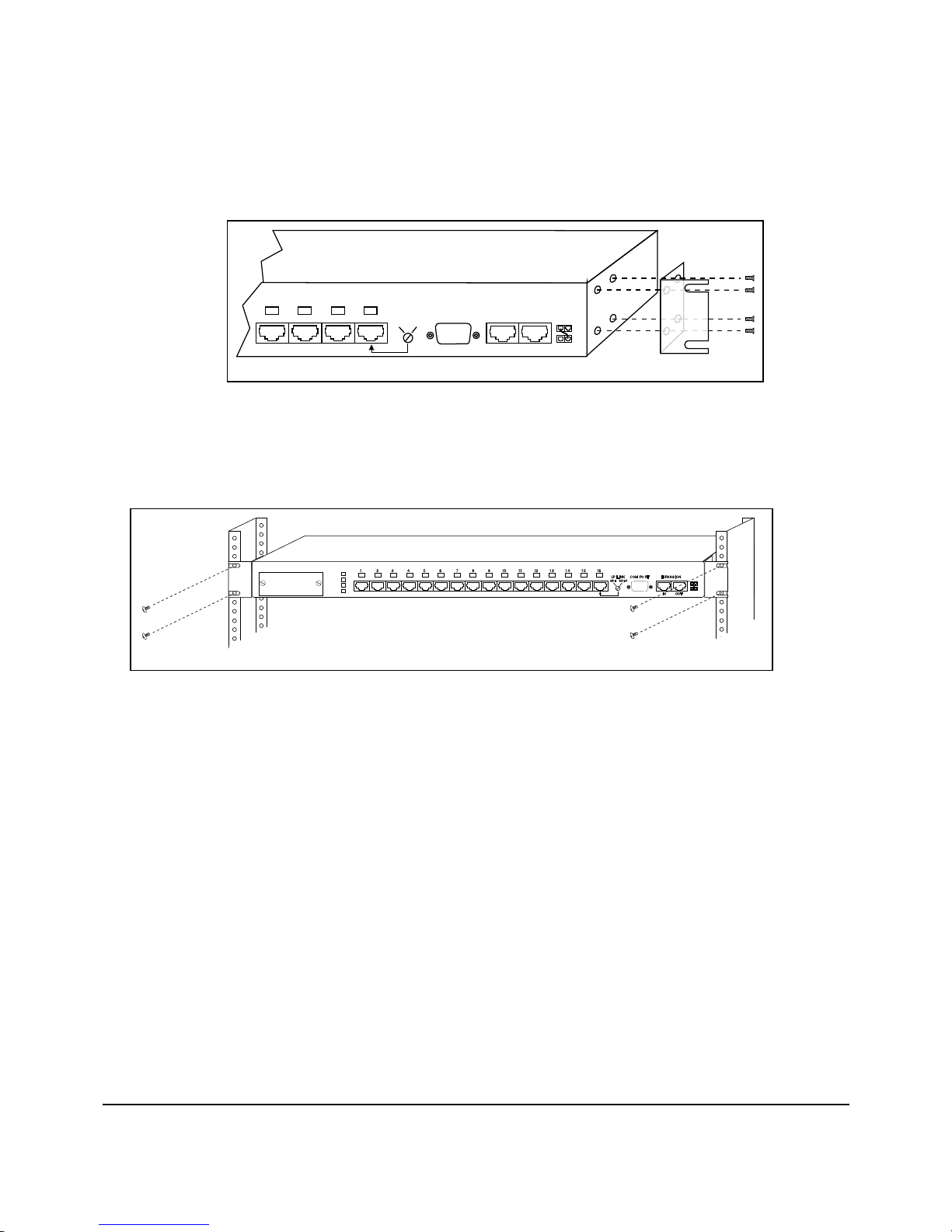
Rack-Mounting the Repeater
To mount the repeater in a rack, use the supplied installation kit. This kit
includes two side mounting brackets and eight screws to secure the brackets. To
attach the brackets, position them as shown in Figure 3-1. Then secure the
brackets with the screws supplied with the mounting kit.
Netelligent 2008/2016 10Base-T Repeater User Guide
Page 28
. . . . . . . . . . . . . . . . . . . . . . . . . . . . .
3-2 Installing the Repeater
13 14 15 16
XXX
MDI MDI-X
COM PORT
Figure 3-1. Attaching the Mounting Brackets
After you attach both mounting brackets, position the bracket slots over the
desired holes on the rack (Figure 3-2). Then insert and tighten the
mounting screws.
1 2 3 4 5 6 7 9 10 11 12 13 14 15 168
PWR
Media Expansion
SEG
COL
Port
MEP
XXXXXXXXXXXXXXX
Figure 3-2. Positioning the Repeater in a Rack
Installing an Alternate Media
EXPANSIONUP LINK
IN OUT
UP LINK
MDI MDI-X
COM PORT
EXPANSION
IN OUT
Connector
The 10Base-T repeater has a Media Expansion Port (MEP) that lets you install
one of the following three optional Alternate Media Connectors (AMCs,
sold separately):
■
BNC for connecting to a Thinnet backbone (Part No. 267064-001)
■
AUI for connecting to a Thicknet backbone (Part No. 267263-001)
■
Fiber for connecting to a 10Base-FL backbone (Part No. 267265-001)
Page 29

. . . . . . . . . . . . . . . . . . . . . . . . . . . . .
3-3
NOTES:
The MEP is the 17th logical port on the repeater.
Link test is available for the fiber optic AMC (hardware is always enabled, but
firmware can effectively disable link test), but not for the AUI or BNC AMCs.
Optional Alternate Media Connectors
(Thinnet)
Figure 3-3.
Optional Alternate Media Connectors
Setting Jumpers for a BNC AMC
If you install a BNC AMC, but do not connect a cable, you must set the
connector board jumper to disable the port. You can also use an external
terminator on this port. If you use a terminator, set the jumper to ON for
future connections.
NOTE: If there is no connection or external terminator at the BNC port, the jumper
must be set to OFF; otherwise, excessive collisions will occur and adversely affect
network performance.
Figure 3-4 shows the AW1 jumper settings.
AUI ConnectorBNC Connector
Fiber Connector
(10BASE-FL)
Netelligent 2008/2016 10Base-T Repeater User Guide
Page 30

. . . . . . . . . . . . . . . . . . . . . . . . . . . . .
3-4 Installing the Repeater
ON
Figure 3-4. AW1 Jumper Settings for a BNC AMC
Inserting the AMC
To insert an AMC, follow these steps:
1. Disconnect the repeater from power.
2. Remove the cover plate from the Media Expansion Port on the repeater's
front panel.
3. Insert the AMC through the Media Expansion Port hole and carefully
push the 20-pin male connector into the MEP socket on the repeater
motherboard until the AMC is secure.
AW1
Disabled
BNC
OFF
BNC
Enabled
(Default)
Page 31

. . . . . . . . . . . . . . . . . . . . . . . . . . . . .
3-5
20-Pin Male
MEP Socket
Connector
Motherboard
Figure 3-5. AMC Installation (Side View)
4. Tighten the screws on the AMC's faceplate.
Connecting Twisted-Pair Cable
Each 10Base-T port on the repeater can accept a standard 4-wire twisted-pair
(UTP or STP) cable that ends with an RJ-45 connector. These ports can support
cable lengths up to 100 meters (328 feet).
To attach twisted-pair cable, plug one of the RJ-45 connectors into the selected
port on the repeater. Connect the other RJ-45 connector into a
10Base-T-equipped workstation.
1 2 3 4 5 6 7 9 10 11 12 13 14 15 168
PWR
Media Expansion
Port
SEG
COL
MEP
XXXXXXXXXXXXXXX
Alternate Media Connector
COM PORT
UP LINK
MDI MDI-X
EXPANSION
IN OUT
Figure 3-6.
Connecting Twisted Pair Wiring
10Base-T-Equipped
Workstation
Netelligent 2008/2016 10Base-T Repeater User Guide
Page 32

. . . . . . . . . . . . . . . . . . . . . . . . . . . . .
3-6 Installing the Repeater
Interconnecting Repeaters
Up to ten repeaters can be interconnected to form one logical repeater that
supports up to 80 Ethernet ports for the 8-port repeater and up to 160 Ethernet
ports for the 16-port repeater. Each repeater can be isolated from the rest of the
repeaters to reside on its own segment. See the “Segmenting Repeaters” section
of this chapter.
Compaq's unique Extended Repeater Architecture (ERA) allows for greater
distances between interconnected repeaters (up to 250 feet, 76.22 meters total).
ERA provides both Ethernet connectivity and inter-repeater communication.
Inter-repeater communication is a management protocol where data is
transferred from one repeater to the next and then repeated until it reaches the
destination repeater. This minimizes signal reflection at extended distances and
also provides a stack order and status signal to indicate the physical bottom
repeater in the stack. ERA also provides automatic detection of powered down
repeaters so that signals will pass through (bypass) those repeaters.
Repeater Expansion Port
The repeater has two Repeater Expansion Ports: the IN port and the OUT port.
Repeaters are interconnected via these ports using a standard, eight-wire (four
twisted pair) Category 3 (or higher) UTP/STP repeater expansion cable that
ends in standard RJ-45 plugs. One 6-inch (15 cm) Category 3 expansion cable
is supplied with the repeater.
To connect one repeater to an adjacent repeater in the stack, connect the lower
repeater's RJ-45 EXPANSION OUT port to the upper repeater's EXPANSION
IN port, as show in Figure 3-7.
Page 33

. . . . . . . . . . . . . . . . . . . . . . . . . . . . .
3-7
Repeater 1
Repeater 2
16
16
MDI MDI-X
MDI MDI-X
COM PORT
COM PORT
EXPANSIONUP LINK
IN
EXPANSIONUP LINK
IN OUT
Repeater Expansion Cable
(Standard Cat 3 or Higher UTP/STP)
OUT
Figure 3-7. Connecting Repeaters via Repeater Expansion Ports
NOTE:
When you add a repeater to a stack, connect the cable to the repeater you
add before you connect it to the repeater in the existing stack. For example, if you
add a repeater to the top of a stack, connect the cable to the IN port of the added
repeater. Then connect the other end of the cable to the OUT port of the existing
repeater in the stack. Do not leave cables connected at only one end. Doing so
reduces performance. The pin-outs of the IN and OUT ports are shown below.
Table 3-1
IN Port Pinouts
Symbol Pin No. Function Description
10B2_DATA 1 In/Out 10B2 Ethernet bus data
10B2_GND 2 In/Out 10B2 Ethernet bus ground
RXDB+ 3 In/Out Serial data negative lower repeater
SHARE_GND 4 Gnd Shared ground
XDOWN 5 In External bottom status indicator
RXDB 6 In/Out Serial data positive lower repeater
SHARE+12 7 Pwr Shared +12V
SHARE_GND 8 Gnd Shared gnd
Netelligent 2008/2016 10Base-T Repeater User Guide
Page 34

. . . . . . . . . . . . . . . . . . . . . . . . . . . . .
3-8 Installing the Repeater
Table 3-2
OUT Port Pinouts
10B2_DATA 1 In/Out 10B2 Ethernet bus data
10B2_GND 2 In/Out 10B2 Ethernet bus gnd
TXDB+ 3 In/Out Serial data negative upper repeater
XUP 4 In External top status indicator
SHARE+12 5 Pwr Shared +12V
TXDB 6 In/Out Serial data positive upper repeater
SHARE+12 7 Pwr Shared +12V
SHARE_GND 8 Gnd Shared ground
Page 35

. . . . . . . . . . . . . . . . . . . . . . . . . . . . .
3-9
Multi-Floor Configuration
The expansion capability provided by Extended Repeater Architecture makes
the repeater ideal for multi-floor network configurations that require repeaters
on each floor (Figure 3-8).
Acme Building
250
Feet
Figure 3-8.
10th Floor
9th Floor
8th Floor
7th Floor
6th Floor
5th Floor
4th Floor
3rd Floor
2nd Floor
1st Floor
MEDIA EXPANSION
MEDIA EXPANSION
MEDIA EXPANSION
MEDIA EXPANSION
MEDIA EXPANSION
MEDIA EXPANSION
MEDIA EXPANSION
MEDIA EXPANSION
MEDIA EXPANSION
MEDIA EXPANSION
PORT
PORT
PORT
PORT
PORT
PORT
PORT
PORT
PORT
PORT
Multi-Floor Configuration
PWR
SEG
COL
MEP
PWR
SEG
COL
MEP
PWR
SEG
COL
MEP
PWR
SEG
COL
MEP
PWR
SEG
COL
MEP
PWR
SEG
COL
MEP
PWR
SEG
COL
MEP
PWR
SEG
COL
MEP
PWR
SEG
COL
MEP
PWR
SEG
COL
MEP
71 161512 13 141110986542 3
71
71 161512 13 1411109865423
71
71
71 16
71 161512 13 1411109865423
71
71 161512 131411109865423
71
13 141110986542 3
13 1411109865423
13 1411109865423
12 13 1411109865423
13 14
109865423
12
11
13 1411109865423
UP LINK EXPANSION
161512
UP LINKTMEXPANSION
UP LINK
161512
UP LINK
161512
UP LINK
15
UP LINK
UP LINK
16
15
UP LINK
UP LINK
161512
UP LINK
COM PORT
COM PORT
COM PORT
COM PORT
COM PORT
COM PORT
COM PORT
COM PORT
IN OUT
IN
EXPANSION
IN
EXPANSION
IN OUT
EXPANSION
IN
EXPANSION
IN OUT
EXPANSIONCOM PORT
IN OUT
EXPANSION
IN OUT
EXPANSION
IN
EXPANSIONCOM PORT
IN
These repeaters reside
Segment 1
OUT
OUT
TM
TM
OUT
TM
TM
TM
TM
OUT
TM
OUT
Segment 2
Isolated
Segment 1
on Segment 1 via the
hub expansion cable
These 64 ports are
isolated from Segment
1 and interconnected
via the 16th port
uplink feature
Floors 1 through
4 are located on
Segment 1
Netelligent 2008/2016 10Base-T Repeater User Guide
Page 36

. . . . . . . . . . . . . . . . . . . . . . . . . . . . .
3-10 Installing the Repeater
CAUTION: Avoid any large differences in AC grounding potentials between
repeaters in the same stack (for example, interconnected repeaters installed
in different buildings). To guarantee operation of the repeaters, AC power
sources for the repeaters in the stack must meet the AC voltage differential
of 1Vrms or less between chassis ground of any repeater in the stack. Large
differences in grounding potentials can damage the repeaters and create a
safety hazard.
Setting the Uplink Switch
The uplink switch lets you cascade repeaters by connecting the 16th RJ-45 port
on one 16-port repeater (or the 8th RJ-45 port on one 8-port repeater) to any RJ45 port on another repeater without the need for special crossover cables. The
default setting for the switch is MDI-X (Media Dependent Interface-Reversed
that is, standard repeater port). To change the position of the switch, use a
small, slotted screwdriver, or a similar tool, to set the switch to the desired
position.
Uplinkable
"OUT" Port
Figure 3-9
UP LINK
MDI MDI-X
16
. Uplink Switch
MDI MDI-X
COM PORT
Standard
"IN" Repeater Port
(Default)
EXPANSIONUP LINK
IN OUT
Page 37

. . . . . . . . . . . . . . . . . . . . . . . . . . . . .
3-11
Segmenting Repeaters
Segmentation divides networks into segments, or smaller networks, of fewer
users. These segments maintain separate collision domains, where fewer users
compete for bandwidth, thereby reducing collisions and increasing
network throughput.
Segmentation of repeaters is accomplished by internally isolating a repeater that
is interconnected to other repeaters via the Repeater Expansion Ports. You can
isolate any repeater in a stack by setting the SNMP variable that isolates a
repeater (nw2BkplNum=6) or by using VT100. When you isolate a repeater, it
occupies its own collision domain and is separate from the collision domain of
the repeaters that are still connected to the backplane. Isolating repeaters lets
you create up to 10 separate collision domains in a 10-repeater stack.
NOTE:
You can view only the stack table for isolated repeaters. For complete
management, you must use a router or bridge to ensure proper connectivity. See
Chapter 4, “Administration and Management” for more information.
In Figure 3-10, Repeaters 1 through 3 are isolated from the other repeaters and
form Collision Domain 1. They are also cascaded together via the uplink switch
and standard twisted-pair cables. See the “Setting the Uplink Switch” section in
this chapter. Repeaters 4 and 5 are not isolated and form Collision Domain 2.
Netelligent 2008/2016 10Base-T Repeater User Guide
Page 38

. . . . . . . . . . . . . . . . . . . . . . . . . . . . .
3-12 Installing the Repeater
External Connections via Uplink Port 16
of Repeaters 2 and 3 to Ports 15 and 14 of Repeater 1
1 2 3 4 5 6 7 9 10 11 12 13 14 15 168
PWR
SEG
COL
MEP
PWR
SEG
COL
MEP
PWR
SEG
COL
MEP
PWR
SEG
COL
MEP
PWR
SEG
COL
MEP
Isolated
Collision Domain 1
Collision Domain 2
Media Expansion
Port
Media Expansion
Port
Media Expansion
Port
Media Expansion
Port
Media Expansion
Port
Figure 3-10. Example of Segmentation
XXXXXXXXXXXXXXX
1 2 3 4 5 6 7 9 10 11 12 13 14 15 168
XXXXXXXXXXXXXXX
1 2 3 4 5 6 7 9 10 11 12 13 14 15 168
XXXXXXXXXXXXXXX
1 2 3 4 5 6 7 9 10 11 12 13 14 15 168
XXXXXXXXXXXXXXX
1 2 3 4 5 6 7 9 10 11 12 13 14 15 168
XXXXXXXXXXXXXXX
UP LINK
MDI MDI-X
UP LINK
MDI MDI-X
UP LINK
MDI MDI-X
UP LINK
MDI MDI-X
UP LINK
MDI MDI-X
COM PORT
COM PORT
COM PORT
COM PORT
COM PORT
EXPANSION
IN
EXPANSION
IN
EXPANSION
IN OUT
EXPANSION
IN
EXPANSION
IN OUT
OUT
Repeater 1
Repeater 2
OUT
Repeater 3
Repeater 4
OUT
Repeater 5
NOTES:
The repeaters do not need to be physically adjacent to one another to be in the
same collision domain.
If the combined length of the repeater expansion cables in a stack exceeds 150
feet (45.7 m), the stack is considered as two repeater hops. The IEEE 802.3
specification states four as the maximum number of repeater hops between
stations on a network.
If a repeater in a stack is powered off or hot-swapped, the remaining repeaters
take a moment to merge together. During this time, an SNMP manager may see
the stack as two or more substacks. When the bottom repeater of a stack or
substack
group map change trap
detects a change in the stack size, the repeater's SNMP agent issues a
. After the remaining repeaters merge, the SNMP
manager sees the repeaters as a single stack.
Page 39

. . . . . . . . . . . . . . . . . . . . . . . . . . . . .
3-13
Backup Port
Any port on the repeater can function as a backup port for another port on the
same repeater. This feature is useful for mission-critical applications (for
example, order-entry workstations connected to a file server). About every 5
seconds, the repeater monitors the status of the primary port. If the port has lost
its link test or has been autopartitioned by the hardware, the repeater enables the
backup port and sends a health state trap to each management station contained
in its IP and IPX trap tables.
Figure 3-11 shows a file server with two network interface cards (NICs)
connected to two ports on a repeater. In this example, Port 1 is the primary port
and Port 2 is the backup port.
File Server
Figure 3-11.
Series 2000 Snappable™Hub
NIC 1
NIC 2
Series 2000 Snappable™Hub
Series 2000 Snappable™Hub
Backup Port Example
NOTES:
If the backup port fails, the repeater does not re-enable the primary port.
When the backup port is enabled, the repeater prevents the primary port from
automatically being re-enabled. To re-enable the primary port, you must use an
SNMP network manager to change the backup port status.
Media Expansion
Port
Media Expansion
Port
Media Expansion
Port
Primary Port
Backup Port
1 2 3 4 5 6 7 9 10 11 12 13 14 15 168
PWR
SEG
COL
MEP
XXXXXXXXXXXXXXX
1 2 3 4 5 6 7 9 10 11 12 13 14 15 168
PWR
SEG
COL
MEP
XXXXXXXXXXXXXXX
1 2 3 4 5 6 7 9 10 11 12 13 14 15 168
PWR
SEG
COL
MEP
XXXXXXXXXXXXXXX
UP LINK
MDI MDI-X
UP LINK
MDI MDI-X
UP LINK
MDI MDI-X
COM PORT
COM PORT
COM PORT
EXPANSION
IN OUT
EXPANSION
IN
EXPANSION
IN OUT
TM
Repeater 1
TM
Repeater 2
OUT
TM
Repeater 3
Netelligent 2008/2016 10Base-T Repeater User Guide
Page 40

. . . . . . . . . . . . . . . . . . . . . . . . . . . . .
3-14 Installing the Repeater
Connecting Power
Follow these steps to connect the repeater to power:
1. Plug the power cord into the power connector on the back of
the repeater.
2. Insert the three-pronged plug on the power cord into a non-switched,
grounded power outlet on a wall, a power strip, or a grounded
extension cord.
Power Cord Connector
Figure 3-12.
NOTE:
3. When you plug in the power cable, verify that the repeater performs the
self test (described in the following section) to confirm that the repeater is
operating correctly.
To power down the repeater, disconnect the male connector from the wall outlet
or power strip. Do not disconnect the female connector from the repeater to
power down the repeater because it is not a tested disconnect.
Connecting the Power Cord
The power outlet should be near the repeater and easily accessible.
Page 41

. . . . . . . . . . . . . . . . . . . . . . . . . . . . .
3-15
Power-On Self Test and Initialization
When power is applied to the repeater, it performs a Power-On Self Test
(POST) and initialization. During the POST, the port status LEDs on the
repeater display the following sequence:
■
Odd-numbered LEDs flash green, even-numbered LEDs are OFF
■
Even-numbered LEDs flash green, odd-numbered LEDs turn OFF
■
Odd-numbered LEDs flash yellow, even-numbered LEDs turn OFF
■
Even-numbered LEDs flash yellow, odd-numbered LEDs turn OFF
After the above sequence, the SEG, COL, and MEP LEDs flash green, then
yellow, and then turn OFF. When the repeater successfully completes the
POST, it performs the BOOT initialization followed by the Flash initialization.
The PWR LED shows the current Power/POST/initialization status as follows:
OFF No power to the repeater or a hardware failure
■
Yellow POST/initialization in progress or operating out of boot code
■
Flashing Yellow POST failed or the repeater is faulty
■
Green POST was successful and initialization is complete. repeater is
■
operating out of Flash and is fully functional.
NOTE: The port activity LEDs do not function until the PWR LED turns green.
Non-Volatile Memory Check
A test is performed on the NVRAM during the initialization of the flash. If the
test detects an error, the user is notified in the following ways:
■
The PWR (power) LED toggles green, yellow, green, yellow (1 second
on each color) and then lights steady green. (This occurs only
during initialization.)
■
A message is sent to the RS-232 port indicating an error condition. (This
occurs only during initialization.)
Netelligent 2008/2016 10Base-T Repeater User Guide
Page 42

. . . . . . . . . . . . . . . . . . . . . . . . . . . . .
3-16 Installing the Repeater
■
The MIB variable nw2NVRAMStatus is set to error(2).
These messages only indicate a NVRAM malfunction. The repeater and
management functions are still operational. Only the configuration parameters
in NVRAM are re-initialized to their defaults.
Page 43

. . . . . . . . . . . . . . . . . . . . . . . . . . . . .
4-1
Chapter 4
Administration and
Management
This chapter contains information about SNMP management, out-of-band
management using SLIP, error and fault processing, Flash updates, and other
information related to the firmware for the Netelligent 2008 and
2016 repeaters.
Boot and Runtime Overview
The Netelligent 2008/2016 repeater firmware is divided into two distinct
firmware blocks:
■
Boot
Boot
Runtime
■
Runtime
Boot provides these basic features:
■
POST (Power On Self Test)
■
BOOTP/TFTP
■
Verification of valid Runtime
■
Autopolarity Reversal for UTP ports
■
XMODEM (Configuration File and Runtime upgrades)
NOTE: Boot cannot be upgraded via TFTP or XMODEM.
Runtime is field upgradable via a firmware download using XMODEM or
TFTP. Runtime provides these basic features:
■
VT100 (Telnet and SLIP)
Netelligent 2008/2016 10Base-T Repeater User Guide
Page 44

. . . . . . . . . . . . . . . . . . . . . . . . . . . . . .
4-2 Administration and Management
❏
In-band via Telnet
❏
Out-of-band via Telnet /SLIP
❏
Out-of-band via VT100; using ANSI terminal emulation
■
SNMP
❏
In-band via IP
❏
In-band via IPX
❏
Out-of-band via SLIP
■
LED Management
■
Backup Ports
■
In-band management over IPX with SMMP and SNMP
■
Intrusion detection with the option to configure security
■
BOOTP/RARP
■
InterHub Communication
■
Autopolarity Reversal for standard UTP Ports
■
Port Management
Configuring the Repeater
During the Boot Process
You can configure the repeater during the boot process in the following
three ways:
■
Via an XMODEM text configuration file
■
Via a BOOTP server
■
Via a reverse ARP (RARP) server
Page 45

. . . . . . . . . . . . . . . . . . . . . . . . . . . . .
4-3
XMODEM Text Configuration File
You can set the repeater IP address during the boot process by downloading a
text configuration file using the XMODEM protocol. This requires a PC with a
serial port, a text editor (to change the IP address), an XMODEM file transfer
program, and a null modem cable. You can substitute a pair of modems with
modem cables for the null modem cable if you want to set the IP address
remotely.
The text configuration file is used in conjunction with a second binary Flash
image file to update the Flash in the repeater (see the section “XMODEM
Implementation” in this chapter). The text file uses acronyms to simplify the
firmware parsing. The following example configuration file updates the
repeater configuration parameters and prepares the repeater for a firmware
download (i.e., erases the current Flash). This example assumes that the COM
serial port is used for a SLIP connection. If not, the serial IP address and
NetMask should be set to "0.0.0.0".
;SMM16/8 XMODEM Config
;Comment ";" in column 1; Max size=512
;
;"FL=yes" sets IP/NM/GW/WC/SI/SM; no skips
FL=yes
;IP Addr
IP=192.103.93.200
;Net Mask
NM=255.255.255.0
;Default Gateway
GW=192.103.93.139
;Write Community
WC=public
;SLIP IP
SI=192.103.83.200
;SLIP Mask
SM=255.255.255.0
;Flash Version; erases Flash!
FV=8NW1.30
;END
The valid values for each field are shown in the following table.
Netelligent 2008/2016 10Base-T Repeater User Guide
Page 46

. . . . . . . . . . . . . . . . . . . . . . . . . . . . . .
4-4 Administration and Management
If you want to modify only the repeater configuration parameters (Items 2 to 7)
and not the Flash sectors, comment out or delete Item 8. To comment out a line,
place a semicolon (;) in Column 1. If FL=yes, Items 2 to 7 must be in the text
configuration file.
To update the Flash without updating the repeater configuration parameters, set
FL=no or delete/comment out Items 1 to 7 (i.e., have only the FV line in the
text configuration file).
Item Field Meaning Valid Values/Descriptions
1 FL Update flag “Yes” updates the repeater configuration for items 2 through 7 (all items
must be present); “No” indicates no update.
2 IP Repeater IP Address Any valid IP address (cannot use 255.255.255.255 (broadcast IP)
3 NM IP Net Mask Any valid Net Mask (cannot be 0.0.0.0 or 255.255.255.255); must start
with a “1" in the left bit position (e.g., 128.0.0.0); “1's" in Net Mask must
be contiguous (i.e., proceeding from left to right, once a bit is set to “0",
there can be no more “1" bits (e.g., 255.255.192.0 is contiguous;
255.255.160.0 is NOT contiguous))
4 GW IP Default Gateway Any valid IP Default Gateway address (cannot use 255.255.255.255)
5 WC Write Community
String
6 SI SLIP IP Address Any valid IP address (cannot use 255.255.255.255, broadcast IP); if the
7 SM SLIP Net Mask Any valid NetMask (see Item 3)
8 FV Firmware Version
String
Up to 20 characters (alphanumeric, underscores, spaces); using more than
20 characters causes an error
COM serial port on this repeater is not used for a SLIP connection, set
SI=0.0.0.0".
Non-null value indicates that the firmware will be updated (i.e., erased and
downloaded); comment out (with a semi-colon, “;”) or delete the FV field to
update only the repeater configuration parameters. This field also indicates
the type of repeater (2008 or 2016). For example, 8-port repeaters use
8NWx.xx and 16-port repeaters use NWVx.xx.
Page 47

. . . . . . . . . . . . . . . . . . . . . . . . . . . . .
4-5
Text Configuration Field Values
The firmware parser ignores blank lines at the end of the text configuration file.
If quotation marks enclose the write community string, the parser considers the
marks part of the string. If spaces are embedded in the string, the parser accepts
the first 19 characters, including spaces.
NOTE
: If the text configuration file contains a valid "FV" line, the Flash is erased to
prepare for a Flash Update. See the section “Updating Flash” later in this chapter.
Text Configuration File Rules:
■
The configuration file can be composed with an ASCII text editor (each
line must be terminated with either a "CR/LF" (0x0D/0x0A) pair, a
"CR" or a "LF").
■
The maximum file size is 512 bytes.
■
The maximum line length is 132 bytes.
■
Comments must start with a semicolon (;) in Column 1. The file can
contain any number of comments as long as it does not exceed the
maximum file size and line length.
■
No spaces are allowed before or after the equal sign (=) in each line
(except for a write community string that starts with a space).
■
The acronyms, as well as the yes/no data, can be in upper or lower
case letters.
■
There must be a comment line (e.g., ";END") after the last valid noncomment line (e.g., "FV=8NW1.30"). Most XMODEM
implementations "pad" out the last 128-byte transmit block. The final
comment allows the parser to determine the precise end of the previous
non-comment line (i.e., avoids confusion with the "pad" characters).
■
The firmware version string indicates not only the version number but
also the type of repeater. The 8-port 2008 repeater uses 8NWx.xx and
the 16-port 2016 repeater uses NWVx.xx.
Certain combinations of IP addresses and Net Masks also cause configuration
errors. When the IP address (IP) is logically ANDed with the Net Mask (NM)
the result cannot be equal to the SLIP IP address (SI) logically ANDed with the
SLIP Net Mask (SM).
Netelligent 2008/2016 10Base-T Repeater User Guide
Page 48

. . . . . . . . . . . . . . . . . . . . . . . . . . . . . .
4-6 Administration and Management
The following combination is invalid:
IP =192.103.83.200 SI =192.103.83.201
NM =255.255.255.0 SM =255.255.255.0
========================================
AND=192.103.83.0 AND=192.103.83.0
The following combination is valid:
IP =192.103.93.200 SI =192.103.83.200
NM =255.255.255.0 SM =255.255.255.0
=================== ===================
AND=192.103.93.0 AND=192.103.83.0
If there is any error at all (e.g., parsing error, invalid IP address, more than 20
characters in the write community string), the repeater configuration update
stops without making any updates. Since the serial COM port uses the
XMODEM protocol, it cannot indicate an error. Therefore, the UTP port status
LED's provide error indications. If the configuration file update is successful,
the status LED's flash green-off-green (0.5 second each). If an error is detected,
the status LED's flash orange-off-orange (0.5 second each).
If there is an active SLIP session on the COM serial port, there is a 3-minute
time-out before an XMODEM transfer can begin. When an XMODEM transfer
starts, the repeater disables all interrupts except for the timer. The CPU polls the
COM serial port for activity. Consequently, SNMP requests, as well as normal
repeater processing (e.g., checking for backup ports, updating the status LEDs),
are ignored during XMODEM transfers.
XMODEM Implementation
When the repeater (receiver) is ready to initiate an XMODEM transfer, it issues
a synchronization byte at 10-second intervals to the workstation (sender) to
inform it which type of block error checking method is used (CRC or
checksum). Once the error checking type is established, the repeater uses the
first XMODEM packet to synchronize the transfer and then discards the packet.
This causes the repeater to retransmit the first packet. The retransmission is
invisible to the user except in XMODEM applications that report block errors.
Page 49

. . . . . . . . . . . . . . . . . . . . . . . . . . . . .
4-7
You can use a common terminal emulation program, such as Window's
Terminal or Procomm, to perform XMODEM file transfers. If the program
gives you a choice, use binary XMODEM transfers for both the text
configuration file and the binary Flash image file.
To update either the text configuration file or the binary Flash image file, wait
until a letter “C” appears on the terminal emulation screen before you select the
Upload or Send menu. Otherwise, the terminal emulation screen is blocked and
you cannot see the “C.”
The following sequence of events can help you understand the XMODEM user
interface. This sequence applies to both text configuration file and binary Flash
image file transfers.
1. Determine if an XMODEM transfer is being initiated over a null modem
cable at 9600 baud:
■
Repeater sends a letter “C” and waits 10 seconds for a response.
■
Repeater sends a NAK and waits 10 seconds for a response.
■
Repeater sends a letter “C” and waits 10 seconds for a response.
■
Repeater sends a NAK and waits 10 seconds for a response.
When you see the letter “C” (that is, the repeater already sent the first
sync byte that the sending program already missed), you have 30
seconds to start the file transfer. If the sending PC responds during this
interval, the transfer proceeds.
If no XMODEM transfer starts, the repeater attempts to find a modem at
the following speeds:
■
Repeater sends a 9600 Baud modem initialization string and waits
10 seconds for a response.
■
Repeater sends a 2400 Baud modem initialization string and waits
10 seconds for a response.
■
Repeater sends a 1200 Baud modem initialization string and waits
10 seconds for a response.
■
Repeater sends a 300 Baud modem initialization string and waits 10
seconds for a response.
Netelligent 2008/2016 10Base-T Repeater User Guide
Page 50

. . . . . . . . . . . . . . . . . . . . . . . . . . . . . .
4-8 Administration and Management
If the repeater receives a valid modem response, it knows that a modem
is connected to the COM serial port. The repeater does not know if the
modem is operating at its highest possible baud rate. For example, if the
modem is plugged in just before the 300 Baud initialization string is
issued, the modem remains at 300 Baud. (It is not recommended to
transfer a 180KB Flash image file at 300 Baud if the modem supports a
higher baud rate). Consequently, unless the modem is already connected
at 9600 Baud, the repeater re-issues the 9600 Baud modem initialization
string and then continues to search at each consecutively lower Baud
rate until it detects the highest speed modem supported.
If the repeater does not receive a valid modem response, the connection
algorithm restarts and the repeater firmware reattempts an XMODEM
transfer (Step 1).
2. See if a modem is still attached:
Once a modem connection is established, the repeater checks to see if
the modem is still attached by sending an initialization string every
minute. If the modem does not respond, the connection algorithm
restarts, searching for a null modem cable XMODEM transfer (Step 1).
3. Wait for the modem to go off hook and initiate an XMODEM transfer:
When the repeater's COM serial port modem answers the incoming call,
its Carrier Detect (CD) line is asserted. After the repeater sees an active
CD, it delays 30 seconds and then repeatedly sends the following sync
bytes until an XMODEM transfer starts or CD goes inactive.
■
Repeater sends a C and waits 10 seconds for a response.
■
Repeater sends a NAK and waits 10 seconds for a response.
If CD goes inactive, the repeater checks to see if the modem is still
attached (Step 2).
Page 51

. . . . . . . . . . . . . . . . . . . . . . . . . . . . .
4-9
If you update the repeater firmware with an XMODEM configuration
file while the PWR LED is orange (i.e., while executing from Boot), the
updates take effect when the firmware jumps from the boot sectors into
the Flash sectors (i.e., they will be valid by the time the PWR LED turns
green). If you update the firmware when the PWR LED is already green
(i.e., executing from Flash) and only the configuration parameters are
updated, the updates take effect immediately.
BOOTP Server
On IP networks, you can use a BOOTP server to set the repeater configuration
parameters and download new Flash updates. (See “Updating Flash” in this
chapter.) Every time the repeater initializes its BOOT, it makes a predetermined
number of BOOTP/RARP requests, each of which contains the MAC address
of the requesting repeater. (The number or requests is set in the
nw2BootpRarpRetries MIB variable.) The repeater issues the BOOTP request
simultaneously over both the ETHERNET_II and ETHERNET 802.2 SNAP
frame types and waits a predetermined time interval (set in the
nw2BootpRarpRetryInterval MIB variable) for a response.
If the BOOTP server is active and finds the repeater's MAC address in its
database, it sends the repeater its IP address, IP net mask, and IP default
gateway. If the BOOTP response is valid, the repeater makes no more BOOTP
requests. The repeater uses the BOOTP response to determine the frame type to
be used for IP communications. If the repeater receives no BOOTP response,
the firmware performs the same sequence using RARP requests instead of
BOOTP requests. Shown below is a sample USRBOOTP file. This sample file
also updates the Flash program sectors.
Netelligent 2008/2016 10Base-T Repeater User Guide
Page 52

. . . . . . . . . . . . . . . . . . . . . . . . . . . . . .
4-10 Administration and Management
global.dummy:\
:sm=255.255.255.0:\
:bf=c:\flash\nw8v101.img:
# Next, define different master entries for each subnet. . .
subnet105:\
:tc=global.dummy:gw=192.103.93.139:
# The Hostname contains the firmware version followed by the entire
# MAC Address (including leading zeros). Modify the appropriate entries
# as needed using the following legend:
#
# ht = hardware type
# ha = hardware address
# ip = IP Address for the unit with the above "ha"
# gw = Gateway IP Address
# sm = Subnet Mask
# bf = bootfile name (including path - must be << 64 characters)
# hn = hostname (do not fill in). This entry will cause the hostname
# to be sent as part of the BOOTP Response. This is necessary
# for the unit to TFTP properly. If no TFTP Flash update
# is desired, then remove the "bf=..." and "hn:" lines and the
# continuation slash from the preceding line.
#
# Examples are shown below. Each entry should have a unique hostname.
# The hostname can only contain alphanumeric characters.
8NW110.00.00.79.58.00.22:\
ht=ethernet:\
ha=000079580022:\
ip=192.103.93.10:\
sm=255.255.255.0:\
gw=192.103.93.139:\
bf=c:\flash\8nwv110.img:\
hn:
NWV101000079580026:\
ht=ethernet:\
ha=000079580026:\
ip=192.103.93.11:\
sm=255.255.255.0:\
gw=192.103.93.139:\
bf=c:\flash\nwv130.img:\
hn:
Page 53

. . . . . . . . . . . . . . . . . . . . . . . . . . . . .
4-11
NOTE: This USRBOOTP file is only an example. For information about the
appropriate file for your specific BOOTP server, refer to the BOOTP
server documentation.
If the repeater receives no response for any the BOOTP or RARP requests and
if the repeater already has a valid IP address stored in NVRAM, the NVRAM
IP address is used.
Once in Runtime, if there is not a valid IP address in NVRAM and the
nw2BootpRarpRequests MIB variable is set to doBootpRarp(1), the firmware
loops until it receives a valid IP address. The following information describes
various repeater operations and limitations of the IP address search loop.
■
Every 5 minutes, the repeater makes a BOOTP request. If the repeater
does not receive a BOOTP response within 5 seconds, it makes a RARP
request. If the repeater does not receive a RARP response within 5
seconds, it waits 5 minutes and then re-issues the
BOOTP/RARP requests.
■
The repeater can receive an IPX set request during the 5-minute interval
when it is not making BOOTP/RARP requests. If an IPX set request
occurs during the 10-second BOOTP/RARP period, the repeater ignores
the request (i.e., the request times out).
■
You can use SNMP over IPX to set the repeater's IP address during the
5-minute interval when the repeater is not making BOOTP/RARP
requests If an SNMP over IPX set request occurs during the 10-second
BOOTP/RARP period, the repeater ignores the request (i.e., the request
times out).
■
VT100 can be used at any time.
NOTE: The repeater may periodically disable SNMP requests during the BOOT/RARP
request intervals, reducing network management performance for IPX-only
networks. To prevent this from occurring, either assign an IP address to each
repeater or set the nw2BootpRarpRequests MIB object to noBootpRarp(2), which
disables the periodic BOOTP/RARP requests in Runtime and in Boot if you have
Boot v1.30.
Netelligent 2008/2016 10Base-T Repeater User Guide
Page 54

. . . . . . . . . . . . . . . . . . . . . . . . . . . . . .
4-12 Administration and Management
Reverse ARP Server
On IP networks, you can use a RARP (Reverse Address Resolution Protocol)
server to set the repeater IP address. Every time the repeater completes its
POST, it makes a predetermined number of BOOTP/RARP requests, each of
which contains the MAC address of the requesting repeater. (The number or
requests is set in the nw2BootpRarpRetries MIB variable.) The RARP request
contains the MAC address of the requesting repeater. The repeater issues the
RARP request simultaneously over both the ETHERNET_II and ETHERNET
802.2 SNAP frame types and waits a predetermined time interval (set in the
nw2BootpRarpRetryInterval MIB variable) for a response. If the RARP server
is active and finds the requesting repeater's MAC address in its database, it
sends the repeater its IP address. The repeater uses the response to determine
the frame type to be used for IP communications.
NVRAM Usage
The Netelligent 2008/2016 repeaters have nonvolatile RAM (NVRAM) that
stores parameters that must survive a power failure or CPU reset. The NVRAM
stores the following information:
■
Backup port information (the backup port status is configured during
boot; default = none)
❏
primary port, backup port, and backup state
■
Port names information
❏
Supports port names up to 10 characters in length for each port
(supports 17 ports).
■
SNMP information
❏
IP address (default = 0.0.0.0). If you set the IP address to 0.0.0.0,
there is no valid IP address.
❏
IP network mask (default = 0.0.0.0)
❏
default gateway IP address
❏
sysLocation (RFC1213)
Page 55

. . . . . . . . . . . . . . . . . . . . . . . . . . . . .
4-13
❏
sysName (RFC1213)
❏
snmpEnableAuthenTraps (RFC1213)
❏
nws2WriteProtected (NWS2000 MIB)
❏
nws2WriteCommunity (NWS2000 MIB)
❏
nws2BootpRarpRequests (NWS2000 MIB)
❏
SLIP IP address (default = 0.0.0.0 (none))
❏
SLIP IP network mask (default = none)
❏
IP trap table (10 recipients; default = none)
IP address
SNMP community name
■
General unit level parameters (these parameters are configured
during boot)
❏
backplane (isolated or bussed; default = bussed)
❏
link test disable/enable for each port (default = enabled)
❏
ports disabled (default = enabled)
■
IPX trap table (10 recipients; default = none)
❏
IPX address
❏
SNMP write community name
■
Routing information (5 entries; default = none)
■
Intrusion
❏
MAC address for each of the 17 ports
❏
Intrusion Status (Disabled, Enabled, Tripped) for all 17 ports
❏
Security Password (6 characters)
❏
IPX Frame Type
❏
SAP Disable
❏
IP Frame Type
Netelligent 2008/2016 10Base-T Repeater User Guide
Page 56

. . . . . . . . . . . . . . . . . . . . . . . . . . . . . .
4-14 Administration and Management
■
VT100
❏
VT100 Refresh rate
❏
Modem Initialization string up to 40 characters in length
❏
BOOTP/RARP timeout interval
❏
Maximum retry count for BOOTP/RARP
Runtime Features
The Runtime component of the repeater firmware v1.3 provides a backup port
feature, intrusion protection, and RJ-45 autopolarity reversal.
Backup Port Usage
You can designate a backup port that provides a redundant connection for a
primary port to protect mission-critical applications (e.g., order entry PCs
connected to a file server). The repeater activates the backup port when the
primary port loses link test or is autopartitioned by the hardware. Any port on
the repeater can back up any other port on the same repeater. However, a port
on the repeater cannot back up a port on another repeater.
During normal operation, the backup port is disabled. About every 5 seconds,
the repeater monitors the status of the primary port. If the primary port loses its
link test (e.g., the NIC loses power) or has been autopartitioned by the
hardware, the repeater disables the primary port, enables the backup port, and
sends an SNMP "health state trap" to each management station contained in its
IP and IPX trap tables. The primary port remains disabled to prevent it from
being incorrectly re-enabled. If the backup port fails, the repeater does not reenable the primary port.
To re-enable the primary port after a backup port has been activated, you must
use an SNMP network manager to change the backup port status.
The repeater does not monitor backup ports during BOOTP/RARP initialization
and downloading of new firmware.
Page 57

. . . . . . . . . . . . . . . . . . . . . . . . . . . . .
4-15
Intrusion Protection
Firmware v1.30 supports intrusion protection, which provides a method of
preventing unauthorized access to the network. Intrusion protection allows any
SNMP manager to configure one MAC address per port and to enable or
disable intrusion protection on a per port basis.
NOTE
: Do not set intrusion protection on an uplink port that receives multiple MAC
addresses. Otherwise, the repeater disables the port.
Follow these steps to enable intrusion protection for a port:
1. Use an SNMP MIB browser to set the authorized MAC address in the
nw2IntrusionPortMACAddress or nw2IntrusionPortMACAddressStr
MIB variable.
2. Set the nw2IntrusionPortStatus MIB variable to enable(2).
Once you configure intrusion for a port, the repeater's firmware monitors the
port for intruders. If the port detects an unauthorized MAC address, the repeater
partitions the port, i.e., sets nw2IntrusionPortStatus to tripped(3)and generates a
Novell Health State trap in the trap table. To restore the port after it detects an
intruder, use an SNMP manager to set the rptrBasPortAdminState MIB variable
(located in the Novell MIB) to enable(2).
Changing the Status of a Port
The SNMP manager lets you change the intrusion status of a port via the
nw2IntrusionPortStatus MIB variable. To do so, verify that the
nw2SecurityStatus MIB variable is set to disable(1). Then set the
nw2IntrusionPortStatus MIB variable to disable(1), enable(2), or tripped(3).
NOTE
: If the SNMP manager tries to change the settings of nw2IntrusionPortStatus
when nw2SecurityStatus is set to enable(2), a PDU error occurs.
Netelligent 2008/2016 10Base-T Repeater User Guide
Page 58

. . . . . . . . . . . . . . . . . . . . . . . . . . . . . .
4-16 Administration and Management
Security
The security feature provides further network security by restricting access to
the nw2IntrusionPortStatus and nw2IntrusionPortMACAddress MIB variables,
which prevents any changes to the intrusion table. To use the security feature,
you must use an SNMP manager that supports security.
RJ-45 Autopolarity Reversal
Autopolarity reversal is a port-level programmable feature provided with Boot
v1.30. When enabled, autopolarity reversal can automatically invert the polarity
of the port to correct a wiring error. Boot v1.30 enables Autopolarity reversal
before it starts its BOOTP/RARP sequence. If Runtime v1.30 is running with
an older version of Boot, it enables Autopolarity reversal when the Boot
sequence completes and Runtime is executing. Resetting the repeater disables
Autopolarity reversal.
Supported Frame Types
The Netelligent 2008 and 2016 repeaters support the following frame types:
■
802.3 RAW: IPX
■
802.2 (TYPE II): IPX
■
802.2 SNAP: IPX and IP
■
Ethernet_II: IPX and IP
Supported Protocols
The repeater supports both the IP and IPX protocol stacks for SNMP
management. The VT100 management interface is also supported over the
TCP/IP stack. All pertinent frame types are supported for each of these
protocol stacks.
Page 59

. . . . . . . . . . . . . . . . . . . . . . . . . . . . .
4-17
TCP/IP Support
The repeater supports SNMP over IP. This requires the full implementation of
the UDP/IP protocol stack which includes address resolution protocols (ARP,
RARP, and BOOTP), a control and error message protocol (ICMP), and IP
fragmentation (supported to a maximum packet size of 1520 bytes).
For greater management flexibility, the IP stack is supported over both
ETHERNET_II (default) and 802.2 SNAP header with 802.3 frame types.
BOOTP, RARP, and TFTP packets originate from the repeater. For BOOTP
and RARP, both 802.2 SNAP over 802.3 and ETHERNET_II frame types are
sent consecutively. If the repeater receives a response, it uses the frame type of
the response to set the nw2IPFrameType MIB variable (stored in NVRAM). All
IP reception and transmission use the same frame type. To allow the repeater to
route any IP traffic, the frame type must also match the default gateway's frame
type. The repeater supports only one frame type (802.2 SNAP or
ETHERNET_II SNMP) per IP network.
IPX Support
The repeater performs the follow steps to determine the IP frame type to use:
1. If a response is received from a BOOTP or RARP server, use the frame
type of the received packet.
2. If no response is received from a BOOTP or RARP server, use the value
stored in NVRAM for the frame type.
3. If no value is stored in NVRAM, use the default value of
ETHERNET_II.
4. You can change the frame type at any time by setting the
nw2IPFrameType MIB variable through the VT100 interface or SNMP.
The repeater supports IPX over ETHERNET_II, 802.3 RAW, 802.2 header
with 802.3, and 802.2 SNAP header with 802.3 frame types. The default frame
type used by the repeater is 802.2 over 802.3.
Netelligent 2008/2016 10Base-T Repeater User Guide
Page 60

. . . . . . . . . . . . . . . . . . . . . . . . . . . . . .
4-18 Administration and Management
SNMP requests and responses, RIP (requests and responses), IPX diagnostics,
and Compaq’s propriety protocol are all packets that do not originate from the
repeater but use IPX. A management station sends these packets to the repeater
and waits for the response. The SNMP management agent receives the packet
and sends it back using the same frame type and IPX network number that was
used to send the packet. The repeater supports all IPX frame types for response
type traffic.
The repeater originates packets for SNMP traps and RIP/SAP broadcasts.
Therefore, the repeater must know the IPX frame type and network number to
be able to transmit the packets. This requires the use of MIB variables, one of
which is the nw2IPXFrameType variable.
The repeater performs the following steps to determine the IPX frame type to
use on packets it originates:
1. Use the value stored in NVRAM for the frame type.
2. If no value is stored in NVRAM, use the default value of 802.2 over
802.3.
3. You can change the frame type at any time by setting the
nw2IPXFrameType MIB variable through the VT100 interface
or SNMP.
The repeater determines the IPX network numbers for SNMP traps through the
MIB variables that indicate the IPX trap receiver addresses. The repeater learns
IPX network numbers for RIP and SAP broadcasts by analyzing the RIP
broadcasts that IPX routers send over the network. If the repeater cannot learn
the network number through the network traffic, it uses the default network
number 0.
IP / IPX Autodiscovery
The repeater supports both IP and IPX autodiscovery mechanisms. Therefore,
standard management platforms such as Novell's ManageWise and HP
OpenView can autodiscover the repeater.
Page 61

. . . . . . . . . . . . . . . . . . . . . . . . . . . . .
4-19
IPX Autodiscovery
The repeater supports Novell IPX autodiscovery through its HMI-compliance
mechanism. IPX autodiscovery supports the SAP, RIP, and IPX diagnostics
protocols. Using SAP, the repeater advertises itself as HMI compliant. When
Novell's NMS or ManageWise initiates autodiscovery, it produces bindery
requests through NCP to a NetWare server. This allows NMS to obtain the
internal network number of the HMI-compliant device and, through RIP, obtain
the MAC address and other necessary information to start SNMP over IPX
communication. IPX diagnostics are implemented only to support the
NetExplorer server. This protocol is not directly involved with the NMS
autodiscovery algorithm, but is used to update the NMS database with the
current network configuration.
Novell servers keep a cache of the services available on the network. The cache
has an aging mechanism, so services such as the repeater's HMI services can be
deleted. To prevent this deletion, the repeater broadcasts its services via SAP
every 55 seconds. You can disable or enable these SAP broadcasts through a
MIB variable. The default setting is enabled.
IP Autodiscovery
The repeater supports a generic IP autodiscovery used by many leading SNMP
platforms (e.g. HP OpenView, SunNet Manager, and NetView 6000). IP
autodiscovery uses the ARP cache of gateways or routers present on the
network. The gateways and routers have ARP cache aging mechanisms that
refresh the cache and remove undetected addresses, making it necessary to
periodically update the cache for IP autodiscovery. If there is not enough
SNMP traffic, addresses may be deleted from the cache. The repeater
periodically transmits an ICMP ping to its IP default gateway. You can use
either SNMP or VT100 management interfaces to change a MIB variable that
matches the rate of ping transmissions with the IP gateway's cache aging timer.
This guarantees that the gateway's ARP cache is current and valid. If no default
IP gateway is set up, the repeater does not transmit the pings and IP
autodiscovery is not guaranteed.
A MIB variable lets you disable or enable IP autodiscovery. The repeater
retains in NVRAM all settings for IP autodiscovery enable and ping timer
MIB variables.
Netelligent 2008/2016 10Base-T Repeater User Guide
Page 62

. . . . . . . . . . . . . . . . . . . . . . . . . . . . . .
4-20 Administration and Management
IPX-Based Smart Module
Management Protocol
In addition to SNMP over IP and IPX, the repeater supports the IPX-Based
Smart Module Management Protocol (SMMP). This proprietary, IPX-based
protocol is designed to manage Compaq repeaters.
Fault Processing
The repeater responds to fault conditions in the following ways:
Powered Down Repeater: After power is removed from the repeater,
■
the SNMP network manager re-synchronizes the inter-hub
communications and ignores (does not detect) the repeater.
Hot Swapping a Repeater: When a repeater is removed from or added
■
to an existing stack, an inter-hub communication error occurs. After the
SNMP network manager re-synchronizes inter-hub communications, is
sees the new stack configuration.
Repeater Hardware Failure: If the top or bottom repeater has a
■
hardware failure (for example, the CPU fails), the SNMP network
manager re-synchronizes inter-hub communications and sees a shorter
stack. If one of the middle repeaters fails, the SNMP network manager
sees two sub-stacks (one stack above and one stack below the failed
repeater). The sub-stacks can be merged by cabling around the failed
repeater or by powering off the defective repeater (if the bypass circuitry
has not failed).
Powering a Repeater Off and Back On: For 5 seconds to 170 minutes
■
(maximum number BOOTP/RARP retries and the maximum
BOOTPP/RARP time out) after a repeater has had its power cycled, it is
unable to participate in the inter-hub communications. During this
interval, the repeater performs a POST and makes BOOTP and RARP
requests. Until these tasks are complete, the SNMP network manager
sees the same results that occur when there is a repeater hardware failure
(that is, a shorter stack or two sub-stacks).
Page 63

. . . . . . . . . . . . . . . . . . . . . . . . . . . . .
4-21
Compaq-Specific Parameters
This section contains parameters that are specific to the Netelligent 2008 and
2016 repeaters.
Ethernet Node Address Range: Compaq has initially reserved 262,144
■
physical node addresses (i.e., MAC addresses) for the 2008 and 2016
repeaters. Each repeater must have a unique node address. The address
consists of six bytes. The first three bytes are fixed, while the last three
bytes are unique for each repeater. Shown below is the node address
range in an MSB (most significant bit) hex form. The three-byte VV VV
VV field starts with 58 00 00 and increments by one up to a maximum
value of 5B FF FF.
00 00 79 VV VV VV
Enterprise Number: The MIB II enterprise number is 215.
■
sysObjectID: The system object ID contains the following:
■
Using IPX
1.3.6.1.4.1.215.1.1.4.2.6
sysDescr: The system description strings contain the product name.
■
SAP ID: A hex 05A9 SAP ID is used to advertise the repeater service.
■
Novell assigns this SAP ID to Compaq Computer Corporation.
Well Known IPX Socket ID: The well known IPX socket ID used for
■
the IPX-Based Smart Module Management Protocol is hex 8468.
Novell assigns this socket IP to Compaq Computer Corporation.
You can set the repeater’s IP address, IP net mask, and IP default gateway using
the DOS-based SETIP.EXE utility. The network must support IPX between the
workstation and the repeater (that is, IPX routers are required between
segments). To set the address, you must know the repeater's MAC address and
its Novell network number.
You can use Compaq Netelligent Management Software to set the SNMP write
community string. Be sure you set the write community for the bottom repeater
in the stack so that the new string propagates through the stack and is not
overwritten with the prior setting.
Netelligent 2008/2016 10Base-T Repeater User Guide
Page 64

. . . . . . . . . . . . . . . . . . . . . . . . . . . . . .
4-22 Administration and Management
NOTE: These utilities require a PC with an Ethernet NIC, a NIC driver, and an IPX
protocol stack.
Using SNMP (over IP and over IPX)
Once you set the IP address for any repeater in a Netelligent 2008/2016 repeater
stack, you can set the IP addresses for the remaining repeaters by making
SNMP over IP requests. You must use the DOS-based SETIP.EXE utility to set
the IP address of the initial repeater (see "Using IPX” in this chapter). An
SNMP network manager can set/update the IP addresses (and other
configurations parameters) for each of the repeaters in a stack by modifying the
nws2StackTable MIB object and sending it to a repeater that has a valid IP
address. Only one repeater in the stack requires connectivity.
You can use SNMP over IPX to set the IP address of each repeater in the stack,
even if none of the repeaters in the stack have a valid IP address. For example,
Novell's NMS could autodiscover a Netelligent 2008/2016 repeater stack, and
then use SNMP over IPX to modify the nws2StackTable MIB object.
VT100 Management
The Netelligent 2008/2016 repeater provides a VT100 terminal interface in the
Runtime operational mode This interface enables simple management through
the following three modes of communications:
■
Serial port connection using VT100 terminal protocol over a modem or
direct connection using a null modem cable
■
Telnet over an IP Ethernet connection
■
Telnet over SLIP (serial interface) with or without a modem
The repeater allows only one active user interface at a time. For example, if a
session is active using Telnet over Ethernet, you cannot start another session
using the serial or Ethernet connections.
Page 65

. . . . . . . . . . . . . . . . . . . . . . . . . . . . .
4-23
VT100 Screens
The VT100 interface uses two basic types of screens: menu and data. Menu
screens provide a moving bar type of selection interface, and might also contain
update fields. Data screens may contain general purpose entry fields and update
fields, including array update fields that can be scrolled. You can edit an entry
field but not an update field, which the user interface updates with the current
value. Each screen provides the following basic information:
■
sysTime in the lower right corner
■
sysName in the upper left corner (first 25 characters)
■
IP address in the upper right corner
Navigating the VT100 Interface
Navigating the VT100 interface requires using two types of keystrokes:
administrative and non-administrative.
Administrative keystrokes let you move from one field to another or from one
screen to another. These types of keystroke include the following:
<Enter> key Validates the entry. If an entry is not valid when you
■
press the <Enter> key, an error message appears on the screen and the
cursor remains on the field. The <Enter> key is the only valid key you
can press to exit a screen.
<Tab> key Lets you move the cursor forward from one field to
■
another. If you have changed field, the interface validates it before the
cursor moves to the next field. If the field is not valid, an error message
appears on the screen and the cursor remains on the field.
Arrow keys Let you move the cursor forward from field to field
■
(using the right and down arrow keys) or backward (using the left and
up arrow keys).
Non-Administrative keystrokes are processed within the context of a field and
include the following:
■
All alphanumeric and punctuation keys
■
Backspace key (used to modify an edit field)
Netelligent 2008/2016 10Base-T Repeater User Guide
Page 66

. . . . . . . . . . . . . . . . . . . . . . . . . . . . . .
4-24 Administration and Management
■
Function keys, F1 through F4
■
Space bar (used to toggle between entries in a toggle field). The change
takes place as soon as the entry appears between the angle
brackets (< >).
Notes:
Information you can edit is highlighted and non-editable information is in
normal text.
All menu items in the menu selection screen are case insensitive.
If you use the Windows Terminal program, select Terminal Preferences from the
Settings menu. Then uncheck the Use Function, Arrow, and Ctrl Keys for
Windows option box. This enables the arrow keys to function correctly in the
interface program.
Starting the Management Session
NOTE: The Login screen in the VT100 console interface requires that you enter your
password within a specific amount of time. Therefore, we recommend that you read
through the following steps to become familiar with the procedure.
When you apply power to the repeater, the Boot phase starts (the STATUS
LED is orange). After about 20 seconds, the STATUS LED changes to green to
indicate that the repeater is in the Runtime phase and is ready for the
management session.
After the repeater has entered the Runtime mode, follow these steps to start a
management session.
If the repeater uses a null modem connection, start with Step 1.
If the repeater uses a regular modem connection, start with Step 2.
1. In the Runtime mode, the repeater firmware displays a modem
initialization string every 10 seconds, with each string representing a
different baud rate (9600, 2400, 1200, and 300). When the firmware
detects the baud rate that matches the terminal baud rate, it displays a
readable alphanumeric character string similar to the following:
Page 67

. . . . . . . . . . . . . . . . . . . . . . . . . . . . .
4-25
at&fs0=1
2. Within 20 seconds after a readable alphanumeric character string appears,
enter the following command:
VT100
The Login screen appears.
Figure 4-1. Login Screen
NOTE
: If the 20 seconds expires before you enter VT100, you must wait for the
port to cycle back to the modem initialization string.
3. Within 20 seconds after the Login screen appears, enter the password.
The default password is <public>. The Main menu screen appears.
Netelligent 2008/2016 10Base-T Repeater User Guide
Page 68

. . . . . . . . . . . . . . . . . . . . . . . . . . . . . .
4-26 Administration and Management
Figure 4-2. Main Menu Screen
Error Messages
If you enter an incorrect password, the following error message appears:
ERROR: Password incorrect, please re-enter.
The following sections describe each menu option screen.
Page 69

. . . . . . . . . . . . . . . . . . . . . . . . . . . . .
4-27
Viewing System Information
The System Information screen shows the primary system
identification information.
Figure 4-3
You can select the following IP frame types: Ethernet II or Ethernet
802.2 SNAP.
You can select the following IPX frame types: Ethernet II, Ethernet 802.2,
Ethernet 802.3, or Ethernet 802.2 SNAP
. System Information Screen
Error Messages
The following error message can occur if there are incorrect entries:
ERROR: The field must be in the range [0...255]
The following error messages can occur if entered values are out of range:
ERROR: The value is too small
ERROR: The value is too large
Netelligent 2008/2016 10Base-T Repeater User Guide
Page 70

. . . . . . . . . . . . . . . . . . . . . . . . . . . . . .
4-28 Administration and Management
Viewing the Stack Configuration
The Stack Configuration screen shows the backplane type (isolated or nonisolated), IP address, IP netmask, and default gateway for a selected unit in the
stack. To select a unit, move the cursor to the Unit field and press <-> or <+> to
change the unit number.
Figure 4-4
. Stack Configuration Screen
Error Messages
The following error message can occur if there is an incorrect entry:
ERROR: The field must be in the range [0…255]
Page 71

. . . . . . . . . . . . . . . . . . . . . . . . . . . . .
4-29
Viewing the Backup Port Configuration
The Backup Port Configuration screen shows information about the primary
and backup port and the current status of the ports. The screen also lets you add,
delete, and enable or disable the state of backup port entries.
Figure 4-5
. Backup Port Configuration Screen
Adding a Backup Port Entry
To add a backup port entry, follow these steps:
1. From the Action field, move the cursor to the Primary Port entry field.
Then enter the number of the desired primary port.
2. Move the cursor to the Backup Port entry field. Then enter the number
of the desired backup port.
3. Move the cursor to the Action field and press the space bar until
Add appears.
Netelligent 2008/2016 10Base-T Repeater User Guide
Page 72

. . . . . . . . . . . . . . . . . . . . . . . . . . . . . .
4-30 Administration and Management
4. Press the <Enter> key. The new backup port entry appears in the backup
port configuration list.
Deleting a Backup Port Entry
To delete a backup port entry, follow these steps:
1. Press the - or + keys to highlight a backup port entry.
2. Move the cursor to the Action field and press the space bar until Delete
appears.
3. Press the <Enter> key.
Updating the State of a
Backup Port Entry
To update the state of a backup port entry, follow these steps:
1. Press the - or + keys to highlight a backup port entry.
2. Move the cursor to the State entry field.
3. Press the space bar until the desired option (Disabled or
Enabled) appears.
4. Press the <Enter> key.
Error Messages
The following error messages can occur if there are incorrect entries:
ERROR: Input fields not complete
ERROR: Invalid port number
To move to the Return to menu field, the cursor must first be in the
Action field.
Page 73

. . . . . . . . . . . . . . . . . . . . . . . . . . . . .
4-31
Viewing Port Statistics
The Port Statistics screen shows statistical information for each port, as shown
in the following illustration.
Figure 4-6
To scroll forward or backward to other ports, move the cursor to the Scroll field
and press the < > keys.
To enable or disable ports, move the cursor to the Port State field for the desired
port. Then press the space bar to toggle between the Enabled and Disabled
option.
NOTE
. Port Statistics Screen
: Refer to the glossary for definitions of these statistics.
Netelligent 2008/2016 10Base-T Repeater User Guide
Page 74

. . . . . . . . . . . . . . . . . . . . . . . . . . . . . .
4-32 Administration and Management
Changing Your Password
The Change Password screen lets you change your current password. To
change your password, follow these steps:
1. Enter the old password in the Old password field.
NOTE
: You must enter information in the Old password field to advance the
cursor to the New and Verify password fields.
2. Enter the new password in the New password and Verify
password fields.
3. Press the <Enter> key.
Figure 4-7
. Change Password Screen
Page 75

. . . . . . . . . . . . . . . . . . . . . . . . . . . . .
4-33
Error Messages
The following error messages can occur if there are incorrect entries:
ERROR: Old password not valid
ERROR: Verify Password does not match New Password
Downloading Firmware
The Download Firmware screen lets you download an updated version of
firmware. The download can take place via a serial connection using
XMODEM (default) or TFTP over Ethernet, or via a Telnet connection using
TFTP over SLIP or Ethernet. Null modem SLIP connections can only occur at
9600 baud. SLIP connections over a remotely linked modem are available at
2400, 9600, and 19.2K baud.
Figure 4-8
. Download Firmware Screen
Netelligent 2008/2016 10Base-T Repeater User Guide
Page 76

. . . . . . . . . . . . . . . . . . . . . . . . . . . . . .
4-34 Administration and Management
To download firmware, follow these steps:
1. Position the cursor on the Protocol type field. Press the space bar to
select the desired option (XMODEM, TFTP-Ethernet, TFTP-SLIP, etc.).
2. Position the cursor on the Version field and enter the firmware version.
This information must be correct for a successful download. Refer to
any release notes, README files, or other documentation that
accompanies the firmware upgrade for the correct firmware version.
3. If you selected TFTP as the protocol type, enter the TFTP server IP
address in the TFTP server IP address field and enter the firmware
image filename in the Filename field.
4. To execute the download, position the cursor on the Start download field
and press the <Enter> key. Or, to cancel the download and return to the
Main menu screen, position the cursor on the Return to menu field and
press the <Enter> key.
The following error message can occur if there are incorrect entries:
ERROR: Invalid parameter set
ERROR: The field must be in the range [0...255]
ERROR: Version string invalid
ERROR: Invalid product identifier
ERROR: Invalid version identifier
ERROR: Invalid unit type
ERROR: Invalid major version number
Page 77

. . . . . . . . . . . . . . . . . . . . . . . . . . . . .
4-35
Setting Up the Modem
The Modem Setup screen lets you enter the modem's initialization string and
disable or enable auto negotiation. The default initialization string is usually
adequate. For more information, refer to the modem documentation.
Figure 4-9
. Modem Setup Screen
Netelligent 2008/2016 10Base-T Repeater User Guide
Page 78

. . . . . . . . . . . . . . . . . . . . . . . . . . . . . .
4-36 Administration and Management
Logging Out of the Management Session
The Logout screen lets you end the VT100 management session.
Figure 4-11
If you select Yes, the Login screen reappears and you have 10 seconds to retype
the password if desired.
. Logout Screen
SNMP Management
Using SNMP over IP or SNMP over IPX, an SNMP network manager can
manage any unit in a Netelligent 2008/2016 repeater stack. You can set various
parameters, including the write community and write protect flag, using the
nws2StackTable MIB object. Modifying this object sets parameters for each
repeater in a stack by sending SNMP requests to a single repeater. The
remaining SNMP management requests (for example, enable/disable ports,
backup port assignments, trap table entries, statistics) must be directed to the
SNMP agent in each individual repeater in the stack.
Page 79

. . . . . . . . . . . . . . . . . . . . . . . . . . . . .
4-37
SNMP over IP requires the full support of the UDP/IP protocol stack, which
includes address resolution protocols, a control and error message protocol, and
IP fragmentation. ARP (Address Resolution Protocol), RARP (Reverse Address
Resolution Protocol), and BOOTP provide address resolution capabilities. ARP
allows the dynamic mapping of IP addresses to a given hardware address. The
Netelligent 2008/2016 repeater supports ICMP (Internet Control Message
Protocol) as the standard for error and control message exchanges. The repeater
supports IP fragmentation up to a maximum packet size of 1520 bytes.
Supported MIBs
The 2008 and 2016 repeaters support the following MIBs:
RFC1213 Management Information Base for Network Management
■
of TCP/IP-based Internets (MIB II); the firmware supports the following
groups in MIB II:
❏
System Group
❏
Interfaces Group
❏
Address Translation Group
❏
atPhysAddress is supported for read only
❏
atNetAddress is supported for read only
❏
IP Group
❏
ICMP Group
❏
UDP Group
❏
SNMP Group
RFC1516 Definitions of Managed Objects for the IEEE 802.3
■
Repeater Devices (technically part of MIB II).
❏
rptrReset does not perform an actual repeater reset
❏
rptrNonDisruptTest does not perform an actual test
NWS2000 MIB
■ ■
Novell Repeater MIB This MIB is required to support
■
Novell's NMS.
Netelligent 2008/2016 10Base-T Repeater User Guide
Page 80

. . . . . . . . . . . . . . . . . . . . . . . . . . . . . .
4-38 Administration and Management
❏
rptrBasReset does not perform an actual repeater reset
❏
rptrBasSelfTest1 does not perform an actual self test
❏
rptrBasSelfTest2 does not perform an actual self test
Statistics
The Netelligent 2008 and 2016 repeaters support the following Ethernet
statistics at the module (or repeater or group) level:
■
total frames
■
total octets
■
total errors
■
total partitioned ports (current number)
■
transmit collisions
■
very long events
■
all link status (bit map)
■
backplane (internal or isolated)
■
chassis ID (MAC address of the logical bottom repeater)
■
slot number (1 = topmost repeater)
The repeaters support the following Ethernet statistics at the port level:
■
readable frames
■
readable octets
■
collisions
■
short events
■
runt frames
■
very long events
■
frames too long
Page 81

. . . . . . . . . . . . . . . . . . . . . . . . . . . . .
4-39
■
late events
■
frame check sequence errors (FCS)
■
frame alignment errors
■
data rate mismatches
■
total errors
■
new last source address (0 if port never used)
■
last source address
■
source address changes
■
autopartitions
■
autopartition state (yes/no)
■
link test status
■
link state
Traps
■
port administration (enabled/disable)
■
port type
■
port operational status (yes/no/not available)
When you power off the repeater, the statistics listed above are cleared.
The Netelligent 2008 and 2016 repeaters support the following trap types:
Cold Start Trap signifies that this repeater is reinitializing itself.
■
Authentication Failure Trap signifies that this repeater has been
■
sent a protocol message that is not properly authenticated.
Novell Repeater MIB Traps an enterprise specific trap defined by
■
the Novell Repeater MIB.
Netelligent 2008/2016 10Base-T Repeater User Guide
Page 82

. . . . . . . . . . . . . . . . . . . . . . . . . . . . . .
4-40 Administration and Management
Group Map Change Trap (rptrGroupMapChange) signifies
❏
that this repeater recognizes that the stack map has changed (i.e.,
one or more repeaters have been added or removed). This trap,
which is sent by the logical bottom repeater (note that a physical
stack may have more than 1 logical bottom repeater; see section
3.11.5), occurs each time that the repeater's power is cycled and for
each event that causes the stack map to change (e.g., hot swapping,
repeater failure). This trap will return a 16 bit value (maximum of
10 bits used; 1 bit per repeater) that contains a bit map of the
available repeaters (LSB is repeater 1).
Health State Trap (rptrHealth) signifies that the health of this
❏
repeater has changed. A specific message will be returned. Health
state traps include:
Port Autopartition Trap indicates that a port has been
autopartitioned as a result of 32 consecutive collisions or
because the DTE was jabbering.
Backup Port Activated Trap a backup port has taken over
for a failed port.
Intrusion Port Trap an intruder was detected and the port
was disabled.
❏
Reset Trap (rptrReset) signifies that the repeater has completed a
reset action triggered by a management command.
The logical bottom repeater transmits the Group Map Change Trap. The
repeater that flags the trap condition sends all other traps.
To receive a trap, the SNMP network management station must place its IP
and/or IPX address into the repeater's trap table (nws2IPTrapReceiverTable for
IP traps or nws2IPXTrapReceiverTable for IPX traps). The IP and IPX trap
tables can each contain 10 entries. To receive traps from each repeater in a
stack, the the SNMP network manager must enter trap table entries into
each repeater.
Page 83

. . . . . . . . . . . . . . . . . . . . . . . . . . . . .
4-41
Novell NMS HMI Compliance
The repeater firmware emulates an HMI driver to support repeater
autodiscovery in Novell networks. A Hub Management Interface (HMI) driver
is an ODI driver running on a NetWare server that is compliant with the Novell
HMI specification. A node may emulate an HMI driver by supporting the
Novell NWHUB.MIB and IPX autodiscovery. The repeater requires an
attached Novell NetWare server to support IPX autodiscovery. IPX
autodiscovery requires that the firmware support the following protocols:
SAP The Novell Services Advertising Protocol (SAP) allows the
■
firmware to advertise its services. SAP requests are broadcast over IPX
every 60 seconds. The SAP packet contains the SAP IDs of the available
services. A repeater’s SAP packet uses a hex SAP ID of "0239" (HMI
services) and a hex SAP ID of "05A9" (repeater services; used to display
the correct icon on the NMS segment map). The NetWare server stores
the available services in its bindery.
RIP Routing Information Protocol (RIP) is the routing protocol used
■
by TCP/IP and IPX routers. The firmware supports RIP to allow NMS to
ascertain the repeater’s MAC address, thus allowing NMS to initiate
SNMP over IPX communications.
IPX Diagnostics IPX diagnostics are required to support the Novell
■
NetExplorer server which updates the NMS database with the current
network configuration.
SNMP over IPX If NMS discovers a repeater using IPX, it manages
■
it using SNMP over IPX. Therefore, the firmware must support SNMP
over IPX and IPX traps.
Netelligent 2008/2016 10Base-T Repeater User Guide
Page 84

. . . . . . . . . . . . . . . . . . . . . . . . . . . . . .
4-42 Administration and Management
Out-of-Band Management (SLIP)
The Netelligent 2008/2016 repeater uses SLIP (Serial Line Internet Protocol) to
provide out-of-band (remote) management via the COM serial port on the
repeater's front panel. The connected repeater acts as an IP gateway, allowing
the remote SNMP manager to communicate with any repeater in the stack as
long as all stacked repeaters are on the same segment or there is a bridge or
router providing connectivity between segments. The RFC1213 IpRouteTable
MIB object must be initialized or the default gateway set to the IP address of
the connected repeater to enable the correct forwarding and routing of IP
packets from all of the repeaters in the stack.
To allow a SLIP connection, you must set the IP address and subnet mask for
the SLIP interface. You can set these parameters by downloading a text
configuration file via XMODEM in boot (see the section “Using XMODEM.”)
or through MIB variables or VT100 in Runtime (see the section “VT100
Management” in this chapter). To establish a SLIP connection, the repeater uses
the first packet it receives to synchronize the connection and then discards the
packet. This forces the SNMP remote manager to resend the packet (the user
perceives this as a slight delay). The connection remains synchronized until 3
minutes after the repeater receives the last packet.
NOTE
: The repeater supports IP fragmentation over SLIP. This provides for a
maximum IP packet size of 1520 bytes for both SLIP and Ethernet. Without
fragmentation, the maximum IP packet size is 1006 bytes per the Berkeley UNIX
implementation.
Updating Flash
You can update the Flash in the repeater using XMODEM, a BOOTP and
TFTP server, or a TFTP download via MIB variables through SLIP or in-band.
NOTES
:
The repeater does not respond to SNMP network manager requests during Flash
updates.
Page 85

. . . . . . . . . . . . . . . . . . . . . . . . . . . . .
4-43
The MIB variable nw2rptrReset can be used to reset the repeater (i.e., simulate
cycling power to the repeater). The repeater retains all configuration parameters
but resets the statistics. This allows the user to update Flash if the BOOTP
server is configured with a newer version of Flash.
Using XMODEM
You can use XMODEM (from boot) to update the repeater's Flash through the
serial COM port via a null modem cable (9600 baud) or remotely via a modem
(9600, 2400, 1200, or 300 baud). The XMODEM Flash update requires that
you download a binary Flash image file in addition to a text configuration file.
To update the Flash using XMODEM, follow the procedure described in the
sub-section “Using XMODEM” under “Configuring the Repeater During the
Boot Process” in this chapter.
You can also use XMODEM to update the Flash from the VT100 interface.
This method does not require a configuration file. See the section “VT100
Management” in this chapter.
Using a BOOTP and TFTP Server
The BOOTP/TFTP download method requires that the BOOTP and TFTP
servers have the same IP address. The BOOTP vendor specific
BOOT_QUOTESERVER field contains the firmware version string. See the
section “Using a BOOTP or RARP Server” for an example USRBOOTP
configuration file.
To use the BOOTP/TFTP method, copy the latest image file to the TFTP
server. The next time the repeater is powered on, its firmware makes a BOOTP
request that can initiate a Flash download request from the TFTP server which
updates the Flash.
NOTE
: The BOOTP/TFTP method of updating Flash allows only a higher version of
firmware to be downloaded. This prevents excessive downloads that could wear out
the Flash.
Netelligent 2008/2016 10Base-T Repeater User Guide
Page 86

. . . . . . . . . . . . . . . . . . . . . . . . . . . . . .
4-44 Administration and Management
Using TFTP via MIB Variables
You can initiate a TFTP download by setting the following repeater MIB
variables.
■ nws2DownloadImagePathname The fully qualified path name of the
image file to download and the name of the image file
nws2DownloadServerIp The IP address of the TFTP server
■
nws2DownloadImageVersion The desired firmware version string
■
nws2DownloadState Set to downloading to initiate the TFTP
■
download.
The firmware makes the same TFTP server request performed for the
BOOTP/TFTP download.
You can also initiate a TFTP download from the Download Firmware screen in
the VT100 interface. See the section “VT100 Management” in this chapter.
Using TFTP Over SLIP
Once a SLIP connection is made to any repeater in a Netelligent 2008/2016
repeater stack, you can use TFTP to update the Flash in any or all of the
repeaters in the stack, one at a time, as long as the repeaters are in the same
segment. To initiate the TFTP download, set the same MIB variables listed in
the previous section, “Using a TFTP Server via MIB Variables.”
Page 87

. . . . . . . . . . . . . . . . . . . . . . . . . . . . .
4-45
NOTES:
You can update repeaters in a Netelligent 2008/2016 repeater stack in any
sequence. After the repeater with the SLIP connection is updated, it
re-initializes itself and retains its SLIP connection.
If a non-recoverable error occurs while downloading the Flash using TFTP over
SLIP, the firmware breaks the SLIP connection and performs a POST. You must
use XMODEM to initiate the remote Flash download.
Repeater MAC Address
The MAC address is a unique identifier assigned by the manufacturer to
distinguish individual nodes. If you use management software to manage the
repeater, you must know the MAC address to set the IP address. The MAC
address is marked on a label located at the upper right corner of the repeater's
faceplate.
The MAC address is a 12 hexadecimal (6-byte) character (for example,
000079580014) that consists of the following elements:
The first six digits are unique to the manufacturer (this number is assigned by
the IEEE).
The second six digits represent the unique node identifier assigned by Compaq.
These six digits always begin with “5" (for example, 500000).
Netelligent 2008/2016 10Base-T Repeater User Guide
Page 88

. . . . . . . . . . . . . . . . . . . . . . . . . . . . .
A-1
Appendix A
Specifications
Electrical Specifications
Battery Backup
■
Battery backup for non-volatile RAM
Ports and Connectors
■
Netelligent 2016 16-port repeater 16 RJ-45 ports
■
Netelligent 2008 8-port repeater 8 RJ-45 ports
■
Two RJ-45 Hub Expansion Ports (one IN and one OUT)
■
The following optional snap-in media expansion modules are available for the
16-port repeater to support alternative cabling:
LED Indicators
■
■
■
Controls
■
Optional Media Expansion Port (only on the 16-port repeater)
❏
BNC connector for Thinnet (Part Number 267064-001)
❏
DB-15 AUI connector (Part Number 267063-001)
❏
One pair of 10Base-FL ST connectors (Part Number 267065-001
Power (PWR), Segmentation (SEG), and Collision (COL) status
Media Expansion Port (MEP) (only on the 16-port repeater)
RJ-45 port
Two-position (MDI/MDIX) uplink switch
Netelligent 2008/2016 10Base-T Repeater User Guide
Page 89

. . . . . . . . . . . . . . . . . . . . . . . . . . . . . .
A-2 Appendix A
Serial Port
■
Supports asynchronous data transfer through external devices
Power Requirements
■
Voltage: 120 to 240 VAC
■
Frequency: 50 to 60 Hz
■
Power: 0.25 to 0.50 Amps maximum (for 16-port model; the 8-port
model draws slightly less power)
Power Consumption
■
Typical: 10 W; Maximum: 15 W
Power Cord (USA)
■
Shielded 1.8 meters (6 feet), 10 Amps
Physical Specifications
Dimensions
■
1.75 x 17 x 8.4 inches, 4.45 x 43.18 x 21.21 centimeters (HxWxD)
Weight
■
4.4 pounds (2 kg)
Page 90

. . . . . . . . . . . . . . . . . . . . . . . . . . . . .
A-3
Environmental Specifications
Operating Environment
■
32° to 120° F (0° to 49° C)
■
5% to 95% humidity (non-condensing)
Storage Environment
■
32° to 151° F (0° to 66° C)
■
5% to 95% humidity (non-condensing)
■
0 to 30,000 feet altitude (0 to 9 kilometers)
Netelligent 2008/2016 10Base-T Repeater User Guide
Page 91

. . . . . . . . . . . . . . . . . . . . . . . . . . . . .
G-1
Glossary
10Base-2 An IEEE 802.3 Ethernet standard for thin coaxial cable
(ThinNet). Stations are daisy-chained with a maximum
segment length of 200 meters. The repeater uses
10Base-2 in its repeater expansion port (REP) to provide
a common, bussed Ethernet segment. The REP 10Base-2
is implemented using twisted pair (not coax), limiting
the maximum length to 76.2 meters (250 feet).
10Base-T An IEEE standard (802.3) for unshielded twisted-pair
(UTP) wiring. Stations are connected using a star
topology. The maximum segment length is 100 meters
(328 feet).
100Base-TX An IEEE standard (802.3u) for high-speed Ethernet.
802.2 An IEEE standard that governs Logical Link Control
(LLC). The LLC layer can provide either connectionsoriented services, connectionless services, or a
combination of both.
802.3 An IEEE standard that governs Carrier Sense Multiple
Access/Collision Detect (CSMA/CD) networks. 802.3,
referred to as Ethernet, operates on different cable types
(e.g., UTP, coax, fiber).
Address Resolution
Protocol
Alternate Media
Connector
ARP See Address Resolution Protocol.
Autodiscovery The ability of a network manager to discover the node
Autopartition The automatic disabling of a port by hardware after a
Used by the TCP/IP protocol stack to dynamically bind
an IP address with a MAC address
An optional module that plugs into a 16-port repeater to
provide an AUI, BNC, or fiber Media Expansion Port
(MEP). The MEP is the 17th port.
address and functionality of network devices. The 8-port
and 16-port repeaters support IPX autodiscovery.
specific number of consecutive collisions occur.
Netelligent 2008/2016 10Base-T Repeater User Guide
Page 92

. . . . . . . . . . . . . . . . . . . . . . . . . . . . .
G-2
Backplane The data bus connections used to interconnect different
communication modules inside a networking
concentrator.
Backup port Provides a redundant connection for a primary port in
mission critical applications. The firmware activates the
backup port when the primary port loses link test or
becomes autopartitioned by the hardware. The repeater
allows any port in the repeater to back up another port
within the repeater.
BNC A type of connector used for thin coaxial cable. BNC
connectors are used to connect stations in a ThinNet
(10Base-2) network.
BOOTP Bootstrap Protocol. You can use a BOOTP server to set
the initial repeater configuration parameters (e.g., IP
address, IP net mask, IP default gateway) and to assist in
downloading the latest version of the Flash. A repeater
BOOTP request contains the repeater's MAC address.
Boot Sectors The repeater uses four 16KB sectors of Flash as the
firmware boot sectors. The boot sectors, which are
hardware write-protected, cannot be modified by
downloading the Flash.
Bridge A program running on a computer connecting two LANs
that allows traffic from one network to be exchanged
with the other network. The networks can be the same or
different (e.g., Ethernet and Token Ring).
Carrier Sense The monitoring of a local area network by a node to
determine if another node is transmitting.
Coax, Coaxial Cable A type of shielded cable used in communication
networks. Different types of coaxial cable include
Ethernet and RG-6.
Collision Simultaneous transmission on the communication
media.
Page 93

. . . . . . . . . . . . . . . . . . . . . . . . . . . . .
G-3
Concentrator A device that houses other repeaters and modules, to
provide connectivity between data terminals in a
network.
Configuration The layout of nodes and components in the network.
Cross Connect A panel on which the leads of station cable are mounted
so that a technician or the system administrator can
make electrical connections between the
communications devices wired to the cables.
Dielectric A substance that does not conduct electrical current.
Flash A memory device that allows unlimited read and limited
write (about 100KB) cycles. Flash PROM in the repeater
contains the boot sectors (hardware write-protected), an
SNMP information sector, and the Flash program
sectors.
Ethernet II Ethernet II or DIX was defined by Digital, Intel, and
Xerox. The frame format for Ethernet II differs from that
of 802.3 in that the header specifies a packet type
instead of the packet length.
FDDI See Fiber Distributed Data Interface.
Fiber Distributed Data
Interface
HMI driver A Repeater Management Interface (HMI) driver is an
Hot Swappable A module, switch, or repeater's ability to be added or
ICMP See Internet Control Message Protocol .
A high-speed networking standard. The underlying
medium is fiber optics, and the topology is a dualattached, counter-rotating token ring.
ODI driver running on a NetWare server that is
compliant with the Novell HMI specification..
removed from a stack without removing power from the
switch or repeater.
Netelligent 2008/2016 10Base-T Repeater User Guide
Page 94

. . . . . . . . . . . . . . . . . . . . . . . . . . . . .
G-4
Internet Control Message
Protocol
Interrepeater
Communication
IP Address The Internet Protocol address assigned to a repeater,
IPX Diagnostics Required to support the Novell NetExplorer server. The
Jabbering Continuous transmission from a node, generally as a
LED See Light Emitting Devices.
Light Emitting Devices Considered to be eye safe due to relatively low optical
Provides error handling and control messages for
TCP/IP.
The 10Base-T interrepeater communication is
implemented using the REP, bidirectional, RS-485, 38.4
K Baud, serial connection. This link uses a bucket
brigade with token passing protocol to pass information
from repeater to repeater within a stack.
module, or node. Internet Protocol provides
connectionless, best effort datagram delivery service.
NetExplorer server is used to update the NMS database
with the current network configuration.
result of a hardware or firmware failure.
power which, by design, emit incoherent light at a power
level well within guidelines for eye safety.
Link Test A test that is performed by the hardware to ensure the
Local Area Network A data communications network consisting of host
MAC Address The Ethernet MAC address is a 6-byte node address. All
integrity of the cable. The link test can be disabled to
allow old style NICs incapable of performing a link test
to connect to the repeater.
computers or other equipment interconnected to terminal
devices, such as personal computers, often via twistedpair wire or coaxial cable. Typically, the network is
limited to a single premise.
Ethernet node addresses are unique. The MAC address
of a repeater must be known before the repeater IP
address can be set.
Page 95

. . . . . . . . . . . . . . . . . . . . . . . . . . . . .
G-5
Manageable A repeater is manageable if it contains an SNMP agent
and there is a data communications path to that agent.
Management
Information Base
Media Expansion Port Created by plugging an optional Alternate Media
MEP See Media Expansion Port.
MIB See Management Information Base.
Modular Cord A cord containing four twisted pairs of wires, with a
Module The component that provides connectivity ports for the
Network Interface Card A card that plugs into a device and allows it to be
NIC See Network Interface Card.
Describes an agent's configuration flexibility, diagnostic
ability, and information that can be reported to a
network management station.
Connector into the 16-port repeater. The MEP (the 17th
port) provides an AUI, BNC, or fiber connection.
modular plug on one or both ends.
LAN. Modules are installed in larger systems, called
concentrators.
connected to a network.
NMS, Novell Novell's NetWare Management System (NMS) is an
Node A device that is attached to a network and communicates
Partition The electrical disconnecting of a node from a LAN at its
integrated network management system that provides a
platform for managing a multivendor, heterogeneous
network environment. NMS can autodiscover network
services by monitoring transmitted SAP IDs. The 8-port
and 16-port repeaters will advertise that they have an
HMI driver and repeater services
by means of the network. Any network station
point of connection to a repeater. The node remains
physically attached.
Netelligent 2008/2016 10Base-T Repeater User Guide
Page 96

. . . . . . . . . . . . . . . . . . . . . . . . . . . . .
G-6
PDU See Protocol Data Unit.
Plenum Cord Communications cord with fire-retardant insulation,
generally used in suspended ceilings and other places
where air circulates back to the building's airconditioning system.
Port An external connector used to connect PCs and other
node devices to the network.
POST See Power-On Self-Test.
Power-On Self-Test A sequence of events a repeater or module performs
when it powers up to check the functionality of the unit.
Protocol Data Unit A packet that contains control information and optional
data.
RARP See Reverse Address Resolution Protocol.
REP See Repeater Expansion Port.
Repeater Localizes the connections for multiple network nodes. A
repeater is sometimes called a concentrator.
Repeater Expansion Port The REP is used to interconnect up to 10 repeaters to
form a single logical stack.
Reverse Address
Resolution Protocol
RIP See Routing Information Protocol.
RJ-45 An 8-wire modular connector used for 10Base-T
A RARP server can be used to set a repeater's IP
address.
Ethernet and some telephones.
Page 97

. . . . . . . . . . . . . . . . . . . . . . . . . . . . .
G-7
Routing Information
Protocol
RS-232 The EIA (Electronics Industry Association)
RS-485 The EIA (Electronics Industry Association)
Router A device used to connect two or more networks at the
The routing protocol used by TCP/IP and IPX routers.
Using a distance-vector routing protocol, it optimizes the
routing between source and destination addresses by
minimizing the hop count. The firmware supports RIP to
allow NMS to ascertain the repeater MAC address, thus
allowing NMS to initiate SNMP over IPX
communication.
recommended Standard 232 defines a standard way of
transferring serial information by wire using singleended line drivers and receivers. RS-232 lines generally
include transmit, receive, ground and various control
lines.
recommended Standard 485 defines a standard way of
transferring serial information by wire using differential
line drivers and receivers.
Network layer of the ISO-OSI reference model. The
router must understand the communication protocols
being used because it uses information provided by the
protocols in each packet to determine how to route the
packets.
SAP See Services Advertising Protocol.
SAP ID The SAP ID is used to identify the type of services
Segment A segment is a separate collision domain. Each Ethernet
available by a server. The 8-port and 16-port repeaters
use a hex SAP ID of 05A9 to advertise themselves as a
repeater service.
segment supports a 10-Mb/s bandwidth. A multiple
segment implementation increases the bandwidth of a
local area network.
Netelligent 2008/2016 10Base-T Repeater User Guide
Page 98

. . . . . . . . . . . . . . . . . . . . . . . . . . . . .
G-8
Segmentation Segmentation is the process of dividing a network into
multiple collision domains.
Services Advertising
Protocol
Stack A stack is a group of interconnected repeaters.
Stack Table The stack table is a repeater MIB object
Telco A 25-pair polarized connector that is used to consolidate
SAP allows the firmware to advertise its services. The
SAP requests, which are issued over IPX, are broadcast
every 60 seconds. The SAP packet contains the SAP IDs
of the available services. The 8-port and 16-port repeater
SAP packets will use a hex SAP ID of 0239 (HMI
services) and a hex SAP ID of 05A9 (10Base-T
Repeater services; used to display the correct icon on the
NMS segment map).
(nws2StackTable) that has an entry for each repeater in a
stack. Each entry contains the backplane number,
module type, MAC address, IP address, IP default
gateway, IP net mask, and reset. An SNMP network
manager can change these configuration parameters for
each unit in a stack by updating the stack table in any
unit.
multiple voice or data lines.
Twisted-Pair Wire Two insulated copper wires twisted together. The twists
TFTP See Trivial File Transfer Protocol.
Trap A trap is an unsolicited event sent from an agent to a
vary in length to reduce the potential for signal
interference between pairs. In cables greater than 25
pairs, the twisted pairs are grouped and bound together
in a common cable sheath. Twisted pair cable is the
most common of transmission media.
network management station. Examples of traps include
cold start, port autopartition, and backup port enabled.
Page 99

. . . . . . . . . . . . . . . . . . . . . . . . . . . . .
G-9
Trivial File Transfer
Protocol
UDP See User Datagram Protocol.
Unshielded Twisted Pair UTP cable is usually connected using RJ-45 connectors.
User Datagram Protocol Provides reliable connectionless delivery service using
UTP See Unshielded Twisted Pair.
Wiring Environment Any building communications wiring system.
Wiring Closet A room, closet or cabinet where station cable is
Can be used to download a new Flash image.
IP. It adds the ability to distinguish among multiple
destinations within a given host.
terminated on crossconnect blocks and where the
building communications system can be administered.
Netelligent 2008/2016 10Base-T Repeater User Guide
Page 100

. . . . . . . . . . . . . . . . . . . . . . . . . . . . .
I-1
BOOTP
Index
10Base-FL 1-2, 3-2
10Base-T 3-5
10Base-TX 2-1, 2-3
A
request 4-9, 4-43
response 4-9, 4-10, 4-11
server 4-9
BOOTP/RARP
initialization 4-14
requests 4-11
BOOTP/TFTP method 4-43
AC voltage differential 3-10
Action field 4-29
Aging mechanisms 4-19
Aging timer
IP gateway's cache 4-19
Air circulation 2-2
Air flow 3-1
Alternate Media Connectors 1-5,
3-2, 3-4
Altitude ranges 2-1
AMC See Alternate Media
Connectors
ASCII text 4-5
AT pinout 1-7
AUI 1-2, 1-6, 3-2
B
Backplane type 4-28
Backup port 3-13
Backup Port Configuration screen
4-29
Baud modem initialization string
4-7, 4-8
Baud rate 4-8
BNC 1-2, 1-6, 3-2, 3-3
Boot process 4-43
Boot v1.30 4-16
BOOT/RARP request intervals 4-11
BOOT_QUOTESERVER field 4-43
C
Cable, crossover 2-4
Carrier detect line 4-8
Category 3 3-6
Change Password screen 4-32
Chart, rack inventory 2-8
Collision domain
examples 3-11
maximum number 3-11
Collision status LED 1-4
COM serial port 4-3, 4-4, 4-6, 4-42,
4-43
COM serial port modem 4-8
Communication error 4-20
Communications IP 4-9, 4-12
Configuring repeater 4-43
Console interface 4-24
CPU 4-6, 4-12
Ctrl keys 4-24
D
DB-15 1-2
Defective repeater 4-20
Dimensions 2-2
Distances, maximum for AMCs 2-6
DOS-based SETIP 4-21
Download Firmware screen 4-44
Downloads 2-6
Netelligent 2008/2016 10Base-T Repeater User Guide
 Loading...