

Page 1

NETELLIGENT 1005
10BASE-T HUB
USER GUIDE
Page 2

. . . . . . . . . . . . . . . . . . . . . . . . . . . . .
NOTICE
The information in this publication is subject to change without notice.
COMPAQ COMPUTER CORPORATION SHALL NOT BE LIABLE FOR TECHNICAL OR
EDITORIAL ERRORS OR OMISSIONS CONTAINED HEREIN, NOR FOR INCIDENTAL OR
CONSEQUENTIAL DAMAGES RESULTING FROM THE FURNISHING, PERFORMANCE, OR
USE OF THIS MATERIAL.
This publication contains information protected by copyright. No part of this publication may be
photocopied or reproduced in any form without prior written consent from Compaq Computer
Corporation.
The software described in this guide is furnished under a license agreement or non-disclosure agreement.
The software may be used or copied only in accordance with the terms of the agreement.
Product names mentioned herein may be trademarks and/or registered trademarks of their respective
companies.
1997 Compaq Computer Corporation.
All rights reserved. Printed in the U.S.A.
Compaq
Registered United States Patent and Trademark Office.
iii
Netelligent is a trademark of Compaq Computer Corporation.
Compaq Netelligent 1005 10Base-T Hub User Guide
First Edition (June 1997)
Part Number 167173-001
Page 3

. . . . . . . . . . . . . . . . . . . . . . . . . . . . .
Contents
Netelligent 1005 10Base-T Hub
Package Contents............................................................................................................. 1
Hardware Description...................................................................................................... 2
LED Indicators ......................................................................................................... 2
RJ-45 Ports ............................................................................................................... 3
Power Connector ...................................................................................................... 3
Installing the Hub ............................................................................................................ 3
Using the Hub Stand................................................................................................. 3
Making Hub Connections......................................................................................... 4
Troubleshooting............................................................................................................... 5
Other Important Tips................................................................................................5
Hub's RJ-45 Pin Assignments.......................................................................................... 6
Specifications................................................................................................................... 7
EMI Warning................................................................................................................... 8
The Interference Handbook...................................................................................... 9
VCCI Class 2 Compliance........................................................................................ 9
EN55022 Declaration of Conformance.................................................................... 9
CE Mark Declaration of Conformance................................................................... 10
Sicherheitshinweise................................................................................................10
Index
v
Compaq Netelligent 1005 10Base-T Hub User Guide
Page 4

. . . . . . . . . . . . . . . . . . . . . . . . . . . . . .
Netelligent 1005
10Base-T Hub
This guide contains information necessary to install and operate the Netelligent
1005 10Base-T Hub. The guide is designed for the experienced network
installer. Please read through the following information to familiarize yourself
with the hub’s features and installation requirements.
Package Contents
Your package includes the following:
Q
Netelligent 1005 10Base-T Hub
Q
Hub stand
Q
Compaq Netelligent User Guide CD
Q
Compaq Netelligent 10Base-T Hub Quick Install Guide
Q
Power Adapter
1
Q
Warranty Registration Card
: The Netelligent 1005 10Base-T Hub comes with a 3-year warranty. To
NOTE
qualify the hub for a lifetime warranty, please fill in the enclosed Warranty
Registration Card and return it to the Compaq location nearest you as indicated on
the card.
Compaq Netelligent 1005 10Base-T Hub User Guide
Page 5
. . . . . . . . . . . . . . . . . . . . . . . . . . . . . .
Netelligent 1005 10Base-T Hub User Guide
2
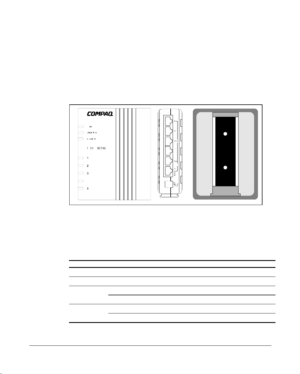
Hardware Description
This section describes the hub’s main components. The following illustration
shows the hub’s front panel, back panel, and hub stand.
Figure 1
LED Indicators
The 1005 hub provides LED indicators that let you instantly monitor the status
of each port plus the overall status of the hub.
Power Green Power indicator.
Utilization 40% Yellow Traffic is 40% or more of Ethernet bandwidth (10Mbps).
. Front and Side Panels, and Hub Stand
LED Color Indication
Yellow Collision indicator; flashes to show network collision.Collision
Unlit No collisions.
Green RJ-45 port linked; flashes to indicate traffic is being received.Link-RX/Partition
Yellow RJ-45 port partitioned.
Page 6

. . . . . . . . . . . . . . . . . . . . . . . . . . . . . .
RJ-45 Ports
There are five RJ-45 MDI-X station ports and one RJ-45 MDI uplink port, each
providing a 10 Mb/s Ethernet channel. To connect to a workstation or server,
attach straight-through unshielded or shielded twisted-pair cabling to any station
port.
To connect to another Netelligent 1005 or compatible hub, attach straightthrough twisted-pair cabling to the UPLINK port. You can also connect to
another hub by running straight-through twisted-pair cabling from a station port
on this hub to a crossover port on the other hub. However, if you must connect
to another hub via stations ports at both ends of the cable, use crossover cabling.
: Using the UPLINK port disables Port 5.
NOTE
Power Connector
The power adapter plugs into this connector. The power adapter plugs into the
main AC power source at 100V, 120V, 220-230V, or 240V at 50 to 60Hz.
3
Installing the Hub
This section describes different ways of using the supplied hub stand and
explains how to attach the hub to devices in your network.
Using the Hub Stand
You can attach and use the hub stand in the following ways:
Q
To stand the hub upright on a desk or shelf, slide the stand onto the base
of the hub.
Q
To lay the hub flat, slide the stand onto the back of the hub.
Q
To mount the hub directly on a wall or office partition, first attach the
stand to the mounting location with two small screws. Then slide the
back of the hub onto the stand.
Compaq Netelligent 1005 10Base-T Hub User Guide
Page 7

. . . . . . . . . . . . . . . . . . . . . . . . . . . . . .
Netelligent 1005 10Base-T Hub User Guide
4
Making Hub Connections
Follow these steps to connect the hub to devices in your network.
1. Select an appropriate location.
2. Connect a workstation to any available RJ-45 station port (1-5) on the
hub using unshielded twisted-pair (UTP) cable. All connected devices
must be within 100 meters of the hub. You can connect up to five
workstations if you use the hub in a stand-alone configuration.
Uplinking Hubs
To uplink hubs, connect one hub’s UPLINK port to a normal
workstation port of another 1005 or compatible hub.
To limit the number of hubs in a path (when cascading more than two
hubs), link several hubs to one central hub. Be sure there is only one
path between any two stations on the network.
3. Plug the power adapter into the hub, and connect it to a grounded
electrical outlet.
Page 8

. . . . . . . . . . . . . . . . . . . . . . . . . . . . . .
Troubleshooting
Symptom: The partition indicator lights steadily or flashes.
Causes: The hub has a partitioned port, or a workstation’s network adapter or
network software is defective. Flashing green and yellow indicates activity
while the port is partitioned.
Solution: If a port has been partitioned, the hub automatically enables the port
when the fault is corrected, or the hub detects activity without incurring a
collision.
Symptom: The port link indicator remains off.
Causes: A workstation’s network adapter, cable, or hub port is defective.
Solution: The most common cause is a defective network adapter or cable
connection. Check the corresponding cable connections, or the workstation’s
network adapter for possible defects. Verify that the correct cable type (straight
or crossover) is being used. (Note that crossover cable is only required if you
cascade hubs via the RJ-45 station ports; that is, the UPLINK port is not used.)
Replace the defective cable or adapter.
5
Other Important Tips
Q
Ensure that cable distances, repeater limits, and other physical aspects of
the installation do not exceed IEEE 802.3 recommendations.
Q
Verify that the cabling type used is correct. Then tighten all cable
connections.
Q
Be sure the network adapter cards installed in the workstations and
cable connections are in good working condition.
Q
Be sure the network is properly configured and that all hubs are
connected to the network. Sometimes, hubs may be unintentionally
disconnected from the network.
Q
You cannot use Port 5 and the UPLINK port at the same time. Be sure
that when you use the UPLINK port, Port 5 is not connected to a node.
Compaq Netelligent 1005 10Base-T Hub User Guide
Page 9

. . . . . . . . . . . . . . . . . . . . . . . . . . . . . .
+
Netelligent 1005 10Base-T Hub User Guide
6
Hub's RJ-45 Pin Assignments
The following table and illustrations show the pin wiring for both straight and
crossover twisted-pair cable. (Note that crossover cable is required only if you
cascade hubs using RJ-45 Ports 1-5; that is, the UPLINK port is not used.)
MDI-X Assignment
Pin
1 Input Receive Data + Output transmit Data +
2 Input Receive Data - Output transmit Data -
3 Output transmit Data + Input Receive Data +
6 Output transmit Data - Input Receive Data -
4,5,7,8 Not Used Not Used
. RJ-45 Pin Configuration
Figure 2
Straight-Through Crossover
(Hub) (Adapter) (Hub) (Hub)
1 IRD+ 1 OTD+ 1 IRD+ 1 IRD+
2 IRD- 2 OTD- 2 IRD- 2 IRD3 OTD
6 OTD- 6 IRD- 6 OTD- 6 OTD-
(Port 1~5)
3 IRD+ 3 OTD+ 3 OTD+
MDI-Assignment
(UPLINK Port)
Page 10

. . . . . . . . . . . . . . . . . . . . . . . . . . . . . .
Specifications
7
Transmission Technique
Topology
Access Method
:
:
Standard Conformance
Media Supported
Interfaces
:
:
:
Baseband
Tree or Star
CSMA/CD, 10 Mb/s
:
IEEE 802.3 10Base-T
Category 3, 4, 5 twisted-pair cable
Five RJ-45 station ports, One RJ-45
uplink port
Hub-to-Workstation Distance
Dimensions
:
:
100m max cable length
4.72 x 3.78 x 1.10 Inches
(12.1 x 9.7 x 2.82 cm)
Power Requirements: 8VAC, 50/60 Hz, 5 watts
Power Adapter: External power
adapter - 8 VAC, 8VA for
100V/120V/220-230V/240V AC input
Temperature: 0°C to 50°C (Standard Operating)
Humidity: 5% to 95% (Noncondensing)
Certification: CE Mark
Emissions: FCC Class B, VCCI Class 2,
CISPR Class B
Immunity: IEC 801-2,3,4, EN60555-2 Class D,
EN60555-3
Safety: UL, CSA, TÜV/GS
Compaq Netelligent 1005 10Base-T Hub User Guide
Page 11

. . . . . . . . . . . . . . . . . . . . . . . . . . . . . .
Netelligent 1005 10Base-T Hub User Guide
8
EMI Warning
FCC Class B Certification
This device complies with Part 15 of the FCC Rules. Operation is subject to the
following conditions:
Q
This device may not cause harmful interference, and
Q
This device must accept any interference received, including interference
that may cause undesired operation.
WARNING:
limits for a Class B digital device, pursuant to Part 15 of the FCC Rules.
These limits are designed to provide reasonable protection against harmful
interference in a residential installation. This equipment generates, uses and
can radiate radio frequency energy and, if not installed and used in
accordance with the instructions, may cause harmful interference to radio
communications. However, there is no guarantee that interference will not
occur in a particular installation. If this equipment does cause harmful
interference to radio or television reception, which can be determined by
turning the equipment off and on, the user is encouraged to try to correct
the interference by one or more of the following measures:
• Reorient or relocate the receiving antenna
• Increase the separation between the equipment and receiver
• Connect the equipment into an outlet on a circuit different
from the one which the receiver is connected to
• Consult the dealer or an experienced radio/TV technician for help
You are cautioned that changes or modifications not expressly approved by the
party responsible for compliance could void your authority to operate the
equipment.
You may use unshielded twisted-pair (UTP) for RJ-45 connections.
This equipment has been tested and found to comply with the
Page 12

. . . . . . . . . . . . . . . . . . . . . . . . . . . . . .
9
WARNING:
to prevent electrostatic discharge whenever handling this equipment.
The Interference Handbook
You may find the Interference Handbook a helpful resource. This booklet,
prepared by the Federal Communication Commision, is available from the U.S.
Government Printing Office. Washington, D.C. 20402. Stock No. 004-00000345-4. You can also view this document on the World Wide Web at the
following address:
www.fcc.gov/Bureaus/Compliance/WWW/tvibook.html
:
In order to maintain compliance with the limits of a Class B digital device,
NOTE
Compaq requires that you use a quality interface cable when connecting to this
device. Changes or modifications not expressly approved by Compaq could void the
users authority to operate this equipment. Suggested cable type is: Category 3, 4,
or 5 twisted-pair (10Base-T).
VCCI Class 2 Compliance
Wear an antistatic wrist strap or take other suitable measures
This product also complies with CISPR22 Class B (EN55022 Class B).
EN55022 Declaration of Conformance
This is to certify that the Compaq 1005 10Base-T Hub is shielded against the
generation of radio interference in accordance with the application of Council
Directive 89/336/EEC, Article 4a. Conformity is declared by the application of
EN55022:1987 Class B (CISPR 22:1985/BS 6527:1988).
Compaq Netelligent 1005 10Base-T Hub User Guide
Page 13

. . . . . . . . . . . . . . . . . . . . . . . . . . . . . .
Netelligent 1005 10Base-T Hub User Guide
10
CE Mark Declaration of Conformance
This is to certify that this product complies with ISO/IEC Guide 22 and
EN45014. It conforms to the following specifications:
EMC: EN55022(1988)/CISPR-22(1985) class B
EN60555-2(1995) class D
EN60555-3 prEN55024-2(1990)/IE801-2(1991) 4kV CD, 8kV AD pr
EN55024-3(1991)/IE801-3(1984) 3V V/m pr
EN55024-4(1992)/IE801-4(1988) 1kV - (power line) 0.5kV - (signal line)
This product complies with the requirements of the Low Voltage Directive
73/23/EEC and the EMC Directive 89/336/EEC.
WARNING:
Les raccordeurs ne sont pas utilisé pour le système téléphonique!
The connectors are not for telephone system use.
Page 14

. . . . . . . . . . . . . . . . . . . . . . . . . . . . .
I-1
Index
C
CE Mark Declaration of Conformance
7, 10
Class B 9
Crossover cable 6
CSA 7
E
Electrical outlet 4
Electrostatic discharge 9
EMI warning 8
Ethernet bandwidth 2
F
FCC Class B Certification 8
H
Hub-to-workstation distance 7
I
Power
adapter 7
requirements 7
socket 3
R
Radio interference 9
Residential installation 8
RJ-45
connections 8
MDI uplink port 3
MDI-X station ports 3
Pin assignments 6
Pin configuration 6
port 2, 3, 6
port 5 5
station port 4, 5, 7
S
Straight-through crossover 6
T
Telephone system use 10
Television reception 8
Topology 7
IEEE 802.3 10Base-T 7
IEEE 802.3 recommendations 5
Important tips 5
Interference Handbook 9
M
Mb/s Ethernet channel 3
MDI-X assignment 6
Media supported 7
P
Physical installation 5
Pin wiring 6
U
UPLINK port 3, 4, 5, 6
Uplinking hubs 4
W
Warranty registration card 1
Workstation network adapter 5
Compaq Netelligent 1005 10Base-T Hub User Guide
 Loading...