

Page 1

Storage Area Network
Configurations for
RA8000/ESA12000 on
Windows NT – Intel
Application Note
AA-RHH6B-TE
Visit Our Web Site for the Latest Information
At Compaq we are continually making additions to our storage solutions product line. Please check
our web site for more information on the complete line of Fibre Channel storage products, product
certification, technical information, updates to this document, and other available documentation.
This information can be accessed through our web page at:
www.compaq.com/storageworks
Introduction
This application note describes fibre channel switch based Storage Area Network (SAN)
configurations for RA8000/ESA12000 storage systems on Windows NT Intel platforms. For mixed
platform heterogeneous SAN configurations refer to the "Heterogeneous Storage Area Networks"
applicati o n n o t e, an d the ap p l i cab l e pl at fo rm s p eci fi c ap p l i cat ion notes listed i n Table 3.
Enterprise Network Storage Architecture (ENSA)
The Compaq Enterprise Network Storage Architecture is key to supporting Compaq’s NonStop
eBusiness strategy; through ENSA, Compaq leverages industry standards to allow deployment of
storage where applications need it. ENSA uses the Compaq StorageWorks product family to deliver
the storage solutions that address non-stop computing requirements like availability, reliability,
performance, scalability, manageability, and data backup/restore capabilities. ENSA addresses the
storage is s u es that o u r cust o m ers ex p ect to face n o w an d in the fu t u re. C o mpaq S ANs add res s today’s
issues including:
• Data protect ion
• High availability
• Increased distance
• High connectivity
• High bandwidth
• Multi-vendor platform support
• Enterprise backup support
• Economical capacity growth
• Scalability
• Investment protection
With the addition of multi-switch fibre channel Fabric support in the RA8000/ESA12000 FC storage
products and the integration of Enterprise Backup Solutions into the SAN, Compaq has taken the next
evolutionary step in delivery of the ENSA vision. Our customers can now realize the full benefits of a
scalable Storage Area Network providing the robust backbone needed to address dispersed server
operation with shared storage access and backup acros s t h e ent erpris e.
Copyright © 1999, Com paq C om puter Corporation AA–RHH6B–TE
Printed in U. S.A. Page 1
All Rights Re se rved
Page 2

SAN Configurations for RA8000/ESA12000 on Windows NT - Intel
Product Overview
The RA8000 and ESA12000 FC storage systems are based on a common architecture and offer
customers centralized management, high availability, and exceptional performance and scalability in
open systems environments. These products provide a Fibre Channel storage solution with industry
leading SAN support utilizing both FC-Fabric (switch) and FC-AL (arbitrated loop) technology.
The RA8000 FC is a mid-range storage system available in a pedestal enclosure for departmental use
in the office. It can also be instal l ed in server rack s fo r small data cent ers . An eas y- t o-d ep l o y, flexible
solution for open systems, the RA8000 supports up to 2.6 TB of storage.
The ESA12000 FC, designed for the data center, is available in three easy-to-order building blocks;
each optimized for specific, high-capacity customer requirements. The ESA12000 FC offers
unprecedented levels of storage, s cali n g in performance and capacit y as user requi rem ent s in creas e.
These storage systems incorporate the latest in RAID technology providing RAID levels 0, 1, 0+1,
adaptive 3/5, and non-RAID disks. Compaq’s implementation of RAID capability assures that data
availability will be maintained despite hardware failure. Features such as read ahead cache and
mirrored writ e b ack cache improve or mini mi ze t h e affect o n p erfo rm an ce while preservin g d at a
availability and supporting high availability.
The RA8000/ESA12000 FC platform kits contain the necessary operating sys tem speci fi c s oft ware
and documentation needed to install, configure, and monitor your storage system. All platform kits
include the StorageWorks Command Console (SWCC) for storage management operations including
configuring, status inquiry and notification facilities. SWCC provides a user oriented graphical user
interface (GUI) s i m p l i fy i ng t he most co m plex o f sto rag e m an agem en t o perat i o n s .
Microsoft Cluster Server (MSCS)
A Windows NT MSCS cluster enables two servers to share an RA8000 or ESA12000 FC storage
system through a Fibre Channel bus. If a server failure should occur, the storage I/O is re-routed
through to the functioning server. This process, called cluster failover, requires no resource
downtime ensuring the high availability of data.
The RA8000 and ESA12000 FC storage systems are supported in Windows NT MSCS cluster
configurations. All of the cluster configurations provide full cluster failover capabilities through a
fibre channel bus connected to both cluster servers.
In addition to cluster failover, the RAID array controllers can be configured in transparent failover
mode to protect against the unlikely event of a single controller failure. This feature eliminates
controllers as single points of failure and is invoked without the need for server intervention.
For the highest availability, two hardware paths between the cluster servers and the RA8000 or
ESA12000 FC storage system can be configured using Compaq’s Secure Path for Windows NT. This
configuration provides two separate physical paths between the servers and the storage.
Secure Path for Windows NT
StorageWorks Secure Path is a high availability software product providing continuous data access
for RA8000 and ESA12000 FC storage products configured on Windows NT platforms. Redundant
hardware, advanced RAID technology and automated failover capability are used to enhance fault
tolerance and availability. Secure Path effectively eliminates controllers, interconnect hardware and
host bus adap t ers as sin g l e poi n t s of fai lure in the storage s y stem .
Key to Secure Path’s functionality is the capability of RA8000/ESA12000 FC dual HSG80
controll ers t o operat e i n t h e activ e/ act i v e M u lti p l e-B u s fail o v er m o de. T his failover mode allo ws each
controller to be configured on its own bus and to process I/O independently under normal operation.
Available s t o rag e u ni ts are “preferred” to one or the other of the two controllers which determines
which controller path is used for access at system boot time. During runtime, storage units may be
moved between paths at anytime through use of the management utility without disrupting operations.
Page 2 AA–RHH6B–TE
Page 3

Application Note
Controllers in Multip le - Bus failover mode monitor each other and au t o m atical ly failover sto rag e u nits
from the failed member of a controller pair. The Secure Path software detects the failure of I/O
operations to complete on a failed path and automatically re-routes all traffic to the surviving path.
Controller and path failover is completed seamlessly, without process disruption or data loss.
The Secure Path management utility provides continuous monitoring capability and identifies failed
paths and failed-over storage units. To facilitate static load balancing, storage units can be moved
between paths using simple “drag-and-drop” operations.
The integration of Secure Path, Windows NT Clustering, and StorageWorks RAID Array Fibre
Channel technology provides the maximum level of fault-tolerance, data availability, and
performance req uired for miss i o n-critical environ m ents.
Enterprise Backup Solutions
The Enterprise Backup Solution for Legato NetWorker is an integration of industry-standard
application software and hardware that provides a complete enterprise class tape solution. The
implementation combines tape and disk storage on a single SAN providing backup capabilities for up
to 7 Windows NT Intel or Tru64 UNIX servers and 2 disk storage systems using a single shared tape
library. The Legato NetWorker and SmartMedia software applications manage the backup operations
for the solution
. Future releases will support increased capabilities.
SAN Concepts
A Storage Area Network interconnects multiple shared storage environments and servers into a
storage network. All storage can be managed from a single location or from multiple locations. All of
the storage becomes available to any server, regardless of physical location.
SAN Management
SAN management tools and product features provided with the RA8000/ESA12000 storage systems
include the following:
• SAN Storage and Switch Management
SWCC – Utilized to manage and monitor s torag e s y s t em s, sto rag es et s , an d SAN fibre
channel switches including configuration, status inquiry and notification facilities.
• SAN Enterprise Backup Management
Legato NetWorker and SmartMedia software manages and automates the backup-and-restore
process using Compaq servers, disk arrays, tape libraries and FC interconnect hardware.
• SAN Access Management
Switch Fabric Zoning – The FC switch Zoning feature provides a means to control SAN
access at the node port level. Zoning can be used to separate one physical Fabric into many
virtual Fabrics consisting of selected server and storage ports. This capability allows you to
setup barriers between different operating environments, to deploy logical Fabric subsets by
creating defined server and/or storage groups, or to create temporary server and storage zones
for tape backup. Zones may be configured dynamically and the number of zones and zone
membership are effectively unlimited. Nodes can be in multiple zones to allow for
overlapping depending on the desired access control. Use of Zoning is supported in both
homogeneous Windows NT SAN configurations and heterogeneous mixed platform SAN
configurations.
Selective Storage Presentation (SSP) – The RAID Array SSP feat u re p ro vi d es a mean s to
control access at the storages et l evel . SSP is an exclusi v e RA8000/ESA12000 storage system
feature that allows multiple servers or host bus adapters (HBA) to share access to the sam e
RAID array reliabl y , with each server or HBA's sto rag esets (LUNs) present ed ex cl u s i v el y to
AA–RHH6B–TE Page 3
Page 4

SAN Configurations for RA8000/ESA12000 on Windows NT - Intel
those th at are all o wed acces s . Ad d i tio n al l y, SSP al lows the s etting of host modes and LUN
offsets for each HBA connected t o the array. The host mode is special l y t ai l ored to the
storage com m u nication techni qu es o f the o perat ing system. The LUN offs et feat u re al l o ws
higher numbered LUNs in a RAID Array to be presented in a range required by specific
operating s ys tems. The SSP feature also provi d es a mean s to t rack the n u m ero us F C HB As
within servers at tached to a SAN by ident i fyin g each b y Worl dw i d e ID (WWID).
Additional information about these products and features is available in the documentation listed in
Table 4
SAN Performance Consideration s
The performance of an application on a system that utilizes RA8000 or ESA12000 FC storage can be
limited by many different components of the system and the configuration of the SAN. Some of the
possible component limiting factors include the host CPU(s), memory size, FC HBA, RAID
controllers, or the specific configuration of disks used behind the controllers. At the SAN level,
performance can be limited by the number and arrangement of FC switches and inter-switch links
(ISL) in the F ab ri c, an d t h e way servers an d s torag e s y s t em s are con n ect ed t o t h e Fabr i c. Th e l im i ti ng
factor can move to any of these areas depending on the workload. Identifying the limits will assist in
determining the best configuration for a given application.
Table 1 lists the upper limit performance specifications for the components of the RA8000 and
ESA12000 FC storage systems based on testing using standard storage performance tests and
methodologies. These numbers should be used to compare component level performance as a means
to determine the best configuration from a performance perspective. User application tests may not
necessarily reach t h es e l ev el s of perfo rm an ce as ap p l i cat i o n s may p erform additional l ev el s of
processing fo r each I/ O. The controller s p eci fi cat i o n s li sted s h ow bot h cache (n o d i s k access ) an d
media (with dis k access ) limitations.
The limits are based on I/O performance (I/O’s per second) - typical of small transfer applications
such as databases and mail, and bandwidth performance (MB’s per second) - typical of large transfer
applications such as video and graphics.
Table 1 Performance Limits of FC-Fabric Components
Transfer Size IO/sec (small transfer sizes,
random access)
Operation Type Read Write Read Write
FC HBA - KGPSA-BC 15,500 14,250 86 51
FC Switch (see note)
FC Switch ISL ( s ee not e)
Single HSG80 Controller
(1 Active Port)
Single HSG80 Controller
(2 Active Ports)
Dual HSG80 Controll ers
(2 Active/2 Standby Ports)
Dual HSG80 Controll ers
(4 Active Ports)
400,000
25,000
12,000 Cache
4,100 Media
12,000 Cache
4,100 Media
24,000 Cache
8,200 Media
24,000 Cache
8,200 Media
400,000
25,000
9,000 Cache
4,000 Media
9,000 Cache
4,000 Media
18,000 Cache
8,000 Media
18,000 Cache
8,000 Media
MB/sec (large transfer sizes,
sequential access)
1600
100
77 Cache
54 Media
98 Cache
54 Media
154 Cache
102 Media
195 Cache
102 Media
1600
100
50 Cache
44 Media
100 Cache
47 Media
101 Cache
88 Media
178 Cache
88 Media
EBS TBS TBS TBS TBS
Page 4 AA–RHH6B–TE
Page 5

Application Note
NOTE
Fibre channel switch and ISL performance limits are
theoretical. Actual measured performance is lower due to
limits unrelated to the switch.
SAN Configuration Guidelines
The following sections provide information about configuring SANs including the base Fabric design
selection, fibre channel Fabric rules, platform and disk storage connectivity rules, Enterprise Backup
integration rules and Compaq Secure Path for Windows NT rules. The configuration information is
presented in the form of rules to provide for flexibility and customization depending on the specific
customer need. In addition to the listed rules, also shown are examples of recommended SAN
configurations based on the number and arrangement of fibre channel switches in a Fabric. The
example “SAN Fabric Configurations” illustrates proper application of the listed rules with regard to
fibre channel switch arrangement, switch interconnection in a Fabric, and platform/storage
connections. The exact SAN Fabric configuration used for your specific application should begin
with one of the base SAN configurations shown. In choosing a Fabric configuration you should
consider capacity, connectivity, availability, distance, backup, and performance needs as well as
future growth requirements.
It is not required that you configure server and storage in the SAN exactly as depicted in the
illustrations, however it is strongly recommended that the switch interconnection rules and platform
connectivity rules be strictly adhered to.
This application note describes homogeneous Windows NT SAN configurations. It is expected that
customers may desire to implement a heterogeneous SAN consisting of many different operating
system platforms. Whether implementing a homogeneous or heterogeneous SAN, it is necessary to
adhere to the p l at fo rm specific rules and maxi m ums fo r each g iven pl atform within the SAN.
SAN Design Selection Process
It is suggested that the following general steps be followed when initially designing a SAN.
1. Considering capacity, connectivity, availability, distance, performance, and backup requirements,
select the SAN Fabric configuration that best fits your needs. Refer to the configuration
illustrations, notes, Fabric rules, and platform server and storage connectivity rules. Using the
maximum server and maximum storage counts shown as the upper bound limits determine the
specific number of servers or storage required number for your particular installation.
• If you want a lower server count than the maximum listed: You may increase the storage
count, but only to the upper limit indicated for maximum storage, and provided you do not
exceed the platform limits listed in Table 2 for HBAs/Server and Controller Ports/HBA
• If you want a lower storage count than the maximum listed: You may increase the server
count, but only to the upper limit indicated for maximum servers, and provided you do not
exceed the platform limits listed in Table 2 for Servers/Storage System
• If capacity or co n n ect i o n n eeds are g reater than prov i d ed in a 4 switch Fabric, consider
implementing multiple 4-switch Fabrics (future releases will support inter-connection of
multiple Fabrics into a single Fabric to provide for growth and scaling of the SAN).
2. If you are configuring a homogeneous Windows NT Intel SAN, refer to the Windows NT Intel
Server/Storage configuration rules in this document to determine how best to configure servers
and storage. Line 1 in Table 2 lists the configuration maximums for Windows NT Intel platforms
in a homogeneous SAN configuration.
3. If you are configuring a heterogeneous SAN, refer to the appropriate platform application note(s)
and the heterogeneous SAN application note referenced in Table 3 to ensure platform interaction
AA–RHH6B–TE Page 5
Page 6

SAN Configurations for RA8000/ESA12000 on Windows NT - Intel
Line 2 in Table 2 lists the configuration maximums for Windows NT Intel platforms in a
heterogeneous SAN configuration.
4. If implementing a SAN for high availability storage using Compaq Secure Path for Windows NT,
refer to the Secu re Path config ur at ion ru l es.
5. If implementing a SAN integrating Compaq Enterprise Backup on your SAN, refer to the EBS
connectivity and configuration rules
6. Select the desired method(s) of SAN management and access control bas ed on your specific
needs. Use SWCC for storageset management, and controller based SSP or switch based Zoning
(or both) for d isk stor age acces s co n t ro l . Use Secure Path Manager t o m anag e h i gh avai l ab i li t y,
use Legato NetWorker and SmartMedia software to manage the backup-and-restore process.
SAN Configuration Rules and Maximums
The following sections list the SAN design rules as they apply to Fabric configurations, Windows NT
Intel platforms for servers and storage, enterprise backup integration, and high availability storage.
Fabric Rules
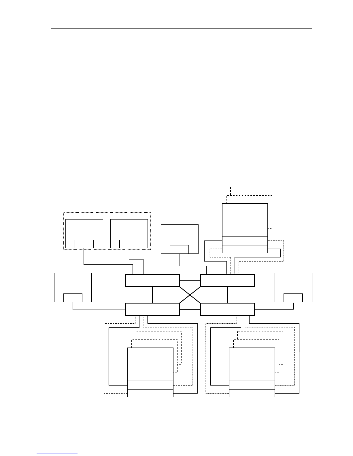
• Up to 4 fibre chann el s witch es t otal i n a single Fabric - a SAN with all swit ches in t erco n nected.
All Compaq FC 16-port and 8-port switch models are supported inter-mixed
• A server can attach to multiple multi-switch Fabrics (Figure 1). The number of separate Fabrics
per server or total number of switches per server in separate Fabrics is based on the specific
server model capabilities and the maximum number of FC HBAs supported
• Within a single Fabric, maximum of 1 switch hop between servers and storage, maximum of 2
switch hops worst case with a single fault - a Fabric can re-route to a 2-hop path on a single link
failure. A hop is defined as 1 or more connections between two FC switches, for example; 2
switches cas cad ed = 1 ho p. S erv er t o FC swit ch s eg m en t s and St o rag e t o FC s wit ch s e gments are
not counted as hops
• Within a sin g l e Fab ri c wh ere s wi tches are interconnected, each FC swi t ch mus t hav e a u niqu e
domain number (Domain_ID)
• Up to 15 inter-switch links (ISLs) between any 2 switches
• Minimum cable segment length is 2 meters
• Up to 200 meters per cable segment using short-wavelength laser GBICs and 62.5 micron multi-
mode fiber optic cable. With multiple cable segments 600 meters total distance nominal, 800
meters worst cas e wi t h a sing l e fault re-route, betw een s erv er an d s t or age
• Up to 500 meters per cable segment using short-wavelength laser GBICs and 50u multi-mode
fibre optic cable. With multiple cable segments 1.5 km total distance nominal, 2.0 km worst case
with a single fault re-route, between server and storage
• Up to 10 km per ISL cable segment using long-wavelength laser GBICs and 9u single-mode fibre
optic cable. With multiple cable segments 11 kilometers total distance nominal, 21 km worst case
with a single fault re-route, between server and storage. 10 km links are only supported in switch
to switch connections
Figure 1 One Server to Multiple 4-Switch Fabrics
Fabric 1 Fabric 3
Page 6 AA–RHH6B–TE
Server
Fabric 2
SHR-1585
Page 7

Application Note
Windows NT Server/Storage Rules
Table 2 describes the Windows NT Intel platform maximums when in a homogenous Windows NT
SAN and when using Windows NT Intel platforms in a heterogeneous mixed platform SAN.
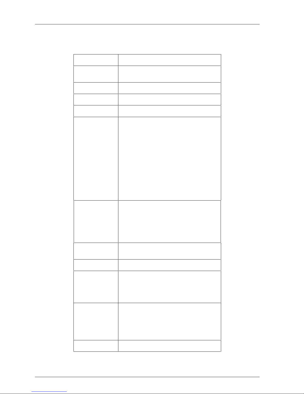
Table 2 Guidelines fo r Windows NT Int el Platf orm Supported Maximums
Active
Maximum
Supported
Number of:
Windows NT SAN 4 4 8 4 16
Heterogeneous SAN
Host Bus
Adapters
per Server
(1)
Controller
Host Ports
(HBA Targets)
per HBA
(2)
LUNs
per HBA
(3)
Target
HBAs per
Server per
Switch Zone
(4)
Active
Servers
per
Storage
System
8
(5)
Table Notes:
1. The actual maxi m um number of host bu s adapters per serv er i s dependent on the specific server mod el.
The recommend ed m aximum number of active HSG80 contro ller host ports a single HBA can simultaneousl y
2.
access, the ac tual number of Targ et s available is 16, inc luding the HBA.
3.
The maximum number of LUNs per SCSI target. T he maximum numbe r of LUN s pe r t arg et a ho st bu s adapter can
address in a SAN may be l ess.
4.
The maximum number of HBAs per ser ver that can be connected to the same sw it ch zone.
5. This column gives th e maximum number o f active hosts for one s torage system in a Homog eneous SAN using the
specific operat ing s ystem. This assumes 1 FC H B A per ho st for non-HA Transpar ent Failover configurations and
2 FC HBAs per host for HA Multi pl e-b us Failover configurat ions. The Heterogen eous Access entry is the
maximum total number of active hos t conn ections when mul tiple ope rating systems are ac cessing the same sto rag e
system.
• All configurations are supported under Windows NT 4.0 with SP4 (minimum)
• For Windows NT, all server connections into the SAN use a FC-Fabric based HBA. FC-AL and
FC FL-Port HBA connections into the SAN are not supported for Windows NT platforms
• The maximum number of FC HBAs per server is 4, or total allowed in the server if less than 4.
Use Selecti v e St o rag e P res en t ation (see bel ow) to as sig n speci fi c L UNs exclusively to each HB A
• The maximum number of active controller ports per FC HBA is 4
• Any combination of Windows NT Servers - standalone or clustered, and RA8000/ESA12000
storage systems is allowed per SAN configuration, provided these rules are followed:
1. A maximum of 16 Windows NT servers (assumes 1 FC HBA per server for non-HA and
2 FC HBAs per server for HA) per RA8000 or ESA12000 dual controller storage system,
with a maxim um of 8 servers co n fi g u red o n each active port. See “Extended
Configurations” description below when g reat er than 4 servers have access t o t h e same
HSG80 controller host port pair
2. All specific SAN configuration rule limits are followed. Refer to the individual SAN
Fabric configurations
• Extended Configurations - If you configure greater than 4 (up to 8) Windows NT servers
(assumes one FC HBA per server) for access to a single host port on an RA8000/ESA12000 Fibre
Channel s torage system , y o u mu st s el ect the “Extended Configuration” check box in the
StorageWorks Windows NT Platform Kit Fibre Channel Software Setup utility custom
installation setup. Each NT server in this configuration must have the option selected. Selecting
this option will adjust registry settings for your KGPSA host bus adapter to operate in an
"Extended Configuration" environment
• All configurations require the Connection Name Operating System parameter set to “WINNT”
• When configuring HSG80 controllers for access from Windows NT servers only, the controll er
SCSI mode should be set to “SCSI-2” and the Command Console LUN (CCL) must be disabled.
When configuring controllers for access from Windows NT and other platforms that requi re
“SCSI-3” mode, set the controllers to SCSI-3 mode. When set in SCSI-3 mode the CCL will be
fixed at LUN 0. This will reduce the total number of LUNs available from 8 to 7 for all server
connections.
AA–RHH6B–TE Page 7
Page 8

SAN Configurations for RA8000/ESA12000 on Windows NT - Intel
• Each active con t ro l l er h os t po rt p res en t s one SCS I Targ et ID wi th u p to eigh t LUNs to each
server (FC HBA) that has a connected path through the Fabric to the port.
• The maximum number of LUNs per HSG80 controller pair is 128
• Dual redundant controllers can be configured for Transparent Failover Mode or Multiple-Bus
Failover Mode. Multiple-bus Failover mode requires Compaq Secure Path for Windows NT on
the server
• Each storage s y s t em can be configured u s i n g SWCC or t h e Comm an d L ine In t erface (C L I)
through either the HSG80 controller maintenance serial port or a TCP/IP interface
• All configurations utilize ACS V8.5F (Array Controller Software) configured for FABRIC
topology
• ACS V8.5 provides for up to 64 connection name entries. For dual controllers in Transparent
Failover M o d e, up to 2 co nn ect i o n ent ri es are creat ed fo r each s erv er HB A, thus a total of 32
server HBAs are visible to a storage system at any given time. In Multiple-Bus Failover Mode, up
to 4 connectio n en t ri es are creat ed fo r each serv er HB A, so a total of 16 server HBAs are vi s i b l e.
Note: The maximum number of server HBAs supported on a storage system is 16. Each storage
system in the SAN will automatically add connection name entries upon initial power up. As a
result, in certain SAN configurat i ons it is possible to exceed the number of available connect i on
name entries i n a st o rage s y stem prior to the additi o n of ent ri es fo r the s p eci fi c s erv er HB As th at
you want access to. This could result in the inability of a storage system to properly connect to a
desired server HB A i n the SAN. To avoid this, you can configure s p eci fi c s erv er HB As an d
specific st o rag e s y s t ems into FC Switch Zon es o f up to 32 S erv ers wh en in T ran s p aren t F ail o v er
and up to 16 Servers when in Multiple-bus Failover.
• Rename connection names. By default new connection names are automatically added to the
controller connection name table by the controllers when they detect a path to an adapter from
each active controller host port. The default connect i on name assigned by the controllers will be
“!NEWCONnn”, where nn is a num b er fro m 1 to 64. After t h e co ntrol l ers d et ect al l pat h s,
rename each connection name to be more meaningful to the configurati on i. e., SERVER1P1,
SERVER 1P 2, etc. (connectio n names can be a maximum of 9 characters ) .
• Selective Storage Presentation - for configurations with more than 1 FC HBA in a server or more
than one server accessing through the same HSG80 controller host port,
Use the Connection Name Unit Offset value to set the range of unit numbers to be visible
from each server or HB A (u sing the CLI, “SET connection-name UNIT_OFFSET = n”)
Use the Unit Connection Name parameter to allow exclusiv e acces s t o un i ts fro m each s erver
or HBA (using the CLI, “SET unit-number DISABLE_ACCESS_PATH = ALL
ENABLE_ACCESS_PATH = connection-name”)
Shared access between different servers to the same
storage unit (LUN) requires specific application software
(i.e., MSCS) to ensure proper data preservation.
• LUNs (logical units) can consist of single disks (JBOD), a storageset of multiple disks or a
partition (up to 8), configured for a specific RAID level of 0, 1, 0 + 1, or 3/5
• The maxim u m storag e cap aci t y s t at ed (2 .6 TB) assumes 36 GB dis k s, increas es in disk driv e
capacity will increase overall storage capacity for the same enclosure footprint
Enterprise Backup Solution Integration Rules
• Supports Legato NetWorker backup for up to 7 Windows NT or Tru64 UNIX Servers
• Supports all Compaq FC 16-port and 8-port switch models inter-mixed
• Connected to the SAN using FC switch Fabric topology connection
• Up to 10 km between FC switch and a tape controller using long-wavelength laser GBICs and 9u
single-mode fiber optic cable
Page 8 AA–RHH6B–TE
NOTE
Page 9

Application Note
• Up to 2 Fibre Channel Tape Controllers
• Maximum of 1 TL895 library
• Up to 7 tape drives
• Maximum of 1 switch hop between servers and a tape controller
• Supports backup for up to 2 RA8000 or 1 ESA12000 (4 controller pairs) storage systems
Compaq Secure Path for Windows NT Ru les
• All High Availability Multiple-Bus Failover configurations require Compaq Secure Path for
Windows NT (minimum revision v2.2) and two physical paths to a pair of controller ports on the
storage system
• One instance of the Secure Path Manager can control two paths on up to 4 storage systems. Two
Paths equates to 2 FC HBA’s connected to 2 controller host ports (i.e., Port 1 of Controller A and
Port 1 of Controller B). Another instance is required to control two paths to the other pair of ports
on a storage system (Port 2 of Controller A and Port 2 of Controller B)
• For standalone servers (non-cluster), a separate instance of the Secure Path Manager is run on
each server. For Windows NT Clusters, one instance of t h e Secure Path Manager can be run for
both cluster servers. For centralized management, multiple instances of the Secure Path Manager
can be run on a sin gle Client provided n et w or k acces s is available bet w een the Client and al l HA
servers.
• For servers acces s i ng co n t ro l l er ho st p o rt 1 use LUN n umber an d offs et valu es i n th e rang e o f 0 –
99, for controller host port 2 use number and offset values in the range 100 -199
• Use the Unit Preferred Path parameter to assign units to a specific controller. Distribute units
equally across both controllers for proper load balancing
• SSP - Storages et s (LUNs ) mus t be enab l ed for acces s fro m b oth p at hs us ing the Un i t Connection
Name parameter feature
• Secure Path configurations require a minimum of two FC HBAs in a server. Each FC HBA must
be connected to a different FC switch, and for cable symmetry, should be on the same switch port
number, for example:
Server 1 FC HBA 1 to FC Switch 1 - Switch Port 1
Server 1 FC HBA 2 to FC Switch 2 - Switch Port 1
Server 2 FC HBA 1 to FC Switch 1 - Switch Port 2
Server 2 FC HBA 2 to FC Switch 2 - Switch Port 2
It is highl y recom m en d ed t h at th e cab l i n g sch em e s h o wn in each S ecu re Path multipl e-b us
configurations be followed as depicted.
• For version 2.2, the Secure Path Manager uses the controller serial number to determine which
path (controller) will be displayed first in the GUI, thus the lower value serial number will be
displayed first in the display as the top path labeled “CONTROLLER A”. The higher controller
serial number will be displayed as the bottom path and labeled as “CONTROLLER B”.
AA–RHH6B–TE Page 9
Page 10

SAN Configurations for RA8000/ESA12000 on Windows NT - Intel
Configuration Descriptions
Table 3 lists six SAN Fabric configuration examples for RA8000 and ESA12000 storage systems
when using Windows NT Intel platforms. The configurations are based on the rules listed in the
configuration guideline section. They show the limits with regard to:
• Total number and arrangement of fibre channel switches in a single Fabric, or multiple Fabrics
for high availability
• Maximum number of servers and storage systems per Fabric configuration
• Recommended Fabric switch configurations optimized for general purpose, maximum capacity,
maximum connectivity, highest availability, backup, or highest performance
The configurations are listed in order based on the number of switches in the Fabric. This follows a
logical progression where you may desire to initially configure a small SAN containing a single FC
switch, then add a second switch for high availability or increased connectivity, and additional
switches as cap aci t y an d co nn ect ivity needs increas e.
The maximum server counts and maximum storage counts listed for each configuration show the
upper bound limits - either maximum servers or maximum storage, for that switch arrangement.
Depending on your connectivity or storage capacity needs you may choose to implement your SAN
maximized for one or the other, or a lesser number of either. All configurations allow the flexibility to
trade-off server and storage system count based on total FC switch port availability, however you
cannot exceed the upper bound limits listed or the platform limits in Table 2 for each configuration.
All configurations support a mix of both clustered and non-clustered (MSCS) servers. All
configurations are supported with all Compaq supplied 16-port and 8-port FC switches.
Table 3 RA8000 / ESA12000 SAN Fabric Configurations Windows NT - Index
SAN Fabric
Configuration #
1 One FC Switch, Controller Transparent Failover Mode,
Integrated EBS
2 Two FC Switches, High Availability, Secure Path, Controller
Multiple-Bus Failover Mode, Integrated EBS
3 Two FC Switches, Cascaded, Controller Transparent Failover
Mode, Integrated EBS
4 Four FC Switches, Cascaded High Availability Fault Tolerant
Fabric, Secure Path, Controller Multiple-Bus Failover Mode,
Integrated EBS
5 Three FC Switches, Cascaded Meshed Fabric, Controller
Transparent Failover Mode
6 Four FC Switches, Cascaded Meshed Fabric, Controller
Transparent Failover Mode
Description Pages
Additional Inform at ion/Ref erences
11 – 12
13 – 14
15 – 16
17 – 19
20 – 22
23 – 25
A table of all available product documentation is included at the end of this application note for
reference. Refer to the documents listed for more details on the product installation and
configuration.
Page 10 AA–RHH6B–TE
Page 11

Application Note
SAN Fabric Configuration 1 - One FC Switch, Controller Transparent Failover
Mode, Integrated EBS
SAN Fabric Configuration 1 (Figure 2) is a general-purpose configuration that provides connectivity
for multiple servers, disk storage, and tape storage all on a single SAN. Up to 12 separate noncooperating servers or up to 6 pairs of clustered cooperating servers can be connected through a 16port swi t ch prov i d i n g access fro m al l s ervers to a single storag e s y stem . With an 8-port FC switch up
to 4 servers can be co n n ect ed t o 1 st o rag e s y stem . Wi th either switch t y p e the n umber o f s to rag e
systems can b e increas ed if the number of s erv ers i s reduced t o p ro vid e add i ti o nal switch port s for
storage. The HSG80 array controllers within the RA8000 or ESA12000 storage enclosure are
configured in Transparent failover mode providing full controller redundancy in the unlikely event of
either controller failing.
Figure 2 One Switch Fabric Configuration Example
NT Cluster
Windows NT
Intel
Server
FC HBA
Windows NT
Intel
Server
FC HBA
Active
Standby
. . . . .
FC Switch
24 Disks
24 Disks
RA8000 or
ESA12000 FC
Dual Controller
24 Disks
Port 1 A Port 2
Port 1 B Port 2
Windows NT
Intel
Server
FC HBA
Standby
Active
SAN Configuration 1 Server/Storage Connectivity Rules
Windows NT
Intel
Server
FC HBA
SHR-1427
• Any mix of Windows NT Intel Servers - standalone or clustered, and storage systems using these
maximums. Assumes 1 FC HBA per server, an even storage port count, and no EBS ports.
• 16-port FC Switch, total number of switch ports available for Servers and Storage is 16
Maximum Server Connectivity,
Up to 12 Servers and 1 Storage System (4 storage ports/2 Active, 2 Standby)
[16 – 4 storage ports = 12 server ports]
Maximum of 8 servers configured on any one active controller host port
Or Maximum St o rag e C ap aci ty,
Up to 4 Storage Systems (14 storage ports/7 Active, 7 Standby) and 2 Servers
[16 – 2 server ports = 14 storage ports]
• 8-port FC Switch, total number of switch ports available for Servers and Storage is 8
Maximum Server Connectivity,
Up to 4 Servers and 1 Storage System (4 storage ports/2 Active, 2 Standby)
[8 – 4 storage ports = 4 server ports]
AA–RHH6B–TE Page 11
Page 12

SAN Configurations for RA8000/ESA12000 on Windows NT - Intel
Or Maximum St o rag e C ap aci ty,
Up to 2 Storage Systems (6 storage ports/3 Active, 3 Standby) and 2 Servers
[8 – 2 server ports = 6 storage ports]
• All HSG80 array controllers configured in Transparent Failover Mode
• EBS Integration Supported
SAN Configuration 1 Fabric Rules
• Total Switches = 1, 16-port or 8-port
• Maximum Switch Hops (nominal) = 0
• Maximum Sw itch Hop s (wors t cas e )= 0
• Maximum Dis t an ces
Up to 500 meters per FC cable segment, 1 km total server to storage using 50 micron multimode fibre optic cable. Refer to general Fabric rules for other cable types
SAN Configuration 1 Notes
• When configured with greater than 4 Windows NT Servers per active controller host port,
classifi ed as an “NT Extended Configuration” (refer to the StorageWorks Windows NT Platform
Kit FC Software Setup Utility)
• For servers acces s i ng co n t ro l l er ho st p o rt 1 use LUN n umber an d offs et valu es i n th e rang e o f 0 –
99, for controller host port 2 use number and offset values in the range 100 -199
• Performance con s i d erat i o n s, assuming rel atively equal serv er l o ad :
If using a single storage system, for balanced performance across all servers configure half of
the servers on each o f t h e cont roller port pairs. If us i n g multiple storage systems configure an
equal numb er o f s erv ers o n each st o rag e s y s t em.
The recommended maximum number of controller host ports configured per FC HBA is 2 for
high bandwidth applications and 4 for high throughput applications.
Page 12 AA–RHH6B–TE
Page 13

Application Note
SAN Fabric Configuration 2 – Two FC Switches, High Availability, Secure Path,
Controller Multiple-Bus Failover Mode,
Integrated EBS
SAN Fabric configuration 2 (Figure 3) is a high availability storage configuration that uses two
separate Fabrics to provide two data paths between servers and disk storage configured in MultipleBus failover mode. Tape storage can be configured on one of the Fabrics to provide backup and
restore capabilities. Up to 15 separate (non-cooperating) servers or up to 7 pairs of clustered
(cooperating) servers can be connected through two 16-port FC switches with 1 storage system. With
8-port F C sw itch es u p to 6 servers can b e co nn ected to 1 storage sy s t em. With ei th er s wi t ch typ e t h e
number of storage systems can be increased if the number of servers is reduced to provide switch
ports for storage. This SAN configuration utilizes the high availability features of controller MultipleBus failover and Compaq Secure P at h for Windows NT software. Wi t h 2 FC HBAs in each server,
and 2 FC switches, a second separate path to the storage is provided to each server. The 2 switches
form isolated Fabrics providing the highest level of storage path fault tolerance should a failure occur
with any path component - FC HBA, FC Switch, Fabric path interconnect, or storage controller. NonHA configured servers and storage configured in Transparent Failover Mode are supported in this
configuration, h o wev er acces s m ay b e li mited to one or the other o f the two Fabrics u nles s 2 FC
HBAs are utilized, each connect ed t o a different Fabric.
Figure 3 Two Switch HA Fabric Configuration Example
Windows NT
Intel
Server
FC HBA 1 FC HBA 2
Windows NT
Server
FC HBA 1 FC HBA 2
FC Switch #1
Intel
Active
Active
. . . .
24 Disks
24 Disks
RA8000 or
ESA12000 FC
Dual Controller
24 Disks
Port 1 A Port 2
Port 1 B Port 2
Windows NT
Intel
Server
FC HBA 1 FC HBA 2 FC HBA 1 FC HBA 2
FC Switch #2
Active
Active
Windows NT
Intel
Server
SAN Configuration 2 Server/Storage Connectivity Rules
• Any mix of Windows NT Intel Servers - standalone or clustered, configured for HA or non-HA,
and any mix of Multiple-bus Failover and Transparent Failover storage systems using these
maximums. Assumes all servers configured for HA, 2 FC switches and 2 FC HBA’s per server,
an even storage port count, and no EBS ports.
AA–RHH6B–TE Page 13
SHR-1428
Page 14

SAN Configurations for RA8000/ESA12000 on Windows NT - Intel
• 16-port FC Switches, total number of switch ports available for Servers and Storage is 32
Maximum Server Connectivity,
Up to 14 Servers and 1 Storage System (4 Active storage ports)
[(32 – 4 storage ports)/2 = 14 servers]
Maximum of 8 FC HBA's configured on any one active controller host port
Or Maximum St o rag e C ap aci ty,
Up to 6 Storage Sy stem s (2 4 Acti ve sto rag e p orts) and 4 HA Servers
[32 – 8 server ports = 24 storage ports]
Maximum of 4 active controller host ports per FC HBA
• 8-port FC Switches, total number of switch ports available for Servers and Storage is 16
Maximum Server Connectivity,
Up to 6 Servers and 1 St or age System (4 Active storag e p or t s )
[(16 – 4 storage ports)/2 = 6 servers]
Or Maximum Storage Capacity,
Up to 3 Storage Sy stem s (1 2 Acti ve sto rag e p orts) and 2 HA Servers
[16 – 4 server ports = 12 storage ports]
• For dual path high availability, HSG80 controller pairs are configured in Multiple-Bus Failover
Mode. For non-HA single path servers, controllers are configured in Transparent Failover Mode
• EBS Integration Supported
SAN Configuration 2 Fabric Rules
• Total Switches = 2, 16-port or 8-port
• Maximum Switch Hops (nominal ) = 0
• Maximum Sw itch Hop s (wors t cas e ) = 0
• Maximum Dis t an ces :
Up to 500 meters per FC cable segment, 1 km total server to storage using 50 micron multimode fibre optic cable. Refer to general Fabric rules for other cable types
SAN Configuration 2 Notes
• Uses Compaq Secure Path for Windows NT (minimum version 2.2)
• When configu red wi t h g reat er than 4 FC HBA's per acti v e con t ro ll er ho s t po rt, cl as s ified as an
“NT Extended Configuration” (refer to the StorageWorks Windows NT Platform Kit FC
Software Setup Utility)
• One instan ce of the Secure Path Manager i s req u i red fo r each s t an d al o ne s erv er o r each pai r of
clustered s ervers . One inst ance can co n t ro l 2 pat hs o n up to 4 storag e s y s t em s. All ins t an ces can
be run from a single Client if desired
• Each server is co n fi g u red fo r acces s t o t w o path s and t wo con t ro l l er p orts , us ing either Port 1 of
both controllers or Port 2 of both controllers
• For servers acces s i ng co n t ro l l er ho st p o rt 1 use LUN n umber an d offs et valu es i n th e rang e o f 0 –
99, for controller host port 2 use number and offset values in the range 100 -199
• Performance con s i d erat i o n s, assuming rel atively equal serv er l o ad :
If using a single storage system, for balanced performance across all servers configure half of
the servers on each o f t h e cont roller port pairs. If us i n g multiple storage systems configure an
equal numb er o f s erv ers o n each st o rag e s y s t em.
The recommended maximum number of controller host ports configured per FC HBA is 2 for
high bandwidth applications and 4 for high throughput applications.
Page 14 AA–RHH6B–TE
Page 15

Application Note
SAN Fabric Configuration 3 – Two FC Switches, Cascaded, Controller
Transparent Failover Mode, Integrated EBS
SAN Fabric configuration 3 (Figure 4) is a general purpose single Fabric cascaded switch
configuration that provides increased server, disk, and tape storage connectivity capabilities. Up to 22
separate (non-cooperating) servers or up to 11 pairs of clustered (cooperating) servers can be
connected through a 16-port switch providing access from all servers to 2 storage system s. Wi t h an 8port FC s wit ch up t o 10 servers can b e co n nected to 1 storag e s y stem. With either s wit ch t y p e the
number of storage systems can be increased if the number of servers is reduced to provide switch
ports for storage. A minimum of 1 ISL is required between the 2 switches, more may be required
based on the specific server and storage configuration and count, and the applications utilized. The
ISL(s) can be up to 10 km allowing connectivity between two remote sites. The HSG80 array
controllers within the RA8000 or ESA12000 storage enclosure are configured in Transparent failover
mode providing full controller redundancy in the unlikely event of either controller failing.
Figure 4 Two Switches, Cascad ed F abri c Con fi gu rat io n Example
24 Disks
24 Disks
Windows NT
Intel
Server
FC HBA
NT Cluster
Windows NT
Windows NT
Intel
Server
FC HBA
Intel
Server
FC HBA
Active
FC Switch #1
RA8000 or
ESA 12000 FC
Dual Controller
24 Disks
Port 1 A Port 2
Port 1 B Port 2
Standby
ActiveStandby
Windows NT
Intel
Server
FC HBA
FC Switch #2
24 Disks
24 Disks
RA8000 or
ESA 12000 FC
Dual Controller
24 Disks
Active
Port 1 A Port 2
Port 1 B Port 2
Standby
ActiveStandby
SHR-1551
SAN Configuration 3 Server/Storage Connectivity Rules
• Any mix of Windows NT Intel Servers - standalone or clustered, and storage systems using these
maximums. Assumes 1 FC HBA per server, an even storage port count, and no EBS ports.
• 16-port FC Switches, total number of switch ports available for Servers and Storage is 30
Maximum Server Connectivity,
Up to 22 Servers and 2 Storage Systems (8 storage ports/4 Active, 4 Standby)
AA–RHH6B–TE Page 15
Page 16

SAN Configurations for RA8000/ESA12000 on Windows NT - Intel
[32 – 2 ISL ports – 8 storage ports = 22 server ports]
Maximum of 16 servers configured on one controller pair
Maximum of 8 servers configured on any one active controller host port
Or Maximum St o rag e C ap aci ty,
Up to 7 Storage Systems (26 Storage Ports/13 Active, 13 Standby) and 4 Servers
[32 – 2 ISL ports – 4 server ports = 26 storage ports]
Maximum of 4 active controller host ports per FC HBA
• 8-port FC Switches total number of switch ports available for Servers and Storage is 14
Maximum Server Connectivity,
Up to 10 Servers and 1 Storage System (4 storage ports/2 Active, 2 Standby)
[16 – 2 ISL ports – 4 storage ports = 10 server ports]
Maximum of 8 servers configured on any one active controller host port
Or Maximum St o rag e C ap aci ty,
Up to 3 Storage Systems (12 storage ports/6 Active, 6 Standby) and 2 Servers
[16 – 2 ISL ports – 2 server ports = 12 storage ports]
Maximum of 4 active controller host ports per FC HBA
• All HSG80 array controllers configured in Transparent Failover Mode
• EBS Integration Supported
SAN Configuration 3 Fabric Rules
• Total Switches = 2, 16-port or 8-port
• Maximum Switch Hops (nominal ) = 1
• Maximum Sw itch Hop s (wors t cas e ) = 1
• Maximum number of ISLs between the two switches = 15
• Maximum Dis t an ces :
Up to 500 meters per FC cable segment, 1.5 km total server to storage when using 50 micron
multi-mode fibre optic cable. Refer to general Fabric rules for other cable types
Up to 10 km per inter-switch link, 11 km total server to storage when using 9 micron single
mode fibre optic cable and long wave GBICs
SAN Configuration 3 Notes
• Each FC Switch must have a unique domain number (Domain_ID)
• When configured with greater than 4 Windows NT Servers per active controller host port,
classifi ed as an “NT Extended Configuration” (refer to the StorageWorks Windows NT Platform
Kit FC Software Setup Utility)
• For servers acces s i ng co n t ro l l er ho st p o rt 1 use LUN n umber an d offs et valu es i n th e rang e o f 0 –
99, for controller host port 2 use number and offset values in the range 100 -199
• Performance con s i d erat i o n s, assuming rel atively equal serv er l o ad :
If using two storage systems, for balanced performance across all servers, configure half of
the servers on each o f t h e sto rag e s ys tems and equally on th e cont ro l l er p or t pai rs .
The recommended maximum number of controller host ports configured per FC HBA is 2 for
high bandwidth applications and 4 for high throughput applications.
Use these general performance rules to determine the optimum number of ISLs required
between both switches.
For balanced S AN perform an ce co n fi g u re 1 s torage syst em on each FC switch.
For the high es t avai l ab l e p erfo rm an ce, whenever poss i b l e, d ev i ces t h at exch ang e t h e h i g h es t
amount of data should be connected to the same FC switch, for example, servers and the
storage assigned to them should be configured on the same FC switch, otherwise:
For high bandwidth applications – One ISL between switches for every 2 st orag e co n t ro ller
ports on one s wit ch b ei n g access ed by a s erv er o n the other switch.
For high throughput applications – One ISL between s wit ch es for ev ery 6 stor age co n t ro l l er
ports on one s wit ch b ei n g access ed by a s erv er o n the other switch.
Page 16 AA–RHH6B–TE
Page 17

Application Note
SAN Fabric Configuration 4 – Four FC Switches, Cascaded High Availability
Fault Tolerant Fabric, Secure Path, Controller
Multiple-Bus Failover Mode, Integrated EBS
SAN Fabric configuration 4 (Figure 5) is a high availability storage cascaded switch configuration
that provides increased server, disk, and tape storage connectivity capabilities. This configuration
uses two separate Fabrics to provide two data paths between servers and disk storage configured in
Multiple-Bus failover mode. Tape storage can be configured on one of the Fabrics to provide backup
and restore capabilities. Up to 26 separate (non-cooperating) servers or up to 13 pairs of clustered
(cooperating) servers can be connected through 4 16-port FC switches to 4 storage systems. With 8port FC s wit ches up to 6 servers can be co n n ect ed t o 1 sto rag e s y s t em. Wi t h eith er s w i t ch ty p e the
number of storage systems can be increased if the number of servers is reduced to provide switch
ports for storage. This SAN configuration utilizes the high availability features of controller MultipleBus failover and Compaq Secure Path for Windows NT software. With 2 FC HBA’s in each server
and 4 FC switches in 2 separate isolated Fabrics, a second separate path to the storage is provided to
each server. Th e 2 s w i t ch pai rs fo rm is o l at ed F abr i cs pr ov idi n g the h i ghest level of storage pat h fault
tolerance should a failure occur with any path component - FC HBA, FC Switch, Fabric path
interconnect, or storage controller. Non-HA configured servers and storage configured in Transparent
Failov er M od e are s u p port ed i n th is co n fi g u rat i o n, ho w ever access may be limit ed to on e or th e oth er
of the two Fabrics unless 2 FC HBAs are utilized, each connect ed t o a different F abri c.
Figure 5 Four Switches, Cascad ed HA F aul t Tol erant Fabric Configuration Example
NT Cluster
Windows NT
Intel
Server
FC HBA1 FC HBA2
Windows NT
Server
FC HBA1 FC HBA2
FC Switch #1
FC Switch #3
24 Disks
24 Disks
Intel
Active
Active
FC Switch #2
FC Switch #4
24 Disks
24 Disks
RA8000 or
ESA 12000 FC
Dual Controller
24 Disks
Port 1 A Port 2
Port 1 B Port 2
24 Disks
24 Disks
Active
Active
Windows NT
Intel
Server
FC HBA
RA8000 or
ESA 12000 FC
Dual Controller
24 Disks
Active Active
Active Active
AA–RHH6B–TE Page 17
Port 1 A Port 2
Port 1 B Port 2
FC HBA1 FC HBA2
Windows NT
Intel
Server
Active
RA8000 or
ESA 12000 FC
Dual Controller
24 Disks
Port 1 A Port 2
Port 1 B Port 2
Standby
ActiveStandby
SHR-1554
Page 18

SAN Configurations for RA8000/ESA12000 on Windows NT - Intel
SAN Configuration 4 Server/Storage Connectivity Rules
• Any mix of Windows NT Intel Servers - standalone or clustered, configured for HA or non-HA,
and any mix of Multiple-bus Failover and Transparent Failover storage systems using these
maximums. Assumes all servers configured for HA, 2 FC switches and 2 FC HBA’s per server
for HA, an even storage port count, and no EBS ports.
• 16-port FC Switches, total number of switch ports available for Servers and Storage is 60
Maximum Server Connectivity,
Up to 26 Servers and 2 Storage Systems (8 Active storage ports)
[(64 – 4 ISL ports – 8 storage ports)/2 = 26 servers]
Maximum of 16 servers configured on any one controller pair
Maximum of 8 servers configured on any one active controller host port
Or Maximum St o rag e C ap aci ty,
Up to 12 Storage S y stem s (4 8 Stor age Ports) and 6 HA Servers
[64 – 4 ISL ports – 12 server ports = 48 storage ports]
Maximum of 4 active controller host ports per FC HBA
• 8-port FC Switches, total number of switch ports available for Servers and Storage is 28
Maximum Server Connectivity,
Up to 12 Servers and 1 Storage System (4 storage ports)
[(32 – 4 ISL ports – 4 storage ports)/2 = 12 server ports]
Maximum of 8 servers configured on any active controller host port
Or Maximum St o rag e C ap aci ty,
Up to 6 Storage Sy stem s (2 2 sto rag e p orts) and 3 HA Servers
[32 – 4 ISL ports – 6 server ports = 22 storage ports]
Maximum of 4 active controller host ports per FC HBA
• For dual path high availability, HSG80 controller pairs are configured in Multiple-Bus Failover
Mode, for single path servers (non-HA) controllers are configured in Transparent Failover Mode
• EBS Integration Supported
SAN Configuration 4 Fabric Rules
• Total Switches = 4, 16-port or 8-port
• Maximum Sw itch Ho ps (no m i n al ) = 1 in each path
• Maximum Sw itch Ho ps (wors t cas e ) = 1 in each pat h
• Maximum nu m b er of ISL s bet ween t h e t wo switch in each path = 15
• Maximum Dis t an ces :
Up to 500 meters per FC cable segment, 1.5 km total server to storage when using 50 micron
multi-mode fibre optic cable. Refer to general Fabric rules for other cable types
Up to 10 km per inter-switch link, 11 km total server to storage when using 9 micron single
mode fibre optic cable and long wave GBICs
SAN Configuration 4 Notes
• Each FC Switch within a path must have a unique domain number (Domain_ID)
• Uses Compaq Secure Path for Windows NT (minimum version 2.2)
• One instan ce of the Secure Path Manager i s req u i red fo r each s t an d al o ne s erv er o r each pai r of
clustered s ervers . One inst ance can co n t ro l 2 pat hs o n up to 4 storag e s y s t em s. All ins t an ces can
be run from a single Client if desired
• Each server is co n fi g u red fo r acces s t o t w o path s and t wo con t ro l l er p orts , us ing either Port 1 of
both controllers or Port 2 of both controllers
• For servers acces s i ng co n t ro l l er ho st p o rt 1 use LUN n umber an d offs et valu es i n th e rang e o f 0 –
99, for controller host port 2 use number and offset values in the range 100 -199
• Depending on the specific number of servers and storage systems utilized in this SAN
configuration, it is possible to exceed the available total number of connection name entries in a
storage system. (See Windows NT Server/Storage Rules). This situation can be avoided by using
Page 18 AA–RHH6B–TE
Page 19

Application Note
• FC switch Zoning to create separate Zones for each of the server groups that you wish to
configure wi t h s p eci fi c sto rag e s y s t em s.
• When configured with greater than 4 Windows NT Servers per active controller host port,
classifi ed as an “NT Extended Configuration” (refer to the StorageWorks Windows NT Platform
Kit FC Software Setup Utility)
• Performance con s i d erat i o n s, assuming rel atively equal serv er l o ad :
If using two storage systems, for balanced performance across all servers, configure half of
the servers on each o f t h e sto rag e s ys tems and equally on th e cont ro l l er p or t pai rs .
The recommended maximum number of controller host ports configured per FC HBA is 2 for
high bandwidth applications and 4 for high throughput applications.
Use these general performance rules to determine the optimum number of ISLs required
between both switches.
For balanced S AN perform an ce co n fi g u re 1 s torage syst em on each FC switch.
For the high es t avai l ab l e p erfo rm an ce, whenever poss i b l e, d ev i ces t h at exch ang e t h e h i g h es t
amount of data should be connected to the same FC switch, for example, servers and the
storage assigned to them should be configured on the same FC switch, otherwise:
For high bandwidth applications – One ISL between switches for every 2 st orag e co n t ro ller
ports on one s wit ch b ei n g access ed by a s erv er o n the other switch.
For high throughput applications – One ISL between s wit ch es for ev ery 6 stor age co n t ro l l er
ports on one s wit ch b ei n g access ed by a s erv er o n the other switch.
AA–RHH6B–TE Page 19
Page 20

SAN Configurations for RA8000/ESA12000 on Windows NT - Intel
SAN Fabric Configuration 5 – Three FC Switches, Cascaded Meshed Fabric,
Controller Transparent Failover
Mode
SAN Fabric configuration 5 (Figure 6) is a meshed Fabric cascaded switch configuration that
provides increased server, disk, and tape storage connectivity capabilities in addition to Fabric
resiliency. All of the switches in the Fabric are interconnected providing alternate paths within the
Fabric. This Fabric feature automatically reconfigures a route to a good path should a component in a
Fabric path fail. Up to 30 separate (non-cooperating) servers or up to 15 pairs of clustered
(cooperating) servers can be connected through 3 16-port FC switches to 3 storage systems. With 8port FC switches up to 14 servers can be connected to 1 storage system. With either switch type the
number of storage systems can be increased if the number of servers is reduced to provide switch
ports for storag e. A minimum of 1 ISL is requi red b et ween each o f the 3 switches, more may be
required based on the specific server and storage configuration and count, and the applications
utilized. The ISL(s) can be up to 10 km allowing connectivity between three remote sites. The HSG80
array controllers within the RA8000 or ESA12000 storage enclosure are configured in Transparent
failover mode providing full controller redundancy in the unlikely event of either controller failing.
Figure 6 Three Switches, Cascaded Meshed Fabric Configuratio n Exampl e
24 Disks
24 Disks
RA8000 or
ESA 12000 FC
Dual Controller
24 Disks
Port 1 A Port 2
Port 1 B Port 2
Standby
ActiveStandby
Windows NT
Intel
Server
FC HBA
Windows NT
Intel
Server
FC HBA
NT Cluster
Windows NT
Intel
Server
FC HBA
Active
Windows NT
Intel
Server
FC HBA
Active
FC Switch #2
24 Disks
24 Disks
RA8000 or
ESA 12000 FC
Dual Controller
24 Disks
Port 1 A Port 2
Port 1 B Port 2
FC Switch #1
Standby
ActiveStandby
FC Switch #3
ESA 12000 FC
Dual Controller
Active
Port 1 A Port 2
Port 1 B Port 2
24 Disks
24 Disks
RA8000 or
24 Disks
Windows NT
Intel
Server
FC HBA
Standby
ActiveStandby
SHR-1578
SAN Configuration 5 Server/Storage Connectivity Rules
• Any mix of Windows NT Intel Servers - standalone or clustered, and storage systems using these
maximums. Assumes 1 FC HBA per server, an even storage port count, and no EBS ports.
Page 20 AA–RHH6B–TE
Page 21

Application Note
• 16-port FC Switches, total number of switch ports available for Servers and Storage is 42
Maximum Server Connectivity,
Up to 30 Servers and 3 Storage Systems (12 storage ports/6 Active, 6 Standby)
[48 – 6 ISL ports – 12 storage ports = 30 server ports]
Maximum of 16 servers configured on any one controller pair
Maximum of 8 servers configured on any active controller host port
Or Maximum St o rag e C ap aci ty,
Up to 9 Storage Systems (36 storage ports/18 Active, 18 Standby) and 6 Servers
[48 – 6 ISL ports – 6 server ports = 36 storage ports]
Maximum of 4 active controller host ports per FC HBA
• 8-port FC Switches, total number of switch ports available for Servers and Storage is 18
Maximum Server Connectivity,
Up to 14 Servers and 1 Storage System (4 storage ports/2 Active, 2 Standby)
[24 – 6 ISL ports – 4 storage ports = 14 server ports]
Maximum of 8 servers configured on any active controller host port
Or Maximum St o rag e C ap aci ty,
Up to 4 Storage Systems (16 storage ports/8 Active, 8 Standby) and 2 Servers
[24 – 6 ISL ports – 2 server ports = 16 storage ports]
Maximum of 4 active controller host ports per FC HBA
• All HSG80 array controllers configured in Transparent Failover Mode
SAN Configuration 5 Fabric Rules
• Total Switches = 3, 16-port or 8-port
• Maximum Switch Hops (nominal ) = 1
• Maximum Sw itch Hop s (wors t cas e ) = 2
• Maximum number of ISLs between any two switches = 15
• Maximum Dis t an ces :
Up to 500 meters per FC cable segment, 1.5 km total server to storage (2.0 km worst case)
when using 50 micron multi-mode fibre optic cable. Refer to general Fabric rules for other
cable types
Up to 10 km per inter-switch link, 11 km total server to storage (21 km worst case) when
using 9 micron single mode fibre optic cable and long wave GBICs
SAN Configuration 5 Notes
• Each FC Switch must have a unique domain number (Domain_ID)
• When configured with greater than 4 Windows NT Servers per active controller host port,
classifi ed as an “NT Extended Configuration” (refer to the StorageWorks Windows NT Platform
Kit FC Software Setup Utility)
• For servers acces s i ng co n t ro l l er ho st p o rt 1 use LUN n umber an d offs et valu es i n th e rang e o f 0 –
99, for controller host port 2 use number and offset values in the range 100 -199
• Performance con s i d erat i o n s, assuming rel atively equal serv er l o ad :
If using three st o rag e s y s t em s, fo r balanced p erformance across al l servers, con fi g u re o ne
third of the s erv ers o n each o f the s torage systems and eq u al l y on the co n t ro l ler port pairs.
The recommended maximum number of controller host ports configured per FC HBA is 2 for
high bandwidth applications and 4 for high throughput applications.
Use these general performance rules to determine the optimum number of ISLs required
between both switches.
For balanced S AN perform an ce co n fi g u re 1 s torage syst em on each FC switch
For the high es t avai l ab l e p erfo rm an ce, whenever poss i b l e, d ev i ces t h at exch ang e t h e h i g h es t
amount of data should be connected to the same FC switch, for example, servers and the
storage assigned to them should be configured on the same FC switch, otherwise:
AA–RHH6B–TE Page 21
Page 22

SAN Configurations for RA8000/ESA12000 on Windows NT - Intel
For high bandwidth applications – One ISL between s wi tches for every 2 storag e co n t ro ller
ports on one s wit ch b ei n g access ed by a s erv er o n the other switch.
For high throughput applications – One ISL between s wit ch es for ev ery 6 stor age co n t ro l l er
ports on one s wit ch b ei n g access ed by a s erv er o n the other switch.
Page 22 AA–RHH6B–TE
Page 23
Application Note
SAN Fabric Configuration 6 – Four FC Switches, Cascaded Meshed Fabric,
Controller Transparent Failover
Mode
SAN Fabric configuration 6 (Figure 7) is a meshed Fabric cascaded switch configuration that
provides the maximum server and storage connectivity available in a single Fabric. All of the
switches in the Fabric are interconnected providing alternate paths within the Fabric. This Fabric
feature automatically reconfigures a route to a good path should a component in a Fabric path fail. Up
to 40 separate (non-cooperating) servers or up to 20 pairs of clustered (cooperating) servers can be
connected through 4 16-port FC switches to 3 storage systems. With 8-port FC switches up to 16
servers can be con n ect ed t o 1 sto rag e s y s t em. With ei ther s w i t ch typ e t h e num ber o f st or age s y s tems
can be increased if the number of servers is reduced to provide switch ports for storage. A minimum
of 1 ISL is required between each of the 4 swi t ch es an d a minim um o f 2 ISLs are req u i red t o cross
couple the 4 switches as shown. Additional ISLs may be required based on the specific server and
storage configuration and count, and the applications utilized The cross-coupled ISLs ensure that the
hop count within the Fabric does not exceed 2 for a single path failure. The ISL(s) can be up to 10 km
allowing connectivity between four remote sites. The HSG80 array controllers within the RA8000 or
ESA12000 storage enclosure are configured in Transparent failover mode providing full controller
redundancy in the unlikely event of either controller failing.
Figure 7 Four Switches, Cascad ed Meshed Fabric Configuration Examp le
24 Disks
24 Disks
RA8000 or
ESA 12000 FC
Dual Controller
24 Disks
Port 1 A Port 2
Port 1 B Port 2
Standby
ActiveStandby
Windows NT
Intel
Server
FC HBA
NT Cluster
Windows NT
Intel
Server
FC HBA
Windows NT
Intel
Server
FC HBA
Active
Windows NT
Intel
Server
FC HBA
Active
AA–RHH6B–TE Page 23
FC Switch #1
FC Switch #3
24 Disks
24 Disks
RA8000 or
ESA 12000 FC
Dual Controller
24 Disks
Port 1 A Port 2
Port 1 B Port 2
Standby
ActiveStandby
FC Switch #2
FC Switch #4
ESA 12000 FC
Dual Controller
Active
Port 1 A Port 2
Port 1 B Port 2
24 Disks
24 Disks
RA8000 or
24 Disks
Windows NT
Intel
Server
FC HBA
Standby
ActiveStandby
SHR-1552
Page 24

SAN Configurations for RA8000/ESA12000 on Windows NT - Intel
SAN Configuration 6 Server/Storage Connectivity Rules
• Any mix of Windows NT Intel Servers - standalone or clustered, and storage systems using these
maximums. Assumes 1 FC HBA per server, an even storage port count, and no EBS ports.
• 16-port FC Switches, total number of switch ports available for Servers and Storage is 52
Maximum Server Connectivity,
Up to 40 Servers and 3 Storage Systems (12 storage ports/6 Active, 6 Standby)
[64 – 12 ISL ports – 12 storage ports = 40 server ports]
Maximum of 16 servers configured on any one controller pair
Maximum of 8 servers configured on any active controller host port
Or Maximum St o rag e C ap aci ty,
Up to 12 Storage Systems (46 storage ports/23 Active, 23 Standby) and 6 Servers
[64 – 12 ISL ports – 6 server ports = 46 storage ports]
Maximum of 4 active controller host ports per FC HBA
• 8-port FC Switches, total number of switch ports available for Servers and Storage is 20
Maximum Server Connectivity,
Up to 16 Servers and 1 Storage System (4 storage ports/2 Active, 2 Standby)
[32 – 12 ISL ports – 4 storage ports = 16 server ports]
Maximum of 16 servers configured on any one controller pair
Maximum of 8 servers configured on any active controller host port
Or Maximum St o rag e C ap aci ty,
Up to 4 Storage Systems (16 storage ports/8 Active, 8 Standby) and 4 Servers
[32 – 12 ISL ports – 4 server ports = 16 storage ports]
Maximum of 4 active controller host ports per FC HBA
• All HSG80 array controllers configured in Transparent Failover Mode
NOTE
High availability storage using Secure Path for Windows
NT and Controller Multiple-bus Fa ilover Mode is currently
not supported in this configuration.
SAN Configuration 6 Fabric Rules
• Total Switches = 4, 16-port or 8-port
• Maximum Switch Hops (nominal ) = 1
• Maximum Sw itch Hop s (wors t cas e ) = 2
• Maximum number of ISLs between any two switches = 15
• Maximum Dis t an ces :
Up to 500 meters per FC cable segment, 1.5 km total server to storage (2.0 km worst case)
when using 50 micron multi-mode fibre optic cable. Refer to general Fabric rules for other
cable types
Up to 10 km per inter-switch link, 11 km total server to storage (21 km worst case) when
using 9 micron single mode fibre optic cable and long wave GBICs
SAN Configuration 6 Notes
• Each FC Switch must have a unique domain number (Domain_ID)
• When configured with greater than 4 Windows NT Servers per active controller host port,
classifi ed as an “NT Extended Configuration” (refer to the StorageWorks Windows NT Platform
Kit FC Software Setup Utility
• For servers acces s i ng co n t ro l l er ho st p o rt 1 use LUN n umber an d offs et valu es i n th e rang e o f 0 –
99, for controller host port 2 use number and offset values in the range 100 -199
• Depending on the specific number of servers and storage systems utilized in this SAN
configuration, it is possible to exceed the available total number of connection name entries in a
Page 24 AA–RHH6B–TE
Page 25

Application Note
• storage system. (See Windows NT Server/Storage Rules). This situation can be avoided by using
FC switch Zoning to create separate Zones for each of the server groups that you wish to
configure wi t h s p eci fi c sto rag e s y s t em s.
• Performance con s i d erat i o n s, assuming rel atively equal serv er l o ad :
If using four storage systems, for balanced performance across all servers configure one
quarter of the s erv ers o n each o f the s torage systems an d equal l y on t he cont ro l l er p o rt pai rs .
The recommended maximum number of controller host ports configured per FC HBA is 2 for
high bandwidth applications and 4 for high throughput applications.
Use these general performance rules to determine the optimum number of ISLs required
between both switches.
For balanced S AN perform an ce co n fi g u re 1 s torage syst em on each FC switch
For the high es t avai l ab l e p erfo rm an ce, whenever poss i b l e, d ev i ces t h at exch ang e t h e h i g h es t
amount of data should be connected to the same FC switch, for example, servers and the
storage assigned to them should be configured on the same FC switch, otherwise:
For high bandwidth applications – One ISL between switches for every 2 st orag e co n t ro ller
ports on one s wit ch b ei n g access ed by a s erv er o n the other switch.
For high throughput applications – One ISL between s wit ch es for ev ery 6 stor age co n t ro l l er
ports on one s wit ch b ei n g access ed by a s erv er o n the other switch.
AA–RHH6B–TE Page 25
Page 26
SAN Configurations for RA8000/ESA12000 on Windows NT - Intel
Parts List
• Intel Servers with Microsoft Windows NT 4.0, Service Pack 4 (minimum)
Compaq Part # Description
380551-001 RA8000/ESA12000 FC Solution Software V8.5
for Windows NT/Intel
128697-B21 ACS V8.5F Controller SW
380594-001 Secure Path for WNT
380574-001 KGPSA-BC PCI FC HBA
380560-B21 (Blue)
380560-B22 (Opal)
380670-B21
380580-001 (Blue)
380580-002 (Opal)
380590-B21 (Blue)
380590-B22 (Opal)
380600-001 (Blue)
380600-002 (Opal)
380610-B21 (Blue)
380610-B22 (Opal)
380620-001 (Blue)
380620-002 (Opal)
380630-B21 (Blue)
380630-B22 (Opal)
380570-B21 (Blue)
380570-B22 (Opal)
380568-B21
380640-001 (Blue)
380640-002 (Opal)
380650-B21 (Blue)
380650-B22 (Opal)
158222-B21
158223-B21
380561-B21 FC Optical GBIC
RA8000 Pedestal w/dual HSG80
RA8000 Pedestal w/dual HSG80
RA8000 Rackable w/dual HSG80
ESA12000 w/dual HSG80 24 Slot 60HZ
ESA12000 w/dual HSG80 24 Slot 60HZ
ESA12000 w/dual HSG80 24 Slot 50HZ
ESA12000 w/dual HSG80 24 Slot 50HZ
ESA12000 w/dual HSG80 48 Slot 60HZ
ESA12000 w/dual HSG80 48 Slot 60HZ
ESA12000 w/dual HSG80 48 Slot 50HZ
ESA12000 w/dual HSG80 48 Slot 50HZ
ESA12000 w/2 pairs/dual HSG80 48 Slot 60HZ
ESA12000 w/2 pairs/dual HSG80 48 Slot 60HZ
ESA12000 w/2 pairs/dual HSG80 48 Slot 50HZ
ESA12000 w/2 pairs/dual HSG80 48 Slot 50HZ
Pedestal Expansion 24 slots
Pedestal Expansion 24 slots
Rackable Expansion 24 slots
ESA12000 Expansion 48 Slot 60HZ
ESA12000 Expansion 48 Slot 60HZ
ESA12000 Expansion 48 Slot 50HZ
ESA12000 Expansion 48 Slot 50HZ
SAN Sw i tc h 8 port (n o GBICs)
SAN Switch 16 port (no GBICs)
234457-B21
234457-B22
234457-B23
234457-B24
234457-B25
380691-B21
380595-B21
380694-B21
380588-B21
380589-B21
147599-001
349350-B27 TL895 Tape Library
Page 26 AA–RHH6B–TE
FC 2 Mete r Optic a l Ca b le
FC 5 Mete r Optic a l Ca b le
FC 15 Meter Optical Cable
FC 30 Meter Optical Cable
FC 50 Meter Optical Cable
4GB UW 7200 RPM Disk
9GB UW 7200 RPM Disk
18GB UW 7200 RPM Disk
9GB UW 10000 RPM Disk
18GB UW 10000 RPM Disk
36GB UW 7200 RPM Disk
Page 27

Application Note
Product Details
The RA8000/ESA12000 storage systems utilize the Compaq HSG80 RAID controller running Array
Controller Software (ACS) V8.5. The ACS software is designed to support multiple platforms
providing features including: dual controller operation, two controller failover modes – Transparent
and Multip l e-B u s, mirro red wri t e b ack cach e, read ahead cache, RAID implem en t at ion , di s k
mirroring, and disk partitioning capabilities. In addition, ACS manages host interconnect and protocol
services to provide data for event notification and status such as displayed by SWCC.
The HSG80 controller has two FC host ports providing up to a total of nearly 200 Mbytes per second
of available bandwidth. Disk drives are connected to the controller through 6 UltraSCSI channels
providing up to 40 Mbytes per second per channel of available bandwidth. Servers can use multiple
host bus adapters (HBAs) to multiple RA8000 FC systems for unlimited storage capacity.
The RA8000 FC is supplied in two basic building blocks, a pedestal style cabinet and what has been
termed a “rackable” model. The pedestal is a self-contained desk height cabinet; it is available in
Digital Classic Top Gun blue and in Compaq Opal. The rackable is shipped ready to be mounted in a
19” Compaq rack or a 19 ”cabinet/rack using an included universal RETMA/metric mounting kit.
RA8000 FC controllers come with 64 MB of cache. Cache options allow for 128 MB, 256 MB and
512MB of cache in each controller. ESA12000 FC controllers come with 256 MB of cache. Cache
options allow for 512MB of cache in each controller. Cache feat ures i ncl ude read ahead and mirrored
write back cache for u s e i n o ptimizing performance where redundant capabilities are required for high
availability system configurations. In the rare event that a storage controller fails the mirrored data is
immediately available to the remaining controller for continuing operation.
The RA8000 FC pedestals and rackables come in both single controller and in dual controller models
to allow the customer to select the level of high availability required for their application. A single
controller model can be upgraded to a dual controller model when warranted by the application.
High availability is supported by the use of redundancy and hot swappable components. The RA8000
FC disk enclosures include redundant cooling, and have 5 power supplies providing N+1 redundancy.
Power can be upgraded to full redundancy with the addition of 3 more supplies and a 2nd power
distribution unit for AC input redundancy. StorageWorks components are “hot” swappable including
storage controllers when operating as a redundant pair.
You can configure and monitor the RA8000 and ESA12000 FC using the StorageWorks Command
Console (SWCC). SWCC is included in the HSG80 Software Solutions Platform kit. Using this
client/server tool, you can configure RAID sets locally or over a TCP/IP network. The client provides
an easy to use graphical user interface. It can be us ed to monitor your storage system and notify you
of events by updating a graphical display, sending electronic mail, or alerting via a pager. The
Command Console Client includes applications (or Storage Windows) that communicate with the
Command Console Agent software running on the host platform.
The Command Console client is available on Windows 95, Windows 98, and on Intel platforms
running Windows NT. A Storage Window for the HSG80 controller supports the Array Controller
Software (ACS ) V8.5 an d offers i ntegration with Com paq 's In sigh t Manag er(C IM ). In s i ght M an ager
can receive SNM P t rap s fro m th e Comm and Con s o l e Ag ent and In sig h t Manag er s erv i ces can
directly launch SWCC for notification or configuring operations.
AA–RHH6B–TE Page 27
Page 28

SAN Configurations for RA8000/ESA12000 on Windows NT - Intel
Configuration References
The following documents provide further information on the configuration of RA8000 and
ESA12000 Fibre Channel Storage Systems:
Table4 Configuration Reference Material
Topic Document Title Order Number
Heterogeneous SAN Application
Note
Sun SAN Application Note Storage Area Network Configurations for
HP-UX SAN Application Note
OpenVMS SAN Application Note Storage Area Network Configurations for
Tru64 UNIX SAN Application Note RA8000/ESA12000 FC-Switch Configurations for
Novell Netware Applic ation Note
Windows NT – Intel Standard FCAL Configurations Application
Note
Windows NT – Intel High
Availability FC-AL Configurations
Application Note
Windows NT - Intel
HSG80 Array Controller
Windows NT - Intel
RA8000/ESA12000 Installation
Heterogeneous Storage Area Networks EK-SMA30-AN
RA8000/ESA12000 on Sun Solaris
Storage Area Network Configurations for
RA8000/ESA12000 on HP-UX
RA8000/ESA12000 on OpenVMS
Tru64 UNIX
RA8000/ESA12000 FC-AL Configurations for
Novell Netware
RA8000/ESA12000 FC-AL Configurations for
Windows NT - Intel
RA8000/ESA12000 FC-AL High Availability
Configurations for Windows NT - Intel
Release Notes, HSG80 Array Controller (ACS
V8.5F) for Windows NT Server - Intel
RA8000/ESA12000 Fibre Channel Solution
Software for Windows NT – Intel Installation
Reference Guide
EK-SMA37-AN
EK-SMA32-AN
EK-SMA34-AN
EK-SMA33-AN
EK-FCALN-AA
*AA-RH0RA-TE
*AA–RH0SA–TE
AA–RH0QB–TE
or 387393-002
AA–RFA9C–TE
Windows NT Clusters
Secure Path Installation StorageWorks Secure Path for Windows NT
HSG80 Array Controller
Configuration
HSG80 Array Controller
Command Line Interface
HSG80 Array Controller
Maintenance
StorageWorks Command Console Command Console V2.2 (HSG80) for RAID Array
RAID Array 8000/ESA12000 Fibre Channel
Cluster Solutions for Windows NT
Installation Guide
HSG80 Array Controller ACS Version 8.5
Configuration Guide
HSG80 Array Controller ACS Version 8.5 CLI
Reference Guide
HSG80 Array Controller ACS Version 8.5
Maintenance and Service Guide
8000/ESA12000, User’s Guide
EK-NTC8K-IG
EK-WNTMP-MH
EK-HSG85-CG
or 165144-001
EK-HSG85-RG
or 165145-001
EK-HSG84-SV
or 118620-002
AA–RFA2D–TE
* Refe r t o th e w ebsite fo r th e latest in formatio n .
Legato Net Wo rker and Legato SmartMedia are registered trademarks of Legato Systems, Inc.
Intel is a re gistered t radem ark of Intel Corporation.
Microsoft and Windows are registered trademarks and NT is a trademark of Microsoft Cor poration.
UNIX is a regis tered trademark in the Uni ted States and other countries, licensed exclusively through X/Open Company, Ltd .
Compaq, StorageWorks, HSG, Comp aq Tru64 UNIX, and the Com paq Logo are trademarks of Compaq Computer Co rp oration.
All othe r tr ademarks and registered trademarks are the property of the ir respective owners.
Page 28 AA–RHH6B–TE
 Loading...