

Page 1
Maintenance &
Service Guide
Compaq Deskpro EP Series
of Personal Computers
Page 2

Guide to Features
& Upgrades
Compaq Deskpro EP Series
of Personal Computers
Page 3

Notice
The information in this guide is subject to change without notice.
COMPAQ COMPUTER CORPORATION SHALL NOT BE LIABLE FOR
TECHNICAL OR EDITORIAL ERRORS OR OMISSIONS CONTAINED HEREIN;
NOR FOR INCIDENTAL OR CONSEQUENTIAL DAMAGES RESULTING FROM
THE FURNISHING, PERFORMANCE, OR USE OF THIS MATERIAL.
This guide contains information protected by copyright. No part of this guide may be
photocopied or reproduced in any form without prior written consent from Compaq
Computer Corporation.
2000 Compaq Computer Corporation.
All rights reserved. Printed in the U.S.A.
Compaq, the Compaq logo, and Deskpro Registered U. S. Patent and Trademark Office.
PREMIER
Microsoft, MS-DOS, and Windows are registered trademarks of Microsoft Corporation.
Intel and Pentium are registered trademarks of Intel Corporation.
MMX and Celeron are trademarks of Intel Corporation.
SOUND is a trademark of Compaq Computer Corporation.
•
Product names mentioned herein may be trademarks and/or registered trademarks of
their respective companies.
The software described in this guide is furnished under a license agreement or
nondisclosure agreement. The software may be used or copied only in accordance with
the terms of the agreement.
Maintenance & Service Guide
Compaq Deskpro EP Series of Personal Computers
Fourth Edition (June 2000)
First Edition (July 1999)
Part Number 134011-004
Spare Part Number 143685-001
Compaq Computer Corporation
Page 4

preface
About This Guide
Symbols and Conventions ........................................................................................................ vii
Technician Notes ...................................................................................................................... vii
Locating Additional Documentation ....................................................................................... viii
chapter 1
Product Description
1.1 Model Overview ............................................................................................................. 1-2
1.2 System Design................................................................................................................. 1-3
1.3 Preinstalled Software ......................................................................................................1-4
1.3.1 Ordering Additional Software ............................................................................ 1-4
1.4 Computer Features .......................................................................................................... 1-5
1.4.1 Front Panel Controls and LEDs - 440BX........................................................... 1-5
1.4.2 Front Panel Controls and LEDs - Intel 810/810e ...............................................1-6
1.4.3 Rear Panel Connectors - 440BX......................................................................... 1-7
1.4.4 Rear Panel Connectors - Intel 810/810e............................................................. 1-8
1.4.5 Drive Positions ...................................................................................................1-9
1.5 Serial Number Location ................................................................................................ 1-10
chapter 2
Spare Parts
ONTENTS
C
2.1 System Unit..................................................................................................................... 2-2
2.1.1 System Unit - 440BX .........................................................................................2-2
2.1.2 System Unit - Intel 810/810e.............................................................................. 2-4
2.2 Mass Storage Devices ..................................................................................................... 2-6
2.3 Cables.............................................................................................................................. 2-8
2.4 Standard and Optional Boards ......................................................................................2-10
2.5 Keyboards ..................................................................................................................... 2-15
2.6 Miscellaneous Hardware Kit......................................................................................... 2-16
2.7 Miscellaneous Plastics Kit ............................................................................................2-17
2.8 Miscellaneous Parts....................................................................................................... 2-18
2.9 Shipping Boxes ............................................................................................................. 2-19
2.10 Documentation and Software........................................................................................ 2-19
chapter 3
Removal and Replacement Preliminaries
3.1 Routine Care ...................................................................................................................3-1
3.1.1 Cleaning Safety Precautions............................................................................... 3-1
3.1.2 Cleaning the Computer Case .............................................................................. 3-1
3.1.3 Cleaning the Keyboard ....................................................................................... 3-2
3.1.4 Cleaning the Monitor.......................................................................................... 3-2
3.1.5 Cleaning the Mouse............................................................................................ 3-2
Contents iii
Page 5

3.2 Electrostatic Discharge Information................................................................................ 3-3
3.2.1 Generating Static ................................................................................................3-3
3.2.2 Preventing Electrostatic Damage to Equipment ................................................. 3-3
3.2.3 Personal Grounding Methods and Equipment.................................................... 3-4
3.2.4 Grounding Workstations.....................................................................................3-4
3.2.5 Recommended Materials and Equipment........................................................... 3-4
3.3 Service Considerations.................................................................................................... 3-5
3.3.1 Tools and Software Requirements...................................................................... 3-5
3.3.2 Screws................................................................................................................. 3-5
3.3.3 Cables and Connectors ....................................................................................... 3-5
3.3.4 Hard Drives ........................................................................................................3-6
3.3.5 Plastic Parts......................................................................................................... 3-6
chapter 4
Removal and Replacement Procedures
4.1 Disassembly Sequence Chart .......................................................................................... 4-1
4.2 Disassembly Preparation................................................................................................. 4-2
4.3 Feet Installation............................................................................................................... 4-3
4.4 Logo Plate ....................................................................................................................... 4-4
4.5 Cable Lock ...................................................................................................................... 4-5
4.6 Access Panel ...................................................................................................................4-7
4.7 Front Bezel...................................................................................................................... 4-8
4.8 Power Button................................................................................................................... 4-9
4.9 Subpanel and Bezel Blanks........................................................................................... 4-10
4.10 Power Switch ................................................................................................................4-11
4.11 Mass Storage Devices ................................................................................................... 4-12
4.11.1 Removing an Internal 3.5-Inch Hard Drive...................................................... 4-14
4.11.2 Removing an External 5.25-Inch Drive............................................................ 4-16
4.11.3 Removing an External 3.5-Inch Drive.............................................................. 4-18
4.12 Removing the Drivelocks.............................................................................................. 4-21
4.13 Expansion Boards .........................................................................................................4-24
4.13.1 440BX ..............................................................................................................4-24
4.13.2 Intel 810 and 810e ............................................................................................ 4-25
4.13.3 Removing an Expansion Board ........................................................................ 4-26
4.13.4 Installing an Expansion Board.......................................................................... 4-27
4.14 Board Guide .................................................................................................................. 4-29
4.15 System Memory ............................................................................................................ 4-30
4.15.1 440BX ..............................................................................................................4-30
4.15.2 Intel 810/810e................................................................................................... 4-30
4.16 AGP Graphics Board (440BX) .....................................................................................4-32
4.16.1 AGP Graphics Board Removal (440BX)..........................................................4-32
4.16.2 Graphics Memory Upgrade (440BX)............................................................... 4-33
4.17 Processor Components.................................................................................................. 4-34
4.17.1 Processor........................................................................................................... 4-34
4.17.2 Processor Guide Rails....................................................................................... 4-37
4.18 System Board ................................................................................................................4-39
4.19 Internal Speaker ............................................................................................................4-40
4.20 Lithium Battery .............................................................................................................4-42
4.21 Fan Assembly................................................................................................................4-45
4.22 Power Supply ................................................................................................................4-46
4.23 Converting a Desktop to a Minitower........................................................................... 4-48
4.24 Converting a Minitower to a Desktop........................................................................... 4-51
iv Contents
Page 6

chapter 5
Connectors, Jumpers, and Switches
5.1 System Board .................................................................................................................. 5-1
5.1.1 Connectors, Jumpers, and Switches.................................................................... 5-1
5.1.2 Switches.............................................................................................................. 5-4
5.1.3 Jumpers (440BX)................................................................................................ 5-5
5.1.4 Jumpers (Intel 810/810e).................................................................................... 5-7
5.2 Hard Drives................................................................................................................... 5-10
5.2.1 Using the Cable-Select Feature with Ultra ATA Devices ................................5-10
5.2.2 Drive Jumper Settings ......................................................................................5-11
chapter 6
Specifications
6.1 Specifications.................................................................................................................. 6-1
6.1.1 System ................................................................................................................ 6-1
6.1.2 Interrupts ............................................................................................................ 6-2
6.1.3 DMA................................................................................................................... 6-3
6.1.4 I/O....................................................................................................................... 6-3
6.1.5 Memory Map...................................................................................................... 6-5
6.2 Drives.............................................................................................................................. 6-5
6.2.1 1.44-MB Diskette Drive ..................................................................................... 6-5
6.2.2 Ultra ATA Hard Drives ...................................................................................... 6-6
6.2.3 CD-ROM Drives................................................................................................. 6-7
6.3 Compaq Enhanced Keyboard.......................................................................................... 6-9
6.4 2-Button Mouse...............................................................................................................6-9
6.5 Supported Graphics Resolutions..................................................................................... 6-9
6.5.1 ATI RAGE PRO TURBO 1X AGP.................................................................... 6-9
6.5.2 ATI RAGE PRO IIC AGP................................................................................ 6-10
6.5.3 NVIDIA RIVA 128 AGP ................................................................................. 6-10
6.5.4 Matrox MGA G100 AGP ................................................................................. 6-10
6.5.5 Matrox Millenium G200-SD AGP ...................................................................6-11
6.5.6 Matrox Millenium G400-SG AGP ...................................................................6-11
6.5.7 Integrated Intel 3D Graphics ............................................................................6-11
6.6 Audio Controllers.......................................................................................................... 6-12
chapter 7
Service Notes
Index
............................................................................................................................................... I-1
..................................................................................................................................... 7-1
Contents v
Page 7
preface
BOUT THIS GUIDE
A
This
Maintenance & Service Guide
for reference when servicing the Compaq Deskpro EP Series of Personal Computers. Only
authorized technicians trained by Compaq should attempt to repair this equipment.
Compaq Computer Corporation reserves the right to make changes to these models
without notice.
Symbols and Conventions
The following text and symbols mark special messages throughout this guide:
✎
WARNING:
!
could result in bodily harm or loss of life.
CAUTION:
damage to equipment or loss of data.
Text set off in this manner presents commentary, sidelights, clarifying
information, or specific instructions.
Text set off in this manner indicates that failure to follow directions in the warning
Text set off in this manner indicates that failure to follow directions could result in
Technician Notes
WARNING:
!
equipment. All troubleshooting and repair procedures are detailed to allow only
subassembly/module level repair. Because of the complexity of the individual boards and
subassemblies, no one should attempt to make repairs at the component level or to make
modifications to any printed wiring board. Improper repairs can create a safety hazard. Any
indications of component replacement or printed wiring board modifications may void any
warranty.
Only authorized technicians trained by Compaq should attempt to repair this
is a troubleshooting and repair guide that can be used
WARNING:
!
•
•
Disconnect the power from the computer by unplugging the power cord either from the electrical
outlet or the computer.
CAUTION:
the AC power cord into a properly grounded AC outlet only.
To reduce the risk of electric shock or damage to the equipment:
Do not disable the power grounding plug. The grounding plug is an important safety feature.
Plug the power cord into a grounded (earthed) electrical outlet that is easily accessible at all
times.
The computer is designed to be electrically grounded. To ensure proper operation, plug
Compaq Deskpro EP Series of Personal Computers vii
Page 8

Locating Additional Documentation
The following documentation is available to support these products:
! User Documentation
! Technical Training Guides
! Compaq Service Advisories and Bulletins
! Compaq QuickFind
! Technical Reference Guide
! Compaq Service Quick Reference Guide
viii About This Guide
Page 9
chapter
1
RODUCT DESCRIPTION
P
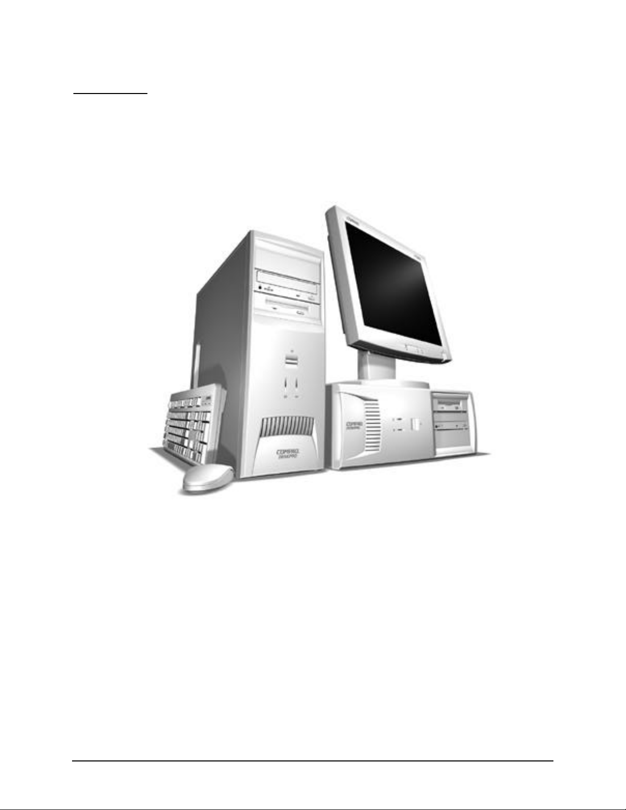
This chapter describes the model offerings and features of Compaq Deskpro EP Series of
Personal Computers.
Compaq Deskpro EP Series of Personal Computers
Compaq Deskpro EP Series of Personal Computers 1-1
Page 10

1.1 Model Overview
Compaq Deskpro EP Series of Personal Computers ship as either desktop or minitower
models. They contain the unique, flexible Compaq ATX chassis, which allows you to
easily reconfigure the unit as a minitower by (1) removing the drives from the computer,
(2) standing the unit on its side, (3) rotating the drives and bezel blanks 90 degrees, then
(4) reinserting the drives into the drive bays.
✎
The Compaq Deskpro EP Series, Intel 440BX chipset models will be referred to
in this MSG as 440BX.
The Compaq Deskpro EP Series, Intel 810 chipset models will be referred to in
this MSG as 810 or Intel 810.
The Compaq Deskpro EP Series, Intel 810e chipset models will be referred to in
this MSG as 810e or Intel 810e.
1-2 Product Description
Page 11

1.2 System Design
! Desktop models of the Compaq Deskpro EP Series of Personal Computers use an
innovative chassis to house the removable system board, expansion boards, power
supply, and mass storage devices.
Internal components are accessible when the access panel is removed.
!
The front bezel is a multi-part assembly that attaches to the chassis with release
!
latches. Attached to the back of the front bezel is a subpanel that holds the bezel
blanks.
! The system board may be removed from the chassis after the access panel is
removed. Details of the disassembly procedure are found in Chapter 4, “Removal
and Replacement Procedures.”
! The drive bays are located in the front of the chassis; there are two 3.5-inch drive
bays for internal hard drives and three 5.25-inch drive bays for accessible mass
storage.
The chassis design allows drive installation without the use of rails. Guide screws
!
installed on each side of the drive ensures its proper alignment within the drive
bay. Extra guide screws are provided in the front of the chassis.
! The desktop model of this computer may be converted to a minitower
configuration. See Chapter 4, “Removal and Replacement Procedures,” for
additional information and instructions.
Detailed descriptions of the system components are presented in the sections that follow.
Compaq Deskpro EP Series of Personal Computers 1-3
Page 12

1.3 Preinstalled Software
This computer ships with Windows 95, Windows 98, or Windows NT 4.0 installed as the
operating system, and also contains the following preloaded software:
ROM-based Setup utilities
!
Compaq Diagnostics for Windows
!
! Compaq support software and device drivers
! Online
! Intelligent Manageability
! Power Management with Energy Saver features
! Security Management
! Remote Management Tools
! Microsoft Internet Explorer
Safety & Comfort Guide
1.3.1 Ordering Additional Software
If you plan to run any of the following operating systems on the computer, you must
install the corresponding Compaq device drivers and utilities before attempting to use the
computer:
IBM OS/2
!
! NetWare
! Microsoft Windows NT Workstation 3.51 or 4.0
A version of Microsoft Windows 95 that is different from the one included with
!
the computer
To order copies of suitable device drivers and utilities:
Order the
!
contains the latest device drivers, utilities, and flashable ROM images needed to
run MS-DOS, Windows 3.1, Windows 95, Windows NT Workstation 3.51, IBM
OS/2, and NetWare on the Compaq commercial desktop product.
Support Software CD for Compaq Desktop Products.
(English only)
This compact disc
! Download the software from the Compaq World Wide Web site
(www.compaq.com).
Purchase backup diskettes.
!
The
Support Software CD
A single CD-ROM that gives one-time access to the latest support software (North
!
America only).
! A yearly subscription that delivers up to 12 monthly CD-ROMs.
The annual subscription provides continuous access to the latest developments.
✎
1-4 Product Description
can be purchased in either of two ways:
When calling Compaq to place an order, be sure to have the serial number of the
computer available. This number is necessary for all purchases.
Page 13
1.4 Computer Features
Compaq Deskpro EP Series of Personal Computers ship with a mouse and keyboard.
Some models are also equipped with a CD-ROM drive. A Compaq color monitor or other
compatible monitor does not ship with the computer.
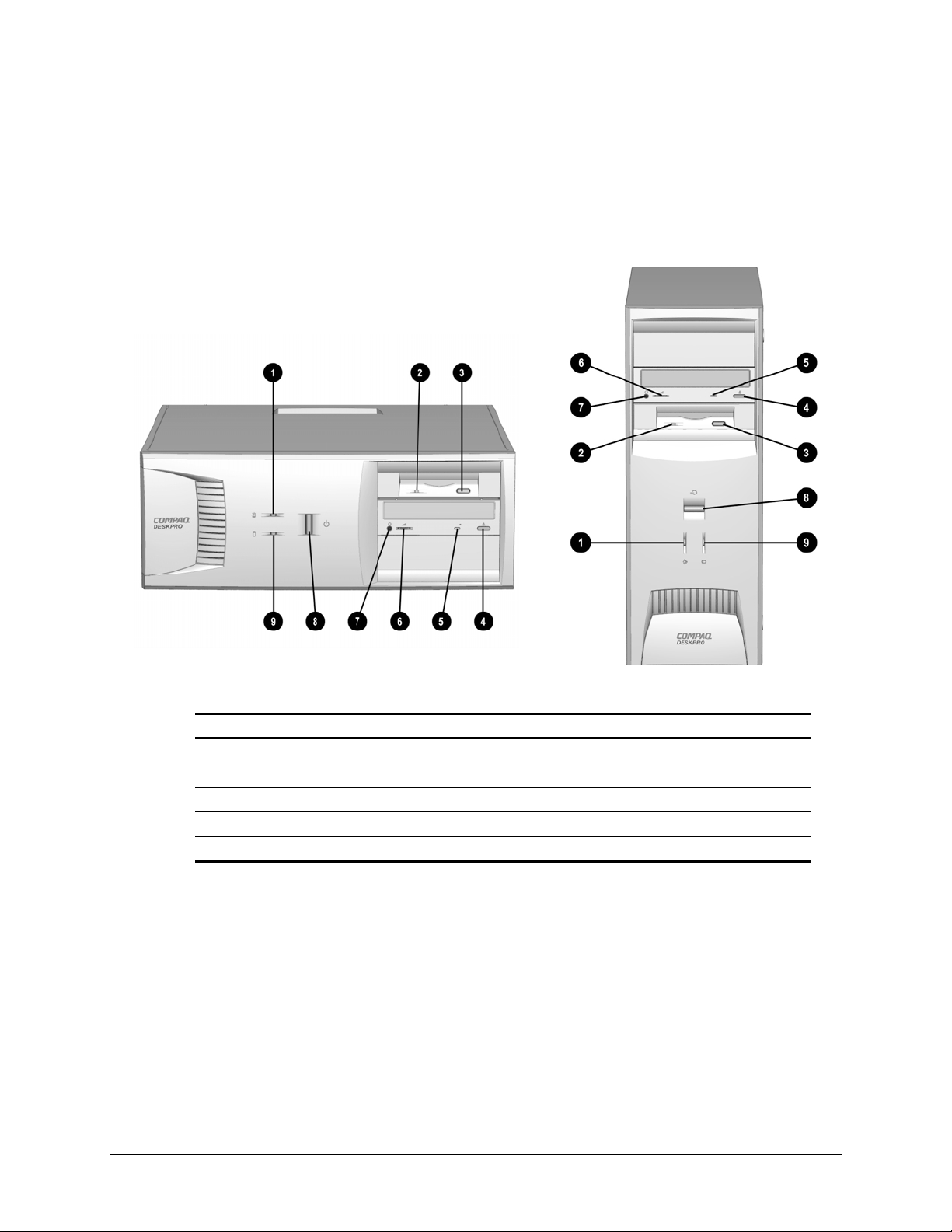
1.4.1 Front Panel Controls and LEDs - 440BX
Front Panel Controls and LEDs - 440BX
Ref. Component/Function Ref. Component/Function
Power-On Light
1
Diskette Drive Activity Light
2
Diskette Eject Button
3
CD-ROM Eject Button*
4
CD-ROM Activity Light*
5
*CD-ROM models only.
**Flashes when an ATAPI device, such as the hard drive, is active.
6
7
8
9
CD-ROM Volume Control*
CD-ROM Headphone Jack*
Dual-State Power Button
Drive Activity Light**
Compaq Deskpro EP Series of Personal Computers 1-5
Page 14
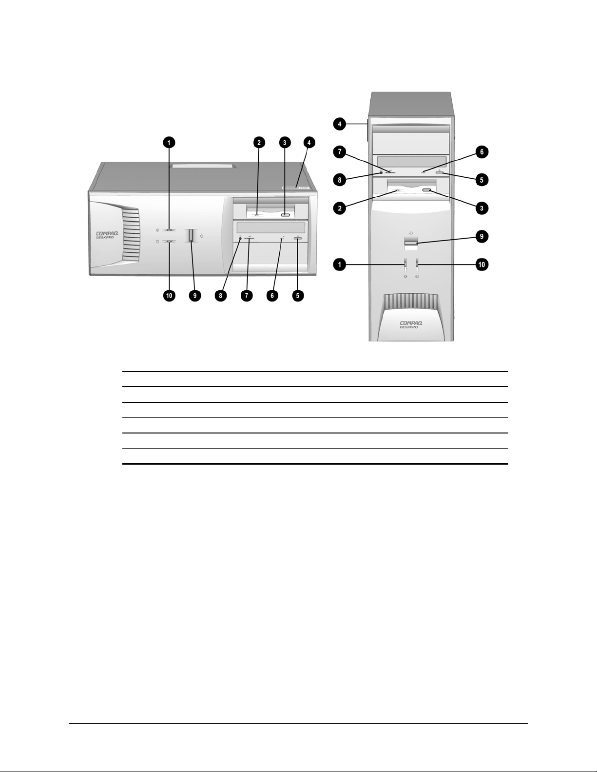
1.4.2 Front Panel Controls and LEDs - Intel 810/810e
Front Panel Controls and LEDs - Intel 810/ 810e
Ref. Component/Function Ref. Component/Function
Power-On Light
1
Diskette Drive Activity Light
2
Diskette Eject Button
3
Serial Number
4
CD-ROM Eject Button*
5
*CD-ROM models only.
**Flashes when an ATAPI device, such as the hard drive, is active.
6
7
8
9
:
CD-ROM Drive Busy Indicator*
Headphone Volume Control
Stereo Headphone Jack
Dual-State Power Button
Drive Activity Light**
1-6 Product Description
Page 15
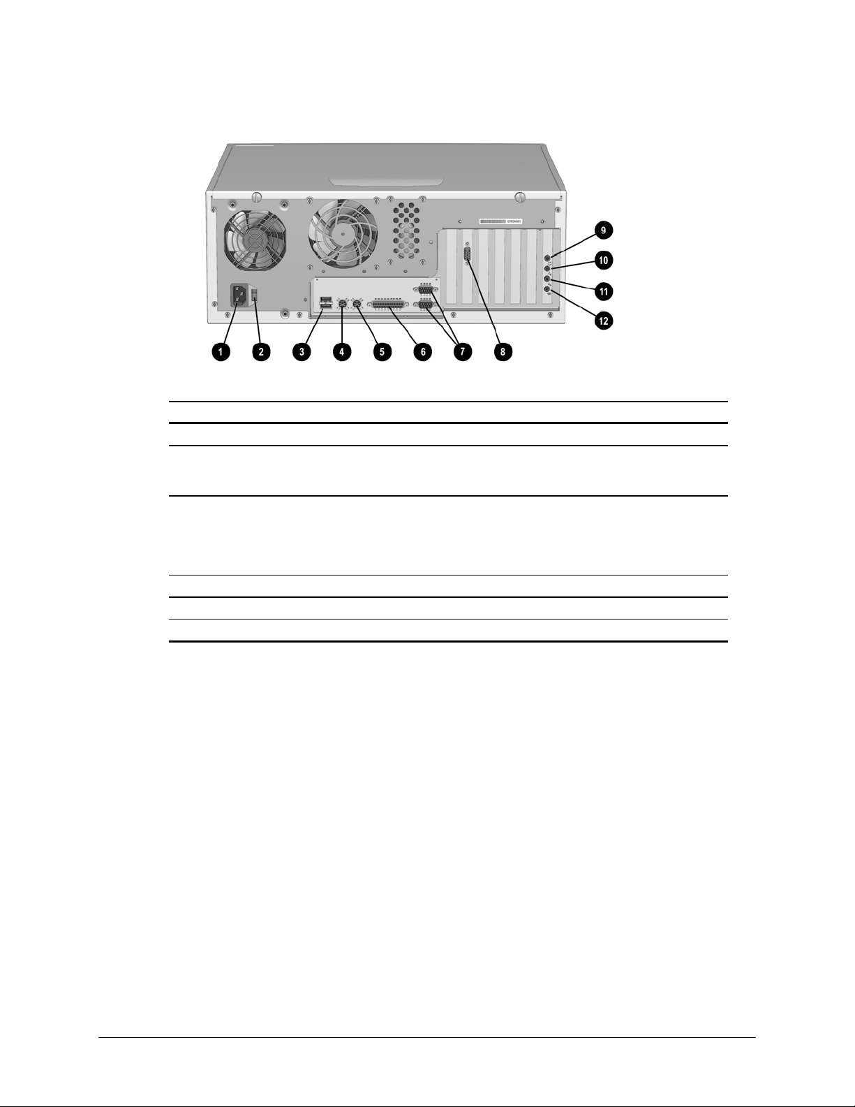
1.4.3 Rear Panel Connectors - 440BX
Rear Panel Connectors - 440BX
Ref. Component Component
Power Cord Connector
1
Voltage Select Switch (switches
2
voltage between 115V and 230V to
match geographical requirements)
Universal Serial Bus (USB)
3
Connectors (2) (connects the
computer to any USB peripheral while
the computer is operating; is a fully
functional plug and play connector)
Keyboard Connector
4
Mouse Connector
5
Parallel Port Connector
6
Audio features are available on select models only.
*
7
8
9
:
;
<
Serial Connectors (2)
Monitor Connector
Headphone Connector*
Line-Out Audio Connector*
Line-In Audio Connector*
Microphone Connector *
Compaq Deskpro EP Series of Personal Computers 1-7
Page 16
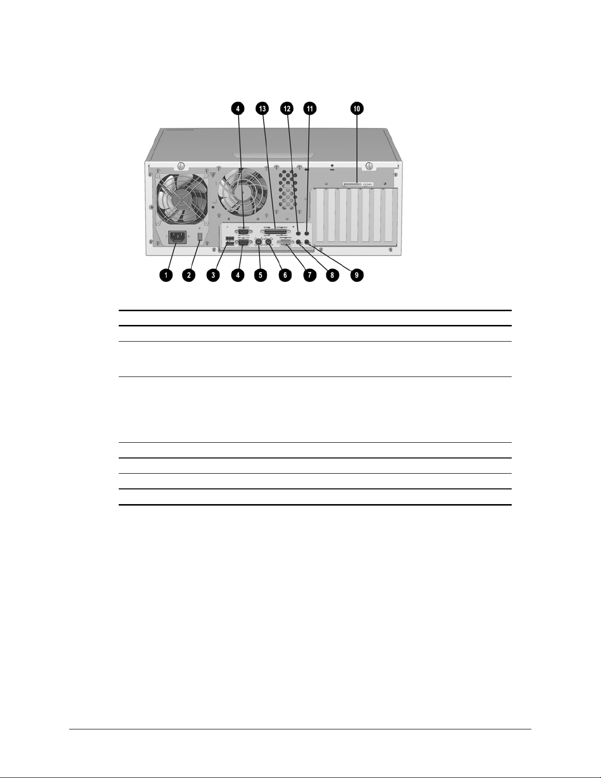
1.4.4 Rear Panel Connectors - Intel 810/810e
Rear Panel Connectors - Intel 810/810e
Ref. Component Ref. Component
Power Cord Connector
1
Voltage Select Switch (switches
2
voltage between 115V and 230V to
match geographical requirements)
Universal Serial Bus (USB)
3
Connectors (2) (connects the
computer to any USB peripheral
while the computer is operating; is
a fully functional plug and play
connector)
Serial Connectors
4
Keyboard Connector*
5
Mouse Connector*
6
Monitor Connector
7
*Keyboard and mouse ports are interchangeable
8
9
:
;
<
=
Headphone Connector
Line-Out Audio Connector
Serial Number
Line-In Audio Connector
Microphone Connector
Parallel Port Connector
1-8 Product Description
Page 17
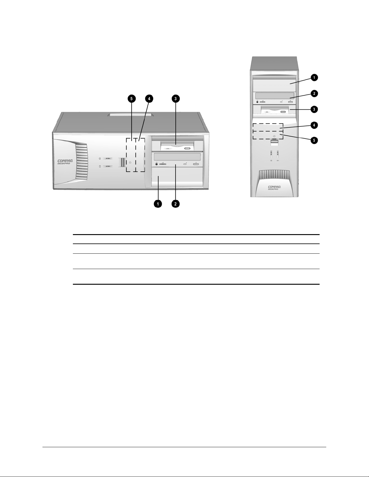
1.4.5 Drive Positions
Drive Positions
Reference Drive Bay Configuration
1, 2
3
4, 5
✎
1, 2 Two standard 5.25-inch, half-height bays for optional drives
3 One standard 3.5-inch, 1.44-MB diskette drive mounted with a drive
adapter into a 5.25-inch bay
4, 5 Two standard 3.5-inch drive bays; Bay 4 contains the preinstalled hard
drive; Bay 5 is available for an optional hard drive
Drive bay numbers are stamped on the chassis.
To verify the type and size of the mass storage devices installed in the computer, run
Compaq Computer Setup.
Compaq Deskpro EP Series of Personal Computers 1-9
Page 18
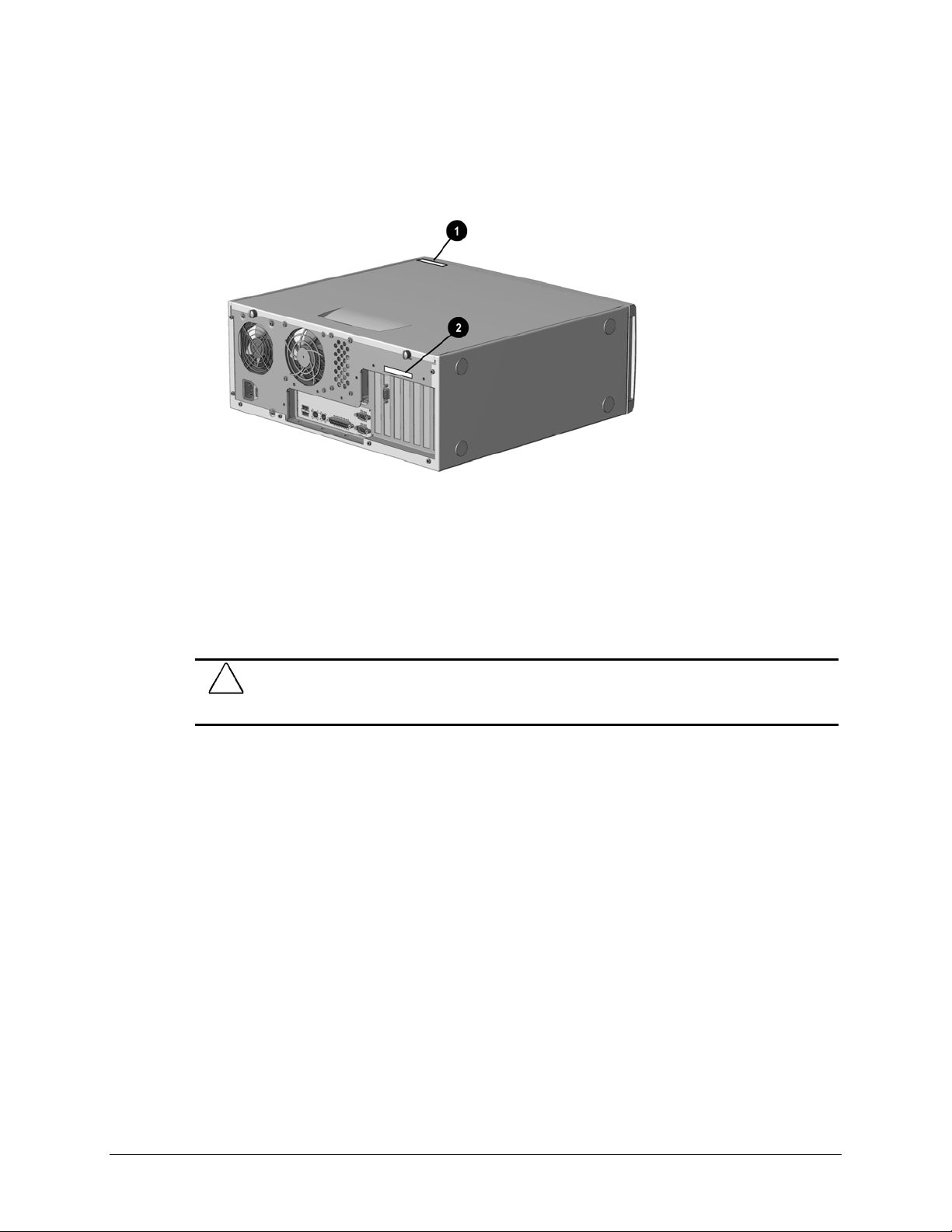
1.5 Serial Number Location
The serial number and model information label is located on the access panel of the
unit 1. A second barcode label is located on the rear of the unit 2.
Serial Number Locations
For the purpose of AssetControl, the serial number is embedded in CMOS and in the
EEPROM on the system board and may be accessed through Diagnostics for Windows.
✎
The computer serial number should be provided to Compaq when requesting information
or ordering spare parts.
If the system board is replaced with a spare part from Compaq, the invalid serial
number condition will be recognized during POST. The original serial number
must then be reentered through Computer Setup. Refer to the Software Reference
Guide for more information.
CAUTION:
number and will create a mismatch between the serial number label and the electronic serial
number.
A system board borrowed from another computer is recognized as a valid serial
1-10 Product Description
Page 19
chapter
2
SPARE P ARTS
Compaq Deskpro EP Series of Personal Computers
.
Compaq Despro EP Series of Personal Computers 2-1
The Compaq Deskpro EP Series, Intel 440BX chipset models will be referred to
in this MSG as 440BX.
The Compaq Deskpro EP Series, Intel 810 chipset models will be referred to in
this MSG as 810 or Intel 810.
The Compaq Deskpro EP Series, Intel 810e chipset models will be referred to in
this MSG as 810e or Intel 810e.
Page 20
2.1 System Unit
2.1.1 System Unit - 440BX
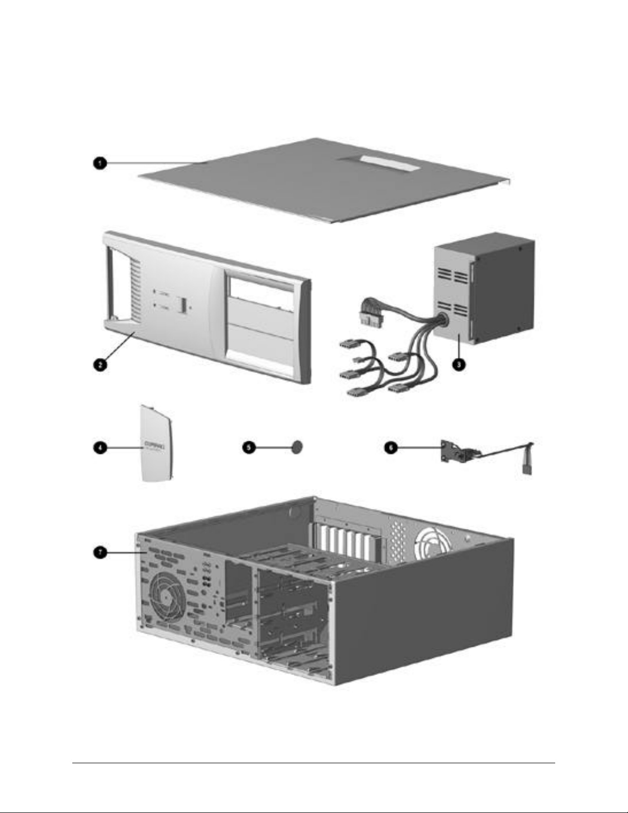
System Unit Spare Parts - 440BX Model
2-2 Spare Parts
Page 21

System Unit Spare Parts - 440BX
Description Spare Part Number
1 Access panel 166867-001
2 Front bezel, complete with subpanel and bezel blanks 166868-001
3 Power supply, 200 Watt 166814-001
3 Power supply, 145 Watt 332863-001
4 Logo Kit, Deskpro EP (1 ea., DT and MT) 166924-001
5 Feet Miscellaneous Plastics
6 Power switch with cable, LED and switch holder (3 ea.) 166925-001
7 Chassis/basepan (repair/exchange only) 166880-001
Major Differences Between 440BX and Intel 810/810e
System
Board
Assembly
440BX, PII,
two-DIMM model,
332857-001
(PCA 008312-101)
440BX, PII,
three-DIMM model,
166813-001
(PCA 009635-101)
440BX, PII/PIII,
three-DIMM model
118053-001
(PCA 010233-101)
Date code of
X908XXXXXXXX or later
440BX, PIII
three-DIMM model
164483-001
(PCA 010582-101)
Intel 810, Celeron
401963-001
(PCA 010174-101)
Intel 810e, Celeron
164122-001
(PCA 010546-101)
Intel 810e, Celeron
187672-001
(PCA 010697-101)
Power
Supply
145 Watt
332863-001 166814-001 166867-001 166880-001 166838-001
332863-001 166814-001 166867-001 166880-001 166838-001
332863-001 166814-001 166867-001 166880-001 166838-001
332863-001 166814-001 166867-001 166880-001 166838-001
n/a 103748-001 137384-001 Not spared 143218-001
n/a 103748-001 137384-001 Not spared 143218-001
174871-001 n/a 137384-001 Not spared 143218-001
Power
Supply
200 Watt
Access
Panel
Chassis
Assembly
Diskette
Drive
Cable
Compaq Despro EP Series of Personal Computers
2-3
Page 22
2.1.2 System Unit - Intel 810/810e
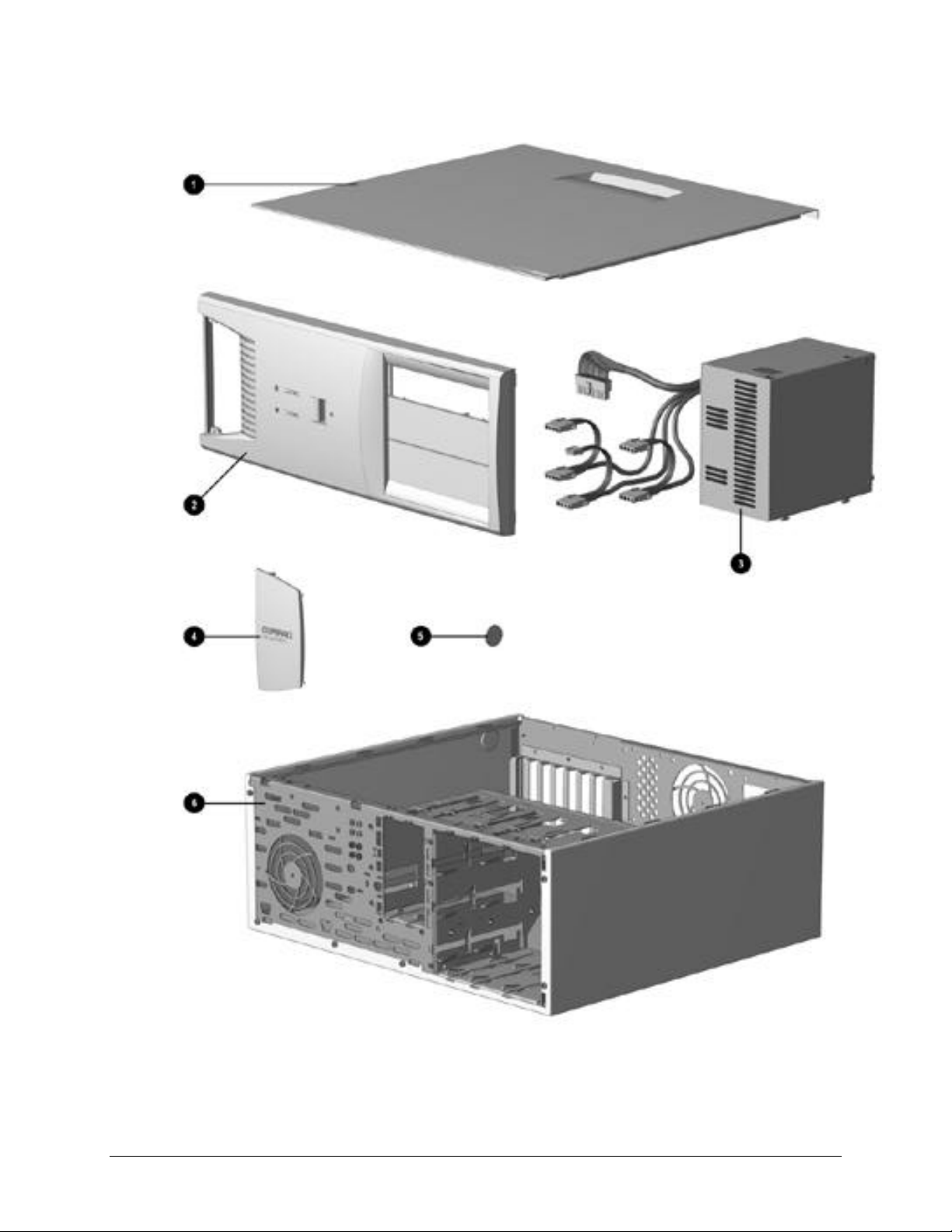
System Unit Spare Parts - Intel 810/810e Model
2-4 Spare Parts
Page 23

System Unit Spare Parts - Intel 810/810e
Description Spare Part Number
1 Access panel (includes gasket) 137384-001
2 Front bezel, complete with subpanel and bezel blanks 166868-001
3 Power supply, 200W 103748-001
* Power supply, 145W (only used with PCA 010697-101) 174871-001
4 Logo Kit, Deskpro EP (1 ea., DT and MT) 166924-001
5 Feet Miscellaneous Plastics
6 Chassis/basepan (repair/exchange only) Not spared
*Not Shown
Major Differences Between 440BX and Intel 810/810e
System
Board
Assembly
440BX, PII,
two-DIMM model,
332857-001
(PCA 008312-101)
440BX, PII,
three-DIMM model,
166813-001
(PCA 009635-101)
440BX, PII/PIII,
three-DIMM model
118053-001
(PCA 010233-101)
Date code of
X908XXXXXXXX or later
440BX, PIII
three-DIMM model
164483-001
(PCA 010582-101)
Intel 810, Celeron
401963-001
(PCA 010174-101)
Intel 810e, Celeron
164122-001
(PCA 010546-101)
Intel 810e, Celeron
187672-001
(PCA 010697-101)
Power
Supply
145 Watt
332863-001 166814-001 166867-001 166880-001 166838-001
332863-001 166814-001 166867-001 166880-001 166838-001
332863-001 166814-001 166867-001 166880-001 166838-001
332863-001 166814-001 166867-001 166880-001 166838-001
n/a 103748-001 137384-001 Not spared 143218-001
n/a 103748-001 137384-001 Not spared 143218-001
174871-001 n/a 137384-001 Not spared 143218-001
Power
Supply
200 Watt
Access
Panel
Chassis
Assembly
Diskette
Drive
Cable
Compaq Despro EP Series of Personal Computers
2-5
Page 24
2.2 Mass Storage Devices
Mass Storage Devices
2-6 Spare Parts
Page 25

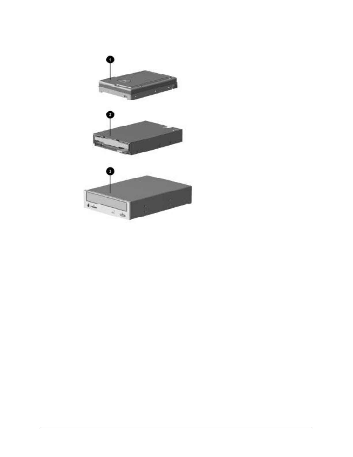
Mass Storage Devices
Description Spare Part Number
1 2.1-GB Ultra ATA hard drive (33/5400) 332861-001
* 3.2-GB Ultra ATA hard drive (33/5400) 332866-001
* 4.3-GB Ultra ATA hard drive (33/5400) 327646-001
* 4.3-GB Ultra ATA hard drive (66/5400) 134197-001
* 5.1-GB Ultra ATA hard drive (33/5400) 166872-001
* 6.4-GB Ultra ATA hard drive (33/5400) 166973-001
* 6.4-GB Ultra ATA hard drive (66/5400) 134198-001
* 10.0-GB Ultra ATA hard drive (33/5400) 320662-001
* 10.0-GB Ultra ATA hard drive (66/7200) 135364-001
* 10.0-GB Ultra ATA hard drive (66/5400) 134193-001
* 13.5-GB Ultra ATA hard drive (66/7200) 140515-001
* 15.0-GB Ultra ATA hard drive (33/7200) 120419-001
* 20.0-GB Ultra ATA hard drive (33/7200) 120420-001
* 22.6-GB Ultra ATA hard drive (33/7200) 388511-001
2 Diskette drive, 3.5-inch (141087-705), 1.44-MB, 3-mode, 1/3-
height, without bezel, includes drive bay adapter (179026-002)
* Diskette drive adapter 180808-001
3 24X Max tray load IDE CD-ROM drive 166869-001
* 32X Max tray load IDE CD-ROM drive 327659-001
* 40X Max tray load IDE CD-ROM drive 400807-001
* 52X Max tray load IDE CD-ROM drive 120696-001
* 60X Max tray load IDE CD-ROM drive 134195-001
* 8X DVD Drive 134196-001
*Not shown
(nn/nnnn) = hard drive transfer rate (MBytes/sec)/RPM
179161-001
. The increased speed of the Ultra ATA/66 drive is realized only on the Deskpro
EP Intel 800 series.
Ultra ATA/66 hard drives are backwards compatible with Ultra ATA/33 devices;
however, the data transfer rate is reduced to 33MB/sec.
Compaq Despro EP Series of Personal Computers 2-7
Page 26
2.3 Cables
Cables
2-8 Spare Parts
Page 27

Cables
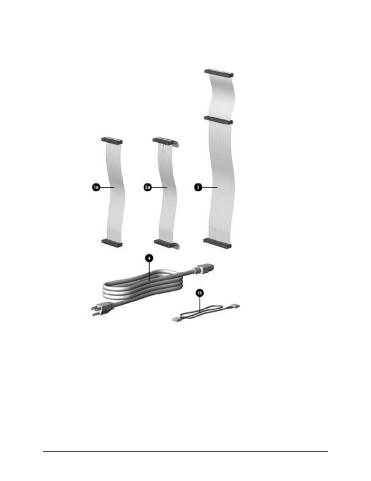
Description Spare Part Number
Cable Kit includes: 166879-001
1a Diskette drive cable without twist, 11”
440BX only, (166838-001)
1b Audio cable, 21”, (288489-002)
* IDE hard drive cable, 7”
* IDE hard drive/CD-ROM cable, 14”
2a Diskette drive cable with twist, 11”, with pull tab,
* IDE Ultra ATA hard drive/CD-ROM cable, 10”, with pull tab,
* Switch mounting bracket (3 ea.), (166777-001)
* Dual-LED power cable (1 ea.), (387727-001)
* 40-position data cable, 12.5” (105876-001)
* Diskette drive/tape cable, with twist, no key, 34”
* RTF card for EP diskette drive cable (157354-001)
* Diskette drive cable with twist, 11”, without pull tab
3 Cable, IDE CD-ROM/hard drive, 14-inch, 80-conductor 278296-001
4 Power cord, AC, black (US, LA, Asia/Pacific, Brazil) 142766-001
* NIC Remote Wakeup cable 166974-001
* Power switch with cable and switch mounting bracket
* Audio cable, 25”.
* Video cable for P1610W color monitor 305717-001
*Not shown
440BX only, (247116-001)
440BX only, (242947-001)
Cable Kit (use on Intel 800 series products) includes: 166879-002
center polarization (143218-001)
center polarization, (108950-007)
Opt. (356107-001)
(387795-001)
(440BX and 810e PCA=010697-101 only) (3 ea.)
Use with Creative Labs SoundBlaster PCI 128V Audio Board.
166925-001
149806-001
Compaq Despro EP Series of Personal Computers 2-9
Page 28
2.4 Standard and Optional Boards
Standard and Optional Boards
2-10 Spare Parts
Page 29

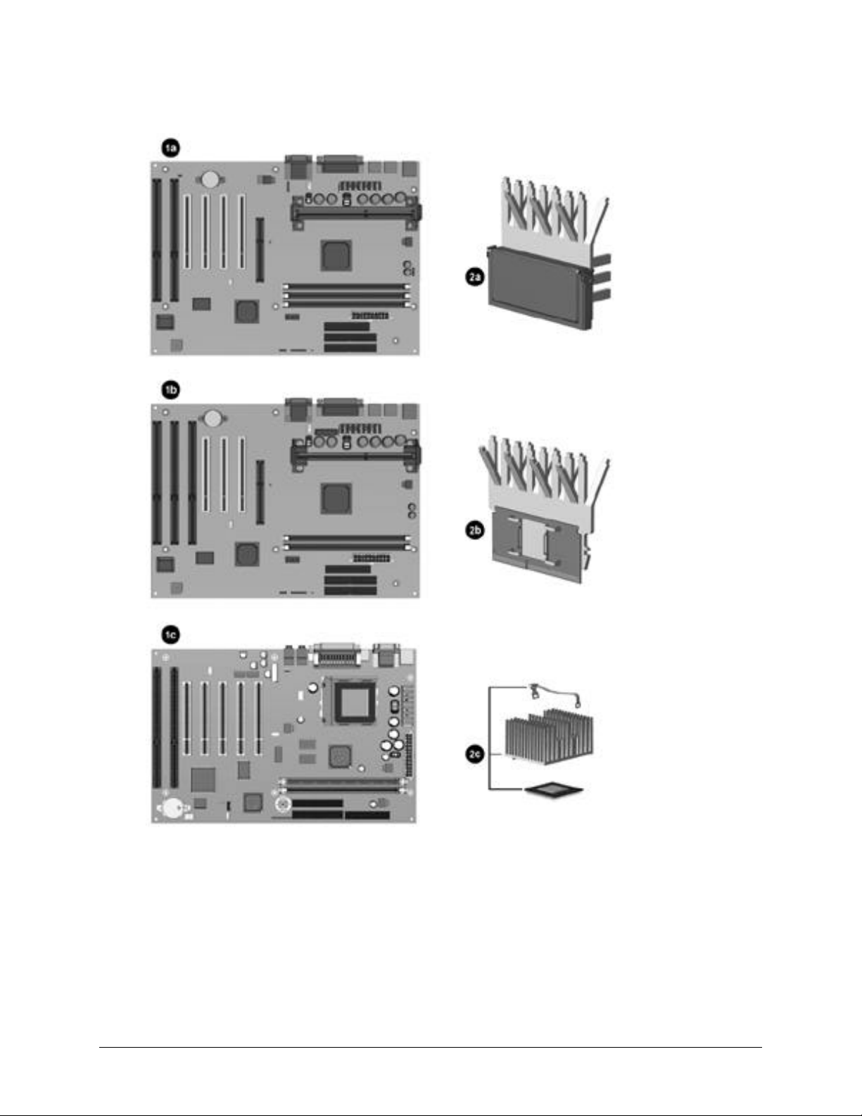
Standard and Optional Boards
Description Spare Part Number
1a PII System board, three-DIMM model (440BX)
(PCA=009635-101).
1b
PII System board, two-DIMM model (440BX)
(PCA=008312-101).
PII/PIII System board, three-DIMM model (440BX)
*
(PCA=010233-101) Shipped on all PII and PIII units after 2/23/99).
1c Intel 810 System Board (PCA=010174-101). 401963-001
* Intel 810e System Board (PCA=010546-101). 161422-001
* Intel 810e System Board (PCA=010697-101). 187672-001
* PIII System board, three-DIMM model (440BX)
(PCA=010582-101).
2b Processor, Intel Celeron 266/66 w/heatsink. Use on 2-DIMM board). 332858-001
Processor, Celeron 300A/66 w/heatsink. 356136-001
*
Processor, Celeron 333/66 w/heatsink. 356082-001
*
Processor, Celeron 366/66 w/28K cache, heatsink. 103253-001
*
Processor, Celeron 400/66 w/128K cache, heatsink. 402126-001
*
2c Processor, Celeron 466/66 (includes heatsink, clip, and
thermal crayon). Use on 010174-101 system board.
* Processor, Celeron 466/66 (401264-006), w/heatsink, clip, and
thermal interface. Use on 010697-101 system board.
Processor, Celeron 500/66 w/heatsink. Use on 010174-101
*
system board.
* Processor, Celeron 500/66 (401264-007), w/heatsink, clip, and
thermal interface). Use on 010697-101 system board.
Processor, PII 266/66 w/heatsink. 332862-001
*
Processor, PII 300/66 w/heatsink. Use on 2-DIMM board. 166881-001
*
Processor, PII 333/66 w/heatsink. 166887-001
*
2a Processor, PII 350/100 w/heatsink. Use on 3-DIMM board. 166874-001
Processor, PII 400/100 w/heatsink. Use on 3-DIMM board. 166882-001
*
Processor, PII 450/100 w/heatsink. 167032-001
*
Processor, PIII, 450/100 (352772-004) w/heatsink (401405-001)
*
and thermal compound (243199-002). Use on 010233-101 system
board.
Processor, PIII, 450/100 (352772-004) w/heatsink (401405-003),
*
keyed heatsink clip (120891-001), and retention mechanism
(350767-005). Use on 010546-101 system board.
Processor, PIII, 500/100 (352772-005) w/heatsink (401405-001),
*
and thermal compound (243199-002). Use on 010233-101
system board.
Processor, PIII, 500/100 (352772-005), w/heatsink (401405-003),
*
keyed heatsink clip (120891-001), and retention mechanism
(350767-005). Use on 010546-101 system board.
Processor, PIII, 500/100 (158353-001), w/heatsink, clip, and thermal
*
interface. Use on 010697-101 system board.
*Not shown
166813-001
332857-001
118053-001
164483-001
103747-001
176740-001
155379-001
176741-001
122735-001
164400-001
116401-001
164401-001
176742-001
Continued
#
2-11
Page 30
Standard and Optional Boards, continued
2-12 Spare Parts
Page 31

Standard and Optional Boards Continued
101 system
atsink, clip, and thermal
Description Spare Part Number
Processor, PIII, 533/133, (137365-003), w/heatsink (401405-003),
*
keyed heatsink clip (120891-001), spacer (168092-001), retention
mechanism (350767-005). Use on 010546-101 system board.
Processor, PIII, 550/100 (352772-006), w/heatsink (401405-001),
*
and thermal compound (243199-002). Use on 010233-
board.
Processor, PIII, 550/100 (158353-002), w/he
*
interface. Use on 010697-101 system board.
* Processor, PIII, 600/133, (137365-001), w/heatsink (401405-003),
keyed heatsink clip (120891-001), spacer (168092-001), retention
mechanism (350767-005). Use on 010546-101 system board.
Processor, PIII, 600/133 (158807-002), w/heatsink, clip,
*
and thermal interface. Use on 010697-101 system board.
Processor, PIII, 600/100, (352772-007), w/heatsink (135638-001).
*
Use on 010233-101 system board.
*
Processor, PIII, 650/100 (157381-002), w/heatsink (401405-003),
keyed heatsink clip (120891-001, spacer (168092-001), retention
mechanism (350767-005). Use on 010582-101 system board.
*
Processor, PIII, 667/133, (137365-002), w/heat sink (401405-003),
keyed heatsink clip (120891-001, spacer (168092-001), retention
mechanism (350767-005). Use on 010546-101 system board.
*
Processor, PIII, 700/100 (157381-004), w/heatsink (401405-003),
keyed heatsink clip (120891-001, spacer (168092-001), retention
mechanism (350767-005). Use on 010582-101 system board.
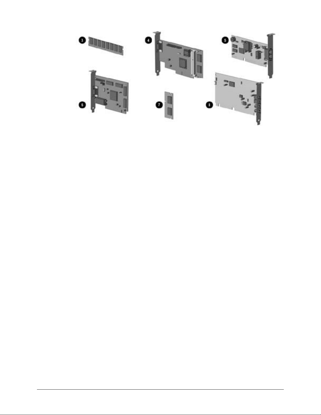
3 Memory Module, DIMM, 66 MHz
16-MB 278066-001
* 32-MB 278067-001
* 64-MB 278095-001
* Memory Module, DIMM, 66 MHz with ECC
16-MB 278097-001
32-MB 288440-001
64-MB 278098-001
128-MB 278099-001
* Memory Module, DIMM, 100 MHz
16-MB 166969-001
32-MB 166890-001
64-MB 179190-001
128-MB 166966-001
* Memory Module, DIMM, 100 MHz with ECC
16-MB 166964-001
32-MB 166968-001
64-MB 166967-001
128-MB 166965-001
164402-001
133840-001
176743-001
164403-001
176744-001
155592-001
164568-001
161671-001
164568-001
Compaq Despro EP Series of Personal Computers 2-13
Page 32

Standard and Optional Boards Continued
Description Spare Part Number
4 ATI RAGE PRO GRAPHICS 1X 166871-001
ATI RAGE PRO GRAPHICS 2X 166970-001
*
ATI RAGE PRO GRAPHICS IIC 332865-001
*
Matrox MGA G100 AGP graphics board 328011-001
*
Matrox Millenium G200-SD graphics card with 8-MB memory
*
402125-001
(shipped on all PII and PIII units after 2/23/99)
Matrox Millenium G200-SD graphics card with 8-MB memory
*
167033-001
* Matrox Millenium G400 graphics card with 16-MB memory 400437-001
5 33.6k Modem 294912-001
56k Modem 292269-003
*
6 NVIDIA Graphics 166982-001
7 ATI Graphics memory upgrade, 2-MB for use on 166871-001 166971-001
ATI Graphics memory upgrade, 4-MB for use on 166970-001 166972-001
*
8 ESS 1869 ISA Audio Board (440BX). Use on speaker 166507-001 332859-001
Creative Labs SoundBlaster PCI 128V Audio Board with Compaq
*
167984-001
PREMIER•SOUND (440BX)
Shipped on 440BX units with Windows 98 or Windows NT 4.0 and
• PIII 650/100 and 700/100 starting 11/15/99
• PIII 500-MHz and greater starting 11/17/99
Compaq 10/100 TX PCI Intel WOL UTP w/Remote Wakeup cable 323553-001
*
3-COM PCI, 10/100 WOL 179167-001
*
* Compaq PREMIER•SOUND board
356081-001
(for use with speaker 167029-001)
*Not shown
2-14 Spare Parts
Page 33

2.5 Keyboards
Description Spare Part Number
* Arabic 269513-171
* Belgian 269513-181
* Brazilian 269513-201
* BHCSY (Bosnia-Herzegovina, Croatia, Slovenia, and
Yugoslavia)
* Czech 269513-221
* Danish 269513-081
* Finnish 269513-351
* French 269513-051
* French Canadian 269513-121
* German 269513-041
* Greek 269513-151
* Hungarian 269513-211
* Italian 269513-061
* Japanese 269513-191
* Korean (Hanguel) 269513-AD1
* International 269513-B31
* Latin American Spanish 166984-161
* Norwegian 269513-091
* Polish 269513-241
* Portuguese 269513-131
* Russian 269513-251
* Slovakian 269513-231
* Spanish 269513-071
* Swedish 269513-101
* Swiss 269513-111
* Taiwanese 269513-AB1
* Thai 269513-281
* Turkish 269513-141
* UK 269513-031
* US 166984-001
*Not shown
Keyboards
269513-B41
Compaq Despro EP Series of Personal Computers 2-15
Page 34

2.6 Miscellaneous Hardware Kit
Miscellaneous Hardware Kit
Miscellaneous Hardware
Description Spare Part Number
Miscellaneous hardware kit. Includes: 166877-001
1 Cover, slot (5 ea.) (101144-001)
2a I/O Panel for 440BX (166802-002)
2b I/O Panel for Intel 810/810e (123556-001)
* I/O Panel for Intel 810e – PCA=010697-101 (166808-002)
3 Fan guard (105427-003)
4 Screw, 6/32 pan head x 1/4 inch (4 ea.) (192308-001)
5 Thumbscrew (2 ea.) (440BX) (197436-001)
* Thumbscrew (2 ea.) (Intel 810/810e) (124702-001)
6 Screw, M3 x 0.25 inch (4 ea.) (247348-001)
* Plastite flathead screw (4 ea.) (247481-001)
* Plastic push lock fastener for fan assy (4 ea.) (118663-002)
* Bracket (270886-002), blank, AGP
* Gasket (247347-072)
(for use on 101144-001 slot cover inserted in 7th slot)
* Gasket (304477-037)
(for use on Int el 810 access panel, 137384-001)
*Not shown
2-16 Spare Parts
Page 35

2.7 Miscellaneous Plastics Kit
Miscellaneous Plastics Kit
Miscellaneous Plastics Kit, Desktop and Minitower
Description Spare Part Number
Miscellaneous plastics kit includes: 166878-001
1 Diskette bezel (166776-001)
2 Foot, rubber (4 ea.) (166939-002)
3 Processor retainer with pins for PII processor (166889-002)
(No longer included in kit)
4 Processor retainers with pins for Celeron processor (2 ea.)
(332816-001) (No longer included in kit)
* Processor retainer for PII and Celeron processor
(350767-001)
5 Bezel, blank (2 ea.) (166775-001)
6 Panel, sub (166835-001)
7 Button, power (166774-001)
8 Spring, power button (166837-001)
9 Drivelock, DT (166779-001)
10 Drivelock, MT (166780-001)
11 Springs, drivelock (2 ea.) (166837-002)
12 Board guide (166778-001)
*Not shown
Compaq Despro EP Series of Personal Computers 2-17
Page 36

2.8 Miscellaneous Parts
450/100 and above and all Pentium III units 450/100 and above)
Miscellaneous Parts
Miscellaneous Parts
1 Two-button mouse 166861-001
* Compaq Intellimouse 317863-001
2 Cable lock bracket 199109-001
3 Battery (440BX) 234556-001
* Battery (Intel 810)
(for use on system board 401963-001)
4 Fan assembly with four plastic pins (for use on Pentium II units
153099-001
166922-001
2-18 Spare Parts
* Chassis fan cover 166847-001
5a Speaker with screws (50mm x 90mm, 5 watt)
(440BX) (for use on audio board 356081-001)
5b Speaker with screws (2.5”, 5 watt) (440BX)
(for use on audio board 332859-001)
* Speaker (40mm x 70mm), (Intel 810) (356080-002) 158267-001
* Speaker (40mm x 70mm), (Intel 810e) (174920-001) 180809-001
6 Power switch with cable and switch mounting bracket
(440BX only), (3 ea.)
7 3.5- to 5.25-Inch diskette drive mounting bracket with screws
and brace for use in bay 3 only. (440BX only)
* 3.5- to 5.25-Inch hard drive mounting bracket 243231-001
* 3.5- to 5.25-Inch ½ height mounting bracket for use in bays
1 and 2 only
*Not shown
167029-001
166507-001
166925-001
166923-001
243230-002
Page 37

2.9 Shipping Boxes
Shipping Boxes (not illustrated)
Description Spare Part Number
Return Kit with buns (U.S.) 166990-001
Return Kit (international) 166990-002
2.10 Documentation and Software
Documentation and Software (not illustrated)
Description Spare Part Number
Maintenance & Service Guide (desktop & minitower) 180999-001
Deskpro Service Reference Guide 152611-001
Windows 98 Country Kit 165534-001
Windows 95 Country Kit 165535-001
Windows NT Country Kit 165536-001
Compaq Despro EP Series of Personal Computers 2-19
Page 38

chapter
3
EMOVAL AND REPLACEMENT PRELIMINARIES
R
3.1 Routine Care
3.1.1 Cleaning Safety Precautions
! Never use solvents or flammable solutions to clean the computer.
Never immerse any parts in water or cleaning solutions; apply any liquids to a
!
clean cloth and then use the cloth on the component.
! Always turn off the computer when cleaning with liquids or damp cloths.
Always turn off the computer before cleaning the keyboard, mouse, or air vents.
!
! Disconnect the keyboard before cleaning it.
! Wear safety glasses equipped with side shields when cleaning the keyboard.
3.1.2 Cleaning the Computer Case
Follow all safety precautions in Section 3.1.1 before cleaning the computer.
! To remove light stains or dirt, use plain water with a clean, lint-free cloth or swab.
! For stronger stains, use a mild dishwashing liquid diluted with water. Rinse well by
wiping it with a cloth or swab dampened with clear water.
! For stubborn stains, use isopropyl (rubbing) alcohol. No rinsing is needed as the
alcohol will evaporate quickly and not leave a residue.
After cleaning, always wipe the unit with a clean, lint-free cloth.
!
Occasionally, clean the air vents on the computer. Lint and other foreign matter
!
can block the vents and limit the airflow.
Compaq Deskpro EP Series of Personal Computers 3-1
Page 39

3.1.3 Cleaning the Keyboard
Follow all safety precautions in Section 3.1.1 before cleaning the keyboard.
To clean the tops of the keys or the keyboard body, follow the procedures described in
Section 3.1.2.
When cleaning debris from under the keys, review all rules in Section 3.1.1 before
following these procedures:
CAUTION:
under the keys.
! Visible debris underneath or between the keys may be removed by vacuuming or
Use safety glasses equipped with side shields before attempting to clean debris from
shaking.
! Canned, pressurized air may be used to clean debris from under the keys. Caution
should be used as too much air pressure can dislodge lubricants applied under the
wide keys.
If you remove a key, use a specially designed key puller to prevent damage to the
!
keys. This tool is available through many electronic supply outlets.
CAUTION:
are improperly removed or installed, the keyboard may not function properly.
! Cleaning under a key may be done with a swab dampened with isopropyl alcohol.
Never remove a wide leveled key (like the space bar) from the keyboard. If these keys
Be careful not to wipe away lubricants necessary for proper key functions. Use
tweezers to remove any fibers or dirt in confined areas. Allow the parts to air dry
before reassembly.
3.1.4 Cleaning the Monitor
! Wipe the monitor screen with a clean cloth moistened with water or with a towlette
designed for cleaning monitors. Do not use sprays or aerosols directly on the
screen, the liquid may seep into the housing and damage a component. Never use
solvents or flammable liquids on the monitor.
! To clean the monitor body follow the procedures in Section 3.1.2.
3.1.5 Cleaning the Mouse
Before cleaning the mouse, ensure that the power to the computer is turned off.
Clean the mouse ball by first removing the retaining plate and the ball from the
!
housing. Pull out any debris from the ball socket and wipe the ball with a clean dry
cloth before reassembly.
To clean the mouse body, follow the procedures in Section 3.1.2.
!
3-2 Removal and Replacement Preliminaries
Page 40

3.2 Electrostatic Discharge Information
A sudden discharge of static electricity from your finger or other conductor can destroy
static-sensitive devices or microcircuitry. Often the spark is neither felt nor heard, but
damage occurs. An electronic device exposed to electrostatic discharge (ESD) may not be
affected at all and can work perfectly throughout a normal cycle. The device may function
normally for a while, then degrade in the internal layers, reducing its life expectancy.
Networks built into many integrated circuits provide some protection, but in many cases,
the discharge contains enough power to alter device parameters or melt silicon junctions.
3.2.1 Generating Static
The following table shows that different activities generate different amounts of static
electricity, and that static electricity increases as humidity decreases.
✎
Event 10% 40% 55%
Walking across carpet 35,000 V 15,000 V 7,500 V
Walking across vinyl floor 12,000 V 5,000 V 3,000 V
Motions of bench worker 6,000 V 800 V 400 V
Removing DIPs* from plastic tube 2,000 V 700 V 400 V
Removing DIPs* from vinyl tray 11,500 V 4,000 V 2,000 V
Removing DIPs* from Styrofoam 14,500 V 5,000 V 3,500 V
Removing bubble pack from PCB 26,500 V 20,000 V 7,000 V
Packing PCBs in foam-lined box 21,000 V 11,000 V 5,000 V
*Dual Inline Packaging (DIP) is the packaging around individual microcircuitry. These are then
multi-packaged inside plastic tubes, trays, or Styrofoam.
700 volts can degrade a product.
Relative Humidity
3.2.2 Preventing Electrostatic Damage to Equipment
Many electronic components are sensitive to ESD. Circuitry design and structure
determine the degree of sensitivity. The following proper packaging and grounding
precautions are necessary to prevent damage to electric components and accessories.
To avoid hand contact, transport products in static-safe containers such as tubes,
!
bags, or boxes.
Protect all electrostatic parts and assemblies with conductive or approved
!
containers or packaging.
Keep electrostatic sensitive parts in their containers until they arrive at static-free
!
stations.
! Place items on a grounded surface before removing them from their container.
Always be properly grounded when touching a sensitive component or assembly.
!
Avoid contact with pins, leads, or circuitry.
!
! Place reusable electrostatic-sensitive parts from assemblies in protective packaging
or conductive foam.
Compaq Deskpro EP Series of Personal Computers 3-3
Page 41

3.2.3 Personal Grounding Methods and Equipment
Use the following equipment to prevent static electricity damage to equipment:
Wrist straps are flexible straps with a minimum of one-megohm +/- 10% resistance
!
in the ground cords. To provide proper ground, a strap must be worn snug against
bare skin. The ground cord must be connected and fit snugly into the banana plug
connector on the grounding mat or workstation.
! Heel straps/Toe straps/Boot straps can be used at standing workstations and are
compatible with most types of shoes or boots. On conductive floors or dissipative
floor mats, use them on both feet with a minimum of one-megohm +/- 10%
resistance between the operator and ground.
Static Shielding Protection Levels
Method Voltage
Antistatic plastic 1,500
Carbon-loaded plastic 7,500
Metallized laminate 15,000
3.2.4 Grounding Workstations
To prevent static damage at the workstation, use the following precautions:
! Cover the workstation with approved static-dissipative material. Provide a wrist
strap connected to the work surface and properly grounded tools and equipment.
! Use static-dissipative mats, foot straps, or air ionizers to give added protection.
! Handle electrostatic sensitive components, parts, and assemblies by the case or
PCB laminate. Handle them only at static-free workstations.
! Turn off power and input signals before inserting and removing connectors or test
equipment.
! Use fixtures made of static-safe materials when fixtures must directly contact
dissipative surfaces.
Keep work area free of nonconductive materials such as ordinary plastic assembly
!
aids and Styrofoam.
Use field service tools, such as cutters, screwdrivers, and vacuums, that are
!
conductive.
3.2.5 Recommended Materials and Equipment
Materials and equipment that are recommended for use in preventing static electricity
include:
! Antistatic tape
Antistatic smocks, aprons, or sleeve protectors
!
Conductive bins and other assembly or soldering aids
!
Conductive foam
!
! Conductive tabletop workstations with ground cord of one-megohm +/- 10%
resistance
3-4 Removal and Replacement Preliminaries
Page 42

! Static-dissipative table or floor mats with hard tie to ground
! Field service kits
! Static awareness labels
! Wrist straps and footwear straps providing one-megohm +/- 10% resistance
! Material handling packages
Conductive plastic bags
!
Conductive plastic tubes
!
Conductive tote boxes
!
! Opaque shielding bags
! Transparent metallized shielding bags
! Transparent shielding tubes
3.3 Service Considerations
Listed below are some of the considerations that you should keep in mind during the
disassembly and assembly of the computer.
3.3.1 Tools and Software Requirements
! Compaq screwdriver with 8 bits, spare part number 161946-001
! Diagnostics software
3.3.2 Screws
The screws used in the computer are not interchangeable. They may have standard or
metric threads and may be of different lengths. If an incorrect screw is used during the
reassembly process, it can damage the unit. Compaq strongly recommends that all screws
removed during disassembly be kept with the part that was removed, then returned to their
proper locations.
3.3.3 Cables and Connectors
Most cables used throughout the unit are flat, flexible cables. These cables must be
handled with care to avoid damage. Apply only the tension required to seat or unseat the
cables during insertion or removal from the connector. Handle cables by the connector
whenever possible. In all cases, avoid bending, twisting, or tearing the cables, and ensure
that the cables are routed in such a way that they cannot be caught or snagged by parts
being removed or replaced.
CAUTION:
during the reassembly process. Improper cable placement can damage the computer.
When servicing this computer, ensure that cables are placed in their proper location
Compaq Deskpro EP Series of Personal Computers 3-5
Page 43

3.3.4 Hard Drives
! Handle hard drives as delicate precision components, avoiding all physical shock
and vibration. This applies to failed drives as well as replacement spares.
Use only the packaging provided by Compaq for shipping.
!
! Do not remove hard drives from the shipping package for storage. Keep hard
drives in their protective packaging until they are actually mounted in the CPU.
! Avoid dropping drives from any height onto any surface.
3.3.5 Plastic Parts
Plastic parts can be damaged by the use of excessive force during disassembly and
reassembly. When handling the plastic parts, use care.
3-6 Removal and Replacement Preliminaries
Page 44

chapter
4
EMOVAL AND REPLACEMENT PROCEDURES
R
This chapter provides general service information for the computer. Adherence to the
procedures and precautions described in this chapter is essential for proper service.
After completing all necessary removal and replacement procedures, run the Diagnostics
utility to verify that all components operate properly.
4.1 Disassembly Sequence Chart
Use the chart below to determine the disassembly sequence for removing components
from the computer.
4.3 Computer Feet
4.4 Logo Plate
4.5 Cable Lock
4.6 Access Panel
4.7 Front Bezel
4.8 Power Button
4.9 Subpanel and Bezel Blanks
4.10 Power Switch
4.11.1 Removing an Internal 3.5-Inch Hard Drive
4.11.2 Removing an External 5.25-Inch Drive
4.11.3 Removing an External 3.5-Inch Drive
4.12 Removing the Drivelocks
4.13.3 Removing an Expansion Board
4.14 Board Guide
4.15 System Memory
4.16.1 AGP Graphics Board Removal
4.16.2 AGP Graphics Memory Upgrade
4.17.1 Processor
4.17.2 Processor Guide Rails
4.18 System Board
4.19 Internal Speaker
4.20 Lithium Battery
4.21 Fan Assembly
4.22 Power Supply
4.23 Converting a Desktop to a Minitower
4.24 Converting a Minitower to a Desktop
Compaq Deskpro EP Series of Personal Computers 4-1
Page 45

4.2 Disassembly Preparation
Before adding any internal options or performing a removal/replacement:
1. Remove any diskette, compact disc, or tape from the computer.
2. Turn off the computer and any peripheral devices that are connected to it.
WARNING:
switch is turned off. To prevent damage to the unit, disconnect the power cord from the power
source or the unit before beginning disassembly procedures.
CAUTION:
Power is continuous to the system board and power supply even when the power
Turn off the computer before disconnecting any cables.
3. Disconnect the power cord from the electrical outlet and then from the computer.
4. Disconnect all peripheral device cables from the computer.
✎
During disassembly, label each cable as you remove it, noting its position and
routing. Keep all screws with the components removed.
✎
CAUTION:
wrong screw in an application may damage the unit.
WARNING:
components to cool before touching.
CAUTION:
equipment. Before beginning these procedures, ensure that you are discharged of static electricity
by briefly touching a grounded metal object. For more information, refer to Chapter 3, “Removal
and Replacement Preliminaries.”
The Compaq Deskpro EP Series, Intel 440BX chipset models will be referred to
The screws used in the computer are of different thread sizes and lengths; using the
To reduce the risk of personal injury from hot surfaces, allow the internal system
Static electricity can damage the electronic components of the computer or optional
in this MSG as 440BX.
The Compaq Deskpro EP Series, Intel 810 chipset models will be referred to in
this MSG as 810 or Intel 810.
The Compaq Deskpro EP Series, Intel 810e chipset models will be referred to
in this MSG as 810e or Intel 810e.
4-2 Removal and Replacement Procedures
Page 46

4.3 Feet Installation
Eight (8) rubber feet are mounted to the chassis, as shown below. No parts have to be
removed to access the feet. The replacement feet have an adhesive surface and are shipped
with a protective backing in place. Remove the feet from the backing before installation.
If necessary, remove the old feet and remove any adhesive residue from the chassis by
rubbing with your finger or a dry cloth.
Installing the Feet
Compaq Deskpro EP Series of Personal Computers 4-3
Page 47

4.4 Logo Plate
Grasp the open side of the logo plate (left side if a desktop, bottom if a minitower) and
pull outward 2.
To install a new logo plate, align the guide pins in the slots 1, then press into place.
✎
When replacing the logo plate, ensure that the alignment pins are properly placed
in the front bezel before pressing the logo plate into position.
Replacing the Compaq Logo Plate
4-4 Removal and Replacement Procedures
Page 48

4.5 Cable Lock
WARNING:
To avoid injury, use care in handling the separated pieces of the cable lock
bracket; metal edges may be sharp. Be sure to install the bracket so that sharp edges do
not extend from the edges of the computer chassis.
Depending on the model, the computer includes a cable lock provision, which consists of
a three-piece security bracket. The bottom part of the bracket is attached to the computer
with a screw; the top part of the bracket covers the screw and prevents its removal.
1. Separate the pieces of the security bracket by bending the metal where the three pieces
join.
2. Slide the tab on the narrow piece of the bracket into the notch on the back of the
computer and rotate this piece toward the screw hole, then slide the U-shaped piece of
the bracket between the narrow piece and the computer.
3. Position both pieces of the bracket over the screw hole and secure the bracket to the
computer with the screw provided.
4. Cover the screw with the flat portion of the security bracket.
5. Install a padlock (not provided) to secure the top part of the security bracket and inhibit
access to the inside of the computer. Install a cable lock (not provided) to inhibit access
to the interior of the computer and secure the computer to a fixed object.
Installing the Cable Lock Provision - 440BX
Compaq Deskpro EP Series of Personal Computers 4-5
Page 49

Installing the Cable Lock Provision - Intel 810/810e
To remove the cable lock provision, reverse the above procedure.
4-6 Removal and Replacement Procedures
Page 50

4.6 Access Panel
1. Prepare the computer for disassembly (Section 4.2).
WARNING:
switch is turned off. To prevent damage to the unit, disconnect the power cord from the power
source or the unit before beginning disassembly procedures.
Power is continuous to the system board and power supply even when the power
2. Lay the computer down on its large base for greater stability.
3. Remove (440BX) or loosen (Intel 810/810e) the two screws that secure the access panel
to the back of the computer chassis.
4. Slide the access panel backward approximately 1-inch (2.5-cm); then lift it up and off
the unit.
Removing the Access Panel - 440BX
Removing the Access Panel - Intel 810/810e
To replace the access panel, reverse the previous steps.
Compaq Deskpro EP Series of Personal Computers 4-7
Page 51

4.7 Front Bezel
1. Prepare the computer for disassembly (Section 4.2).
WARNING:
switch is turned off. To prevent damage to the unit, disconnect the power cord from the power
source or the unit before beginning disassembly procedures.
2. Lay the computer down on its large base for greater stability.
3. Remove the access panel (Section 4.6).
4. Press the two release tabs 1 at the top of the front bezel.
5. Rotate the front bezel away from the chassis 2 to remove it from the unit.
Power is continuous to the system board and power supply even when the power
Removing the Front Bezel
✎
4-8 Removal and Replacement Procedures
When replacing the front bezel, ensure that the bottom hinge points are properly
placed in the chassis before rotating the front bezel back into its original position.
Page 52

4.8 Power Button
1. Prepare the computer for disassembly (Section 4.2).
WARNING:
switch is turned off. To prevent damage to the unit, disconnect the power cord from the power
source or the unit before beginning disassembly procedures.
Power is continuous to the system board and power supply even when the power
2. Lay the computer down on its large base for greater stability.
3. Remove the access panel (Section 4.6).
4. Remove the front bezel (Section 4.7).
5. Pinch the two tabs of the power button together and pull the button out of the front
bezel. The spring will follow the button out of the housing.
Removing the Power Button
To replace the power button, reverse the above procedure.
Compaq Deskpro EP Series of Personal Computers 4-9
Page 53

4.9 Subpanel and Bezel Blanks
The subpanel and bezel blanks must be removed from the front bezel if you are installing
a mass storage device for the first time, or if you are converting the unit from a desktop to
a minitower configuration or from a minitower to a desktop configuration.
WARNING:
switch is turned off. To prevent damage to the unit, disconnect the power cord from the power
source or the unit before beginning disassembly procedures.
Power is continuous to the system board and power supply even when the power
1. Prepare the computer for disassembly (Section 4.2).
2. Lay the computer down on its large base for greater stability.
3. Remove the access panel (Section 4.6).
4. Remove the front bezel (Section 4.7).
5. Pull on the subpanel to remove it from the inside of the front bezel.
CAUTION:
angle could damage the pins that align the subpanel within the front bezel.
Hold the subpanel straight when you pull it away from the front bezel. Pulling at an
6. Gently push on the bezel blanks to remove them from the subpanel.
Removing the Subpanel and Bezel Blanks
CAUTION:
blanks are in the proper orientation to prevent damage to the alignment pins.
✎
4-10 Removal and Replacement Procedures
The subpanel has markings on it to facilitate installation.
When replacing the subpanel, ensure that the aligning pins and any remaining bezel
Page 54

4.10 Power Switch
CAUTION:
damage the switch components.
The power switch should not be removed from the switch holder. Doing so may
1. Prepare the computer for disassembly (Section 4.2).
WARNING:
switch is turned off. To prevent damage to the unit, disconnect the power cord from the power
source or the unit before beginning disassembly procedures.
Power is continuous to the system board and power supply even when the power
2. Lay the computer down on its large base for greater stability.
3. Remove the access panel (Section 4.6).
4. Remove the front bezel (Section 4.7).
5. Disconnect the power/LED cable from the system board 1.
6. Push the release tab 2 toward the drive bays, then remove the power switch assembly
from the chassis.
Disconnecting the Power Switch
To install the new power switch, reverse the above procedure, pushing the switch
assembly until it snaps into place. The power/LED connector is keyed to ensure proper
installation.
Compaq Deskpro EP Series of Personal Computers 4-11
Page 55

4.11 Mass Storage Devices
The Compaq Deskpro EP Series of Personal Computers support up to five drives in
various configurations.
Drive Bay Locations
Drive Positions
Reference Drive Bay Configuration
12
3
45
✎
To verify the type and size of the mass storage devices installed in the computer, run
Computer Setup.
1, 2 Two standard 5.25-inch, half-height bays for optional drives.
3
4, 5
One standard 3.5-inch, 1.44-MB diskette drive mounted with a drive
adapter into a 5.25-inch bay.
Two standard 3.5-inch drive bays; bay 4 contains the preinstalled
hard drive, bay 5 is available for an optional hard drive.
Drive bay numbers are stamped on the chassis.
4-12 Removal and Replacement Procedures
Page 56

When installing additional drives, follow these guidelines:
!
For optimal performance, connect hard drives to the primary controller. Connect
expansion devices, such as CD-ROM, IDE tape, and diskette drives to the
secondary controller.
!
You may install either a third-height or a half-height drive into a half-height bay.
!
You must install guide screws to ensure that the drive lines up correctly in the
drive cage. Compaq has provided extra guide screws, which are installed in the
front of the computer chassis, behind the front bezel. Some options require metric
hardware. Compaq-supplied metric screws are black.
Using the Cable-Select Feature with Ultra ATA Devices
Optional drives are available from Compaq in kits that include a special drive cable. The
configuration of the drives employs a cable-select feature that identifies the drives as
device 0 (primary drive) or device 1 (secondary drive). The system board determines
which drive is device 0 or device 1, based on the way the drives are connected to the
special drive cable. The device 0 drive is the drive connected to the short segment of the
drive cable (or that connector closest to the system board); the device 1 drive is the drive
connected to the long segment of the drive cable.
Drive installation requires no jumper setting changes on the existing or optional drives.
All Compaq drives have the jumpers preset for cable-select installation.
✎
If installing a second device on the primary controller, you must use an
80-conductor Ultra ATA cable for optimal performance. This cable is
available as a Compaq option.
Compaq Deskpro EP Series of Personal Computers 4-13
Page 57

4.11.1 Removing an Internal 3.5-Inch Hard Drive
1. Prepare the computer for disassembly (Section 4.2).
WARNING:
switch is turned off. To prevent damage to the unit, disconnect the power cord from the power
source or the unit before beginning disassembly procedures.
Power is continuous to the system board and power supply even when the power
2. Lay the computer down on its large base for greater stability.
3. Remove the access panel (Section 4.6).
4. Remove the front bezel (Section 4.7).
5. Disconnect the power 1 and data 2 cables from the back of the hard drive.
Disconnecting the Cables
6. Press the drivelock mechanism to unlock the hard drives. Drivelock 1 secures the
external drives in the desktop configuration; drivelock 2 secures all drives in the
minitower configuration and the internal drives in the desktop configuration.
Unlocking the Drives
4-14 Removal and Replacement Procedures
Page 58

7. While holding the drivelock in the unlocked position, remove the drive from the
drive bay.
Removing an Internal 3.5-Inch Hard Drive
8. Remove the four guide screws from the drive.
9. Install two guide screws on each side of the replacement drive.
✎
Replace the 3.5-inch drive by reversing the above procedure.
✎
The system automatically recognizes hard drives sold by Compaq (or any other plug and
play hard drive) and will automatically reconfigure the computer. If you installed a thirdparty hard drive, or one that is not a plug and play device, you must run Computer Setup
to reconfigure the computer.
Metric screws (M3) have a black finish while U.S. screws have a silver finish.
CAUTION:
during the reassembly process. Improper cable placement can damage the computer.
CAUTION:
the internal components of the drive.
When installing a second ATA hard drive on the primary controller, you must use
an 80-conductor ATA cable for optimal performance.
When servicing the computer, ensure that cables are placed in their proper locations
Use only 3/16-inch or 5-mm long screws as guide screws. Longer screws can damage
Compaq Deskpro EP Series of Personal Computers 4-15
Page 59

4.11.2 Removing an External 5.25-Inch Drive
1. Prepare the computer for disassembly (Section 4.2).
WARNING:
switch is turned off. To prevent damage to the unit, disconnect the power cord from the power
source or the unit before beginning disassembly procedures.
Power is continuous to the system board and power supply even when the power
2. Lay the computer down on its large base for greater stability.
3. Remove the access panel (Section 4.6).
4. Remove the front bezel (Section 4.7).
5. If this is a desktop, push down on drivelock 1 to release the drive; if a minitower, press
drivelock 2.
Releasing the Drives
4-16 Removal and Replacement Procedures
Page 60

6. While the drivelock is held in the unlatched position, remove the drive from the
drivebay.
7. Remove the four guide screws from the drive 1.
Removing an External 5.25-inch Drive
To install a new drive:
1. Install two guide screws on each side of the replacement drive 1.
2. Ensure that the guide screws line up with the guide slots 2, then slide the drive into the
drive bay until it snaps into place.
3. Connect the power and signal cables to the back of the drive.
4. Remove the bezel blank from the subpanel, if necessary (Section 4.9).
5. Reinstall the subpanel and the front bezel.
The system automatically recognizes hard drives sold by Compaq (or any other plug and
play hard drive) and will automatically reconfigure the computer. If you installed a thirdparty hard drive, or one that is not a plug and play device, you must run Computer Setup
to reconfigure the computer.
Compaq Deskpro EP Series of Personal Computers 4-17
Page 61

4.11.3 Removing an External 3.5-Inch Drive
If you are installing a second 3.5-inch diskette drive into 5.25-inch bays #1 or 2 for the
first time, you must use a special adapter bracket (spare part number 243230-002).
If you are installing a 3.5-inch diskette drive into 5.25-inch bay #3, you must use a special
adapter bracket (spare part number 2166923-001).
If installing a second ATA hard drive on the primary controller, you must use an 80conductor ATA cable for optimal performance (spare part number 278296-001).
1. Prepare the computer for disassembly (Section 4.2).
WARNING:
switch is turned off. To prevent damage to the unit, disconnect the power cord from the power
source or the unit before beginning disassembly procedures.
2. Lay the computer down on its large base for greater stability.
3. Remove the access panel (Section 4.6).
4. Remove the front bezel (Section 4.7).
✎
5. If this is a desktop, push down on drivelock 1 to release the drives; if a minitower,
press drivelock 2.
The primary diskette drive is always installed in drive bay 3.
Power is continuous to the system board and power supply even when the power
Releasing the Drives
4-18 Removal and Replacement Procedures
Page 62

6. While the drivelock is held in the unlatched position, remove the drive from the
drive bay.
Removing a 3.5-inch Drive and Drive Adapter from a 5.25-inch External Drive Bay
7. Remove the bracket brace 1 from the top of the drive adapter by squeezing inward on
both sides 2, then rotating the brace up and out.
8. Remove the drive bezel 3.
9. Remove the two screws that secure the drive to the left side of the drive adapter.
10. Slide the drive to the rear of the drive adapter until the diskette drive eject button is free
of the button protector, then lift the drive out of the drive adapter.
11. Remove the guide screw from the right side of the drive.
Removing a 3.5-inch Drive from the 5.25-inch Drive Adapter
Compaq Deskpro EP Series of Personal Computers 4-19
Page 63

To replace the drive, reverse the previous procedures.
✎
The primary 3.5-inch diskette drive should only be installed into bay 3. Bay 3 is
the bottom bay in the minitower and the topmost bay in the desktop configuration.
When replacing the drive, use the existing screws. Metric screws (M3) have a
black finish while U.S. screws (#6) have a silver finish.
CAUTION:
during the reassembly process. Improper cable placement can damage the computer.
CAUTION:
the internal components of the drive.
When servicing the computer, ensure that cables are placed in their proper locations
Use only 3/16-inch or 5-mm long screws as guide screws. Longer screws can damage
4-20 Removal and Replacement Procedures
Page 64

4.12 Removing the Drivelocks
The computer chassis contains two drivelock mechanisms. Drivelock 1 secures the
external drives in the desktop configuration, drivelock 2 secures all drives in the
minitower and the internal drives in the desktop configuration.
Drivelock Mechanism
Compaq Deskpro EP Series of Personal Computers 4-21
Page 65

1. Prepare the computer for disassembly (Section 4.2).
WARNING:
switch is turned off. To prevent damage to the unit, disconnect the power cord from the power
source or the unit before beginning disassembly procedures.
Power is continuous to the system board and power supply even when the power
2. Lay the computer down on its large base for greater stability.
3. Remove the access panel (Section 4.6).
4. Remove the front bezel (Section 4.7).
5. Remove all of the drives from the computer (Sections 4.11.1, 4.11.2, and 4.11.3).
6. While standing at the rear of the unit, push the top drivelock assembly toward the front
of the drive cage.
7. Lift up on the side of the drivelock mechanism nearest you, snapping the tabs out of the
holes in the drive cage.
CAUTION:
The spring contained under the drivelock mechanism may pop out unexpectedly.
8. Remove the drivelock from the drive cage.
9. Remove the spring from the drivelock (see inset).
Removing the Drivelock Mechanism
4-22 Removal and Replacement Procedures
Page 66

10. Press in on the tabs to release the vertical drivelock from the chassis, then lift it up and
out of the system while at the same time rotating the drivelock slightly to clear the
travel slots at the bottom of the drivelock.
11. Remove the spring from the post (see inset).
Removing the Vertical Drivelock
To reinstall the vertical drivelock, reverse the previous procedure.
To reinstall the horizontal drivelock:
1. Insert the left side of the drivelock (with the rounded tabs) into the slots on the drive
cage.
2. Place the washer on the middle tab on the underside of the drivelock.
3. Compress the spring, then lower the drivelock onto the drive cage until it snaps into
place.
Reinstalling the Drivelocks
Compaq Deskpro EP Series of Personal Computers 4-23
Page 67

4.13 Expansion Boards
4.13.1 440BX
Deskpro EP Expansion Slots - 440BX (2-DIMM Model)
Deskpro EP Expansion Slots - 440BX (3-DIMM Model)
1
ISA expansion slots
2
ISA/PCI shared expansion slots
3
PCI expansion slots
4
AGP graphics slot
4-24 Removal and Replacement Procedures
Page 68

4.13.2 Intel 810 and 810e
Deskpro EP Expansion Slots - Intel 810
Deskpro EP Expansion Slots - Intel 810e
1
ISA expansion slot
2
ISA/ISA shared expansion slots
3
PCI expansion slots
✎
Your 810e system board may differ from the one shown.
Compaq Deskpro EP Series of Personal Computers 4-25
Page 69

4.13.3 Removing an Expansion Board
1. Prepare the computer for disassembly (Section 4.2).
WARNING:
switch is turned off. To prevent damage to the unit, disconnect the power cord from the power
source or the unit before beginning disassembly procedures.
Power is continuous to the system board and power supply even when the power
2. Lay the computer down on its large base for greater stability.
3. Remove the access panel (Section 4.6).
4. Disconnect any cables from the expansion board, noting their location for reinstallation.
5. Remove the expansion board retaining screw.
6. Hold the board at each end and carefully rock it back and forth while pulling upward,
until the connectors pull free from the slot.
Removing the Expansion Board
4-26 Removal and Replacement Procedures
Page 70

4.13.4 Installing an Expansion Board
1. Prepare the computer for disassembly (Section 4.2).
WARNING:
switch is turned off. To prevent damage to the unit, disconnect the power cord from the power
source or the unit before beginning disassembly procedures.
Power is continuous to the system board and power supply even when the power
2. Lay the computer down on its large base for greater stability.
3. Remove the access panel (Section 4.6).
4. If you are installing an expansion board for the first time, remove the expansion slot
cover.
Removing the Expansion Board Slot Cover
Compaq Deskpro EP Series of Personal Computers 4-27
Page 71

5. Hold the board at each end and carefully rock it back and forth while pushing
downward, until the connectors fit completely and firmly into the expansion slot.
Installing an Expansion Board
6. Secure the board to the chassis with the retaining screw.
7. Attach any cables that came with the board.
✎
8. Reassemble the computer.
The computer should automatically recognize the added plug and play board.
If installing a NIC board, attach the WOL power cable to connector P9 on the
system board.
4-28 Removal and Replacement Procedures
Page 72

4.14 Board Guide
1. Prepare the computer for disassembly (Section 4.2).
WARNING:
switch is turned off. To prevent damage to the unit, disconnect the power cord from the power
source or the unit before beginning disassembly procedures.
Power is continuous to the system board and power supply even when the power
2. Lay the computer down on its large base for greater stability.
3. Remove the access panel (Section 4.6).
4. Remove any full-length expansion boards (Section 4.13.3).
5. Push down on the two tabs on the top of the board guide.
6. While holding the tabs down, remove the guide from the chassis.
Removing the Board Guide
To replace the board guide, reverse the above procedures.
Compaq Deskpro EP Series of Personal Computers 4-29
Page 73

4.15 System Memory
4.15.1 440BX
The 440BX comes with at least 16 megabytes of synchronous dynamic random access
memory (SDRAM) dual inline memory modules (DIMMs), upgradeable to 256 or 384
MB. The memory sockets on the system board can be populated with 16-, 32-, 64-, or
128-MB DIMMs. Self-refresh DIMMs are required on models with three DIMM sockets.
For proper system operation, the DIMMs must be industry standard 168-pin, 66-MHz or
faster unbuffered SDRAM DIMMs. If your system processor has a bus speed of 66 MHz,
Compaq recommends that any additional DIMMs also be 66 MHz. If the system bus
speed is 100 MHz, the use of 100-MHz DIMMs is required. (Run Compaq Computer
Setup to determine your system bus speed; see the
instructions.)
The SDRAM DIMMs must support CAS Latency 2 or 3 (CL = 2 or CL = 3). They must
also contain the mandatory Joint Electronic Device Engineering Council (JEDEC) Serial
Presence Detect (SPD) information.
DIMMs constructed with x4 SDRAM are not supported; the system will not start using
unsupported DIMMs.
4.15.2 Intel 810/810e
Software Reference Guide
for
The Intel 810 comes with at least 32 MB of SDRAM DIMMs and the Intel 810e comes
with at least 64-MB of SDRAM DIMMs, upgradeable to 512 MB.
The memory sockets on the system board can be populated with industry-standard
DIMMs. These memory module slots are populated by at least one preinstalled memory
module. To achieve the maximum memory support, you may be required to replace the
preinstalled DIMM with a higher capacity DIMM.
For proper system operation, the DIMMs must be industry standard 168-pin, 100 MHz,
unbuffered, PC100-compliant SDRAM DIMMs, depending on the model. The SDRAM
DIMMs must support CAS Latency 2 or 3 (CL = 2 or CL = 3). They must also contain the
mandatory Joint Electronic Device Engineering Council (JEDEC) Serial Presence Detect
(SPD) information. DIMMs constructed with x4 SDRAM are not supported; the system
will not start using unsupported DIMMs.
✎
The Intel 810 does not support 66-MHz memory.
CAUTION:
to use DIMMs with gold metal contacts (not tin-lead) to prevent corrosion and/or oxidation
resulting from having incompatible metals in contact with each other.
CAUTION:
boards. Before beginning these procedures, ensure that you are discharged of static electricity by
briefly touching a grounded metal object.
CAUTION:
so can damage the module.
The DIMM sockets have gold metal contacts. When upgrading memory, it Is important
Static electricity can damage the electronic components of the computer or optional
When handling a memory module, be careful not to touch any of the contacts. Doing
4-30 Removal and Replacement Procedures
Page 74

To install a memory module, complete the following steps:
1. Prepare the computer for disassembly (Section 4.2).
WARNING:
switch is turned off. To prevent damage to the unit, disconnect the power cord from the power
source or the unit before beginning disassembly procedures.
Power is continuous to the system board and power supply even when the power
2. Lay the computer down on its large base for greater stability.
3. Remove the access panel (Section 4.6).
4. Press outward on both latches 1 of the DIMM socket. The latches are used to secure
the DIMM in position and also to eject them from the socket when pressed outward.
Begin by installing a module into the socket nearest the preinstalled module, and install
the modules following the numerical order of the sockets.
Match the notch on the module with the tab on the memory socket. Push the module
down into the socket 2, ensuring that the module is fully inserted and properly seated
3 with the latches pushed in.
Installing a DIMM Module
5. Repeat step 4 for any additional modules that you want to install.
6. Reassemble the computer.
7. Turn on the computer.
✎
When a memory module has been removed, moved, or added, Memory Change
Alerts, a feature of Intelligent Manageability, alerts the system administrator and
end user. The system automatically recognizes the added memory.
Compaq Deskpro EP Series of Personal Computers 4-31
Page 75

4.16 AGP Graphics Board (440BX)
4.16.1 AGP Graphics Board Removal (440BX)
1. Prepare the computer for disassembly (Section 4.2).
WARNING:
switch is turned off. To prevent damage to the unit, disconnect the power cord from the power
source or the unit before beginning disassembly procedures.
2. Lay the computer down on its large base for greater stability.
3. Remove the access panel (Section 4.6).
4. Remove the AGP graphics board as you would any other expansion board
(Section 4.13.3).
Power is continuous to the system board and power supply even when the power
Removing the RAGE PRO Graphics Board
To install the graphics board, reverse the above procedure.
4-32 Removal and Replacement Procedures
Page 76

4.16.2 Graphics Memory Upgrade (440BX)
✎
1. Prepare the computer for disassembly (Section 4.2).
2. Lay the computer down on its large base for greater stability.
3. Remove the access panel (Section 4.6).
4. Insert the memory module at a 30 degree angle, making sure that the notch on the
module aligns with the tab in the socket 1, then pivot the module until it latches into
position 2.
It is not necessary to remove the graphics board to install the memory upgrade
module.
WARNING:
switch is turned off. To prevent damage to the unit, disconnect the power cord from the power
source or the unit before beginning disassembly procedures.
Power is continuous to the system board and power supply even when the power
Installing the Memory Module
5. Replace the access panel.
6. Reassemble the computer.
7. Customize the monitor display through the Control Panel.
Compaq Deskpro EP Series of Personal Computers 4-33
Page 77

4.17 Processor Components
4.17.1 Processor
1. Prepare the computer for disassembly (Section 4.2).
WARNING:
switch is turned off. To prevent damage to the unit, disconnect the power cord from the power
source or the unit before beginning disassembly procedures.
2. Lay the computer down on its large base for greater stability.
3. Remove the access panel (Section 4.6).
WARNING:
components to cool before touching.
4. For the Pentium II processor, press in on the retaining clips on each side of the
processor, then lift the processor out of the socket.
Power is continuous to the system board and power supply even when the power
To reduce the risk of personal injury from hot surfaces, allow the internal system
Removing the Pentium II Processor from the System Board - 440BX
5. For the Celeron processor, press down on one retaining clip and pull the processor up
just enough to disengage the locking device, then press down on the second clip and
pull the processor completely out of the socket.
✎
4-34 Removal and Replacement Procedures
It may be necessary to remove the graphics board before removing this processor.
Page 78

Removing the Celeron Processor from the System Board - 440BX
To install a new processor, reverse this procedure.
Before installing a Pentium II processor, make sure the release latches are in the locked
position. This will cause the processor to make an audible sound when it is properly
seated in the retaining clip.
6. For the Celeron processor on the Revised Configuration, remove the heatsink retaining
clip 1 by pressing down on the clip’s extended tab until it releases from the safety
catch.
7. Lift the heatsink 2 off the processor.
8. Release the original processor from the socket by pulling the handle on the ZIF
socket 3 out and upward.
9. Lift the processor 4 out of the socket.
Removing the Celeron Processor from the System Board - Intel 810
Compaq Deskpro EP Series of Personal Computers 4-35
Page 79

To install a new processor, reverse this procedure.
✎
✎
If the heatsink has a thermal pad attached to its bottom, peel off the protective
paper before installing the heatsink.
If the heatsink does not have a thermal pad attached to its bottom, apply a single
swipe of the thermal crayon to the processor before installing the heatsink.
Replace the thermal pad when you replace the heatsink on Celeron 466/66-MHz
or faster processors and Pentium III 550/100-MHz or faster processors.
CAUTION: Carefully remove the pad and all residue from the heatsink surface. Thermal pad heat
transmission is reduced if residue remains on the heatsink or the heatsink surface is scratched.
4-36 Removal and Replacement Procedures
Page 80

4.17.2 Processor Guide Rails
1. Prepare the computer for disassembly (Section 4.2).
WARNING:
switch is turned off. To prevent damage to the unit, disconnect the power cord from the power
source or the unit before beginning disassembly procedures.
Power is continuous to the system board and power supply even when the power
2. Lay the computer down on its large base for greater stability.
3. Remove the access panel (Section 4.6).
4. Remove the processor (Section 4.17.1).
5. Remove the system board from the chassis (Section 4.18).
6. Turn the system board over so the bottom side is up, then use a short, small diameter
screwdriver to press the push-pins out of the plastic Tufloks that secure the processor
rails to the system board.
Removing the Processor Rails
Compaq Deskpro EP Series of Personal Computers 4-37
Page 81

7. With the Tuflok pins in their full up position, firmly pull on each leg of the processor
rail to disengage it from the system board.
8. Place each of the type 2 processor rail goalposts (Compaq part number 350767-002) in
position with the open end facing the processor socket and push firmly down to fully
seat the free end of each Tuflok in its hole. Then push down on each push-pin to secure
the goalpost.
Replacing the Processor Rails
!
!
Reinstall the system board in the computer chassis.
Use your fingernail to lift and remove the four push tabs that attach the processor
guide rails to the system board, then remove the rails.
To replace the processor guide rails, seat the guide rails flush with the system board, then
press in the push tabs to attach the rails to the system board.
4-38 Removal and Replacement Procedures
Page 82

4.18 System Board
1. Prepare the computer for disassembly (Section 4.2).
WARNING:
switch is turned off. To prevent damage to the unit, disconnect the power cord from the power
source or the unit before beginning disassembly procedures.
2. Lay the computer down on its large base for greater stability.
3. Remove the access panel (Section 4.6).
4. Remove all expansion boards (Section 4.13.3).
5. Disconnect any cables that are attached to the system board, noting their location for
reinstallation.
6. Remove the DIMMs (optional) (Section 4.15).
7. Remove the AGP graphics board (Section 4.16.1).
8. Remove the processor (Section 4.17.1).
9. Remove the six retaining screws that secure the system board to the chassis.
10. Slide the board about ½ inch towards the front of the chassis to disengage the I/O panel,
then lift it up and out of the chassis.
Power is continuous to the system board and power supply even when the power
Removing the System Board
To install a new system board, reverse the above procedures. When installing the system
board, insert the screw 1 nearest the power supply to properly align the board in the
chassis.
The system board is not spared with the processor board guide rails installed. Remove
✎
the guide rails from the existing board and install them on the new system board.
Compaq Deskpro EP Series of Personal Computers 4-39
Page 83

4.19 Internal Speaker
1. Prepare the computer for disassembly (Section 4.2).
WARNING:
switch is turned off. To prevent damage to the unit, disconnect the power cord from the power
source or the unit before beginning disassembly procedures.
Power is continuous to the system board and power supply even when the power
2. Lay the computer down on its large base for greater stability.
3. Remove the access panel (Section 4.6).
4. Disconnect the speaker cable from the audio board 1.
5. If a round speaker is used on the computer, remove the two screws 2 that secure the
speaker 3 to the side of the drive cage.
Removing the Speaker From the Side of the Drive Cage
4-40 Removal and Replacement Procedures
Page 84

6. If an oval speaker is used on the computer, remove the four screws 2 that secure the
speaker 3 to the rear of the chassis.
Removing the Speaker From the Rear of the Chassis
To install the new speaker, reverse the preceding steps.
Compaq Deskpro EP Series of Personal Computers 4-41
Page 85

4.20 Lithium Battery
1. Prepare the computer for disassembly (Section 4.2).
WARNING:
switch is turned off. To prevent damage to the unit, disconnect the power cord from the power
source or the unit before beginning disassembly procedures.
Power is continuous to the system board and power supply even when the power
2. Lay the computer down on its large base for greater stability.
3. Remove the access panel (Section 4.6).
4. Locate the battery on the system board. If you have expansion boards installed, you
may need to remove them to gain access to the battery (Section 4.13.3).
Locating the Battery on the System Board - 440BX
4-42 Removal and Replacement Procedures
Page 86

Locating the Battery on the System Board - Intel 810
Locating the Battery on the System Board - Intel 810e
Compaq Deskpro EP Series of Personal Computers 4-43
Page 87

5. Lift the battery out of the holder.
Removing the Battery
6. Slide the replacement battery into position with the positive side up. The battery holder
automatically secures the battery in the proper position.
7. If you removed expansion boards, reinstall them now.
8. Replace the computer access panel.
9. Reassemble the computer.
10. Reconnect the AC power cord and turn on the computer.
11. Reset the date and time, your passwords, and any special system setups, using Compaq
Computer Setup.
WARNING:
burn if the battery pack is handled improperly. Do not disassemble, crush, puncture, short external
contacts, dispose in water or fire, or expose it to temperatures higher than 60ºC (140ºF).
In North America, dispose of nickel metal hydride or lithium-ion batteries by taking advantage of the
Compaq battery recycling program. You will be provided with a postage-paid battery pack mailer
preaddressed to a reclamation facility where the metals are recycled. Call the telephone number
listed for your location in the
In Europe, do not dispose of batteries with general household waste. Dispose of or recycle them by
using the public collection system or returning them to Compaq, your authorized Compaq partners,
or their agents.
This computer contains a lithium-ion battery pack. There is a risk of fire and chemical
Contacting Customer Support
guide for more information.
4-44 Removal and Replacement Procedures
Page 88

4.21 Fan Assembly
1. Prepare the computer for disassembly (Section 4.2).
WARNING:
switch is turned off. To prevent damage to the unit, disconnect the power cord from the power
source or the unit before beginning disassembly procedures.
2. Lay the computer down on its large base for greater stability.
3. Remove the access panel (Section 4.6).
4. Disconnect the fan power cable 1 from the system board.
5. Remove the 4 screws 2 that secure the fan to the chassis.
6. Remove the fan from the chassis 3.
7. Pull on the two push-pins that secure the fan grill to remove it from the fan.
Power is continuous to the system board and power supply even when the power
Removing the Fan
To install the fan assembly, reverse the above procedure.
✎
Use the fan on Pentium II units 450/100 and above and on Pentium III units
450/100 and above.
Compaq Deskpro EP Series of Personal Computers 4-45
Page 89

4.22 Power Supply
1. Prepare the computer for disassembly (Section 4.2).
WARNING:
switch is turned off. To prevent damage to the unit, disconnect the power cord from the power
source or the unit before beginning disassembly procedures.
2. Lay the computer down on its large base for greater stability.
3. Remove the access panel (Section 4.6).
4. Disconnect all power cables from the mass storage devices and the system board.
✎
5. Remove the three external screws that secure the power supply to the back of the
chassis. The internal screw that secures the power supply to the side of the chassis may
not need to be removed, only loosened.
6. Slide the power supply toward the front of the computer, then lift up to remove it from
the chassis.
Power connectors are keyed for correct installation. Note the orientation of each
cable connector and the routing of the cables to facilitate reassembly.
Power is continuous to the system board and power supply even when the power
Removing the Power Supply - 440BX
4-46 Removal and Replacement Procedures
Page 90

Removing the Power Supply - Intel 810/810e
To replace the power supply, reverse the above procedure.
Compaq Deskpro EP Series of Personal Computers 4-47
Page 91

4.23 Converting a Desktop to a Minitower
1. Prepare the computer for disassembly (Section 4.2).
WARNING:
switch is turned off. To prevent damage to the unit, disconnect the power cord from the power
source or the unit before beginning disassembly procedures.
Power is continuous to the system board and power supply even when the power
2. Lay the computer down on its large base for greater stability.
3. Remove the access panel (Section 4.6).
4. Remove the front bezel (Section 4.7).
5. Remove the drives from the 5.25-inch drive bays by pressing drivelock 1
(Sections 4.11.2 and 4.11.3).
Activating the Drivelocks (Shown from the Rear of the Chassis)
4-48 Removal and Replacement Procedures
Page 92

6. Rotate the drives 90 degrees, then reinstall them into the drive bays.
✎
The diskette drive should always be placed in bay number 3, the bay nearest the
internal 3.5-inch drives, for proper placement within the chassis.
Installing a Drive in the Minitower Configuration
CAUTION:
The use of unnecessary force may result in damage to the drives.
Compaq Deskpro EP Series of Personal Computers 4-49
Page 93

7. Reconnect the power, signal, and audio cables to the drives.
8. Remove the subpanel and rotate the bezel blanks 90 degrees (Section 4.9).
CAUTION:
subpanel away at an angle could damage the pins that align it within the front bezel.
Hold the subpanel straight when you pull it away from the front bezel. Pulling the
Changing from a Desktop 1 to a Minitower 2 Configuration
9. Replace the subpanel, front bezel, and the computer access panel.
10. Reassemble the computer.
4-50 Removal and Replacement Procedures
Page 94

4.24 Converting a Minitower to a Desktop
1. Prepare the computer for disassembly (Section 4.2).
WARNING:
switch is turned off. To prevent damage to the unit, disconnect the power cord from the power
source or the unit before beginning disassembly procedures.
Power is continuous to the system board and power supply even when the power
2. Lay the computer down on its large base for greater stability.
3. Remove the access panel (Section 4.6).
4. Remove the front bezel (Section 4.7).
5. Disconnect all power and data cables from the drives in the 5.25-inch drive bays.
6. Remove the drives from the 5.25-inch drive bays by pressing drivelock 2
(Sections 4.11.2 and 4.11.3).
Activating the Drivelocks (Shown from the Rear of the Chassis)
Compaq Deskpro EP Series of Personal Computers 4-51
Page 95

7. Rotate the drives 90 degrees, then reinstall them into the drive bays.
✎
The diskette drive should always be placed in the bay nearest the top of the
chassis in the desktop configuration for proper drive clearance and access.
Installing a Drive in the Desktop Configuration
CAUTION: The use of unnecessary force may result in damage to the drives.
4-52 Removal and Replacement Procedures
Page 96

8. Reconnect the power, signal, and audio cables to the drives.
9. Remove the subpanel and rotate the bezel blanks 90 degrees (Section 4.9).
CAUTION:
subpanel away at an angle could damage the pins that align it within the front bezel.
Hold the subpanel straight when you pull it away from the front bezel. Pulling the
Converting a Minitower 2 to a Desktop
1
10. Replace the subpanel, front bezel, and the computer access panel.
Reassemble the computer.
Compaq Deskpro EP Series of Personal Computers 4-53
Page 97

chapter
5
ONNECTORS
C
UMPERS, AND SWITCHES
, J
5.1 System Board
5.1.1 Connectors, Jumpers, and Switches
System Board Overview - 440BX (Three-DIMM Board)
Connectors, Jumpers, and Switches - 440BX (Three-DIMM Board)
Item Description Item Description
CR114 AUX LED P1 Power Supply Connector
E50 CMOS Header P5 Power Switch and LED Connector
J1 DIMM 1 Expansion Slot P8 Chassis Fan Connector
J2 DIMM 2 Expansion Slot P9 Wake on LAN Header
J3 DIMM 3 Expansion Slot P10 Diskette Drive Connector
J10 PCI/ISA Dual Expansion Slot (combo) P20 IDE Connector (primary)
J11 ISA Expansion Slot P21 IDE Connector (secondary)
J20 PCI Expansion Slot P24 Not used
J21 PCI Expansion Slot P55 Not Used
J22 PCI Expansion Slot Slot 1 Processor Connector
J23 PCI Dual Expansion Slot (combo) SW1 Processor Speed and Feature Switch
J40 AGP Video Graphics Slot
Compaq Despro EP Series of Personal Computers 5-1
Page 98

System Board Overview - 440BX (Two-DIMM Board)
Connectors, Jumpers, and Switches - 440BX (Two-DIMM Board)
Item Description Item Description
CR114 AUX LED J40 AGP Video Graphics Slot
E50 CMOS Header P1 Power Supply Connector
J1 DIMM 1 Expansion Slot P5 Power Switch and LED Connector
J2 DIMM 2 Expansion Slot P8 Chassis Fan Connector
J10 ISA Expansion Slot P9 Wake on LAN Header
J11 ISA Expansion Slot P10 Diskette Drive Connector
J12 PCI/ISA Dual Expansion Slot (combo) P20 IDE Connector (primary)
J20 PCI Expansion Slot P21 IDE Connector (secondary)
J21 PCI Expansion Slot Slot 1 Processor Connector
J22 PCI Dual Expansion Slot (combo) SW1 Processor Speed and Feature Switch
Connectors, Jumpers, and Switches - Intel 810e (PCA=010697-101)*
Item Description Item Description
J7H1 Clear Password J7J1 Power Supply Connector
J4C1 PCI Expansion Slot 1 J8F1 Power Switch and LED Connector
J4B1 PCI Expansion Slot 2 J6K1 Chassis Fan
J4A1 PCI Expansion Slot 3 J2D5 Audio-In Header
J4A2 PCI Dual Expansion Slot (combo) J9F2 IDE Connector (primary)
J4D1 AGP Expansion Slot J9F1 IDE Connector (secondary)
J10F1 Diskette Drive Connector J9G3 Wake on LAN Header
* Not shown
5-2 Connectors, Jumpers, and Switches
Page 99

System Board Overview - Intel 810 (Two-DIMM Board)
System Board Overview - Intel 810e (Two-DIMM Board)
Connectors, Jumpers, and Switches - Intel 810/810e (Two-DIMM Board)
Item Description Item Description
CR114 AUX LED P1 Power Supply Connector
E49 Clear Password P5 Power Switch and LED Connector
XMM1 DIMM 1 Expansion Slot P6 Chassis Fan
XMM2 DIMM 2 Expansion Slot P7 CD-In Header
J10 ISA Dual Expansion Slot 1 (combo) P8 Chassis Fan Connector
J11 ISA Expansion Slot 2 P9 Wake on LAN Header
J20 PCI Expansion Slot 1 P10 Diskette Drive Connector
J21 PCI Expansion Slot 2 P20 IDE Connector (primary)
J22 PCI Expansion Slot 3 P21 IDE Connector (secondary)
J23 PCI Expansion Slot 4 XU1 Processor Connector
J24 PCI Dual Expansion Slot 5 (combo) SW50 CMOS Button
Compaq Despro EP Series of Personal Computers 5-3
Page 100

5.1.2 Switches
Location of SW1 DIP Switches on the System Board - 440BX
Switch SW1 Settings (440BX)
Password Control
Disable Password
Enable Password (Default setting)
Processor Speed S2 S3 S4 S5
233/66 MHz OFF OFF ON ON
266/66 MHz ON ON OFF ON
300/66 MHz ON OFF OFF ON
333/66 MHz (maximum) OFF ON OFF ON
350/100 MHz OFF OFF ON ON
400/100 MHz ON ON OFF ON
450/100 MHz ON OFF OFF ON
500/100 MHz OFF ON OFF ON
✎
As of January 1, 1999, all 300-MHz and faster Celeron and Pentium processors
are shipped with the processor speeds preset. This preset processor speed will
S1
S1
On
Off
override any switch settings on the system board.
5-4 Connectors, Jumpers, and Switches
 Loading...