

Compaq AlphaServer ES45 1B, AlphaServer ES45 2, AlphaServer ES45 2B, AlphaServer ES45 3B Owner's Manual
Page 1

Compaq Computer Corporation
AlphaServer ES45
Owner's Guide
Order Number: EK-ES450-UG. B01
This manual is for managers and operators of ES45 systems.
Page 2

First Printing, Februrary 2002
© 2002 Compaq Computer Corporation
Compaq, the Compaq logo, Compaq Insight Manager, AlphaServer, StorageWorks, and TruCluster
Registered in U.S. Patent and Trademark Office. OpenVMS and Tru64 are trademarks of Compaq
Information Technologies Group, L.P. in the United States and other countries.
Linux is a registered trademark of Linus Torvalds in several countries. UNIX is a trademark of The
Open Group in the United States and other countries. All other product names mentioned herein may
be trademarks of their respective companies.
Compaq shall not be liable for technical or editorial errors or omissions contained herein. The
information in this document is provided “as is” without warranty of any kind and is subject to change
without notice. The warranties for Compaq products are set forth in the express limited warranty
statements accompanying such products. Nothing herein should be construed as constituting an
additional warranty.
FCC Notice
This equipment generates, uses, and may emit radio frequency energy. The equipment has been type
tested and found to comply with the limits for a Class A digital device pursuant to Part 15 of FCC
rules, which are designed to provide reasonable protection against such radio frequency interference.
Operation of this equipment in a residential area may cause interference in which case the user at his
own expense will be required to take whatever measures may be required to correct the interference.
Any modifications to this device—unless expressly approved by the manufacturer—can void the user’s
authority to operate this equipment under part 15 of the FCC rules.
Modifications
The FCC requires the user to be notified that any changes or modifications made to this device that are
not expressly approved by Compaq Computer Corporation may void the user's authority to operate the
equipment.
Cables
Connections to this device must be made with shielded cables with metallic RFI/EMI connector hoods
in order to maintain compliance with FCC Rules and Regulations.
Taiwanese Notice
Page 3

Japanese Notice
Canadian Notice
This Class A digital apparatus meets all requirements of the Canadian Interference-Causing Equipment
Regulations.
Avis Canadien
Cet appareil numérique de la classe A respecte toutes les exigences du Règlement sur le matériel
brouilleur du Canada.
European Union Notice
Products with the CE Marking comply with both the EMC Directive (89/336/EEC) and the Low
Voltage Directive (73/23/EEC) issued by the Commission of the European Community.
Compliance with these directives implies conformity to the following European Norms (in brackets
are the equivalent international standards):
EN55022:1998 (CISPR 22) - Electromagnetic Interference
EN55024:1998 (CISPR 24) - Electromagnetic Immunity
EN60950:2000 (IEC950) - Product Safety
EN61000-3-2:1995 – Harmonic Current Emissions
EN61000-3-3:1995 – Voltage Fluctuations Flicker
Warning!
This is a Class A product. In a domestic environment this product may cause radio interference in
which case the user may be required to take adequate measures.
Achtung!
Dieses ist ein Gerät der Funkstörgrenzwertklasse A. In Wohnbereichen können bei Betrieb dieses
Gerätes Rundfunkstörungen auftreten, in welchen Fällen der Benutzer für entsprechende
Gegenmaßnahmen verantwortlich ist.
Shielded Cables
If shielded cables have been supplied or specified, they must be used on the system in order to
maintain international regulatory.
Page 4

Page 5

v
Contents
Preface ....................................................................................................................... xv
Chapter 1 System Overview
1.1 Model Differences..................................................................................1-2
1.2 System Enclosures.................................................................................1-3
1.3 System Chassis—Front View/Top View................................................ 1-5
1.4 System Chassis—Rear View................................................................. 1-7
1.5 Rear Ports and Slots ............................................................................. 1-8
1.6 Operator Control Panel....................................................................... 1-10
1.7 System Motherboard........................................................................... 1-12
1.8 I/O Backplane...................................................................................... 1-14
1.7.1 Model 1B............................................................................................. 1-14
1.7.2 Model 2B............................................................................................. 1-16
1.7.3 Model 3B ............................................................................................ 1-18
1.9 Power Supplies.................................................................................... 1-20
1.10 Removable Media Storage................................................................... 1-22
1.11 Storage Subsystem.............................................................................. 1-23
1.12 System Access..................................................................................... 1-24
1.13 Console Terminal................................................................................ 1-26
Chapter 2 Operation
2.1 Powering Up the System.......................................................................2-2
2.2 Power-Up Displays................................................................................ 2-3
2.2.1 SROM Power-Up Display......................................................................2-4
2.2.2 SRM Console Power-Up Display........................................................... 2-6
2.3 SRM Console....................................................................................... 2-10
2.3.1 Selecting the Display Device............................................................... 2-11
2.3.2 Setting a Control Panel Message........................................................ 2-12
2.4 Displaying the Hardware Configuration ............................................ 2-13
2.4.1 Displaying Boot Environment Variables ............................................ 2-14
Page 6

vi
2.4.2 Displaying the Logical Hardware Configuration................................ 2-16
2.4.3 Displaying the Bootable Devices......................................................... 2-22
2.4.4 Viewing the Memory Configuration.................................................... 2-24
2.5 Setting SRM Environment Variables ................................................. 2-25
2.6 Setting Console Security..................................................................... 2-26
2.6.1 Setting the Console Password............................................................. 2-27
2.6.2 Setting the Console to Secure Mode.................................................... 2-29
2.6.3 Turning Off Security During a Console Session................................. 2-30
2.6.4 Returning to User Mode...................................................................... 2-32
2.7 Updating Firmware ............................................................................ 2-33
2.7.1 Firmware Update Utility .................................................................... 2-34
2.7.2 Manual Updates.................................................................................. 2-36
2.7.3 Updating from the CD-ROM............................................................... 2-37
2.7.4 Updating from an OpenVMS System Disk......................................... 2-38
2.7.5 Updating from the Network................................................................ 2-39
Chapter 3 Booting and Installing an Operating System
3.1 Setting Boot Options............................................................................. 3-2
3.1.1 auto_action............................................................................................ 3-3
3.1.2 bootdef_dev............................................................................................ 3-4
3.1.3 boot_file................................................................................................. 3-5
3.1.4 boot_osflags...........................................................................................3-6
3.1.5 ei*0_inet_init or ew*0_inet_init............................................................ 3-9
3.1.6 ei*0_protocols or ew*0_protocols......................................................... 3-11
3.2 Booting Tru64 UNIX........................................................................... 3-13
3.2.1 Booting Tru64 UNIX over the Network.............................................. 3-15
3.3 Starting a Tru64 UNIX Installation................................................... 3-17
3.4 Booting Linux...................................................................................... 3-19
3.5 Booting OpenVMS............................................................................... 3-22
3.5.1 Booting OpenVMS from the InfoServer.............................................. 3-24
3.6 Starting an OpenVMS Installation..................................................... 3-26
Chapter 4 Configuring and Installing Components
4.1 Removing Enclosure Panels.................................................................. 4-3
4.2 Removing Covers from the System Chassis.......................................... 4-7
4.3 Before Installing Components............................................................. 4-11
4.4 Memory Allocation.............................................................................. 4-12
4.5 Power Supply Configuration............................................................... 4-15
4.6 Removing and Replacing Power Supplies........................................... 4-17
4.7 CPU Configuration.............................................................................. 4-19
Page 7

vii
4.8 Installing CPUs................................................................................... 4-21
4.9 Memory Configuration........................................................................ 4-23
4.10 Installing DIMMs................................................................................ 4-28
4.11 PCI Configuration............................................................................... 4-31
4.11.1 Model 1B PCI Backplane.................................................................... 4-32
4.11.2 Model 2B PCI Backplane.................................................................... 4-33
4.11.3 Model 3B PCI Backplane.................................................................... 4-34
4.12 Installing PCI Cards........................................................................... 4-35
4.13 Installing Universal Hard Disk Drives............................................... 4-38
4.13.1 Disk Drive Status LEDs ............................................................... 4-41
4.14 Installing a Removable Media Device................................................. 4-44
4.15 Installing Disk Drive Cages................................................................ 4-47
4.15.1 Cabling a Second Disk Drive Cage............................................... 4-52
4.16 External SCSI Expansion................................................................... 4-53
Chapter 5 Firmware
5.1 Console Overview.................................................................................. 5-2
5.2 Invoking the SRM Console.................................................................... 5-3
5.3 SRM Command Overview..................................................................... 5-4
5.4 Management Tasks Performed from SRM............................................ 5-9
5.5 Getting Help on SRM Commands....................................................... 5-10
5.5.1 Displaying the Logical Configuration................................................. 5-11
5.5.2 Displaying the Bootable Devices......................................................... 5-16
5.5.3 Displaying the System FRUs.............................................................. 5-17
5.5.4 Displaying FRUs with Errors............................................................. 5-20
5.5.5 Displaying the Memory Configuration ............................................... 5-21
5.5.6 Displaying the PAL Version................................................................ 5-21
5.5.7 Displaying the Power Status............................................................... 5-22
5.5.8 Displaying the SRM Console Version ................................................. 5-23
5.6 Booting an Operating System............................................................. 5-24
5.7 Testing the System ............................................................................. 5-26
5.8 Forcing a System Crash Dump........................................................... 5-28
5.9 Resuming Program Execution ............................................................ 5-30
5.10 Reading a File..................................................................................... 5-31
5.11 Initializing the System........................................................................ 5-32
5.12 Creating a Power-Up Script................................................................ 5-35
5.13 Entering the RMC from the Local VGA Monitor................................ 5-37
5.14 Setting and Viewing Environment Variables..................................... 5-39
5.14.1 auto_action.................................................................................... 5-43
5.14.2 bootdef_dev ................................................................................... 5-45
Page 8

viii
5.14.3 boot_file......................................................................................... 5-46
5.14.4 boot_osflags................................................................................... 5-47
5.14.5 com*_baud .................................................................................... 5-51
5.14.6 com*_flow...................................................................................... 5-52
5.14.7 com1_mode.................................................................................... 5-53
5.14.8 com*_modem................................................................................. 5-55
5.14.9 console........................................................................................... 5-56
5.14.10 cpu_enabled .................................................................................. 5-57
5.14.11 ei*0_inet_init or ew*0_inet_init.................................................... 5-59
5.14.12 ei*0_mode or ew*0_mode.............................................................. 5-60
5.14.13 ei*0_protocols or ew*0_protocols................................................... 5-61
5.14.14 kbd_hardware_type ...................................................................... 5-62
5.14.15 language........................................................................................ 5-63
5.14.16 memory_test ................................................................................. 5-64
5.14.17 ocp_text......................................................................................... 5-65
5.14.18 os_type.......................................................................................... 5-66
5.14.19 pci_parity...................................................................................... 5-67
5.14.20 pk*0_fast....................................................................................... 5-68
5.14.21 pk*0_host_id................................................................................. 5-69
5.14.22 pk*0_soft_term.............................................................................. 5-70
5.14.23 tt_allow_login................................................................................ 5-72
Chapter 6 Remote Management
6.1 RMC Overview...................................................................................... 6-2
6.2 Operating Modes................................................................................... 6-4
6.2.1 Bypass Modes........................................................................................6-6
6.3 Terminal Setup ..................................................................................... 6-9
6.4 SRM Environment Variables for COM1............................................. 6-10
6.5 Entering the RMC............................................................................... 6-11
6.6 Using the Command-Line Interface.................................................... 6-13
6.6.1 Displaying the System Status............................................................. 6-14
6.6.2 Displaying the System Environment.................................................. 6-16
6.6.3 Using Power On and Off, Reset, and Halt Functions......................... 6-18
6.6.4 Configuring Remote Dial-In................................................................ 6-20
6.6.5 Configuring Dial-Out Alert................................................................. 6-22
6.7 Resetting the RMC to Factory Defaults.............................................. 6-25
6.8 RMC Command Reference.................................................................. 6-27
6.9 Troubleshooting Tips .......................................................................... 6-39
Page 9

ix
Chapter 7 Troubleshooting
7.1 Power-Up Error Messages .................................................................... 7-2
7.1.1 Messages with Beep Codes ................................................................... 7-2
7.1.2 Checksum Error.................................................................................... 7-4
7.1.3 No MEM Error...................................................................................... 7-6
7.2 RMC Error Messages............................................................................ 7-7
7.3 SROM Error Messages.......................................................................... 7-9
7.4 SRM Diagnostics................................................................................. 7-11
7.4.1 Console Event Log............................................................................... 7-11
7.4.2 Show Device Command....................................................................... 7-12
7.4.3 Test Command.................................................................................... 7-12
7.4.4 Show FRU Command.......................................................................... 7-14
7.4.5 Show Error Command......................................................................... 7-16
7.4.6 Show Power Command ....................................................................... 7-17
7.4.7 Crash Command ................................................................................. 7-18
7.5 Troubleshooting Tables....................................................................... 7-19
7.6 Option Card Problems......................................................................... 7-25
Chapter 8 Specifications
8.1 Physical Specifications.......................................................................... 8-2
8.2 Environmental Specifications............................................................... 8-6
8.3 Electrical Specifications........................................................................ 8-7
8.4 Regulatory Approvals............................................................................8-9
8.5 Acoustic Data...................................................................................... 8-10
Index
Examples
2–1 Sample SROM Power-Up Display......................................................... 2-4
2–2 SRM Power-Up Display ........................................................................ 2-6
2–3 SRM Console Example........................................................................ 2-10
2–4 Set Ocp_Text Command...................................................................... 2-12
2–5 Show Boot*.......................................................................................... 2-14
2–6 Show Config ........................................................................................ 2-16
2–7 Show Device........................................................................................ 2-22
2–8 Show Memory...................................................................................... 2-24
Page 10

x
2–9 Set Password....................................................................................... 2-27
2–10 Set Secure ........................................................................................... 2-29
2–11 Login ................................................................................................... 2-30
2–12 Clear Password ................................................................................... 2-32
2–13 Update Utility Display........................................................................ 2-34
3–1 Booting Tru64 UNIX from a Local SCSI Disk.................................... 3-13
3–2 RIS Boot.............................................................................................. 3-15
3–3 Text-Based Installation Display......................................................... 3-17
3–4 Linux Boot Output.............................................................................. 3-20
3–5 Booting OpenVMS from the Local CD-ROM Drive............................. 3-22
3–6 InfoServer Boot................................................................................... 3-24
3–7 OpenVMS Installation Menu.............................................................. 3-26
4–1 Memory Allocation Crash/Reboot Cycle.............................................. 4-12
5–1 Help (or Man)...................................................................................... 5-10
5–2 Show Config ........................................................................................ 5-11
5–3 Show Device........................................................................................ 5-16
5–4 Show Fru............................................................................................. 5-17
5–5 Show Error.......................................................................................... 5-20
5–6 Show Memory...................................................................................... 5-21
5–7 Show PAL............................................................................................ 5-21
5–8 Show Power......................................................................................... 5-22
5–9 Show Version ...................................................................................... 5-23
5–10 OpenVMS Boot.................................................................................... 5-24
5–11 Test...................................................................................................... 5-26
5–12 Crash................................................................................................... 5-28
5–13 Continue.............................................................................................. 5-30
5–14 More .................................................................................................... 5-31
5–15 Init....................................................................................................... 5-32
5–16 Editing the Nvram Script ................................................................... 5-35
5–17 Clearing the Nvram Script.................................................................. 5-35
5–18 Entering RMC from a VGA Monitor................................................... 5-37
5–19 Set envar and Show envar................................................................... 5-39
6–1 Dial-In Configuration.......................................................................... 6-20
6–2 Dial-Out Alert Configuration.............................................................. 6-22
7–1 Checksum Error and Fail-Safe Load .................................................... 7-4
7–2 No MEM Error...................................................................................... 7-6
7–3 Sample Console Event Log.................................................................. 7-11
7–4 Show Device Command....................................................................... 7-12
7–5 Test Command.................................................................................... 7-12
7–6 Show Fru Command ........................................................................... 7-14
7–7 Show Error Command......................................................................... 7-16
Page 11

xi
7–8 Show Power Command ....................................................................... 7-17
7–9 Crash Command ................................................................................. 7-18
Figures
1–1 ES45 Systems........................................................................................ 1-3
1–2 Top/Front Components (Pedestal) ........................................................ 1-5
1–3 Rear Components (Pedestal)................................................................. 1-7
1–4 Rear Connectors.................................................................................... 1-8
1–5 Operator Control Panel....................................................................... 1-10
1–6 System Motherboard Block Diagram.................................................. 1-12
1–7 Location of I/O Slots: Model 1B........................................................... 1-14
1–8 Location of I/O Slots: Model 2B .......................................................... 1-16
1–9 Location of I/O Slots: Model 3B .......................................................... 1-18
1–10 Power Supplies.................................................................................... 1-20
1–11 Removable Media Drive Area ............................................................. 1-22
1–12 Storage Cages...................................................................................... 1-23
1–13 System Keys........................................................................................ 1-24
1–14 Console Terminal Connections ........................................................... 1-26
2–1 Operator Control Panel......................................................................... 2-2
4–1 Enclosure Panel Removal (Tower)........................................................ 4-3
4–2 Enclosure Panel Removal (Pedestal) .................................................... 4-5
4–3 Removing Covers from a Tower............................................................ 4-9
4–4 Removing Covers from a Pedestal/Rack ............................................. 4-10
4–5 Power Supply Locations...................................................................... 4-15
4–6 Installing a Power Supply (Pedestal/Rack View)................................ 4-17
4–7 CPU Slot Locations (Pedestal/Rack View).......................................... 4-19
4–8 CPU Slot Locations (Tower View)....................................................... 4-20
4–9 CPU Card Installation (Pedestal/Rack View)..................................... 4-21
4–10 Stacked and Unstacked DIMMs ......................................................... 4-24
4–11 Memory Configuration (Pedestal/Rack View)..................................... 4-26
4–12 Memory Configuration (Tower View).................................................. 4-27
4–13 Installing DIMMs................................................................................ 4-28
4–14 Aligning DIMM in MMB..................................................................... 4-30
4–15 Model 1B Backplane .......................................................................... 4-32
4–16 Model 2B Backplane .......................................................................... 4-33
4–17 Model 3B Backplane .......................................................................... 4-34
4–18 PCI Card Installation (Pedestal/Rack View)....................................... 4-36
4–19 Installing a Hard Drive....................................................................... 4-39
4–20 Location of Drive Status LEDs .......................................................... 4-41
Page 12

xii
4–21 Installing a 5.25-Inch Device (Pedestal/Rack View) ........................... 4-44
4–22 Disk Cage Installation ........................................................................ 4-47
4–23 Disk Cage Installation (Continued) .................................................... 4-49
4–24 Fan Locations...................................................................................... 4-51
4–25 Cabling a Second Disk Cage ............................................................... 4-52
6–1 Data Flow in Through Mode ................................................................. 6-4
6–2 Data Flow in Bypass Mode ................................................................... 6-6
6–3 Setup for RMC (Tower View)............................................................... 6-9
6–4 RMC Jumpers (Default Positions)...................................................... 6-26
Page 13

xiii
Tables
1–1 ES45 Model Summary .......................................................................... 1-2
1–2 How Physical I/O Slots Map to Logical Slots: Model 1B..................... 1-15
1–3 How Physical I/O Slots Map to Logical Slots: Model 2B .................... 1-17
1–4 How Physical I/O Slots Map to Logical Slots: Model 3B..................... 1-19
2–1 Physical I/O Slots Map to Logical Slots: Model 1B............................. 2-20
2–2 Physical I/O Slots Map to Logical Slots: Model 2B............................. 2-20
2–3 Physical I/O Slots Map to Logical Slots: Model 3B............................. 2-21
2–4 Device Naming Conventions............................................................... 2-23
3–1 OpenVMS Boot Flag Settings............................................................... 3-9
4–1 Disk Drive Status LED Conditions..................................................... 4-40
5–1 Summary of SRM Console Commands ................................................. 5-4
5–2 Notation Formats for SRM Console Commands................................... 5-6
5–3 Special Characters for SRM Console .................................................... 5-7
5–4 Management Tasks and Related SRM Commands............................... 5-9
5–5 How Physical I/O Slots Map to Logical Slots...................................... 5-15
5–6 Device Naming Conventions............................................................... 5-16
5–7 Bit Assignments for Error Field ......................................................... 5-19
5–8 Environment Variable Summary........................................................ 5-41
5–9 OpenVMS Boot Flag Settings............................................................. 5-49
6–1 Status Command Fields...................................................................... 6-15
6–2 Elements of Dial String and Alert String........................................... 6-24
6–3 RMC Troubleshooting......................................................................... 6-39
7–1 Error Beep Codes.................................................................................. 7-3
7–2 RMC Error Messages............................................................................ 7-7
7–3 SROM Error Messages.......................................................................... 7-9
7–4 Bit Assignments for Error Field ......................................................... 7-16
7–5 Power Problems................................................................................... 7-20
7–6 Problems Getting to Console Mode..................................................... 7-21
7–7 Problems Reported by the Console...................................................... 7-22
7–8 Boot Problems..................................................................................... 7-23
7–9 Errors Reported by the Operating System ......................................... 7-24
7–10 Troubleshooting PCI Bus Problems.................................................... 7-26
8–1 Physical Characteristics — Tower........................................................ 8-2
8–2 Physical Characteristics — Pedestal .................................................... 8-3
8–3 Physical Characteristics — Rackmount................................................ 8-4
8–4 Physical Characteristics — Cabinets.................................................... 8-5
8–5 Environmental Characteristics — All System Variants....................... 8-6
Page 14

xiv
8–6 Electrical Characteristics — All System Variants................................ 8-7
8–7 Regulatory Approvals............................................................................ 8-9
8–8 Acoustic Data...................................................................................... 8-10
Page 15

xv
Preface
Intended Audience
This manual is for managers and operators of AlphaServer ES45 systems.
Document Structure
This manual uses a structured documentation design. Topics are organized into
small sections, usually consisting of two facing pages. Most topics begin with an
abstract that provides an overview of the section, followed by an illustration or
example. The facing page contains descriptions, procedures, and syntax
definitions.
This manual has eight chapters.
• Chapter 1, System Overview, gives an overview of the system and
describes the components.
• Chapter 2, Operation, gives basic operating instructions on powering up
and configuring the machine, setting console security, and updating
firmware.
• Chapter 3, Booting and Installing an Operating System, describes
how to boot a supported operating system and how to begin an operating
system installation.
• Chapter 4, Configuring and Installing Components, shows how to
install memory DIMMs, CPUs, PCI cards, and other options.
• Chapter 5, Firmware, describes the SRM firmware, which allows you to
configure and boot the Tru64 UNIX,Linux,orOpenVMS operating system
and verify the configuration of devices. It also provides a reference to the
SRM commands and environment variables.
• Chapter 6, Remote Management, describes the function and operation of
the integrated remote management console.
Page 16

xvi
• Chapter 7, Troubleshooting, gives basic troubleshooting procedures.
• Chapter 8, Specifications, gives system specifications.
Documentation Titles
Table 1 ES45 Documentation
Title Order Number
User Documentation Kit
Owner’s Guide
Documentation CD (6 languages)
QA-6NUAB-G8
EK–ES450–UG
AG–RPJ7A–TS
Maintenance Kit
Service Guide
Service Guide HTML CD (includes IPB)
QA–6NUAA–G8
EK–ES450–SV
AG–RPJ5A–TS
Loose Piece Items
Basic Installation Card
Rackmount Installation Guide
Rackmount Installation Template
EK–ES450–PD
EK–ES450–RG
EK–ES450–TP
Support Resources
Support resources for this system are available on the Internet, including a
supported options list, firmware updates, and patches.
http://www.compaq.com/alphaserver/es45/es45.html
Page 17

System Overview 1-1
Chapter 1
System Overview
This chapter provides an overview of the system, including:
• System Enclosures
• System Chassis—Front View/Top View
• System Chassis—Rear View
• Rear Ports and Slots
• Operator Control Panel
• System Motherboard
• I/O Backplane
• Power Supplies
• Removable Media Storage
• Storage Subsystem
• System Access
• Console Terminal
NOTE: See Chapter 4 for warnings and procedures for accessing internal parts
of the system.
Page 18

1-2 ES45 Owner’s Guide
1.1 Model Differences
The AlphaServer ES45 has four different models (Models 1B, 2, 2B, and 3B).
Table 1–1 describes the model differences in detail.
Table 1–1 ES45 Model Summary
Model 2 Model 1B Model 2B Model 3B
I/O Slots
10 7 10 10
33 MHz PCI slots
66 MHz PCI slots
4X AGP slots
4
6
0
2
4
1
4
6
0
8
2
0
Hot-swapslots 7477
Power supplies (min/max) 2-3 1-3 1-3 1-3
Power supplies
Watts
H7906-A9
720
3X-H7514-AA
1080
3X-H7514-AA
1080
3X-H7514-AA
1080
Memory (min/max) 1GB-32GB 1GB-16GB 1GB-32GB 1GB-32GB
Memory option*
4GBoption
(Same for all other memory options)
MS620-DA
Low Power
DIMM
MS620-DB
Higher power
DIMM
MS620-DB
Higher power
DIMM
MS620-DB
Higher power
DIMM
Memory Channel maximum I/O space (CCMABAA) Setting must be same
for all members of cluster.
See Quickspecs Memory
Channel configuration
notes at:
http://www.compaq.com/
alphaserver/es45/
128K 128K 128K
512K
or
128K
* For Models 1B, 2B, and 3B the 3X-H7514-AA power supply is required to meet additional DIMM
power requirements.
Page 19

System Overview 1-3
1.2 System Enclosures
TheES45familyconsistsofastandalonetower,apedestalwithexpanded storage capacity, and a rackmount system.
Figure 1–1 ES45 Systems
Cabinet
Pedestal
Tower
PK0212B
Page 20

1-4 ES45 Owner’s Guide
Model Variants
ES45 systems are offered with the following four models:
• Model 1B – Six PCI slots with four slots at 66 MHz, two slots at 33 MHz,
and one AGP 4x slot.
• Model 2 – Ten PCI slots with six slots at 66 MHz and four slots at 33 MHz
• Model 2B – Ten PCI slots with six slots at 66 MHz and four slots at 33
MHz.
• Model 3B – Ten PCI slots with two at 66 MHz and eight slots at 33 MHz.
Common Components
The basic building block of the system is the chassis, which houses the following
common components:
• Up to four CPUs, based on the EV68 Alpha chip
• 200-pin memory DIMMs (up to 32 for Models 2, 2B, and 3B and up to 16 for
Model 1B)
• I/O board
• Floppy diskette drive (3.5-inch, high density)
• CD-ROM drive
• Two half-height or one full-height removable media bays
• Up to two storage disk cages that house up to six 1-inch universal drives per
cage
• Up to three power supplies, offering N+1 power
• A 25-pin parallel port, two 9-pin serial ports, mouse and keyboard ports,
and one MMJ connector for a local console terminal
• An operator control panel with a 16-character back-lit display and a Power
button, Halt button, and Reset button
Page 21

System Overview 1-5
1.3 System Chassis—Front View/Top View
Figure 1–2 Top/Front Components (Pedestal)
6
7
8
1
5
3
2
6
4
PK0201B
9
Page 22

1-6 ES45 Owner’s Guide
Operator control panel
CD-ROM drive
Removable media bays
Floppy diskette drive
Storage drive bays
Fans
CPUs
Memory
PCI cards
Page 23

System Overview 1-7
1.4 System Chassis—Rear View
Figure 1–3 Rear Components (Pedestal)
PK0206B
3
2
4
5
1
Power supplies
PCI bulkhead
I/O ports
Power harness access cover
Speaker
Page 24

1-8 ES45 Owner’s Guide
1.5 Rear Ports and Slots
Figure 1–4 Rear Connectors
PK0209A
8
1 2 3 4 5 6
7
1
2
3
4
5
6
7
8
Pedestal
Tower
Page 25

System Overview 1-9
Rear Panel Connections
Modem port—Dedicated 9-pin port for modem connection to remote management console.
COM2 serial port—Extra port to modem or any serial device.
Keyboard port—To PS/2-compatible keyboard.
Mouse port—To PS/2-compatible mouse.
COM1 MMJ-type serial port/terminal port—For connecting a console terminal.
Parallel port—To parallel device such as a printer.
SCSI breakouts.
PCI slots—For option cards for high-performance network, video, disk controllers, and so forth.
Page 26
1-10 ES45 Owner’s Guide
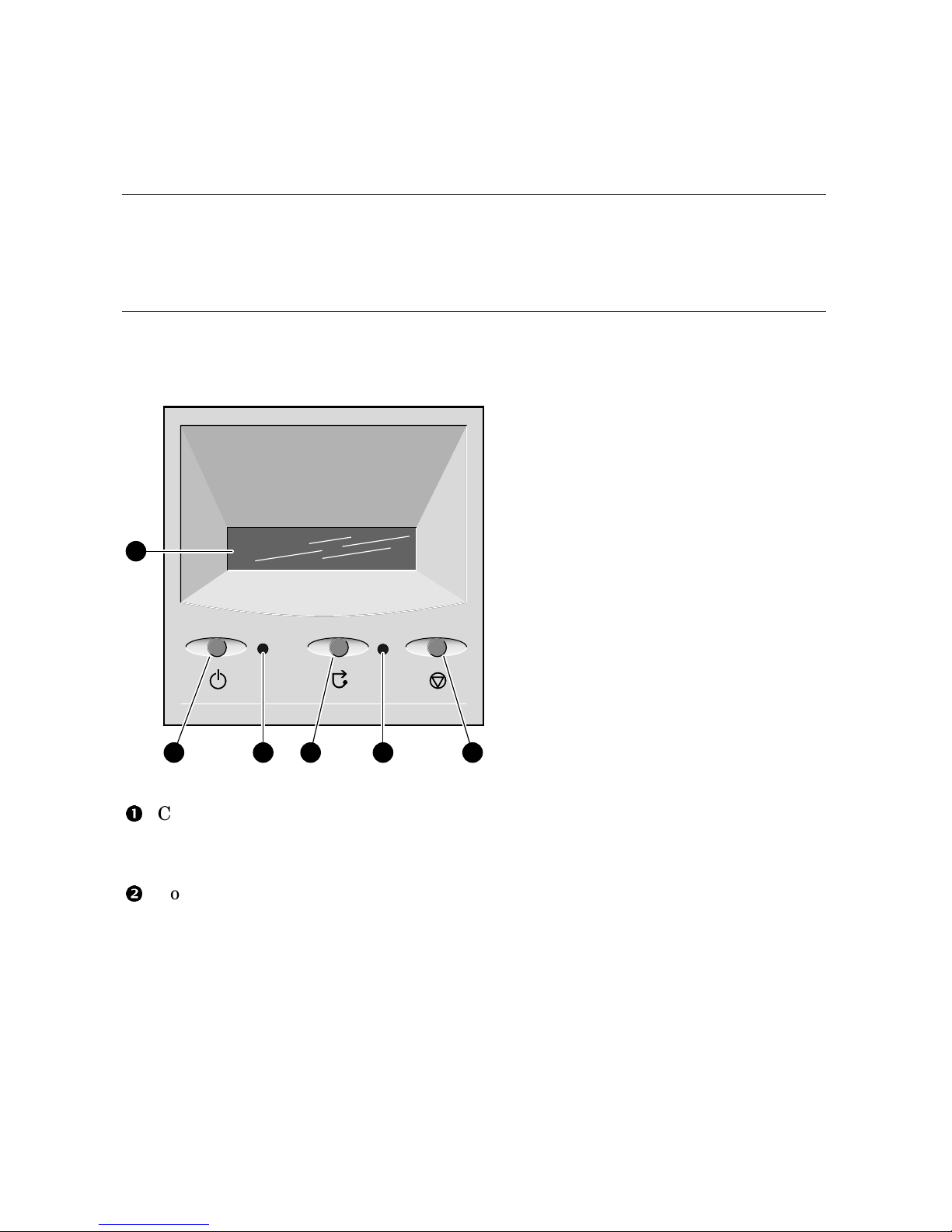
1.6 Operator Control Panel
The control panel provides system controls and status indicators. The
controls are the Power, Halt, and Reset buttons. A 16-character backlit alphanumeric display indicates system state. The panel has two
LEDs: a green Power OK indicator and an amber Halt indicator.
Figure 1–5 Operator Control Panel
PK0204
1
2 3 4 5 6
Control panel display. A one-line, 16-character alphanumeric display that
indicates system status during power-up and testing. During operation, the
control panel is back lit.
Power button. Powers the system on and off.
If a failure occurs that causes the system to shut down, pressing the power
button off and then on clears the shutdown condition and attempts to power
the system back on. Some conditions that prevent the system from powering on can be determined by entering the env command from the remote
management console (RMC). The RMC is powered separately from the rest
of the system and can operate as long as AC power is present. (See Chapter
6.)
Page 27

System Overview 1-11
Power LED (green). Lights when the power button is pressed.
Reset button. A momentary contact switch that restarts the system and
reinitializes the console firmware. Power-up messages are displayed, and
then the console prompt is displayed or the operating system boot messages
are displayed, depending on how the startup sequence has been defined.
Halt LED (amber). Lights when you press the Halt button.
Halt button. Halts the system and returns to the SRM console.
If the Halt button is latched when the system is reset or powered up, the
system halts in the SRM console. Systems that are configured to autoboot
cannot boot until the Halt button is unlatched.
Commands issued from the remote management console (RMC) can be used to
reset, halt, and power the system on or off. For information on RMC, see Chapter 6.
RMC Command Function
Power {off, on} Equivalent to pressing the Power button on the system. If
the power button is in the Off position, the RMC Power On
command has no effect.
Halt {in, out} Equivalent to pressing the Halt button on the control panel
to cause a halt (halt in) or releasing it from the latched posi-
tion to de-assert the halt (halt out).
Reset
Equivalent to pressing the Reset button on the control panel.
Page 28

1-12 ES45 Owner’s Guide
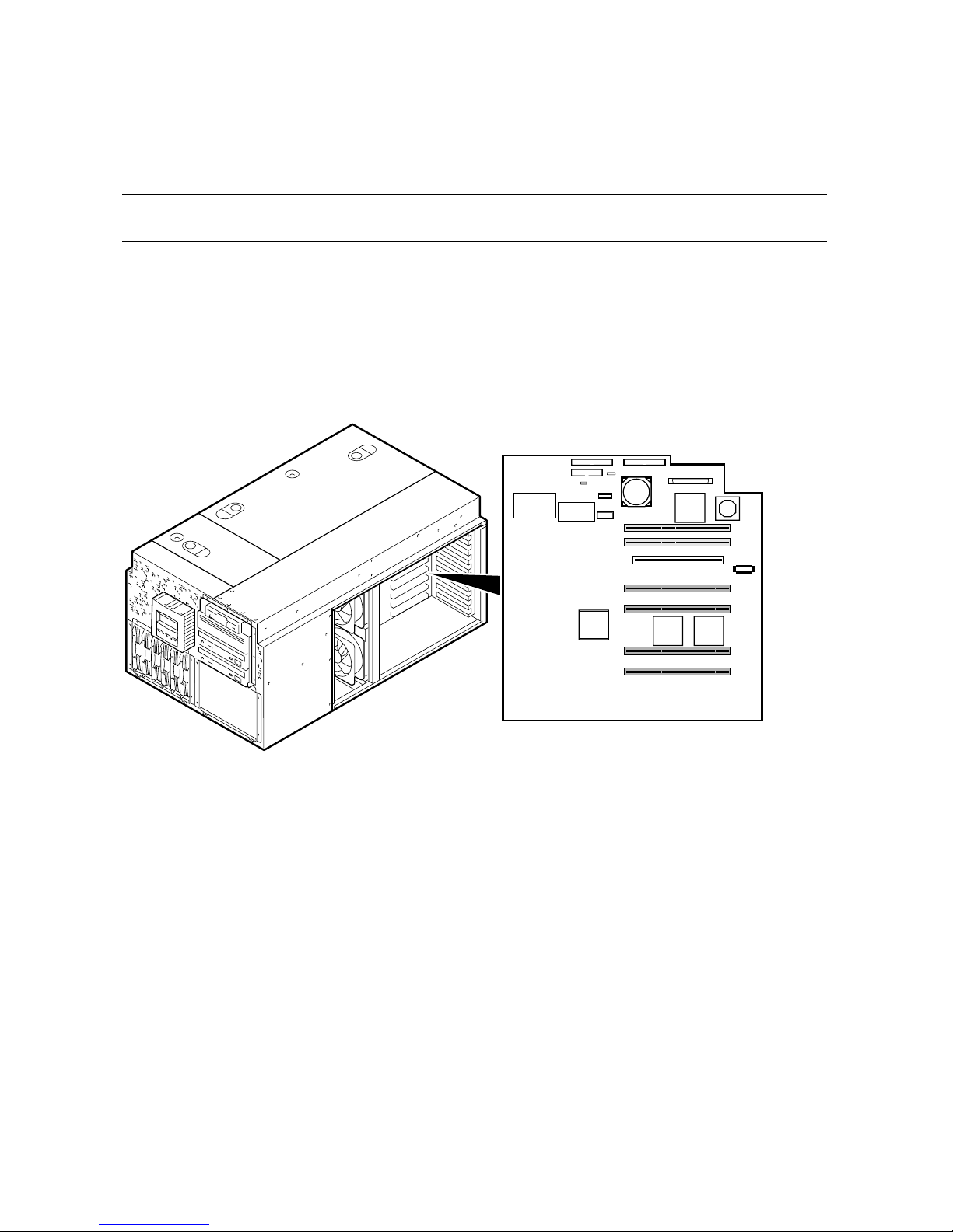
1.7 System Motherboard
The system motherboard is located on the floor of the system card cage
and has the majority of the logic for the system.
The system motherboard has connectors for the CPUs and memory motherboards (MMBs) and a connector to the I/O subsystem. Figure 1–6 shows the
location of these modules on the motherboard.
Figure 1–6 System Motherboard Block Diagram
MMB3
MMB2
MMB1
MMB0
J34
J33
J32
J31
CPU2
CPU0
CPU1
CPU3
J18
J17
J16
J15
Connector to PCI Backplane
Vterm
(VTerm_data)
Cterm
(VTerm_chk)
PK0323C
Page 29

System Overview 1-13
CPU Card
The system can have up to four CPU cards. The CPU cards are installed on the
system board. Each CPU card contains an EV68 microprocessor, a current implementation of the Alpha architecture.
The microprocessor is a superscalar CPU with out-of-order execution and speculative execution to maximize speed and performance. It contains four integer
execution units and dedicated execution units for floating-point add, multiply,
and divide. It has an instruction cache and a data cache on the chip. Each
cache is a 64 KB, two-way, set-associative, virtually addressed cache that has
64-byte blocks. The data cache is a physically tagged, write-back cache.
Each CPU card has an 8 MB B-cache (backup cache) and a power regulator.
See Chapter 4 for instructions on installing additional CPUs.
Memory Motherboards (MMBs)
Memory options are installed into memory motherboards (MMBs) located on the
system motherboard (see Figure 1–6). There are four MMBs. The MMBs have
either four or eight slots for installing DIMMs.
See Chapter 4 for memory configuration rules and installation instructions.
Page 30
1-14 ES45 Owner’s Guide
1.8 I/O Backplane
The ES45 server has three I/O versions: Models 1B, 2B, and 3B.
1.8.1 Model 1B
Model 1B has six PCI slots with four at 66 MHz, two at 33 MHz, and one AGP
4x slot.
Figure 1–7 Location of I/O Slots: Model 1B
MR0262A
123 4 5 6 7 8 910
Page 31

System Overview 1-15
There is no direct correspondence between the physical numbers of the slots on
the I/O backplane and the logical slot identification reported with the SRM console show config command (described in Chapter 2). Table 1–2 maps the
physical slot numbers to the SRM logical ID numbers.
See Chapter 4 for instructions on installing PCI options.
Table 1–2 How Physical I/O Slots Map to Logical Slots: Model 1B
Physical Slot SRM Logical ID (7-Slot PCI)
1
Hose 0 Slot ID 11
2
Hose 0 Slot ID 10
3
Hose 2 Slot ID 5
4
Hose 3 Slot ID 2
5
Hose 3 Slot ID 1
7
Hose 1 Slot ID 2
8
Hose 1 Slot ID 1
Page 32

1-16 ES45 Owner’s Guide
1.8.2 Model 2B
Model 2B has ten slots with six slots at 66 MHz and four slots at 33 MHz
(Model 2 uses the same configuration).
Figure 1–8 Location of I/O Slots: Model 2B (Pedestal/Rack View)
10-Slot
PCI
PK0226D
123 4 5 6 7 8 910
Page 33

System Overview 1-17
There is no direct correspondence between the physical numbers of the slots on
the I/O backplane and the logical slot identification reported with the SRM console show config command (described in Chapter 2). Table 1–3 maps the
physical slot numbers to the SRM logical ID numbers.
See Chapter 4 for instructions on installing PCI options.
Table 1–3 How Physical I/O Slots Map to Logical Slots: Model 2B
Physical Slot SRM Logical ID (10-Slot PCI)
1
Hose 2 Slot ID 1
2
Hose 2 Slot ID 2
3
Hose 0 Slot ID 11
4
Hose 3 Slot ID 2
5
Hose 3 Slot ID 1
6
Hose 0 Slot ID 10
7
Hose 1 Slot ID 2
8
Hose 1 Slot ID 1
9
Hose 0 Slot ID 9
10
Hose 0 Slot ID 8
Page 34

1-18 ES45 Owner’s Guide
1.8.3 Model 3B
The Model 3B has ten slots with eight at 33 MHz and two at 66 MHz.
Figure 1–9 Location of I/O Slots: Model 3B
MR0263
123 4 5 6 7 8 910
10-Slot
PCI
Page 35

System Overview 1-19
There is no direct correspondence between the physical numbers of the slots on
the I/O backplane and the logical slot identification reported with the SRM console show config command (described in Chapter 2). Table 1–4 maps the
physical slot numbers to the SRM logical ID numbers.
See Chapter 4 for instructions on installing PCI options.
Table 1–4 How Physical I/O Slots Map to Logical Slots: Model 3B
Physical Slot SRM Logical ID (10-Slot Legacy PCI)
1
Hose 2 Slot ID 1
2
Hose 2 Slot ID 2
3
Hose 0 Slot ID 11
4
Hose 3 Slot ID 2
5
Hose 3 Slot ID 1
6
Hose 0 Slot ID 10
7
Hose 1 Slot ID 2
8
Hose 1 Slot ID 1
9
Hose 0 Slot ID 9
10
Hose 0 Slot ID 8
Page 36

1-20 ES45 Owner’s Guide
1.9 Power Supplies
The power supplies provide power to components in the system chassis. The number of power supplies required depends on the system
configuration.
Figure 1–10 Power Supplies
00
11
22
Tow er
Pedestal/Rack
00111222
1
2
PK0207A
Page 37

System Overview 1-21
One to three power supplies provide power to components in the system chassis.
The system supports redundant power configurations to ensure continued system operation if a power supply fails (The Model 2 has a minimum configuration of two power supplies).
The power supplies select line voltage and frequency are automatically selected
for 200–240 V and 50 Hz or 60 Hz.
Power Supply LEDs
Each power supply has two green LEDs that indicate the state of power to the
system.
POK (Power OK)
Indicates that the power supply is functioning. The POK
LEDisonwhenthesystemisrunning. Whenthesystem power is on and a POK LED is off, that supply is not
contributing to powering the system.
+5 V Auxiliary
Indicates that AC power is flowing from the wall outlet.
As long as the power supply cord is plugged into the wall
outlet, the +5V Aux LED is always on, even when the
system power is off.
See Chapter 4 for instructions on installing additional power supplies.
Page 38

1-22 ES45 Owner’s Guide
1.10 Removable Media Storage
The system chassis houses a CD-ROM driveand a high-density 3.5inch floppy diskette drive
and supports two additional 5.25-inch
half-height devices or one additional full-height device.
See Chapter 4 for information on installing a removable media drive.
Figure 1–11 Removable Media Drive Area
PK0233
1
2
Page 39

System Overview 1-23
1.11 Storage Subsystem
The system chassis can house up to two universal storage disk cages.
The storage subsystem supports “hot pluggable" hard disk drives that
can be replaced while the storage backplane is powered and operating.
You can install up to six 1-inch universal hard drives in each storage disk cage.
See Chapter 4 for installation and swap procedures.
Figure 1–12 Storage Cages
MR0046A
Page 40

1-24 ES45 Owner’s Guide
1.12 System Access
Atthetimeofdelivery,thesystemkeysaretapedinsidethesmallfront
door that provides access to the operator control panel and removable
media devices.
Figure 1–13 System Keys
Tower
Pedestal
PK0224A
Page 41

System Overview 1-25
Both the tower and pedestal systems have a small front door through which
the control panel and removable media devices are accessible. At the time of
delivery, the system keys are taped inside this door.
The tower front door has a lock that lets you secure access to the disk drives
andtotherestofthesystem.
The pedestal has two front doors, both of which can be locked. The upper door
secures the disk drives and access to the rest of the system, and the lower door
secures the expanded storage.
NOTE: See Chapter 4 for warnings and procedures for accessing internal parts
of the system.
Page 42

1-26 ES45 Owner’s Guide
1.13 Console Terminal
The console terminal can be a serial (character cell) terminal connectedtotheCOM1orCOM2portoraVGAmonitorconnectedtoa
VGA adapter on PCI0. A VGA monitor requires a keyboard and mouse.
Figure 1–14 Console Terminal Connections
VT
Tower
Pedestal/Rack
PK0225B
VT
Page 43

Operation 2-1
Chapter 2
Operation
This chapter gives instructions for basic system operation. The following topics
are covered:
• Powering Up the System
• Power-Up Displays
• SRM Console
• Displaying the Hardware Configuration
• Setting SRM Environment Variables
• Setting Console Security
• Updating Firmware
Page 44

2-2 ES45 Owner's Guide
2.1 PoweringUptheSystem
To power up the system, press the power button. Testing begins, and
status shows on the console terminal screen and in the control panel
display.
Figure 2–1 Operator Control Panel
PK0204A
2
1
Power button
Control panel display
Page 45

Operation 2-3
2.2 Power-Up Displays
Power-up information is displayed on the operator control panel and
on the console terminal startup screen. Messages sent from the SROM
(serial read-only memory) program are displayed first, followed by
messages from the SRM console.
NOTE: The power-up text that is displayed on the screen depends on what kind
of terminal is connected as the console terminal: VT or VGA.
If the SRM console environment variable is set to serial,theentire
power-up display, consisting of the SROM and SRM power-up messages, is displayed on the VT terminal screen. If console is set to
graphics, no SROM messages are displayed, and the SRM messages
are delayed until VGA initialization has been completed.
• Section 2.2.1 shows the SROM power-up messages and corresponding op-
erator control panel (OCP) messages.
• Section 2.2.2 shows the messages that are displayed once the SROM has
transferred control to the SRM console.
• For a complete list of messages displayed on the OCP, see Chapter 7.
Page 46

2-4 ES45 Owner's Guide
2.2.1 SROM Power-Up Display
Example 2–1 Sample SROM Power-Up Display
SROM V2.15 CPU # 00 @ 1000 MHz PCI Test
SROM program starting
Reloading SROM
Power on
SROM V2.15 CPU # 00 @ 1000 MHz
System Bus Speed @ 0125 MHz
SROM program starting
PCI66 bus speed check
Reloading SROM
RelCPU
SROM V2.15 CPU # 00 @ 1000 MHz
System Bus Speed @ 0125 MHz
SROM program starting
PCI66 bus speed check
Starting secondary on CPU #1
Starting secondary on CPU #2
Starting secondary on CPU #3
Bcache data tests in progress
Bcache address test in progress
CPU parity and ECC detection in progress
BC Data
Bcache ECC data tests in progress
Bcache TAG lines tests in progress
Memory sizing in progress
Memory configuration in progress
Testing AAR3
Memory data test in progress
Memory address test in progress
Memory pattern test in progress
Testing AAR2
Memory data test in progress
Memory address test in progress
Memory pattern test in progress
Testing AAR1
Memory data test in progress
Memory address test in progress
Memory pattern test in progress
Testing AAR0
Memory data test in progress
Memory address test in progress
Memory pattern test in progress
Memory thrashing test in progress
Memory initialization
Size Mem
Loading console
Code execution complete (transfer control)
Load ROM
Jump to
Console
Page 47

Operation 2-5
When the system powers up, the SROM code is loaded into the I-cache (instruction cache) on the first available CPU, which becomes the primary CPU.
The order of precedence is CPU0, CPU1, and so on. The primary CPU attempts to access the PCI bus. If it cannot, either a hang or a failure occurs,
and this is the only message displayed.
The primary CPU interrogates the I2C EEROM on the system board and CPU
modules through shared RAM. The primary CPU determines the CPU and
system configuration to jump to.
The primary CPU next checks the SROM checksum to determine the validity
of the flash SROM sectors.
If flash SROM is invalid, the primary CPU reports the error and continues the
execution of the SROM code. Invalid flash SROM must be reprogrammed.
If flash SROM is good, the primary CPU programs appropriate registers with
the values from the flash data and selects itself as the target CPU to be
loaded.
The primary CPU (usually CPU0) initializes and tests the B-cache and memory, then loads the flash SROM code to the next CPU. That CPU then initializes the EV68 chip) and marks itself as the secondary CPU. Once the primary
CPU sees the secondary, it loads the flash SROM code to the next CPU until
all remaining CPUs are loaded.
The flash SROM performs B-cache tests. For example, the ECC data test verifies the detection logic for single- and double-bit errors.
The primary CPU initiates all memory tests. The memory is tested for address and data errors for the first 32 MB of memory in each array. It also initializes all the “sized” memory in the system.
If a memory failure occurs, an error is reported. An untested memory array is
assigned to address 0 and the failed memory array is de-assigned. The memory tests are rerun on the first 32 MB of memory in each of the remaining arrays. If all memory fails, the “No Memory Available” message is reported and
the system halts.
If all memory passes, the primary CPU loads the console and transfers control
to it.
Page 48

2-6 ES45 Owner's Guide
2.2.2 SRM Console Power-Up Display
At the completion of SROM power-up, the primary CPU transfers control to the SRM console program, described in Section 2.3. The console
program continues the system initialization. Failures are reported to
the console terminal through the power-up screen and a console event
log.
Example 2–2 SRM Power-Up Display
OpenVMS PALcode V1.88-28, Tru64 UNIX PALcode V1.83-24
starting console on CPU 0
initialized idle PCB
initializing semaphores
initializing heap
initial heap 240c0
memory low limit = 1e6000
heap = 240c0, 17fc0
initializing driver structures
initializing idle process PID
initializing file system
initializing timer data structures
lowering IPL
CPU 0 speed is 1000 MHz
create dead_eater
create poll
create timer
create powerup
access NVRAM
4096 MB of System Memory
Testing Memory
...
probe I/O subsystem
Hose0-PCIbusrunningat33Mhz
entering idle loop
probing hose 0, PCI
probing PCI-to-ISA bridge, bus 1
probing PCI-to-PCI bridge, bus 2
bus0,slot8--pka--NCR53C895
bus 0, slot 9 -- eia -- DE600-AA
bus2,slot0--pkb--NCR53C875
bus2,slot1--pkc--NCR53C875
bus 2, slot 2 -- ewa -- DE500-AA Network Controller
bus 0, slot 16 -- dqa -- Acer Labs M1543C IDE
bus 0, slot 16 -- dqb -- Acer Labs M1543C IDE
Hose1-PCIbusrunningat66Mhz
probing hose 1, PCI
bus 0, slot 2 -- vga -- 3Dlabs OXYGEN VX1
Hose2-AGPbus
Page 49

Operation 2-7
probing hose 2, PCI
Hose3-PCIbusrunningat33Mhz
probing hose 3, PCI
probing PCI-to-PCI bridge, bus 2
bus 2, slot 4 -- eib -- DE602-AA
bus 2, slot 5 -- eic -- DE602-AA
bus 2, slot 6 -- eid -- DE602-FA
bus 0, slot 2 -- fwa -- DEFPA
starting drivers
The primary CPU prints a message indicating that it is running the console.
Starting with this message, the power-up display is sent to any console terminal, regardless of the state of the console environment variable.
If console is set to graphics, the display from this point on is saved in a
memory buffer and displayed on the VGA monitor after the PCI buses are
sized and the VGA device is initialized.
The memory size is determined and memory is tested.
The I/O subsystem is probed and I/O devices are reported. I/O adapters are
configured.
Device drivers are started.
Continuedonnextpage
Page 50

2-8 ES45 Owner's Guide
Example 2–2 SRM Power-Up Display (Continued)
initializing keyboard
starting console on CPU 1
initialized idle PCB
initializing idle process PID
lowering IPL
CPU 1 speed is 1000 MHz
create powerup
entering idle loop
starting console on CPU 2
initialized idle PCB
initializing idle process PID
lowering IPL
CPU 2 speed is 1000 MHz
create powerup
starting console on CPU 3
initialized idle PCB
initializing idle process PID
lowering IPL
CPU 3 speed is 1000 MHz
create powerup
initializing GCT/FRU at 220000
initializing pka pkb pkc ewa fwa dqa dqb eia eia0: link up :
Negotiated 100Basx
eib eic eid
Memory Testing and Configuration Status
Array Size Base Address Intlv Mode
--------- ---------- ---------------- ---------0 4096Mb 0000000000000000 2-Way
1 1024Mb 0000000200000000 2-Way
2 4096Mb 0000000100000000 2-Way
3 1024Mb 0000000240000000 2-Way
10240MBofSystemMemory
AlphaServer ES45 Console V5.9-9, built on June 2001 at
17:09:49
Page 51

Operation 2-9
The console is started on the secondary CPUs. The example shows a fourprocessor system.
Various diagnostics are performed.
The console terminal displays the SRM console banner and the prompt,
Pnn>>>. The number n indicates the primary processor. In a multiprocessor system, the prompt could be P00>>>, P01>>>, P02>>>, or P03>>>.
From the SRM prompt, you can boot the operating system.
Page 52

2-10 ES45 Owner's Guide
2.3 SRM Console
The SRM console is the command-line interface that allows you to set
up and boot the operating system, display the system configuration, set
environment variables, and perform basic system troubleshooting.
SRM firmware is located in a flash ROM (read-only memory) on the system board. The SRM console firmware is described in detail in
Chapter 5, Firmware.
The following sections cover functions you can perform from SRM.
Example 2–3 SRM Console Example
P00>>> set bootdef_dev dkb0,dka0
In this example, the operator enters the SRM set command and specifies the
devices from which to boot the operating system. At power-up the system will
try to boot from SCSI device dkb0 and if unsuccessful, will boot from dka0.
Page 53

Operation 2-11
2.3.1 Selecting the Display Device
The SRM console environment variable determines to which display
device (VT-type terminal or VGA monitor) the console display is sent.
The console terminal that displays the SRM user interface can be either a serial
terminal (VT320 or higher, or equivalent) or a VGA monitor.
The SRM console environment variable determines the display device.
• If you use a VT-type device as the console terminal, set the console envi-
ronment variable to serial. The VT device can be connected to the MMJ
port or to the dedicated modem port.
• If you use a VGA monitor as the console terminal, set the console environ-
ment variable to graphics.
You can verify the display device with the SRM show console command and
change the display device with the SRM set console command. If you change
the display device setting, you must reset the system (with the Reset button or
the init command) to put the new setting into effect.
In the following example, the operator displays the current console device (a
graphics device) and then resets it to a serial device. After the system initializes, output will be displayed on the serial terminal.
P00>>> show console
console graphics
P00>>> set console serial
P00>>> init
.
.
.
Page 54

2-12 ES45 Owner's Guide
2.3.2 Setting a Control Panel Message
You can create a customized message to be displayed on the operator
control panel after startup self-tests and diagnostics have been completed.
When the operating system is running, the control panel displays the console
revision. It is useful to create a customized message if you have a number of
systems and you want to identify each system by a node name.
You can use the SRM set ocp_text command to change this message. The
message can be up to 16 characters and must be entered in quotation marks, as
shown in Example 2–4.
Example 2–4 Set Ocp_Text Command
P00>>> set ocp_text “Node Alpha1”
Page 55

Operation 2-13
2.4 Displaying the Hardware Configuration
View the system hardware configuration from the SRM console. It is
useful to view the hardware configuration to ensure that the system
recognizes all devices, memory configuration, and network connections.
Use the following SRM console commands to view the system configuration.
show boot*
Displays the boot environment variables.
show config Displays the logical configuration of interconnects and buses
on the system and the devices found on them.
show device
Displays the bootable devices and controllers in the system.
show fru Displays the physical configuration of FRUs (field-replaceable
units). See Chapter 7 for information on this command.
show memory
Displays configuration of main memory.
Page 56

2-14 ES45 Owner's Guide
2.4.1 Displaying Boot Environment Variables
Use the show boot* command to list the boot environment variables.
Use the set command with a variable to set up the boot environment.
See Chapter 3 for more information on setting boot environment variables.
Example 2–5 Show Boot*
P00>>> show boot*
boot_dev dka0.0.0.1.1
boot_file
boot_osflags a
boot_reset OFF
bootdef_dev dka0.0.0.1.1
booted_dev
booted_file
booted_osflags
Page 57

Operation 2-15
boot_dev Device or device list from which booting is to be at-
tempted, here SCSI device dka0.
boot_file The default file name used for the primary bootstrap
when no file name is specified by the boot command.
boot_osflags
Boot flags, here the Tru64 UNIX “a” (autoboot) flag.
boot_reset
Action taken in response to an error halt or boot command. OFF, the default, indicates a warm boot (no full
reset is performed).
bootdef_dev Device or device list from which booting is to be attempted
when no path is specified on the command line. Here,
SCSI device dka0.
booted_dev
The device from which booting occurred.
booted_file The file name used for the primary bootstrap during the
last boot.
booted_osflags
Additional parameters, if any, specified by the last boot
command that are to be interpreted by system software.
Page 58

2-16 ES45 Owner's Guide
2.4.2 Displaying the Logical Hardware Configuration
Use the show config command to display the logical configuration. To
display the physical configuration, issue the show fru command.
Example 2–6 Show Config
P00>>> show config
Compaq Computer Corporation
Compaq AlphaServer ES45 Model 2B
Firmware
SRM Console: V5.9-9
PALcode: OpenVMS PALcode V1.91-33, Tru64 UNIX PALcode V1.87-27
Serial ROM: V2.18-F
RMC ROM: V1.8
RMC Flash ROM: V1.7
Processors
CPU 0 Alpha EV68CB pass 2.4 1000 MHz 8MB Bcache
CPU 1 Alpha EV68CB pass 2.4 1000 MHz 8MB Bcache
CPU 2 Alpha EV68CB pass 2.4 1000 MHz 8MB Bcache
CPU 3 Alpha EV68CB pass 2.4 1000 MHz 8MB Bcache
Core Logic
Cchip Rev 17
Dchip Rev 17
PPchip 0 Rev 17
PPchip 1 Rev 17
TIG Rev 2.6
Memory
Array Size Base Address Intlv Mode
--------- ---------- ---------------- ----------
0 4096Mb 0000000000000000 2-Way
1 1024Mb 0000000200000000 2-Way
2 4096Mb 0000000100000000 2-Way
3 1024Mb 0000000240000000 2-Way
Total Good Memory = 10240 MBytes
Page 59

Operation 2-17
Firmware. Version numbers of the SRM console, PALcode, serial ROM,
RMC ROM, and RMC flash ROM
Processors. Processors present, processor version and clock speed, and
amount of backup cache
Core logic. Version numbers of the chips that form the interconnect on
the system board
Memory. Memory arrays and memory size
Continuedonnextpage
Page 60

2-18 ES45 Owner's Guide
Example 2–6 Show Config (Continued)
Slot Option Hose 0, Bus 0, PCI − 33 MHz
7 Acer Labs M1543C Bridge to Bus 1, ISA
8 ELSA GLoria Synergy vga0.0.0.8.0
9 DECchip 21152-AA Bridge to Bus 2, PCI
10 DECchip 21041-AA ewe0.0.0.10.0 00-00-F8-1F-AE-0A
11 DE500-AA Network Con ewf0.0.0.11.0 00-00-F8-1B-0B-24
12 Yukon PCI Hot-Plug C
16 Acer Labs M1543C IDE dqa.0.0.16.0
dqb.0.1.16.0
dqa0.0.0.16.0 TOSHIBA CD-ROM XM-
6302B
Option Hose 0, Bus 1, ISA
Floppy dva0.0.0.1000.0
Slot Option Hose 0, Bus 2, PCI − 33 MHz
0 DE500-BA Network Con ewa0.0.0.2000.0 00-06-2B-00-E7-82
1 DE500-BA Network Con ewb0.0.0.2001.0 00-06-2B-00-E7-83
2 DE500-BA Network Con ewc0.0.0.2002.0 00-06-2B-00-E7-84
3 DE500-BA Network Con ewd0.0.0.2003.0 00-06-2B-00-E7-85
Slot Option Hose 1, Bus 0, PCI − 66 MHz
1/0 Adaptec AIC-7899 pka0.7.0.1.1 SCSI Bus ID 7
dka0.0.0.1.1 COMPAQ BD018122C9
1/1 Adaptec AIC-7899 pkb0.7.0.101.1 SCSI Bus ID 7
6 Yukon PCI Hot-Plug C
Slot Option Hose 2, Bus 0, PCI − 66 MHz
1 DEGPA-SA
2 DEGPA-SA
Slot Option Hose 3, Bus 0, PCI − 66 MHz
1/0 Adaptec AIC-7899 pkc0.7.0.1.3 SCSI Bus ID 7
1/1 Adaptec AIC-7899 pkd0.7.0.101.3 SCSI Bus ID 7
6 Yukon PCI Hot-Plug C
P00>>
This part of the command output shows the PCI cards on a system that has
a 10-slot I/O backplane.
The “Slot” column lists the slots (logical IDs) seen by the system. Logical
IDs identify both installed PCI cards and onboard chips. In this example,
the onboard chips include the Yukon PCI hot-plug controller and the Acer
Labs M1543C IDE.
The logical IDs do not correspond directly to the physical slots into which
thedevicesareinstalled. SeeTable2–2forthecorrespondencebetween
logical IDs and physical slots.
Page 61

Operation 2-19
NOTE: The naming of devices (for example,dqa.0.0.15.0) follows the con-
ventions given in Table 2–4.
The slots in Example 2–6 are from the Model 2B ten-slot backplane and
are explained below. An asterisk (*) indicates slots that contain a PCI
card.
Hose 0, Bus 0, PCI
Slot 7 Onboard Acer chip. Provides bridge to Bus 1, ISA
Slot 8* VGA card
Slot 9* Bridge chip to Bus 2, PCI
Slot 10* Ethernet card
Slot 11* Ethernet card
Slot 12 Onboard PCI hot-plug controller
Hose 0, Bus 1, ISA
The floppy drive. It is the only device that comes from the bridge.
Hose 0, Bus 2, PCI
Slots 0–3 Onboard controllers.
Hose 1, Bus 0, PCI
Slot 1/0, 1/1* Two-channel SCSI card
(Slot 2) Not shown because no card installed.
Slot 6 Onboard PCI hot-plug controller
Hose 2, Bus 0, PCI
Slot 1* Gigabit Ethernet card
Slot 2* Gigabit Ethernet card
Hose 3, Bus 0, PCI
Slot 1/0, 1/1* Two-channel SCSI card
(Slot 2) Not shown because no card installed.
Page 62

2-20 ES45 Owner's Guide
Table 2–1 Physical I/O Slots Map to Logical Slots: Model 1B
Physical Slot SRM Logical ID (7-Slot)
1
Hose 0 Slot ID 11
2
Hose 0 Slot ID 10
3
Hose 2 Slot ID 5
4
Hose 3 Slot ID 2
5
Hose 3 Slot ID 1
7
Hose 1 Slot ID 2
8
Hose 1 Slot ID 1
Table 2–2 Physical I/O Slots Map to Logical Slots: Model 2B
Physical Slot SRM Logical ID
1
Hose 2 Slot ID 1
2
Hose 2 Slot ID 2
3
Hose 0 Slot ID 11
4
Hose 3 Slot ID 2
5
Hose 3 Slot ID 1
6
Hose 0 Slot ID 10
7
Hose 1 Slot ID 2
8
Hose 1 Slot ID 1
9
Hose 0 Slot ID 9
10
Hose 0 Slot ID 8
Page 63

Operation 2-21
Table 2–3 Physical I/O Slots Map to Logical Slots: Model 3B
Physical Slot SRM Logical ID (10-Slot Legacy PCI)
1
Hose 2 Slot ID 1
2
Hose 2 Slot ID 2
3
Hose 0 Slot ID 11
4
Hose 3 Slot ID 2
5
Hose 3 Slot ID 1
6
Hose 0 Slot ID 10
7
Hose 1 Slot ID 2
8
Hose 1 Slot ID 1
9
Hose 0 Slot ID 9
10
Hose 0 Slot ID 8
Page 64

2-22 ES45 Owner's Guide
2.4.3 Displaying the Bootable Devices
Use the show device command to display the devices from which the
operating system can be booted.
Example 2–7 Show Device
P00>>> show device
dka0.0.0.1.1 DKA0 RZ2DD-LS 0306
dka100.1.0.1.1 DKA100 RZ2DD-LS 0306
dka200.2.0.1.1 DKA200 RZ1CB-CS 0844
dkb0.0.0.3.1 DKB0 RZ25 0900
dqa0.0.0.15.0 DQA0 TOSHIBA CD-ROM XM-6302B 1012
dva0.0.0.1000.0 DVA0
ewa0.0.0.4.1 EWA0 00-00-F8-09-90-FF
ewb0.0.0.2002.1 EWB0 00-06-2B-00-25-5B
pka0.7.0.1.1 PKA0 SCSI Bus ID 7
pkb0.7.0.3.1 PKB0 SCSI Bus ID 7
pkc0.7.0.2000.1 PKC0 SCSI Bus ID 7
pkd0.7.0.2001.1 PKD0 SCSI Bus ID 7
Page 65

Operation 2-23
Table 2–4 Device Naming Conventions
Category Description
The device, dqa0 is used as an example in the following device category and description.
dq
Driver ID Two-letter designator of port or class driver
dk SCSI drive or CD ew Ethernet port
dq IDE CD-ROM fw FDDI device
dr RAID set device mk SCSI tape
du DSSI disk mu DSSI tape
dv Diskette drive pk SCSI port
ei Ethernet port pu DSSI port
pz KZPCC-CE RAID
controller
a
Storage adapter ID One-letter designator of storage adapter
(a, b, c…).
0
Device unit number Unique number (MSCP unit number). SCSI unit numbers
are forced to 100 X node ID.
0
Bus node number Bus node ID.
0
Channel number Used for multi-channel devices.
15
Logical slot number Corresponds to PCI slot number, as shown in Table 2–2.
0
Hose number
• 0PCI0
• 1PCI1
• 2PCI2
• 3PCI3
Page 66

2-24 ES45 Owner's Guide
2.4.4 Viewing the Memory Configuration
Use the show memory command to view the configuration of main
memory.
Example 2–8 Show Memory
P00>>> show memory
Array Size Base Address Intlv Mode
--------- ---------- ---------------- ---------0 4096Mb 0000000000000000 2-Way
1 1024Mb 0000000200000000 2-Way
2 4096Mb 0000000100000000 2-Way
3 1024Mb 0000000240000000 2-Way
10240MBofSystemMemory
The show memory display corresponds to the memory array configuration described in Chapter 4. The display does not indicate the number of DIMMs or
the DIMM size. Thus, in Example 2–8, Array 3 could consist of two sets of 128
MB DIMMs (eight DIMMs) or one set of 256 MB DIMMs (four DIMMs). Either
combination provides 1024 MB of memory.
The output of the show memory command also provides the memory interleaving status of the system.
Use the show fru command to display the DIMMs in the system and their location. See Chapter 7.
Page 67

Operation 2-25
2.5 Setting SRM Environment Variables
You may need to set several SRM console environment variables and
built-in utilities to configure the system.
Set environment variables at the P00>>> prompt.
• To check the setting for a specific environment variable, enter the show
envar command, where the name of the environment variable is substituted for envar. To see a list of the environment variables, enter the
show* command.
• To reset an environment variable, use the set envar command, where the
name of the environment variable is substituted for envar.
The environment variables used to set up the boot environment are described in
Chapter 3. Chapter 5 covers other environment variables you are likely to use.
Page 68

2-26 ES45 Owner's Guide
2.6 Setting Console Security
You can set the SRM console to secure mode to prevent unauthorized
persons from modifying the system parameters or otherwise tampering
with the system from the console.
When the SRM is set to secure mode, you can use only two console commands:
• The boot command, to boot the operating system.
• The continue command, to resume running the operating system if you
have inadvertently halted the system.
The boot command cannot take command-line parameters when the console is
in secure mode. The console boots the operating system using the environment
variables stored in NVRAM (boot_file, bootdef_dev, boot_flags).
The console security commands are as follows:
set password
set secure
These commands put the console into secure mode.
clear password
Exits secure mode.
login Turns off console security for the current session. Once you
enter the login command in secure mode, you can enter any
SRM command as usual. However, the system automatically returns to secure mode when you enter the boot or
continue command or when you reset the system.
NOTE: The security features work only if access to the system hardware is de-
nied to unauthorized persons. Be sure the system is available only to
authorized persons.
Page 69

Operation 2-27
2.6.1 Setting the Console Password
Set the console password with the set password command. A password
is required for operating the system in secure mode.
Example 2–9 Set Password
P00>>> set password
Please enter the password:
Please enter the password again:
P00>>>
P00>>> set password
Please enter the password:
Please enter the password again:
Now enter the old password:
P00>>>
P00>>> set password
Please enter the password:
Password length must be between 15 and 30 characters
P00>>>
Page 70

2-28 ES45 Owner's Guide
The set password command sets the console password for the first time or
changes an existing password. It is necessary to set the password only if the
system is going to operate in secure mode.
The syntax is:
set password
Setting a password. If a password has not been set and the set password
command is issued, the console prompts for a password and verification.
The password and verification are not echoed.
Changing a password. If a password has been set and the set password
command is issued, the console prompts for the new password and verification, then prompts for the old password. The password is not changed if the
validation password entered does not match the existing password stored in
NVRAM.
The password length must be between 15 and 30 alphanumeric characters.
Any characters entered after the 30th character are not stored.
Page 71

Operation 2-29
2.6.2 Setting the Console to Secure Mode
To set the console to secure mode, first set the password. Then enter
the set secure command. The system immediately enters secure mode.
Example 2–10 Set Secure
P00>>> set secure
Console is secure. Please login.
P00>>> b dkb0
Console is secure - parameters are not allowed.
P00>>> login
Please enter the password:
P00>>> b dkb0
(boot dkb0.0.0.3.1)
.
.
.
The set secure command enables secure mode. If no password has been set,
you are prompted to set the password. Once you set a password and enter the
set secure command, secure mode is in effect immediately and only the con-
tinue, boot (using the stored parameters), and login commands can be per-
formed.
The syntax is:
set secure
The console is put into secure mode, and then the operator attempts to boot
the operating system with command-line parameters. A message is displayed indicating that boot parameters are not allowed when the system is
in secure mode.
The login command is entered to turn off security features for the current
console session. After successfully logging in, the operator enters a boot
command with command-line parameters.
Page 72

2-30 ES45 Owner's Guide
2.6.3 Turning Off Security During a Console Session
The login command turns off the security features, enabling access to
all SRM console commands during the current console session. The
system automatically returns to secure mode as soon as the boot or
continue command is entered or when the system is reset.
Example 2–11 Login
P00>>> login
Secure not set. Please set the password.
P00>>> set password
Please enter the password:
Please enter the password again:
P00>>> login
Please enter the password.
P00>>> show boot*
The login command is entered, but the system is not in secure mode. A
password must be set.
A password is set.
The login command is entered. After the password is entered, console security is turned off for the current session and the operator can enter commands.
Page 73

Operation 2-31
When you enter the login command, you are prompted for the current system
password. If a password has not been set, a message is displayed indicating that
there is no password in NVRAM. If a password has been set, this prompt is displayed:
Please enter the password:
If the password entered matches the password in NVRAM, when the prompt is
redisplayedtheconsoleisnolongerinsecuremodeandallconsolecommands
can be performed during the current console session.
If You Forget the Password
If you forget the current password, use the login command in conjunction with
the control panel Halt button to clear the password, as follows:
1. Enter the login command:
P00>>> login
2. When prompted for the password, press the Halt button to the latched posi-
tion and then press the Return (or Enter) key.
3. Press the Halt button to release the halt. The password is now cleared and
the console cannot be put into secure mode unless you set a new password.
Page 74

2-32 ES45 Owner's Guide
2.6.4 Returning to User Mode
The clear password command clears the password environment variable, setting it to zero. Once the password is cleared, you are returned
to user mode.
Example 2–12 Clear Password
P00>>> clear password
Please enter the password:
Console is secure
P00>>> clear password
Please enter the password:
Password successfully cleared.
P00>>>
The wrong password is entered. The system remains in secure mode.
The password is successfully cleared.
The clear password command is used to exit secure mode and return to user
mode. To use clear password, you must know the current password. Once
you clear the password, the console is no longer secure.
To clear the password without knowing the current password, you must use the
login command in conjunction with the Halt button, as described in Section
2.6.3.
Page 75

Operation 2-33
2.7 Updating Firmware
Typically, you update system firmware whenever the operating system
is updated. You might also need to update firmware if you add I/O device controllers and adapters, if enhancements are made to the firmware, or if the serial ROM or RMC firmware become corrupted.
Sources of Firmware Updates
The system firmware resides in the flash ROM located on the system board.
The Alpha Systems Firmware Update Kit comes on a CD-ROM, which is updated quarterly. You can also obtain Alpha firmware updates from the Internet.
Quarterly Update Service
TheAlphaSystemsFirmwareUpdateKitCD-ROMisavailablebysubscription
from Compaq.
Alpha Firmware Internet Access
You can also obtain Alpha firmware update files from the Internet:
http://ftp.digital.com/pub/DEC/Alpha/firmware/
If you do not have a Web browser, you can access files using anonymous ftp:
$ ftp ftp.digital.com
Name (ftp.digital.com:mcdowell): anonymous
331 Guest login ok, send ident as password.
Password:
230 Guest login ok, access restrictions apply.
Remote system type is UNIX.
Using binary mode to transfer files.
ftp> cd /pub/DEC/Alpha/firmware
ftp> ls
...
ftp> cd v5.0
ftp> ls
...
ftp> cd es45 (if that's what the directory will be called)
ftp> get README
The README file explains how to download firmware updates.
Page 76

2-34 ES45 Owner's Guide
2.7.1 Firmware Update Utility
The system firmware is updated from a Loadable Firmware Update
Utility (LFU). When you boot the medium containing the update image, the LFU banner and command descriptions are displayed. Enter
commands at the UPD> prompt.
Before updating the firmware, enter the list command to list the current revision of the firmware. Enter the update command to update the firmware
automatically.
Example 2–13 Update Utility Display
Checking dqa0.0.0.16.0 for the option firmware files. . .
Checking dva0.0.0.1000.0 for the option firmware files. . .
Option firmware files were not found on CD or floppy.
If you want to load the options firmware,
please enter the device on which the files are located(ewa0),
or just hit <return> to proceed with a standard console update:
***** Loadable Firmware Update Utility *****
-------------------------------------------------------------Function Description
--------------------------------------------------------------
Display Displays the system's configuration table.
Exit Done exit LFU (reset).
List Lists the device, revision, firmware name, and
update revision.
Update Replaces current firmware with loadable data image.
Verify Compares loadable and hardware images.
? or Help Scrolls this function table.
--------------------------------------------------------------
UPD> list
Page 77

Operation 2-35
Device Current Revision Filename Update Revision
SRM V5.9-8 srm_fw V5.9-9
srom V2.17-F srom_fw V2.18-F
UPD> u
Confirm update on:
SRM
srom
[Y/(N)]y
WARNING: updates may take several minutes to complete for each device.
DO NOT ABORT!
SRM Updating to V5.9-9... Verifying V5.9-9... PASSED.
srom Updating to V2.18-F... Verifying V2.18-F...PASSED.
UPD>
Page 78

2-36 ES45 Owner's Guide
2.7.2 Manual Updates
If RMC firmware or serial ROM (SROM) become corrupted, you can
perform a manual update.
1. Boot the update medium.
2. At the UPD> prompt, enter the exit command and answer y at the prompt:
UPD> exit
Do you want to do a manual update [y/(n)] y
AlphaServer ES45 Console V5.9-9, built on Jan 9,2001 at
05:02:30
3. To update RMC firmware, enter update rmc. To update the serial ROM
(SROM), enter update srom. For example:
UPD> update srom
The remainder of the display is similar to that shown in Example 2–13.
Page 79

Operation 2-37
2.7.3 Updating from the CD-ROM
You can update the system firmware from CD-ROM.
1. At the SRM console prompt, enter the show device command to determine
the drive name of the CD-ROM drive.
2. Load the Alpha Systems Firmware Update CD into the drive.
3. Boot the system from the CD, using the drive name determined in step 1
(for example, dqa0).
P00>>> boot dqa0
4. Enter the update command at the UPD> prompt.
5. When the update is complete, exit from the Firmware Update Utility.
UPD> exit
Page 80

2-38 ES45 Owner's Guide
2.7.4 Updating from an OpenVMS System Disk
You can update the firmware from an OpenVMS system disk.
1. Download the firmware update image from the Firmware Updates Web site.
2. Rename the downloaded file to fwupdate.exe.
3. Enter the following commands on the OpenVMS Alpha system:
$ set file/attr=(rfm:fix,lrl:512,mrs:512,rat:none) fwupdate.exe
$ copy/contiguous fwupdate.exe "system_disk":[sys0.sysexe]
NOTE: Insert the name of your system disk in place of "system_disk,” for
example, dka100:.
4. Shut down the operating system to get to the SRM console prompt.
5. Boot the update utility from the SRM console as follows:
P00>>> boot dka100 -flags 0,a0
NOTE: Replace dka100 with the name of the system disk, if different.
6. After some messages are displayed, you will be prompted for the bootfile.
Enter the directory and file name as follows :
Bootfile: [sys0.sysexe]fwupdate.exe
7. Enter the update command at the UPD> prompt.
Page 81

Operation 2-39
2.7.5 Updating from the Network
You can update firmware from the network using the MOP protocol for
OpenVMS or the BOOTP protocol for Tru64 UNIX.
Updating Firmware Using BOOTP
1. Download the firmware update image from the Firmware Updates Web site.
2. Copy the downloaded file to a UNIX based network server for BOOTP boot-
ing on the system. For details on configuring the BOOTP server, refer to
Tru64 UNIX documentation or the system's Firmware Release Notes document.
3. Enter the update command at the UPD> prompt.
Updating Firmware Using MOP
1. Download the firmware update image from the Firmware Updates Web site.
2. Copy the downloaded file to an OpenVMS based network server for MOP
booting on the system. For details on configuring the MOP server, refer to
OpenVMS documentation or the system's Firmware Release Notes document.
3. To ensure that the downloaded file is in a proper VMS fixed record format,
enter the following command before using the file for MOP booting:
$ set file/attr=(rfm:fix,lrl:512,mrs:512,rat:none) “fwupdate.sys”
NOTE: Replace “fwupdate.sys” withthenameofthefirmwareimageyou
downloaded.
4. Boot the update file. For example:
P00>>> boot -file fwupdate eia0
5. Enter the update command at the UPD> prompt.
Page 82

Page 83

Booting and Installing an Operating System 3-1
Chapter 3
Booting and Installing
an Operating System
This chapter gives instructions for booting the Tru64 UNIX, OpenVMS,or
Linux operating systems and for starting an operating system installation. Refer to your operating system documentation for complete instructions on booting
or starting an installation.
The following topics are covered:
• Setting Boot Options
• Booting Tru64 UNIX
• Starting a Tru64 UNIX Installation
• Booting Linux
• Booting OpenVMS
• Starting an OpenVMS Installation
NOTE: Your system may have been delivered to you with factory-installed soft-
ware (FIS); that is, with a version of the operating system already installed. If so, refer to the FIS documentation included with your system
to boot your operating system for the first time. Linux-ready systems do
not come with factory-installed software.
Page 84

3-2 ES45 Owner's Guide
3.1 Setting Boot Options
You can set a default boot device, boot flags, and network boot protocols by using the SRM set command with environment variables. Once
these environment variables are set, the boot command defaults to the
stored values. You can override the stored values for the current boot
session by entering parameters on the boot command line. For more
information on setting boot options, see Chapter 5.
The SRM boot-related environment variables are listed below and described in
the following sections:
auto_action Determines the default action the system takes when the
system is power cycled, reset, or experiences a failure.
bootdef_dev Device or device list from which booting is to be attempted
when no path is specified on the command line.
boot_file Specifies a default file name to be used for booting when
no file name is specified by the boot command.
boot_osflags Defines parameters (boot flags) used by the operating sys-
tem to determine some aspects of a system bootstrap.
ei*0_inet_init or
ew*0_inet_init
Determines whether the interface's internal Internet database is initialized from nvram or from a network server
(through the bootp protocol). Set this environment variableifyouarebootingTru64 UNIX from a RIS server.
ei*0_protocols or
ew*0_protocols
Defines a default network boot protocol (bootp or mop).
Page 85

Booting and Installing an Operating System 3-3
3.1.1 auto_action
The SRM auto_action environment variable determines the default action the system takes when the system is power cycled, reset, or experiences a failure.
Systems can boot automatically (if set to autoboot) from the default boot device
under the following conditions:
• When you first turn on system power
• When you power cycle or reset the system
• When system power comes on after a power failure
• After a bugcheck (OpenVMS)orpanic(Tru64 UNIX or Linux)
The factory setting for auto_action is halt.Thehalt setting causes the system
to stop in the SRM console. You must then boot the operating system manually.
For maximum system availability, auto_action can be set to boot or restart.
• With the boot setting, the operating system boots automatically after the
SRM init command is issued or the Reset button is pressed.
• With the restart setting, the operating system boots automatically after the
SRM init command is issued or the Reset button is pressed, and it also reboots after an operating system crash.
Example
To set the default action to boot, enter the following SRM commands:
P00>>> set auto_action boot
P00>>> init
Page 86

3-4 ES45 Owner's Guide
3.1.2 bootdef_dev
The bootdef_dev environment variable specifies one or more devices
from which to boot the operating system. When more than one device is
specified, the system searches in the order listed and boots from the
first device.
Enter the show bootdef_dev command to display the current default boot de-
vice. Enter the show device command for a list of all devices in the system.
The syntax is:
set bootdef_dev boot_device
boot_device The name of the device on which the system software has been
loaded. To specify more than one device, separate the names with
commas.
Example
In this example, two boot devices are specified. The system will try booting
from dkb0 and, if unsuccessful, will boot from dka0.
P00>>> set bootdef_dev dkb0, dka0
NOTE: When you set the bootdef_dev environment variable, it is recom-
mended that you set the operating system boot parameters as well, using the set boot_osflags command.
Page 87

Booting and Installing an Operating System 3-5
3.1.3 boot_file
The boot_file environment variable specifies the default file name to be
used for booting when no file name is specified by the boot command.
The syntax is:
set boot_file filename
Example
P00>>> set boot_file “”
NOTE: This command clears the boot file setting and sets the string to empty.
Page 88

3-6 ES45 Owner's Guide
3.1.4 boot_osflags
The boot_osflags environment variable sets the default boot flags and,
for OpenVMS,arootnumber.
Boot flags contain information used by the operating system to determine some
aspects of a system bootstrap. Under normal circumstances, you can use the
default boot flag settings.
To change the boot flags for the current boot only, use the flags_value argument
with the boot command.
The syntax is:
set boot_osflags flags_value
The flags_value argument is specific to the operating system.
Tru64 UNIX Systems
Tru64 UNIX systems take a single ASCII character as the flags_value argument.
a
Load operating system software from the specified boot device (autoboot). Boot to multiuser mode.
i
Prompt for the name of a file to load and other options (boot interactively). Boot to single-user mode.
s
Stop in single-user mode. Boots /vmunix to single-user mode and stops
at the # (root) prompt.
D Full dump; implies “s” as well. By default, if UNIX crashes, it com-
pletes a partial memory dump. Specifying “D” forces a full dump at
system crash.
Example
The following setting will autoboot Tru64 UNIX to multiuser mode when you
enter the boot command.
P00>>> set boot_osflags a
Page 89

Booting and Installing an Operating System 3-7
Linux Systems
If aboot.conf contains (0: 1/vmlinux.gz ro root=/dev/sda2), the system can be
booted by one of the following methods:
1.
set boot_file
set boot_osflags 0
boot dka0
---or---
2.
boot dka0 -file "" -flags 0
---or---
3.
set boot_file 1/vmlinuz.gz
set boot_osflags "ro root=/dev/sda2"
boot dka0
Example
Single-user mode is typically used for troubleshooting. To make system changes
at this run level, you must have read/write privileges. The command to boot
Linux into single-user mode is similar to the following example, where “/” root is
in partition 2 of dka0, and the kernel is in /boot/compaq.gz.
P00>>> boot –file “1/vmlinux.gz” –flags “root=/dev/sda2 rw single”
Example
This following command sets the boot_osflags environment variable for Linux:
P00>>> set boot_osflags 0
Page 90

3-8 ES45 Owner's Guide
OpenVMS Systems
OpenVMS systems require an ordered pair as the flags_value argument:
root_number and boot_flags.
root_number Directory number of the system disk on which OpenVMS files
are located. For example:
root_number Root Directory
0 (default) [SYS0.SYSEXE]
1 [SYS1.SYSEXE]
2 [SYS2.SYSEXE]
3 [SYS3.SYSEXE]
boot_flags
The hexadecimal value of the bit number or numbers set. To
specify multiple boot flags, add the flag values (logical OR).
For example, the flag value 10080 executes both the 80 and
10000 flag settings. See Table 3–1.
Page 91

Booting and Installing an Operating System 3-9
Table 3–1 OpenVMS Boot Flag Settings
Flags_Value Bit Number Meaning
1 0 Bootstrap conversationally (enables you to mod-
ify SYSGEN parameters in SYSBOOT).
2 1 Map XDELTA to a running system.
4 2 Stop at initial system breakpoint.
8 3 Perform diagnostic bootstrap.
10 4 Stop at the bootstrap breakpoints.
20 5 Omit header from secondary bootstrap image.
80 7 Prompt for the name of the secondary bootstrap
file.
100 8 Halt before secondary bootstrap.
10000 16 Display debug messages during booting.
20000 17 Display user messages during booting.
Examples
In the following OpenVMS example, root_number is set to 2 and boot_flags is set
to 1. With this setting, the system will boot from root directory SYS2.SYSEXE
to the SYSBOOT prompt when you enter the boot command.
P00>>> set boot_osflags 2,1
In the following OpenVMS example, root_number is set to 0 and boot_flags is set
to 80. With this setting, you are prompted for the name of the secondary bootstrap file when you enter the boot command.
P00>>> set boot_osflags 0,80
3.1.5 ei*0_inet_init or ew*0_inet_init
The ei*0_inet_init or ew*0_inet_init environment variable determines
whether the interface's internal Internet database is initialized from
nvram or from a network server (through the bootp protocol).
Page 92

3-10 ES45 Owner's Guide
Legal values are nvram and bootp. The default value is bootp. Set this envi-
ronment variable if you are booting Tru64 UNIX from a RIS server.
To list the network devices on your system, enter the show device command.
The Ethernet controllers start with the letters “ei” or “ew,” for example, ewa0.
The third letter is the adapter ID for the specific Ethernet controller. Replace
the asterisk (*) with the adapter ID letter when entering the command.
The syntax is:
set ei*0_inet_init value or
set ei*0_inet_init value
Example
P00>>> set ewa0_inet_init bootp
Page 93

Booting and Installing an Operating System 3-11
3.1.6 ei*0_protocols or ew*0_protocols
The ei*0_protocols or ew*0_protocols environment variable sets network protocols for booting and other functions.
To list the network devices on your system, enter the show device command.
The Ethernet controllers start with the letters “ei” or “ew,” for example, ewa0.
The third letter is the adapter ID for the specific Ethernet controller. Replace
the asterisk (*) with the adapter ID letter when entering the command.
The syntax is:
set ei*0_protocols protocol_value or
set ei*0_protocols protocol_value
The options for protocol_value are:
mop (default) Sets the network protocol to mop (Maintenance Operations
Protocol), the setting typically used with the OpenVMS operating system.
bootp Sets the network protocol to bootp, the setting typically used
with the Tru64 UNIX operating system.
bootp,mop When both are listed, the system attempts to use the mop
protocol first, regardless of which is listed first. If not successful, it then attempts the bootp protocol.
Page 94

3-12 ES45 Owner's Guide
Example
P00>>> show device
.
.
.
ewa0.0.0.1001.0 EWA0 08-00-2B-3E-BC-B5
ewb0.0.0.12.0 EWB0 00-00-C0-33-E0-0D
ewc0.0.0.13.0 EWC0 08-00-2B-E6-4B-F3
.
.
.
P00>>> set ewa0_protocols bootp
P00>>> show ewa0_protocols
ewa0_protocols bootp
Page 95

Booting and Installing an Operating System 3-13
3.2 Booting Tru64 UNIX
Tru64 UNIX can be booted from a CD-ROM on a local drive (a CD-ROM
drive connected to the system), from a local SCSI disk, or from a UNIX
RIS server.
Example 3–1 Booting Tru64 UNIX from a Local SCSI Disk
P00>>> sho dev
dka0.0.0.1.1 DKA0 RZ2ED-LS 0306
dka100.1.0.1.1 DKA100 RZ2ED-LS 0306
dka200.2.0.1.1 DKA200 RZ2DD-LS 0306
dka300.3.0.1.1 DKA300 RZ2DD-LS 0306
dkc0.0.0.1.0 DKC0 RZ2DD-LS 0306
dkc100.1.0.1.0 DKC100 RZ2DD-LS 0306
dkc200.2.0.1.0 DKC200 RZ2DD-LS 0306
dkc300.3.0.1.0 DKC300 RZ2DD-LS 0306
dqa0.0.0.15.0 DQA0 TOSHIBA CD-ROM XM-6202B 1110
dva0.0.0.1000.0 DVA0
ewa0.0.0.4.1 EWA0 00-00-F8-10-67-97
pka0.7.0.1.1 PKA0 SCSI Bus ID 7
P00>>> boot
(boot dka0.0.0.8.0 -flags A)
block 0 of dka0.0.0.8.0 is a valid boot block
reading 19 blocks from dka0.0.0.8.0
bootstrap code read in
base = 2da000, image_start = 0, image_bytes = 2600
initializing HWRPB at 2000
initializing page table at 27fff0000
initializing machine state
setting affinity to the primary CPU
jumping to bootstrap code
UNIX boot - Tuesday May 22, 2001
Loading vmunix ...
Loading at 0xfffffc0000430000
Sizes:
text = 5454592
data = 885872
bss = 1616192
Starting at 0xfffffc00004403e0
Alpha boot: available memory from 0xc9d4000 to 0x27ffee000
Compaq Tru64 UNIX V5.1A-8 (Rev. 1764); Mon Jun 11 16:12:47 EDT 2001
physical memory = 10240.00 megabytes.
available memory = 10038.09 megabytes.
Page 96

3-14 ES45 Owner's Guide
using 39275 buffers containing 306.83 megabytes of memory
Master cpu at slot 0
Starting secondary cpu 1
Starting secondary cpu 2
Starting secondary cpu 3
Firmware revision: 5.9-9
PALcode: UNIX version 1.87-27
Compaq AlphaServer ES45 Model 2
.
.
.
.
The system is ready.
Compaq Tru64 UNIX V5.1A-8 (Rev. 1764) console
login:
Example 3–1 shows a boot from a local SCSI drive. The example is abbreviated.
For complete instructions on booting UNIX, see the Tru64 UNIX Installation
Guide.
Perform the following tasks to boot a UNIX system:
1. Power up the system. The system stops at the SRM console prompt,
P00>>>.
2. Set boot environment variables, if desired. See Section 3.1.
3. Install the boot medium. For a network boot, see Section 3.2.1.
4. Enter the show device command
to determine the unit number of the
drive for your device.
5. Enter the boot command
and command-line parameters.
Page 97

Booting and Installing an Operating System 3-15
3.2.1 Booting Tru64 UNIX over the Network
To boot your Tru64 UNIX system over the network, make sure the system is registered on a Remote Installation Services (RIS) server. See
the Tru64 UNIX document entitled Sharing Software on a Local Area
Network for registration information.
Example 3–2 RIS Boot
P00>>> show device
dka0.0.0.1.1 DKA0 RZ2DD-LS 0306
dka100.1.0.1.1 DKA100 RZ2DD-LS 0306
dka200.2.0.1.1 DKA200 RZ1CB-CS 0844
dkb0.0.0.3.1 DKB0 RZ25 0900
dqa0.0.0.15.0 DQA0 TOSHIBA CD-ROM XM-6302B 1012
dva0.0.0.1000.0 DVA0
ewa0.0.0.4.1 EWA0 00-00-F8-09-90-FF
ewb0.0.0.2002.1 EWB0 00-06-2B-00-25-5B
pka0.7.0.1.1 PKA0 SCSI Bus ID 7
pkb0.7.0.3.1 PKB0 SCSI Bus ID 7
P00>>> set ewa0_protocols bootp
P00>>> set ewa0_inet_init bootp
P00>>> boot ewa0 Da
.
.
.
Page 98

3-16 ES45 Owner's Guide
Systems running Tru64 UNIX support network adapters, designated ew*0 or
ei*0. The asterisk stands for the adapter ID (a, b, c, and so on).
1. Power up the system. The system stops at the SRM console prompt,
P00>>>.
2. Set boot environment variables, if desired. See Section 3.1.
3. Enter the show device command
to determine the unit number of the
drive for your device.
4. Enter the following commands. Example 3–2 assumes you are booting from
ewa0. If you are booting from another drive, enter that device name instead.
P00>>> set ewa0_protocols bootp
P00>>> set ewa0_inet_init bootp
The first command
enables the bootp network protocol for booting over
the Ethernet controller. The second command
sets the internal Internet
database to initialize from the network server through the bootp protocol.
5. Enter the boot command
and command-line parameters (if you have not
set the associated environment variables). In Example 3–2 the boot command sets the system to boot automatically from ewa0 and specifies a full
memory dump (Da) in case of a system shutdown.
For complete instructions on booting Tru64 UNIX over the network, see the
Tru64 UNIX Installation Guide.
Page 99

Booting and Installing an Operating System 3-17
3.3 Starting a Tru64 UNIX Installation
Tru64 UNIX is installed from the CD-ROM drive connected to the system. The display that you see after you boot the CD depends on
whether your system console is a VGA monitor or a serial terminal.
Example 3–3 Text-Based Installation Display
P00>>> b dqa0
(boot dqa0.0.0.15.0 -flags a
block 0 of dqa0.0.0.15.0 is a valid boot block
reading 16 blocks from dqa0.0.0.15.0
bootstrap code read in
base = 200000, image_start = 0, image_bytes = 2000
initializing HWRPB at 2000
initializing page table at 1fff0000
initializing machine state
setting affinity to the primary CPU
jumping to bootstrap code
Tru64 UNIX boot - Thu Dec 16 15:03:19 EST 1999
Loading vmunix ...
.
.
Initializing system for Tru64 UNIX installation. Please
wait...
*** Performing CDROM Installation
Loading installation process and scanning system hardware.
Welcome to the UNIX Installation Procedure
This procedure installs UNIX onto your system. You will be
asked a series of system configuration questions. Until you
answer all questions, your system is not changed in any way.
During the question and answer session, you can go back to any
previous question and change your answer by entering: history
You can get more information about a question by entering:
help
Page 100

3-18 ES45 Owner's Guide
There are two types of installations:
o The Default Installation installs a mandatory set of
software subsets on a predetermined file system layout.
o The Custom Installation installs a mandatory set of
software subsets plus optional software subsets that you
select. You can customize the file system layout.
The UNIX Shell option puts your system in single-user mode
with superuser privileges. This option is provided for experienced UNIX system administrators who want to perform file
system or disk maintenance tasks before the installation.
The Installation Guide contains more information about installing UNIX.
1) Default Installation
2) Custom Installation
3) UNIX Shell
Enter your choice:
1. Boot the operating system from the CD-ROM drive connected to the system.
2. Follow the UNIX installation procedure that is displayed after the installa-
tion process is loaded.
• If your system console is a VGA monitor, the X Server is started and an In-
stallation Setup window is displayed. Click on the fields in the Installation
Setup window to enter your responses to the installation procedure.
• If your system console is a serial terminal, a text-based installation proce-
dure is displayed, as shown in Example 3–3. Enter the choices appropriate
for your system.
See the Tru64 UNIX Installation Guide for complete installation instructions.
 Loading...