

Compaq AlphaServer GS60, AlphaServer GS140, AlphaServer 8200, AlphaServer 8400 Operation Manual
Page 1

AlphaServer GS60/140
and 8200/8400
Operations Manual
Order Number: EK–T8030–OP. C01
This manual is intende d for t he system ma na ge r or system ope ra tor
and covers the basic operat i on of the se Alpha Server system s. T he
systems with the latest Alpha c hip, t he 21264, are offe re d as GS60
and GS140 systems.
Compaq Computer Corporation
Page 2

First Printing, November 1998
The information in this publication is subject to change without notice.
COMPAQ COMPUTER CORPORATION SHALL NOT BE LIABLE FOR TECHNICAL
OR EDITORIAL ERRORS OR OMISSIONS CONTAINED HEREIN, NOR FOR
INCIDENTAL OR CONSEQUENTIAL DAMAGES RESULTING FROM THE
FURNISHING, PERFORMANCE, OR USE OF THIS MATERIAL.
This publication contains information protected by copyright. No part of this publication may
be photocopied or reproduced in any form without prior written consent from Comp aq
Computer Corporation.
The software described in this document is furnished under a license agreement or
nondisclosure agreement and may be used or copied only in accordance with the terms of the
agreement.
© 1998 Compaq Computer Corporation.
All rights reserv ed . Printed in th e U.S. A .
COMPAQ and the Compaq logo are trademarks or registered trademarks of Compaq
Computer Corporation. AlphaServer, DIGITAL, OpenVMS, and StorageWorks are
trademarks or registered trademarks of Digital Equipment Corporation. Microsoft, Windows,
and Windows NT are registered trademarks of Microsoft Corporation. UNIX is a registered
trademark in the U.S. and other countries, licensed exclusively through X/Open Company Ltd.
Other product names mentioned herein may be trademarks and/or registered trademarks of
their respective companies.
Digital Equipment Corporation now owned by Compaq Computer Corporation.
FCC Notice: The equipment described in this manual generates, uses, and may emit radio
frequency energy. The equipment has been type tested and found to comply with the limits for
a Class A digital device pursuant to Part 15 of FCC Rules, which are designed to provide
reasonable protection against such radio frequency interference. Operation of this equipment
in a residential a rea may c au s e in te rfere n ce , in which c as e th e us er at h is o wn expense will be
required to take whatever measures are required to correct the interference.
Shielded Cables: If shielded cables have been supplied or specified, they must be used on the
system in order to ma in tain in tern a tio na l re gu la to ry co mp lian c e.
Warning! This is a Class A product. In a domestic environment this product may cause radio
interference, in which case the user may be required to take adequate measures.
Achtung! Dieses ist ein Gerät der Funkstörgrenzwertklasse A. In Wohnbereichen können bei
Betrieb dieses Gerätes Rundfunkstörungen auftreten, in welchen Fällen der Benutzer für
entsprechen d e Gegenmaßn ah me n ve ra ntwortlich ist.
Avertissement! Cet appareil est un appareil de Classe A. Dans un environnement résidentiel,
cet appareil peut provoquer des brouillages radioéle ctriq u e s. Dans ce c as , il p e u t être de ma nd é
à l'utilisateur de pre n d re le s me su re s a p pro p rié es .
Page 3

Contents
Preface..............................................................................................................xiii
Chapter 1 Introduction
1.1 AlphaServer 8200/8400 System Overview ............................................... 1-2
1.2 Console Firmware and Utilities Overview................................................1-4
1.3 System Architecture.................................................................................1-6
Chapter 2 AlphaServer 8200 System
2.1 System Characteristics.............................................................................2-2
2.2 Sample 8200 System................................................................................2-4
2.3 System Front View...................................................................................2-6
2.4 System Rear View....................................................................................2-8
2.5 System Components- .............................................................................2-10
2.5.1 Processor System Unit..................................................................... 2-10
2.5.2 Cabinet Control Logic Panel...........................................................2-12
2.5.3 Console Load Device......................................................................2-14
2.5.4 Power System..................................................................................2-16
2.6 Controls and Indicators..........................................................................2-18
2.6.1 AC Power Circuit Breaker...............................................................2-20
2.7 Options..................................................................................................2-22
Chapter 3 AlphaServer 8400 System
3.1 System Characteristics.............................................................................3-2
3.2 Sample 8400 System................................................................................3-4
3.3
3.4
3.5
3.5.1 Console Load Device......................................................................3-10
3.5.2 Power System..................................................................................3-12
3.5.3 TLSB Card Cage.............................................................................3-14
3.5.4 Control/Status and I/O Connections................................................. 3-16
3.5.5 Cooling System...............................................................................3-18
3.5.6 System Options...............................................................................3-20
3.6
System Front View...................................................................................3-6
System Rear View....................................................................................3-8
System Components ...............................................................................3-10
Controls and Indicators..........................................................................3-22
iii
Page 4

3.6.1 Control Panel Keyswitch.................................................................3-22
3.6.2 Control Panel Indicator Lights.........................................................3-24
3.6.3 Circuit Breaker and AC Power Indicators........................................3-26
Chapter 4 I/O Subsystems
4.1 I/O Subsystem Overview..........................................................................4-2
4.2 I/O Port Modules......................................................................................4-4
4.3 System Configuration Information...........................................................4-6
4.4 PCI Adapter...........................................................................................4-16
4.5 KFE70 and KFE72 Adapters..................................................................4-18
4.6 EISA Configuration Utility....................................................................4-20
Chapter 5 Booting an Operating System
5.1
5.1.1
5.1.2
5.1.3
5.2 Selecting a Boot Device...........................................................................5-6
5.2.1 Show Config and Show Device Comm a nds (for OpenVMS and
5.2.2
5.2.3
5.3 Booting OpenVMS.................................................................................5-14
5.4 Booting DIGITAL Unix.........................................................................5-16
5.5
5.5.1
5.5.2
5.5.3
Preparation...............................................................................................5-2
Set os_type Environment Variable.................................................... 5-2
Set console Environment Variable.....................................................5-3
Set auto_action Environment Variable.............................................. 5-4
DIGITAL UNIX Systems..................................................................5-8
Boot Env i r on m ent Vari a b l es (for Open VMS a n d DI GI T AL UNI X
Systems).......................................................................................... 5-11
Boot Path for Windows NT Systems ...............................................5-12
Booting Windows NT ............................................................................5-18
Effect of SRM Console auto_action Environment Variable.............5-18
Effect of AlphaBIOS Auto Start and Auto Start Count Options .......5-20
Effect of AlphaBIOS Password Option............................................5-22
Chapter 6 System Troubleshooting
6.1 Troubleshooting During Power-Up........................................................... 6-2
6.2 Troubleshooting Duri ng Booti ng..............................................................6-4
6.3 Troubleshooting a PCI Shelf .................................................................... 6-6
6.4 Troubleshooting a n XMI Plug-In Unit......................................................6-8
6.5 Troubleshooting a Future bus+ Plug-In Unit............................................6-10
6.6 Troubleshooting a BA655 Plug-In Unit ..................................................6-12
6.7 Troubleshooting a Ba t te ry Plug-In Unit..................................................6-14
6.8 Self-Test Overview................................................................................6-16
6.9 Testing Sequence...................................................................................6-18
6.10 Sample Self-Test Display.......................................................................6-20
iv
Page 5

6.11 Self-Test Line s NODE# and TYP...........................................................6-22
6.12 Self-Test Lines ST and BPD..................................................................6-24
6.13 Self-Te st Li ne s C0, C1, C2,…,Cn..........................................................6-26
6.14 Self-Test Lines ILV and MB..................................................................6-28
6.15 Self-Test Identification Line ..................................................................6-30
6.16 Show Commands...................................................................................6-32
6.16.1 Show Configuration...........................................................................6-32
6.16.2 Show Network...................................................................................6-34
6.16.3 Show Device......................................................................................6-36
6.17 Test Command....................................................................................... 6-38
6.17.1 Testing the System.............................................................................6-40
6.17.2 Testing a Subsystem...........................................................................6-42
6.17.3 Testing a Module or Devices..............................................................6-44
6.18 Error Reports.........................................................................................6-50
Chapter 7 SRM Console Commands
7.1 Overview.................................................................................................7-2
7.2 SRM Command Syntax............................................................................7-4
7.3 SRM Console Special Characters.............................................................7-6
7.4 SRM Console Environment Variables......................................................7-9
7.5 SRM Console Commands......................................................................7-14
7.5.1 AlphaBIOS (for Windows NT Only) ............................................... 7-14
7.5.2 Boot (for OpenVMS or DIGITAL UNIX Systems Only).................7-15
7.5.3 Building the EEPROM....................................................................7-16
7.5.4 Building the Nonvolatile RAM........................................................7-17
7.5.5 Building the SEEPROM..................................................................7-18
7.5.6 Clear EEPROM...............................................................................7-19
7.5.7 Clear <envar> .................................................................................7-20
7.5.8 Clear Screen....................................................................................7-21
7.5.9 Continue .........................................................................................7-22
7.5.10 Crash...............................................................................................7-24
7.5.11 Create .............................................................................................7-25
7.5.12 Date ................................................................................................7-26
7.5.13 Deposit............................................................................................7-27
7.5.14 Examine..........................................................................................7-30
7.5.15
7.5.16 Help or Man ....................................................................................7-34
7.5.17 Init..................................................................................................7-36
7.5.18 Prcache...........................................................................................7-37
7.5.19 Run (for OpenVMS or DIGITAL UNIX Systems Only)..................7-38
7.5.20 Runecu (for OpenVMS or DIGITAL UNIX Systems Only).............7-41
7.5.21 Set EEPROM..................................................................................7-43
7.5.22 Set <envar>.....................................................................................7-44
Halt .................................................................................................7-33
v
Page 6

7.5.23 Set Host ..........................................................................................7-45
7.5.24 Set Power........................................................................................7-47
7.5.25 Set SEEPROM................................................................................7-48
7.5.26 Show Configuration........................................................................7-49
7.5.27 Show CPU.......................................................................................7-51
7.5.28 Show Device...................................................................................7-52
7.5.29 Show EEPROM ..............................................................................7-53
7.5.30 Show <envar>.................................................................................7-54
7.5.31 Show Memory.................................................................................7-55
7.5.32 Show Network.................................................................................7-56
7.5.33 Show Power....................................................................................7-57
7.5.34 Show SEEPROM............................................................................7-58
7.5.35 Start................................................................................................7-59
7.5.36 Stop.................................................................................................7-60
7.5.37 Test.................................................................................................7-61
7.5.38 Type................................................................................................7-63
7.5.39 Vga.................................................................................................7-64
7.5.40 Comment (#)...................................................................................7-65
Chapter 8 AlphaBIOS Firmware
8.1 Introduction .............................................................................................8-2
8.2 Switching Between Windows NT, AlphaBIOS Setup and t he SRM
8.3
8.4
8.5 Displaying the System Configuration.....................................................8-12
8.5.1 System Board Configuration...........................................................8-14
8.5.2 Hard Disk Configuration.................................................................8-16
8.5.3 PCI Configuration...........................................................................8-19
8.5.4 EISA Configuration.........................................................................8-21
8.5.5 SCSI Configuration.........................................................................8-22
8.5.6 Memory Configuration....................................................................8-24
8.5.7 Integrated Peripherals......................................................................8-25
8.6 Updating Firmware................................................................................8-26
8.7 Setting up the Hard Disk ........................................................................8-28
8.7.1 Manually Creating and Deleting Partitions......................................8-30
8.7.2 Formatting a FAT Partition.............................................................8-32
8.8 Performing Setup Tasks.........................................................................8-34
8.9 Installing Windows NT..........................................................................8-38
8.10 Running Utility Programs ...................................................................... 8-40
8.11 Selecting the Version of Wi ndows NT ...................................................8-42
8.11.1 Designating a Primary Operating System........................................8-44
8.11.2 Primary Operating System and the Auto Start Option......................8-46
Console ....................................................................................................8-4
Keyboard Conventions and Help..............................................................8-8
Starting AlphaBIOS Setup.....................................................................8-10
vi
Page 7

Appendix A OpenVMS and DIGITAL UNIX Boot Options
Appendix B Updating Firmware
B.1 Booting LFU with OpenVMS and DIGITAL UNIX Systems.................. B-2
B.2 List......................................................................................................... B-4
B.3 Update .................................................................................................... B-6
B.4 Exit....................................................................................................... B-10
B.5 Display and Verify Commands............................................................. B-12
B.6 How to Update Corrupted Firmware ..................................................... B-14
B.7 How to Modify Device Attributes......................................................... B-18
Appendix C Running Configuration Utilities from the SRM
Console
C.1 Configuring a RAID Storage Array......................................................... C-2
C.2 ISP1020 Configuration Utility...............................................................C-11
Glossary
Index
Examples
4–1 System Self-Test Display.........................................................................4-6
4–2 Sample Show Configuration Com m and wit h a KFE70 .............................4-8
4-3 Sample Show Configuration Command with a KFE72...........................4-12
4–4 Show Device Command.........................................................................4-14
5–1 Setting os_type for OpenVMS..................................................................5-2
5–2 Setting os_type for DIGITAL UNIX........................................................5-2
5–3 Setting os_type for Windows NT .............................................................5-2
5–4 Set Console to Graphics for DIGITAL UNIX Systems.............................5-3
5–5 Set Console to Both for Windows NT Systems.........................................5-3
5–6 Setting the auto_action Environment Variable .........................................5-4
5–7 Show Configuration and Show Device for OpenVMS and DIGITAL UNIX
Systems....................................................................................................5-8
5–8 Viewing and Setting Boot E nvironm e nt Vari a ble s for OpenVMS and
DIGITAL UNIX Systems....................................................................... 5-11
5–9 OpenVMS Boot .....................................................................................5-14
5–10 DIGITAL UNIX Boot............................................................................5-16
6–1 Sample Self-Test Display, Failing DWLMA Adapter...............................6-9
6–2 Show Power Command..........................................................................6-15
vii
Page 8

6–3 Testing Sequence...................................................................................6-18
6–4 Self-Test Results....................................................................................6-20
6–5 Self-Test Results: Node# and TYP .........................................................6-22
6–6 Self-Test Results: ST and BPD.............................................................. 6-24
6–7 Self-Test Results: C0, C1, C2,…,Cn.....................................................6-26
6–8 Self-Test Results: ILV and MB.............................................................6-28
6–9 Self-Test Results: Identification Line....................................................6-30
6–10 Sample System Hardware Configura ti on................................................6-32
6–11 Sample Output of Show Network Command..........................................6-34
6–12 Sample Output of Show Device Comm a nd ............................................6-36
6–13 Sample Test Comm a nds.........................................................................6-38
6–14 Sample Test Comm a nd, System T e st .....................................................6-40
6–15 Sample Test Comm a nd, I/O Subsystem Te st..........................................6-42
6–16 Sample Test Comm and, I/ O Adapte r Te st ..............................................6-44
6–17 Sample Test Comm a nd, Memory Module T est ......................................6-45
6–18 Sample Test Comm a nd, Te sti ng Devic e s ...............................................6-46
6–19 Testing Network Adapters ......................................................................6-48
6–20 Sample Summary Error Re port ..............................................................6-50
6–21 Sample Full Error Report ....................................................................... 6-52
7–1 AlphaBIOS Command...........................................................................7-14
7–2 Boot Command......................................................................................7-15
7–3 Building the EEPROM...........................................................................7-16
7–4 Building the Nonvolatile RAM ..............................................................7-17
7–5 Building the SEEPROM.........................................................................7-18
7–6 Clear E EPROM Command.....................................................................7-19
7–7 Clear <envar>........................................................................................7-20
7–8 Clear Screen Command..........................................................................7-21
7–9 Continue Command...............................................................................7-22
7–10 Crash Command ....................................................................................7-24
7–11 Create Comma nd ...................................................................................7-25
7–12 Date Command......................................................................................7-26
7–13 Deposit Command .................................................................................7-27
7–14 Examine Comm a nd................................................................................7-30
7–15 Halt Comand..........................................................................................7-33
7–16 Help Command......................................................................................7-34
7–17 Initialize Command................................................................................7-36
7–18 Prcache Command.................................................................................7-38
7–19 Run Command.......................................................................................7-41
7–20 Runecu Command..................................................................................7-43
7–21 Set EEPROM Command........................................................................7-44
7–22 Set <envar>............................................................................................7-45
7–23 Set Host Command ................................................................................7-47
7–24 Set Power Command..............................................................................7-48
7–25 Set SEEPROM Command......................................................................7-49
viii
Page 9

7–26 Show Configuration Command..............................................................7-50
7–27 Show CPU Command ............................................................................ 7-51
7–28 Show Device Command.........................................................................7-52
7–29 Show EEPROM Command ....................................................................7-53
7–30 Show <envar> Command.......................................................................7-54
7–31 Show Memory Command.......................................................................7-55
7–32 Show Network Command ......................................................................7-56
7–33 Show Power Command..........................................................................7-57
7–34 Show SEEPROM Command..................................................................7-58
7–35 Start Command ......................................................................................7-59
7–36 Stop Command ......................................................................................7-60
7–37 Test Command.......................................................................................7-61
7–38 Type Command .....................................................................................7-63
7–39 Vga Command.......................................................................................7-64
7–40 Comment (#) Comma nd.........................................................................7-65
B–1 Booting LFU from CD-ROM.................................................................. B-2
B–2 List Command........................................................................................B-4
B–3 Update Command................................................................................... B-6
B–4 Exit Command...................................................................................... B-10
B–5 Display and Verify Commands ............................................................. B-12
B–6 Updating an “ Unknown” Device .......................................................... B-14
B–7 Modify Command................................................................................. B-18
Figures
1–1 AlphaServer 8200 and 8400 Systems .......................................................1-2
1–2 Accessing Firmware at the Console Device..............................................1-4
1–3 Sample System Architecture ....................................................................1-6
2–1 Sample System Footprint .........................................................................2-2
2–2 Sample 8200 System................................................................................2-4
2–3 System Front View...................................................................................2-6
2–4 System Rear View....................................................................................2-8
2–5 Processor System Unit ...........................................................................2-10
2–6 TLSB Card Cage....................................................................................2-11
2–7 Cabinet Control L ogic Pane l ..................................................................2-12
2–8 Accessing the Console Load Device....................................................... 2-14
2–9 Power System ........................................................................................2-16
2–10 Control Panel.........................................................................................2-18
2–11 Circuit Breaker ......................................................................................2-20
2–12 System Options......................................................................................2-22
3–1 Sample System Footprint .........................................................................3-2
3–2 Sample System.........................................................................................3-4
3–3 System Front View...................................................................................3-6
ix
Page 10

3–4 System Rear View....................................................................................3-8
3–5 Accessing the Console Load Device....................................................... 3-10
3–6 Power System ........................................................................................3-12
3–7 TLSB Card Cage....................................................................................3-14
3–8 Control/Status and I/ O Connec ti ons .......................................................3-16
3–9 Cabinet Airflow ..................................................................................... 3-18
3–10 System Options......................................................................................3-20
3–11 Control Panel Keyswitch........................................................................3-22
3–12 Control Panel Indicator L i ghts ...............................................................3-24
3–13 Circui t Bre a ke r and AC Power Indica t ors...............................................3-26
4–1 I/O Subsystem ..........................................................................................4-2
4–2 I/O Port Modules......................................................................................4-4
4–3 Hose Numbering Scheme for KFTIA and KFTHA...................................4-7
4–4 PCI/EISA Slot Configuration with the KFE70........................................4-16
4–5 PCI Slot Configuration with the KFE72.................................................4-17
4–6 KFE70 Modules.....................................................................................4-18
4–7 KFE72 Modules.....................................................................................4-19
5–1 Boot Devices............................................................................................ 5-6
5–2 AlphaBIOS Boot Screen with Auto Start Enabled..................................5-12
5–3 AlphaBIOS Boot Screen with Auto Start Disabled.................................5-18
5–4 AlphaBIOS Boot Screen with Auto Start Enabled..................................5-20
5–5 AlphaBIOS Boot Screen with Startup Password Selected.......................5-22
6–1 Power-Up Troubleshooting Flowchart......................................................6-2
6–2 Power-Up Troubleshooting Steps.............................................................6-3
6–3 Booting Troubleshooting Flowcha rt (OpenVMS and DIGITAL UNIX)....6-4
6–4 Troubleshooting Ste ps During Booti ng (OpenVMS and DIGITAL UNIX)6-5
6–5 PCI Shelf in a BA655 PIU........................................................................ 6-6
6–6 PCI Shelf in an 8200................................................................................6-7
6–7 Troubleshooting Steps in PCI Shelf..........................................................6-7
6–8 Troubleshooting an XMI Plug-In Unit...................................................... 6-8
6–9 FBUS+ PIU Troubleshooting – 48V LED Off........................................6-10
6–10 FBUS+ PIU Troubleshooting – MOD OK LED Off ...............................6-11
6–11 SCSI Indicator LEDs..............................................................................6-12
6–12 Battery Plug-In Unit...............................................................................6-14
6–13 Determining Self-T est Re sult s................................................................6-16
8–1 AlphaBIOS Functions..............................................................................8-2
8–2 8200 Control Panel ..................................................................................8-4
8–3 8400 Control Panel ..................................................................................8-5
8–4 Typical First-L eve l Help Scre e n...............................................................8-8
8–5 Second-Leve l Hel p Scre en .......................................................................8-9
8–6 Boot Screen ...........................................................................................8-10
8–7 AlphaBIOS Setup Screen.......................................................................8-11
8–8 Display System Configuration Screen....................................................8-12
8–9 System Board Configuration..................................................................8-14
x
Page 11

8–10 Hard Disk Configuration........................................................................8-16
8–11 PCI Configuration..................................................................................8-18
8–12 Advanced PCI Information.....................................................................8-20
8–13 EISA Configuration ...............................................................................8-21
8–14 SCSI Configuration................................................................................8-22
8–15 Memory Configuration ...........................................................................8-24
8–16 Integrated Periphe ral s ............................................................................8-25
8–17 Updating Firmware ................................................................................ 8-26
8–18 LFU Load Screen...................................................................................8-27
8–19 Hard Disk Setup Screen .........................................................................8-28
8–20 Create New Partition Dialog Box...........................................................8-30
8–21 Delete Partition Dialog Box...................................................................8-31
8–22 Formatting a FAT Partition....................................................................8-32
8–23 Standard Formatting...............................................................................8-33
8–24 Standard CMOS Setup Screen................................................................8-34
8–25 Advanced CMOS Setup Screen..............................................................8-36
8–26 Installing Windows NT..........................................................................8-38
8–27 Utilities Selection................................................................................... 8-40
8–28 Run Maintenance Program Dia log Box ..................................................8-41
8–29 Operating System Selec t ions..................................................................8-42
8–30 Primary Operating System .....................................................................8-44
8–31 Operating System Selec t ion Set up..........................................................8-46
Tables
1 AlphaServer GS60/140 and 8200/8400 Documentati on............................xvi
2–1 Electri c al Cha rac t eri sti cs..........................................................................2-3
2–2 Environmenta l Chara c te ri stic s..................................................................2-3
2–3 Control/Status and I/ O Connec ti ons .......................................................2-13
2–4 Control Panel Pushbuttons .....................................................................2-18
2–5 Control Panel Indic a tor L i ghts ...............................................................2-19
3–1 Electri c al Cha rac t eri sti cs..........................................................................3-3
3–2 Environmenta l Chara c te ri stic s..................................................................3-3
3–3 Keyswitch Positions...............................................................................3-23
3–4 Control Panel Indic a tor L i ghts ...............................................................3-25
4–1 EISA Bus Configuration Procedure Summary........................................4-18
5–1 Boot Devices............................................................................................5-3
6–1 SCSI Disk Drive ....................................................................................6-13
6–2 SCSI Power Supply................................................................................6-13
6–3 System Configuration for Example 6-4..................................................6-21
6–4 I/O Subsystem Configuration for Example 6–4......................................6-21
6–5 Test Command Options..........................................................................6-39
6–6 Test Command Environment Variables..................................................6-39
xi
Page 12

7–1 SRM Console Command Language Synta x..............................................7-4
7–2 SRM Console Special Characters.............................................................7-6
7–3 Environment Variables........................................................................... 7-10
7–4 Deposit Command Options ....................................................................7-28
7–5 Device Name and Address Space Options..............................................7-29
7–6 Examine Command Options...................................................................7-31
7–7 Device Name and Address Space Options..............................................7-32
7–8 Test Command Options..........................................................................7-59
A–1 DIGITAL UNIX Boot Options................................................................A-1
A–2 OpenVMS Alpha Boot Options...............................................................A-2
C–1 Number of Drives You Can Use in a Drive Group for Ea c h RAID Level C-8
C–2 How the Capacity of Each Drive Affects the Capacity of the Drive
Group.................................................................................................... C-8
C–3 Host Adapter Parameters....................................................................... C-13
xii
Page 13

Preface
This manual describes both t he Compa q Alpha Serve r GS60 and GS140 systems as
well as the AlphaServer 8200 and 8400 system s. T he Alpha Serve r 8200 and 8400
systems were introduced by Digital E quipm e nt Corpora t ion i n 1995. Now Compaq
Computer Corporation, with the introduction of the Alpha 21264 chip, is calling the
latest offering Compaq Alpha Serve r Global Solut ions (GS) systems.
The Compaq AlphaServer GS60 and GS140 systems offer all the robust
features of the current 8200/ 8400 produc t pl us the faste st proc essors in the
industry, the Alpha 21264 (EV6), a ne w blue enc l osure, and a Com paq
AlphaServer brand name. T he GS60 offers the sam e five -slot system bus with
support for up to six CPUs, up to 12 Gbytes memory, and the sam e I/ O opti ons
supported by the AlphaServer 8200. The GS140 has the same ni ne-slot system
bus with support for up to 14 CPUs, up to 28 Gbytes memory, and the sam e
I/O options as the AlphaServer 8400.
This manual was originally written to describe the DIGITAL AlphaServer 8200
and 8400 systems. Although the console di splays in t hi s book show an 8200 or
8400 system, the same exa mpl e s and de script ions a pply t o the GS60 and GS140
systems. Only the identification line at the bottom of the display is different. A
sample GS140 console display is shown in Example 1.
AlphaServer 8200 and 8400 systems can be upgrade d to t he new GS60 and
GS140 systems, respectively, with sim pl e t o i nstal l CPU module upgra de s and
minimal operat i ng system upda te s.
xiii
Page 14
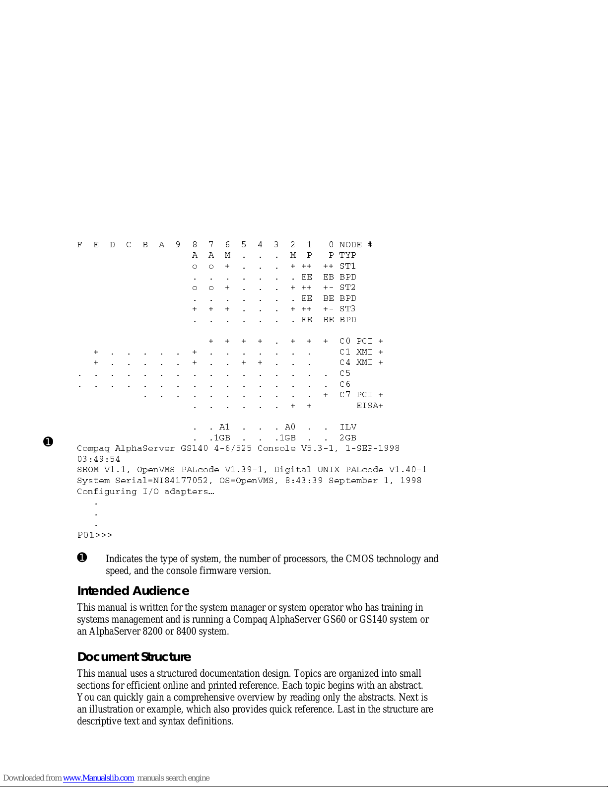
➊
Example 1 Sample GS140 Console Display
*)('&%23()
%%11448=4
SS78
)))&&4(
SS78
))&)&4(
78
))&)&4(
'4'-
'<1-
'<1-
'
'
'4'-
)-7%
%%-0:
+&+&+&
'SQTEU%PTLE7IVZIV+7'SRWSPI:7)4
7631:3TIR:174%0GSHI:(MKMXEP92-<4%0GSHI:
7]WXIQ7IVMEP!2-37!3TIR:177ITXIQFIV
'SRJMKYVMRK-3EHETXIVW|
4"""
➊
Indicates the type of system , t he num be r of proce ssors, the CMOS technol ogy a nd
speed, and the console fi rmware ve rsion.
Intended Audience
This manual is written for the system manager or system operator who has training in
systems management and i s running a Compa q Alpha Serve r GS60 or GS140 system or
an AlphaServer 8200 or 8400 system.
Document Structure
This manual uses a structured doc um ent a ti on de sign. Topi c s are organi z ed i nt o smal l
sections for efficient online and printed reference. Each topic begins with an abstract.
You can quickly gain a com pre hensive ove rvie w by rea ding onl y t he a bstra ct s. Next i s
an illustration or example, which also provides quick reference. Last in the structure are
descriptive text a nd synta x defi ni ti ons.
xiv
Page 15

This manual has eight c ha pte rs and t hree a ppendi xe s, a s follows:
• Chapter 1, Introduction, provides a brief overview of the Alpha Server 8200
and AlphaServer 8400 hardware, firm ware , and system a rchi t ec t ure.
• Chapter 2, AlphaServer 8200 System, and Chapter 3, AlphaServer 8400
System, gi ve a ba sic int roduc ti on to your system a nd it s part s.
• Chapter 4, I/O Subsystems, describes the AlphaServer 8200 a nd AlphaServe r
8400 systems’ I/O design.
• Chapter 5, Booting an Operating System, tells how to start running t he
Windows NT, OpenVMS, and DIGITAL UNIX operating systems.
• Chapter 6, System Troubleshooting, provides basic troubleshooting
procedures.
• Chapter 7, SRM Console Com ma nds, lists the SRM console commands with
an example of each command.
• Chapter 8, AlphaBIOS Firmware, describes the AlphaBIOS menu sele c ti ons
and boot screen.
• Appendix A, O penVMS and DIGITAL UNIX B oo t O pt i o ns, lists the options
used with the boot command for OpenVMS and DIGITAL UNIX to control
various phases of booting.
• Appendix B, Updat i ng F irmware , explains how to run the Loada ble Firm ware
Update (LFU) utility.
• Appendix C, Runni ng Co nfiguratio n Ut ilities from the SRM Console,
explains how to run the configuration utilities required when installing some
options.
xv
Page 16

Table 1 AlphaServer GS60/140 and 8200/8400 Documentation
Title Order Number
Hardware User Information and Installation
Operations Manual
Site Preparation Guide
AlphaServer GS60/8200 Installation Guide
AlphaServer GS140/8400 Installation Guide
KFE72 Installation Guide
AlphaServer GS60/140 8200/8400 Windows NT
EK–T8030–OP
EK–T8030–SP
EK–T8230–IN
EK–T8430–IN
EK–KFE72–IN
EK–T8WNT–RN
Administrator’s Guide and Release Notes
Service Information Kit QZ–00RAC–GC
Service Manual (hard copy) EK–T8030–SV
Service Manual (diskette ) AK–QKNFB–CA
AK–QUW7B–CA
AK–QUW6B–CA
Reference Manuals
System Technical Manual
System Technical Manual Supplement : CP U
System Technical Manual Supplement : Me mory
DWLPA/DWLPB PCI Adapter Technical Manual
EK–T8030–TM
EK–T8030–TS
EK–MS7CC–TS
EK–DWLPA–TM
Upgrade Manuals for All Systems
KN7CC CPU Module Installation Card
KN7CD CPU Module Installation Card
KN7CE CPU Module Installation Card
KN7CF CPU Module Installation Card
KN7CG CPU Module Installation Card
MS7CC Memory Installation Card
KFTHA System I/O Module Installation Guide
KFTIA Integrated I/O Module Installat ion Guide
xvi
EK–KN7CC–IN
EK–KN7CD–IN
EK–KN7CE–IN
EK–KN7CF–IN
EK–KN7CG–IN
EK–MS7CC–IN
EK–KFTHA–IN
EK–KFTIA–IN
Page 17

Introduction 1-1
Chapter 1
Introduction
The AlphaServer 8200 and 8400 systems are high-performance, symmetric
multiprocessing systems that are suitable for office and datacenter environments. They
offer access to multiple high-bandwidth I/O buses, very large memory capacities, up to
14 high-performance Alpha CPUs, and many other features normally associated with
mainframe systems.
This chapter introduces the AlphaServer 8200 and AlphaServer 8400 systems. There
are three sections:
•
AlphaServer 8200/8400 System Overview
•
Firmware and Utilities Overview
•
System Architecture
Page 18

1-2 AlphaServer 8200/8400 Operations Manual
1.1 AlphaServer 8200/8400 System Overview
The AlphaServer 8200 and 8400 systems are separate, but related, systems that
use the same system bus, the TLSB. The processor, memory, and I/O adapter
units that can be configured on this bus are also the same. The cabinets, and
some of their components, vary.
Figure 1-1 AlphaServer 8200 and 8400 Systems
BX-0118-95
8400 8200
Page 19

Introduction 1-3
AlphaServer 8200 System
The AlphaServer 8200 system main cabinet contains the processor system unit (PSU)
including a five-slot card cage, power regulators, and space for PCI I/O shelves or
StorageWorks shelves. The 8200 system can have up to two expander cabinets,
containing additional PCI I/O shelves and StorageWorks shelves.
AlphaServer 8400 System
The AlphaServer 8400 system main cabinet contains the nine-slot TLSB card cage
with processor, memory, and I/O modules, power regulators, and one or more plug-in
units for I/O, disks, and batteries. The 8400 system can have up to two expander
cabinets and additional plug-in units for I/O, disks, and batteries. The 8400 system can
also have up to two battery cabinets to provide battery backup. Chapter 3 covers the
AlphaServer 8400 system.
Chapter 4 describes the I/O subsystem for both 8200 and 8400 systems. Booting an
operating system is discussed in Chapter 5, basic troubleshooting in Chapter 6, SRM
console commands in Chapter 7, and AlphaBIOS firmware operations in Chapter 8.
AlphaServer 8200/8400 Options
The DIGITAL Systems and Options Catalog describes all options for AlphaServer
8200 and AlphaServer 8400 systems. In addition, DIGITAL maintains a list of the
latest supported options on the Internet, which you can access as follows:
Using ftp, copy the file:
ftp.digital.com/pub/Digital/Alpha/systems/as8400/docs/8400-options.txt
Using a Web browser, follow links from the URL:
http://www.digital.com/info/alphaserver/products.html
Page 20

1-4 AlphaServer 8200/8400 Operations Manual
1.2 Firmware and Utilities Overview
Firmware residing in flash ROM on CPU and other modules in the system
provides commands for booting the operating system, testing devices and I/O
adapters, and other tasks useful in operat ing and maintaining a running system.
You type the commands or select from menus at the console device.
Figure 1-2 Accessing Firmware at the Console Device
BX-0618D-98
digital
LA75
Companion Printer
Page 21

Introduction 1-5
SRM Console
The SRM console firmware is the first to be executed after system self-test when the
system is powered up. If you have requested automatic boot (see Chapter 5), the
operating system is booted automatically. Otherwise, the system halts at the SRM
console prompt. The SRM console provides commands for booting the OpenVMS and
DIGITAL UNIX operating systems, and for testing adapters and I/O devices on all
operating systems. The SRM console command alphabios transfers control to
AlphaBIOS firmware to boot Windows NT.
You can update firmware from the CD-ROM disk using either SRM console
commands or AlphaBIOS Setup menus. The SRM console firmware resides in flash
ROM on the CPU modules.
AlphaBIOS Firmware
The AlphaBIOS firmware allows you to boot the Windows NT operating system, view
and change configuration information, and perform maintenance tasks in the Windows
NT environment. You can also update firmware, including the SRM console,
AlphaBIOS firmware, and I/O device firmware. The AlphaBIOS firmware is on the
same CD-ROM as the SRM console firmware, which is updated periodically. When
loaded, the firmware resides in flash ROM in the CPU modules.
LFU (Loadable Firmware Update Utility)
Boot this utility (with the SRM boot command, or, for Windows NT systems, from the
Updating AlphaBIOS menu item) whenever you need to update the SRM console
firmware, the AlphaBIOS firmware, or I/O device firmware. The CD is updated
periodically.
SCSI Configuration Utilities
The SRM console run command lets you run four SCSI-related utilities:
•
RCU—RAID Configuration Utility
•
SWXCRFW—Updates firmware on the RAID controller
•
EEROMCFG—ISP1020 EEPROM configuration utility
• UTIL_CLI—KZPSA configuration utility
The first two utilities are on a floppy diskette; the latter two, on a CD-ROM.
EISA Configuration Utility
The EISA Configuration Utility (ECU) can be run from:
• The SRM command runecu, to configure EISA options in the DWLPA/DWLPB
card cage when either the KFE70 or KFE72 adapter option is installed. This
command can be used with the OpenVMS or DIGITAL UNIX operating systems.
• One of the AlphaBIOS “Utilities” menu items, used as part of the KFE72
installation procedure for Windows NT systems.
Page 22

1-6 AlphaServer 8200/8400 Operations Manual
1.3 System Architecture
The high-speed TLSB system bus is used to interconnect processors, memory
modules, and I/O port modules.
Figure 1-3 Sample System Architecture
I/O Bus
BX0501-94
Memory
I/O
Port
System Bus
Processors
Devices
I/O Bus
Adapter
I/O
Controller
I/O
Controller
I/O
Controller
Devices
Devices
Page 23

Introduction 1-7
The TLSB bus is a synchronous bus (with a 256-bit data bus and a 40-bit
command/address bus) that interconnects processors, memory modules, and the I/O
port. The I/O port (KFTHA or KFTIA) module connects the TLSB bus to I/O buses
through separate I/O adapter modules.
The TLSB bus uses the concept of a node. The TLSB bus has three types of nodes:
processors, memories, and I/O port controllers.
A processor node is a single module. It consists of one or two scalar processors, the
shared TLSB bus interface, separate cache, and support logic.
In a multiprocessing system, one processor becomes the boot processor during powerup, and that boot processor loads the operating system and handles communication
with the operator console. The other processors become secondary processors and
receive system information from the boot processor. The AlphaServer 8200 can have
up to three processor modules for a total of six CPUs. The AlphaServer 8400 can have
up to seven processor modules for a total of 14 CPUs.
A memory node is one memory module. Memory is a global resource equally
accessible by all processors on the TLSB. Memory modules can have 128, 256, or 512
Mbytes or 1, 2, or 4 Gbytes of memory with ECC and associated control logic. The
memories are automatically interleaved when the system is configured with multiple
memory banks. The 8200 system supports up to three memory modules; the 8400
supports up to seven.
The I/O port module (KFTHA) or integrated I/O module (KFTIA) provides the
interface between the TLSB and the I/O subsystem. The KFTHA provides
connections for up to four I/O buses using cables called hoses. For OpenVMS and
DIGITAL UNIX systems, these buses include the PCI/EISA, Futurebus+, or XMI
buses. For Windows NT, only PCI buses are supported. The KFTIA provides a
connection to one I/O subsystem, with the same possibilities for the operating system
as were noted for a KFTHA. In an 8200, only PCI buses are supported, regardless of
operating system.
In Figure 1–3, the I/O bus adapter can be the DWLPA/DWLPB module for the PCI,
the DWLAA module for the Futurebus+, and the DWLMA module for the XMI.
NOTE: The DWLPA is not supported with the Windows NT operating system; you
must have a DWLPB in this case.
The PCI I/O bus adapter module connects to various interconnects such as SCSI,
FDDI, Ethernet, NVRAM, and, with OpenVMS and DIGITAL UNIX systems, EISA
bus interfaces.
The Futurebus+ I/O bus adapter module connects to various interconnects such as
SCSI and FDDI.
The XMI I/O bus adapter module connects to various interconnects such as CI,
SDI/STI, SCSI, FDDI, and Ethernet..
Page 24

Page 25

AlphaServer 8200 System 2-1
Chapter 2
AlphaServer 8200 System
The DIGITAL AlphaServer 8200 system, designed for use in an office environment,
can support many users in a time-sharing environment. The 8200 system:
• Supports the full range of system applications of OpenVMS, DIGITAL UNIX,
and Windows NT operating systems
• Allows for expansion of processors, memory, and I/O
• Uses a high-speed system interconnect bus (TLSB bus), which has a peak
bandwidth of 2.4 Gbytes/sec.
• Supports up to 12 Gbytes of physical memory
• Provides optional self-contained uninterruptible power system (UPS) capability
that supports the system in case of power failure
• Performs automatic self-test on power-up, reset, reboot, or system initialization
• Operates as a standalone system, a member of a cluster, or as a boot node of a
local area cluster
This chapter describes the system package and the location of components in the
cabinet. Sections include:
• System Characteristics
• Sample 8200 System
• System Front View
• System Rear View
• System Components (Processor System Unit, Cabinet Control Logic Panel,
Console Load Device, and Power System)
• Controls and Indicators
– Control Panel
– AC Power Circuit Breaker
• Options
Page 26

2-2 AlphaServer 8200/8400 Operations Manual
2.1 System Characteristics
Figure 2-1 shows the cabinet dimensions and the required clearance space. The
tables list the electrical and environmental characteristics.
Figure 2-1 Sample System Footprint
Rear
Clearance
75 cm (29.5 in)
Front
Clearance
100 cm (40 in)
BX-0600-94
Width
180 cm (71 in)
Depth
267.5 cm
(106 in)
92.5 cm
(36.4 in)
System
Cabinet
Expander
Cabinet
Expander
Cabinet
Expander
Cabinet
60 cm (23.6 in)
170 cm (67 in)
System
Cabinet
Expander
Cabinet
60 cm (23.6 in) 60 cm (23.6 in)
170 cm (67 in)
170 cm (67 in)
Page 27

AlphaServer 8200 System 2-3
The values in Table 2–1 and Table 2–2 apply to the system cabinet only. The values
are configuration dependent.
Table 2-1 Electrical Characteristics
Electrical Specification
Single-phase AC input voltage
(nominal)
202–240 (208) – North America
202–240 (230) – Europe/AP
202–240 (202) – Japan
Nominal frequency 50–60 Hz
AC current (nominal) 16 A (202 V)
AC current (maximum) 30 A – North America
32 A – Europe/AP
30 A – Japan
AC power consumption (maximum) 2.6 KW
Table 2-2 Environmental Characteristics
Environmental Operating Storage
Heat dissipation (maximum) 9,100 Btu/hr
Temperature 10°C–35°C
(50°F–95°F)
-40°C–66°C
(-40°F to 151°F)
Relative humidity 10–90% 10–95%
Altitude 0–2.4 km
(0–8000 ft)
0–9.1 km
(0–30,000 ft)
Page 28
2-4 AlphaServer 8200/8400 Operations Manual
2.2 Sample 8200 System
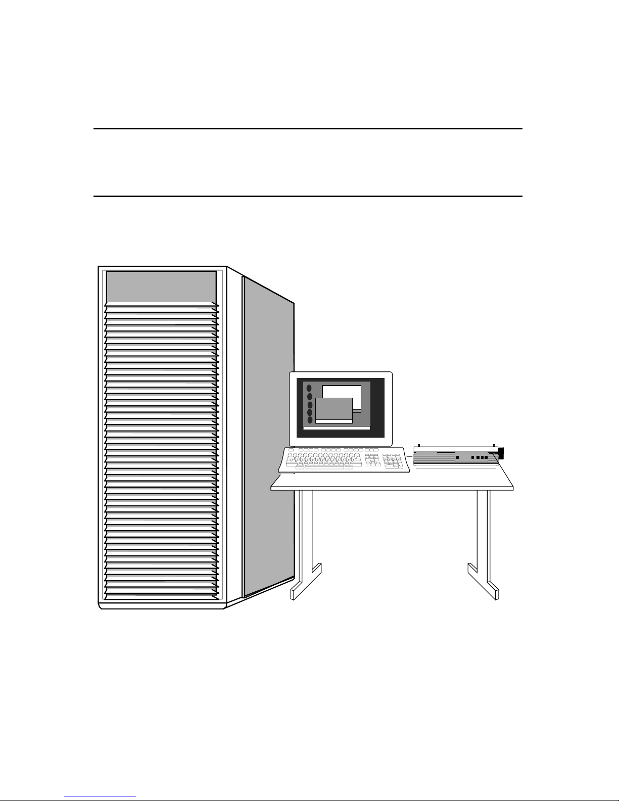
Figure 2-2 shows a sample system. The system includes a console terminal and
printer, an accessories kit, and a documentation set, which includes this manual.
The system can have up to two optional expander cabinets, additional disk drives,
and optional battery backup.
Figure 2-2 Sample 8200 System
BX-0618D-98
digital
LA75
Companion Printer
Page 29

AlphaServer 8200 System 2-5
Your DIGITAL customer service engineer has installed your system and verified that
it is running properly. Before you turn on the system, familiarize yourself with its
components:
• The system cabinet houses the power system (with optional battery backup) and
the processor system unit (PSU) which contains a storage drawer, the TLSB card
cage, control panel, the cabinet control logic panel, and a CD-ROM drive.
Optional hardware includes StorageWorks shelves and PCI shelves.
• The console load device is used for installing operating systems and software.
• The console device is used for booting and for system management operations.
The console device must include a serial console monitor, and, for Windows NT
systems, must also include a graphics monitor (shown in Figure 2-2).
• The console printer provides a hardcopy record of system operations.
• Optional I/O components include PCI shelves and StorageWorks shelves. These
shelves are installed in the system or expander cabinets to provide space for I/O
and disk options.
• Optional expander cabinets provide additional space for PCI I/O devices and
disk drives.
• A system documentation kit.
Page 30

2-6 AlphaServer 8200/8400 Operations Manual
2.3 System Front View
With the front door open, you can see the control panel, the TLSB card cage,
blower, PCI shelves, StorageWorks shelves, and power regulators.
Figure 2-3 System Front View
BX-0604B-97
Front
Enable
Run
Fault
On/Off
Secure
Restart
TM
2.88
Console
External
Enable (XMI/FBUS)
PowerComm 3
PowerComm 2
PowerComm 1
External
UPS Power
External
Power Enable
Expander
TLSB
Card Cage
StorageWorks Power
Supply
StorageWorks Drive
Control Panel
CCL Panel
StorageWorks Shelves
Space for
Power Regulators
CD-ROM Drive
Floppy Drive
PCI Shelf
MODULEOK
OVERVOLTAGE
OVERTEMP
ON BATTERY
BATTERYCHARGING
REPLACEBATTERY
+48VDC-
+48VDC-
CURRENT
SHARE
9SIGNALS 1
10 2
Page 31

AlphaServer 8200 System 2-7
The following components are visible from the inside front of the cabinet:
• TLSB card cage
• CD-ROM drive
• Floppy drive
• Control panel
• Cabinet control logic (CCL) panel
• PCI or StorageWorks shelves
• Power regulators
NOTE: Four optional storage devices installed in the processor system unit are not
visible. You access these devices from the front of the cabinet by sliding out the
removable storage drawer from the processor system unit.
Page 32

2-8 AlphaServer 8200/8400 Operations Manual
2.4 System Rear View
With the rear door open, DIGITAL customer service engineers can access the
circuit breaker and AC power cord.
Figure 2-4 System Rear View
BX-0605A-97
Rear
PCI or StorageWorks
Shelves
Space for
Power Regulators
TLSB
Card Cage
Blower
Circuit Breaker
Page 33

AlphaServer 8200 System 2-9
The following components are visible from the inside rear of the cabinet:
• TLSB card cage
• Blower
• PCI or StorageWorks shelves
• Power regulators
• Circuit breaker
Optional components visible from the inside rear (and front) of the cabinet include PCI
shelves, StorageWorks shelves, and an additional power regulator.
Page 34

2-10 AlphaServer 8200/8400 Operations Manual
2.5 System Components
2.5.1 Processor System Unit
The processor system unit (PSU) contains the 5-slot TLSB card cage and blower,
a storage drawer housing integrated I/O devices, an optional floppy drive, a
cabinet control logic (CCL) panel, and the control panel.
Figure 2-5 Processor System Unit
BX-0606-94
Front
Enable
Run
Fault
On/Off
Secure
Restart
TM
2.88
Console
External
Enable (XMI/FBUS)
PowerComm 3
PowerComm 2
PowerComm 1
External
UPS Power
External
Power Enable
Expander
Page 35

AlphaServer 8200 System 2-11
The PSU is located in the upper half of the system cabinet, as viewed from the front.
The PSU storage drawer can house up to six optional SCSI devices, including one
5.25-inch removable media device and five 3.5-inch devices. The 5.25-inch device
and one 3.5-inch device are accessible from the front of the cabinet; the other four 3.5inch devices are accessible from the rear of the cabinet.
The TLSB card cage slots are numbered 4 through 8 from right to left in the front of
the cabinet. See Figure 2-6. The card cage contains one KFTIA or KFTHA module,
one CPU module, and one memory module as a minimum configuration. A KFTIA or
KFTHA module is always installed in slot 8.
The blower cools the card cage.
Figure 2-6 TLSB Card Cage
BX-0609B-97
Front
8
7
6
5
4
First CPU
CPUs, Memories, or Third I/O Module
CPUs or Memories
First Memory or Second I/O Module
KFTIA or KFTHA I/O Module
Page 36

2-12 AlphaServer 8200/8400 Operations Manual
2.5.2 Cabinet Control Logic Panel
Console terminal I/O and expander cabinet remote power control/status
connections are located on the cabinet control logic (CCL) panel to the right of
the control panel. See Table 2-3 for a list of the other connections shown in
Figure 2-7.
Figure 2-7 Cabinet Control Logic Panel
Console
External
Enable (XMI/FBUS)
PowerComm 3
PowerComm 2
PowerComm 1
External
UPS Power
External
Power Enable
Expander
BX-0000-94
Page 37

AlphaServer 8200 System 2-13
Table 2-3 Control/Status and I/O Connections
Connector Name Function
Console Serial console device connection for
OpenVMS, DIGITAL UNIX, and
Windows NT systems.
(For Windows NT systems, the graphics
monitor is connected through the KFE72
adapter installed in the primary DWLPB
adapter (connected to hose 1 on the
KFTHA or KFTIA in slot 8 of the TLSB).
Expander Expander cabinet power supply control
connection.
NOTE: The expander cabinet connector is
not intended to be connected to a public
telecommunications network.
Power Comm3 Reserved for future use.
Power Comm2 Power supply 2 signal and control
connection.
Power Comm1 Power supply 1 signal and control
connection.
External Enable XMI /FBUS+ Reserved for future use.
External UPS Power Battery backup option connection.
External Power Enable Enables power to PCI and StorageWorks
shelves.
Page 38

2-14 AlphaServer 8200/8400 Operations Manual
2.5.3 Console Load Device
The CD-ROM drive is the in-cabinet console load device.
Figure 2-8 Accessing the Console Load Device
BX-0601A-97
CD-ROM
TLSB
KFTIA
(ISP1020 Controller)
or
KFTHA
(KZPAA in PCI shelf)
Page 39

AlphaServer 8200 System 2-15
The console load device is used for:
• Installing or updating firmware or software
• Loading a backup utility program
• Interchanging user data
• Updating module firmware
The CD-ROM drive is the console load device. It is installed in the system cabinet and
is used to access software and online documentation. Access to the CD-ROM is
provided directly through a KFTIA module or through the PCI subsystem through a
KFTHA module.
Page 40

2-16 AlphaServer 8200/8400 Operations Manual
2.5.4 Power System
The power system consists of one or two power regulators (with optional battery
backup), a cabinet control logic (CCL) module, and power distribution and
signal interconnect cables. The AC circuit breaker controls power to the entire
system.
Figure 2-9 Power System
BX-0603-94
Front
Rear
Power
Regulators
J1
J2
J3
Power
Strip
MODULEOK
OVERVOLTAGE
OVERTEMP
ONBATTERY
BATTERYCHARGING
REPLACEBATTERY
+48VDC-
+48VDC-
CURRENT
SHARE
9SIGNALS 1
10 2
MODULEOK
OVERVOLTAGE
OVERTEMP
ONBATTERY
BATTERYCHARGING
REPLACEBATTERY
+48VDC-
+48VDC-
CURRENT
SHARE
9SIGNALS 1
10 2
Page 41

AlphaServer 8200 System 2-17
The power regulator is located in the lower third of the cabinet. The CCL panel is
located in the processor system unit (PSU), next to the control panel.
The system can have up to two power regulators. In this configuration an optional
power strip is installed at the rear of the cabinet so that only one AC input connection
is required. In a dual power supply system the regulators are used in parallel, one for
the required load plus an additional power regulator for backup in case of failure.
Each power regulator has an AC input assembly, a 48 VDC power regulator, two
cooling fans, indicator lights, and optional battery backup (charger module and battery
packs for UPS operation).
Each power regulator has a circuit breaker; access is from the rear of the cabinet.
Page 42

2-18 AlphaServer 8200/8400 Operations Manual
2.6 Controls and Indicators
This section describes the control panel and the AC power circuit breaker.
Figure 2-10 Control Panel
Front
Enable
Run
Fault
On/Off
Secure
Restart
TM
BX-0607-98
Table 2-4 Control Panel Pushbuttons
Pushbutton Position Effect
On/Off In Supplies power to the PSU. When this button is pressed and
the Secure button is not pressed, OpenVMS or DIGITAL
UNIX users can interrupt operating system program
execution and enter console mode by typing Ctrl/P at the
console device.
Out Removes 48 VDC power from the system. This position is
useful to field service when they wish to power down the
system in an orderly way, prior to switching the system off
completely while replacing or installing a new piece of
hardware.
Page 43

AlphaServer 8200 System 2-19
Table 2-4 Control Panel Pushbuttons (Continued)
Pushbutton Position Effect
Secure In Prevents input from the console device.
On DIGITAL UNIX or OpenVMS systems, used to protect
inadvertent or inadvisable entry into SRM console mode by
typing Ctrl/P at the console device. For example, you might
push this button in when a critical program is running, in case
someone might unknowingly try to enter SRM console mode
to load new console code or otherwise use the console device.
For Windows NT systems, the Secure pushbutton is used in
controlling transitions from the Windows NT operating
system to the SRM console, as described in Section 8.2.
Out Allows input from the console device. See above.
Restart In Momentary switch used to reinitialize the system. Registers
are reinitialized and system self-test starts running. You can
thus restart the system without removing power from the
system, which can cause wear and tear on the machine.
Table 2-5 Control Panel Indicator Lights
Light Color State Meaning
Enable Green On Power is supplied to entire system.
Off Power is removed from the system.
Run Green On Console firmware has passed control to the
operating system.
Off System is in console mode or powered off.
Fault Yellow On Fault on system bus.
Slow
Flash
Power sequencing is in progress or airflow error is
detected.
Fast
Flash
Power system error.
Off No faults were found.
Page 44

2-20 AlphaServer 8200/8400 Operations Manual
2.6.1 AC Power Circuit Breaker
The circuit breaker is located on the power regulator at the rear of the cabinet.
Figure 2-11 Circuit Breaker
BX-0608-94
Rear
Up Position: On
Down Position: Off
Page 45

AlphaServer 8200 System 2-21
Each power regulator has a circuit breaker.
The circuit breaker controls power to the entire system.
For normal operation, the circuit breaker must be in the on position, in which the
handle is pushed up. To shut the circuit breaker off, push the handle down.
Page 46

2-22 AlphaServer 8200/8400 Operations Manual
2.7 Options
System options include a floppy drive, PCI shelves, StorageWorks shelves, an
additional power regulator, and optional battery backup.
Figure 2-12 System Options
BX-0604A-94
Front
Enable
Run
Fault
On/Off
Secure
Restart
TM
2.88
Console
External
Enable (XMI/FBUS)
PowerComm 3
PowerComm 2
PowerComm 1
External
UPS Power
External
Power Enable
Expander
Space for PCI or
StorageWorks Shelves
Space for Additional
Power
MODULEOK
OVERVOLTAGE
OVERTEMP
ON BATTERY
BATTERYCHARGING
REPLACEBATTERY
+48VDC-
+48VDC-
CURRENT
SHARE
9SIGNALS 1
10 2
Page 47

AlphaServer 8200 System 2-23
PCI I/O
PCI I/O is used in the 8200 system. The PCI shelf has 12 slots, a PCI adapter module,
a hose interface to the TLSB bus, and a power supply. The KFE70 adapter provides a
bridge module for access to EISA I/O. The KFE72 adapter provides a graphics and
keyboard and mouse ports for a system using a graphics console monitor. A maximum
of three PCI shelves can be installed in the main cabinet.
StorageWorks Shelf
A maximum of six StorageWorks shelves can be installed in the main cabinet. Two
shelves can be installed in the same vertical space; one shelf at the front of the cabinet
and one shelf at the rear of the cabinet.
Additional Power Regulator
An additional power regulator may be installed for backup in case the other power
regulator fails.
Battery Backup Option
A power regulator can be equipped with the battery backup option (a charger module
and battery packs) to provide uninterrupted power in case of a power failure.
Page 48

Page 49

AlphaServer 8400 System 3-1
Chapter 3
AlphaServer 8400 System
The DIGITAL AlphaServer 8400 system is designed for growth, offering
configuration flexibility, an outstanding I/O subsystem, and expansion capability in a
single or multi-cabinet environment. Functionally, this system is identical to the
AlphaServer 8200 system. The 8400 system, however, can have:
• Up to six or seven processor modules for a total of 12 or 14 CPUs (see details in
the supported options catalog).
• Up to seven memory modules for a total of 28 Gbytes of memory.
• A three-phase power system with optional battery backup.
• For OpenVMS and DIGITAL UNIX systems, options include XMI, FBUS+, and
PCI/EISA I/O bus plug-in units (PIUs), and StorageWorks PIUs. For Windows
NT systems, options include PCI I/O bus plug-in units.
This chapter describes the AlphaServer 8400 system package, introduces the location
of components in the cabinet—both front and rear views; and describes the system
controls and indicators. Sections include:
• System Characteristics
• Sample 8400 System
• System Front View
• System Rear View
• System Components
• Controls and Indicators
Page 50

3-2 AlphaServer 8200/8400 Operations Manual
3.1 System Characteristics
DIGITAL AlphaServer 8400 charac teristics are shown in Table 3-1 and Table 3-
2. Figure 3-1 shows a system footprint.
Figure 3-1 Sample System Footprint
Rear
Clearance
100 cm (39 in)
Front
Clearance
150 cm (59 in)
BX0500-94
Width
240 cm (94.5 in)
Depth
337.5 cm
(132.5 in)
87.5 cm
(34.5 in)
System
Cabinet
Expander
Cabinet
Expander
Cabinet
Expander
Cabinet
80 cm (31.5 in)
170 cm (67 in)
System
Cabinet
Expander
Cabinet
80 cm (31.5 in) 80 cm (31.5 in)
170 cm (67 in)
170 cm (67 in)
Page 51

AlphaServer 8400 System 3-3
The values in Table 3-1 apply to the 8400 system cabinet only. The values are
configuration dependent. Additional options will increase electrical requirements so
that an additional power regulator may be needed.
Table 3-1 Electrical Characteristics
Electrical Specification
3-phase AC input voltage
(current, maximum)
120/208 V Wye (30A) – North America
380–415 V Wye (30 A) – Europe/AP
202 V Delta (16 A) – Japan
Nominal Frequency 50–60 Hz
AC power consumption
(maximum)
4.6 KW
Table 3-2 Environmental Characteristics
Environmental Operating Storage
Heat dissipation 15,700 Btu/hr –
Temperature¹ 15º–28º C (59º–82º F) -40º–66º C (-40º–151º F)
Relative humidity
x
20–80% 10–95%
Altitude 0–2.4 km (0–8200 ft) 0–9.1 km (0–30,000 ft)
¹
Recommended operating temperature is 18º–24º C (65º–75º F) and 40–60% relative humidity.
Page 52

3-4 AlphaServer 8200/8400 Operations Manual
3.2 Sample 8400 System
Figure 3-2 shows a sample AlphaSer ver 8400. The system includes a CD-ROM
drive, a console device and printer, an accessories kit, and a documentation set.
The system options include battery backup PIUs, three different types of I/O bus
PIUs (depending on the operating system) and StorageWorks disk drive.
Expander cabinets can be added for options.
Figure 3-2 Sample System
digital
LA75
Companion Printer
BX0502A-98
Page 53

AlphaServer 8400 System 3-5
Your DIGITAL customer service engineer has installed your system and verified that
it is running properly. Before you turn on the system, familiarize yourself with its
components:
• The system cabinet houses the TLSB card cage, power system, cooling system,
the control panel with status indicators, and a CD-ROM drive. Optional hardware
includes disk plug-in units (PIUs), battery PIUs, and I/O PIUs.
• The CD-ROM drive is the console load device and is used for installing operating
systems and software.
• The console device is used for booting and for system management operations.
The console device must include a serial console monitor, and also a graphics
monitor (for Windows NT systems).
• The console printer provides a hardcopy record of system operations.
• Optional PIUs include, for OpenVMS and DIGITAL UNIX systems, the XMI
PIU, Futurebus+ PIU, PCI PIU, SCSI PIU, and the battery PIU. For Windows NT
systems, a PCI PIU is included. These plug-in units are installed in the system or
expander cabinets to provide space for I/O, disk, and battery options.
• Optional expander cabinets provide additional space for battery, I/O, and disk
options.
• A system documentation kit.
Page 54

3-6 AlphaServer 8200/8400 Operations Manual
3.3 System Front View
The control panel, plug-in unit panels, and CD-ROM and optional f loppy drive
are on the front of the system cabinet. With the front door open, DIGITAL
customer service engineers can access the TLSB card cage, the power regulator,
cooling system, and optional plug-in units.
Figure 3-3 System Front View
BX0503-98
Front
Blower
Control
Panel
Power
Regulator(s)
TLSB
Card Cage
CD-ROM
Drive
Optional PIUs
Floppy
Drive
Page 55

AlphaServer 8400 System 3-7
These components are visible from the inside front of the cabinet (see Figure 3-3 for
their location):
• Control panel
• CD-ROM drive
• Optional floppy drive
• Power regulator(s) (48 VDC)
• TLSB card cage (holds CPU/memory; slots 0–3)
• Cooling system (blower)
Optional components visible from the inside front include:
• I/O devices
• I/O plug-in unit (PIU)
• Battery PIU
Page 56

3-8 AlphaServer 8200/8400 Operations Manual
3.4 System Rear View
With the rear door open, DIGITAL customer service engineers can access the
TLSB card cage, DC distribution box, battery connections, AC power cord,
circuit breaker, blower, and I/O PIU area.
Figure 3-4 System Rear View
BX0504-98
Rear
DC
Distribution
Blower
Battery
Connections
AC
Power Cord
Circuit
Breaker
TLSB
Card Cage
I/O Module
Optional I/O
Bulkhead
Page 57

AlphaServer 8400 System 3-9
The following components are visible from the rear of the cabinet (see Figure 3-4):
• TLSB card cage (slots 4–8)
• I/O port module (slot 8)
• DC distribution box
• Battery PIU connections
• AC power cord and connector
• Circuit breaker
• Blower
• I/O PIU area
Optional components visible from the inside rear include:
• I/O PIUs
• Battery PIU
Page 58

3-10 AlphaServer 8200/8400 Operations Manual
3.5 System Components
3.5.1 Console Load Device
The CD-ROM drive is the in-cabinet console load device.
Figure 3-5 Accessing the Console Load Device
BX-0601A-97
CD-ROM
TLSB
KFTIA
(ISP1020 Controller)
or
KFTHA
(KZPAA in PCI shelf)
Page 59

AlphaServer 8400 System 3-11
The console load device is used for:
• Installing or updating software
• Loading a backup utility program
• Interchanging user data
• Updating module firmware
The CD-ROM drive is the console load device. It is installed in the system cabinet and
is used to access software and online documentation. Access to the CD-ROM is
provided directly through a KFTIA module or through the PCI subsystem through a
KFTHA module.
Page 60

3-12 AlphaServer 8200/8400 Operations Manual
3.5.2 Power System
The power system includes an AC input box, DC distribution box, power
regulator(s), cabinet control logic module, power distribution cables, signal
interconnect cables, and an optional battery PIU (with H7263-AC/AD regulators
only).
Figure 3-6 Power System
Front
Power
Regulators
Rear
CCL Module
BX-0506B-97
DC Distribution Box
AC Input Box
Page 61

AlphaServer 8400 System 3-13
The power system uses H7263 power regulators (see Figure 3-6), requiring three-phase
AC. Two types of H7263 regulators are available. The H7263–AA/AB regulators
(optional) have the ability to use and charge optional battery packs. The H7263–
AC/AD regulators, shipped with a standard 8400 system, do not allow battery backup.
Both types of power regulator allow switching between regulators in the event one
fails. Power regulator filler modules are used in unused slots to help direct airflow.
The DC distribution box and AC input box are located on the upper left of the system
cabinet (when viewing the system cabinet from the rear). The 48 VDC power
regulators are located at the upper right side (when viewing the system cabinet from
the front).
The AC input box provides the interface for the system to the AC utility power. The
main input circuit breaker, on the AC input box, contains a circuit breaker trip
indicator to indicate an open circuit breaker. The DC distribution box connects the AC
input box and power regulators. It distributes the 48 VDC power.
NOTE: Additional options can increase the power requirements so that an additional
power regulator may be needed.
The cabinet control logic (CCL) module has a yellow power LED. When this LED is
on, the CCL module is receiving 48 VDC power from the power regulators.
Battery backup capability can be provided in systems with H7263–AA/AB regulators
by the addition of the optional battery PIU. The battery PIU is mounted in the bottom
of the system cabinet and provides approximately 11 minutes of operating time in N+1
configured systems.
Page 62

3-14 AlphaServer 8200/8400 Operations Manual
3.5.3 TLSB Card Cage
The TLSB card cage is a 9-slot card cage that contains slots for up to six or seve n
(KN7CF only) CPU modules, up to seven memory array modules, and up to three
I/O modules. The TLSB bus interconnects the CPU, memory, and I/O modules.
Figure 3-7 TLSB Card Cage
Rear
TLSB
Card Cage
BX0507B-97
I/O Module
Front Rear
4
5
6
7
8
0
1
2
3
First CPU
Additional
CPUs
or Memories
Power Filter
I/O Module
First Memory or
Additional I/O Module
Additional CPUs,
Memories, or
I/O Modules
Centerplane
Page 63

AlphaServer 8400 System 3-15
The 9-slot TLSB card cage is located in the upper left (front and rear) of the system
cabinet, as viewed from the front. The TLSB card cage must contain one I/O port
module, which is always installed in slot 8. The other eight slots contain a combination
of KFTHA/KFTIA I/O modules (rear only), memory, and CPU modules.
The TLSB card cage slots are numbered 0 through 3 from right to left in the front of
the cabinet and slots 4 through 8 right to left in the rear of the cabinet.
Page 64

3-16 AlphaServer 8200/8400 Operations Manual
3.5.4 Control/Status and I/O Connections
An I/O connection for the serial console device, and expander cabinet remote
power control/status connections are located to the right of the control panel.
Ethernet and other I/O connections are located off the I/O modules. For the PCI
and FBUS+ PIUs, these connections are directly off the modules. For the XMI
PIU, I/O connections are made off the I/O bulkhead in the lower rear of the
cabinet.
Figure 3-8 Control/Status and I/O Connections
BX0508A-98
Rear
XMI I/O
Bulkhead
Disable
Secure
Enable
Restart
Key On
Run
Fault
Left Expander
Right Expander
Console
Front
Serial Console
Device
Right
Expander
Left
Expander
Remote
Power
Control/Status
Front
PCI
StorageWorks
Rear
Page 65

AlphaServer 8400 System 3-17
Three modular jacks to the right of the control panel allow power control/status
connections to the left expander cabinet, right expander cabinet, and I/O connections to
a serial console terminal. This serial console terminal modified modular jack is keyed
so that an expander cabinet connector cannot be plugged into its jack.
The system cabinet has four quadrants in the bottom of the cabinet.
For OpenVMS and DIGITAL UNIX systems, a PCI or Futurebus+ PIU can be
installed in any of the four quadrants. An XMI PIU requires two quadrants, with the
I/O modules in front and the I/O bulkhead supplying I/O connectors in the back (see
Figure 3-8).
For Windows NT systems, a PCI PIU can be installed in any of the quadrants. A PCI
PIU (DWLPB only) with a KFE72 adapter must be installed off of hose 1 (not hose 0)
of the KFTHA or KFTIA installed in slot 8 of the TLSB. (A graphics monitor,
keyboard, and mouse, required for Windows NT systems, are connected to the KFE72.
Connectors for two serial ports and a parallel port are also supplied with the KFE72.)
Page 66

3-18 AlphaServer 8200/8400 Operations Manual
3.5.5 Cooling System
The cooling system cools the power system, the TLSB card cage, control logic,
and PIUs.
Figure 3-9 Cabinet Airflow
BX0509-94
Page 67

AlphaServer 8400 System 3-19
The cooling system is designed to keep system components at an optimal operating
temperature. It is important to keep the front and rear doors free of obstructions,
leaving a minimum clearance space of 1.5 meters (59 inches) in the front and 1 meter
(39 inches) in the rear between cabinets (see Figure 3-9) to maximize airflow.
The blower, located in the center of the cabinet, draws air downward through the
power regulators and TLSB card cage. It draws air upward through the PIUs. Filler
modules, located in the TLSB card cage, help to direct airflow. Air is exhausted at the
middle of the cabinet front and rear. The blower speed varies based on the system’s
ambient temperature.
CAUTION: Anything placed on top of the cabinet could restrict airflow. This will
cause the system to power down.
Page 68

3-20 AlphaServer 8200/8400 Operations Manual
3.5.6 System Options
System options include a floppy drive beside the CD-ROM, additional power
regulators and additional PIUs for I/O, disks, tapes, and batteries.
Figure 3-10 System Options
BX0510-94
Front
Additional Power
Regulators
Optional PIUs
Page 69

AlphaServer 8400 System 3-21
SCSI Disk and Tape PIUs
A maximum of three SCSI PIUs can be installed in the system cabinet or six in an
expander cabinet. The PIU can occupy any quadrant in the main or expander cabinet.
The PIU can contain up to seven 3.5-inch or two 5.25-inch disks. Supported devices
include SCSI disk drives, CD-ROM, and tape drives.
PCI PIUs
Up to two PCI PIUs can be installed in the system or expander cabinet. A PCI PIU
occupies one quadrant, either Q2 or Q4. A PCI PIU can contain two PCI shelves, each
containing a 12–slot card cage, configured as three 4-slot PCI buses, or one PCI and
one SCSI shelf. EISA options can be used on systems with a KFE70 adapter. A
system with a KFE72 adapter can only contain PCI options (see Chapter 4).
XMI PIUs
A maximum of two XMI PIUs can be installed in the system or expander cabinet on
OpenVMS or DIGITAL UNIX systems. Each XMI PIU occupies two quadrants and
has 14 slots. Twelve slots can contain the following modules: CIXCD, DEMFA,
DEMNA, KZMSA, and KFMSB. One module must be installed in slots 1 or 14. Slot
7 contains the clock module, and slot 8 contains the DWLMA module.
Futurebus+ PIUs
One Futurebus+ PIU can be installed in the system or expander cabinet on OpenVMS
or DIGITAL UNIX systems. The Futurebus+ PIU occupies one quadrant and has 10
slots. The DWLAA module is standard and is installed in slot 5.
Battery PIUs
The system can be equipped with an optional battery PIU to provide power in case of a
power failure. Each regulator requires a battery pack mounted in the bottom of the
system cabinet. The battery PIUs provide a minimum of 8 minutes of full system
operation when fully charged.
Additional Power Regulators
AlphaServer 8400 systems using H7263–AC/AD power regulators, which require 3phase input can have a second or third power regulator installed as backup should a
regulator fail. Systems requiring battery backup must have the H7263–AA/AB
regulators installed.
Older AlphaServer 8400 systems may have one H7264 power regulator, using singlephase AC, and a second may be required depending on the system configuration. This
system has no support for battery backup operation or for N+1 redundancy.
Page 70

3-22 AlphaServer 8200/8400 Operations Manual
3.6 Controls and Indicators
This section introduces the system controls and indicators. The system control
panel, located in the upper right front of the cabinet, contains a keyswitch and
status lights. The keyswitch regulates power going into the system, secures the
console device, and controls system operation.
3.6.1 Control Panel Keyswitch
Figure 3-11 Control Panel Keyswitch
O
BX0511-94
Front
Disable
Secure
Enable
Restart
Key On
Run
Fault
Page 71

AlphaServer 8400 System 3-23
The keyswitch labels can be in English or international versions as shown in
Figure 3-11.
Table 3–3 Keyswitch Positions
Position Effect
Disable
Removes 48 VDC power from the system. Power is still supplied to the
CCL module. This switch is useful for field service when they wish to
power down the system in an orderly way, prior to switching the power
off completely while replacing or installing a new piece of hardware.
Secure Prevents input from the console device.
On DIGITAL UNIX or OpenVMS systems, used to protect against
inadvertent or inadvisable entry into SRM console mode by typing
Ctrl/P at the console device. For example, you might switch the system
to Secure when a critical program is running, to prevent someone from
unknowingly trying to enter SRM console mode.
For Windows NT systems, the Secure keyswitch position is used in
controlling transitions from Windows NT to SRM console mode, as
described in Section 8.2.
Enable Position used while the machine executes programs.
On DIGITAL UNIX or OpenVMS systems, you can interrupt program
execution and enter SRM console mode by typing Ctrl/P at the console
device when the switch is in this position.
Ctrl/P does not work on Windows NT systems. There are several ways
to interrupt program execution on these systems. See Section 8.2 for
instructions on how to switch between Windows NT, AlphaBIOS Setup,
and SRM console mode.
Restart A momentary switch position, used to reinitialize the system. Registers
are reinitialized and system self-test starts running. You can thus restart
the system without removing power from the system, which can cause
wear and tear on the machine.
Page 72

3-24 AlphaServer 8200/8400 Operations Manual
3.6.2 Control Panel Indicator Lights
The control panel has three status indicator lights: Key On, Run, and Fault.
These lights indicate the operating status of the system.
Figure 3-12 Control Panel Indicator Lights
O
BX0512-94
Front
Disable
Secure
Enable
Restart
Key On
Run
Fault
Page 73

AlphaServer 8400 System 3-25
Three status indicator lights (see Figure 3-12) show the state of the system: (Key On)
DC power supplied, (Run) execution, and (Fault) errors. Table 3–4 describes the
conditions indicated by the lights.
Table 3–4 Control Panel Indicator Lights
Light Color State Meaning
Key On Green On Power is supplied to entire system; the blower is
running.
Off Power is supplied only to the cabinet control logic
module.
Run Green On System is executing operating programs or certain
power-up tests.
Off System is in console mode, operating system is not
running, or the system is turned off.
Fault Yellow On Fault on system bus.
Slow
Flash
Power sequencing is in progress or airflow error
is detected.
Fast
Flash
Power system error, airflow error, or keyswitch in
Disable position transition detected.
Off No faults were found.
Page 74

3-26 AlphaServer 8200/8400 Operations Manual
3.6.3 Circuit Breaker and AC Power Indicators
The circuit breaker is located on the left side of the rear of the system cabinet,
just above the blower assembly. With t hree–phase power, the circuit breaker can
be secured in the off position with a lock.
Figure 3-13 Circuit Breaker and AC Power Indicators
BX-0135-94
Rear
Three-Phase Power
Single-Phase Power
Rear
Page 75

AlphaServer 8400 System 3-27
The circuit breaker and power indicators are at the rear of the cabinet.
Circuit Breaker
The circuit breaker controls power to the entire system, including the power regulators,
blower, battery backup, and in-cabinet options. Current overload causes the breaker to
trip to the off position, so that power to the system is turned off.
For normal operation, the circuit breaker must be in the on position, in which the
handle is pushed up. To shut the circuit breaker off, push the handle down.
AC Power Indicators
With three-phase power, the power indicators are located below the circuit breaker
handle. When the system is powered on, the power indicators are red. When the circuit
breaker is off, tripped, or open, the power indicators change to green. When one phase
has tripped, the power indicator for that phase will change to green.
NOTE: The power indicators in the 202V version are different. If one phase trips, all
power indicators trip, so that all indicators are green.
Circuit Breaker Lockout
With three-phase power, the circuit breaker lockout secures the circuit breaker in the
off position. The lockout consists of a hinged plate that is placed over the circuit
breaker handle. A padlock can be placed on the right or left side of the lockout, so that
no one can turn the power on.
Single–Phase Power
On older systems with single-phase power, there are no power indicators with singlephase power, nor is there circuit breaker lockout.
Page 76

Page 77

I/O Subsystems
4-1
Chapter 4
I/O Subsystems
This chapter describes the AlphaServer 8200 and AlphaServer 8400 I/O subsystems.
Sections include:
• I/O Subsystem Overview
• I/O Port Modules
• System Configuration Information
• PCI Adapter
• KFE70 and KFE72 Adapters
• EISA Configuration Utility
Page 78

4-2
AlphaServer 8200/8400 Operations Manual
4.1 I/O Subsystem Overview
Figure 4-1 illustrates CPU, memory, and I/O port module (KFTHA and KFTIA)
interfaces to the system bus.
Figure 4-1 I/O Subsystem
BX-0653-98
System Bus
CPUs
Memory
KFTHA
Controllers
Devices
I/O Bus
Adapter
Hoses
Hose
KFTIA
PCI
3 FWD SCSI Ports
1 SE SCSI Port
2 Ethernet Ports
Controllers
Devices
I/O Bus
Adapter
Hose
1 FDDI Port (optional)
(Integrated PCI bus)
1 NVRAM
Page 79

I/O Subsystems
4-3
The interface from the AlphaServer 8200 and 8400 system bus to I/O is provided by
two types of I/O adapter modules, the KFTHA and the KFTIA. The KFTHA has four
channels, or hoses, to connect to I/O devices (see Figure 4-1). The KFTIA has one
internal hose (an integrated PCI bus) and one hose to connect to external I/O.
Page 80

4-4
AlphaServer 8200/8400 Operations Manual
4.2 I/O Port Modules
The KFTHA module has four channels, or “hoses,” to external I/O subsystems
such as the PCI bus (for any 8200 syste m and 8400 syste ms wit h Wi ndows NT) , or
the PCI, Futurebus+, and XMI buses (for 8400 systems with OpenVMS or
DIGITAL UNIX). The KFTIA module has one channel, or “hose,” to external
I/O such as a PCI (for any 8200 syst em and 8400 systems with Windows NT) or
PCI, Futurebus+, or XMI bus (for 8400 systems with OpenVMS or DIGITAL
UNIX). It has one internal or integrated PCI bus.
Figure 4-2 I/O Port Modules
FDDI
(optional)
Ethernet
FWD SCSI
SE SCSI
FWD SCSI
Hoses
BX-0656-98
Hose
Page 81

I/O Subsystems
4-5
KFTHA
The KFTHA module is designed for high-speed, high-volume data transfers. The
KFTHA has four channels (called hoses) connecting (see Figure 4-2) to external I/O
buses. Each I/O bus may be a PCI bus (for 8200 systems and 8400 systems with
Windows NT systems), or a PCI, Futurebus+, or XMI bus (for 8400 systems with
OpenVMS or DIGITAL UNIX).
KFTIA
The KFTIA module has an internal PCI bus that connects to various kinds of I/O
devices at the front of the module. This internal integrated bus has, as shown in Figure
4-2:
• An FDDI connector. Provides access to a local area network (up to 2 km) or an
office-type local area network (up to 100 m), depending on the optional daughter
card installed.
• Three FWD (fast wide differential) SCSI connectors. Can be combined with
DIGITAL StorageWorks RAID controllers, storage cabinets and devices to access
large amounts of SCSI disk storage.
• One single-ended (SE) SCSI connector. Can be used to connect to a CD-ROM
drive.
• PrestoServe NVRAM. Optional daughter card for DIGITAL UNIX systems only.
• Two Ethernet connectors
The KFTIA module also has one hose to connect to an external bus. The bus may be a
PCI bus (8200 systems and 8400 systems with the Windows NT operating system) or a
PCI, XMI, or Futurebus+ bus (8400 systems with OpenVMS or DIGITAL UNIX
systems).
Page 82

4-6
AlphaServer 8200/8400 Operations Manual
4.3 System Configuration Information
Basic information on the system and I/O subsystem configuration is displayed on
power-up. Example 4-1 shows an AlphaServer 8400 system self-test display.
Example 4-1 System Self-Test Display
➊ ➋
F E D C B A 9 8 7 6 5 4 3 2 1 0 NODE #
A A . . . . . M P TYP
o o . . . . . + ++ ST1
. . . . . . . . EB BPD
o o . . . . . + ++ ST2
. . . . . . . . EB BPD
+ + . . . . . + ++ ST3
. . . . . . . . EB BPD
+ + + + . + + + C0 PCI+
➌
. . . . . + . . . . C1 FBUS+➍
+ . . . . . + . . . . + . + . C4 XMI+➎
. . . . . . . . . . . . . . . . C5➏
. . . . . . . . . . . . . . . . C6➐
. + . + + . . . . . . + C7 PCI+➑
. . . . + . . . EISA+
. . . . . . . A0 . ILV
. . . . . . .256 256MB
AlphaServer 8400 Console V5.1-30, 14-JAN-1998 SROM V3.1
P00>>>
Page 83

I/O Subsystems
4-7
On power-up, the console displays the self-test results. (Chapter 6 describes the
system self-test in detail.) The AlphaServer 8400 system shown in Example 4-1 has
one dual-CPU module in node (slot) 0 of the TLSB card cage, one 256-megabyte
memory module in slot 1, and two I/O adapters, located in slots 7 and 8. The I/O
adapter in slot 7
➋ is a KFTHA and in slot 8 ➊ , a KFTIA.
The KFTIA adapter’s internal PCI is indicated by C0
➌. The KFTIA’s external hose
connector, C1
➍, is connected to a Futurebus+ PIU. The internal PCI, C0, of the
KFTIA module has devices in “slots” 0 through 7, excluding slot 3 which is empty.
The KFTIA hose (C1) is connected to a Futurebus+ PIU, which has a DWLAA in slot
5.
As shown in Example 4-1, the KFTHA adapter has two of its four connectors used.
The first hose, C4
➎, is connected to an XMI PIU. The second and third hoses, C5
➏ and C6 ➐, are not used. The fourth hose, C7 ➑, is connected to a PCI PIU. The
XMI PIU, connected to C4 of the KFTHA, has modules installed in slots 1, 3, 8, and E
(14) and the PCI PIU, connected to C7 of the KFTHA, has modules installed in slots 0,
7, 8, and A (10).
Figure 4-3 shows the connector numbering scheme for KFTIA and KFTHA modules.
Each slot has four connector numbers associated with it, as shown. A KFTIA’s
internal PCI bus will take the topmost number for a given slot, and its hose connector
will take the next number. The bottom two numbers are associated with the slot, even
though nothing will ever occupy them on a KFTIA. The KFTHA has four hose
connectors, numbered in increasing order from top to bottom.
Figure 4-3 Hose Numbering Scheme for KFTIA and KFTHA
8
C0
TLSB node
7 6 5 4
C3
C4
Centerplane
BX-0164-94
C7
C8
C11
Page 84

4-8
AlphaServer 8200/8400 Operations Manual
Example 4-2 Sample Show Configuration Command for a
DIGITAL UNIX or OpenVMS System with a KFE70
P00>>> show config
➌ ➍ ➎
➊ Name ➋ Type Rev Mnemonic
TLSB
0++ KN7CF-AB 8014 0000 kn7cf-ab0
1+ MS7CC 5000 0000 ms7cc0
7+ KFTHA 2000 0D02 kftha0
8+ KFTIA 2020 0000 kftia0
C0 Internal PCI connected to kftia0 pci0
➏
0+ ISP1020 10201077 0001 isp0
1+ ISP1020 10201077 0001 isp1
2+ DECchip 21040-AA 21011 0023 tulip0
4+ ISP1020 10201077 0001 isp2
5+ ISP1020 10201077 0001 isp3
6+ DECchip 21040-AA 21011 0023 tulip1
7+ PCI NVRAM 71011 0000 pci_nvram0
C1 FBUS connected to kftia0 fbus0
➐
5+ DWLAA 2003 0000 dwlaa0
(Continued)
Page 85

I/O Subsystems
4-9
The SRM console command show configuration displays system configuration
information detailing the I/O adapters connected to your system and their status.
Example 4-2 shows a display for an 8400 running either OpenVMS or DIGITAL
UNIX (since XMI and Futurebus+ buses are included). The information is displayed
in five columns:
➊ module slot number
➋ module name
➌ module type
➍ module revision
➎ module mnemonic
TLSB information is shown first. There are four modules in the TLSB card cage:
• Slot 0 - dual-processor CPU module
• Slot 1 - MS7CC memory module
• Slot 7 - KFTHA I/O port module
• Slot 8 - KFTIA I/O port module
When there are multiple modules of a single type, the mnemonics are numbered
consecutively (for example; isp0, isp1, isp2, and isp3).
Information for the KFTIA I/O adapter (slot 8) devices is displayed first. C0
➏
illustrates the internal PCI devices, located in "slots" 0 through 7, excepting slot 3, as
follows:
• Slots 0 and 1 - two ISP1020s (isp0 and isp1) for FWD (fast wide differential)
SCSI
• Slots 2 and 6 - two DECchip 21040 (tulip0 and tulip1) twisted-pair Ethernet
• Slots 4 and 5 - two ISP1020s (isp2 and isp3) for SE (single-ended) SCSI and
FWD SCSI
• Slot 7 - KFTIA NVRAM daughter card (pci_nvram0)
The Futurebus+ PIU, connected to C1 on the KFTIA, has a DWLAA installed in slot 5.
➐
Page 86

4-10
AlphaServer 8200/8400 Operations Manual
Example 4-2 Sample Show Configuration Command for a
DIGITAL UNIX or OpenVMS System (Continued)
C4 XMI connected to kftha0 xmi0 ➑
1+ DEMNA C03 0803 demna0
3+ DEMFA 823 0514 demfa0
8+ DWLMA 102A 020A dwlma0
E+ KZMSA C36 5256 kzmsa0
C7 PCI connected to kftha0 pci1
➒
0+ SIO 4828086 0003 sio
7+ KZPSA 8101 0000 kzpsa0
8+ KZPSA 8101 0000 kzpsa1
A+ DAC960 11069 0000 dac0
Controllers on SIO sio0
➓
0+ DECchip 21040-AA 21011 0000 tulip3
1+ FLOPPY 2 0000 floppy0
2+ KBD 3 0000 kbd0
3+ MOUSE 4 0000 mouse0
EISA connected to pci1 through sio0 eisa0
➄
Page 87

I/O Subsystems
4-11
The KFTHA module in TLSB slot 8 has an XMI PIU attached to its first hose
(C4)
➑. The are four modules in the XMI card cage:
• Slot 1 - DEMNA - Ethernet controller
• Slot 3 - DEMFA - FDDI controller
• Slot 8 - DWLMA - TLSB to XMI interface
• Slot E - KZMSA - SCSI controller
The KFTHA’s second and third hoses (C5 and C6) are not used, so they do not appear
on the show configuration display. The fourth hose, C7, is connected to a PCI adapter
containing a KFE70 adapter
➒. There are four modules in the PCI adapter:
• Slot 0 - SIO (standard I/O module) of the KFE70 adapter (Note that the connector
module is not shown.)
• Slot 7 - KZPSA (PCI SCSI)
• Slot 8 - KZPSA (PCI SCSI)
• Slot A - DAC960 - KZPSC (SCSI RAID)
Any PCI bus containing the standard I/O module (SIO) will show the information
shown in
➓. This information is not meaningful, however. The ports shown are not
currently supported.
The EISA support provided by the KFE70 is reported in
➄.
Page 88

4-12
AlphaServer 8200/8400 Operations Manual
Example 4-3 Sample Show Configuration Command for a
System with a KFE72
P08> show config
Name Type Rev Mnemonic
TLSB
4++ KN7CD-AB 8014 0000 kn7cd-ab0
➊
7+ MS7CC 5000 0000 ms7cc0
8+ KFTHA 2000 0000 kftha0
C0 PCI connected to kftha0 pci0
3+ DEC PCI FDDI F1011 0000 pfi0
5+ Mylex DAC960 11069 0000 dac0
9+ KZPSA 81011 0000 kzpsa0
C1 PCI connected to kftha0 pci1
➋
0+ SIO 4828086 0004 sio0
4+ VGA D1011 0022 vga0
7+ KZPSA 81011 0000 kzpsa1
9+ KZPSA 81011 0000 kzpsa2
B+ DECchip 21041-AA 141011 0011 tulip1
Controllers on SIO sio0
➌
0+ DECchip 21040-AA 21011 0023 tulip0
1+ FLOPPY 2 0000 floppy0
2+ KBD 3 0000 kbd0
3+ MOUSE 4 0000 mouse0
EISA connected to pci1 through sio0 eisa0
C3 PCI connected to kftha0 pci2
6+ QLogic ISP1020 10201077 0005 isp0
8+ KZPAA 11000 0002 kzpaa0
9+ KZPSA 81011 0000 kzpsa3
Page 89

I/O Subsystems
4-13
Example 4-3 shows a sample show config SRM command for an AlphaServer 8200
configured with a KFE72 adapter, providing support for a graphics monitor, keyboard
and mouse, serial and parallel ports.
➊ The processor module is located in TLSB slot 4, the lowest-numbered slot on an
8200.
➋ All buses off the KFTHA are PCI buses, as required for an AlphaServer 8200 (or
an 8400 running Windows NT). Note that hose 1 is connected to a KFE72
adapter, taking the first five slots in the PCI bus. Slot 0 contains the standard I/O
module, and slot 4 contains the PowerStorm 3D30 graphics module. Note that the
KFE72 must always connect to hose 1 of the KFTHA or KFTIA (in slot 8 of the
TLSB).
➌ This section is shown for any PCI bus containing a standard I/O module (SIO). It
is not meaningful, however. The keyboard and mouse connectors on a KFE72
adapter occupy slot 2 of a PCI card cage. Slot 1 contains two serial ports, and slot
3 is allocated for a parallel port assembly.
Page 90

4-14
AlphaServer 8200/8400 Operations Manual
Example 4-4 Sample Show Device Command
P00>>> show dev
polling for units on kzmsa0, slot 14, bus 0, xmi0...
dkb100.1.1.14.0 DKB100 RZ26L 440C
dkb200.2.1.14.0 DKB200 RZ26L 440C
dkb300.3.1.14.0 DKB300 RZ26L 440C
➊ ➋ ➌ ➍
polling for units on floppy0, slot 0, bus 1, hose3...
dva0.0.0.1100.3 DVA0 RX26
polling for units on isp0, slot 7, bus 0, hose3...
polling for units on isp1, slot 8, bus 0, hose3...
polling for units on dac0, slot 10, bus 0, hose3...
P00>>>
Page 91

I/O Subsystems
4-15
The SRM command show device is useful for locating the boot device for the
Loadable Firmware Utility, or the boot device for the operating system for OpenVMS
or DIGITAL UNIX systems. The show device command is also helpful in isolating
non-functioning I/O devices detected by a test command. Note that, for Windows NT
systems, the device mnemonics shown by show device are not the same as the device
mnemonics used by AlphaBIOS, which in turn are different from the mnemonics used
by the Windows NT operating system.
The show device command provides the following device information:
➊ Device mnemonic
➋ Slot number
➌ Bus number
➍ Hose number
The KZMSA, in slot E (14) of the XMI PIU, is a SCSI controller with three RZ26L
SCSI disk drives.
Hose 3 of the KFTHA connects to a PCI bus, which has devices in slots 7, 8, and 10.
Page 92

4-16
AlphaServer 8200/8400 Operations Manual
4.4 PCI Adapter
The PCI adapter, DWLPA/DWLPB, provides a complete PCI bus subsystem for
use with the AlphaServer 8200 and 8400 systems. The KFE70 adapter provides
PCI/EISA capability on the DWLPA/DWLPB. The KFE72 adapter provides I/O
output needed for systems using a graphics device and must connect to a DWLPB
adapter. At least one PCI shelf connected to the system must contain a KFE70 or
KFE72, since these adapters provide I/O ports for the console device.
Figure 4-4 PCI/EISA Slot Configuration with the KFE70
BX0645-97
Standard I/O module/PCI
PCI or EISA option
Connector module/PCI
PCI or EISA option
PCI or EISA option
012
34
56
78
910
11
PCI or EISA option
PCI option only
PCI or EISA option
PCI or EISA option
PCI or EISA option
PCI option only
PCI or EISA option
Page 93

I/O Subsystems
4-17
If a PCI shelf has neither a KFE70 or KFE72, it contains 12 slots for PCI adapters.
numbered right-to-left from 0 to 11.
Configurations with a KFE70
The KFE70 consists of two modules. With OpenVMS and DIGITAL UNIX, the
KFE70 adapter provides I/O for the floppy device in the system cabinet, and provides
the capacity for EISA options.
If no EISA options are to be used, ten slots are available for PCI options (slots 0 and 2
are used by the KFE70 standard I/O and connector modules).
If EISA options are to be used, Figure 4-4 shows the allowable configuration of PCI
and EISA options.
• With no PCI options, eight slots are available for EISA options. Slots 0, 2, 6, and
10 cannot be used because slots 0 and 2 are occupied by the modules of the KFE70
and because the alignment of the connectors for EISA options does not allow
connection of EISA modules through slots 6 and 10.
• With a mixture of PCI and EISA options, the number of available slots is nine (if
there is only one PCI or EISA option) or 10 (if there are at least two PCI or EISA
options).
Configurations with a KFE72
The KFE72 consists of four modules, and is supported by a DWLPB (DWLPA does
not support the KFE72). With Windows NT systems, one shelf (on hose 1) must
contain a KFE72 adapter for system I/O devices. Figure 4-5 shows that the KFE72
uses slots 0–4 for modules. Slots 5 –11 are available for PCI devices.
Figure 4-5 PCI Slot Configuration Used with the KFE72
BX-0645A-97
Standard I/O module
Graphics module
Connector module
Serial port module
Parallel port assembly
012
34
56
78
910
11
PCI options
Page 94

4-18
AlphaServer 8200/8400 Operations Manual
4.5 KFE70 and KFE72 Adapters
The KFE70 adapter contains two modules and supplies EISA capability and a
floppy I/O port for the in-cabinet load device (see Figure 4-6). The KFE72
provides I/O support for systems with a graphics console device (see Figure 4-7).
Figure 4-6 KFE70 Modules
BX-0198D-98
Panel Slot 2 1 0
Floppy
Port
Unused
Unused
Front
Floppy
power
Unused
Unused
Page 95

I/O Subsystems
4-19
KFE70 Adapter
The KFE70 adapter contains two modules: the standard I/O module (part number
B2110-AA) and a connector module (part number 54-23491-01) supplying floppy,
keyboard, and mouse ports (see Figure 4-6). The keyboard and mouse ports are not
supported. The KFE70 also provides EISA support for DIGITAL UNIX and
OpenVMS systems, as described in Section 4.4.
KFE72 Adapter
The KFE72 contains four modules and a parallel port assembly. The four modules are
the standard I/O module (part number B2110-AA), a connector module (part number
54-25133-01) supplying floppy, mouse, and keyboard ports, a serial port module (part
number 54-25082-01) supplying two serial ports, and the PowerStorm 3D30 graphics
module (part number 54-23481-01). The parallel port assembly is cabled to the
connector module and occupies a slot position as shown in Figure 4-7.
Figure 4-7 KFE72 and Graphics Modules
BX-0198B-97
Panel Slot 4 3 2 1 0
Serial Port COM1
Keyboard
Port
Parallel
Port
Floppy
Port
Mouse
Port
Serial Port COM2
Unused
Unused
Front
Floppy
power
Graphics
Port
Page 96

4-20
AlphaServer 8200/8400 Operations Manual
4.6 EISA Configuration Utility
There are two reasons for running ECU. On OpenVMS or DIGITAL UNIX
systems, run ECU from the SRM console whenever you add, remove, or move an
EISA board in your system. For Windows NT, you run ECU from AlphaBIOS
Setup to initialize NVRAM on the standard I/O module after installation of a
KFE72.
Table 4-1 EISA Bus Configuration Procedure Summary (for
OpenVMS or DIGITAL UNIX Only)
Step Explanation
1. Install EISA option Use the instructions supplied with the EISA option.
2. Power up and run
ECU
If ECU locates the required CFG configuration files, it
displays the main menu. The CFG file for the option may
reside on a configuration diskette packaged with the
option or may be included on the system configuration
diskette.
Some options designated for ARC-compliant systems
include the CFG as part of Option Module Firmware
(OMF). OMF is stored on the EISA board in read-only
memory, or on an option diskette.
3. View or edit details
(optional)
The “View or edit details” option is used to change user-
selectable settings, such as COM1 or COM2 for a serial
port, or to change the resources allocated for these
functions (IRQs, DMA channels, I/O ports, and so on).
4. Save your
configuration
and restart the system
The “Save and Exit” ECU option saves your configuration
information to the system’s nonvolatile memory.
Page 97

I/O Subsystems
4-21
The EISA Configuration Utility (ECU) is supplied on the system configuration diskette
shipped with the KFE70 and KFE72 adapters.
How ECU Is Used with OpenVMS or DIGITAL UNIX Systems
You need to run ECU from the SRM console whenever you add, remove, or move an
EISA board in your system. ECU uses the board’s corresponding configuration (CFG)
file, which describes the characteristics and the required system resources for that
option, to create a conflict-free configuration.
NOTE: The CFG files supplied with the option you want to install may not work on this
system. These files may call overlay files that are not required on this system
or may reference inappropriate system resources. Contact your DIGITAL
representative if you want to use a configuration file that is not supplied on the
ECU system diskette.
ECU saves your system configuration to the system configuration diskette. You should
make a backup copy of the system configuration diskette and keep the original in a safe
place. Use the backup copy when you are configuring the system. Refer to Chapter 7
for a description of the runecu command used to invoke ECU.
How ECU Is Used with Windows NT Systems
You need to run ECU from AlphaBIOS to initialize the NVRAM on the standard I/O
module after installation of a KFE72. This procedure is described in the KFE72
Installation Guide (EK-KFE72-IN). Windows NT on AlphaServer 8200/8400 systems
does not support EISA options.
Page 98

Page 99

Booting an Operating System
5-1
Chapter 5
Booting an Operating System
This chapter describes how to boot the OpenVMS, DIGITAL UNIX, and Windows NT
operating systems on AlphaServer 8200/8400 systems. Sections include:
• Preparation
• Selecting a Boot Device
• Booting OpenVMS
• Booting DIGITAL UNIX
• Booting Windows NT
Page 100

5-2
AlphaServer 8200/8400 Operations Manual
5.1 Preparation
There are some steps you must take preparatory to booting and other steps that
can make booting thereafter easier.
5.1.1 Set os_type Environment Variable
For factory-installed software (FIS), a default operating system is defined. If you
do not have factory-installed software, or you wish to change the default
operating system, you use the set os_type command.
Example 5-1 Setting os_type for OpenVMS
P00>>> set os_type vms
Example 5-2 Setting os_type for DIGITAL UNIX
P00>>> set os_type unix
Example 5-3 Setting os_type for Windows NT
P00>>> set os_type nt
These examples show the SRM command used to define the operating system as
OpenVMS, DIGITAL UNIX, and Windows NT, respectively.
 Loading...