

Page 1

AlphaServerGS320
Version 1
May 15, 2000
Created by the Custom Configuration Documentation Group
1
Page 2

EXPORT STATEMENT OF ASSURANCE
Products and technical data obtained under this agreement may be subject to U.S. and other government
exports control regulations. Customer assures that it will comply with those regulations whenever it
exports or re-exports controlled products or technical data obtained from COMPAQ or any product
produced directly from the controlled technical data.
Compaq shall not be liable for technical or editorial errors or omissions contained herein. The information
in this document is subject to change without notice.
The information in this publication is subject to change without notice and is provided "AS IS" WITHOUT
WARRANTY OF ANY KIND. THE ENTIRE RISK ARISING OUT OF THE USE OF THIS INFORMATION REMAINS
WITH RECIPIENT. IN NO EVENT SHALL COMPAQ BE LIABLE FOR ANY DIRECT, CONSEQUENTIAL,
INCIDENTAL, SPECIAL, PUNITIVE OR OTHER DAMAGES WHATSOEVER (INCLUDING WITHOUT
LIMITATION, DAMAGES FOR LOSS OF BUSINESS PROFITS, BUSINESS INTERRUPTION OR LOSS OF
BUSINESS INFORMATION), EVEN IF COMPAQ HAS BEEN ADVISED OF THE POSSIBILITY OF SUCH
DAMAGES.
The limited warranties for Compaq products are exclusively set forth in the documentation accompanying
such products. Nothing herein should be construed as constituting a further or additional warranty.
This publication contains information protected by copyright. No part of this publication may be copied or
reproduced in any form without prior written consent from Compaq Computer Corporation.
Copyright 2000 Compaq Computer Corporation
COMPAQ and the Compaq logo are trademarks or registered trademarks of Compaq Computer Corporation.
AlphaServer, DIGITAL, OpenVMS, and StorageWorks are trademarks or registered trademarks of Digital
Equipment Corporation. Microsoft, W indows, and W indows NT ar e registered tradem arks of Microsoft Cor poration.
UNIX is a registered trademark in the U.S. and other countries, licensed exc lusively through X/Open Company Ltd.
Other product names mentioned herein may be trademarks and/or registered trademarks of their respective
companies.
2000 Compaq Computer Corporation. All rights reserved. April 1999. Compaq, Himalaya, NonStop, ProLiant,
ServerNet, and Tandem, register ed U.S. Patent and Trademark O ffice. Cyclone, Enable, Enform, Envoy, Expand,
Guardian, Inspect, IXF, Measure, NetBatch, Pathmaker, PS Mail, RDF, SeeView, SNAX, TGAL, TIM, TorusNet,
Transfer, T SIMS, V80, ViewPoint, and VLX are tradem arks of Com paq Com puter Cor poration. Rem ote Server Call
(RSC) is based on the Transaction Delivery System (TDS), which is a registered trademark of Cornerstone
Software, Inc. Piccolo is a trademark of Cornerstone Software, Inc. Microsoft, Windows, and Windows NT are either
registered trademark s or trademarks of Microsof t Corporation in the United States and/or other countries. MIPS,
R4400, and R10000 are registered trademarks or trademarks of MIPS Technologies, Inc., a wholly owned
subsidiary of Silicon Graphics, Inc. T UXEDO is a registered tr ademark of Novell, Inc., exclus ively licensed to BEA
Systems, Inc. UNIX is a registered trademark of The Open Group in the U.S. and other countries. Java is a
trademark or r egistered trademark of Sun Microsystems, Inc., in the United States and other countries. "System
area network" and the acronym "SAN" are being used by Compaq as generic descriptive terms and neither is
intended to be interpreted as a trademark of Compaq. Third par ties are enc ouraged to use thes e term s, as they are
generic and descriptive. Other product names m entioned herein may be trademarks and/or registered trademark s
of their respective companies. Technical specifications and availability are subject to change without notice.
Product names mentioned herein may be trademarks and/or registered trademarks of their respective companies.
Ethernet is a registered trademark of Xerox Corporation.
UNIX is a registered trademark in the United States and other countries.
2
Page 3

Revision History
DATE DOCUMENT NUMBER REV DESCRIPTION / SUMMARY
May 15, 2000 Preliminary Publication of Document
Responsible Department:
Responsible Person:
Value-added Installation Service / Custom Configuration Document Group
Thomas Jacob
3
Page 4

Contents
1.0 Compaq AlphaServer GS320 System Cabinet................................................................... 6
2.0 System Cabinet #1 Layout .................................................................................................. 8
2.1 System Cabinet #1, System Box Rear Layout (QBB #0, QBB #2).....................................................................8
2.2 System Cabinet #1, System Box Front Layout (QBB #1, QBB #3)..................................................................... 9
3.0 System Cabinet #2 Layout ................................................................................................ 10
3.1 System Cabinet #2, System Box Rear Layout (QBB #4, QBB #6)...................................................................10
3.2 System Cabinet #2, System Box Front Layout (QBB #5, QBB #7)................................................................... 11
4.0 Power Cabinet Layout.......................................................................................................12
4.1 Operator Control Panel..................................................................................................................................... 12
4.2 PCI Bus Master................................................................................................................................................. 13
4.2.1 PCI Slot Configuration Guidelines........................................................................................................... 13
4.3 Compaq AlphaServer GS320 Powered Subrack.............................................................................................. 14
4.3.1.1 Power Supply Installation Order................................................................................................... 15
4.4 AC Input Box (Three Phase)............................................................................................................................. 16
5.0 Field Replaceable Units Part Numbers............................................................................ 17
5.1.1 Quad Building Block System Box Field Replaceable Units..................................................................... 17
5.1.2 Field Replaceable Units Part Numbers................................................................................................... 18
5.1.3 Field Replaceable Cables....................................................................................................................... 20
6.0 Compaq AlphaServer Foot Print and Cutout Information.............................................. 22
6.1 Compaq AlphaServer GS320 ........................................................................................................................... 22
7.0 Compaq
7.1 Compaq AlphaServer GS320 Physical Information.......................................................................................... 23
7.2 Compaq AlphaServer GS320 Power Requirements......................................................................................... 24
7.3 Power Specification of I/O Expansion Cabinet ................................................................................................. 25
7.4 Compaq AlphaServer GS320 Environmental Specifications............................................................................ 25
AlphaServer
GS320 Environmental Information.............................................. 23
8.0 Compaq Recommended Specifications Operating Environment.................................. 26
8.1 Voltage.............................................................................................................................................................. 26
8.2 Voltage Unbalance............................................................................................................................................ 26
8.3 Voltage Transients............................................................................................................................................ 26
8.4 Voltage Harmonic Distortion.............................................................................................................................26
8.5 Frequency......................................................................................................................................................... 26
8.6 Phase Angle Unbalance ................................................................................................................................... 26
8.7 Phase Rotation ................................................................................................................................................. 26
8.8 Current Unbalance............................................................................................................................................ 27
8.9 Magnetic Fields................................................................................................................................................. 27
8.10 Electric Fields.................................................................................................................................................. 27
8.11 Operating Environment................................................................................................................................... 28
8.12 Shipping And Storage In Shipment Containers For Less Than 60 Days........................................................ 28
8.13 Storage In Shipment Containers For More Than 60 Days.............................................................................. 28
8.14 Altitude............................................................................................................................................................ 28
8.15 Airflow Rate Range......................................................................................................................................... 28
8.16 Vibration.......................................................................................................................................................... 28
9.0 Reference Documentation ................................................................................................ 29
4
Page 5

Figures
Figure 3 Compaq AlphaServer GS320 System Front View.......................................................................................... 6
Figure 4 Compaq AlphaServer 320 System Rear View ............................................................................................... 7
Figure 5 System Cabinet #1 Quad Building Blocks (QBB #0, QBB #2)....................................................................... 8
Figure 6 System Cabinet #1 Quad Building Blocks (QBB #1, QBB #3)....................................................................... 9
Figure 7 System Cabinet #2 Quad Building Blocks (QBB #4, QBB #6)..................................................................... 10
Figure 8 System Cabinet #2 Quad Building Blocks (QBB #5, QBB #7)..................................................................... 11
Figure 9 Wildfire Operator Control Panel................................................................................................................... 12
Figure 10 Master PCI Expansion Box ........................................................................................................................ 13
Figure 11 Compaq AlphaServer GS320 Powered Subrack ....................................................................................... 14
Figure 12 Power Supply Installation Order................................................................................................................. 15
Figure 13 AC Input Box.............................................................................................................................................. 16
Figure 15 Compaq AlphaServer GS320 Foot Print.................................................................................................... 22
Tables
Table 1 AC Input Box Circuit Breaker Line Protection ............................................................................................... 16
Table 2 QBB Field Replaceable Units (FRU) List ...................................................................................................... 17
Table 3 AlphaServer GS160/320 Documentation ...................................................................................................... 29
5
Page 6
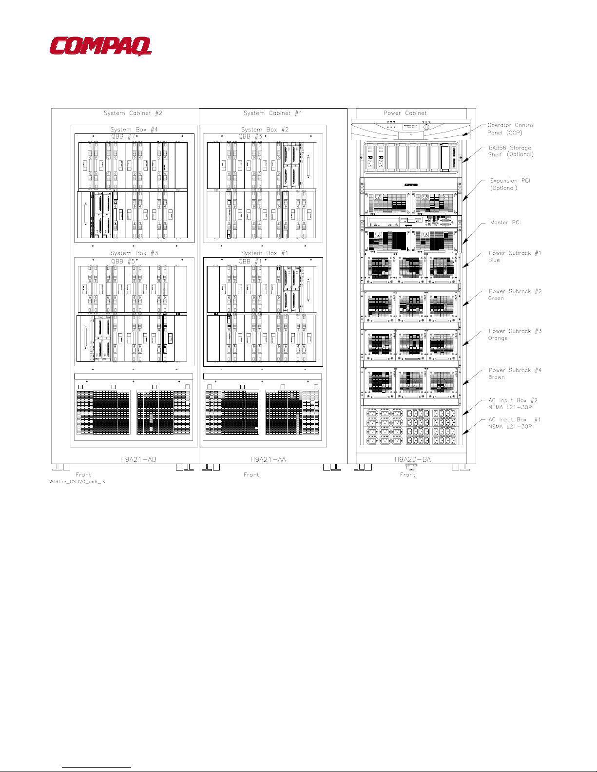
1.0 Compaq AlphaServer GS320 System Cabinet
Figure 1 Compaq AlphaServer GS320 System Front View
Note
: The picture above depicts a fully configured GS320 with 32 CPUs and 256GB of memory. Additional
Expander cabinets may be added to increase I/O.
6
Page 7

1.0 Compaq AlphaServer GS320 system (continued)
Figure 2 Compaq AlphaServer 320 System Rear View
7
Page 8
2.0 System Cabinet #1 Layout
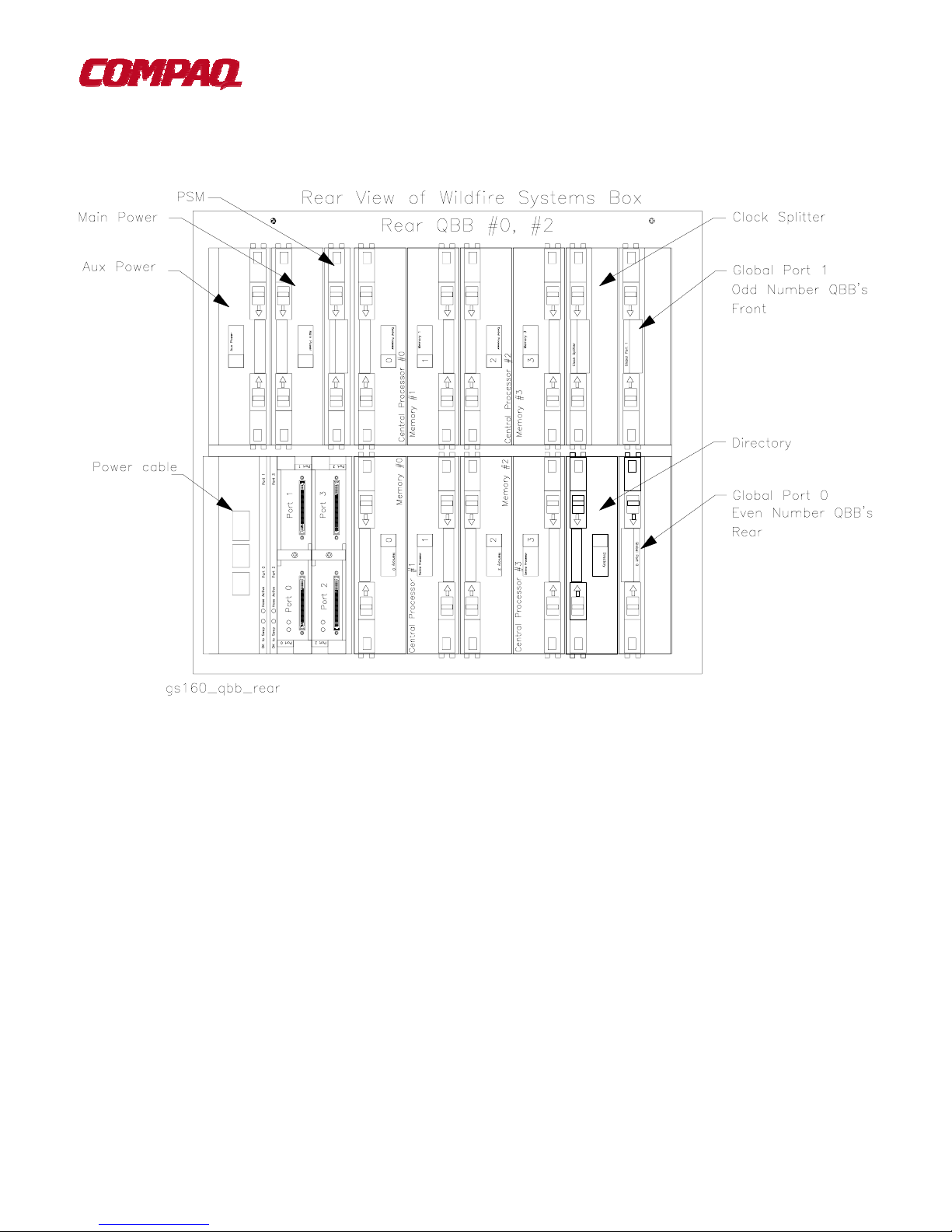
2.1 System Cabinet #1, System Box Rear Layout (QBB #0, QBB #2)
Figure 3 System Cabinet #1 Quad Building Blocks (QBB #0, QBB #2)
8
Page 9

2.2 System Cabinet #1, System Box Front Layout (QBB #1, QBB #3)
Figure 4 System Cabinet #1 Quad Building Blocks (QBB #1, QBB #3)
9
Page 10

3.0 System Cabinet #2 Layout
3.1 System Cabinet #2, System Box Rear Layout (QBB #4, QBB #6)
Figure 5 System Cabinet #2 Quad Building Blocks (QBB #4, QBB #6)
10
Page 11

3.2 System Cabinet #2, System Box Front Layout (QBB #5, QBB #7)
Figure 6 System Cabinet #2 Quad Building Blocks (QBB #5, QBB #7)
11
Page 12

4.0 Power Cabi net Layout
4.1 Operator Control Panel
Figure 7 Wildfire Operator Control Panel
The control panel is located at the top of the power cabinet. Shown above are the OCP’s three position On/Off
switch, three pushbuttons, three status LEDs, and an ASCII/graphical display.
12
Page 13

4.2 PCI Bus Master
4.2.1 PCI Slot Configuration Guidelines
! I/O riser 0 must be installed.
! The standard I/O module is always installed in riser 0-slot 1.
! Install high-powered modules in slots with one inch module pitch (all slots
6, riser 1-slot 5, and riser 1-slot 6).
! Install high-performance adapters across multiple bus/hose segments to get maximum performance
! VGA graphics options must be installed in riser 0-slot 2 or riser 0-slot 3.
CAUTION:
standard I/O module.
Installing a full-length module next to the standard I/O module requires extra care due to cabling on the
Figure 8 Master PCI Expansion Box
except
riser 0-slot 5, riser 0-slot
13
Page 14

4.3 Compaq AlphaServer GS320 Powered Subrack
Figure 9 Compaq AlphaServer GS320 Powered Subrack
The power subrack holds three power supplies that power a system box containing two QBBs.
14
Page 15

4.3.1.1 Power Supply Installation Or der
Loads must be properly distributed across the three phases to avoid nuisance tripping of circuit breakers. Therefore,
placement of the third, redundant power supply is important. Figure 12 provides a chart showing the recommended
placement.
Two power supplies are needed to power one system box, the H-switch, OCP, and blower. The third power supply
is redundant. When three power supplies are in a subrack, one may be hot swapped.
Figure 10 Power Supply Installation Order
15
Page 16

4.4 AC Input Box (Three Phase)
Figure 11 AC Input Box
Note:
Table 1 AC Input Box Circuit Breaker Line Protection
Two AC Input Boxes are required for the AlphaServer GS320.
Circuit
Breaker
CB1 30 All
CB2 15 J1
CB3 15 J2
CB4 15 J3
CB5 15 J4
CB6 15 J5
CB7 15 J6
CB8 15 J7-J10
CB9 15 J11-J14
CB10 15 J15-J18
CB11 15 J19-J22
Rating
Amps
Outlets Protected
16
Page 17

5.0 Field Replaceable Units Part Numbers
5.1.1 Quad Building Block System Box Field Replaceable Units
Table 2 QBB Field Replaceable Units (FRU) List
CPU Modules
Part Number Description
B4125-AA CPU Carrier Case
3X-KN8AA-AD
Memory (Main Memory and Directory Memory)
B4150-AA Memory module DIMM carrier
3X-MS8AA-BB
AlphaServer GS160/320 SMP Central Processor, 6/731-MHz with 4-MB On-board Cache,
True64 Unix
54-24941-xx 1-GB GS80/160/320 base memory module 256MB Mono 200Pin Sync DIMM
100MHz CL2 R (Qty: 4)
3X-MS8AA-CB
3X-MS8AA-DB
B4140-xx Directory module DIMM carrier
54-25023-Bx Directory DIMM type 128 Mbit type 2
54-25023-Cx Directory DIMM type 256 Mbit type 3
54-25023-Dx Directory DIMM type 256 Mbit type 4
QBB Modules
B4170-xx Local I/O riser
B4180-BB Global port interface module to hierarchical switch w/coax ribbon cable connectors(mictor) Rear
B4181-xx Global port interface module to hierarchical switch w/coax ribbon cable connectors(mictor) Front
54-25017-01 Main power converter (H7508-AA)
54-25123-01 Auxiliary power converter (H7509-AA)
54-25074-01 Power system manager
54-25117-02
54-24941-xx 2-GB GS80/160/320 base memory module 512MB Mono 200Pin Sync DIMM
100MHz CL2 R (Qty: 4)
54-25070-xx 4-GB GS80/160/320 base memory module 1GB Stacked 200Pin Sync DIMM
100MHz CL2 (Qty: 4)
Divides clock signal from global ref clkock module into 48 copies. The 48 copies are used to
drive the master phase locked loops.
17
Page 18

5.1.2 Field Replaceable Units Part Numbers
Console Serial Bus Modules
54-25125-01 CSB node ID module (PCI)
54-25355-01 H-switch CSB interface
54-25371-01 System cabinet CSB interface
12-45925-01 Connector, adapter, 2RJ45 (power cab frame)
12-45926-01 Connector, terminator, molded, 8 pos,
PCI Modules (excluding power)
B4190-xx Standard I/O module
54-25127-01 Standard I/O cable interface module
B4171-xx Remote I/O riser (a.k.a. PCI riser)
54-25125-01 CSB node ID module (PCI)
3R-A0284-xx CD-ROM
RX23L-xx 3.5” 1.4 MB floppy drive
30-55981-06 SCSI 9 GB disk (for factory-installed software)
54-25027-01 PCI backplane
H-switch, Clock Generation Modules, and Distribution Board
BA53A-xx H-switch upgrade
54-25115-01 H-switch power system manager (HPM)
54-30194-01 H-switch power converter, multi-output (H7511)
30-56061-01 H-switch clock module
54-25355-01 H-switch CSB interface
54-25371-01 CSB interface in both distribution board housing and GS80 drawer
30-56060-01 Dual output clock module (not in H-switch housing but in distribution board housing)
B4186-xx QBB distribution board (a.k.a. scrambler)
70-40112-01 QBB distribution board housing and assembly
18
Page 19

5.1.2 Field Replaceable Units Part Number (continued)
Drawer Modules Descriptions
B4172-xx Drawer riser
B4173-xx Drawer riser interface
BA185-xx Drawer distribution panel (a.k.a. scrambler)
54-30354-01 Drawer backplane (used to be 54-25047-01)
54-25371-01 Drawer CSB module
Power
70-33328-02 1000 watt power subrack, IEC power cord (GS80)
70-33328-03 1000 watt power subrack, NEMA power cord (GS80)
70-33328-01 1600 watt power subrack (GS160 & GS320)
30-48101-01 1600 watt power converter, 48V output (H7506-AA)
30-48466-01 425 watt power converter, multi-output, PCI (H7507-AA)
30-48100-01 1000 watt bulk power converter, 48V output (H7510-AA)
30-48847-01 GS80 U.S. AC input box (H7282-AA)
30-48205-04 GS80 European AC input box (H7282-AB)
30-48205-03 GS80 Japanese AC input box (H7282-AC)
30-48848-01 GS160/320 U.S./Japan AC input box (H7283-AA)
30-48848-02 GS160/320 European AC input box (H7283-AB)
Miscellaneous
70-33559-01 OCP assembly
54-30058-01 Short-circuit protection module (goes on most system mods.)
54-30394-01 Short-circuit protection module goes on remote I/O riser
BA51A-xx System box (a.k.a. firebox)
BA54A-BA PCI box without standard I/O module
90-00022-07 Foot level
Fans
12-23609-26 PCI fan
12-45727-01 Fan on drawer
12-47545-01 Blower (used in system cabinets 1 and 2)
19
Page 20

5.1.3 Field Replaceable Cables
Cable Description From To
17-00083-03
17-00442-18
17-04009-02 Adapter cable 50 to68 pin SCSI signal cable CD-ROM
17-04541-02 Coax clock cable Clock modules. Clock splitters
17-04563-0x I/O hose cable Local I/O riser Remote I/O riser
–01 expndr cab
–02 sys. box
–04 drawer
17-04709-01 Harness assembly Power subrack Pwr cab bulkhead
17-04710-01 Ribbon cable H-switch clock H-switch
17-04711-01 Power harness Power cab bulkhead Rear QBBs in sys cab 1
17-04711-02 Power harness Power cab bulkhead Rear QBBs in sys cab 2
17-04712-01 50 pin sig cable Power subrack Pwr cab bulkhead
17-04713-01 50 pin sig cable Power cab bulkhead Front QBBs in sys cab 1
17-04713-02 50 pin sig cable Power cab bulkhead Front QBBs in sys cab 2
17-04714-01 Power cable Power subrack Pwr cab bulkhead
17-04715-01 Power cable Power cab bulkhead blower
17-04715-02 Power cable Power cab bulkhead blower
17-04716-01 Power (48V/Vaux) QBB H-switch
17-04716-02 –01 long –02 short
17-04722-01 Power (48V/Vaux) QBB (8-P sys only) Dual output clock& CSB
17-04736-01
17-04797-01 Signal cable Standard I/O SCSI disk
17-04798-01 Power cable PCI backplane SCSI disk, floppy, CD-ROM
Power cord (GS80) in North
America)
Power cord (all GS160/320 +
GS80) in Europe/Japan
Signal cable CSB node ID mod CSB
AC input box PCI or storage device
AC input box PCI or storage device
CSB adapter CSB in H-switch
adapter
or distrib board housing
17-04800-01 Signal cable PCI backplane CSB ID module
17-04801-01 Signal cable Standard I/O Std I/O interface
17-04810-01 Signal cable PCI backplane OCP
17-04811-01 Power cable Power subrack(s) OCP
17-04844-01 Power cable Power subrack (dr) Drawer blower
17-04845-01 Power cable Power subrack (dr) Drawer bulkhead
17-04846-01 Power harness Power subrack (dr) Drawer bulkhead
17-04847-01 Ribbon cable Drawer backplane CSB module
17-04847-02 Ribbon cable Drawer backplane CSB module
17-04847-03 Ribbon cable Distrib. board CSB module
17-04847-04 Ribbon cable H-switch H-switch CSB mod.
17-04848-01 Signal cable Power subrack (dr) Drawer
17-04848-02 Signal cable Power subrack (dr) Drawer (upgrade)
17-04849-01 Signal cable Standard I/O Floppy
17-04850-01 Power cable Drawer bulkhead Front of backplane
17-04932-01 Signal cable Standard I/O CD-ROM
17-04936-01 Signal cable CSB adapter CSB adapter
17-04982-01 Power cable H-switch CSB module in
20
Page 21

5.1.3 Field Replaceable Cables (continued)
Cable Description From To
H-switch
17-04991-01 Ground strap This cable is used in several locations to electrically ground
cabinets, QBB backplanes, the H-switch, and distribution
board housing.
17-05011-01 Signal cable Global ports H-switch/distribution board
17-05023-01 Ground cable (12 meters) System cabinet x Stand-alone expander cabinet
21
Page 22

6.0 Compaq AlphaServer Foot Print and Cutout Information
6.1 Compaq AlphaServer GS320
Figure 12 Compaq AlphaServer GS320 Foot Print
22
Page 23

7.0 Compaq
AlphaServer
GS320 Environmental Information
7.1 Compaq AlphaServer GS320 Physical Information
GS320 enclosure System Dimensions
Width 2000 mm (78.7 in)
Depth 1000 mm (39.4 in)
Height 1700 mm (66.9 in.)
Weight 850 kg (1870 lb)
Expander Cabinet
Width 600 mm (23.6 in)
Depth 1000 mm (39.4 in)
Height 1700 mm (66.9 in)
Weight 613 kg (1349 lb)
Note:
The GS320 system is comprised of one H9A21-AA and one H9A21-AB cabinet bolted together with a width
of 55”. The Power cabinet H9A20-BA has a width of 23.5”.
23
Page 24

7.2 Compaq AlphaServer GS320 Power Requirements
Power Spec U.S./Canada Japan Europe
Voltage, Vrms
120/208 200 380/415
Frequence, Hz
Phase
Power Plug, Quantity
Phase current, Arms
Maximum input
current/phase, Arms
Total VA
Total power, watts
50-60 50-60 50-60
3∅ 3∅ 3∅
L21-30P, 2 (GS320) L21-30P, 2 (GS320) IEC309 5P 32A, 2 (GS320)
1 sys box: 17 1 sys box: 18 1 sys box: 10
2 sys boxes: 19 2 sys boxes: 20 2 sys boxes: 15
3 sys boxes: 19 3 sys boxes: 20 3 sys boxes: 13
4 sys boxes: 23 4 sys boxes: 24 4 sys boxes: 15
24 24 17
1 sys box: 4700 1 sys box: 4700 1 sys box: 4700
2 sys boxes: 7050 2 sys boxes: 7050 2 sys boxes: 7050
3 sys boxes: 9850 3 sys boxes: 9850 3 sys boxes: 9850
4 sys boxes: 12,200 4 sys boxes: 12,200 4 sys boxes: 12,200
1 sys box: 4650 1 sys box: 4650 1 sys box: 4650
2 sys boxes: 7000 2 sys boxes: 7000 2 sys boxes: 7000
3 sys boxes: 9750 3 sys boxes: 9750 3 sys boxes: 9750
4 sys boxes: 12,100 4 sys boxes: 12,100 4 sys boxes: 12,100
Heat output, Btu/hr
1 sys box: 15,900 1 sys box: 15,900 1 sys box: 15,900
2 sys boxes: 23,900 2 sys boxes: 23,900 2 sys boxes: 23,900
3 sys boxes: 33,900 3 sys boxes: 33,900 3 sys boxes: 33,900
4 sys boxes: 41,300 4 sys boxes: 41,300 4 sys boxes: 41,300
24
Page 25

7.3 Power Specification of I/O Expansion Cabinet
Power Spec U.S./Canada Japan Europe
Voltage, Vrms
120 200 220/240
Frequence, Hz
Phase
Power Plug, Quantity
Phase current, Arms
Total VA
Total power, watts
Heat output, Btu/hr
50-60 50-60 50-60
1∅ 1∅ 1∅
L5-30P, 2 L6-30P, 1 IEC309 3P 32A, 1
22 24 22
4,800 4,800 4,800
4,750 4,750 4,750
16,200 16,200 16,200
7.4 Compaq AlphaServer GS320 Environmental Specifications
Variable Specifications
Temperature
Operating
Non-operating (storage)
5° to 35° C (41 to 95° F)
-40 to 66° C (-40 to 151° F)
Relative humidity (non-condensing)
Operating 10 to 90%
Non-operating (storage) 10 to 95%
Maximum altitude
Operating 3050m (10,000ft)
Non-operating (storage) 12,200m (40,000ft)
Minimum Clearances
Front operating 75 cm (29.5 in)
Front Service 75 cm (29.5 in)
Rear Operating 15 cm (6.0 in)
Rear Service 75 cm (29.5 in)
Left side operating none
Left side service 75 cm (29.5 in)
Right side operating none
Right side service none
25
Page 26

8.0 Compaq Recommended Specifications Operating Environment
The specifications presented are recommended by Compaq / Digital to optimize the
operating environment for your computer hardware.
8.1 Voltage
Nominal: Single-phase products: 120 Volts
Three-phase products: 208Y/120 Volts
Range: Single-phase products: 104 - 128 Volts
Three-phase products: 180 - 220 Volts
Crest Factor: 1.4 + 1%
8.2 Voltage Unbalance
Equipment requiring 3-phase power shall operate satisfactorily when the voltage unbalance is 5% or less as
calculated below.
(V
- V
max
Unbalance percent = ------------------------------
(V
min
avg
) x 100
)
Where; V
= maximum line-to-line RMS voltage
max
V
= minimum line-to-line RMS voltage
min
(VAB + VBC + VCA)
V
= ----------------------------
avg
3
VAB, VBC, VCA = line-to-line voltage
8.3 Voltage Transients
Power line transients should be no greater in amplitude than the value of the nominal AC RMS voltage. This
limitation applies to common and transverse mode transients of positive or negative polarity as they are imposed in
the AC sine wave.
8.4 Voltage Harmonic Distortion
The power source voltage total harmonic distortion should not exceed 5% with any single harmonic not exceeding
3% of the fundamental frequency.
8.5 Frequency
Nominal: 60 Hz
Range: 59 - 61 Hz
8.6 Phase Angle Unbalance
Maximum of 5o variation from the 120o relationship for 3-phase power.
8.7 Phase Rotation
ABC
26
Page 27

8.8 Current Unbalance
Equipment requiring 3-phase power shall operate satisfactorily when the current unbalance is a maximum of 5
amps or 20% as calculated below.
(I
Unbalance percent = --------------------------
(I
Where; I
- I
max
max
I
min
(IA + IB + IC)
I
avg
3
IA, IB, IC = line currents in RMS amperes
) x 100
min
)
avg
= maximum line currents in RMS amperes
= minimum line currents in RMS amperes
= --------------------
8.9 Magnetic Fields
Most equipment, excluding monitors and some disk and tape products at power line frequencies, can operate
properly up to the AC magnetic field flux density limits specified below. Above these limits, the operation of some
equipment may be impaired.
Frequency (Hertz) Maximum field (Gauss)
50 10.0
500 2.0
1000 1.0
10000 0.1
500000 0.002
For high resolution monitors using refresh rates different from the power line frequency, the maximum AC magnetic
field flux density at power line frequencies is 7.07 mGauss RMS (20 mGauss peak-to-peak). For low resolution
monitors, the maximum AC magnetic field flux density at power line frequencies varies with the product, but is
always greater than 7.07 mGauss RMS. The maximum DC magnetic field flux density limit up to which most
monitors operate properly is approximately 2.0 Gauss.
For some disk and tape drive products, the maximum Dc and AC magnetic field flux density specified at power line
frequencies is 3.0 Gauss. Other disk and tape drive products can withstand higher magnetic field flux densities
Avoid storage of media in Ac or DC magnetic fields. In unavoidable locations, the media should only be subjected
to AC magnetic field flux densities up to a maximum of 3.0 Gauss.
8.10 Electric Fields
Maximum of 2 volts/meter cumulative total for radiated fields from 10 kHz to 1 GHz.
Ensure that not more than 1 volt RMS is present on the AC connection points to the computer system from 10 kHz
to 30 MHz. Measure between frame of the equipment and all phase, neutral, and grounding connections at the
power receptacle(s).
27
Page 28

8.11 Operating Environment
Temperature range: 21oC +3oC (70oF+5oF)
Temperature rate of change: Maximum of 3oC/hour (5.4oF/hour)
Temperature adjustment for altitude: Reduce the operating temperature by 1.8oC/1000 meters (1oF/1000
feet)
Relative humidity range: 50% RH+10% (no condensation)
Relative humidity rate of change: Maximum of 6%/hour
8.12 Shipping And Storage In Shipment Containers For Less Than 60 Days
Temperature range: -40o to 66oC (-40o to 151oF)
Temperature rate of change: Maximum of 20oC/hour (36oF/hour)
Relative humidity range: 0 to 95% RH (no condensation)
8.13 Storage In Shipment Containers For More Than 60 Days
Temperature range: 5o to 50oC (40o to 122oF)
Temperature rate of change: Maximum of 11oC/hour (20oF/hour)
Relative humidity range: 10 to 95% RH (no condensation)
Wet bulb temperature: Maximum of 32oC (90oF)
8.14 Altitude
Most equipment has been normally tested on a short-term basis for performance, up to an altitude of 2.4 kilometers
(8000 feet). Above this altitude, the operation of equipment may be impaired.
8.15 Airflow Rate Range
266-314 m3/h-kilowatts or 550-650 cfm/ton at the air-conditioner output
8.16 Vibration
Most equipment has been normally tested on a short-term basis for performance up to the vibration limits specified
below. Above these limits or with a continuous vibration level, the operation of equipment may be impaired
Frequency (Hertz) Amplitude
5 - 22 0.254 millimeters (0.010 inches) double amplitude
22-500 0.25 g peak
28
Page 29

9.0 Reference Documentation
Table 3 AlphaServer GS160/320 Documentation
Order Number Title
QA–6GAAA–G8 AlphaServer GS80/160/320 Documentation Kit
EK–GS320–UG
EK–GSCON–IN
EK–GS320–RM
EK–GS320–IN
EK–GSR80–IN
AG–RKSWA–BE AlphaServer GS80/160/320 User Information CD (HTML files)
AG–RLVJA–BE AlphaServer GS80/160/320 User Information CD (translations)
QA–6GAAB–G8 AlphaServer GS80/160/320 Service Documentation Kit
EK–GS320–SV
AG–RKSZA–BE AlphaServer GS80/160/320 Service Information CD
EK–GS320–UP
EK–GSR80–UP
EK–GS320–QR
EK–GS320–SP
AlphaServer GS80/160/320 User’s Guide
AlphaServer GS80/160/320 System Management Console Installation and User’ s Guide
AlphaServer GS80/160/320 Firmware Reference Manual
AlphaServer GS160/320 Installation Guide
AlphaServer GS80 Installation Guide
AlphaServer GS80/160/320 Service Manual
AlphaServer GS160/320 Upgrade Manual
AlphaServer GS80 Upgrade Manual
AlphaServer GS80/160/320 Quick Reference
AlphaServer GS80/160/320 Site Preparation
29
 Loading...