

Page 1

TruCluster Server
Hardware Configuration
Part Number: AA-RHGWB-TE
April 2000
Product Version: TruCluster Server Version 5.0A
Operating System and Version: Tru64 UNIX Version 5.0A
This manual describes how to configure the hardware for a TruCluster
Server environment. TruCluster Server Version 5.0A runs on the Tru64™
®
UNIX
operating system.
Compaq Computer Corporation
Houston, Texas
Page 2

© 2000 Compaq Computer Corporation
COMPAQandthe Compaq logo Registered in U.S. Patent and Trademark Office. TruCluster and Tru64 are
trademarks of Compaq Information Technologies Group, L.P.
Microsoft and Windows are trademarks of Microsoft Corporation. UNIX and The Open Group are
trademarks of The Open Group. All other product names mentioned herein may be trademarks or
registered trademarks of their respective companies.
Confidential computer software. Valid license from Compaq required for possession, use, or copying.
Consistent with FAR 12.211 and 12.212, Commercial Computer Software, Computer Software
Documentation, and Technical Data for Commercial Items are licensed to the U.S. Government under
vendor’s standard commercial license.
Compaq shall not be liable for technical or editorial errors or omissions contained herein. The information
in this publication is subject to change without notice and is provided "as is" without warranty of any
kind. The entire risk arising out of the use of this information remains with recipient. In no event shall
Compaq be liable for any direct, consequential, incidental, special, punitive, or other damages whatsoever
(including without limitation, damages for loss of business profits, business interruption or loss of business
information), even if Compaq has been advised of the possibility of such damages. The foregoing shall
apply regardless of the negligence or other fault of either party and regardless of whether such liability
sounds in contract, negligence, tort, or any other theory of legal liability, and notwithstanding any failure of
essential purpose of any limited remedy.
The limited warranties for Compaq products are exclusively set forth in the documentation accompanying
such products. Nothing herein should be construed as constituting a further or additional warranty.
Page 3

About This Manual
1 Introduction
1.1
1.2
1.3
1.4
1.4.1
1.4.1.1
1.4.1.2
1.4.1.3
1.4.1.4
1.5
1.6
1.6.1
1.6.2
1.6.3
1.6.4
1.6.5
1.7
The TruCluster Server Product ..................................... 1–1
Overview of the TruCluster Server Hardware Configuration .. 1–2
Memory Requirements ...............................................
Minimum Disk Requirements ...................................... 1–3
Disks Needed for Installation .................................. 1–3
Tru64 UNIX Operating System Disk ..................... 1–3
Clusterwide Disk(s) ......................................... 1–4
Member Boot Disk .......................................... 1–4
Quorum Disk .................................................
Generic Two-NodeCluster ........................................... 1–5
Growing a Cluster from Minimum Storage to a NSPOF
Cluster ..................................................................
Two-Node Clusters Using an UltraSCSI BA356 Storage
Shelf and Minimum Disk Configurations .................... 1–8
Two-Node Clusters Using UltraSCSI BA356 Storage Units
with Increased Disk Configurations .......................... 1–10
Two-Node Configurations with UltraSCSI BA356 Storage
Units and Dual SCSI Buses .................................... 1–12
Using Hardware RAID to Mirror the Clusterwide Root
File System and Member System Boot Disks ................ 1–13
Creating a NSPOF Cluster ..................................... 1–15
Overview of Setting up the TruCluster Server Hardware
Configuration .......................................................... 1–17
Contents
1–3
1–5
1–7
2 Hardware Requirements and Restrictions
2.1
2.2
2.3
2.4
2.4.1
2.4.2
2.5
TruCluster Server Member System Requirements .............. 2–1
Memory Channel Restrictions ...................................... 2–1
Fibre Channel Requirements and Restrictions .................. 2–3
SCSI Bus Adapter Restrictions ..................................... 2–6
KZPSA-BB SCSI Adapter Restrictions ....................... 2–6
KZPBA-CB SCSI Bus Adapter Restrictions ................. 2–6
Disk Device Restrictions ............................................. 2–7
Contents iii
Page 4

2.6
2.7
2.8
2.9
2.10
RAID Array Controller Restrictions ...............................
SCSI Signal Converters ..............................................
DS-DWZZH-03 and DS-DWZZH-05 UltraSCSI Hubs ........... 2–9
SCSI Cables ............................................................
SCSI Terminators and Trilink Connectors ........................ 2–11
3 Shared SCSI Bus Requirements and Configurations Using
UltraSCSI Hardware
3.1
3.2
3.2.1
3.2.2
3.2.3
3.2.4
3.3
3.4
3.5
3.6
3.6.1
3.6.1.1
3.6.1.2
3.6.1.2.1
3.6.1.2.2
3.6.1.2.3
3.6.1.2.4
3.6.1.2.5
3.6.1.3
3.7
3.7.1
3.7.1.1
3.7.1.2
Shared SCSI Bus Configuration Requirements .................. 3–2
SCSI Bus Performance ...............................................
SCSI Bus Versus SCSI Bus Segments ........................ 3–4
Transmission Methods .......................................... 3–4
Data Path .........................................................
Bus Speed .........................................................
SCSI Bus Device Identification Numbers ........................ 3–5
SCSI Bus Length ......................................................
Terminating the Shared SCSI Bus when Using UltraSCSI
Hubs ....................................................................
UltraSCSI Hubs .......................................................
Using a DWZZH UltraSCSI Hub in a Cluster
Configuration .....................................................
DS-DWZZH-03 Description ................................ 3–9
DS-DWZZH-05 Description ................................ 3–10
DS-DWZZH-05 Configuration Guidelines .......... 3–10
DS-DWZZH-05 Fair Arbitration ..................... 3–12
DS-DWZZH-05 Address Configurations ............ 3–13
SCSI Bus Termination Power ......................... 3–15
DS-DWZZH-05 Indicators ............................. 3–15
Installing the DS-DWZZH-05 UltraSCSI Hub .......... 3–15
Preparing the UltraSCSI Storage Configuration ................ 3–16
Configuring Radially Connected TruCluster Server
Clusters with UltraSCSI Hardware ........................... 3–17
Preparing an HSZ70 or HSZ80 for a Shared SCSI Bus
Using Transparent Failover Mode ........................ 3–18
Preparing a Dual-Redundant HSZ70 or HSZ80 for a
Shared SCSI Bus Using Multiple-Bus Failover ........ 3–22
2–7
2–8
2–9
3–3
3–5
3–5
3–6
3–7
3–8
3–9
4 TruCluster Server System Configuration Using UltraSCSI
Hardware
4.1
4.2
iv Contents
Planning Your TruCluster Server Hardware Configuration ... 4–2
Obtaining the Firmware Release Notes ........................... 4–4
Page 5

4.3
4.3.1
4.3.2
4.3.3
4.3.3.1
4.3.3.2
4.3.3.3
TruCluster Server Hardware Installation ........................ 4–5
Installation of a KZPBA-CB Using Internal Termination
for a Radial Configuration ......................................
Displaying KZPBA-CB Adapters with the show Console
Commands ........................................................
Displaying Console Environment Variables and Setting
the KZPBA-CB SCSI ID ........................................ 4–14
Displaying KZPBA-CB pk* or isp* Console
Environment Variables ..................................... 4–15
Setting the KZPBA-CB SCSI ID .......................... 4–17
KZPBA-CB Termination Resistors ........................ 4–17
5 Setting Up the Memory Channel Cluster Interconnect
5.1
5.1.1
5.1.2
5.2
5.3
5.4
5.5
5.5.1
5.5.1.1
5.5.1.2
5.5.2
5.5.2.1
5.5.2.2
5.5.2.3
5.5.2.4
5.6
Setting the Memory Channel Adapter Jumpers ................ 5–2
MC1 and MC1.5 Jumpers ....................................... 5–2
MC2 Jumpers .....................................................
Installing the Memory Channel Adapter .......................... 5–5
Installing the MC2 Optical Converter in the Member System 5–6
Installing the Memory Channel Hub .............................. 5–6
Installing the Memory Channel Cables ........................... 5–7
Installing the MC1 or MC1.5 Cables .......................... 5–7
Connecting MC1 or MC1.5 Link Cables in Virtual Hub
Mode ...........................................................
Connecting MC1 Link Cables in Standard Hub Mode . 5–8
Installing the MC2 Cables ...................................... 5–9
Installing the MC2 Cables for Virtual Hub Mode
Without Optical Converters ............................... 5–9
Installing MC2 Cables in Virtual Hub Mode Using
Optical Converters .......................................... 5–10
Connecting MC2 Link Cables in Standard Hub Mode
(No Fiber Optics) ............................................ 5–10
Connecting MC2 Cables in Standard Hub Mode Using
Optical Converters .......................................... 5–10
Running Memory Channel Diagnostics ........................... 5–11
4–7
4–10
5–3
5–8
6 Using Fibre Channel Storage
6.1
6.2
6.2.1
6.2.2
6.2.2.1
Procedure for Installation Using Fibre Channel Disks ......... 6–2
Fibre Channel Overview ............................................. 6–4
Basic Fibre Channel Terminology ............................. 6–4
Fibre Channel Topologies ....................................... 6–5
Point-to-Point ................................................ 6–6
Contents v
Page 6

6.2.2.2
6.2.2.3
6.3
6.3.1
6.3.2
6.4
6.4.1
6.4.2
6.5
6.5.1
6.5.1.1
6.5.1.2
6.5.1.2.1
6.5.1.2.2
6.5.1.2.3
6.5.1.2.4
6.5.1.2.5
6.5.2
6.5.2.1
6.5.2.2
6.5.2.3
6.5.3
6.5.3.1
6.6
6.6.1
6.6.2
6.6.3
6.7
6.8
6.9
6.10
6.11
Fabric .........................................................
Arbitrated Loop Topology ..................................
6–6
6–7
Example Fibre Channel Configurations Supported by
TruCluster Server .....................................................
6–8
Fibre Channel Cluster Configurations for Transparent
Failover Mode .....................................................
6–8
Fibre Channel Cluster Configurations for Multiple-Bus
Failover Mode .....................................................
6–10
Zoning and Cascaded Switches ..................................... 6–13
Zoning ..............................................................
Cascaded Switches ...............................................
6–13
6–14
Installing and Configuring Fibre Channel Hardware ........... 6–15
Installing and Setting Up the Fibre Channel Switch ...... 6–15
Installing the Switch ........................................ 6–16
Managing the Fibre Channel Switches .................. 6–17
Using the Switch Front Panel ........................ 6–17
Setting the Ethernet IP Address and Subnet Mask
from the Front Panel ................................... 6–18
Setting the DS-DSGGB-AA Ethernet IP Address
and Subnet Mask from a PC or Terminal ........... 6–20
Logging Into the Switch with a TelnetConnection 6–20
Setting the Switch Name via TelnetSession ....... 6–21
Installing and Configuring the KGPSA PCI-to-Fibre
Channel Adapter Module ....................................... 6–22
Installing the KGPSA PCI-to-Fibre Channel Adapter
Module ........................................................
6–22
Setting the KGPSA-BC or KGPSA-CA to Run on a
Fabric ......................................................... 6–23
Obtaining the Worldwide Names of KGPSA Adapters 6–25
Setting up the HSG80 Array Controller for Tru64 UNIX
Installation ........................................................ 6–26
Obtaining the Worldwide Names of HSG80 Controller 6–31
Preparing to Install Tru64 UNIX and TruCluster Server on
Fibre Channel Storage ............................................... 6–33
Configuring the HSG80 Storagesets .......................... 6–33
Setting the Device Unit Number .............................. 6–40
Setting the bootdef_dev Console Environment Variable ... 6–46
Install the Base Operating System ................................ 6–48
Resetting the
bootdef_dev Console Environment Variable .. 6–49
Determining /dev/disk/dskn to Use for a Cluster Installation . 6–51
Installing the TruCluster Server Software ....................... 6–53
Changing the HSG80 from Transparent to Multiple-Bus
Failover Mode ......................................................... 6–54
vi Contents
Page 7

6.12
6.12.1
6.12.2
Using the emx Manager to Display Fibre Channel Adapter
Information ............................................................
Using the emxmgr Utility to Display Fibre Channel
Adapter Information .............................................
Using the emxmgr Utility Interactively ...................... 6–61
7 Preparing ATM Adapters
7.1
7.2
7.3
7.4
ATM Overview ........................................................
Installing ATM Adapters ............................................
Verifying ATM Fiber Optic Cable Connectivity .................. 7–4
ATMworks Adapter LEDs ........................................... 7–6
8 Configuring a Shared SCSI Bus for Tape Drive Use
8.1
8.1.1
8.1.2
8.1.3
8.1.4
8.2
8.2.1
8.2.2
8.2.3
8.2.4
8.3
8.3.1
8.3.2
8.4
8.4.1
8.4.2
8.5
8.5.1
8.5.2
8.6
8.6.1
8.6.2
8.7
8.7.1
8.7.2
Preparing the TZ88 for Shared Bus Usage ....................... 8–1
Setting the TZ88N-VA SCSI ID ............................... 8–2
Cabling the TZ88N-VA .......................................... 8–3
Setting the TZ88N-TA SCSI ID ............................... 8–4
Cabling the TZ88N-TA .......................................... 8–4
Preparing the TZ89 for Shared SCSI Usage ...................... 8–5
Setting the DS-TZ89N-VW SCSI ID .......................... 8–5
Cabling the DS-TZ89N-VW Tape Drives ..................... 8–7
Setting the DS-TZ89N-TA SCSI ID ........................... 8–8
Cabling the DS-TZ89N-TA Tape Drives ...................... 8–8
Compaq 20/40 GB DLT Tape Drive ................................ 8–9
Setting the Compaq 20/40 GB DLT Tape Drive SCSI ID .. 8–9
Cabling the Compaq 20/40 GB DLT Tape Drive ............. 8–10
Preparing the TZ885 for Shared SCSI Usage .................... 8–13
Setting the TZ885 SCSI ID .................................... 8–13
Cabling the TZ885 Tape Drive ................................ 8–13
Preparing the TZ887 for Shared SCSI Bus Usage ............... 8–15
Setting the TZ887 SCSI ID .................................... 8–15
Cabling the TZ887 Tape Drive ................................ 8–16
Preparing the TL891 and TL892 DLT MiniLibraries for
Shared SCSI Usage ................................................... 8–18
Setting the TL891 or TL892 SCSI ID ......................... 8–18
Cabling the TL891 or TL892 MiniLibraries ................. 8–20
Preparing the TL890 DLT MiniLibrary Expansion Unit ....... 8–23
TL890 DLT MiniLibrary Expansion Unit Hardware ....... 8–24
Preparing the DLT MiniLibraries for Shared SCSI Bus
Usage .............................................................. 8–24
6–59
6–59
7–1
7–3
Contents vii
Page 8

8.7.2.1
8.7.2.2
8.7.2.3
8.7.2.4
8.8
8.8.1
8.8.2
8.8.3
8.8.4
8.9
8.9.1
8.9.2
8.9.3
8.9.4
8.9.5
8.10
8.10.1
8.10.2
8.10.3
8.10.4
8.10.5
8.10.6
8.11
8.11.1
8.11.1.1
8.11.1.2
8.11.1.3
8.11.1.4
8.11.2
8.11.2.1
Cabling the DLT MiniLibraries ........................... 8–24
Configuring a Base Module as a Slave ................... 8–26
Powering Up the DLT MiniLibrary ....................... 8–28
Setting the TL890/TL891/TL892 SCSI ID ............... 8–28
Preparing the TL894 DLT Automated Tape Library for Shared
SCSI Bus Usage .......................................................
8–30
TL894 Robotic Controller Required Firmware .............. 8–30
Setting TL894 Robotics Controller and Tape Drive SCSI
IDs ..................................................................
8–30
TL894 Tape Library Internal Cabling ........................ 8–33
Connecting the TL894 Tape Library to the Shared SCSI
Bus .................................................................
8–34
Preparing the TL895 DLT Automated Tape Library for Shared
SCSI Bus Usage .......................................................
8–36
TL895 Robotic Controller Required Firmware .............. 8–37
Setting the TL895 Tape Library SCSI IDs ................... 8–37
TL895 Tape Library Internal Cabling ........................ 8–38
Upgrading a TL895 ..............................................
8–40
Connecting the TL895 Tape Library to the Shared SCSI
Bus .................................................................
8–40
Preparing the TL893 and TL896 Automated Tape Libraries
for Shared SCSI Bus Usage ......................................... 8–40
Communications with the Host Computer ................... 8–42
MUC Switch Functions ......................................... 8–42
Setting the MUC SCSI ID ...................................... 8–43
Tape Drive SCSI IDs ............................................
8–43
TL893 and TL896 Automated Tape Library Internal
Cabling ............................................................. 8–44
Connecting the TL893 and TL896 Automated Tape
Libraries to the Shared SCSI Bus ............................. 8–47
Preparing the TL881 and TL891 DLT MiniLibraries for
Shared Bus Usage .................................................... 8–48
TL881 and TL891 DLT MiniLibraries Overview ............ 8–48
TL881 and TL891 DLT MiniLibrary Tabletop Model .. 8–49
TL881 and TL891 MiniLibrary Rackmount
Components ................................................. 8–49
TL881 and TL891 Rackmount Scalability ............... 8–50
DLT MiniLibrary Part Numbers .......................... 8–51
Preparing a TL881 or TL891 MiniLibrary for Shared SCSI
Bus Use ............................................................ 8–52
Preparing a Tabletop Model or Base Unit for
Standalone Shared SCSI Bus Usage ..................... 8–52
viii Contents
Page 9

8.11.2.1.1
8.11.2.1.2
8.11.2.2
8.11.2.2.1
8.11.2.2.2
8.11.2.2.3
8.11.2.2.4
8.12
8.12.1
8.12.2
8.12.3
8.12.3.1
8.12.3.2
8.12.3.3
8.12.3.4
Compaq ESL9326D Enterprise Library ........................... 8–64
Setting the Standalone MiniLibrary Tape Drive
SCSI ID ..................................................
Cabling the TL881 or TL891 DLT MiniLibrary .... 8–54
Preparing a TL881 or TL891 Rackmount MiniLibrary
for Shared SCSI Bus Usage ................................
Cabling the Rackmount TL881 or TL891 DLT
MiniLibrary .............................................
Configuring a Base Unit as a Slave to the
Expansion Unit ......................................... 8–61
Powering Up the TL881/TL891 DLT MiniLibrary . 8–62
Setting the SCSI IDs for a Rackmount TL881 or
TL891 DLT MiniLibrary ............................... 8–63
General Overview ................................................
ESL9326D Enterprise Library Overview ..................... 8–65
Preparing the ESL9326D Enterprise Library for Shared
SCSI Bus Usage ..................................................
ESL9326D Enterprise Library Robotic and Tape Drive
Required Firmware ......................................... 8–66
Library Electronics and Tape Drive SCSI IDs .......... 8–66
ESL9326D Enterprise Library Internal Cabling ....... 8–66
Connecting the ESL9326D Enterprise Library to the
Shared SCSI Bus ............................................
8–53
8–58
8–58
8–64
8–65
8–68
9 Configurations Using External Termination or Radial Connections
to Non-UltraSCSI Devices
9.1
9.1.1
9.1.2
9.1.2.1
9.1.2.2
9.2
9.3
9.3.1
9.3.2
9.3.2.1
9.3.2.2
9.4
Using SCSI Bus Signal Converters ................................ 9–2
Types of SCSI Bus Signal Converters ......................... 9–2
Using the SCSI Bus Signal Converters ....................... 9–3
DWZZA and DWZZB Signal Converter Termination .. 9–3
DS-BA35X-DA Termination ............................... 9–4
Terminating the Shared SCSI Bus ................................. 9–5
Overview of Disk Storage Shelves .................................. 9–8
BA350 Storage Shelf ............................................. 9–9
BA356 Storage Shelf ............................................. 9–10
Non-UltraSCSI BA356 Storage Shelf .................... 9–10
UltraSCSI BA356 Storage Shelf .......................... 9–13
Preparing the Storage for Configurations Using External
Termination ............................................................ 9–14
Contents ix
Page 10

9.4.1
9.4.1.1
9.4.1.2
9.4.1.3
9.4.2
9.4.2.1
9.4.2.2
9.4.2.3
9.4.3
9.4.3.1
9.4.3.2
9.4.4
Preparing BA350, BA356, and UltraSCSI BA356 Storage
Shelves for an Externally Terminated TruCluster Server
Configuration .....................................................
Preparing a BA350 Storage Shelf for Shared SCSI
Usage ..........................................................
Preparing a BA356 Storage Shelf for Shared SCSI
Usage ..........................................................
Preparing an UltraSCSI BA356 Storage Shelf for a
TruCluster Configuration .................................. 9–17
Connecting Storage Shelves Together ........................ 9–17
Connecting a BA350 and a BA356 for Shared SCSI
Bus Usage ....................................................
Connecting Two BA356s for Shared SCSI Bus Usage . 9–20
Connecting Two UltraSCSI BA356s for Shared SCSI
Bus Usage ....................................................
Cabling a Non-UltraSCSI RAID Array Controller to an
Externally Terminated Shared SCSI Bus .................... 9–24
Cabling an HSZ40 or HSZ50 in a Cluster Using
External Termination ....................................... 9–25
Cabling an HSZ20 in a Cluster using External
Termination ..................................................
Cabling an HSZ40 or HSZ50 RAID Array Controller in a
Radial Configuration with an UltraSCSI Hub .............. 9–28
9–15
9–15
9–16
9–18
9–21
9–27
10 Configuring Systems for External Termination or Radial
Connections to Non-UltraSCSI Devices
10.1
10.1.1
10.1.2
10.1.3
10.1.4
10.1.4.1
10.1.4.2
10.1.4.3
10.1.4.4
x Contents
TruCluster Server Hardware Installation Using PCI SCSI
Adapters ................................................................ 10–1
Radial Installation of a KZPSA-BB or KZPBA-CB Using
Internal Termination ............................................ 10–2
Installing a KZPSA-BB or KZPBA-CB Using External
Termination ....................................................... 10–6
Displaying KZPSA-BB and KZPBA-CB Adapters with the
show Console Commands ....................................... 10–9
Displaying Console Environment Variables and Setting
the KZPSA-BB and KZPBA-CB SCSI ID ..................... 10–13
Displaying KZPSA-BB and KZPBA-CB pk* or isp*
Console Environment Variables ........................... 10–13
Setting the KZPBA-CB SCSI ID .......................... 10–16
Setting KZPSA-BB SCSI Bus ID, Bus Speed, and
Termination Power .......................................... 10–17
KZPSA-BB and KZPBA-CB Termination Resistors .... 10–18
Page 11

10.1.4.5
Updating the KZPSA-BB Adapter Firmware ........... 10–18
A Worldwide ID to Disk Name Conversion Table
Index
Examples
4–1
4–2
4–3
4–4
4–5
4–6
4–7
5–1
6–1
6–2
6–3
6–4
10–1
10–2
10–3
10–4
10–5
10–6
10–7
10–8
10–9
Displaying Configuration on an AlphaServer DS20 ............. 4–10
Displaying Devices on an AlphaServer DS20 .................... 4–12
Displaying Configuration on an AlphaServer 8200 .............. 4–13
Displaying Devices on an AlphaServer 8200 ..................... 4–13
Displaying the pk* Console Environment Variables on an
AlphaServer DS20 System .......................................... 4–15
Displaying Console Variables for a KZPBA-CB on an
AlphaServer 8x00 System ........................................... 4–16
Setting the KZPBA-CB SCSI Bus ID .............................. 4–17
Running the mc_cable Test .......................................... 5–13
Determine HSG80 Connection Names ............................ 6–29
Setting up the Mirrorset .............................................
Using the wwidmgr quickset Command to Set Device Unit
Number .................................................................
Sample Fibre Channel Device Names ............................. 6–45
Displaying Configuration on an AlphaServer 4100 .............. 10–9
Displaying Devices on an AlphaServer 4100 ..................... 10–10
Displaying Configuration on an AlphaServer 8200 .............. 10–11
Displaying Devices on an AlphaServer 8200 ..................... 10–12
Displaying the pk* Console Environment Variables on an
AlphaServer 4100 System ........................................... 10–13
Displaying Console Variables for a KZPBA-CB on an
AlphaServer 8x00 System ........................................... 10–15
Displaying Console Variables for a KZPSA-BB on an
AlphaServer 8x00 System ........................................... 10–15
Setting the KZPBA-CB SCSI Bus ID .............................. 10–16
Setting KZPSA-BB SCSI Bus ID and Speed ...................... 10–17
6–34
6–43
Figures
1–1
Two-Node Cluster with Minimum Disk Configuration and No
Quorum Disk .......................................................... 1–6
Contents xi
Page 12

1–2
1–3
1–4
1–5
1–6
1–7
1–8
3–1
3–2
3–3
3–4
3–5
3–6
3–7
3–8
4–1
5–1
6–1
6–2
6–3
6–4
6–5
6–6
6–7
6–8
7–1
8–1
8–2
8–3
8–4
8–5
Generic Two-Node Cluster with Minimum Disk Configuration
and Quorum Disk .....................................................
1–7
Minimum Two-Node Cluster with UltraSCSI BA356 Storage
Unit .....................................................................
1–9
Two-Node Cluster with Two UltraSCSI DS-BA356 Storage
Units ....................................................................
1–11
Two-Node Configurations with UltraSCSI BA356 Storage
Units and Dual SCSI Buses ......................................... 1–13
Cluster Configuration with HSZ70 Controllers in Transparent
Failover Mode .........................................................
1–14
NSPOF Cluster using HSZ70s in Multiple-Bus Failover Mode 1–16
NSPOF Fibre Channel Cluster using HSG80s in Multiple-Bus
Failover Mode .........................................................
1–17
VHDCI Trilink Connector (H8861-AA) ............................ 3–8
DS-DWZZH-03 Front View .......................................... 3–10
DS-DWZZH-05 Rear View ........................................... 3–14
DS-DWZZH-05 Front View .......................................... 3–15
Shared SCSI Bus with HSZ70 Configured for Transparent
Failover .................................................................
3–20
Shared SCSI Bus with HSZ80 Configured for Transparent
Failover .................................................................
3–21
TruCluster Server Configuration with HSZ70 in Multiple-Bus
Failover Mode .........................................................
3–24
TruCluster Server Configuration with HSZ80 in Multiple-Bus
Failover Mode .........................................................
3–25
KZPBA-CB Termination Resistors ................................. 4–18
Connecting Memory Channel Adapters to Hubs ................. 5–9
Point-to-Point Topology .............................................. 6–6
Fabric Topology ........................................................ 6–7
Arbitrated Loop Topology ............................................ 6–8
Fibre Channel Single Switch Transparent Failover
Configuration ......................................................... 6–9
Multiple-Bus NSPOF Configuration Number 1 .................. 6–11
Multiple-Bus NSPOF Configuration Number 2 .................. 6–12
Multiple-Bus NSPOF Configuration Number 3 .................. 6–13
A Simple Zoned Configuration ...................................... 6–14
Emulated LAN Over an ATM Network ............................ 7–3
TZ88N-VA SCSI ID Switches ....................................... 8–2
Shared SCSI Buses with SBB Tape Drives ....................... 8–4
DS-TZ89N-VW SCSI ID Switches .................................. 8–6
Compaq 20/40 GB DLT Tape Drive Rear Panel .................. 8–10
Cabling a Shared SCSI Bus with a Compaq 20/40 GB DLT
Tape Drive ............................................................. 8–12
xii Contents
Page 13

8–6
8–7
8–8
8–9
8–10
8–11
8–12
8–13
8–14
8–15
8–16
8–17
8–18
8–19
9–1
9–2
9–3
9–4
9–5
9–6
9–7
9–8
9–9
9–10
9–11
9–12
9–13
9–14
9–15
10–1
Cabling a Shared SCSI Bus with a TZ885 .........
TZ887 DLT MiniLibrary Rear Panel ...............................
Cabling a Shared SCSI Bus with a TZ887 ........................ 8–17
TruCluster Server Cluster with a TL892 on Two Shared SCSI
Buses ....................................................................
TL890 and TL892 DLT MiniLibraries on Shared SCSI Buses . 8–26
TL894 Tape Library Four-Bus Configuration .................... 8–33
Shared SCSI Buses with TL894 in Two-Bus Mode .............. 8–35
TL895 Tape Library Internal Cabling ............................. 8–39
TL893 Three-Bus Configuration .................................... 8–45
TL896 Six-Bus Configuration ....................................... 8–46
Shared SCSI Buses with TL896 in Three-Bus Mode ............ 8–48
TL891 Standalone Cluster Configuration ......................... 8–57
TL881 DLT MiniLibrary Rackmount Configuration ............ 8–60
ESL9326D Internal Cabling ........................................ 8–67
Standalone SCSI Signal Converter ................................ 9–4
SBB SCSI Signal Converter ......................................... 9–4
DS-BA35X-DA Personality Module Switches .................... 9–5
BN21W-0B Y Cable ...................................................
HD68 Trilink Connector (H885-AA) ............................... 9–8
BA350 Internal SCSI Bus ........................................... 9–10
BA356 Internal SCSI Bus ........................................... 9–12
BA356 Jumper and Terminator Module Identification Pins ... 9–13
BA350 and BA356 Cabled for Shared SCSI Bus Usage ......... 9–19
Two BA356s Cabled for Shared SCSI Bus Usage ................ 9–21
Two UltraSCSI BA356s Cabled for Shared SCSI Bus Usage .. 9–23
Externally Terminated Shared SCSI Bus with Mid-Bus HSZ50
RAID Array Controllers ............................................. 9–26
Externally Terminated Shared SCSI Bus with HSZ50 RAID
Array Controllers at Bus End ....................................... 9–27
TruCluster Server Cluster Using DS-DWZZH-03, SCSI
Adapter with Terminators Installed, and HSZ50 ................ 9–30
TruCluster Server Cluster Using KZPSA-BB SCSI Adapters,
a DS-DWZZH-05 UltraSCSI Hub, and an HSZ50 RAID Array
Controller .............................................................. 9–31
KZPSA-BB Termination Resistors ................................. 10–18
............... 8–15
8–16
8–23
9–7
Tables
2–1
2–2
2–3
AlphaServer Systems Supported for Fibre Channel ............ 2–4
RAID Controller SCSI IDs .......................................... 2–7
Supported SCSI Cables .............................................. 2–10
Contents xiii
Page 14

2–4
3–1
3–2
3–3
3–4
4–1
4–2
4–3
5–1
5–2
5–3
6–1
6–2
7–1
8–1
8–2
8–3
8–4
8–5
8–6
8–7
8–8
8–9
8–10
8–11
8–12
8–13
8–14
9–1
9–2
9–3
Supported SCSI Terminators and Trilink Connectors .......... 2–11
SCSI Bus Speeds ......................................................
SCSI Bus Segment Length ..............
............................
3–5
3–7
DS-DWZZH UltraSCSI Hub Maximum Configurations ........ 3–11
Hardware Components Used in Configuration Shown in
Figure 3–5 Through Figure 3–8 ....................................
3–21
Planning Your Configuration ....................................... 4–3
Configuring TruCluster Server Hardware ........................ 4–6
Installing the KZPBA-CB for Radial Connection to a DWZZH
UltraSCSI Hub ........................................................
4–9
MC1 and MC1.5 Jumper Configuration ........................... 5–2
MC2 Jumper Configuration ......................................... 5–3
MC2 Linecard Jumper Configurations ............................ 5–5
Telnet Session Default User Names for Fibre Channel
Switches ................................................................
6–21
Converting Storageset Unit Numbers to Disk Names .......... 6–40
ATMworks Adapter LEDs ........................................... 7–6
TZ88N-VA Switch Settings .......................................... 8–3
DS-TZ89N-VW Switch Settings .................................... 8–6
Hardware Components Used to Create the Configuration
Shown in Figure 8 — 5 ...............................................
8–12
TL894 Default SCSI ID Settings ................................... 8–30
TL895 Default SCSI ID Settings ................................... 8–37
MUC Switch Functions ..............................................
MUC SCSI ID Selection .............................................
TL893 Default SCSI IDs .............................................
8–43
8–43
8–44
TL896 Default SCSI IDs ............................................. 8–44
TL881 and TL891 MiniLibrary Performance and Capacity
Comparison ............................................................ 8–51
DLT MiniLibrary Part Numbers ................................... 8–51
Hardware Components Used to Create the Configuration
Shown in Figure 8–17 ................................................ 8–57
Hardware Components Used to Create the Configuration
Shown in Figure 8–18 ................................................ 8–61
Shared SCSI Bus Cable and Terminator Connections for the
ESL9326D Enterprise Library ...................................... 8–68
Hardware Components Used for Configuration Shown in
Figure 8–9 and Figure 8–10 ......................................... 9–20
Hardware Components Used for Configuration Shown in
Figure 9–11 ............................................................ 9–24
Hardware Components Used for Configuration Shown in
Figure 8–12 and Figure 8–13 ....................................... 9–27
xiv Contents
Page 15

9–4
10–1
10–2
10–3
Hardware Components Used in Configuration Shown in
Figure 9–14 ............................................................
Configuring TruCluster Server Hardware for Use with a PCI
SCSI Adapter ..........................................................
Installing the KZPSA-BB or KZPBA-CB for Radial Connection
to a DWZZH UltraSCSI Hub ........................................
Installing a KZPSA-BB or KZPBA-CB for use with External
Termination ............................................................
9–30
10–2
10–4
10–7
A–1 Converting Storageset Unit Numbers to Disk Names .......... A–1
Contents xv
Page 16

Page 17

This manual describes how to set up and maintain the hardware
configuration for a TruCluster Server cluster.
Audience
This manual is for system administrators who will set up and configure the
hardware before installing the TruCluster Server software. The manual
assumes that you are familiar with the tools and methods needed to
maintain your hardware, operating system, and network.
Organization
This manual contains ten chapters and an index. The organization of this
manual has been restructured to provide a more streamlined manual.
Those chapters containing information on SCSI bus requirements and
configuration, and configuring hardware have been split up into two sets of
two chapters each. One set covers the UltraSCSI hardware and is geared
towards radial configurations. The other set covers configurations using
either external termination or radial connection to non-UltraSCSI devices.
A brief description of the contents follows:
About This Manual
Chapter 1 Introduces the TruCluster Server product and provides an overview
Chapter 2 Describes hardware requirements and restrictions.
Chapter 3 Contains information about setting up a shared SCSI bus, SCSI
Chapter 4 Describes how to prepare systems for a TruCluster Server
Chapter 5 Describes how to set up the Memory Channel cluster interconnect.
Chapter 6 Provides an overview of Fibre Channel and describes how
Chapter 7 Provides information on the use of, and installation of, Asynchronous
of setting up TruCluster Server hardware.
bus requirements, and how to connect storage to a shared SCSI
bus using the latest UltraSCSI products (DS-DWZZH UltraSCSI
hubs, HSZ70 and HSZ80 RAID array controllers).
configuration, and how to connect host bus adapters to shared
storage using the DS-DWZZH UltraSCSI hubs and the newest
RAID array controllers (HSZ70 and HSZ80).
to set up Fibre Channel hardware.
Transfer Mode (ATM) hardware.
About This Manual xvii
Page 18

Chapter 8 Describes how to configure a shared SCSI bus for tape drive,
tape loader, or tape library usage.
Chapter 9 Contains information about setting up a shared SCSI bus, SCSI bus
requirements, and how to connect storage to a shared SCSI bus using
external termination or radial connections to non-UltraSCSI devices.
Chapter 10
Describes how to prepare systems for a TruCluster Server configuration,
and how to connect host bus adapters to shared storage using external
termination or radial connection to non-UltraSCSI devices.
Related Documents
Users of the TruCluster Server product can consult the following manuals for
assistance in cluster installation, administration, and programming tasks:
• TruCluster Server Software Product Description (SPD) — The
comprehensive description of the TruCluster Server Version 5.0A
product. You can find the latest version of the SPD and other TruCluster
Server documentation at the following URL:
http://www.unix.digital.com/faqs/publications/pub_page/cluster_list.html
• Release Notes — Provides important information about TruCluster
Server Version 5.0A.
• Technical Overview — Provides an overview of the TruCluster Server
technology.
• Software Installation — Describes how to install the TruCluster Server
product.
• Cluster Administration — Describes cluster-specific administration
tasks.
• Highly Available Applications — Describes how to deploy applications on
a TruCluster Server cluster.
The UltraSCSI Configuration Guidelines document provides guidelines
regarding UltraSCSI configurations.
For information about setting up a RAID subsystem, see the following
documentation as appropriate for your configuration:
• DEC RAID Subsystem User’s Guide
• HS Family of Array Controllers User’s Guide
• RAID Array 310 Configuration and Maintenance Guide User’s Guide
• Configuring Your StorageWorks Subsystem HSZ40 Array Controllers
HSOF Version 3.0
• Getting Started RAID Array 450 V5.4 for Compaq Tru64 UNIX
Installation Guide
xviii About This Manual
Page 19

• HSZ70 Array Controller HSOF Version 7.0 Configuration Manual
• HSZ80 Array Controller ACS Version 8.2
• Compaq StorageWorks HSG80 Array Controller ACS Version 8.5
Configuration Guide
• Compaq StorageWorks HSG80 Array Controller ACS Version 8.5 CLI
Reference Guide
• Wwidmgr User’s Manual
For information about the tape devices, see the following documentation:
• TZ88 DLT Series Tape Drive Owner’s Manual
• TZ89 DLT Series Tape Drive User’s Guide
• TZ885 Model 100/200 GB DLT5-Cartridge MiniLibrary Owner’s Manual
• TZ887 Model 140/280 GB DLT7-Cartridge MiniLibrary Owner’s Manual
• TL881 MiniLibrary System User’s Guide
• TL881 MiniLibrary Drive Upgrade Procedure
• Pass-Through Expansion Kit Installation Instructions
• TL891 MiniLibrary System User’s Guide
• TL81X/TL894 Automated Tape Library for DLT Cartridges Facilities
Planning and Installation Guide
• TL81X/TL894 Automated Tape Library for DLT Cartridges Diagnostic
Software User’s Manual
• TL895 DLT Tape Library Facilities Planning and Installation Guide
• TL895 DLT Library Operator’s Guide
• TL895 DLT Tape Library Diagnostic Software User’s Manual
• TL895 Drive Upgrade Instructions
• TL82X/TL893/TL896 Automated Tape Library for DLT Cartridges
Facilities Planning and Installation Guide
• TL82X/TL893/TL896 Automated Tape Library for DLT Cartridges
Operator’s Guide
• TL82X/TL893/TL896 Automated Tape Library for DLT Cartridges
Diagnostic Software User’s Manual
• TL82X Cabinet-to-Cabinet Mounting Instructions
• TL82X/TL89X MUML to MUSL Upgrade Instructions
The Golden Eggs Visual Configuration Guide provides configuration
diagrams of workstations, servers, storage components, and clustered
About This Manual xix
Page 20

systems. It is available on line in PostScript and Portable Document Format
(PDF) formats at:
http://www.compaq.com/info/golden-eggs
At this URL you will find links to individual system, storage, or cluster
configurations. You can order the document through the Compaq Literature
Order System (LOS) as order number EC-R026B-36.
In addition, you should have available the following manuals from the Tru64
UNIX documentation set:
• Installation Guide
• Release Notes
• System Administration
• Network Administration
You should also have the hardware documentation for the systems, SCSI
controllers, disk storage shelves or RAID controllers, and any other
hardware you plan to install.
Documentation for the following optional software products will be useful if
you intend to use these products with TruCluster Server:
• Compaq Analyze (DS20 and ES40)
• DECevent™ (AlphaServers other than the DS20 and ES40)
• Logical Storage Manager (LSM)
• NetWorker
• Advanced File System (AdvFS) Utilities
• Performance Manager
Reader’s Comments
Compaq welcomes any comments and suggestions you have on this and
other Tru64 UNIX manuals.
You can send your comments in the following ways:
• Fax: 603-884-0120 Attn: UBPG Publications, ZKO3-3/Y32
• Internet electronic mail: readers_comment@zk3.dec.com
A Reader’s Comment form is located on your system in the following
location:
/usr/doc/readers_comment.txt
• Mail:
Compaq Computer Corporation
xx About This Manual
Page 21

UBPG Publications Manager
ZKO3-3/Y32
110 Spit Brook Road
Nashua, NH 03062-2698
A Reader’s Comment form is located in the back of each printed manual.
The form is postage paid if you mail it in the United States.
Please include the following information along with your comments:
• The full title of the book and the order number. (The order number is
printed on the title page of this book and on its back cover.)
• The section numbers and page numbers of the information on which
you are commenting.
• The version of Tru64 UNIX that you are using.
• If known, the type of processor that is running the Tru64 UNIX software.
The Tru64 UNIX Publications group cannot respond to system problems
or technical support inquiries. Please address technical questions to your
local system vendor or to the appropriate Compaq technical support office.
Information provided with the software media explains how to send problem
reports to Compaq.
Conventions
The following typographical conventions are used in this manual:
#
% cat
file
.
.
.
cat
(1)
A number sign represents the superuser prompt.
Boldface type in interactive examples indicates
typed user input.
Italic (slanted) type indicates variable values,
placeholders, and function argument names.
A vertical ellipsis indicates that a portion of an
example that would normally be present is not
shown.
A cross-reference to a reference page includes
the appropriate section number in parentheses.
For example, cat
(1) indicates that you can find
information on the cat command in Section 1 of
the reference pages.
About This Manual xxi
Page 22

cluster
Bold text indicates a term that is defined in the
glossary.
xxii About This Manual
Page 23

This chapter introduces the TruCluster Server product and some basic
cluster hardware configuration concepts.
Subsequent chapters describe how to set up and maintain TruCluster Server
hardware configurations. See the TruCluster Server Software Installation
manual for information about software installation; see the TruCluster
Server Cluster Administration manual for detailed information about setting
up member systems and highly available applications.
1.1 The TruCluster Server Product
TruCluster Server, the newest addition to the Compaq Tru64 UNIX
TruCluster Software products family, extends single-system management
capabilities to clusters. It provides a clusterwide namespace for files and
directories, including a single root file system that all cluster members
share. It also offers a cluster alias for the Internet protocol suite (TCP/IP) so
that a cluster appears as a single system to its network clients.
1
Introduction
TruCluster Server preserves the availability and performance features found
in the earlier TruCluster products:
• Like the TruCluster Available Server Software and TruCluster
Production Server products, TruCluster Server lets you deploy highly
available applications that have no embedded knowledge that they are
executing in a cluster. They can access their disk data from any member
in the cluster.
• Like the TruCluster Production Server Software product, TruCluster
Server lets you run components of distributed applications in parallel,
providing high availability while taking advantage of cluster-specific
synchronization mechanisms and performance optimizations.
TruCluster Server augments the feature set of its predecessors by allowing
all cluster members access to all file systems and all storage in the cluster,
regardless of where they reside. From the viewpoint of clients, a TruCluster
Server cluster appears to be a single system; from the viewpoint of a system
administrator, a TruCluster Server cluster is managed as if it were a single
system. Because TruCluster Server has no built-in dependencies on the
architectures or protocols of its private cluster interconnect or shared storage
Introduction 1–1
Page 24

interconnect, you can more easily alter or expand your cluster’s hardware
configuration as newer and faster technologies become available.
1.2 Overview of the TruCluster Server Hardware
Configuration
A TruCluster Server hardware configuration consists of a number of highly
specific hardware components:
• TruCluster Server currently supports from one to eight member systems.
• There must be sufficient internal and external SCSI controllers, Fibre
Channel host bus adapters, and disks to provide sufficient storage for
the applications.
• The clusterwide root (
a shared SCSI bus. We recommend placing all member system boot
disks on a shared SCSI bus. If you have a quorum disk, it must be on
a shared SCSI bus.
_____________________ Note _____________________
The clusterwide root (/), /usr, and /var file systems, the
member system boot disks, and the quorum disk may be
located behind a RAID array controller, including the HSG80
controller (Fibre Channel).
• You need to allocate a number of Internet Protocol (IP) addresses from
one IP subnet to allow client access to the cluster. The IP subnet has
to be visible to the clients directly or through routers. The miminum
number of allocated addresses is equal to the number of cluster member
systems plus one (for the cluster alias), depending on the type of cluster
alias configuration.
For client access, TruCluster Server allows you to configure any number
of monitored network adapters (using a redundant array of independent
network adapters (NetRAIN) and Network Interface Failure Finder
(NIFF) facilities of the Tru64 UNIX operating system).
• TruCluster Server requires at least one peripheral component
interconnect (PCI) Memory Channel adapter on each system. The
Memory Channel adapters comprise the cluster interconnect for
TruCluster Server, providing host-to-host communications. For a cluster
with two systems, a Memory Channel hub is optional; the Memory
Channel adapters can be connected with a cable.
If there are more than two systems in the cluster, a Memory Channel
hub is required. The Memory Channel hub is a PC-class enclosure that
/), /usr, and /var file systems should be on
1–2 Introduction
Page 25

contains up to eight linecards. The Memory Channel adapter in each
system in the cluster is connected to the Memory Channel hub.
One or two Memory Channel adapters can be used with TruCluster
Server. When dual Memory Channel adapters are installed, if the
Memory Channel adapter being used for cluster communication fails, the
communication will fail over to the other Memory Channel.
1.3 Memory Requirements
Cluster members require a minimum of 128 MB of memory.
1.4 Minimum Disk Requirements
This section provides an overview of the minimum file system or disk
requirements for a two-node cluster. For more information on the amount
of space required for each required cluster file system, see the TruCluster
Server
1.4.1 Disks Needed for Installation
You need to allocate disks for the following uses:
• One or more disks to hold the Tru64 UNIX operating system. The disk(s)
Software Installation manual.
are either private disk(s) on the system that will become the first cluster
member, or disk(s) on a shared bus that the system can access.
• One or more disks on a shared SCSI bus to hold the clusterwide root (
/usr, and /var AdvFS file systems.
• One disk per member, normally on a shared SCSI bus, to hold member
boot partitions.
• Optionally, one disk on a shared SCSI bus to act as the quorum disk. See
Section 1.4.1.4, and for a more detailed discussion of the quorum disk,
see the TruCluster Server Cluster Administration manual.
The following sections provide more information about these disks.
Figure 1–1 shows a generic two-member cluster with the required file
systems.
1.4.1.1 Tru64 UNIX Operating System Disk
The Tru64 UNIX operating system is installed using AdvFS file systems on
one or more disks on the system that will become the first cluster member.
For example:
dsk0a root_domain#root
dsk0g usr_domain#usr
dsk0h var_domain#var
/),
Introduction 1–3
Page 26

The operating system disk (Tru64 UNIX disk) cannot be used as a
clusterwide disk, a member boot disk, or as the quorum disk.
Because the Tru64 UNIX operating system will be available on the first
cluster member, in an emergency, after shutting down the cluster, you have
the option of booting the Tru64 UNIX operating system and attempting to
fix the problem. See the TruCluster Server
for more information.
1.4.1.2 Clusterwide Disk(s)
When you create a cluster, the installation scripts copy the Tru64 UNIX
root (/), /usr, and /var file systems from the Tru64 UNIX disk to the disk
or disks you specify.
We recommend that the disk or disks used for the clusterwide file systems
be placed on a shared SCSI bus so that all cluster members have access to
these disks.
During the installation, you supply the disk device names and partitions
that will contain the clusterwide root (/), /usr, and /var file systems. For
example, dsk3b, dsk4c, and dsk3g:
dsk3b cluster_root#root
dsk4c cluster_usr#usr
dsk3g cluster_var#var
Cluster Administration manual
The /var fileset cannot share the cluster_usr domain, but must be a
separate domain, cluster_var. Each AdvFS file system must be a separate
partition; the partitions do not have to be on the same disk.
If any partition on a disk is used by a clusterwide file system, only
clusterwide file systems can be on that disk. A disk containing a clusterwide
file system cannot also be used as the member boot disk or as the quorum
disk.
1.4.1.3 Member Boot Disk
Each member has a boot disk. A boot disk contains that member’s boot,
swap, and cluster-status partitions. For example, dsk1 is the boot disk for
the first member and dsk2 is the boot disk for the second member:
dsk1 first member’s boot disk [pepicelli]
dsk2 second member’s boot disk [polishham]
The installation scripts reformat each member’s boot disk to contain three
partitions: an a partition for that member’s root (/) file system, a b partition
for swap, and an h partition for cluster status information. (There are no
/usr or /var file systems on a member’s boot disk.)
1–4 Introduction
Page 27

A member boot disk cannot contain one of the clusterwide root (/), /usr,
and /var file systems. Also, a member boot disk cannot be used as the
quorum disk. A member disk can contain more than the three required
partitions. You can move the swap partition off the member boot disk. See
the TruCluster Server
1.4.1.4 Quorum Disk
The quorum disk allows greater availability for clusters consisting of two
members. Its h partition contains cluster status and quorum information.
See the TruCluster Server Cluster Administration manual for a discussion of
how and when to use a quorum disk.
The following restrictions apply to the use of a quorum disk:
• A cluster can have only one quorum disk.
• The quorum disk should be on a shared bus to which all cluster members
are directly connected. If it is not, members that do not have a direct
connection to the quorum disk may lose quorum before members that
do have a direct connection to it.
• The quorum disk must not contain any data. The clu_quorum command
will overwrite existing data when initializing the quorum disk. The
integrity of data (or file system metadata) placed on the quorum disk
from a running cluster is not guaranteed across member failures.
This means that the member boot disks and the disk holding the
clusterwide root (/) cannot be used as quorum disks.
Cluster Administration manual for more information.
• The quorum disk can be small. The cluster subsystems use only 1 MB
of the disk.
• A quorum disk can have either 1 vote or no votes. In general, a quorum
disk should always be assigned a vote. You might assign an existing
quorum disk no votes in certain testing or transitory configurations,
such as a one-member cluster (in which a voting quorum disk introduces
a second point of failure).
• You cannot use the Logical Storage Manager (LSM) on the quorum disk.
1.5 Generic Two-Node Cluster
This section describes a generic two-node cluster with the minimum disk
layout of four disks. Note that additional disks may be needed for highly
available applications. In this section, and the following sections, the type
of PCI SCSI bus adapter is not significant. Also, although an important
consideration, SCSI bus cabling, including Y cables or trilink connectors,
termination, and the use of UltraSCSI hubs is not considered at this time.
Introduction 1–5
Page 28
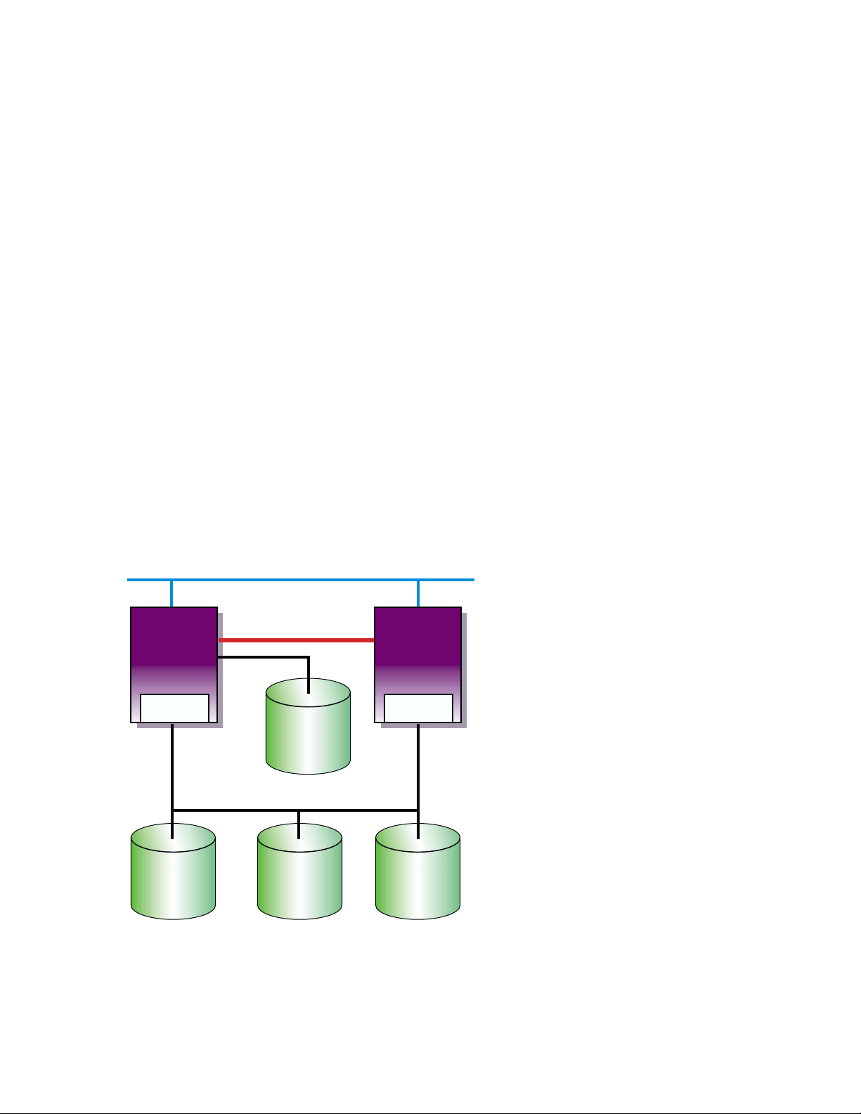
Figure 1–1 shows a generic two-node cluster with the minimum number
of disks.
• Tru64 UNIX disk
• Clusterwide root (
/), /usr, and /var
• Member 1 boot disk
• Member 2 boot disk
A minimum configuration cluster may have reduced availability due to the
lack of a quorum disk. As shown, with only two-member systems, both
systems must be operational to achieve quorum and form a cluster. If only
one system is operational, it will loop, waiting for the second system to boot
before a cluster can be formed. If one system crashes, you lose the cluster.
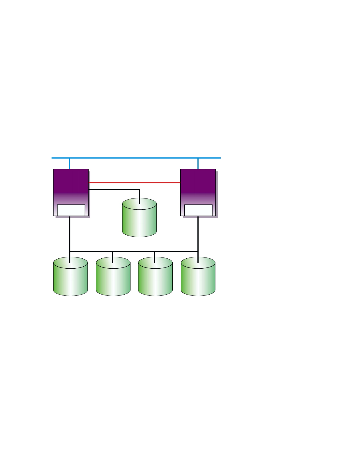
Figure 1–1: Two-Node Cluster with Minimum Disk Configuration and No
Quorum Disk
Network
Member
System
1
PCI SCSI
Adapter
Memory Channel
Tru64
UNIX
Disk
Member
System
2
PCI SCSI
Adapter
Cluster File
Figure 1–2 shows the same generic two-node cluster as shown in Figure 1–1,
but with the addition of a quorum disk. By adding a quorum disk, a cluster
may be formed if both systems are operational, or if either of the systems
and the quorum disk is operational. This cluster has a higher availability
than the cluster shown in Figure 1–1. See the TruCluster Server Cluster
1–6 Introduction
System
root (/)
/usr
/var
Shared SCSI Bus
Member 1
root (/)
swap
Member 2
root (/)
swap
ZK-1587U-AI
Page 29
Administration manual for a discussion of how and when to use a quorum
disk.
Figure 1–2: Generic Two-Node Cluster with Minimum Disk Configuration
and Quorum Disk
Network
Member
System
1
PCI SCSI
Adapter
Memory Channel
Tru64
UNIX
Disk
Member
System
2
PCI SCSI
Adapter
Shared SCSI Bus
Cluster File
System
root (/)
/usr
/var
Member 1
root (/)
swap
Member 1
root (/)
swap
Quorum
ZK-1588U-AI
1.6 Growing a Cluster from Minimum Storage to a NSPOF
Cluster
The following sections take a progression of clusters from a cluster with
minimum storage to a no-single-point-of-failure (NSPOF) cluster; a cluster
where one hardware failure will not interrupt the cluster operation:
• A cluster with minimum storage for highly available applications
(Section 1.6.1).
• A cluster with more storage, but the single SCSI bus is a single point
of failure (Section 1.6.2).
• Adding a second SCSI bus allows the use of LSM to mirror the /usr and
/var file systems and data disks. However, as LSM cannot mirror the
root (/), member system boot, swap, or quorum disks, so full redundancy
is not achieved (Section 1.6.3).
Introduction 1–7
Page 30

• Using a RAID array controller in transparent failover mode allows the
use of hardware RAID to mirror the disks. However, without a second
SCSI bus, second Memory Channel, and redundant networks, this
configuration is still not a NSPOF cluster (Section 1.6.4).
• By using an HSZ70, HSZ80, or HSG80 with multiple-bus failover enabled
you can use two shared SCSI buses to access the storage. Hardware
RAID is used to mirror the root (
the member system boot disks, data disks, and quorum disk (if used).
A second Memory Channel, redundant networks, and redundant power
must also be installed to achieve a NSPOF cluster (Section 1.6.5).
/), /usr, and /var file systems, and
1.6.1 Two-Node Clusters Using an UltraSCSI BA356 Storage Shelf
and Minimum Disk Configurations
This section takes the generic illustrations of our cluster example one step
further by depicting the required storage in storage shelves. The storage
shelves could be BA350, BA356 (non-UltraSCSI), or UltraSCSI BA356s.
The BA350 is the oldest model, and can only respond to SCSI IDs 0-6. The
non-Ultra BA356 can respond to SCSI IDs 0-6 or 8-14 (see Section 3.2). The
UltraSCSI BA356 also responds to SCSI IDs 0-6 or 8-14, but also can operate
at UltraSCSI speeds (see Section 3.2).
Figure 1–3 shows a TruCluster Server configuration using an UltraSCSI
BA356 storage unit. The DS-BA35X-DA personality module used in the
UltraSCSI BA356 storage unit is a differential-to-single-ended signal
converter, and therefore accepts differential inputs.
1–8 Introduction
______________________ Note _______________________
The figures in this section are generic drawings and do not show
shared SCSI bus termination, cable names, and so forth.
Page 31

Figure 1–3: Minimum Two-NodeCluster with UltraSCSI BA356 Storage Unit
Network
Tru64
UNIX
Disk
Member
System
1
Memory Channel
Host Bus Adapter (ID 6)
Shared
SCSI
Bus
ID 0
ID 1
ID 2
ID 3
ID 4
ID 5
ID 6
Memory
Channel
Interface
UltraSCSI
BA356
Clusterwide
/, /usr, /var
Member 1
Boot Disk
Member 2
Boot Disk
Quorum
Disk
PWR
Member
System
2
Memory Channel
Host Bus Adapter (ID 7)
Shared
SCSI
Bus
DS-BA35X-DA
Personality
Module
Clusterwide
Data Disks
Do not use for
data disk. May
be used for
redundant power
supply.
ZK-1591U-AI
The configuration shown in Figure 1–3 might represent a typical small or
training configuration with TruCluster Server Version 5.0A required disks.
In this configuration, because of the TruCluster Server Version 5.0A disk
requirements, there will only be two disks available for highly available
applications.
______________________ Note _______________________
Slot 6 in the UltraSCSI BA356 is not available because SCSI ID 6
is generally used for a member system SCSI adapter. However,
Introduction 1–9
Page 32

this slot can be used for a second power supply to provide fully
redundant power to the storage shelf.
Note that with the use of the cluster file system (See the TruCluster Server
Cluster Administration manual for a discussion of the cluster file system),
the clusterwide root (/), /usr, and /var file systems could be physically
placed on a private bus of either of the member systems. But, if that member
system was not available, the other member system(s) would not have access
to the clusterwide file systems. Therefore, placing the clusterwide root (/),
/usr, and /var file systems on a private bus is not recommended.
Likewise, the quorum disk could be placed on the local bus of either of the
member systems. If that member was not available, quorum could never be
reached in a two-node cluster. Placing the quorum disk on the local bus of a
member system is not recommended as it creates a single point of failure.
The individual member boot and swap partitions could also be placed on
a local bus of either of the member systems. If the boot disk for member
system 1 was on a SCSI bus internal to member 1, and the system was
unavailable due to a boot disk problem, other systems in the cluster could
not access the disk for possible repair. If the member system boot disks are
on a shared SCSI bus, they can be accessed by other systems on the shared
SCSI bus for possible repair.
By placing the swap partition on a system’s internal SCSI bus, you reduce
total traffic on the shared SCSI bus by an amount equal to the system’s
swap volume.
TruCluster Server Version 5.0A configurations require one or more disks to
hold the Tru64 UNIX operating system. The disk(s) are either private disk(s)
on the system that will become the first cluster member, or disk(s) on a
shared bus that the system can access.
We recommend that you place the /usr, /var, member boot disks, and
quorum disk on a shared SCSI bus connected to all member systems. After
installation, you have the option to reconfigure swap and can place the swap
disks on an internal SCSI bus to increase performance. See the TruCluster
Server Cluster Administration manual for more information.
1.6.2 Two-Node Clusters Using UltraSCSI BA356 Storage Units with
Increased Disk Configurations
The configuration shown in Figure 1–3 is a minimal configuration, with a
lack of disk space for highly available applications. Starting with Tru64
UNIX Version 5.0, 16 devices are supported on a SCSI bus. Therefore,
1–10 Introduction
Page 33

multiple BA356 storage units can be used on the same SCSI bus to allow
more devices on the same bus.
Figure 1–4 shows the configuration in Figure 1–3 with a second UltraSCSI
BA356 storage unit that provides an additional seven disks for highly
available applications.
Figure 1–4: Two-Node Cluster with Two UltraSCSI DS-BA356 Storage Units
Network
Host Bus Adapter (ID 6)
Tru64
UNIX
Disk
Data
disks
Do not use for
data disk. May
be used for
redundant power
supply.
Member
System
1
Memory Channel
UltraSCSI
BA356
Clusterwide
/, /usr, /var
Member 1
Boot Disk
Member 2
Boot Disk
Quorum
Disk
ID 4
ID 5
PWR
Memory
Channel
Interface
Shared
SCSI
Bus
ID 0
ID 1
ID 2
ID 3
ID 4
ID 5
ID 6
Member
System
2
Memory Channel
Host Bus Adapter (ID 7)
UltraSCSI
BA356
ID 8
ID 9
ID 10
Data
Disks
PWR
ID 11
ID 12
ID 13
ID 14 or
redundant
power
supply
ZK-1590U-AI
This configuration, while providing more storage, has a single SCSI bus that
presents a single point of failure. Providing a second SCSI bus would allow
the use of the Logical Storage Manager (LSM) to mirror the /usr and /var
file systems and the data disks across SCSI buses, removing the single SCSI
bus as a single point of failure for these file systems.
Introduction 1–11
Page 34

1.6.3 Two-Node Configurations with UltraSCSI BA356 Storage Units
and Dual SCSI Buses
By adding a second shared SCSI bus, you now have the capability to use the
Logical Storage Manager (LSM) to mirror data disks, and the clusterwide
/usr and /var file systems across SCSI buses.
______________________ Note _______________________
You cannot use LSM to mirror the clusterwide root (/), member
system boot, swap, or quorum disks, but you can use hardware
RAID.
Figure 1–5 shows a small cluster configuration with dual SCSI buses using
LSM to mirror the clusterwide /usr and /var file systems and the data
disks.
1–12 Introduction
Page 35

Figure 1–5: Two-Node Configurations with UltraSCSI BA356 Storage Units
and Dual SCSI Buses
Network
Tru64
UNIX
Disk
Member
System
1
Memory Channel
Host Bus Adapter (ID 6)
Host Bus Adapter (ID 6)
Memory
Channel
Interface
Member
System
2
Memory Channel
Host Bus Adapter (ID 7)
Host Bus Adapter (ID 7)
ID 0
ID 1
ID 2
ID 3
ID 4
ID 5
ID 6
UltraSCSI
BA356
Clusterwide
/, /usr, /var
Member 1
Boot Disk
Member 2
Boot Disk
Quorum
Disk
Data Disk
Data Disk
Redundant
PWR or not
used
PWR
UltraSCSI
BA356
ID 8
Data Disk
ID 9
Data Disk
ID 10
Data Disk
ID 11
Data Disk
ID 12
Data Disk
ID 13
Data Disk
ID 14 or
PWR
PWR
ID 0
ID 1
ID 2
ID 3
ID 4
ID 5
ID 6
UltraSCSI
BA356
Mirrored
/usr, /var
Not Used
Not Used
Not Used
Mirrored
Data Disk
Mirrored
Data Disk
Redundant
PWR or not
used
PWR
UltraSCSI
BA356
Mirrored
Data Disk
Mirrored
Data Disk
Mirrored
Data Disk
Mirrored
Data Disk
Mirrored
Data Disk
Mirrored
Data Disk
ID 14 or
PWR
PWR
ZK-1593U-AI
ID 8
ID 9
ID 10
ID 11
ID 12
ID 13
By using LSM to mirror the /usr and /var file systems and the data disks,
we have achieved higher availability. But, even if you have a second Memory
Channel and redundant networks, because we cannot use LSM to mirror the
clusterwide root (/), quorum, or the member boot disks, we do not have a
no-single-point-of-failure (NSPOF) cluster.
1.6.4 Using Hardware RAID to Mirror the Clusterwide Root File
System and Member System Boot Disks
You can use hardware RAID with any of the supported RAID array
controllers to mirror the clusterwide root (/), quorum, and member boot
disks. Figure 1–6 shows a cluster configuration using an HSZ70 RAID array
controller. An HSZ40, HSZ50, HSZ80, or HSG80 could be used instead of the
Introduction 1–13
Page 36

HSZ70. The array controllers can be configured as a dual redundant pair. If
you want the capability to fail over from one controller to another controller,
you must install the second controller. Also, you must set the failover mode.
Figure 1–6: Cluster Configuration with HSZ70 Controllers in Transparent
Failover Mode
Network
Member
Member
System
System
1
1
Memory
Channel
Member
System
2
Interface
Memory Channel
Host Bus Adapter (ID 6)
Tru64
UNIX
Disk
HSZ70 HSZ70
StorageWorks
RAID Array 7000
Memory Channel
Host Bus Adapter (ID 7)
ZK-1589U-AI
In Figure 1–6 the HSZ40, HSZ50, HSZ70, HSZ80, or HSG80 has transparent
failover mode enabled (SET FAILOVER COPY = THIS_CONTROLLER). In
transparent failover mode, both controllers are connected to the same shared
SCSI bus and device buses. Both controllers service the entire group of
storagesets, single-disk units, or other storage devices. Either controller can
continue to service all of the units if the other controller fails.
The assignment of HSZ target IDs can be balanced between the
controllers to provide better system performance. See the RAID
array controller documentation for information on setting up
storagesets.
1–14 Introduction
______________________ Note _______________________
Page 37

Note that in the configuration shown in Figure 1–6, there is only one shared
SCSI bus. Even by mirroring the clusterwide root and member boot disks,
the single shared SCSI bus is a single point of failure.
1.6.5 Creating a NSPOF Cluster
To create a no-single-point-of-failure (NSPOF) cluster:
• Use hardware RAID to mirror the clusterwide root (/), /usr, and /var
file systems, the member boot disks, quorum disk (if present), and data
disks
• Use at least two shared SCSI buses to access dual-redundant RAID
array controllers set up for multiple-bus failover mode (HSZ70, HSZ80,
and HSG80)
• Install a second Memory Channel interface for redundancy
• Install redundant power supplies
• Install redundant networks
• Connect the systems and storage to an uninterruptable power supply
(UPS)
Tru64 UNIX support for multipathing provides support for multiple-bus
failover.
______________________ Notes ______________________
Only the HSZ70, HSZ80, and HSG80 are capable of supporting
multiple-bus failover (SET MULTIBUS_FAILOVER COPY =
THIS_CONTROLLER).
Partitioned storagesets and partitioned single-disk units cannot
function in multiple-bus failover dual-redundant configurations
with the HSZ70 or HSZ80. You must delete any partitions before
configuring the controllers for multiple-bus failover.
Partitioned storagesets and partitioned single-disk units are
supported with the HSG80 and ACS V8.5.
Figure 1–7 shows a cluster configuration with dual-shared SCSI buses and a
storage array with dual-redundant HSZ70s. If there is a failure in one SCSI
bus, the member systems can access the disks over the other SCSI bus.
Introduction 1–15
Page 38

Figure 1–7: NSPOF Cluster using HSZ70s in Multiple-Bus Failover Mode
Networks
Tru64
UNIX
Disk
Member System 1 Member System 2
Memory Channel (mca1)
Memory Channel (mca0)
Host Bus Adapter (ID 6)
Host Bus Adapter (ID 6)
Memory
Channel
Interfaces
Memory Channel (mca1)
Memory Channel (mca0)
Host Bus Adapter (ID 7)
Host Bus Adapter (ID 7)
HSZ70
StorageWorks
RAID Array 7000
HSZ70
ZK-1594U-AI
Figure 1–8 shows a cluster configuration with dual-shared Fibre Channel
SCSI buses and a storage array with dual-redundant HSG80s configured for
multiple-bus failover.
1–16 Introduction
Page 39

Figure 1–8: NSPOF Fibre Channel Cluster using HSG80s in Multiple-Bus
Failover Mode
Member
System
1
Member
System
2
KGPSA
KGPSA
DSGGA DSGGA
HSG80
HSG80
RA8000/
ESA12000
KGPSA
KGPSA
HSG80
HSG80
RA8000/
ESA12000
ZK-1533U-AI
1.7 Overview of Setting up the TruCluster Server Hardware
Configuration
To set up a TruCluster Server hardware configuration, follow these steps:
1. Plan your hardware configuration. (See Chapter 3, Chapter 4,
Chapter 6, Chapter 9, and Chapter 10).
2. Draw a diagram of your configuration.
3. Compare your diagram with the examples in Chapter 3, Chapter 6,
and Chapter 9.
4. Identify all devices, cables, SCSI adapters, and so forth. Use the
diagram you just constructed.
5. Prepare the shared storage by installing disks and configuring any RAID
controller subsystems (See Chapter 3, Chapter 6, and Chapter 9 and the
documentation for the StorageWorks enclosure or RAID controller).
Introduction 1–17
Page 40

6. Install signal converters in the StorageWorks enclosures, if applicable
(see Chapter 3 and Chapter 9).
7. Connect storage to the shared SCSI buses. Terminate each bus. Use
Y cables or trilink connectors where necessary (see Chapter 3 and
Chapter 9).
For a Fibre Channel configuration, connect the HSG80 controllers to
the switches. You want the HSG80 to recognize the connections to the
systems when the systems are powered on.
8. Prepare the member systems by installing:
• Additional Ethernet or Asynchronous Transfer Mode (ATM) network
adapters for client networks (see Chapter 7).
• SCSI bus adapters. Ensure that adapter terminators are set
correctly. Connect the systems to the shared SCSI bus (see
Chapter 4 or Chapter 10).
• The KGPSA host bus adapter for Fibre Channel configurations.
Ensure that the KGPSA is operating in the correct mode (
FABRIC or
LOOP). Connect the KGPSA to the switch (see Chapter 6).
• Memory Channel adapters. Ensure that jumpers are set correctly
(see Chapter 5).
9. Connect the Memory Channel adapters to each other or to the Memory
Channel hub as appropriate (see Chapter 5).
10. Turn on the Memory Channel hubs and storage shelves, then turn on
the member systems.
11. Install the firmware, set SCSI IDs, and enable fast bus speed as
necessary (see Chapter 4 and Chapter 10).
12. Display configuration information for each member system, and ensure
that all shared disks are seen at the same device number (see Chapter 4,
Chapter 6, or Chapter 10).
1–18 Introduction
Page 41

Hardware Requirements and Restrictions
This chapter describes the hardware requirements and restrictions for
a TruCluster Server cluster. It includes lists of supported cables, trilink
connectors, Y cables, and terminators.
See the TruCluster Server Software Product Description (SPD) for the latest
information about supported hardware.
2.1 TruCluster Server Member System Requirements
The requirements for member systems in a TruCluster Server cluster are as
follows:
• Each supported member system requires a minimum firmware revision.
See the Release Notes Overview supplied with the Alpha Systems
Firmware Update CD-ROM.
You can also obtain firmware information from the Web at
http://www.compaq.com/support/. Select Alpha Systems from
the downloadable drivers & utilities menu. Check the release
notes for the appropriate system type to determine the firmware version
required.
• TruCluster Server Version 5.0A supports eight-member cluster
configurations as follows:
2
– FibreChannel: Eight-member systems may be connected to common
storage over Fibre Channel in a fabric (switch) configuration.
– Parallel SCSI: Only four of the member systems may be connected to
any one SCSI bus, but you can have multiple SCSI buses connected
to different sets of nodes, and the sets of nodes may overlap. We
recommend you use a DS-DWZZH-05 UltraSCSI hub with fair
arbitration enabled when connecting four-member systems to a
common SCSI bus.
• TruCluster Server does not support the XMI CIXCD on an AlphaServer
8x00, GS60, GS60E, or GS140 system.
2.2 Memory Channel Restrictions
The Memory Channel interconnect is used for cluster communications
between the member systems.
Hardware Requirements and Restrictions 2–1
Page 42

There are currently three versions of the Memory Channel product; Memory
Channel 1, Memory Channel 1.5, and Memory Channel 2. The Memory
Channel 1 and Memory Channel 1.5 products are very similar (the PCI
adapter for both versions is the CCMAA module) and are generally referred
to as MC1 throughout this manual. The Memory Channel 2 product
(CCMAB module) is referred to as MC2.
Ensure that you abide by the following Memory Channel restrictions:
• The DS10, DS20, DS20E, and ES40 systems only support MC2 hardware.
• If redundant Memory Channel adapters are used with a DS10, they must
be jumpered for 128 MB and not the default of 512 MB.
• If you use the MC API library functions in a 2-node TruCluster Server
configuration, you cannot use virtual hub mode, you must use a Memory
Channel hub and standard hub mode.
• If you have redundant MC2 modules on a system jumpered for 512 MB,
you cannot have two MC2 modules on the same PCI bus.
• The MC1 adapter cannot be cabled to a MC2 adapter.
– Donot use the BC12N link cable with the CCMAB MC2 adapter.
– Donot use the BN39B link cable with the CCMAA MC1 adapter.
• Redundant Memory Channels are supported within a mixed Memory
Channel configuration, as long as MC1 adapters are connected to other
MC1 adapters and MC2 adapters are connected to MC2 adapters.
• A Memory Channel interconnect can use either virtual hub mode (two
member systems connected without a Memory Channel hub) or standard
mode (two or more systems connected to a hub). A TruCluster Server
cluster with three or more member systems must be jumpered for
standard hub mode and requires a Memory Channel hub.
• If Memory Channel modules are jumpered for virtual hub mode, all
Memory Channel modules on a system must be jumpered in the same
manner, either virtual hub 0 (VH0) or virtual hub 1 (VH1). You cannot
have one Memory Channel module jumpered for VH0 and another
jumpered for VH1 on the same system.
• The maximum length of an MC1 BC12N and MC2 BN39B link cable is
10 meters.
• Always check a Memory Channel link cable for bent or broken pins.
Be sure that you do not bend or break any pins when you connect or
disconnect a cable.
• For AlphaServer 1000A systems, the Memory Channel adapter must be
installed on the primary PCI (in front of the PCI-to-PCI bridge chip) in
PCI slots 11, 12, or 13 (the top three slots).
2–2 Hardware Requirements and Restrictions
Page 43

• For AlphaServer 2000 systems, the B2111-AA module must be at
Revision H or higher.
For AlphaServer 2100 systems, the B2110-AA module must be at
Revision L or higher.
Use the
at a supported revision as follows:
P00>>> examine -b econfig:20008
econfig: 20008 04
P00>>>
If a hexadecimal value of 04 or greater is returned, the I/O module
supports Memory Channel.
If a hexadecimal value of less than 04 is returned, the I/O module is not
supported for Memory Channel usage.
Order an H3095-AA module to upgrade an AlphaServer 2000 or an
H3096-AA module to upgrade an AlphaServer 2100 to support Memory
Channel.
• For AlphaServer 2100A systems, the Memory Channel adapter must
be installed in PCI 4 through PCI 7 (slots 6, 7, 8, and 9), the bottom
four PCI slots.
• For AlphaServer 8200, 8400, GS60, GS60E, or GS140 systems, the
Memory Channel adapter must be installed in slots 0-7 of a DWLPA
PCIA option; there are no restrictions for a DWLPB.
examine console command to determine if these modules are
• If a TruCluster Server cluster configuration utilizes multiple Memory
Channel adapters in standard hub mode, the Memory Channel adapters
must be connected to separate Memory Channel hubs. The first Memory
Channel adapter (mca0) in each system must be connected to one
Memory Channel hub. The second Memory Channel adapter (mcb0)in
each system must be connected to a second Memory Channel hub. Also,
each Memory Channel adapter on one system must be connected to the
same linecard in each Memory Channel hub.
2.3 Fibre Channel Requirements and Restrictions
Table 2–1 shows the supported AlphaServer systems with Fibre Channel
and the number of KGPSA-BC PCI-to-Fibre Channel adapters supported
on each system.
Hardware Requirements and Restrictions 2–3
Page 44

Table 2–1: AlphaServer Systems Supported for Fibre Channel
AlphaServer Number of KGPSA-BC Adapters
AlphaServer 800
AlphaServer 1200
AlphaServer 4000, 4000A, or 4100
Compaq AlphaServer DS10
Compaq AlphaServer DS20 and DS20E
Compaq AlphaServer ES40
AlphaServer 8200 or 8400
Compaq AlphaServer GS60, GS60E,
and GS140
a
The KGPSA-BC/CA PCI-to-Fibre Channel adapters are only supported on the DWLPB PCIA option;
they are not supported on the DWLPA.
a
a
Supported
2
4
4
1
2
4
32 (2 per DWLPB for throughput, 4
per DWLPB for connectivity)
32 (2 per DWLPB for throughput, 4
per DWLPB for connectivity)
The following requirements and restrictions apply to the use of Fibre
Channel with the TruCluster Server:
• The HSG80 requires Array Control Software (ACS) Version 8.5.
• A maximum of four member systems is supported.
• The only supported Fibre Channel adapters are the KGPSA-BC and
KGPSA-CA PCI-to-Fibre Channel host bus adapters.
• The only Fibre Channel switches supported are the 8/16 Port DSGGA or
DSGGB Fibre Channel switches.
• The Fibre Channel switches support both shortwave (GBIC-SW) and
longwave (GBIC-LW) Giga Bit Interface Converter (GBIC) modules.
The GBIC-SW module supports 50-micron, multimode fibre cables with
the standard subscriber connector (SC connector) in lengths up to 500
meters. The GBIC-LW supports 9-micron, single-mode fibre cables with
the SC connector in lengths up to 10 kilometers.
The KGPSA-BC/CA PCI-to-Fibre Channel host bus adapters and the
HSG80 RAID controller support the 50-micron Gigabit Link Module
(GLM) for fibre connections. Therefore, only the 50-micron multimode
fibre optical cable is supported between the KGPSA and switch and the
switch and HSG80 for cluster configurations. You must install GBIC-SW
GBICs in the Fibre Channel switches for communication between the
switches and KGPSA or HSG80.
• A maximum of three cascaded switches is supported, with a maximum of
two hops between switches. The maximum hop length is 10 km longwave
single-mode or 500 meters via shortwave multimode Fibre Channel cable.
2–4 Hardware Requirements and Restrictions
Page 45

• The Fibre Channel RAID Array 8000 (RA8000) midrange departmental
storage subsystem and Fibre Channel Enterprise Storage Array 12000
(ESA12000) house two HSG80 dual-channel controllers. There are
provisions for six UltraSCSI channels.
• Only disk devices attached to the HSG80 Fibre Channel to Six Channel
UltraSCSI Array controller are supported with the TruCluster Server
product.
• No tape devices are supported.
• Tru64 UNIX Version 5.0A limits the number of Fibre Channel targets
to 126.
• Tru64 UNIX Version 5.0A allows up to 255 LUNs per target.
• The HSG80 supports transparent and multiple-bus failover mode when
used in a TruCluster Server Version 5.0A configuration. Multiple-bus
failover is recommended for high availability in a cluster.
• A storage array with dual-redundant HSG80 controllers in transparent
mode failover is two targets and consumes four ports on a switch.
• A storage array with dual-redundant HSG80 controllers in multiple-bus
failover is four targets and consumes 4 ports on a switch.
• Each KGPSA is one target.
• The HSG80 documentation refers to the controllers as Controllers A (top)
and B (bottom). Each controller provides two ports (left and right). (The
HSG80 documentation refers to these ports as Port 1 and 2, respectively.)
In transparent failover mode, only one left port and one right port are
active at any given time.
With transparent failover enabled, assuming that the left port of the top
controller and the right port of the bottom controller are active, if the top
controller fails in such a way that it can no longer properly communicate
with the switch, then its functions will automatically fail over to the
bottom controller (and vice versa).
• In transparent failover mode, you can configure which controller
presents each HSG80 storage element (unit) to the cluster. Ordinarily,
the left port of either controller serves the units designated D0 through
D99, and the right port serves those designated D100 through D199.
• In multiple-bus failover mode, all units (D0 through D199) are visible to
all host ports, but accessible only through one controller at any specific
time. The host can control the failover process by moving unit(s) from
one controller to the other controller.
Hardware Requirements and Restrictions 2–5
Page 46

2.4 SCSI Bus Adapter Restrictions
To connect a member system to a shared SCSI bus, you must install a SCSI
bus adapter in an I/O bus slot.
The Tru64 UNIX operating system supports a maximum of 64 I/O buses.
TruCluster Server supports a total of 32 shared I/O buses using KZPSA-BB
host bus adapters, KZPBA-CB UltraSCSI host bus adapters, or KGPSA
Fibre Channel host bus adapters.
The following sections describe the SCSI adapter restrictions in more detail.
2.4.1 KZPSA-BB SCSI Adapter Restrictions
KZPSA-BB SCSI adapters have the following restrictions:
• The KZPSA-BB requires A12 firmware.
• If you have a KZPSA-BB adapter installed in an AlphaServer that
supports the bus_probe_algorithm console variable (for example, the
AlphaServer 800, 1000, 1000A, 2000, 2100, or 2100A systems support
the variable), you must set the bus_probe_algorithm console variable
to new by entering the following command:
>>> set bus_probe_algorithm new
Use the show bus_probe_algorithm console command to determine if
your system supports the variable. If the response is null or an error,
there is no support for the variable. If the response is anything other
than new, you must set it to new.
• On AlphaServer 1000A and 2100A systems, updating the firmware on
the KZPSA-BB SCSI adapter is not supported when the adapter is
behind the PCI-to-PCI bridge.
2.4.2 KZPBA-CB SCSI Bus Adapter Restrictions
KZPBA-CB UltraSCSI adapters have the following restrictions:
• Each system supporting the KZPBA-CB UltraSCSI host adapter limits
the number of adapters that may be installed. The maximum number of
KZPBA-CB UltraSCSI host adapters supported with TruCluster Server
follow:
– AlphaServer 800: 2
– AlphaServer 1000A and 1200: 4
– AlphaServer 4000: 8; only one KZPBA-CB is supported in IOD0
(PCI0).
– AlphaServer 4100: 5; only one KZPBA-CB is supported in IOD0
(PCI0).
2–6 Hardware Requirements and Restrictions
Page 47

– AlphaServer 8200, 8400, GS60, GS60E, GS140: 32
The KZPBA-CB is supported on the DWLPB only; it is not supported
on the DWLPA module.
– AlphaServer DS10: 2
– AlphaServer DS20/DS20E: 4
– AlphaServer ES40: 5
• A maximum of four HSZ50, HSZ70, or HSZ80 RAID array controllers can
be placed on a single KZPBA-CB UltraSCSI bus. Only two redundant
pairs of array controllers are allowed on one SCSI bus.
• The KZPBA-CB requires ISP 1020/1040 firmware Version 5.57 (or
higher), which is available with the system SRM console firmware on the
Alpha Systems Firmware 5.3 Update CD-ROM (or later).
• The maximum length of any differential SCSI bus segment is 25 meters,
including the length of the SCSI bus cables and SCSI bus internal to the
SCSI adapter, hub, or storage device. A SCSI bus may have more than
one SCSI bus segment (see Section 3.1).
• See the KZPBA-CB UltraSCSI Storage Adapter Module
(AA-R5XWD-TE) for more information.
2.5 Disk Device Restrictions
The restrictions for disk devices are as follows:
• Disks on shared SCSI buses must be installed in external storage shelves
or behind a RAID array controller.
• TruCluster Server does not support Prestoserve on any shared disk.
2.6 RAID Array Controller Restrictions
RAID array controllers provide high performance, high availability, and high
connectivity access to SCSI devices through a shared SCSI bus.
RAID controllers can be configured with the number of SCSI IDs as shown
in Table 2–2.
Table 2–2: RAID Controller SCSI IDs
RAID Controller Number of SCSI IDs Supported
HSZ20
HSZ40
HSZ50
HSZ70
4
4
4
8
Release Notes
Hardware Requirements and Restrictions 2–7
Page 48

Table 2–2: RAID Controller SCSI IDs (cont.)
RAID Controller Number of SCSI IDs Supported
HSZ80
HSG80 N/A
2.7 SCSI Signal Converters
If you are using a standalone storage shelf with a single-ended SCSI
interface in your cluster configuration, you must connect it to a SCSI signal
converter. SCSI signal converters convert wide, differential SCSI to narrow
or wide, single-ended SCSI and vice versa. Some signal converters are
standalone desktop units and some are StorageWorks building blocks (SBBs)
that you install in storage shelves disk slots.
______________________ Note _______________________
The UltraSCSI hubs could probably be listed here as they contain
a DOC (DWZZA on a chip) chip, but they are covered separately
in Section 2.8.
The restrictions for SCSI signal converters are as follows:
• If you remove the cover from a standalone unit, be sure to replace the
star washers on all four screws that hold the cover in place when you
reattach the cover. If the washers are not replaced, the SCSI signal
converter may not function correctly because of noise.
• If you want to disconnect a SCSI signal converter from a shared SCSI
bus, you must turn off the signal converter before disconnecting the
cables. To reconnect the signal converter to the shared bus, connect the
cables before turning on the signal converter. Use the power switch to
turn off a standalone SCSI signal converter. To turn off an SBB SCSI
signal converter, pull it from its disk slot.
15
• If you observe any “bus hung” messages, your DWZZA signal converters
may have the incorrect hardware. In addition, some DWZZA signal
converters that appear to have the correct hardware revision may cause
problems if they also have serial numbers in the range of CX444xxxxx
to CX449xxxxx.
To upgrade a DWZZA-AA or DWZZA-VA signal converter to the correct
revision, use the appropriate field change order (FCO), as follows:
– DWZZA-AA-F002
– DWZZA-VA-F001
2–8 Hardware Requirements and Restrictions
Page 49

2.8 DS-DWZZH-03 and DS-DWZZH-05 UltraSCSI Hubs
The DS-DWZZH-03 and DS-DWZZH-05 series UltraSCSI hubs are the only
hubs supported in a TruCluster Server configuration. They are SCSI-2and draft SCSI-3-compliant SCSI 16-bit signal converters capable of data
transfer rates of up to 40 MB/sec.
These hubs can be listed with the other SCSI bus signal converters, but as
they are used differently in cluster configurations they will be discussed
differently in this manual.
A DS-DWZZH-03 or DS-DWZZH-05 UltraSCSI hub can be installed in:
• A StorageWorks UltraSCSI BA356 shelf (which has the required
180-watt power supply).
• The lower righthand device slot of the BA370 shelf within the RA7000
or ESA 10000 RAID array subsystems. This position minimizes cable
lengths and interference with disks.
• A wide BA356 which has been upgraded to the 180-watt power supply
with the DS-BA35X-HH option.
A DS-DWZZH-03 or DS-DWZZH-05 UltraSCSI hub:
• Improves the reliability of the detection of cable faults.
• Provides for bus isolation of cluster systems while allowing the remaining
connections to continue to operate.
• Allows for more separation of systems and storage in a cluster
configuration, because each SCSI bus segment can be up to 25 meters
in length. This allows a total separation of nearly 50 meters between
a system and the storage.
______________________ Note _______________________
The DS-DWZZH-03/05 UltraSCSI hubs cannot be connected to a
StorageWorks BA35X storage shelf because the storage shelf does
not provide termination power to the hub.
2.9 SCSI Cables
If you are using shared SCSI buses, you must determine if you need
cables with connectors that are low-density 50-pins, high-density 50-pins,
high-density 68-pins (HD68), or VHDCI (UltraSCSI). If you are using an
UltraSCSI hub, you will need HD68 to VHDCI and VHDCI to VHDCI cables.
In some cases, you also have the choice of straight or right-angle connectors.
Hardware Requirements and Restrictions 2–9
Page 50

In addition, each supported cable comes in various lengths. Use the shortest
possible cables to adhere to the limits on SCSI bus length.
Table 2–3 describes each supported cable and the context in which you would
use the cable. Note that there are cables with the Compaq 6-3 part number
that are not listed, but are equivalent to the cables listed.
Table 2–3: Supported SCSI Cables
Cable Connector
Density
BN21W-0B Three high 68-pin A Y cable that can be attached to a
BN21M One low, one
high
BN21K,
Two HD68 68-pin Connects BN21W Y cables or wide
BN21L, or
328215-00X
BN38C or
BN38D
One HD68, one
VHDCI
BN37A Two VHDCI VHDCI
199629-002or
Two high 50-pin
189636-002
146745-003or
Two high 50-pin
146776-003
Pins
50-pin
LD to
68-pin
HD
HD68 to
VHDCI
to
VHDCI
HD to
68-pin
HD
HD to
50-pin
HD
Configuration Use
KZPSA-BB or KZPBA-CB if there
is no room for a trilink connector.
It can be used with a terminator to
provide external termination.
Connects the single-ended end of
a DWZZA-AA or DWZZB-AA to
a TZ885 or TZ887.
a
devices. For example, connects
KZPBA-CBs, KZPSA-BBs, HSZ40s,
HSZ50s, the differential sides of
two SCSI signal converters, or a
DWZZB-AA to a BA356.
Connects a KZPBA-CB or KZPSA-BB
to a port on an UltraSCSI hub.
Connects two VHDCI trilinks to
each other or an UltraSCSI hub to a
trilink on an HSZ70 or HSZ80
Connect a Compaq 20/40 GB DLT
Tape Drive to a DWZZB-AA
Daisy-chain two Compaq 20/40
GB DLT Tape Drives
a
Do not use a KZPBA-CB with a DWZZA-AA or DWZZB-AA and a TZ885 or TZ887. The DWZZAs and
DWZZBs can not operate at UltraSCSI speed.
Always check a SCSI cable for bent or broken pins. Be sure that you do not
bend or break any pins when you connect or disconnect a cable.
2–10 Hardware Requirements and Restrictions
Page 51

2.10 SCSI Terminators and Trilink Connectors
Table 2–4 describes the supported trilink connectors and SCSI terminators
and the context in which you would use them.
Table 2–4: Supported SCSI Terminators and Trilink Connectors
Trilink
Connector or
Terminator
H885-AA Three 68-pin Trilink connector that attaches to high-density,
H8574-A or
H8860-AA
341102-001
H879-AA High 68-pin Terminates an H885-AA trilink connector
H8861-AA VHDCI 68-pin VHDCItrilinkconnector that attaches to VHDCI
H8863-AA VHDCI 68-pin Terminate a VHDCI trilink connector.
Density
Low 50-pin Terminates a TZ885 or TZ887 tape drive.
High 50-pin Terminates a Compaq 20/40 GB DLT Tape Drive
Pins
Configuration Use
68-pin cables or devices, such as a KZPSA-BB,
KZPBA-CB, HSZ40, HSZ50, or the differential
side of a SCSI signal converter. Can be
terminated with an H879-AA terminator to
provide external termination.
or BN21W-0B Y cable.
68-pin cables, UltraSCSI BA356 JA1, and HSZ70
or HSZ80 RAID controllers. Can be terminated
with an H8863-AA terminator if necessary.
The requirements for trilink connectors are as follows:
• If you connect a SCSI cable to a trilink connector, do not block access to
the screws that mount the trilink, or you will be unable to disconnect the
trilink from the device without disconnecting the cable.
• Do not install an H885-AA trilink if installing it will block an adjacent
peripheral component interconnect (PCI) port. Use a BN21W-0B Y cable
instead.
Hardware Requirements and Restrictions 2–11
Page 52

Page 53

3
Shared SCSI Bus Requirements and
Configurations Using UltraSCSI Hardware
A TruCluster Server cluster uses shared SCSI buses, external storage
shelves or RAID controllers, and supports disk mirroring and fast file system
recovery to provide high data availability and reliability.
This chapter:
• Introduces SCSI bus configuration concepts
• Describes requirements for the shared SCSI bus
• Provides procedures for cabling TruCluster Server radial configurations
using UltraSCSI hubs and:
– Dual-redundant HSZ70 or HSZ80 RAID array controllers enabled
for simultaneous failover
– Dual-redundant HSZ70 or HSZ80 RAID array controllers enabled
for multiple-bus failover
• Provides diagrams of TruCluster Server storage configurations using
UltraSCSI hardware configured for radial connections
______________________ Note _______________________
Although the UltraSCSI BA356 might have been included in
this chapter with the other UltraSCSI devices, it is not. The
UltraSCSI BA356 is covered in Chapter 9 with the configurations
using external termination. It cannot be cabled directly to an
UltraSCSI hub because it does not provide SCSI bus termination
power (termpwr).
In addition to using only supported hardware, adhering to the requirements
described in this chapter will ensure that your cluster operates correctly.
Chapter 9 contains additional information about using SCSI bus signal
converters, and also contains diagrams of TruCluster Server configurations
using UltraSCSI and non-UltraSCSI storage shelves and RAID array
controllers. The chapter also covers the older method of using external
Shared SCSI Bus Requirements and Configurations Using UltraSCSI Hardware 3–1
Page 54

termination and covers radial configurations with the DWZZH UltraSCSI
hubs and non-UltraSCSI RAID array controllers.
This chapter discusses the following topics:
• Shared SCSI bus configuration requirements (Section 3.1)
• SCSI bus performance (Section 3.2)
• SCSI bus device identification numbers (Section 3.3)
• SCSI bus length (Section 3.4)
• SCSI bus termination (Section 3.5)
• UltraSCSI hubs (Section 3.6)
• Configuring UltraSCSI hubs with RAID array controllers (Section 3.7)
3.1 Shared SCSI Bus Configuration Requirements
A shared SCSI bus must adhere to the following requirements:
• Only an external bus can be used for a shared SCSI bus.
• SCSI bus specifications set a limit of 8 devices on an 8-bit (narrow) SCSI
bus. The limit is 16 devices on a 16-bit SCSI bus (wide). See Section 3.3
for more information.
• The length of each physical bus is strictly limited. See Section 3.4 for
more information.
• You can directly connect devices only if they have the same transmission
mode (differential or single-ended) and data path (narrow or wide). Use
a SCSI signal converter to connect devices with different transmission
modes. See Section 9.1 for information about the DWZZA (BA350) or
DWZZB (BA356) signal converters or the DS-BA35X-DA personality
module (which acts as a differential to single-ended signal converter
for the UltraSCSI BA356).
• For each SCSI bus segment, you can have only two terminators, one
at each end. A physical SCSI bus may be composed of multiple SCSI
bus segments.
• If you do not use an UltraSCSI hub, you must use trilink connectors
and Y cables to connect devices to a shared bus, so you can disconnect
the devices without affecting bus termination. See Section 9.2 for more
information.
• Be careful when performing maintenance on any device that is on a
shared bus because of the constant activity on the bus. Usually, to
perform maintenance on a device without shutting down the cluster, you
must be able to isolate the device from the shared bus without affecting
bus termination.
3–2 Shared SCSI Bus Requirements and Configurations Using UltraSCSI Hardware
Page 55

• All supported UltraSCSI host adapters support UltraSCSI disks at
UltraSCSI speeds in UltraSCSI BA356 shelves, RA7000 or ESA10000
storage arrays (HSZ70 and HSZ80), or RA8000 or ESA12000 storage
arrays (HSZ80 and HSG80). Older, non-UltraSCSI BA356 shelves are
supported with UltraSCSI host adapters and host RAID controllers as
long as they contain no UltraSCSI disks.
• UltraSCSI drives and fast wide drives can be mixed together in an
UltraSCSI BA356 shelf (see Chapter 9).
• Differential UltraSCSI adapters may be connected to either (or both)
a non-UltraSCSI BA356 shelf (via a DWZZB-VW) and the UltraSCSI
BA356 shelf (via the DS-BA35X-DA personality module) on the same
shared SCSI bus. The UltraSCSI adapter negotiates maximum transfer
speeds with each SCSI device (see Chapter 9).
• The HSZ70 and HSZ80 UltraSCSI RAID controllers have a wide
differential UltraSCSI host bus with a Very High Density Cable
Interconnect (VHDCI) connector. HSZ70 and HSZ80 controllers will
work with fast and wide differential SCSI adapters (for example,
KZPSA-BB) at fast SCSI speeds.
• Fast, wide SCSI drives (green StorageWorks building blocks (SBBs) with
part numbers ending in -VW) may be used in an UltraSCSI BA356 shelf.
• Do not use fast, narrow SCSI drives (green SBBs with part numbers
ending in -VA) in any shelf that could assign the drive a SCSI ID greater
than 7. It will not work.
• The UltraSCSI BA356 requires a 180-watt power supply (BA35X-HH).
It will not function properly with the older, lower-wattage BA35X-HF
universal 150-watt power supply (see Chapter 9).
• An older BA356 that has been retrofitted with a BA35X-HH 180-watt
power supply and DS-BA35X-DA personality module is still only FCC
certified for Fast 10 configurations (see Chapter 9).
3.2 SCSI Bus Performance
Before you set up a SCSI bus, it is important that you understand a number
of issues that affect the viability of a bus and how the devices connected to it
operate. Specifically, bus performance is influenced by the following factors:
• Transmission method
• Data path
• Bus speed
The following sections describe these factors.
Shared SCSI Bus Requirements and Configurations Using UltraSCSI Hardware 3–3
Page 56

3.2.1 SCSI Bus Versus SCSI Bus Segments
An UltraSCSI bus may be comprised of multiple UltraSCSI bus segments.
Each UltraSCSI bus segment is comprised of electrical conductors that
may be in a cable or a backplane, and cable or backplane connectors. Each
UltraSCSI bus segment must have a terminator at each end of the bus
segment.
Up to two UltraSCSI bus segments may be coupled together with UltraSCSI
hubs or signal converters, increasing the total length of the UltraSCSI bus.
3.2.2 Transmission Methods
Two transmission methods can be used in a SCSI bus:
• Single-ended — In a single-ended SCSI bus, one data lead and one
ground lead are utilized for the data transmission. A single-ended
receiver looks only at the signal wire as the input. The transmitted
signal arrives at the receiving end of the bus on the signal wire
somewhat distorted by signal reflections. The length and loading of
the bus determine the magnitude of this distortion. This transmission
method is economical, but is more susceptible to noise than the
differential transmission method, and requires short cables. Devices
with single-ended SCSI devices include the following:
– BA350, BA356, and UltraSCSI BA356 storage shelves
– Single-endedside of a SCSI signal converter or personality module
• Differential — Differential signal transmission uses two wires to
transmit a signal. The two wires are driven by a differential driver that
places a signal on one wire (+SIGNAL) and another signal that is 180
degrees out of phase (-SIGNAL) on the other wire. The differential
receiver generates a signal output only when the two inputs are different.
As signal reflections occur virtually the same on both wires, they are not
seen by the receiver, because it only sees differences on the two wires.
This transmission method is less susceptible to noise than single-ended
SCSI and enables you to use longer cables. Devices with differential
SCSI interfaces include the following:
– KZPBA-CB
– KZPSA-BB
– HSZ40, HSZ50, HSZ70, and HSZ80 controllers
– Differential side of a SCSI signal converter or personality module
You cannot use the two transmission methods in the same SCSI bus
segment. For example, a device with a differential SCSI interface must be
connected to another device with a differential SCSI interface. If you want to
3–4 Shared SCSI Bus Requirements and Configurations Using UltraSCSI Hardware
Page 57

connect devices that use different transmission methods, use a SCSI signal
converter between the devices. The DS-BA35X-DA personality module is
discussed in Section 9.1.2.2. See Section 9.1 for information about using the
DWZZ* series of SCSI signal converters.
You cannot use a DWZZA or DWZZB signal converter at UltraSCSI speeds
for TruCluster Server if there are any UltraSCSI disks on the bus, because
the DWZZA or DWZZB will not operate correctly at UltraSCSI speed.
The DS-BA35X-DA personality module contains a signal converter for
the UltraSCSI BA356. It is the interface between the shared differential
UltraSCSI bus and the UltraSCSI BA356 internal single-ended SCSI bus.
RAID array controller subsystems provide the function of a signal converter,
accepting the differential input and driving the single-ended device buses.
3.2.3 Data Path
There are two data paths for SCSI devices:
• Narrow — Implies an 8-bit data path for SCSI-2. The performance of
this mode is limited.
• Wide — Implies a 16-bit data path for SCSI-2 or UltraSCSI. This mode
increases the amount of data that is transferred in parallel on the bus.
3.2.4 Bus Speed
Bus speeds vary depending upon the bus clocking rate and bus width, as
shown in Table 3–1.
Table 3–1: SCSI Bus Speeds
SCSI Bus
SCSI
Fast SCSI
Fast-Wide
UltraSCSI
Transfer Rate (MHz) Bus Width in Bytes Bus Bandwidth
515
10 1 10
10 2 20
20 2 40
3.3 SCSI Bus Device Identification Numbers
On a shared SCSI bus, each SCSI device uses a device address and must
have a unique SCSI ID (from 0 to 15). For example, each SCSI bus adapter
and each disk in a single-ended storage shelf uses a device address.
Shared SCSI Bus Requirements and Configurations Using UltraSCSI Hardware 3–5
(Speed) MB/sec
Page 58

SCSI bus adapters have a default SCSI ID that you can change by using
console commands or utilities. For example, a KZPSA adapter has an initial
SCSI ID of 7.
______________________ Note _______________________
If you are using a DS-DWZZH-05 UltraSCSI hub with fair
arbitration enabled, SCSI ID numbering will change (see
Section 3.6.1.2).
Use the following priority order to assign SCSI IDs to the SCSI bus adapters
connected to a shared SCSI bus:
7-6-5-4-3-2-1-0-15-14-13-12-11-10-9-8
This order specifies that 7 is the highest priority, and 8 is the lowest priority.
When assigning SCSI IDs, use the highest priority ID for member systems
(starting at 7). Use lower priority IDs for disks.
Note that you will not follow this general rule when using the DS-DWZZH-05
UltraSCSI hub with fair arbitration enabled.
The SCSI ID for a disk in a BA350 storage shelf corresponds to its slot
location. The SCSI ID for a disk in a BA356 or UltraSCSI BA356 depends
upon its slot location and the personality module SCSI bus address switch
settings.
3.4 SCSI Bus Length
There is a limit to the length of the cables in a shared SCSI bus. The total
cable length for a SCSI bus segment is calculated from one terminated end
to the other.
If you are using devices that have the same transmission method and data
path (for example, wide differential), a shared bus will consist of only one bus
segment. If you have devices with different transmission methods, you will
have both single-ended and differential bus segments, each of which must be
terminated only at both ends and must adhere to the rules on bus length.
______________________ Note _______________________
In a TruCluster Server configuration, you always have
single-ended SCSI bus segments since all of the storage shelves
use a single-ended bus.
Table 3–2 describes the maximum cable length for a physical SCSI bus
segment.
3–6 Shared SCSI Bus Requirements and Configurations Using UltraSCSI Hardware
Page 59

Table 3–2: SCSI Bus Segment Length
SCSI Bus Bus Speed Maximum Cable Length
Narrow, single-ended 5 MB/sec
Narrow, single-ended fast 10 MB/sec
Wide differential, fast 20 MB/sec
Differential UltraSCSI 40 MB/sec
a
The maximum separation between a host and the storage in a TruCluster Server configuration is 50
meters: 25 meters between any host and the UltraSCSI hub and 25 meters between the UltraSCSI hub
and the RAID array controller.
6 meters
3 meters
25 meters
25 meters
a
Because of the cable length limit, you must plan your hardware configuration
carefully, and ensure that each SCSI bus meets the cable limit guidelines.
In general, you must place systems and storage shelves as close together as
possible and choose the shortest possible cables for the shared bus.
3.5 Terminating the Shared SCSI Bus when Using UltraSCSI
Hubs
You must properly connect devices to a shared SCSI bus. In addition, you
can terminate only the beginning and end of each bus segment (either
single-ended or differential).
There are two rules for SCSI bus termination:
• There are only two terminators for each SCSI bus segment. If you use an
UltraSCSI hub, you only have to install one terminator.
• If you do not use an UltraSCSI hub, bus termination must be external.
External termination is covered in Section 9.2.
______________________ Notes ______________________
With the exception of the TZ885, TZ887, TL890, TL891, and
TL892, tape devices can only be installed at the end of a shared
SCSI bus. These tape devices are the only supported tape devices
that can be terminated externally.
We recommend that tape loaders be on a separate, shared SCSI
bus to allow normal shared SCSI bus termination for those shared
SCSI buses without tape loaders.
Whenever possible, connect devices to a shared bus so that they can be
isolated from the bus. This allows you to disconnect devices from the bus
for maintenance purposes, without affecting bus termination and cluster
operation. You also can set up a shared SCSI bus so that you can connect
additional devices at a later time without affecting bus termination.
Shared SCSI Bus Requirements and Configurations Using UltraSCSI Hardware 3–7
Page 60

Most devices have internal termination. For example, the UltraSCSI
KZPBA-CB and the fast and wide KZPSA-BB host bus adapters have
internal termination. When using a KZPBA-CB or KZPSA-BB with an
UltraSCSI hub, ensure that the onboard termination resistor SIPs have
not been removed.
You will need to provide termination at the storage end of one SCSI bus
segment. You will install an H8863-AA trilink connector on the HSZ70 or
HSZ80 at the bus end. Connect an H8861-AA terminator to the trilink
connector to terminate the bus.
Figure 3–1 shows a VHDCI trilink connector (UltraSCSI), which you may
attach to an HSZ70 or HSZ80.
Figure 3–1: VHDCI Trilink Connector (H8861-AA)
3.6 UltraSCSI Hubs
CXO5744A
The DS-DWZZH series UltraSCSI hubs are UltraSCSI signal converters
that provide radial connections of differential SCSI bus adapters and RAID
array controllers. Each connection forms a SCSI bus segment with SCSI bus
adapters or the storage unit. The hub provides termination for one end
of the bus segment. Termination for the other end of the bus segment is
provided by the:
• Installed KZPBA-CB (or KZPSA-BB) termination resistor SIPs
• External termination on a trilink connector attached to an UltraSCSI
BA356 personality module (DS-BA35X-DA), HSZ70, or HSZ80
______________________ Note _______________________
The DS-DWZZH-03/05 UltraSCSI hubs cannot be connected to a
StorageWorks BA35X storage shelf because the storage shelf does
not provide termination power to the hub.
3–8 Shared SCSI Bus Requirements and Configurations Using UltraSCSI Hardware
Page 61

3.6.1 Using a DWZZH UltraSCSI Hub in a Cluster Configuration
The DS-DWZZH-03 and DS-DWZZH-05 UltraSCSI hubs are supported in a
TruCluster Server cluster. They both provide radial connection of cluster
member systems and storage, and are similar in the following ways:
• Contain internal termination for each port; therefore, the hub end of
each SCSI bus segment is terminated.
_____________________ Note _____________________
Do not put trilinks on a DWZZH UltraSCSI hub as it is not
possible to remove the DWZZH internal termination.
• Require that termination power (termpwr) be provided by the SCSI bus
host adapters on each SCSI bus segment.
_____________________ Note _____________________
The UltraSCSI hubs are designed to sense loss of termination
power (such as a cable pull or termpwr not enabled on the
host adapter) and shut down the applicable port to prevent
corrupted signals on the remaining SCSI bus segments.
3.6.1.1 DS-DWZZH-03 Description
The DS-DWZZH-03:
• Is a 3.5-inch StorageWorks building block (SBB)
• Can be installed in:
– A StorageWorks UltraSCSI BA356 storage shelf (which has the
required 180-watt power supply).
– Thelower righthand device slot of the BA370 shelf within the RA7000
or ESA 10000 RAID array subsystems. This position minimizes cable
lengths and interference with disks.
– A non-UltraSCSI BA356 which has been upgraded to the 180-watt
power supply with the DS-BA35X-HH option.
• Has three Very High Density Cable Interconnect (VHDCI) differential
SCSI bus connectors
• Does not use a SCSI ID
• Uses the storage shelf only to provide its power and mechanical support
(it is not connected to the shelf internal SCSI bus).
Shared SCSI Bus Requirements and Configurations Using UltraSCSI Hardware 3–9
Page 62

• DS-DWZZH-03 and DS-DWZZH-05 UltraSCSI hubs may be housed
in the same storage shelf with disk drives. Table 3–3 provides the
supported configurations.
Figure 3–2 shows a front view of the DS-DWZZH-03 UltraSCSI hub.
Figure 3–2: DS-DWZZH-03 Front View
The differential symbol (and the lack of a single-ended symbol) indicates
that all three connectors are differential.
3.6.1.2 DS-DWZZH-05 Description
The DS-DWZZH-05:
Differential symbol
ZK-1412U-AI
• Is a 5.25-inch StorageWorks building block (SBB)
• Has five Very High Density Cable Interconnect (VHDCI) differential
SCSI bus connectors
• Uses SCSI ID 7 whether or not fair arbitration mode is enabled.
Therefore, you cannot use SCSI ID 7 on the member systems’ SCSI bus
adapter.
The following section describes how to prepare the DS-DWZZH-05 UltraSCSI
hub for use on a shared SCSI bus in more detail.
3.6.1.2.1 DS-DWZZH-05 Configuration Guidelines
The DS-DWZZH-05 UltraSCSI hub can be installed in:
• A StorageWorks UltraSCSI BA356 shelf (which has the required
180-watt power supply).
• A non-UltraSCSI BA356 that has been upgraded to the 180-watt power
supply with the DS-BA35X-HH option.
3–10 Shared SCSI Bus Requirements and Configurations Using UltraSCSI Hardware
Page 63

_____________________ Note _____________________
Dual power supplies are recommended for any BA356 shelf
containing a DS-DWZZH-05 UltraSCSI hub in order to
provide a higher level of availability between cluster member
systems and storage.
• The lower righthand device slot of the BA370 shelf within the RA7000
or ESA 10000 RAID array subsystems. This position minimizes cable
lengths and interference with disks.
A DS-DWZZH-05 UltraSCSI hub uses the storage shelf only to provide its
power and mechanical support (it is not connected to the shelf internal SCSI
bus).
______________________ Note _______________________
When the DS-DWZZH-05 is installed, its orientation is rotated
90 degrees counterclockwise from what is shown in Figure 3–3
and Figure 3–4.
The maximum configurations with combinations of DS-DWZZH-03 and
DS-DWZZH-05 UltraSCSI hubs, and disks in the same storage shelf
containing dual 180-watt power supplies, are shown in Table 3–3.
______________________ Note _______________________
With dual 180-watt power supplies installed, there are slots
available for six 3.5-inch SBBs or two 5.25-inch SBBs.
Table 3–3: DS-DWZZH UltraSCSI Hub Maximum Configurations
DS-DWZZH-03 DS-DWZZH-05
500
400
303
204
105
020
310
211
Shared SCSI Bus Requirements and Configurations Using UltraSCSI Hardware 3–11
Disk Drives
a
Personality
Module
Not Installed
Installed
Installed
Installed
Installed
Not Installed
Not Installed
Installed
bc
Page 64

Table 3–3: DS-DWZZH UltraSCSI Hub Maximum Configurations (cont.)
DS-DWZZH-03 DS-DWZZH-05
112
013
a
DS-DWZZH UltraSCSI hubs and disk drives may coexist in a storage shelf. Installed disk drives are not
associated with the DS-DWZZH UltraSCSI hub SCSI bus segments; they are on the SCSI bus connected to
the personality module.
b
If the personality module is installed, you caninstalla maximum of four DS-DWZZH-03 UltraSCSI hubs.
c
The personality module must be installed to provideapathtoany disks installed in the storage shelf.
3.6.1.2.2 DS-DWZZH-05 Fair Arbitration
Although each cluster member system and storage controller connected to an
UltraSCSI hub are on separate SCSI bus segments, they all share a common
SCSI bus and its bandwidth. As the number of systems accessing the storage
controllers increases, it is likely that the adapter with the highest priority
SCSI ID will obtain a higher proportion of the UltraSCSI bandwidth.
The DS-DWZZH-05 UltraSCSI hub provides a fair arbitration feature that
overrides the traditional SCSI bus priority. Fair arbitration applies only to
the member systems, not to the storage controllers (which are assigned
higher priority than the member system host adapters).
You enable fair arbitration by placing the switch on the front of the
DS-DWZZH-05 UltraSCSI hub to the Fair position (see Figure 3–4).
Disk Drives
a
Personality
Module
Installed
Installed
bc
Fair arbitration works as follows. The DS-DWZZH-05 UltraSCSI hub is
assigned the highest SCSI ID, which is 7. During the SCSI arbitration phase,
the hub, because it has the highest priority, captures the SCSI ID of all host
adapters arbitrating for the bus. The hub compares the SCSI IDs of the host
adapters requesting use of the SCSI bus, and then allows the device with the
highest priority SCSI ID to take control of the SCSI bus. That SCSI ID is
removed from the group of captured SCSI IDs prior to the next comparison.
After the host adapter has been serviced, if there are still SCSI IDs retained
from the previous arbitration cycle, the next highest SCSI ID is serviced.
When all devices in the group have been serviced, the DS-DWZZH-05
repeats the sequence at the next arbitration cycle.
Fair arbitration is disabled by placing the switch on the front of the
DS-DWZZH-05 UltraSCSI hub in the Disable position (see Figure 3–4).
With fair arbitration disabled, the SCSI requests are serviced in the
conventional manner; the highest SCSI ID asserted during the arbitration
cycle obtains use of the SCSI bus.
3–12 Shared SCSI Bus Requirements and Configurations Using UltraSCSI Hardware
Page 65

______________________ Note _______________________
Host port SCSI ID assignments are not linked to the physical port
when fair arbitration is disabled.
The DS-DWZZH-05 reserves SCSI ID 7 regardless of whether fair
arbitration is enabled or not.
3.6.1.2.3 DS-DWZZH-05 Address Configurations
The DS-DWZZH-05 has two addressing modes: wide addressing mode and
narrow addressing mode. With either addressing mode, if fair arbitration is
enabled, each hub port is assigned a specific SCSI ID. This allows the fair
arbitration logic in the hub to identify the SCSI ID of the device participating
in the arbitration phase of the fair arbitration cycle.
_____________________ Caution _____________________
If fair arbitration is enabled, The SCSI ID of the host adapter
must match the SCSI ID assigned to the hub port. Mismatching
or duplicating SCSI IDs will cause the hub to hang.
SCSI ID 7 is reserved for the DS-DWZZH-05 whether fair
arbitration is enabled or not.
Jumper W1, accessible from the rear of the DS-DWZZH-05 (See Figure 3–3),
determines which addressing mode is used. The jumper is installed to select
narrow addressing mode. If fair arbitration is enabled, the SCSI IDs for the
host adapters are 0, 1, 2, and 3 (See the port numbers not in parentheses
in Figure 3–4). The controller ports are assigned SCSI IDs 4 through 6,
and the hub uses SCSI ID 7.
If jumper W1 is removed, the host adapter ports assume SCSI IDs 12,
13, 14, and 15. The controllers are assigned SCSI IDs 0 through 6. The
DS-DWZZH-05 retains the SCSI ID of 7.
Shared SCSI Bus Requirements and Configurations Using UltraSCSI Hardware 3–13
Page 66

Figure 3–3: DS-DWZZH-05 Rear View
W1
ZK-1448U-AI
3–14 Shared SCSI Bus Requirements and Configurations Using UltraSCSI Hardware
Page 67

Figure 3–4: DS-DWZZH-05 Front View
Controller
Port
SCSI ID
6 - 4
(6 - 0)
Host Port
SCSI ID
3
(15)
Host Port
SCSI ID
1
(13)
Fair Disable
Host Port
SCSI ID
2
(14)
Power
Busy
Host Port
SCSI ID
0
(12)
ZK-1447U-AI
3.6.1.2.4 SCSI Bus Termination Power
Each host adapter connected to a DS-DWZZH-05 UltraSCSI hub port must
supply termination power (termpwr) to enable the termination resistors
on each end of the SCSI bus segment. If the host adapter is disconnected
from the hub, the port is disabled. Only the UltraSCSI bus segment losing
termination power is affected. The remainder of the SCSI bus operates
normally.
3.6.1.2.5 DS-DWZZH-05 Indicators
The DS-DWZZH-05 has two indicators on the front panel (see Figure 3–4).
The green LED indicates that power is applied to the hub. The yellow LED
indicates that the SCSI bus is busy.
3.6.1.3 Installing the DS-DWZZH-05 UltraSCSI Hub
To install the DS-DWZZH-05 UltraSCSI hub, follow these steps:
1. Remove the W1 jumper to enable wide addressing mode (see Figure 3–3).
Shared SCSI Bus Requirements and Configurations Using UltraSCSI Hardware 3–15
Page 68

2. If fair arbitration is to be used, ensure that the switch on the front of
the DS-DWZZH-05 UltraSCSI hub is in the Fair position.
3. Install the DS-DWZZH-05 UltraSCSI hub in a UltraSCSI BA356,
non-UltraSCSI BA356 (if it has the required 180-watt power supply), or
BA370 storage shelf.
3.7 Preparing the UltraSCSI Storage Configuration
A TruCluster Server cluster provides you with high data availability through
the cluster file system (CFS), the device request dispatcher (DRD), service
failover through the cluster application availability (CAA) subsystem,
disk mirroring, and fast file system recovery. TruCluster Server supports
mirroring of the clusterwide root (/) file system, the member-specific boot
disks, and the cluster quorum disk through hardware RAID only. You can
mirror the clusterwide /usr and /var file systems and the data disks using
the Logical Storage Manager (LSM) technology. You must determine the
storage configuration that will meet your needs. Mirroring disks across two
shared buses provides the most highly available data.
See the TruCluster Server Software Product Description (SPD) to determine
the supported storage shelves, disk devices, and RAID array controllers.
Disk devices used on the shared bus must be installed in a supported storage
shelf or behind a RAID array controller. Before you connect a storage
shelf to a shared SCSI bus, you must install the disks in the unit. Before
connecting a RAID array controller to a shared SCSI bus, install the disks
and configure the storagesets. For detailed information about installation
and configuration, see your storage shelf (or RAID array controller)
documentation.
______________________ Note _______________________
The following sections mention only the KZPBA-CB UltraSCSI
host bus adapter because it is needed to obtain UltraSCSI speeds
for UltraSCSI configurations. The KZPSA-BB host bus adapter
may be used in any configuration in place of the KZPBA-CB
without any cable changes. Be aware though, the KZPSA-BB is
not an UltraSCSI device and therefore only works at fast-wide
speed (20 MB/sec).
The following sections describe how to prepare and install cables for storage
configurations on a shared SCSI bus using UltraSCSI hubs and the HSZ70
or HSZ80 RAID array controllers.
3–16 Shared SCSI Bus Requirements and Configurations Using UltraSCSI Hardware
Page 69

3.7.1 Configuring Radially Connected TruCluster Server Clusters
with UltraSCSI Hardware
Radial configurations with RAID array controllers allow you to take
advantage of the benefits of hardware mirroring, and to achieve a
no-single-point-of-failure (NSPOF) cluster. Typical RAID array storage
subsystems used in TruCluster Server cluster configurations are:
• RA7000 or ESA10000 with HSZ70 controller
• RA7000 or ESA10000 with HSZ80 controller
• RA8000 or ESA12000 with HSZ80 controller
When used with TruCluster Server, one advantage of using a RAID array
controller is the ability to hardware mirror the clusterwide root (/) file
system, member system boot disks, swap disk, and quorum disk. When used
in a dual-redundant configuration, Tru64 UNIX Version 5.0A supports both
transparent failover, which occurs automatically, without host intervention,
and multiple-bus failover, which requires host intervention for some failures.
______________________ Note _______________________
Enable mirrored cache for dual-redundant configurations to
further ensure the availability of unwritten cache data.
Use transparent failover if you only have one shared SCSI bus. Both
controllers are connected to the same host and device buses, and either
controller can service all of the units if the other controller fails.
Transparent failover compensates only for a controller failure, and not
for failures of either the SCSI bus or host adapters and is therefore not a
NSPOF configuration.
______________________ Note _______________________
Set each controller to transparent failover mode before configuring
devices (SET FAILOVER COPY = THIS_CONTROLLER).
To achieve a NSPOF configuration, you need multiple-bus failover and two
shared SCSI buses.
You may use multiple-bus failover (SET MULTIBUS_FAILOVER COPY =
THIS_CONTROLLER) to help achieve a NSPOF configuration if each host has
two shared SCSI buses to the array controllers. One SCSI bus is connected
to one controller and the other SCSI bus is connected to the other controller.
Each member system has a host bus adapter for each shared SCSI bus. The
load can be distributed across the two controllers. In case of a host adapter
Shared SCSI Bus Requirements and Configurations Using UltraSCSI Hardware 3–17
Page 70

or SCSI bus failure, the host can redistribute the load to the surviving
controller. In case of a controller failure, the surviving controller will handle
all units.
______________________ Notes ______________________
Multiple-bus failover does not support device partitioning with
the HSZ70 or HSZ80.
Partioned storagesets and partitioned single-disk units cannot
function in multiple-bus failover dual-redundant configurations.
Because they are not supported, you must delete your partitions
before configuring the HSZ70 or HSZ80 controllers for
multiple-bus failover.
Device partitioning is supported with HSG80 array controllers
with ACS Version 8.5.
Multiple-bus failover does not support tape drives or CD-ROM
drives.
The following sections describe how to cable the HSZ70 or HSZ80 for
TruCluster Server configurations. See Chapter 6 for information regarding
Fibre Channel storage.
3.7.1.1 Preparing an HSZ70 or HSZ80 for a Shared SCSI Bus Using Transparent
Failover Mode
When using transparent failover mode:
• Both controllers of an HSZ70 are connected to the same shared SCSI bus
• For an HSZ80:
– Port 1 of controller A and Port 1 of controller B are on the same
SCSI bus.
– If used, Port 2 of controller A and Port 2 of controller B are on the
same SCSI bus.
– HSZ80 targets assigned to Port 1 cannot be seen by Port 2.
To cable a dual-redundant HSZ70 or HSZ80 for transparent failover in a
TruCluster Server configuration using a DS-DWZZH-03 or DS-DWZZH-05
UltraSCSI hub, see Figure 3–5 (HSZ70) or Figure 3–6 (HSZ80) and follow
these steps:
1. You will need two H8861-AA VHDCI trilink connectors. Install an
H8863-AA VHDCI terminator on one of the trilinks.
3–18 Shared SCSI Bus Requirements and Configurations Using UltraSCSI Hardware
Page 71

2. Attach the trilink with the terminator to the controller that you want
to be on the end of the shared SCSI bus. Attach an H8861-AA VHDCI
trilink connector to:
• HSZ70 controller A and controller B
• HSZ80 Port 1 (2) of controller A and Port 1 (2) of controller B
___________________ Note ___________________
You must use the same port on each HSZ80 controller.
3. Install a BN37A cable between the trilinks on:
• HSZ70 controller A and controller B
• HSZ80 controller A Port 1 (2) and controller B Port 1 (2)
The BN37A-0C is a 0.3-meter cable and the BN37A-0E is a 0.5-meter
cable.
4. Install the DS-DWZZH-03 or DS-DWZZH-05 UltraSCSI hub in
an UltraSCSI BA356, non-UltraSCSI BA356 (with the required
180-watt power supply), or BA370 storage shelf (see Section 3.6.1.1
or Section 3.6.1.2).
5. If you are using a:
• DWZZH-03: Install a BN37A cable between any DWZZH-03 port
and the open trilink connector on HSZ70 controller A (B) or HSZ80
controller A Port 1 (2) or controller B Port 1 (2).
• DWZZH-05:
– Verify that the fair arbitration switch is in the
Fair position to
enable fair arbitration (see Section 3.6.1.2.2).
– Ensure that the W1 jumper is removed to select wide addressing
mode (see Section 3.6.1.2.3)
– Install a BN37A cable between the DWZZH-05 controller port
and the open trilink connector on HSZ70 controller A (B) or
HSZ80 controller A Port 1 (2) or controller B Port 1 (2).
6. When the KZPBA-CB host bus adapters in each member system are
installed, connect each KZPBA-CB to a DWZZH port with a BN38C (or
BN38D) HD68 to VHDCI cable. Ensure that the KZPBA-CB SCSI ID
matches the SCSI ID assigned to the DWZZH-05 port it is cabled to
(12, 13, 14, and 15).
Figure 3–5 shows a two-member TruCluster Server configuration with a
radially connected dual-redundant HSZ70 RAID array controller configured
for transparent failover.
Shared SCSI Bus Requirements and Configurations Using UltraSCSI Hardware 3–19
Page 72

Figure 3–5: Shared SCSI Bus with HSZ70 Configured for Transparent
Failover
Network
Member
System
1
Memory Channel
KZPBA-CB (ID 6)
Member
Memory
Channel
Interface
T
1
T
1
T
DS-DWZZH-03
T
2
System
2
Memory Channel
KZPBA-CB (ID 7)
T
3
2
4
3
T
Controller A
HSZ70
StorageWorks
RAID Array 7000
Controller B
HSZ70
ZK-1599U-AI
Table 3–4 shows the components used to create the clusters shown in
Figure 3–5, Figure 3–6, Figure 3–7, and Figure 3–8.
3–20 Shared SCSI Bus Requirements and Configurations Using UltraSCSI Hardware
Page 73

Table 3–4: Hardware Components Used in Configuration Shown in Figure
3–5 Through Figure 3–8
Callout Number
1
2
3
4
a
The maximum length of the BN38C (or BN38D)cable on one SCSI bus segment must not exceed 25 meters.
b
The maximum combined length of the BN37A cables must not exceed 25 meters.
Description
BN38C cable
BN37A cable
a
b
H8861-AA VHDCI trilink connector
H8863-AA VHDCI terminator
b
Figure 3–6 shows a two-member TruCluster Server configuration with a
radially connected dual-redundant HSZ80 RAID array controller configured
for transparent failover.
Figure 3–6: Shared SCSI Bus with HSZ80 Configured for Transparent
Failover
Network
Member
System
1
Memory Channel
KZPBA-CB (ID 6)
Memory
Channel
Interface
T
1
T
T
DS-DWZZH-03
T
2
Member
System
2
Memory Channel
KZPBA-CB (ID 7)
T
1
3
4
3
2
T
Port 1
Controller A
HSZ80
RAID Array 8000
Port 2
StorageWorks
Port 2
Port 1
Controller B
HSZ80
ZK-1600U-AI
Table 3–4 shows the components used to create the cluster shown in
Figure 3–6.
Shared SCSI Bus Requirements and Configurations Using UltraSCSI Hardware 3–21
Page 74

3.7.1.2 Preparing a Dual-Redundant HSZ70 or HSZ80 for a Shared SCSI Bus Using
Multiple-Bus Failover
Multiple-bus failover is a dual-redundant controller configuration in which
each host has two paths (two shared SCSI buses) to the array controller
subsystem. The host(s) have the capability to move LUNs from one controller
(shared SCSI bus) to the other. If one host adapter or SCSI bus fails, the
host(s) can move all storage to the other path. Because both controllers
can service all of the units, either controller can continue to service all of
the units if the other controller fails. Therefore, multiple-bus failover can
compensate for a failed host bus adapter,SCSI bus, or RAID array controller,
and can, if the rest of the cluster has necessary hardware, provide a NSPOF
configuration.
______________________ Note _______________________
Each host (cluster member system) requires at least two
KZPBA-CB host bus adapters.
Although both the HSZ70 and HSZ80 have multiple-bus failover, it operates
differently:
• HSZ70: Only one controller (or shared SCSI bus) is active for the
units that are preferred (assigned) to it. If all units are preferred to
one controller, then all units are accessed through one controller. If a
controller detects a problem, all of its units are failed over to the other
controller. If the host detects a problem with the host bus adapter or SCSI
bus, the host initiates the failover to the other controller (and SCSI bus).
• HSZ80: Both HSZ80 controllers can be active at the same time. If the
host detects a problem with a host bus adapter or SCSI bus, the host
initiates the failover to the other controller. If a controller detects a
problem, all of its units are failed over to the other controller.
Also, the HSZ80 has two ports on each controller. If multiple-bus failover
mode is enabled, the targets assigned to any one port are visible to
all ports unless access to a unit is restricted to a particular port (on a
unit-by-unit basis).
To cable an HSZ70 or HSZ80 for multiple-bus failover in a TruCluster Server
configuration using DS-DWZZH-03 or DS-DWZZH-05 UltraSCSI hubs (you
need two hubs), see Figure 3–7 (HSZ70) and Figure 3–8 (HSZ80) and follow
these steps:
1. Install an H8863-AA VHDCI terminator on each of two H8861-AA
VHDCI trilink connectors.
2. Install H8861-AA VHDCI trilink connectors (with terminators) on:
3–22 Shared SCSI Bus Requirements and Configurations Using UltraSCSI Hardware
Page 75

• HSZ70 controller A and controller B
• HSZ80 controller A Port 1 (2) and controller B Port 1 (2)
___________________ Note ___________________
You must use the same port on each HSZ80 controller.
3. Install the DS-DWZZH-03 or DS-DWZZH-05 UltraSCSI hub in a
DS-BA356, BA356 (with the required 180-watt power supply), or BA370
storage shelf (see Section 3.6.1.1 or Section 3.6.1.2)
4. If you are using a:
• DS-DWZZH-03: Install a BN37A VHDCI to VHDCI cable between
the trilink connector on controller A (HSZ70) or controller A Port 1
(2) (HSZ80) and any DS-DWZZH-03 port. Install a second BN37A
cable between the trilink on controller B (HSZ70) or controller B
Port 1 (2) (HSZ80) and any port on the second DS-DWZZH-03.
• DS-DWZZH-05:
– Verify that the fair arbitration switch is in the
Fair position to
enable fair arbitration (see Section 3.6.1.2.2)
– Ensure that the W1 jumper is removed to select wide addressing
mode (see Section 3.6.1.2.3)
– Install a BN37A cable between the DWZZH-05 controller port
and the open trilink connector on HSZ70 controller A or HSZ80
controller A Port 1 (2)
– Install a second BN37A cable between the second DWZZH-05
controller port and the open trilink connector on HSZ70
controller B or HSZ80 controller B Port 1 (2)
5. When the KZPBA-CBs are installed, use a BN38C (or BN38D) HD68
to VHDCI cable to connect the first KZPBA-CB on each system to a
port on the first DWZZH hub. Ensure that the KZPBA-CB SCSI ID
matches the SCSI ID assigned to the DWZZH-05 port it is cabled to
(12, 13, 14, and 15).
6. Install BN38C (or BN38D) HD68 to VHDCI cables to connect the second
KZPBA-CB on each system to a port on the second DWZZH hub. Ensure
that the KZPBA-CB SCSI ID matches the SCSI ID assigned to the
DWZZH-05 port it is cabled to (12, 13, 14, and 15).
Figure 3–7 shows a two-member TruCluster Server configuration with
a radially connected dual-redundant HSZ70 configured for multiple-bus
failover.
Shared SCSI Bus Requirements and Configurations Using UltraSCSI Hardware 3–23
Page 76
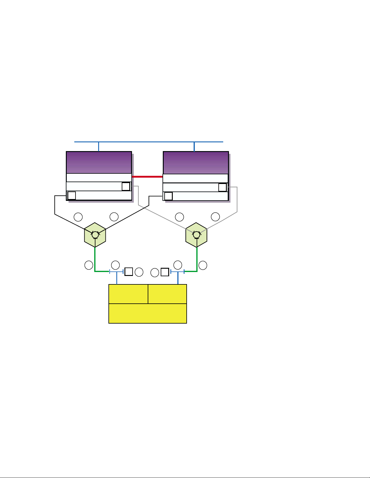
Figure 3–7: TruCluster Server Configuration with HSZ70 in Multiple-Bus
Failover Mode
Network
Member
System
1
Memory Channel
KZPBA-CB (ID 6)
KZPBA-CB (ID 6)
T
1
T
2
1
T
DS-DWZZH-03
T
3
Controller A Controller B
Memory
Channel
Interface
T
4
T
StorageWorks
RAID Array 7000
Member
System
2
Memory Channel
KZPBA-CB (ID 7)
KZPBA-CB (ID 7)
T
1
T
T
T
3
4
T
HSZ70HSZ70
2
T
1
DS-DWZZH-03
ZK-1601U-AI
Table 3–4 shows the components used to create the cluster shown in
Figure 3–7.
Figure 3–8 shows a two-member TruCluster Server configuration with
a radially connected dual-redundant HSZ80 configured for multiple-bus
failover.
3–24 Shared SCSI Bus Requirements and Configurations Using UltraSCSI Hardware
Page 77

Figure 3–8: TruCluster Server Configuration with HSZ80 in Multiple-Bus
Failover Mode
Networks
Member System 1
Memory Channel (mca1)
Memory Channel (mca0)
KZPBA-CB (ID 6)
KZPBA-CB (ID 6)
T
1
T
1
T
DS-DWZZH-03
T
2
Port 1
T
4
3
T
Port 2
Controller A
HSZ80
StorageWorks
RAID Array 8000
Memory
Channel
Interfaces
4
T
Port 1
Member System 2
Memory Channel (mca1)
Memory Channel (mca0)
KZPBA-CB (ID 7)
KZPBA-CB (ID 7)
T
1
T
3
Controller B
HSZ80
2
Port 2
T
1
T
DS-DWZZH-03
T
ZK-1602U-AI
Table 3–4 shows the components used to create the cluster shown in
Figure 3–8.
Shared SCSI Bus Requirements and Configurations Using UltraSCSI Hardware 3–25
Page 78

Page 79

4
TruCluster Server System Configuration
Using UltraSCSI Hardware
This chapter describes how to prepare systems for a TruCluster Server
cluster, using UltraSCSI hardware and the preferred method of radial
configuration, including how to connect devices to a shared SCSI bus for
the TruCluster Server product. This chapter does not provide detailed
information about installing devices; it describes only how to set up the
hardware in the context of the TruCluster Server product. Therefore, you
must have the documentation that describes how to install the individual
pieces of hardware. This documentation should arrive with the hardware.
All systems in the cluster must be connected via the Memory Channel cluster
interconnect. Not all members must be connected to a shared SCSI bus.
You need to allocate disks for the following uses:
• One or more disks to hold the Tru64 UNIX operating system. The disk(s)
are either private disk(s) on the system that will become the first cluster
member, or disk(s) on a shared bus that the system can access.
• One or more disks on a shared SCSI bus to hold the clusterwide root (
/usr, and /var AdvFS file systems.
• One disk per member, normally on a shared SCSI bus, to hold member
boot partitions.
• Optionally, one disk on a shared SCSI bus to act as the quorum disk. See
Section 1.4.1.4, and for a more detailed discussion of the quorum disk,
see the TruCluster Server
All configurations covered in this manual assume the use of a shared SCSI
bus.
______________________ Note _______________________
If you are using Fibre Channel storage, see Chapter 6.
Before you connect devices to a shared SCSI bus, you must:
• Plan your hardware configuration, determining which devices will be
connected to each shared SCSI bus, which devices will be connected
together, and which devices will be at the ends of each bus.
TruCluster Server System Configuration Using UltraSCSI Hardware 4–1
Cluster Administration manual.
/),
Page 80

This is especially critical if you will install tape devices on the shared
SCSI bus. With the exception of the TZ885, TZ887, TL890, TL891, and
TL892, tape devices can only be installed at the end of a shared SCSI
bus. These tape devices are the only supported tape devices that can
be terminated externally.
• Place the devices as close together as possible and ensure that shared
SCSI buses will be within length limitations.
• Prepare the systems and storage shelves for the appropriate bus
connection, including installing SCSI controllers, UltraSCSI hubs,
trilink connectors, and SCSI signal converters.
After you install all necessary cluster hardware and connect the shared
SCSI buses, be sure that the systems can recognize and access all the shared
disks (see Section 4.3.2). You can then install the TruCluster Server software
as described in the TruCluster Server
Software Installation manual.
4.1 Planning Your TruCluster Server Hardware
Configuration
Before you set up a TruCluster Server hardware configuration, you must
plan a configuration to meet your performance and availability needs. You
must determine the following components for your configuration:
• Number and type of member systems and the number of shared SCSI
buses
You can use two to eight member systems for TruCluster Server. A
greater number of member systems connected to shared SCSI buses
gives you better application performance and more availability. However,
all the systems compete for the same buses to service I/O requests, so a
greater number of systems decreases I/O performance.
Each member system must have a supported SCSI adapter for each
shared SCSI bus connection. There must be enough PCI slots for the
Memory Channel cluster interconnect(s) and SCSI adapters. The number
of available PCI slots depends on the type of AlphaServer system.
• Cluster interconnects
You need only one cluster interconnect in a cluster. For TruCluster
Server Version 5.0A, the cluster interconnect is the Memory Channel.
However, you can use redundant cluster interconnects to protect against
an interconnect failure and for easier hardware maintenance. If you
have more than two member systems, you must have one Memory
Channel hub for each interconnect.
4–2 TruCluster Server System Configuration Using UltraSCSI Hardware
Page 81

• Number of shared SCSI buses and the storage on each shared bus
Using shared SCSI buses increases storage availability. You can connect
32 shared SCSI buses to a cluster member. You can use any combination
of KZPSA-BB, KZPBA-CB, or KGPSA-BC/CA host bus adapters.
In addition, RAID array controllers allow you to increase your storage
capacity and protect against disk, controller, host bus adapter, and SCSI
bus failures. Mirroring data across shared buses provides you with more
reliable and available data. You can use Logical Storage Manager (LSM)
host-based mirroring for all storage except the clusterwide root (
/) file
system, the member-specific boot disks, and the swap and quorum disk.
• No single-point-of-failure (NSPOF) TruCluster Server cluster
You can use mirroring and multiple-bus failover with the HSZ70, HSZ80,
and HSG80 RAID array controllers to create a NSPOF TruCluster Server
cluster (providing the rest of the hardware is installed).
• Tape loaders on a shared SCSI bus
Because of the length of the internal SCSI cables in some tape
loaders (up to 3 meters), they cannot be externally terminated with a
trilink/terminator combination. Therefore, in general, with the exception
of the TL890, TL891, and TL892, tape loaders must be on the end of the
shared SCSI bus. See Chapter 8 for information on configuring tape
devices on a shared SCSI bus.
• You cannot use Prestoserve in a TruCluster Server cluster to cache I/O
operations for any storage device, regardless of whether it is located
on a shared bus or a bus local to a given system. Because data in
the Prestoserve buffer cache of one member is not accessible to other
member systems, TruCluster Server cannot provide correct failover when
Prestoserve is being used.
Table 4–1 describes how to maximize performance, availability, and
storage capacity in your TruCluster Server hardware configuration. For
example, if you want greater application performance without decreasing
I/O performance, you can increase the number of member systems or you
can set up additional shared storage.
Table 4–1: Planning Your Configuration
To increase: You can:
Application performance Increase the number of member systems.
I/O performance Increase the number of shared buses.
Member system availability Increase the number of member systems.
Cluster interconnect availability Use redundant cluster interconnects.
TruCluster Server System Configuration Using UltraSCSI Hardware 4–3
Page 82

Table 4–1: Planning Your Configuration (cont.)
To increase: You can:
Disk availability Mirror disks across shared buses.
Use a RAID array controller.
Shared storage capacity Increase the number of shared buses.
Use a RAID array controller.
Increase disk size.
4.2 Obtaining the Firmware Release Notes
You may be required to update the system or SCSI controller firmware
during a TruCluster Server installation, so you may need the firmware
release notes.
You can obtain the firmware release notes from:
• The Web at the following URL:
http://www.compaq.com/support/
Select Alpha Systems from the downloadable drivers &
utilities menu. Then select the appropriate system.
• The current Alpha Systems Firmware Update CD-ROM.
_____________________ Note _____________________
To obtain the firmware release notes from the Firmware
Update Utility CD-ROM, your kernel must be configured for
the ISO 9660 Compact Disk File System (CDFS).
To obtain the release notes for the firmware update, follow these steps:
1. At the console prompt, or using the system startup log if the Tru64
UNIX operating system is running, determine the drive number of
the CD-ROM.
2. Boot the Tru64 UNIX operating system if it is not already running.
3. Log in as root.
4. Place the Alpha Systems Firmware Update CD-ROM applicable to
the Tru64 UNIX version installed (or to be installed) into the drive.
5. Mount the CD-ROM as follows (/dev/disk/cdrom0c is used as an
example CD-ROM drive):
# mount -rt cdfs -o noversion /dev/disk/cdrom0cc /mnt
4–4 TruCluster Server System Configuration Using UltraSCSI Hardware
Page 83

6. Copy the appropriate release notes to your system disk. In this
example, obtain the firmware release notes for the AlphaServer
DS20 from the Version 5.6 Alpha Firmware Update CD-ROM:
# cp /mnt/doc/ds20_v56_fw_relnote.txt ds20-rel-notes
7. Unmount the CD-ROM drive:
# umount /mnt
8. Print the release notes.
4.3 TruCluster Server Hardware Installation
Member systems may be connected to a shared SCSI bus with a peripheral
component interconnect (PCI) SCSI adapter. Before you install a PCI SCSI
adapter into a PCI slot on a member system, ensure that the module is at
the correct hardware revision.
The qualification and use of the DS-DWZZH-series UltraSCSI hubs in
TruCluster Server clusters allows the PCI host bus adapters to be cabled
into a cluster in two different ways:
• Preferred method with radial connection to a DWZZH UltraSCSI hub
and internal termination: The PCI host bus adapter internal termination
resistor SIPs are not removed. The host bus adapters and storage
subsystems are connected directly to a DWZZH UltraSCSI hub port.
There can be only one member system connected to a hub port.
The use of a DWZZH UltraSCSI hub in a TruCluster Server cluster is
preferred because it improves the reliability to detect cable faults.
• Old method with external termination: Shared SCSI bus termination is
external to the PCI host adapters. This is the old method used to connect
a PCI host adapter to the cluster; remove the adapter termination
resistor SIPs and install a Y cable and an H879-AA terminator for
external termination. This allows the removal of a SCSI bus cable from
the host adapter without affecting SCSI bus termination.
This method (discussd in Chapter 9 and Chapter 10) may be used with or
without a DWZZH UltraSCSI hub. When used with an UltraSCSI hub,
there may be more than one member system on a SCSI bus segment
attached to a DS-DWZZH-03 hub port.
The following sections describe how to install the KZPBA-CB
PCI-to-UltraSCSI differential host adapter and configure them into
TruCluster Server clusters using the preferred method of radial connection
with internal termination.
TruCluster Server System Configuration Using UltraSCSI Hardware 4–5
Page 84

______________________ Note _______________________
The KZPSA-BB can be used in any configuration in place of the
KZPBA-CB. The use of the KZPSA-BB is not mentioned in this
chapter because it is not UltraSCSI hardware, and it cannot
operate at UltraSCSI speeds.
The use of the KZPSA-BB (and the KZPBA-CB) with external termination is
covered in Chapter 10.
It is assumed that when you start to install the hardware necessary to create
a TruCluster Server configuration, you have sufficient storage to install the
TruCluster Server software, and that you have set up any RAID storagesets.
Follow the steps in Table 4–2 to start the procedure for TruCluster Server
hardware installation. You can save time by installing the Memory Channel
adapters, redundant network adapters (if applicable), and KZPBA-CB SCSI
adapters all at the same time.
Follow the directions in the referenced documentation, or the steps in
the referenced tables, returning to the appropriate table when you have
completed the steps in the referenced table.
_____________________ Caution _____________________
Static electricity can damage modules and electronic components.
We recommend using a grounded antistatic wrist strap and a
grounded work surface when handling modules.
Table 4–2: Configuring TruCluster Server Hardware
Action Refer to:
Step
1
Install the Memory Channel module(s),
cables, and hub(s) (if a hub is required).
2
Install Ethernet or FDDI network
adapters.
Install ATM adapters if using ATM. Chapter 7 and ATMworks 350
3
Install a KZPBA-CB UltraSCSI adapter
for each radially connected shared SCSI
bus in each member system.
4–6 TruCluster Server System Configuration Using UltraSCSI Hardware
Chapter 5
User’s guide for the applicable
Ethernet or FDDI adapter,
and the user’s guide for the
applicable system
Adapter Installation and Service
Section 4.3.1 and Table 4–3
a
Page 85

Table 4–2: Configuring TruCluster Server Hardware (cont.)
Action Refer to:
Step
4
Update the system SRM console
firmware from the latest Alpha Systems
Firmware Update CD-ROM.
Use the firmware update release
notes (Section 4.2)
______________________ Note _____________________
The SRM console firmware includes the ISP1020/1040-based PCI
option firmware, which includes the KZPBA-CB. When you update the
SRM console firmware, you are enabling the KZPBA-CB firmware to
be updated. On a powerup reset, the SRM console loads KZPBA-CB
adapter firmware from the console system flash ROM into NVRAM for
all Qlogic ISP1020/1040-based PCI options, including the KZPBA-CB
PCI-to-Ultra SCSI adapter.
a
If you install additional KZPBA-CB SCSI adapters or an extra network adapter atthis time, delay testing
the Memory Channel until you have installed all of the hardware.
4.3.1 Installation of a KZPBA-CB Using Internal Termination for a
Radial Configuration
Use this method of cabling member systems and shared storage in a
TruCluster Server cluster if you are using a DWZZH UltraSCSI hub. You
must reserve at least one hub port for shared storage.
The DWZZH-series UltraSCSI hubs are designed to allow more separation
between member systems and shared storage. Using the UltraSCSI hub also
improves the reliability of the detection of cable faults.
A side benefit is the ability to connect the member systems’ SCSI adapter
directly to a hub port without external termination. This simplifies the
configuration by reducing the number of cable connections.
A DWZZH UltraSCSI hub can be installed in:
• A StorageWorks UltraSCSI BA356 shelf that has the required 180-watt
power supply.
• The lower righthand device slot of the BA370 shelf within the RA7000
or ESA 10000 RAID array subsystems. This position minimizes cable
lengths and interference with disks.
• A non-UltraSCSI BA356 that has been upgraded to the 180-watt power
supply with the DS-BA35X-HH option.
An UltraSCSI hub only receives power and mechanical support from the
storage shelf. There is no SCSI bus continuity between the DWZZH and
storage shelf.
TruCluster Server System Configuration Using UltraSCSI Hardware 4–7
Page 86

The DWZZH contains a differential to single-ended signal converter for each
hub port (sometimes referred to as a DWZZA on a chip, or DOC chip). The
single-ended sides are connected together to form an internal single-ended
SCSI bus segment. Each differential SCSI bus port is terminated internal to
the DWZZH with terminators that cannot be disabled or removed.
Power for the DWZZH termination (termpwr) is supplied by the host SCSI
bus adapter or RAID array controller connected to the DWZZH port. If the
member system or RAID array controller is powered down, or the cable is
removed from the KZPBA-CB, RAID array controller,or hub port, the loss of
termpwr disables the hub port without affecting the remaining hub ports
or SCSI bus segments. This is similar to removing a Y cable when using
external termination.
______________________ Note _______________________
The UltraSCSI BA356 DS-BA35X-DA personality module does not
generate termpwr. Therefore, you cannot connect an UltraSCSI
BA356 directly to a DWZZH hub. The use of the UltraSCSI
BA356 in a TruCluster Server cluster is discussed in Chapter 9.
The other end of the SCSI bus segment is terminated by the KZPBA-CB
onboard termination resistor SIPs, or by a trilink connector/terminator
combination installed on the RAID array controller.
The KZPBA-CB UltraSCSI host adapter:
• Is a high-performance PCI option connecting the PCI-based host system
to the devices on a 16-bit, ultrawide differential SCSI bus.
• Is installed in a PCI slot of the supported member system.
• Is a single-channel, ultrawide differential adapter.
• Operates at the following speeds:
– 5 MB/sec narrow SCSI at slow speed
– 10 MB/sec narrow SCSI at fast speed
– 20 MB/sec wide differential SCSI
– 40 MB/sec wide differential UltraSCSI
______________________ Note _______________________
Even though the KZPBA-CB is an UltraSCSI device, it has an
HD68 connector.
4–8 TruCluster Server System Configuration Using UltraSCSI Hardware
Page 87

Your storage shelves or RAID array subsystems should be set up before
completing this portion of an installation.
Use the steps in Table 4–3 to set up a KZPBA-CB for a TruCluster Server
cluster that uses radial connection to a DWZZH UltraSCSI hub.
Table 4–3: Installing the KZPBA-CB for Radial Connection to a DWZZH
UltraSCSI Hub
Action Refer to:
Step
1
Ensure that the eight KZPBA-CB internal
termination resistor SIPs, RM1-RM8 are installed.
2
Power down the system. Install a KZPBA-CB
PCI-to-UltraSCSI differential host adapter in
the PCI slot corresponding to the logical bus to
be used for the shared SCSI bus. Ensure that
the number of adapters are within limits for the
system, and that the placement is acceptable.
3
Install a BN38C cable between the KZPBA-CB
UltraSCSI host adapter and a DWZZH port.
Section4.3.1,Figure4–1,
and KZPBA-CB
PCI-to-Ultra SCSI
DifferentialHostAdapter
User’s Guide
TruCluster Server
Cluster Administration,
Section 2.4.2, and
KZPBA-CB PCI-to-Ultra
SCSI Differential Host
Adapter User’s Guide
_____________________ Notes _____________________
The maximum length of a SCSI bus segment is 25 meters, including the
bus length internal to the adapter and storage devices.
One end of the BN38C cable is 68-pin high density. The other end is
68-pin VHDCI. The DWZZH accepts the 68-pin VHDCI connector.
The number of member systems in the cluster has to be one less than
the number of DWZZH ports.
4
Power up the system and use the show config
and show device console commands to display
the installed devices and information about
the KZPBA-CBs on the AlphaServer systems.
Look for QLogic ISP1020 in the show config
display and isp in the show device display to
determine which devices are KZPBA-CBs.
5
Use the show pk* or show isp* console
commands to determine the KZPBA-CB SCSI
bus ID, and then use the set console command
to set the SCSI bus ID.
TruCluster Server System Configuration Using UltraSCSI Hardware 4–9
Section 4.3.2 and
Example 4–1 through
Example 4–4
Section 4.3.3 and
Example 4–5 through
Example 4–7
Page 88

Table 4–3: Installing the KZPBA-CB for Radial Connection to a DWZZH
UltraSCSI Hub (cont.)
Action Refer to:
Step
_____________________ Notes _____________________
Ensure that the SCSI ID that you use is distinct from all other SCSI IDs
on the same shared SCSI bus. If you do not remember the other SCSI
IDs, or do not have them recorded, you must determine these SCSI IDs.
If you are using a DS-DWZZH-05, you cannot use SCSI ID 7
for a KZPBA-CB UltraSCSI adapter; SCSI ID 7 is reserved for
DS-DWZZH-05 use.
If you are using a DS-DWZZH-05 and fair arbitration is enabled, you
must use the SCSI ID assigned to the hub port the adapter is connected
to.
You will have problems if you have two or more SCSI adapters at the
same SCSI ID on any one SCSI bus.
6
Repeat steps 1 through 6 for any other
KZPBA-CBs to be installed on this shared SCSI
bus on other member systems.
7
Connect a DS-DWZZH-03 or DS-DWZZH-05
UltraSCSI hub to an:
HSZ70 or HSZ80 in transparent failover mode Section 3.7.1.1
HSZ70 or HSZ80 in multiple-bus failover mode Section 3.7.1.2
Section 3.6
4.3.2 Displaying KZPBA-CB Adapters with the show Console
Commands
Use the show config and show device console commands to display
system configuration. Use the output to determine which devices are
KZPBA-CBs, and to determine their SCSI bus IDs.
Example 4–1 shows the output from the show config console command on
an AlphaServer DS20 system.
Example 4–1: Displaying Configuration on an AlphaServer DS20
P00>>> show config
SRM Console: T5.4-15
PALcode: OpenVMS PALcode V1.54-43, Tru64 UNIX PALcode V1.49-45
Processors
CPU 0 Alpha 21264-4 500 MHz SROM Revision: V1.82
Bcache size: 4 MB
CPU 1 Alpha 21264-4 500 MHz SROM Revision: V1.82
Bcache size: 4 MB
4–10 TruCluster Server System Configuration Using UltraSCSI Hardware
AlphaServer DS20 500 MHz
Page 89

Example 4–1: Displaying Configuration on an AlphaServer DS20 (cont.)
Core Logic
Cchip DECchip 21272-CA Rev 2.1
Dchip DECchip 21272-DA Rev 2.0
Pchip 0 DECchip 21272-EA Rev 2.2
Pchip 1 DECchip 21272-EA Rev 2.2
TIG Rev 4.14
Arbiter Rev 2.10 (0x1)
MEMORY
Array # Size Base Addr
------- ---------- ---------
0 512 MB 000000000
Total Bad Pages = 0
Total Good Memory = 512 MBytes
PCI Hose 00
Bus 00 Slot 05/0: Cypress 82C693
Bus 00 Slot 05/1: Cypress 82C693 IDE
Bus 00 Slot 05/2: Cypress 82C693 IDE
Bus 00 Slot 05/3: Cypress 82C693 USB
Bus 00 Slot 07: DECchip 21152-AA
Bus 00 Slot 08: QLogic ISP1020
Bus 00 Slot 09: QLogic ISP1020
Bus 02 Slot 00: NCR 53C875
Bus 02 Slot 01: NCR 53C875
dqa.0.0.105.0
dqb.0.1.205.0
pkc0.7.0.8.0 SCSI Bus ID 7
dkc0.0.0.8.0 HSZ70
dkc1.0.0.8.0 HSZ70
dkc100.1.0.8.0 HSZ70
dkc101.1.0.8.0 HSZ70CCL
dkc2.0.0.8.0 HSZ70
dkc3.0.0.8.0 HSZ70
dkc4.0.0.8.0 HSZ70
dkc5.0.0.8.0 HSZ70
dkc6.0.0.8.0 HSZ70
dkc7.0.0.8.0 HSZ70
pkd0.7.0.9.0 SCSI Bus ID 7
dkd0.0.0.9.0 HSZ40
dkd1.0.0.9.0 HSZ40
dkd100.1.0.9.0 HSZ40
dkd101.1.0.9.0 HSZ40
dkd102.1.0.9.0 HSZ40
.
.
.
dkd5.0.0.9.0 HSZ40
dkd6.0.0.9.0 HSZ40
dkd7.0.0.9.0 HSZ40
pka0.7.0.2000.0 SCSI Bus ID 7
dka0.0.0.2000.0 RZ1CB-CS
dka100.1.0.2000.0 RZ1CB-CS
dka200.2.0.2000.0 RZ1CB-CS
dka500.5.0.2000.0 RRD46
pkb0.7.0.2001.0 SCSI Bus ID 7
Bridge to Bus 1, ISA
Bridge to Bus 2, PCI
TruCluster Server System Configuration Using UltraSCSI Hardware 4–11
Page 90

Example 4–1: Displaying Configuration on an AlphaServer DS20 (cont.)
Bus 02 Slot 02: DE500-AA Network Controller
PCI Hose 01
Bus 00 Slot 07: DEC PCI FDDI
Bus 00 Slot 08: DEC PCI MC
Bus 00 Slot 09: DEC PCI MC
ISA
Slot Device Name Type Enabled BaseAddr IRQ DMA
0
0 MOUSE Embedded Yes 60 12
1 KBD Embedded Yes 60 1
2 COM1 Embedded Yes 3f8 4
3 COM2 Embedded Yes 2f8 3
4 LPT1 Embedded Yes 3bc 7
5 FLOPPY Embedded Yes 3f0 6 2
ewa0.0.0.2002.0 00-06-2B-00-0A-48
fwa0.0.0.7.1 08-00-2B-B9-0D-5D
Rev: 22, mca0
Rev: 22, mcb0
Example 4–2 shows the output from the show device console command
entered on an AlphaServer DS20 system.
Example 4–2: Displaying Devices on an AlphaServer DS20
P00>>> show device
dka0.0.0.2000.0 DKA0 RZ1CB-CS 0656
dka100.1.0.2000.0 DKA100 RZ1CB-CS 0656
dka200.2.0.2000.0 DKA200 RZ1CB-CS 0656
dka500.5.0.2000.0 DKA500 RRD46 1337
dkc0.0.0.8.0 DKC0 HSZ70 V71Z
dkc1.0.0.8.0 DKC1 HSZ70 V71Z
.
.
.
dkc7.0.0.8.0 DKC7 HSZ70 V71Z
dkd0.0.0.9.0 DKD0 HSZ40 YA03
dkd1.0.0.9.0 DKD1 HSZ40 YA03
dkd100.1.0.9.0 DKD100 HSZ40 YA03
dkd101.1.0.9.0 DKD101 HSZ40 YA03
dkd102.1.0.9.0 DKD102 HSZ40 YA03
.
.
.
dkd7.0.0.9.0 DKD7 HSZ40 YA03
dva0.0.0.0.0 DVA0
ewa0.0.0.2002.0 EWA0 00-06-2B-00-0A-48
fwa0.0.0.7.1 FWA0 08-00-2B-B9-0D-5D
pka0.7.0.2000.0 PKA0 SCSI Bus ID 7
pkb0.7.0.2001.0 PKB0 SCSI Bus ID 7
pkc0.7.0.8.0 PKC0 SCSI Bus ID 7 5.57
pkd0.7.0.9.0 PKD0 SCSI Bus ID 7 5.57
4–12 TruCluster Server System Configuration Using UltraSCSI Hardware
Page 91

Example 4–3 shows the output from the show config console command
entered on an AlphaServer 8200 system.
Example 4–3: Displaying Configuration on an AlphaServer 8200
>>> show config
Name Type Rev Mnemonic
TLSB
4++ KN7CC-AB 8014 0000 kn7cc-ab0
5+ MS7CC 5000 0000 ms7cc0
8+ KFTIA 2020 0000 kftia0
C0 Internal PCI connected to kftia0 pci0
0+ QLogic ISP1020 10201077 0001 isp0
1+ QLogic ISP1020 10201077 0001 isp1
2+ DECchip 21040-AA 21011 0023 tulip0
4+ QLogic ISP1020 10201077 0001 isp2
5+ QLogic ISP1020 10201077 0001 isp3
6+ DECchip 21040-AA 21011 0023 tulip1
C1 PCI connected to kftia0
0+ KZPAA 11000 0001 kzpaa0
1+ QLogic ISP1020 10201077 0005 isp4
2+ KZPSA 81011 0000 kzpsa0
3+ KZPSA 81011 0000 kzpsa1
4+ KZPSA 81011 0000 kzpsa2
7+ DEC PCI MC 181011 000B mc0
Example 4–4 shows the output from the show device console command
entered on an AlphaServer 8200 system.
Example 4–4: Displaying Devices on an AlphaServer 8200
>>> show device
polling for units on isp0, slot0, bus0, hose0...
polling for units on isp1, slot1, bus0, hose0...
polling for units on isp2, slot4, bus0, hose0...
polling for units on isp3, slot5, bus0, hose0...
polling for units kzpaa0, slot0, bus0, hose1...
pke0.7.0.0.1 kzpaa4 SCSI Bus ID 7
dke0.0.0.0.1 DKE0 RZ28 442D
dke200.2.0.0.1 DKE200 RZ28 442D
dke400.4.0.0.1 DKE400 RRD43 0064
polling for units isp4, slot1, bus0, hose1...
dkf0.0.0.1.1 DKF0 HSZ70 V70Z
dkf1.0.0.1.1 DKF1 HSZ70 V70Z
dkf2.0.0.1.1 DKF2 HSZ70 V70Z
dkf3.0.0.1.1 DKF3 HSZ70 V70Z
TruCluster Server System Configuration Using UltraSCSI Hardware 4–13
Page 92

Example 4–4: Displaying Devices on an AlphaServer 8200 (cont.)
dkf4.0.0.1.1 DKF4 HSZ70 V70Z
dkf5.0.0.1.1 DKF5 HSZ70 V70Z
dkf6.0.0.1.1 DKF6 HSZ70 V70Z
dkf100.1.0.1.1 DKF100 RZ28M 0568
dkf200.2.0.1.1 DKF200 RZ28M 0568
dkf300.3.0.1.1 DKF300 RZ28 442D
polling for units on kzpsa0, slot 2, bus 0, hose1...
kzpsa0.4.0.2.1 dkg TPwr 1 Fast 1 Bus ID 7 L01 A11
dkg0.0.0.2.1 DKG0 HSZ50-AX X29Z
dkg1.0.0.2.1 DKG1 HSZ50-AX X29Z
dkg2.0.0.2.1 DKG2 HSZ50-AX X29Z
dkg100.1.0.2.1 DKG100 RZ26N 0568
dkg200.2.0.2.1 DKG200 RZ28 392A
dkg300.3.0.2.1 DKG300 RZ26N 0568
polling for units on kzpsa1, slot 3, bus 0, hose1...
kzpsa1.4.0.3.1 dkh TPwr 1 Fast 1 Bus ID 7 L01 A11
dkh100.1.0.3.1 DKH100 RZ28 442D
dkh200.2.0.3.1 DKH200 RZ26 392A
dkh300.3.0.3.1 DKH300 RZ26L 442D
polling for units on kzpsa2, slot 4, bus 0, hose1...
kzpsa2.4.0.4.1 dki TPwr 1 Fast 1 Bus ID 7 L01 A10
dki100.1.0.3.1 DKI100 RZ26 392A
dki200.2.0.3.1 DKI200 RZ28 442C
dki300.3.0.3.1 DKI300 RZ26 392A
4.3.3 Displaying Console Environment Variables and Setting the
KZPBA-CB SCSI ID
The following sections show how to use the show console command to display
the pk* and isp* console environment variables, and set the KZPBA-CB
SCSI ID on various AlphaServer systems. Use these examples as guides
for your system.
Note that the console environment variables used for the SCSI options vary
from system to system. Also, a class of environment variables (for example,
pk* or isp*) may show both internal and external options.
Compare the following examples with the devices shown in the show
config and show dev examples to determine which devices are KZPSA-BBs
or KZPBA-CBs on the shared SCSI bus.
4–14 TruCluster Server System Configuration Using UltraSCSI Hardware
Page 93

4.3.3.1 Displaying KZPBA-CB pk* or isp* Console Environment Variables
To determine the console environment variables to use, execute the show
pk* and show isp* console commands.
Example 4–5 shows the pk console environment variables for an AlphaServer
DS20.
Example 4–5: Displaying the pk* Console Environment Variables on an
AlphaServer DS20 System
P00>>>show pk*
pka0_disconnect 1
pka0_fast 1
pka0_host_id 7
pkb0_disconnect 1
pkb0_fast 1
pkb0_host_id 7
pkc0_host_id 7
pkc0_soft_term on
pkd0_host_id 7
pkd0_soft_term on
Comparing the show pk* command display in Example 4–5 with the
show config command in Example 4–1, you determine that the first two
devices shown in Example 4–5, pkao and pkb0 are for NCR 53C875 SCSI
controllers. The next two devices, pkc0 and pkd0, shown in Example 4–1as
Qlogic ISP1020 devices, are KZPBA-CBs, which are really Qlogic ISP1040
devices (regardless of what the console says).
Our interest then, is in pkc0 and pkd0.
Example 4–5 shows two pk*0_soft_term environment variables,
pkc0_soft_term and pkd0_soft_term, both of which are on.
The pk*0_soft_term environment variable applies to systems using the
QLogic ISP1020 SCSI controller, which implements the 16-bit wide SCSI
bus and uses dynamic termination.
The QLogic ISP1020 module has two terminators, one for the 8 low bits and
one for the high 8 bits. There are five possible values for pk*0_soft_term:
• off — Turns off both low 8 bits and high 8 bits
• low — Turns on low 8 bits and turns off high 8 bits
• high — Turns on high 8 bits and turns off low 8 bits
TruCluster Server System Configuration Using UltraSCSI Hardware 4–15
Page 94

• on — Turns on both low 8 bits and high 8 bits
• diff — Places the bus in differential mode
The KZPBA-CB is a Qlogic ISP1040 module, and its termination is
determined by the presence or absence of internal termination resistor SIPs
RM1-RM8. Therefore, the pk*0_soft_term environment variable has no
meaning and it may be ignored.
Example 4–6 shows the use of the show isp console command to display
the console environment variables for KZPBA-CBs on an AlphaServer 8x00.
Example 4–6: Displaying Console Variables for a KZPBA-CB on an
AlphaServer 8x00 System
P00>>>show isp*
isp0_host_id 7
isp0_soft_term on
isp1_host_id 7
isp1_soft_term on
isp2_host_id 7
isp2_soft_term on
isp3_host_id 7
isp3_soft_term on
isp5_host_id 7
isp5_soft_term diff
Both Example 4–3 and Example 4–4 show five isp devices; isp0, isp1,
isp2, isp3, and isp4. In Example 4–6, the show isp* console command
shows isp0, isp1, isp2, isp3, and isp5.
The console code that assigns console environment variables counts every I/O
adapter including the KZPAA, which is the device after isp3, and therefore
logically isp4 in the numbering scheme. The show isp console command
skips over isp4 because the KZPAA is not a QLogic 1020/1040 class module.
Example 4–3 and Example 4–4 show that isp0, isp1, isp2, and isp3
are devices on the internal KFTIA PCI bus and not on a shared SCSI bus.
Only isp4, the KZPBA-CB, is on a shared SCSI bus (and the show isp
console command displays it as isp5). The other three shared SCSI buses
use KZPSA-BBs (Use the show pk* console command to display the KZPSA
console environment variables.)
4–16 TruCluster Server System Configuration Using UltraSCSI Hardware
Page 95

4.3.3.2 Setting the KZPBA-CB SCSI ID
After you determine the console environment variables for the KZPBA-CBs
on the shared SCSI bus, use the set console command to set the SCSI
ID. For a TruCluster Server cluster, you will most likely have to set the
SCSI ID for all KZPBA-CB UltraSCSI adapters except one. And, if you are
using a DS-DWZZH-05, you will have to set the SCSI IDs for all KZPBA-CB
UltraSCSI adapters.
______________________ Notes ______________________
You will have problems if you have two or more SCSI adapters at
the same SCSI ID on any one SCSI bus.
If you are using a DS-DWZZH-05, you cannot use SCSI ID 7
for a KZPBA-CB UltraSCSI adapter; SCSI ID 7 is reserved for
DS-DWZZH-05 use.
If DS-DWZZH-05 fair arbitration is enabled, The SCSI ID of the
host adapter must match the SCSI ID assigned to the hub port.
Mismatching or duplicating SCSI IDs will cause the hub to hang.
SCSI ID 7 is reserved for the DS-DWZZH-05 whether fair arbitration is
enabled or not.
Use the set console command as shown in Example 4–7 to set the SCSI ID.
In this example, the SCSI ID is set for KZPBA-CB pkc on the AlphaServer
DS20 shown in Example 4–5.
Example 4–7: Setting the KZPBA-CB SCSI Bus ID
P00>>> show pkc0_host_id
7
P00>>> set pkc0_host_id 6
P00>>> show pkc0_host_id
6
4.3.3.3 KZPBA-CB Termination Resistors
The KZPBA-CB internal termination is disabled by removing the
termination resistors RM1-RM8, as shown in Figure 4–1.
TruCluster Server System Configuration Using UltraSCSI Hardware 4–17
Page 96

Figure 4–1: KZPBA-CB Termination Resistors
Internal Narrow Device
Connector P2
JA1
SCSI Bus Termination
Resistors RM1-RM8
Internal Wide Device
Connector J2
ZK-1451U-AI
4–18 TruCluster Server System Configuration Using UltraSCSI Hardware
Page 97

5
Setting Up the Memory Channel Cluster
Interconnect
This chapter describes Memory Channel configuration restrictions, and
describes how to set up the Memory Channel cluster interconnect, including
setting up a Memory Channel hub, Memory Channel optical converter (MC2
only), and connecting link cables.
Two versions of the Memory Channel PCI adapter are available; CCMAA
and CCMAB (MC2).
Two variations of the CCMAA PCI adapter are in use; CCMAA-AA (MC1)
and CCMAA-AB (MC1.5). As the hardware used with these two PCI
adapters is the same, this manual often refers to MC1 when referring to
either of these variations.
See the TruCluster Server Software Product Description (SPD) for a list
of the supported Memory Channel hardware. See the Memory Channel
User’s Guide for illustrations and more detailed information about installing
jumpers, Memory Channel adapters, and hubs.
You can have two Memory Channel adapters with TruCluster Server, but
only one rail can be active at a time. This is referred to as a failover pair. If
the active rail fails, cluster communications fails over to the inactive rail.
See Section 2.2 for a discussion on Memory Channel restrictions.
To set up the Memory Channel interconnects, follow these steps, referring to
the appropriate section and the Memory Channel User’s Guide as necessary:
1. Set the Memory Channel jumpers (Section 5.1).
2. Install the Memory Channel adapter into a PCI slot on each system
(Section 5.2).
3. If you are using fiber optics with MC2, install the CCMFB fiber optics
module (Section 5.3).
4. If you have more than two systems in the cluster, install a Memory
Channel hub (Section 5.4).
5. Connect the Memory Channel cables (Section 5.5).
6. After you complete steps 1 through 5 for all systems in the cluster, apply
power to the systems and run Memory Channel diagnostics (Section 5.6).
Setting Up the Memory Channel Cluster Interconnect 5–1
Page 98

____________________ Note _____________________
If you are installing SCSI or network adapters, you may wish
to complete all hardware installation before powering up the
systems to run Memory Channel diagnostics.
5.1 Setting the Memory Channel Adapter Jumpers
The meaning of the Memory Channel adapter module jumpers depends upon
the version of the Memory Channel module.
5.1.1 MC1 and MC1.5 Jumpers
The MC1 and MC1.5 modules (CCMAA-AA and CCMAA-AB respectively)
have adapter jumpers that designate whether the configuration is using
standard or virtual hub mode. If virtual hub mode is being used, there can
be only two systems. One system must be virtual hub 0 (VH0) and the other
must be virtual hub 1 (VH1).
The Memory Channel adapter should arrive with the jumpers set for
standard hub mode (pins 1 to 2 jumpered). Confirm that the jumpers are
set properly for your configuration. The jumper configurations are shown
as if you were holding the module with the jumpers facing you, with the
module end plate in your left hand. The jumpers are right next to the
factory/maintenance cable connector, and are described in Table 5–1.
Table 5–1: MC1 and MC1.5 Jumper Configuration
If hub mode is: Jumper: Example:
Standard Pins 1 to 2
Virtual: VH0 Pins 2 to 3
Virtual: VH1 None needed; storethejumper on pin1or3
5–2 Setting Up the Memory Channel Cluster Interconnect
12 3
12 3
12 3
Page 99

If you are upgrading from virtual hub mode to standard hub mode (or from
standard hub mode to virtual hub mode), be sure to change the jumpers on
all Memory Channel adapters on the rail.
5.1.2 MC2 Jumpers
The MC2 module (CCMAB) has multiple jumpers. They are numbered right
to left, starting with J1 in the upper righthand corner (as you view the
jumper side of the module with the endplate in your left hand). The leftmost
jumpers are J11 and J10. J11 is above J10.
Most of the jumper settings are straightforward, but the window size
jumper, J3, needs some explanation.
If a CCMAA adapter (MC1 or MC1.5) is installed, 128 MB of address space is
allocated for Memory Channel use. If a CCMAB adapter (MC2) PCI adapter
is installed, the memory space allocation for Memory Channel depends on
the J3 jumper and can be 128 or 512 MB.
If two Memory Channel adapters are used as a failover pair to provide
redundancy, the address space allocated for the logical rail depends on the
smaller window size of the physical adapters.
During a rolling upgrade from an MC1 failover pair to an MC2 failover pair,
the MC2 modules can be jumpered for 128 MB or 512 MB. If jumpered
for 512 MB, the increased address space is not achieved until all MC PCI
adapters have been upgraded and the use of 512 MB is enabled. On one
member system, use the sysconfig command to reconfigure the Memory
Channel kernel subsystem to initiate the use of 512 MB address space. The
configuration change is propagated to the other cluster member systems
by entering the following command:
# /sbin/sysconfig -r rm rm_use_512=1
See the TruCluster Server Cluster Administration manual for more
information on failover pairs.
The MC2 jumpers are described in Table 5–2.
Table 5–2: MC2 Jumper Configuration
Jumper: Description: Example:
J1: Hub Mode Standard: Pins 1 to 2
12 3
Setting Up the Memory Channel Cluster Interconnect 5–3
Page 100

Table 5–2: MC2 Jumper Configuration (cont.)
Jumper: Description: Example:
VH0: Pins 2 to 3
12 3
VH1: None needed;
store the jumper on
pin 1 or pin 3
12 3
J3: Window Size 512 MB: Pins 2 to 3
12 3
128 MB: Pins 1 to 2
12 3
J4: Page Size 8-KB page size (UNIX):
Pins 1 to 2
4-KB page size (not
used): Pins 2 to 3
J5: AlphaServer
8x00 Mode
5–4 Setting Up the Memory Channel Cluster Interconnect
8x00 mode selected:
Pins 1 to 2
8x00 mode not selected:
Pins 2 to 3
a
12 3
12 3
12 3
12 3
 Loading...