

Page 1
User’s Manual
5525B/31/32 Line Matrix Printer
Page 2

READ THIS SOFTWARE LICENSE AGREEMENT BEFORE USING THIS PRINTER
Software License Agreement
CAREFULLY READ THE FOLLOWING TERMS AND
CONDITIONS BEFORE USING THIS PRINTER. USING THIS
PRINTER INDICATES YOUR ACCEPTANCE OF THESE TERMS
AND CONDITIONS. IF YOU DO NOT AGREE TO THESE TERMS
AND CONDITIONS, PROMPTLY RETURN THE PRINTER AND
ALL ACCOMPANYING HARDWARE AND WRITTEN MATERIALS
TO THE PLACE YOU OBTAINED THEM, AND YOUR MONEY
WILL BE REFUNDED.
Definitions.
“Software” shall mean the digitally encoded, machine-readable
data and program. The term “Software Product” includes the
Software resident in the printer and its documentation. The
Software Product is licensed (not sold) to you, and Compaq either
owns or licenses from other vendors who own, all copyright, trade
secret, patent and other proprietary rights in the Software Product.
License.
1. Authorized Use. You agree to accept a non-exclusive license
to use the Software resident in the printer solely for your own
customary business or personal purp ose s.
2. Restrictions.
a. To protect the proprietary rights of Compaq, you agree
to maintain the Software Product and other proprietary
information concerning the typefaces in strict
confidence.
b. You agree not to duplicate or copy the Software
Product.
c. You shall not sublic ense , sell, lea se, or othe rwi se
transfer all or any portion of the Software Product
separate from the printer, without the prior written
consent of Compaq.
d. You may not modify or prepare derivative works of the
Software Product.
e. You may not transmit the Software Product over a
network, by telephone, or electronically using any
means; or reverse engineer, decompile or disassemble
the Software.
f. You agree to keep confidential and use your best
efforts to prevent and protect the contents of the
Software Product from unauthorized disclosure or use.
3. Transfer. You may transfer the Software Product with the
printer, but only if the recipient agrees to accept the terms
and conditions of this Agreement. Your license is
automatically terminated if you transfer the Software Product
and printer.
Limited Software Product Warranty
Compaq warrants that for ninety (90) days after delivery, the
Software will perform in accordance with specifications published
by Compaq. Compaq does not warrant that the Software is free
from all bugs, errors and omissions.
Remedy
Your exclusive remedy and the sole liability of Compaq in
connection with the Software is replacement of defective software
with a copy of the same version and revision level.
Disclaimer of Warrantie s and Limitation of Remedies
1. THE PARTIES AGREE THAT ALL OTHER WARRANTIES,
EXPRESS OR IMPLIED, INCLUDING WARRANTIES OF
FITNESS FOR A PARTICULAR PURPOSE AND
MERCHANTABILITY ARE EXCLUDED.
Compaq does not warrant that the functions contained in the
Software will meet your requirements or that the operation of
the Software will be uninterrupted or error free.
Compaq reserves the right to make changes and/or
improvements in the Software without notice at any time.
2. IN NO EVENT WILL COMPAQ BE LIABLE FOR LOST
PROFITS, LOST DATA, BUSINESS INTERRUPTIONS, OR
ANY OTHER DIRECT, INDIRECT, INCIDENTAL OR
CONSEQUENTIAL DAMAGES ARISING OUT OF THE USE
OF OR INABILITY TO USE THIS PRODUCT, EVEN IF
COMPAQ HAS BEEN ADVISED OF THE POSSIBILITY OF
SUCH DAMAGES, OR ANY DAMAGES CAUSED BY THE
ABUSE OR MANIPULATION OF THE SOFTWARE. SOME
STATES DO NOT ALLOW THE EXCLUSION OR
LIMITATION OF LIABILITY FOR CONSEQUENTIAL OR
INCIDENTAL DAMAGES, SO THE ABOVE LIMITATION
MAY NOT APPLY TO YOU.
3. Compaq will not be liable for any loss or damage caused by
delay in furnishing a Software Product or any other
performance under this Agreement.
4. Our entire liability and your exclusive remedies for our liability
of any kind (including liability for negligence except liability for
personal injury caused solely by our negligence) for the
Software Product covered by this Agreement and all other
performance or nonperformance by us under or related to this
Agreement are limited to the remedies specified by this
Agreement.
5. California law governs this Agreement.
Termination of License Agreement
This License shall continue until terminated. This license may be
terminated by agreement between you and Compaq or by Compaq
If you fail to comply with the terms of this License and such failure
is not corrected within thirty (30) days after notice. When this
License is terminated, you shall return to the place you obtained
them, the printer and all copies of the Software and documentation.
U.S. Government Rest ri cte d R igh ts
Use, duplication or disclosure by the Government is subject to
restrictions as set forth in the Rights in Technical Data and
Computer Software clause at FAR 242.227-7013, subdivision (b)
(3) (ii) or subparagraph (c) (1) (ii), as appropriate. Further use,
duplication or discl osure is su bject to res trictions applicable to
restricted rights software as set forth in FAR 52.227-19 (c) (2).
Acknowledgement of Terms and Conditions
YOU ACKNOWLEDGE THAT YOU HAVE READ THIS
AGREEMENT, UNDERSTAND IT, AND AGREE TO BE BOUND
BY ITS TERMS AND CONDITIONS. NEITHER PARTY SHALL BE
BOUND BY ANY STATEMENT OR REPRESENTATION NOT
CONTAINED IN THIS AGREEMENT. NO CHANGE IN THIS
AGREEMENT IS EFFECTIVE UNLESS WRITTEN AND SIGNED
BY PROPERLY AUTHORIZED REPRESENTATIVES OF EACH
PARTY. BY USING THIS PRINTER, YOU AGREE TO ACCEPT
THE TERMS AND CONDITIONS OF THIS AGREEMENT.
Page 3

5525B/31/32 Line Matrix Printer
User’s Manual
P/N 422721-001
Page 4

Compaq® makes no representations or warranties of any kind regarding
this material, including, but not limited to, implied warranties of
merchantability and fitness for a particular purpose. Compaq shall not
be held responsible for errors contained herein or any omissions from
this material or for any damages, whether direct, indirect, incidental or
consequential, in connection with the furnishing, distribution,
performance or use of this material. The information in this manual is
subject to change without notice.
This document contains proprietary information protected by copyright.
No part of this document may be reproduced, copied, translated or
incorporated in any other material in any form or by any means,
whether manual, graphic, electronic, mechanical or otherwise, without
the prior written consent of Compaq.
COPYRIGHT 1999, COMPAQ COMPUTER CORPORATION
All rights reserved.
Page 5

Table of Contents
1 Introduction.............................................11
Printer Overview..................................................................11
The Printer Family.........................................................11
Conventions in This Manual..........................................12
Warnings and Special Information................................13
Related Documents.......................................................13
Graphics Enhancements...............................................13
Taking Care of Your Printer ..........................................14
Protocols and Emulations .............................................14
2 Setting Up the Printer ............................. 15
Before You Begin ................................................................15
Power Requirements ..........................................................15
Select a Site ........................................................................16
Printer Dimensions ..............................................................17
Printer Component Locations..............................................18
Remove Packing Materials..................................................19
Adjust the Paper Supports ............................................22
Release the Paper Chains (Cabinet Model)..................23
Remove Tags................................................................24
Attach the Output Basket (Pedestal Model)..................26
Connect the Interface and Power Cords .............................27
Cabinet Model...............................................................27
Pedestal Model .............................................................29
Interface Connections ...................................................30
Install Basic Components....................................................31
Attach the Control Panel Overlays................................31
Load the Ribbon............................................................32
Load the Paper..............................................................34
5
Page 6

Table of Contents
Set the Top-of-Form ............................................................38
Procedure .....................................................................38
3 Operating the Printer...............................41
Powering On the Printer ......................................................41
Operating Modes.................................................................41
The Control Panel.................. ...... ....... ...... ....... ...... ..............42
Control Panel Keys .......................................................43
Operational Procedures.. ....... ..............................................47
Reloading Paper ...........................................................47
Unloading Paper ..........................................................55
Replacing the Ribbon....................................................57
Canceling a Print Job....................................................60
4 The Configuration Menus........................61
Configuration Overview .......................................................61
Changing and Saving Parameter Settings....................62
Default and Custom Configurations..............................62
Navigating the Menus ...................................................63
Changing Parameters Example....................................64
Saving Your New Configuration....................................66
Main Menu ....................................................................69
CONFIG. CONTROL...........................................................71
Menu.............................................................................71
ACTIVE EMULATION..........................................................73
EMULATION........................................................................74
PCL-II Emulation...........................................................75
LinePrinter Plus Emulation............................................79
P-Series Emulation .......................................................83
Proprinter XL Emulation ........................... ...... ....... .......87
Epson FX Emulation .....................................................90
IGP/PGL Submenu .......................................................93
IGP/VGL Emulation.....................................................101
MAINT / MISC ...................................................................112
6
Page 7

Table of Contents
Menu...........................................................................112
HOST INTERFACE ..........................................................113
Dataproducts Submenu ..............................................114
Serial Submenu............ ...............................................116
IEEE 1284 Parallel (Bidirectional) Submenu...............120
Ethernet Submenu ...................................................... 121
ETHERNET PARAMETERS ........... ...... ............................122
Menu........ ....... ...... ....... ...... ....................................... .. 122
PRINTER CONTROL .......................................................123
DIAGNOSTICS..................................................................125
RIBBONMINDER...............................................................128
5 Interfaces.............................................. 131
Overview............................................................................131
Dataproducts Long Line Interface .....................................132
Dataproducts Long Line Interface Signals ..................133
IEEE 1284 Parallel Interface .............................................134
Compatibility Mode......................................................134
Nibble Mode................................................................134
Byte Mode...................................................................134
Signals ........................................................................135
Terminating Resistor Configurations...........................138
RS-232 and RS-422 Serial Interfaces ...............................140
RS-232........................................................................140
RS-422........................................................................141
Host System Configuration................................................142
Dataproducts Long Lines Parallel Interface ................142
TCP/IP LAN Configuration ..........................................142
Serial Configuration ...... ...... ....... ...... ...... ....... ...... ....... ..143
Internal Ethernet Adapter Configuration............................144
Ethernet Configuration Using the Printer Front Panel.144
Configuring the Internal Ethernet Adapter for TCP/IP .......146
Host Software..............................................................146
Compiling Host Software.............................................147
7
Page 8

Table of Contents
Computer-aided Configuration with ezsetup
or npconfig ..................................................................151
Configuration Through the Network with ARP ............152
Configuration Through the Network with RARP..........154
Configuration Through the Network with BOOTP.......155
Restoring Factory Defaults..........................................155
Host Configuration ......................................................156
Direct Printing Without Spooler...................................156
Printing Via the Spooler ..............................................158
Custom Interface Scripts.............................................159
BSD UNIX...................................................................160
System V UNIX...........................................................164
npd Pseudo-device Interface ......................................166
Other TCP/IP Methods................................................171
Configuring The Internal Ethernet Adapter For Novell ......172
Host Software .............................................................172
Internal Ethernet Adapter............................................173
Host Configuration ......................................................174
PSERVER Setup (Pre-NetWare 4).............................175
RPRINTER Setup (Pre-NetWare 4)............................177
NetWare 4 Options ............... ....... ...... ....... ...... ....... .....180
Configuring the Internal Ethernet Adapter for Windows ....183
Print Methods Overview..............................................183
TCP/IP Setup..............................................................184
Configuring TCP/IP.....................................................186
Host Configuration ......................................................189
6 Troubleshooting ....................................195
Cleaning Requirements.....................................................195
Exterior Cleaning ........................................................195
Interior Cleaning..........................................................196
Diagnosing Problems ................................................... .....198
Printing a Hex Dump...................................................198
Fault Messages...........................................................200
8
Page 9

Table of Contents
A Printer Specifications ........................... 207
Ribbon Specifications.. ....... ...... ....... ...... ............................207
Paper Specifications..........................................................208
Printer Dimensions ............................................................209
Environmental Characteristics...........................................210
Electrical Characteristics ............................. ....... ...... ....... .. 211
Interfaces............... ...... ....... ...... ....... ...... ............................212
Printing Rates....................................................................212
B Downloading Firmware......................... 213
Loading Flash Memory ......................................................213
C ASCII Character Set............................. 219
D Communication and
Trademark Information ................. .. ... .. .. ....221
Communication Notices.....................................................221
Trademark Acknowledgments...........................................223
9
Page 10

Table of Contents
10
Page 11

1 Introduction
Printer Overview
This chapter provides a general overview of your printer and the
conventions used within this manual.
The Printer Family
The Compaq series of line matrix printers consist of 500, 1000, and
1500 lines per minute (lpm) models packaged in various configurations.
All of the models offer software versatility and the latest refinements in
line matrix printing technology. The print mechanisms are housed in
sound-insulated cabinets which make the printer family among the
quietest printers in the world.
Most line matrix printers have specialized architectures, which enable
the printer to emulate, or behave like, another printer. These
specialized architectures are restricted. Your printer, however, has a
flexible architecture that allows new features and emulations to be
added as they become available.
PCL
with each printer. LinePrinter Plus includes the Epson
Printronix
®
IGP
available as optional upgrades. No matter what emulation is installed,
your printer is easy to use. The message display and lights on the
control panel communicate with you directly and clearly. You can select
every function on your printer at the control panel, or you can send
commands from the host computer.
®
-II is the standard emulation. LinePrinter Plus® is also included
®
P-Series, and IBM Proprinter® III XL emulations. The
/PGL® and IGP/VGL graphics enhancement emulations are
®
FX-1050,
11
Page 12
Chapter 1 Printer Overview
The printer combines the use of Flash, RAM, and nonvolatile RAM for
program execution. The Flash is used for all program, font, and
emulation storage. New fonts, emulations, or program updates can be
downloaded to Flash memory via the parallel or serial interface. The
RAM is used for buffers, print image storage, and execution variables.
The non-volatile RAM stores configuration, statistics, and internal
parameters.
Refer to the following table for a complete listing of model numbers and
options.
Table 1. The Compaq Line Matrix Printer Family
Model
Number
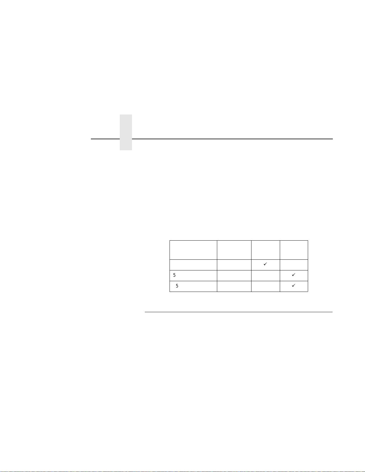
5525B 500 lpm
5531 1000 lpm
5532 1500 lpm
Print Speed Pedestal Cabinet
á
á
á
Conventions in This Manual
All uppercase print indic ate s con tr ol pan el key s .
Example: Press the CLEAR key, then press the ON LINE key.
Quotation marks (“ ”) indicate messages on the Liquid Crystal Display
(LCD).
Example: Press the ON LINE key. “OFFLINE” appears on the LCD.
The + (plus) symbol represents key combinations.
Example: “Press
(DOWN) key at the same time.
= + >” means press the = (UP) key and the >
12
Page 13

Warnings and Special Information
Wa rnings and Special Inform ation
Read and comply with all information highlighted under special
headings:
WARNING
CAUTION
IMPORT ANT
Conditions that can harm you as well as damage the printer.
Conditions that can damage the printer or related equipment.
Information that is vital to the operation of the printer.
NOTE: Information affecting printer operation.
Related Documents
•
Maintenance Manual —
line matrix printer at the field service level of maintenance.
•
LinePrinter Plus Programmer's Reference Manual —
host control codes for the LinePrinter Plus emulations.
•
PCL-II Programmer's Reference Manual —
codes for the Printer Control Language emulation.
•
IGP/PGL Programmer's Reference Manual —
used with the optional IGP Printronix emulation enhancement
feature.
•
IGP/VGL Programmer's Reference Manual —
used with the optional Code V
•
PrintNetTM User’s Manual —
configuration, and operation.
Explains how to maintain and repair the
Covers the
Covers the host control
Provides information
TM
emulation enhancement feature.
Information about network protocols,
Provides information
Graphics Enhancements
The IGP/PGL and IGP/VGL emulations allow you to create and store
forms, generate logos, bar codes, expanded characters, and create
other graphics. Alphanumeric and bar code data are added as the form
is printed. These emulations are available as factory-installed or fieldinstalled options. For more information, contact your authorized service
representative.
13
Page 14

Chapter 1 Printer Overview
Taking Care of Your Printer
Your printer will produce high print quality jobs if it is well taken care of.
Periodic cleaning, handling the printer properly, and using the correct
printer supplies such as paper and ribbons ensures optimum
performance. Chapter 6 explains how to clean the printer, and printer
supplies are listed in Appendix A.
Whenever it is necessary to service the printer, remember these
important maintenance concepts:
• Use only the ribbons specified in Appendix A. Use of incorrect
ribbons can lead to ink migration problems, degraded print quality,
and expensive damage to the printer.
• Incorrect closure of the forms thickness lever can lead to smearing,
degraded print quality, paper jams, and damage to the platen and
shuttle assembly. Never close the forms thickness lever too tightly.
Protocols and Emulations
14
A
protocol
between the printer and its host computer. These rules consist of codes
that manipulate and print data and allow for machine-to-machine
communication. A printer and its host computer must use the same
protocol. As used in this manual, protocol and emulation mean the
same thing.
Most impact printers use single ASCII character codes to print text,
numbers, and punctuation marks. Some characters, both singly and in
groups of two or more, are defined as control codes. Control codes
instruct the printer to perform specific functions, such as underlining
text, printing subscripts, setting page margins, etc. The main difference
between most printer protocols is in the characters used to create
control codes and the ways in which these characters are formatted.
When the printer executes the character and control codes of a
particular printer protocol, it is “emulating” that printer. If the printer uses
the Proprinter XL protocol, for example, it is emulating a Proprinter XL
printer. If the printer is using the Epson FX printer protocol, for example,
we can also say it is in Epson FX emulation mode.
is a set of rules governing the exchange of information
Page 15

2 Setting Up the Printer
Before Y ou Begin
Read this chapter carefully before installing and operating the printer.
The printer is easy to install. However, for your safety, and to protect
valuable equipment, perform all the procedures in this chapter in the
order presented.
Power Requirements
The printer must be connected to a power outlet that supplies 88 to 135
Volts AC or 178 to 270 Volts AC at 47 to 63 Hz. The printer
automatically senses and adjusts itself to conform to the correct voltage
range.
Primary circuit protection is provided by the power switch, which is also
a circuit breaker. Consult an electrician if printer operation affects local
electrical lines. See “Printer Specifications” on page 207 for additional
power specifications.
IMPORT ANT
It is recommended that printer power be supplied from a separate
AC circuit protected at 10 amperes for 120 volts or 5 amperes for
230 volts at 50 or 60 Hertz.
15
Page 16
Chapter 2 Select a Site
Select a Site
Select a printer site that meets all of the following requirements:
• Permits complete opening of the printer cover and doors.
• For cabinet models, allows at least three feet of clearance behind
the printer. (This permits air to circulate freely around the printer
and provides access to the paper stacking area.)
• Has a standard power outlet that supplies 88-135 Volts AC or 178-
270 Volts AC power, at 47 to 63 Hz.
• Is relatively dust-free.
• Has a temperature range of 10° C to 40° C (50° F to 104° F), and a
relative humidity from 15% to 90% non-condensing.
• Is located within the maximum allowable cable length to the host
computer. This distance depends on the type of interface you plan
to use, as shown in Table 2.
Table 2. Maximum Interface Connection Cable Length
16
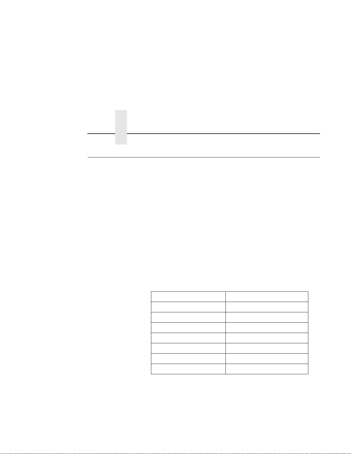
Interface Type Maximum Cable Length
Dataproducts Parallel 12 meters (40 feet)
IEEE 1284 Parallel 10 meters (32 feet)
Serial RS-232 15 meters (50 feet)
Serial RS-422 1220 meters (4000 feet)
Dataproducts Long Line 150 meters (492 feet)
Ethernet 10Base-T 100 meters (328 feet)
Ethernet 10Base2 185 meters (607 feet)
Page 17
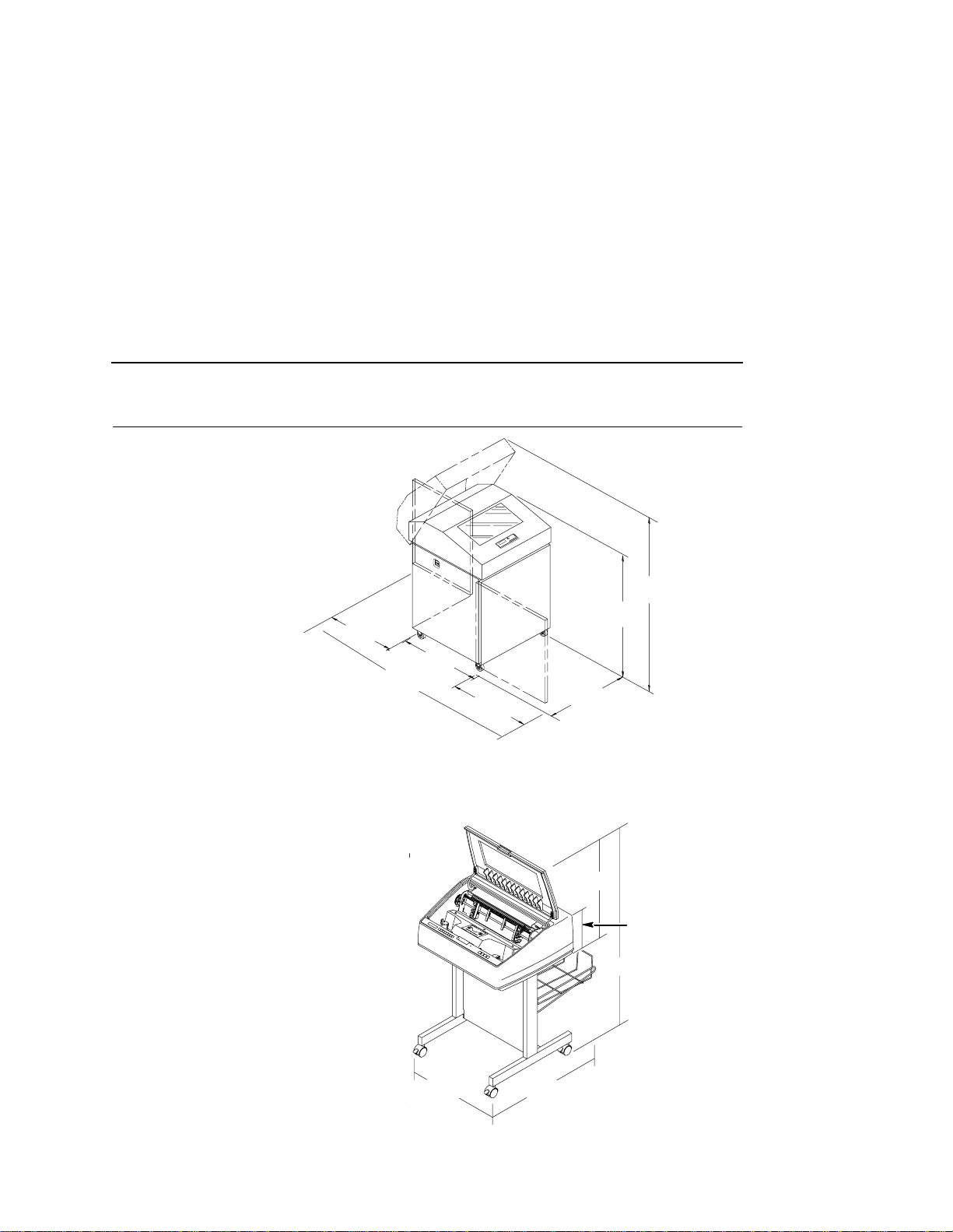
Printer Dimensions
57.5 in.
(146.1 cm)
41.0 in.
27.0 in.
(68.6 cm)
(210.8cm)
83.0 in.
29.0 in.
(73.7 cm)
27.0 in.
(68.6 cm)
(104 cm)
27.0 in.
(68.6 cm)
Figure 1. Printer Dimensions (Cabinet Model)
)
25 in.
(63.5 cm.)
10.5 in.
(26.67 cm.)
48.0 in.
(122 cm.)
24.6 in.
(62.48 cm.)
30 in.
(76.2 cm.)
Figure 2. Printer Dimensions (Pedestal Model)
17
Page 18
Chapter 2 Printer Component Locations
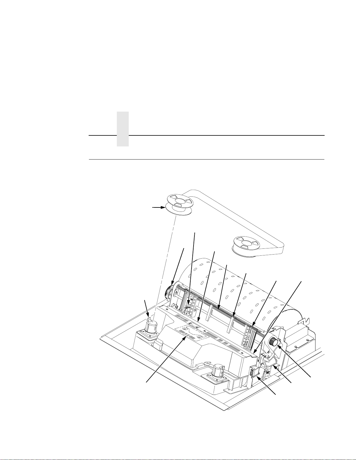
Printer Component Locations
Familiarize yourself with the names and locations of the printer
components, shown in Figure 3, before continuing with the rest of the
installation procedure.
2
4
13
3
1
5
6
7
8
12
9
10
11
18
Figure 3. Printer Component Locations
Page 19

Legend:
1) Hub Latch
2) Ribbon Spool
3) Horizontal Adjustment Knob
4) Tractor Lock
5) Paper Scale
6) Splined Shaft
7) Paper Support
8) Tractor
9) Hammer Bank Cover and Ribbon Mask
10) Vertical Position Knob
11) Forms Thickness Lever
12) Ribbon Guide
13) Ribbon Loading Path Diagram
Remove Packing Materials
CAUTION
To avoid shipping damage, reinstall the shipping restraints
whenever you move or ship the printer.
Save the cardboard packing, foam blocks, and bubble wrap along with
the other packing materials in case you need to move the printer. If it is
necessary to move the printer, reinstall the shipping restraints,
reversing the steps in this section.
19
Page 20
Chapter 2 Remove Packing Materials
1
3
2
20
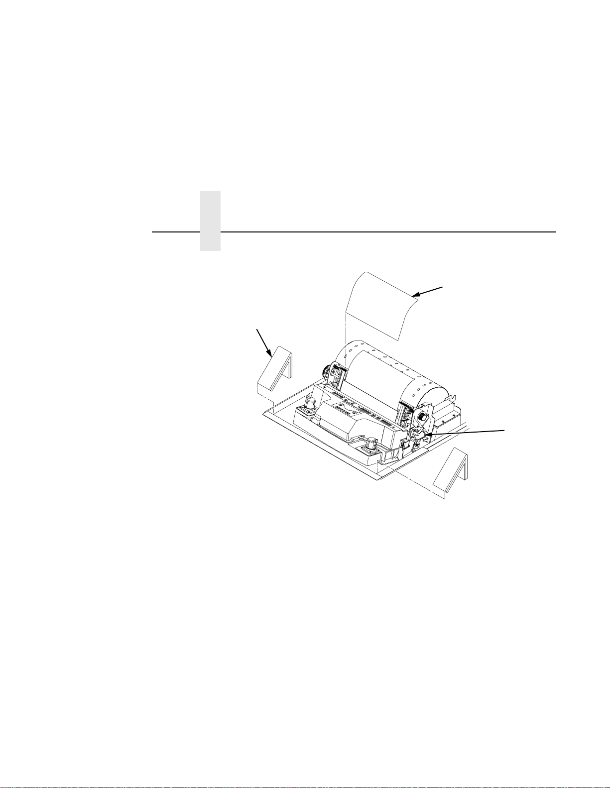
1. Raise the printer cover.
2. Remove the cardboard packing (1).
3. Open the tractor doors. Push the tractor locks down. Slide the
tractors outward as far as they will go. The forms thickness lever (2)
should be in the fully open (raised) position.
4. Remove the envelope (3) containing the sample configuration
printout. Store the envelope in the pouch attached to the left interior
side of the cabinet.
Page 21
6
5
4
7
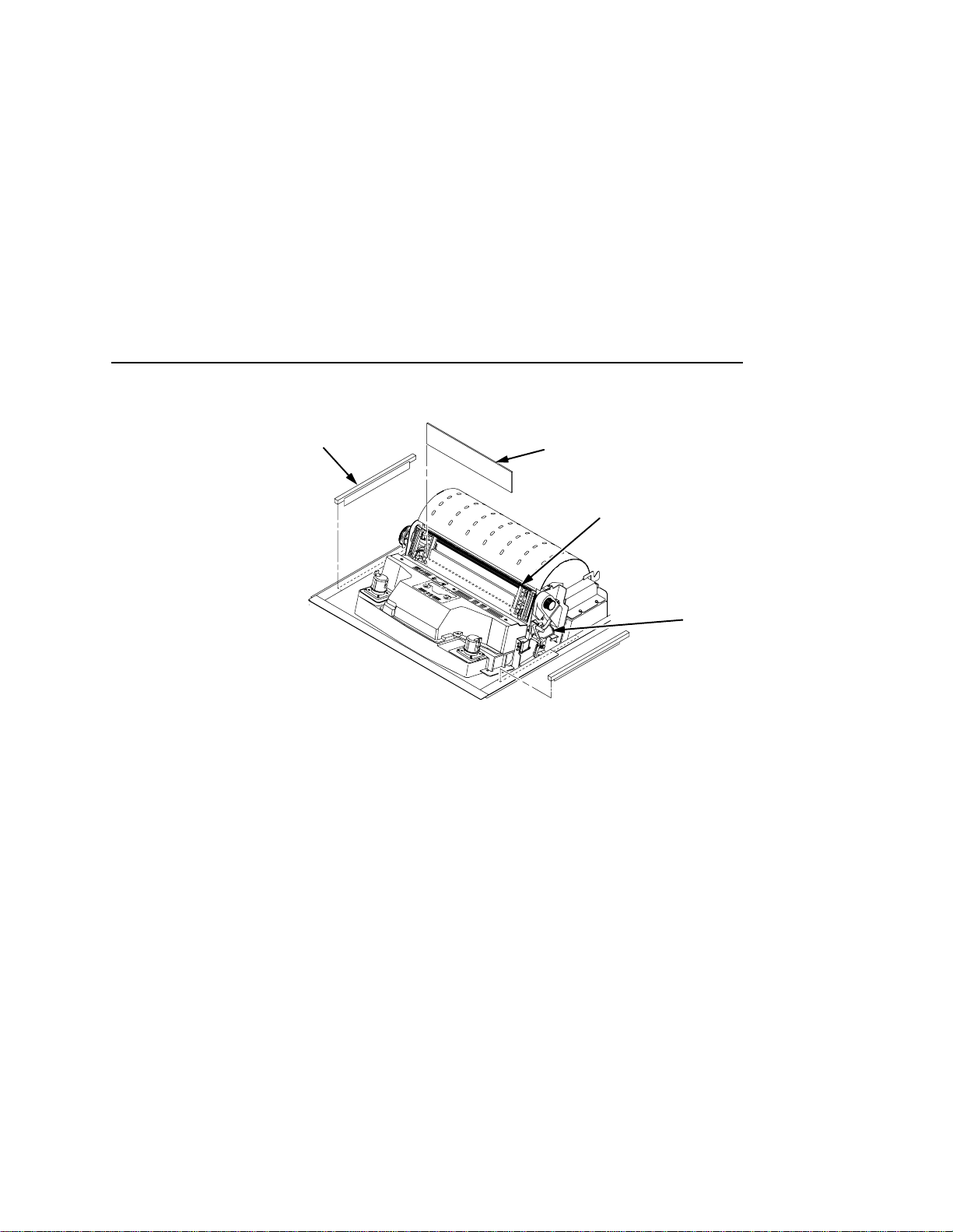
5. Slide the paper supports (4) outward as far as they will go. Lift the
hammer bank protective foam (5) and remove it from between the
ribbon mask and the platen.
6. Remove the foam strips (6) and the tape securing the foam strips.
7. Rotate the forms thickness lever (7) downward to position “A”.
21
Page 22
Chapter 2 Remove Packing Materials
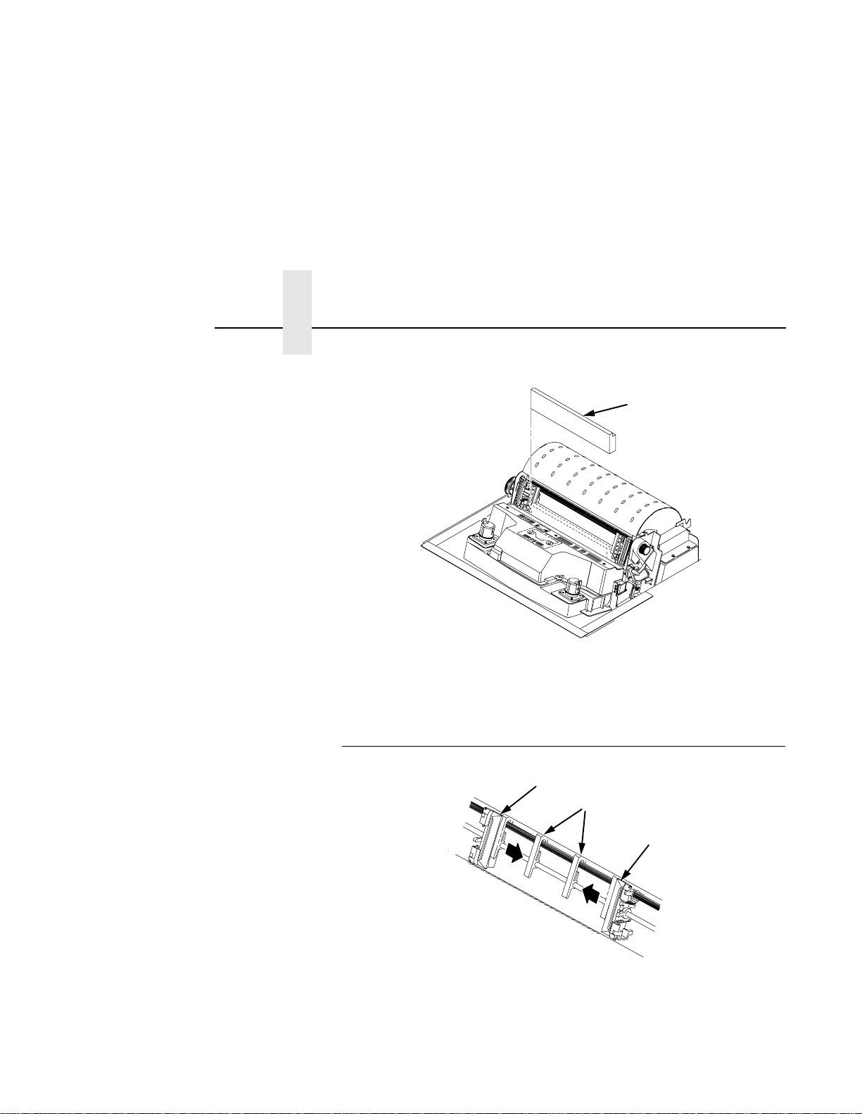
8. Rotate the platen protective foam (8) toward the front of the printer
and out from under the support shaft.
8
22
Adjust the Paper Supports
2
1
2
1. Slide the paper supports (1) inward until they are approximately
four inches from the tractor doors (2).
Page 23
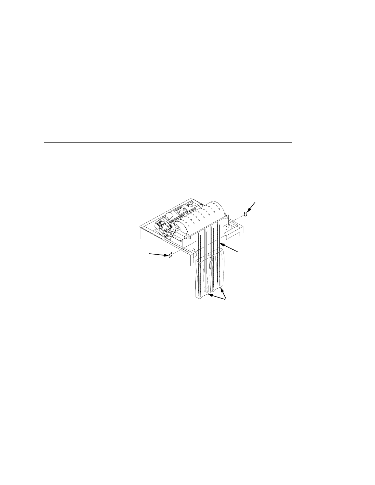
Release the Paper Chains (Cabinet Model)
Release the Paper Chain s (Cabinet Mode l)
1
1
1. Open the cabinet rear door.
2. Cut the tie wraps (1) and release the paper chains (2) from the
bags (3) at the top rear of the printer frame. Remove the tie wraps
and bags.
3. Make sure each chain hangs freely, with no kinks or knots.
2
3
23
Page 24
Chapter 2 Remove Packing Materials
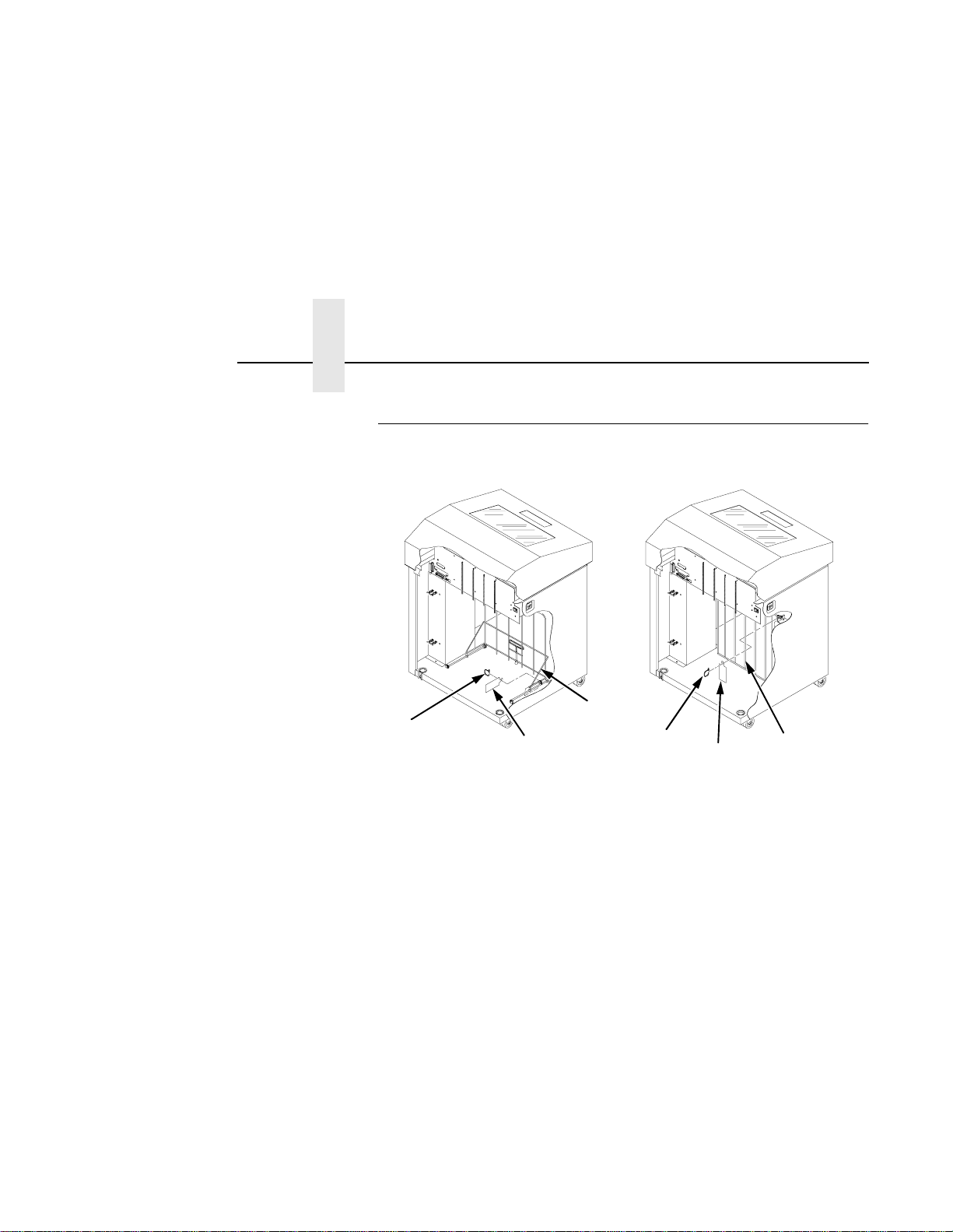
Remove T ags
Cabinet Model
1
2
3
1
2
3
24
Figure 4. Removing Tags
(Left: 1000/1500 lpm models; Right: 500 lpm models)
1. Remove the tie wrap (1) attached to the passive stacker paper
fence (3). It is marked with a large, red tag (2).
2. Close the cabinet rear door.
Page 25
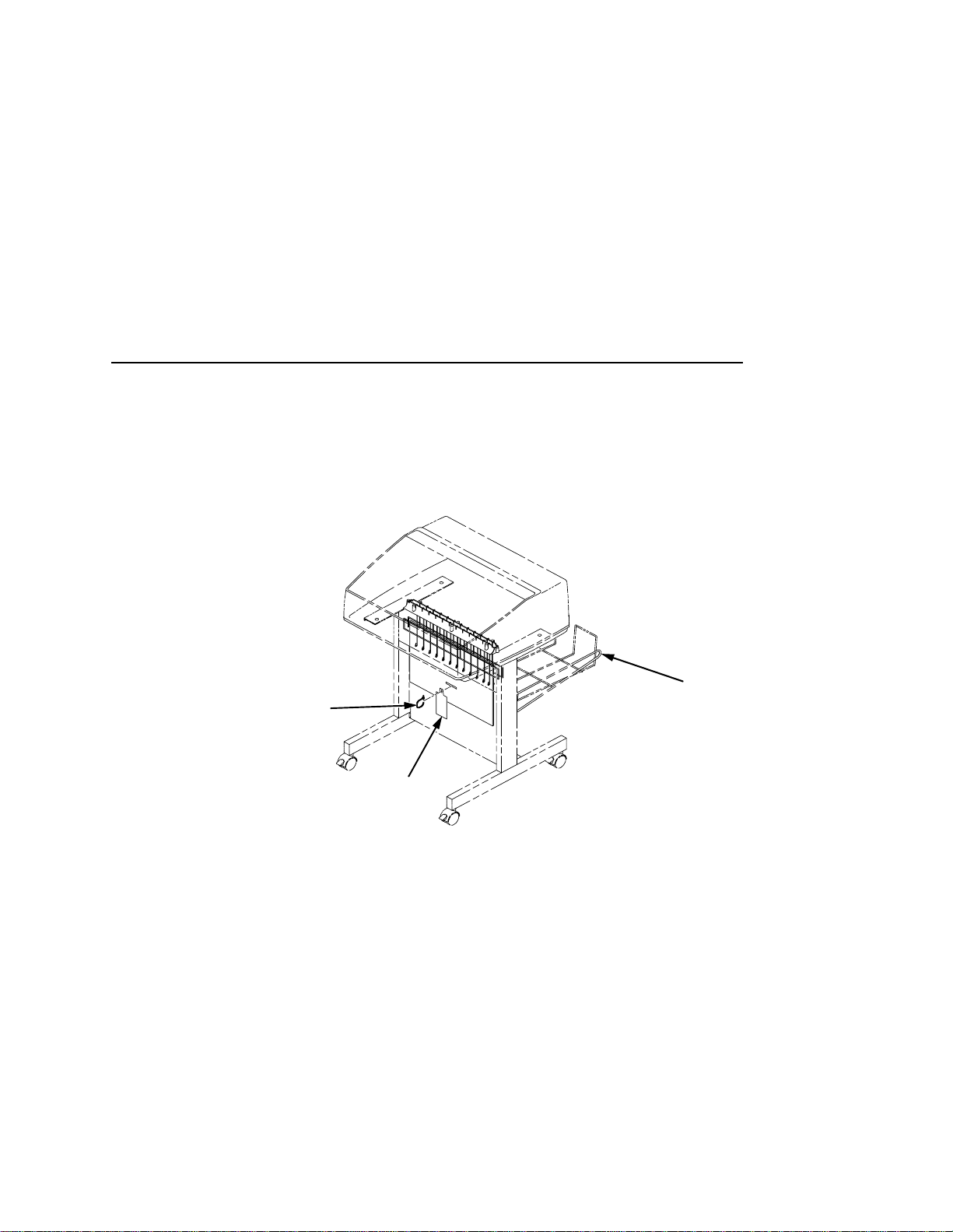
Pedestal Model
1
Remove Tags
3
2
Remove the tie wrap (1) attached to the output basket (3). It is marked
with a large, red tag (2).
25
Page 26
Chapter 2 Remove Packing Materials
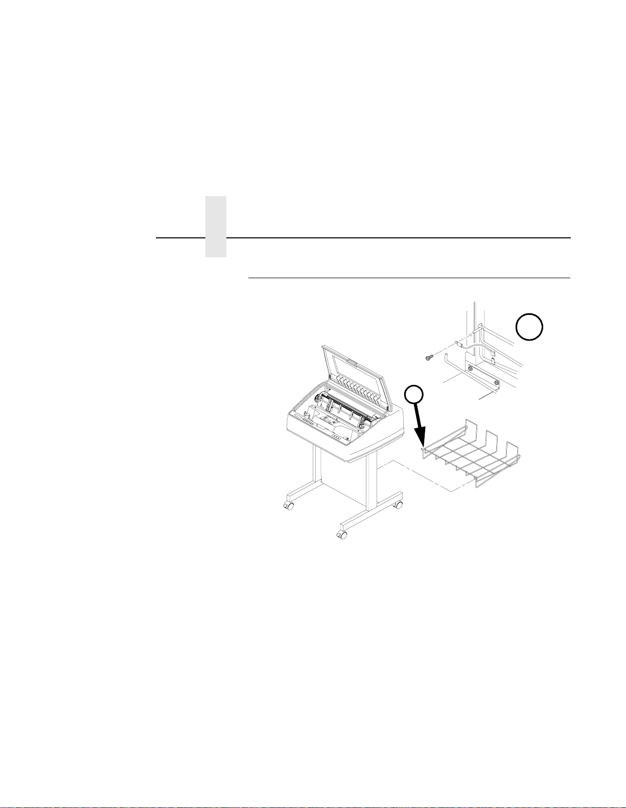
Attach the Ou tput Ba ske t (Pedest al M odel)
$
$
26
1. Place the output basket in the holes in the back of the printer.
2. Screw the ground wire attached to the output basket to the printer.
Page 27
Connect the Interface and Power Co rds
Before you connect the interface and power cables, verify the voltage
source at the printer site conforms to the requirements specified in
“Power Requirements” on page 15.
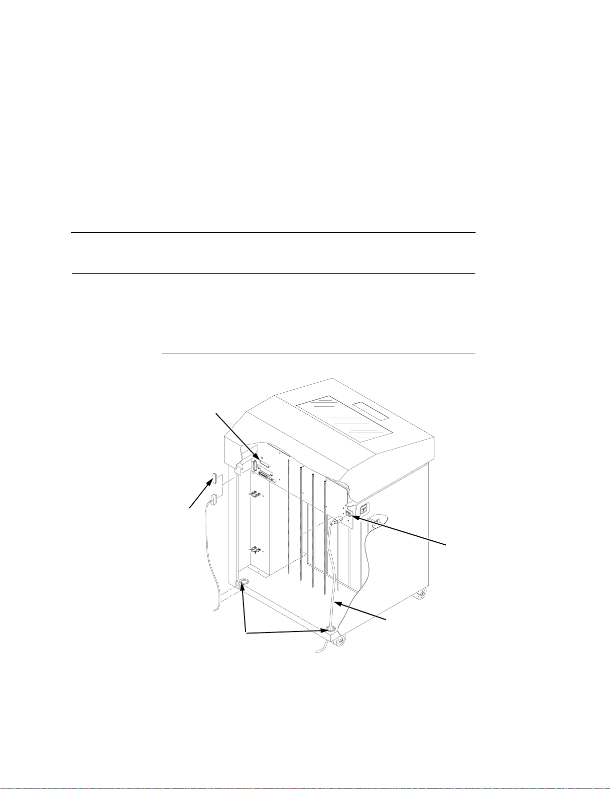
Cabinet Model
1
Cabinet Model
2
3
Legend:
1) Host Interface Connectors
2) I/O Cover
3) Cable-Routing Notches
4) AC Power Cable
5) AC Power Connection
Figure 5. Interface and Power Locations
5
4
27
Page 28
Chapter 2 Connect the Interface and Power Cords
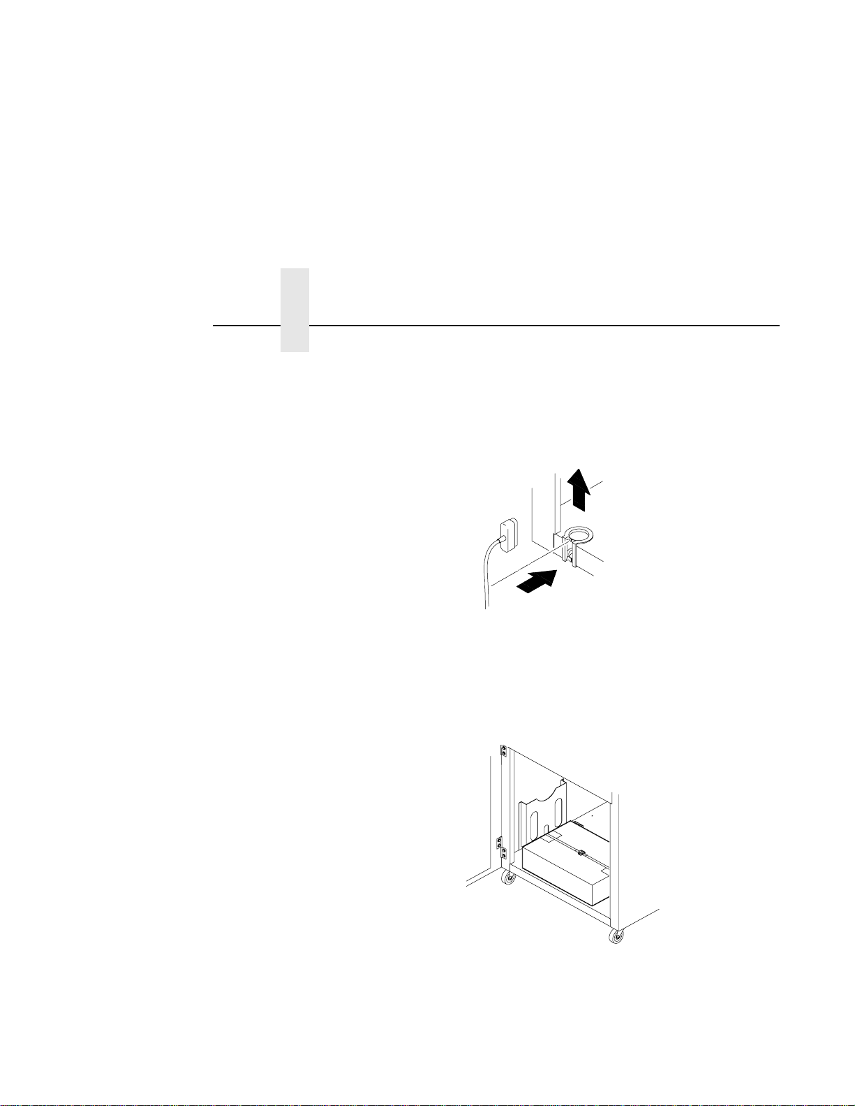
1. Make sure the printer power switch is set to O (Off).
2. Open the cabinet rear door, and remove the cover from the
selected I/O connector. (See “Interface Connections” on page 30.)
3. Locate the cable routing notch in the lower left corner of the back of
the cabinet (see Figure 5).
4. Hold the I/O cable below its connector and gently push the cable
through the opening in the grommet seated in the notch.
5. Pull the cable up through the notch until it reaches the I/O plate.
Attach the cable connector to the printer interface connector
previously selected in step 2 of this section. Secure the cable to the
printer using the upper and lower standoffs.
28
6. Open the cabinet front door and cut the strap that secures the box,
which contains the power cord, printer ribbon, control panel overlay
labels, and documentation.
7. Open the box and remove the power cord, overlays, and
documentation.
Page 29
Pedestal Model
8. Guide the power cord up through the hole in the lower right back
corner of the cabinet (see Figure 5). Thread the power cord inside
the bracket where the gas spring is attached.
9. Plug the power cord into the printer AC power connector, then into
the AC power outlet.
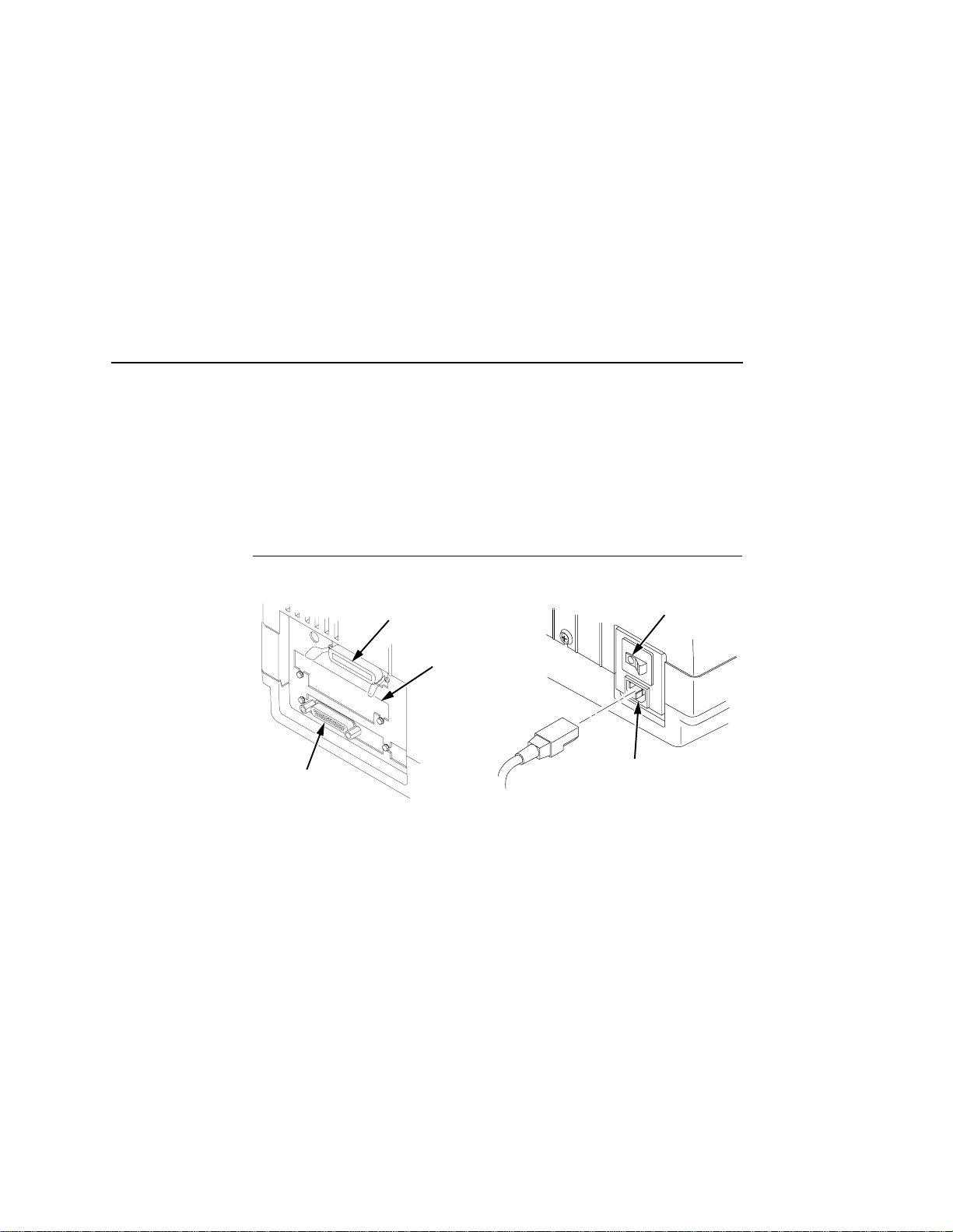
Pedestal Model
1
2
3
Legend:
1) Parallel Connector
2) Auxiliary I/O
3) Serial Connector
4) Power Switch
5) AC Power Connector
4
5
1. Make sure the printer power switch is set to O (OFF).
2. Remove the cover from the I/O connector you have selected. (See
below.)
3. Attach the cable connector to the printer interface connector.
Plug the power cord into the printer AC power connector, then into the
AC power outlet.
29
Page 30
Chapter 2 Connect the Interface and Power Cords
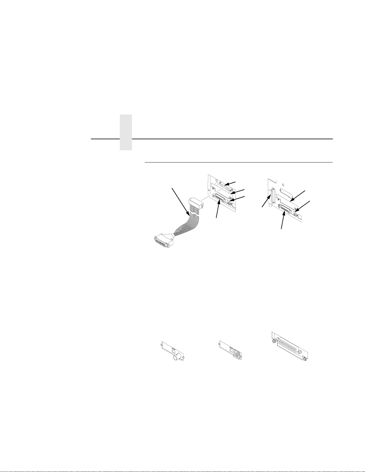
Interface Connections
5
4
Legend:
1) Parallel (not present on Network-based models)
2) Auxiliary I/O
3) Diagnostic
4) Serial RS-232/RS-422
5) Dataproducts Standard Adapter
1
2
3
1
Figure 6. Standard Interfaces
(Left: Pedestal Model; Right: Cabinet Model)
2
3
4
30
321
Legend:
1) Network 10Base2
2) Network 10Base-T
3) Dataproducts Long Line
Figure 7. Optional Interfaces for the Auxiliary I/O
1. Remove the cover from the I/O connector you have selected.
2. Attach the I/O cable connector to the printer interface connector.
Page 31

Install Basic Components
The following procedures describe how to attach the printed overlays to
the control panel and install the printer ribbon and paper.
Attach the Control Panel Overlays
1. Choose the overlay labels in the appropriate language.
2. Cabinet Models: Open the printer cover, peel off the protective
backing, and press the overlay into place.
3. Pedestal Models: Open the printer cover and insert overlay labels
by sliding them behind the control panel assembly in the
appropriate place.
Attach the Control Panel Overlays
Figure 8. Attaching Control Panel Overlays
(Left: Pedestal Models; Right: Cabinet Models)
31
Page 32

Chapter 2 Install Basic Components
Load the Ribbon
1. Refer to the ribbon path diagram molded onto the shuttle cover (see
“Printer Component Locations” on page 18).
2. Open the printer cover.
2
3. Raise the forms thickness lever (1) as far as it will go.
1
32
4. Open the tractor doors (2).
3
5. Squeeze the right hub latch (3) and place the full spool on the right
hub. Be sure the ribbon feeds off the outside of the spool. Press the
spool down until the hub latch snaps into place.
Page 33

Load the Ribbon
4
6. Thread the ribbon around the ribbon guide (4) and along the ribbon
path. Be sure to thread the ribbon between the hammer bank cover
and the ribbon mask.
7. Place the empty spool on the left hub. Press the spool down until
the hub latch snaps into place. Turn the empty spool by hand to
make sure the ribbon tracks correctly in the ribbon path and ribbon
guides.
33
Page 34

Chapter 2 Install Basic Components
Load the Paper
When you start this procedure, verify that the printer cover is open, the
forms thickness lever is raised, and the tractor doors are open. (See
“Printer Component Locations” on page 18).
Legend:
1) Edge Of Paper
2) Box
1. For cabinet models, align the paper supply with the label on the
floor. Make sure that the paper pulls freely from the box.
1
2
34
3
3
2. Feed the paper up through the paper slot (3). Hold the paper in
place with one hand (to prevent it from slipping down through the
paper slot) while pulling it through from above with your other hand.
Page 35

Load the Paper
5
4
6
3. Pul l the pape r (4) above and behind the ribbon mask, which is a
silver metal strip with a clear plastic edge protector. Load the paper
on the left tractor sprockets and close the tractor door (5).
CAUTION
To avoid damage to the printer caused by printing on the platen,
always position the left tractor unit directly to the left of the “1”
mark on the paper scale.
4. If adjustment is necessary, unlock (6) the left tractor. Slide the
tractor until it is directly to the left of the number “1” on the paper
scale (10) and lock it. You can also use the paper scale to count
columns.
7
5. Unlock the right tractor (7). Load the paper onto the right tractor
sprockets and close the tractor door.
35
Page 36

Chapter 2 Install Basic Components
9
6. Make sure the leading edge of the first sheet of paper is parallel to
the tractor splined shaft (8). If the paper is misaligned, reload it onto
the tractor sprockets until its edge is parallel to the splined shaft.
7. Slide the right tractor to remove paper slack or to adjust for various
paper widths. Lock the tractor.
8. After both tractors are secured, you may use the horizontal
adjustment knob (9) to make fine horizontal paper adjustments.
8
10
36
Page 37

Load the Paper
A
B
C
9. Lower the forms thickness lever. Set it to match the paper
thickness.
(The A-B-C scale corresponds approximately to 1-, 3-, and 6-part
paper thickness.)
NOTE: Do not set the forms thickness lever too tightly; excessive
friction can cause paper jams, ribbon jams with potential for
ribbon damage, smeared ink, or wavy print.
37
Page 38

Chapter 2 Set the Top-of-Form
Set the Top-of-Form
When paper is loaded into the printer, it must be told where you want
the top of your form to be. This procedure must be performed the first
time paper is introduced into the printer, as well as every time new
paper is loaded.
Procedure
1. Be sure the forms thickness lever is lowered. If the printer is off, set
the power switch to I (On).
2. Press ON LINE to place the printer in offline mode. The LCD will
then display “OFFLINE / CONFIG. CONTROL.”
3. Press FF several times to ensure the paper feeds properly beyond
the tractors and over the lower paper path. Ensure the paper folds
properly in the stacking area.
38
2
1
4. Raise the forms thickness lever (1) as far as it will go. This allows
you to turn the vertical position knob (2) freely in order to align the
top-of-form.
Page 39

Procedure
3
4
5. Locate the TOF indicator (3). It is the small tab located on both the
right and left tractor door.
6. Turn the vertical position knob (5) to align the top of the first print
line with the TOF indicator. For best print quality, it is recommended
the top-of-form be set at least 1/2 inch below the perforation (4).
5
39
Page 40

Chapter 2 Set the Top-of-Form
A
B
C
7. Lower the forms thickness lever. Set it to match the paper
thickness. (The A-B-C scale corresponds approximately to 1-, 3-,
and 6-part paper thickness.)
NOTE: Do not set the forms thickness lever too tightly; excessive
friction can cause paper jams, ribbon jams with potential for
ribbon damage, smeared ink, or wavy print.
40
8. Press SET TOF. The top-of-form position you have set moves
down to the print position.
9. Press CLEAR to remove any fault messages (such as “LOA D
PAPER”) from the message display.
10. Press ON LINE to place the printer in online mode.
Page 41

3 Operating the Printer
Powering On the Printer
When you power on the printer, it executes a self-test. The default
power-up state is online. When the self-test completes and the software
has initialized successfully, the status indicator light turns on, indicating
the printer is online. The default value of the type of emulation you have
installed appears in the display.
If there is a fault during the self-test, the status indicator flashes and a
specific fault message appears on the display (such as “LOAD
PAPER”). The alarm also sounds if it is configured to do so. See
“Troubleshooting” on page 195 for information on fault messages and
solutions.
Operating Modes
Online. In online mode, the printer can receive and print data sent from
the host. Pressing the ON LINE key toggles the printer from offline to
online mode. The status indicator is lit in online mode.
Offline. In offline mode, you may perform operator functions, such as
loading paper and setting top-of-form. You may also move within the
printer configuration menus. Pressing the ON LINE key toggles the
printer from online to offline mode. The status indicator is off in offline
mode.
Fault. In fault mode, a fault condition exists which must be cleared
before printing can continue. The status indicator flashes, the alarm
beeps (if configured to sound), and a descriptive fault message
displays.
41
Page 42

Chapter 3 The Control Panel
The current operating mode may be selected via control panel keys, or
may result from routine operations such as powering on the printer.
The Control Panel
Figure 9 and Figure 10 show the keys, displays and indicators as they
appear on the control panel. The following section provides descriptions
of each of the control panel keys and their functions.
Key combinations are indicated with the plus (+) sign. For example,
“Press
time.
= + >” means to press the = key and the > key at the same
3
4
5
6
1
;<
1
Figure 9. Control Panel, Cabinet Model
2
=>
34 6 8 10
579
2
78910
42
Figure 10. Control Panel, Pedestal Model
Page 43

Control Panel Keys
Legend:
1) Message Display
2) Status Indicator
3) CLEAR
4) SHIFT
5) SET TOF / L.P.I. ADJ.
6) ENTER / PAGE L. ADJ.
7) ON LINE
8) FF
9) LF
10) VIEW
Control Panel Keys
ON LINE
Toggles the printer between online and offline modes. If a fault
condition exists, pressing this key will clear the fault message and
return the printer from fault mode to offline mode.
NOTE: If the fault condition is not corrected
before
pressing this key,
the fault message will reappear when attempting to place the
printer online.
FF (Form Feed)
Causes the paper to advance to the top-of-form on the next page.
In online or offline mode, press and release to advance the paper to
top-of-form on the next page. If there is data in the printer buffers, the
data will print and then the paper will move to the next top-of-form.
In the fault state, FF does not advance the paper to the next top-ofform; instead, it will slew the paper 11 inches.
LF (Line Feed)
Advances the paper one line at a time. Unprinted data in the print buffer
will print before the paper moves.
With the printer offline, press and release to advance the paper one line
at a time. If there is data in the printer buffer, the data will print before
the line feed occurs. Press and hold to repeat forward paper movement.
LF does not operate in the fault or online states.
43
Page 44

Chapter 3 The Control Panel
VIEW
In offline or online mode, allows you to view and adjust the placement of
data on the page, or to remove peel-off labels.
With the printer online or offline, press and release to move paper
forward for inspection. The last data printed advances to the tractor
area. Press VIEW a second time to move the paper back to its previous
print position.
If the printer is online and printing, press VIEW to stop printing. The
paper advances. Press
forms alignment. Press VIEW. The paper moves back and printing
resumes.
Pressing ON LINE also moves the paper back to its original print
position and returns the printer to online.
CLEAR
Clears a fault message and returns the printer from fault mode to offline
mode.
= or > to move 1/72” vertically for fine vertical
44
After correcting the fault, press and release. The fault message is
cleared, and the printer returns to offline mode.
Other functions:
• Moves to the top of the configuration menu when the printer is in
the configuration menus.
• Cancels data in the buffer. Place the printer offline. From the host
system, stop the print job. Press CLEAR+ENTER. Reset the top-ofform (page 38).
• Press SHIFT+CLEAR to reset the PCL-II emulation.
Page 45

Control Panel Keys
SHIFT
The printer must be offline to perform the following functions:
• Press SHIFT+CLEAR to reset the PCL-II emulation.
• Press SHIFT+L.P.I. Adj to access the line spacing menu. Press
PREV or NEXT to scroll through the options.
• Press SHIFT+Page L. Adj to access the form length menu in lines
or inches. The page length is selected by lines/page or inches/
page, depending on which option is chosen in the PCL-II submenu.
• Press SHIFT+= to micro step the paper upward in 1/72 inch
increments.
• Press SHIFT+> to micro step the paper downward in 1/72 inch
increments.
SET TOF
Sets the top-of-form on the printer. This key is active only when the
printer is offline and will not operate if the printer is in a fault condition.
The paper moves down to the print position and aligns to the top-ofform. See page 38 for the complete top-of-form setting procedure.
NOTE: If there is any data in the buffer, the paper will move to the last
print position.
ENTER
When navigating the configuration menus, ENTER selects the currently
displayed option value as the active value. An asterisk (*) appears next
to the active value on the display. ENTER is also used for starting and
stopping printer tests and generating a configuration printout.
NOTE: The ENTER key must be unlocked in order to function. See
UP + DOWN, below.
45
Page 46

Chapter 3 The Control Panel
UP or DOWN ( = or > )
Moves up and down between levels in the configuration menus and
makes vertical forms adjustment. After pressing VIEW, press
adjust the paper up or down in 1/72 inch increments for fine vertical
forms alignment. After pressing ON LINE, press
levels in the configuration menus.
= or > to
= or > to move through
UP + DOWN (
Locks and unlocks the ENTER key.
PREV or NEXT (
Moves between the options on the current level of configuration menu.
In the configuration menu press
forward through the menu selections on the same level.
PREV + NEXT (
When both keys are pressed simultaneously, the printer performs a soft
reset of the LP+ emulation and the printer buffers are cleared.
= + > )
; or < )
; to scroll backward or press < to scroll
; + < )
46
Page 47

Operational Procedures
This section outlines certain basic procedures which need to be
performed when necessary in order to keep your printer operating.
Reloading Paper
Follow this procedure when “LOAD PAPER” displays. (This message
occurs when the last sheet of paper passes through the paper slot.)
This procedure reloads paper without removing the last sheet of the old
paper supply. This action retains the current top of form setting.
1. Raise the printer cover. Raise the forms thickness lever as far as it
will go. (See Figure 3 on page 18 for the location of the lever.)
2. Press CLEAR to turn off the alarm. Do not open the tractor doors or
remove the existing paper.
3. For cabinet models, open the front door. Align the paper supply
with the label on the floor. Ensure the paper pulls freely from the
box.
Reloading Paper
2
1
Legend:
1) Paper Slot (Cabinet Model)
2) Paper Slot (Pedestal Model; 8” below printer base)
Figure 11. Paper Slot Location
47
Page 48

Chapter 3 Operational Procedures
4. Locate the paper slot and feed the paper up through it (see Figure
11). It may be easier to feed one corner of the new paper up
through the slot first. When this corner can be grasped from the top,
rotate the paper back to the normal position.
NOTE: If you are using thick, multi-part forms and are unable to load
the new paper over the existing paper, go to step 14.
5. Hold the paper to prevent it from slipping down and through the
paper slot.
3
5
4
6
6. Pull the new paper (3) above and behind the ribbon mask, but in
front of the existing paper (4). The ribbon mask location is shown
on the ribbon path diagram (5). If necessary, gently press the
existing paper back.
7. Align the top edge of the new paper with the top perforation of the
existing paper (6).
8. Load the new paper over the existing paper. Open and load the
tractors one at a time to prevent the paper from slipping.
48
NOTE: Make sure that the top edge of the new paper lines up with the
top horizontal perforation of the last page.
Page 49

Reloading Paper
A
B
C
9. Lower the forms thickness lever. Set it to match the paper
thickness.
(The A-B-C scale corresponds approximately to 1-, 3-, and 6-part
paper thickness.)
NOTE: Do not set the forms thickness lever too tightly; excessive
friction can cause paper jams, ribbon jams with potential for
ribbon damage, smeared ink, or wavy print.
10. Press CLEAR to remove the “LOAD PAPER” fault message from
the display.
11. Press FF several times to make sure the paper feeds properly
beyond the tractors and over the lower paper guide. Feed sufficient
paper to ensure the paper stacks correctly.
12. Close the printer cover. Close the cabinet front door.
13. Press ON LINE
printing.
to place the printer in online mode and resume
49
Page 50

Chapter 3 Operational Procedures
Perform steps 14 through 30 only if you are unable to load the new
paper over the existing paper in step 4.
14. Open both tractor doors.
15. Remove the paper from the tractors. Allow the paper to fall into the
paper supply area.
7
7
50
16. Feed the paper up through the paper slot (7). Hold the paper to
prevent it from slipping down through the paper slot.
Page 51

Reloading Paper
9
8
17. Pull the paper (8) above and behind the ribbon mask. (The ribbon
mask location is shown on the ribbon path diagram.)
18. Load the paper on the left tractor and close the tractor door (9).
CAUTION
To avoid damage to the printer caused by printing on the platen,
always position the left tractor unit directly to the left of the “1”
mark on the paper scale.
19. Normally, you should not need to adjust the position of the left
tractor. If adjustment is necessary, unlock the left tractor. Slide the
tractor until it is directly to the left of the number “1” on the paper
scale and lock it. (You can also use the paper scale to count
columns.)
51
Page 52

Chapter 3 Operational Procedures
20. Move the paper supports (10 ) as necessary to support the paper
between the tractors.
10
11
52
12
21. Unlock the right tractor (11). Load the paper onto the sprockets and
close the tractor door (12). If necessary, slide the right tractor to
remove paper slack or to adjust for various paper widths. Then, lock
the tractor.
13
22. After both tractors are secured, you may use the horizontal
adjustment knob (13) to make fine horizontal paper adjustments.
Page 53

Reloading Paper
14
14
23. On pedestal models:
Using the vertical position knob to move the paper up, guide the
paper over the lower paper guide (14) and through the slot in the
top cover. Close the platen and the printer cover.
24. Press FF several times to make sure the paper feeds properly
beyond the tractors and over the lower paper guide (14). Feed
sufficient paper to ensure the paper stacks correctly.
25. On cabinet models: Open the cabinet rear door. Make sure the
paper is aligned with the label in the output area (inside the
cabinet). Close the front and rear doors.
53
Page 54

Chapter 3 Operational Procedures
15
16
17
26. Locate the TOF indicator (15). It is the small tab located on both the
right and left tractor door.
27. Turn the vertical position knob (16) to align the top of the first print
line with the TOF indicator. For best print quality, it is recommended
the top-of-form be set at least 1/2 inch below the perforation (17).
A
B
C
54
28. Lower the forms thickness lever. Set it to match the paper
thickness. (The A-B-C scale corresponds approximately to 1-, 3-,
and 6-part paper thickness. Adjust until you have the desired print
quality.)
29. Press CLEAR to clear any fault messages (such as “LOAD
PAPER”) from the Liquid Crystal Display.
Page 55

Unloading Paper
30. Press SET TOF. The top-of-form you have set moves down to the
print position. If there are data in the buffer, the paper moves
forward to the last print position on the next page.
31. Press ONLINE and close the printer cover.
Unloading Paper
1. Press ON LINE to place the printer in offline mode, and open the
printer cover.
2. For cabinet models, open the cabinet rear door.
3. Tear off the paper at the perforation.
4. Allow the paper to fall to the back of the printer and into the paper
stacking area.
5. For pedestal models, remove the stacked paper from the paper
tray.
6. For cabinet models, remove the stacked paper from the cabinet
floor.
55
Page 56

Chapter 3 Operational Procedures
2
1
CAUTION
56
7. To completely remove the paper from the printer:
a. Raise the forms thickness lever (1) as far as it will go, and open
both tractor doors (2).
Be careful when pulling any paper backward through the paper
path, especially when using a label stock. If you are not careful,
labels can detach and adhere to the printer within the paper path,
where only an authorized service representative can remove them.
b. Remove the paper from the tractors. For cabinet models, open
the cabinet front door. Gently pull the paper down through the
paper slot. Allow the paper to fall into the paper supply area.
c. Remove the paper from the paper supply area.
Page 57

Replacing the Ribbon
Replacing the Ribbon
1. Press ON LINE to place the printer in offline mode.
2. Open the printer cover.
2
3. Remove the old ribbon:
a. Raise the forms thickness lever (1) as far as it will go.
b. Press in on the hub latches (2) and lift the ribbon spools off the
hubs. Lift the ribbon out of the ribbon path.
4. Discard the old ribbon.
5. If necessary, clean the interior of the printer. (See “Cleaning
Requirements” on page 195.)
1
57
Page 58

Chapter 3 Operational Procedures
6. Install the new ribbon:
a. With the ribbon to the outside, place the full spool on the right
hub (3). Press down on the spool until the hub latch snaps in
place.
CAUTION
58
3
b. Thread the ribbon around the ribbon guide (4) and along the
ribbon path. (Refer to the ribbon path diagram on the shuttle
cover.) Be sure to thread the ribbon between the hammer bank
cover and the ribbon mask.
The ribbon must not be twisted. A twisted ribbon can lower print
quality, shorten ribbon life, or cause paper jams.
c. Place the empty spool on the left hub. Press down on the spool
until the hub latch snaps into place.
d. Hand turn the empty spool to make sure the ribbon tracks
correctly in the path and ribbon guides.
4
Page 59

Replacing the Ribbon
A
B
C
7. Lower the forms thickness lever. Set it to match the paper
thickness. (The A-B-C scale corresponds approximately to 1-, 3-,
and 6-part paper thickness.)
NOTE: Do not set the forms thickness lever too tightly; excessive
friction can cause paper jams, ribbon jams with potential for
ribbon damage, smeared ink, or wavy print.
8. Close the printer cover.
9. Press ON LINE to return the printer to online mode.
59
Page 60

Chapter 3 Operational Procedures
Canceling a Print Job
The procedure to cancel a print job depends on the printer emulation
and your application software. Contact your System Administrator for
additional information.
1. If the printer is online, press ON LINE to place the printer in offline
mode.
2. From the host system, stop the print job.
NOTE: If the print job is not stopped from the host system before
pressing CLEAR + ENTER, the print job continues with data
missing when the printer returns to online mode. Exercise
caution to prevent unwanted data loss occurrences, as this
function deletes unprinted data in the printer. This function is
active only in offline mode; the purpose of this function is to
eliminate the necessity of printing unwanted data when print
jobs are canceled.
3. Press CLEAR + ENTER.
4. Set the top-of-form (see “Set the Top-of-Form” on page 38).
60
Page 61

4 The Configuration
Menus
Configuration Over view
In order to print data, the printer must respond correctly to signals and
commands received from the host computer. Configuration is the
process of matching the printer’s operating characteristics to those of
the host computer and to specific tasks, such as printing labels, or
printing on different sizes of paper. The characteristics which define the
printer’s response to signals and commands received from the host
computer are called configuration parameters.
You can configure the printer using the configuration menus and the
control panel, or by sending control codes in the data stream from a
host computer attached to the printer. This chapter provides an
introduction to configuring the printer, as well as all the configuration
menus available (depending on which emulation you have installed in
the printer).
IMPORT ANT
Configuration directly affects printer operation. Do not change the
configuration of your printer until you are thoroughly familiar with
the procedures in this chapter.
61
Page 62

Chapter 4 Configuration Overview
Changing and Saving Parameter Settings
You may change a printer parameter setting, such as line spacing or
forms length, either by pressing keys on the control panel to configure
the printer’s resident set of configuration menus, or by sending
emulation control codes from a host attached to the printer (the host
data stream). An example procedure for using the control panel to
change parameter settings begins on page 64.
When control codes are sent from a host attached to the printer, they
override control panel settings. For example, if you set the line spacing
to 6 lpi with the control panel, and application software later changes
this to 8 lpi with a control code, the control code overrides the control
panel setting.
The parameter settings that you have changed using the menus and
control codes can be permanently stored in the printer’s memory if you
save them to printer memory using the “Save Config.” menu option. If
you do not save your changes, they will be lost when the printer is
powered off.
62
There are no host control codes that allow you to save a parameter as a
custom configuration.
Default and Custom Configurations
A configuration consists of a group of parameter settings, such as line
spacing, forms length, etc. Your printer provides a fixed default
configuration and also allows you to define several custom
configurations for use with particular print jobs.
The factory default configuration can be loaded, but it cannot be
altered.
Eight configurations can be modified for unique print job requirements.
The “Save Config.” option allows you to save eight groups of parameter
settings in memory as custom configurations numbered from 1 through
8. An explanation on how to save a set of parameter values as a
custom configuration using the “Save Config.” menu option begins on
page 66.
Page 63

Navigating the Menus
ON LINE
OR
OR
ENTER
+
Navigating the Menus
To manipulate configurations it is important to understand how to
navigate through the menus. Review the following instructions before
you begin making changes to the printer.
You must be offline to move within the menus.
Press to toggle between online and offline
modes.
Press to move up or down through the menu
levels.
Press to scroll through the available choices
on a chosen level.
Press to confirm selection.
Press to lock and unlock the ENTER key. The
ENTER key is locked by default, to prevent
you from accidentally changing the printer
configuration.
When the printer is online, the LCD displays ONLINE and the type of
emulation on the second line.
To experiment with navigating the menus, follow the example on the
next page as a tutorial.
63
Page 64

Chapter 4 Configuration Overview
Changing Param e ters Ex ample
OFFLINE
* = Factory Default
CONFIG.
CONTROL
. . .
PRINTER
CONTROL
Unidirectional
Disable*
Enable
PMD Fault
Enable*
Disable
Slow Paper
Slew
Disable*
Enable
Power Saver
Time
15 min.*
(15-60 min.)
A configuration consists of several parameters. The default factory
configuration has a starting set of parameters. In the configuration
menu above, and in all the configuration menus in this chapter, the
factory default values are indicated by an asterisk (*).
Your print jobs may require parameter values which vary from the
default settings. This section provides an example procedure for
changing individual parameter values.
64
The following procedure shows how to change and save the settings for
the Unidirectional and Slow Paper Slew options. Use these basic
guidelines to navigate the configuration menus and change other
parameters.
Page 65

Changing Parameters Example
ON LINE
+
UNTIL
OR
ENTER
UNTIL
OR
Step Press LCD Notes
1. Make sure the printer is on. Raise the printer cover.
2. OFFLINE
CONFIG. CONTROL
3. ENTER SWITCH
UNLOCKED
OFFLINE
CONFIG. CONTROL
4. OFFLINE
PRINTER CONTROL
5. PRINTER CONTROL
Unidirectional
6. Unidirectional
Disable*
7. Unidirectional
Enable
8. Unidirectional
Enable*
Allows you to make
configuration changes.
Cycle through the
choices.
The * indicates this choice
is active.
9. PRINTER CONTROL
Unidirectional
10. PRINTER CONTROL
Slow Paper Slew
11. Slow Paper Slew
Disable*
12. Slow Paper Slew
Enable
Press until the desired
parameter displays.
65
Page 66

Chapter 4 Configuration Overview
Step Press LCD Notes
13. Slow Paper Slew
14. ENTER SWITCH
15. ONLINE
16. Close the printer cover. The printer is ready for operation.
ENTER
+
ON LINE
Enable*
LOCKED
LinePrinter+
The parameters you have changed remain active as long as the printer
is on. When you turn off the printer, the parameters are erased from
memory unless you save them in a configuration. If you do not save the
configuration, the printer reverts to the default values next time the
printer is powered on.
The next section, “Saving Your New Configuration”, will explain how to
save configurations.
Saving Your New Configuration
Once you have changed all of the necessary parameters, it is
recommended you save them as a configuration that can be stored and
loaded for future use. If you do not save your configuration before you
power off the printer, all of your parameter changes are erased. The
Save Config. option allows you to save up to eight configurations to
meet different print job requirements. (Configurations 1 through 8 are
empty until you save values to them using the Save Config. option.)
The * indicates this choice
is active.
Locks the ENTER key.
Places the printer in
online mode.
66
Page 67

Saving Your New Configuration
ON LINE
+
UNTIL
OR
Once you have saved a custom configuration using this option, it is not
lost if you power off the printer. You can load a configuration for a
specific print job (see “Load Config.” on page 71). You can also modify
and resave it. You may want to print your configurations (see “Print
Config.” on page 72) and store them in a safe place, such as inside the
printer cabinet.
If the Protect Configs. parameter is enabled, and you try to resave an
existing configuration, the new configuration will not be saved until the
existing configuration has been deleted (see page 72).
NOTE: Once you change active emulations, any changes to the
previously selected emulation will be gone unless they have
been saved.
Step Press LCD Notes
1. Make sure the printer is on. Raise the printer cover.
2. OFFLINE
CONFIG. CONTROL
3. ENTER SWITCH
UNLOCKED
OFFLINE
CONFIG. CONTROL
4. CONFIG. CONTROL
Load Config.
5. CONFIG. CONTROL
Save Config.
6. Save Config.
1*
7. Save Config.
2
Allows you to make
configuration changes.
Cycle through the
choices.
67
Page 68

Chapter 4 Configuration Overview
Step Press LCD Notes
8. Save Config.
ENTER
2*
The * indicates this choice
is active.
NOTE: It is recommended you print the configuration. To print the configuration go to Step 9. To
skip this procedure and resume printer operation, go to Step 14.
9. CONFIG. CONTROL
Save Config.
10. CONFIG. CONTROL
UNTIL
Print Config.
11. Print Config.
Current
12. Print Config.
OR
13. OFFLINE
14. ENTER SWITCH
15. ONLINE
ENTER
+
ON LINE
2
CONFIG. CONTROL
LOCKED
Press until the desired
parameter displays.
The selected
configuration is printed.
Locks the ENTER key.
LinePrinter+
16. Close the printer cover. If you printed out the configuration, store it in a safe place. The printer is
ready for operation.
68
Page 69

OFFLINE
Main Menu
Main Menu
1
If installed
CONFIG.
CONTROL
page 71
Load Config.
Save Config.
Print Config.
Delete Config.
Power-up Config.
Protect Configs.
ETHERNET
PARAMS
page 122
IP Address
Gateway Address
Subnet Mask
MAC Address
1
ACTIVE
EMULATION
page 73
PCL-II
LP PLUS
IGP/PGL
IGP/VGL
Unidirectional
PMD Fault
Slow Paper Slew
Power Saver Time
1
1
PRINTER
CONTROL
page 123
EMULATION
page 74
PCL-II
LP PLUS
IGP/PGL
IGP/VGL
DIAGNOSTICS
Printer Tests
Test Width
Paper Out Dots
System Memory
Print Statistics
1
1
page 125
MAINT/MISC
page 112
Hex Dump Mode
Power-up State
Display Language
RIBBON
MINDER
page 128
New Ribbon
Ribbon Action
Ribbon Size
Ribbon Adjust
Fault Action
HOST
INTERFACE
page 113
Dataproducts
Serial
Ethernet
IEEE 1284
1
Figure 12. Configuration Main Menu
69
Page 70

Chapter 4 Configuration Overview
Brief descriptions follow for the first-level configuration menu options:
• CONFIG. CONTROL — These options allow you to save, print,
load, delete, name, and protect entire sets of configuration
parameters, as well as select the default power-up configuration.
• ACTIVE EMULATION — This menu allows you to select the active
emulation: PCL-II or LinePrinter+. The optional IGP/PGL or
IGP/VGL emulations can be selected if they are installed.
• EMULATION — This menu allows you to configure the options
which are available for the current operating (active) emulation. For
example, if LinePrinter+ is the active emulation, then the
LinePrinter+ emulation options can be configured using this menu.
• MAINT / MISC — These options provide miscellaneous functions,
such as printing a hex dump, selecting a display language, and
choosing whether the printer will power up in offline or online mode.
• HOST INTERFACE — These options allow you to select either the
®
Serial RS-232, Serial RS-422, Dataproducts
Ethernet
must match the interface cabling you installed while setting up your
printer, described in Chapter 2). This menu also allows you to
configure several par ame ter s for each int er fac e.
™
, or IEEE1284 parallel interface for the printer (which
Long Line,
• ETHERNET PARAMS — This option allows you to view and
change the IP Address, Gateway Address, and Subnet Mask. The
MAC Address may also be viewed.
• PRINTER CONTROL — These options allow you to select several
operating parameters for the printer, such as the speed at which
paper will advance when slewing.
• DIAGNOSTICS — These options include the diagnostic tests,
system memory, and statistics of the printer.
• RIBBONMINDER — The options in this submenu allow you to
™
enable the RibbonMinder
feature and set its parameters.
70
Page 71

CONFIG. CONTROL
The CONFIG. CONTROL menu allows you to control your printer’s
configurations according to the specifications necessary for your print
jobs.
Menu
CONFIG.
CONTROL
(from page 69)
Menu
* = Factory Default
Load Config.
Factory*
1-8
Save Config. Print Config.
1*
(1-8)
Current*
Factory
Power-up
All
1-8
Delete Config.
1*
(1-8)
Power-up
Config.
Factory*
1-8
Protect
Configs.
Disable*
Enable
Load Config.
The printer can store numerous configurations in memory. This
parameter allows you to select and load a specific configuration.
71
Page 72

Chapter 4 CONFIG. CONTROL
Save Config.
This option allows you to save up to eight unique configurations to meet
different print job requirements. This eliminates the need to change the
parameter settings for each new job. The configurations are stored in
memory, and will not be lost if you turn off the printer. If the Protect
Configs. parameter is enabled, the new configuration will not be saved
unless the existing configuration has been deleted first. The factory
default configuration cannot be changed. See “Saving Your New
Configuration” on page 66 for details.
Print Config.
This option is used to print a listing of various stored printer
configurations. It is recommended you store printouts of your
configurations in a safe place for quick referral.
Delete Config.
You can delete one or all of your eight customized configurations. The
factory default configuration cannot be deleted.
72
Power-Up Config.
You can specify which of the nine configurations (Factory or 1-8) will be
the power-up configuration.
Protect Configs.
You can specify whether or not a new configuration should overwrite an
existing configuration when you activate the Save Configs. parameter.
When disabled (default), the new configuration will overwrite the
existing configuration. When enabled, the new configuration will
overwrite the existing configuration, and the message “CONFIG.
EXISTS / Delete First” displays.
not
Page 73

ACTIVE EMULATION
ACTIVE
EMULATION
(from page 69)
Menu
* = Factory Default
1
Optional Emulation
IMPORT ANT
PCL-II*
LP PLUS IGP/PGL
1
IGP/VGL
1
The ACTIVE EMULATION function allows you to activate either the
PCL-II or LinePrinter Plus emulation, as well as the optional IGP/PGL or
IGP/VGL emulations, if they are installed. There are two methods for
selecting the desired emulation. The first is by selecting the emulation
directly from the printer menu. The second is by sending a host
command which will switch the emulation automatically (see the
appropriate
Programmer’s Reference Manual
for details
).
When changing from one emulation to the other, the printer will load the
power-up configuration. Thus, any configuration settings performed
before selecting these emulations and not saved in NVRAM will be lost.
In order to configure an emulation, the emulation must be selected
in the ACTIVE EMULATION menu. The emulation that is not
selected will not appear in the EMULATION menu (see
“EMULATION” on page 74).
73
Page 74

Chapter 4 EMULATION
EMULATION
The EMULATION menu is the gateway to configure the emulations
available with your printer. The control codes for each of these
emulations are described in their respective
Manuals
.
EMULATION
(from page 69)
Programmer’s Reference
* = Factory Default
1
Optional Emulation
PCL-II*
page 75
1
LP PLUS IGP/PGL
page 79 page 93 page 101
IGP/VGL
1
PCL-II Emulation
Hewlett-Packard’s Printer Control Language that is compatible with
Compaq systems.
LinePrinter Plus Emulations
• Epson FX. This LP Plus emulation is provided for compatibility with
the Epson FX-1050 printer control language.
• Proprinter XL. This LP Plus emulation is provided for compatibility
with the IBM Proprinter III XL printer control language.
• P-Series. This is the Printronix P-Series printer control language,
provided as part of LP Plus.
Optional Emulations
74
IGP/VGL (Code V) and IGP/PGL are optional graphics emulations.
They can be selected and configured only if you have purchased these
options. PCL-II must be the active emulation for Code V or IGP/PGL to
operate.
Page 75

PCL-II Emulation
EMULATION
(from page 74)
PCL-II
PCL-II Emulation
* = Factory Default
Primary Char
Set
ID
0* - 109, xx
Symbol Set
(see next page)
Pitch
10*, 12, 13.3
15, 16.67, 20
Density
Data Proc.*
NLQ
OCR-A
OCR-B
High Speed
Display
Functns
Disable*
Enable
Secondary
Char Set
ID
0* - 109, xx
Symbol Set
(see next page)
Pitch
10*, 12, 13.3
15, 16.67, 20
Density
Data Proc.*
NLQ
OCR-A
OCR-B
High Speed
Line
Terminator
LF after CR
Disable*
Enable
CR after LF
Enable*
Disable
CR after FF
Enable*
Disable
CR after VT
Enable*
Disable
Page Length
Rep.
Inches/Page*
Lines/Page
PTX Linefeed
Disable*
Enable
Page L. Inches
11 inches*
(2-16 inches)
Graphics
Density
60 dpi*
70 dpi
LPI Adjust Page L. Lines
6 lpi*
8 lpi
Config. Print
Perforation
Skip
Disable*
Enable
66*
(1-128)
Symbol Set
Print
75
Page 76

Chapter 4 EMULATION
Primary Char
Set
(from page 75)
Symbol Set
Roman-8(8U)*
Turkish-8(8T)
Arabic-8(8V)
Cyrillic(8R)
Japan Postnet
Katakana Post
ASCII(OU)
Math Sym(0A/0M)
LineDraw(0B/0L)
IS0 Den/Nor(0D)
Roman Ext.(0E)
ISO UK(1E)
ISO France(0F)
ISO German(0G)
Hebrew(0H)
Japan ASCII(0K)
Katakana(1K)
Secondary
Char Set
(from page 75)
Symbol Set
Block Char(1L)
OCR-A(0O)
OCR-B(1O)
ISO Swe/Fin(0S)
ISO Spain(1S)
ISO Italian(0I)
ISO Portugu(4S)
Latin-1(0N)
Latin-2(2N)
Latin-5(5N)
Latin-6(6N)
Baltic(19L)
PC8 DanNor(11U)
PC8 Cd437(10U)
PC850 MtLi(12U)
PC851 LtGk(12G)
PC852 Lat2(17U)
PC Turkish(9T)
PC Hebrew(15H)
PC Lat/Ara(10V)
PC Cyrillic(3R)
Win3.1 Lat-1(19U)
Win3.1 Lat-2(9E)
Win3.1 Lat-5(5T)
Math-8(8M)
PS Math(5M )
Greek 7(12N)
Postnet 4(15Y)
Postnet 11.25
Greek-8(8G)
Hebrew-8(8H)
Katakana-8(8K)
(identical to Primary
Character Set)
Primary Character Set
You can select one of 92 pre-defined character sets by ID (although
character sets range from 0 - 109, not all sets are available on the
Compaq series printer), or you can select pitch, symbol set, and
typeface individually. If the combination you choose matches one of the
92 predefined sets, the ID submenu will reflect that selection. If not, the
ID menu will display “xx” to indicate that the current character set does
not match a pre-defined set. Set 0 is the default and its attributes are 10
cpi, Data Processing typeface, and Roman 8 symbol set.
76
Secondary Character Set
Your printer can store an additional character set. To toggle between
them, send the Shift In (Decimal 15, to select the Primary character set)
or Shift Out (Decimal 14, to select the Secondary character set)
command code.
Page 77

PCL-II Emulation
Page Length Representation
• Inches/Page. All page length calculations are based on the inches
displayed on the panel.
• Lines/Page. All page length calculations are based on the number
of lines per page displayed on the panel.
For example, if the form in use is 82 lines at 6 lpi, the page is
physically 13.67 inches. Since 13.67 inches is not selectable from
the Length in Inches menu, change the representation to lines, then
set the number of lines to 82. The inches menu will display 13.6
inches although the printer internally keeps the exact form length of
13.67 inches.
Graphics Density
Graphics can be printed in 60 DPI (the default) or 70 DPI.
Perforation Skip
• Disable. Allows printing on page perforation.
• Enable. The printer sets up a skip-over margin to prevent printing
on the page perforation.
Display Functions
• Disable. The default. Control characters are not printed.
• Enable. Control characters are printed before they get executed.
This is a useful debugging tool.
Line Terminator
You can specify what will be used to indicate the end of a line. Four
options are available: LF after CR, CR after LF, CR after FF, and CR
after VT. Each of these options may be Enabled or Disabled
independent of one another.
77
Page 78

Chapter 4 EMULATION
PTX Linefeed
• Disable. The default. Linefeed is performed as calculated from the
bottom of the graphics or barcode, thereby disrupting the vertical
text alignment.
• Enable. The Linefeed moves to the next line as calculated from the
Top of Form position, thereby retaining vertical text alignment.
When printing graphics or bar codes, you may want to set the PTX
Linefeed parameter to Enable to maintain text alignment.
PTX Linefeed Enabled PTX Linefeed Disabled
LINE 1
LINE 2
LINE 3
LINE 1
Linefeed
LINE 2
Linefeed
LINE 3
LPI Adjust
This parameter lets you specify the lines per inch (lpi) values, 6 LPI (the
default) or 8 LPI.
Page Length Adjust/Lines
This parameter lets you set physical page length from 1 to 128 lines.
The default is 66 lines.
Page Length Adjust/Inc hes
This parameter lets you set physical page length from 2 to 16 inches, in
increments of half an inch. The default is 11 inches.
Config. Print
This option prints the emulation’s parameters and the currently selected
values.
78
Symbol Set Print
This option prints a list of all the available sets. The character set
number prints to the left of the character set sample.
Page 79

EMULATION
(from page 74)
LinePrinter+
LinePrinter Plus Emulation
LinePrinter Plus Emulation
* = Factory Default
Printer
Protocol
P-Series
(see page 83)
Proprinter XL
(see page 87
Epson FX
(see page 90)
Font Attributes
(from above)
Typeface
Print Char. Set CPI/LPI Select
Select CPI
10.0 CPI*
)
Prop. Spacing Bold Print
12.0 CPI
13.3 CPI
15.0 CPI
17.1 CPI
20.0 CPI
Select LPI
6.0 LPI*
8.0 LPI
10.3 LPI
Font Attributes
(see below) (see next page)
Italic Print
Page Format
Slashed Zero
Data Process.*
NLQ
OCR-A
OCR-B
High Speed
NLQ Sans Serif
Disable*
Enable
Disable*
Enable
Disable*
Forward Slant
Backward Slant
Disable*
Enable
79
Page 80

Chapter 4 EMULATION
Page Format
(from page 79)
Margins
Left Margin
0* columns
(0-369)
Right Margin
0* columns
(0-369)
Bottom Margin
0* lines
(0-451)
* = Factory Default
Perforation
Skip
Disable*
1/2 inch
2/3 inch
5/6 inch
1 inch
Form Length
Abs. Length IN
11.0* inches
(0.1-24)
Abs. Length MM
279.4* millimeters
(0.1-609.6)
Funct. of Lines
66* lines
(1-192)
Form Width
Abs. Width IN
13.6* inches
(0.1-13.6)
Abs. Width MM
345.4* millimeters
(0.1-345.4)
Funct. of CPI
136* Characters
(1-272)
Printer Protocol
Select the LinePrinter+ protocol you wish to use. Refer to the
LinePrinter Plus Programmer’s Reference Manual
for more information.
Print Char Set
When this selection is displayed and the ENTER key is pressed, the
current character set is printed.
80
CPI/LPI Select
This parameter lets you specify the characters per inch (cpi) and lines
per inch (lpi) values.
Font Attributes
Typefaces
• Data Processing. A general purpose font printing at 120 dpi
horizontally and 72 dpi vertically. The width of the font varies with
each cpi.
• NLQ. A high quality font with serifs printing at 180 dpi horizontally
and 96 dpi vertically. The width of the font varies with the cpi.
Page 81

LinePrinter Plus Emulation
• OCR-A / OCR-B. Optical character recognition fonts printing at 120
dpi horizontally and 144 dpi vertically. Both fonts print only at 10 cpi.
• High Speed. A draft quality font printing at 120 dpi horizontally and
48 dpi vertically. The width of the font varies with the cpi.
• NLQ Sans Serif. A high quality font printing at 180 dpi horizontally
and 96 dpi vertically. This font prints without serifs. The width of the
font varies with the cpi.
Proportional Spacing
Each printed character is contained inside a character cell. The width of
the character cell includes the character and the space around the
character.
• Disable. Each character cell is printed with the same width. Each
column in the printed text will line up.
• Enable. The width of each character cell varies with the width of the
character. For example, [i] takes less space to print than [m]. Using
proportional fonts generally increases the readability of printed
documents, giving text a typeset appearance.
Bold Print
• Disable. Text is printed normally.
• Enable. Text is printed with a heavy line thickness.
Italic Print
• Disable. Text is printed normally.
• Forward Slant. Text is printed with a forward slant.
• Backward Slant. Text is printed with a backward slant.
81
Page 82

Chapter 4 EMULATION
Slashed Zero
This parameter allows you to print the numeral “0” with or without the
slash. This option applies to all character sets except OCR-A and
OCR-B.
• Disable. Zero is printed without a slash.
• Enable. Zero is printed with a slash.
Page Format
Margins
• Left Margin. Set in columns. Column zero is defined as the far left
edge of the page, and column numbering increments from left to
right.
• Right Margin. Set in columns. Column zero is defined as the far
right edge of the page, and column numbering increments from
right to left.
• Bottom Margin. Defined in lines, starting from line zero at the
bottom of the page and incrementing from the bottom up.
82
Perforation Skip
• Disable. Allows printing on page perforation.
• You may set up a skip-over margin of 1/2 inch, 2/3 inch, 5/6 inch, or
1 inch. For example, a skip-over margin of 1 inch allows a 1 inch
margin at the bottom of the page.
Forms Length
Forms length is the number of lines that can be printed on a page. You
can set forms length in inches, millimeters (mm), or as a function of the
current LPI (lines per inch).
Forms Width
The forms width can be specified in inches, millimeters, or as a function
of the current CPI (characters per inch). The forms width set should not
exceed the actual paper width.
Page 83

P-Series Emulation
P-Series Emulation
Printer
Protocol
(from page 79)
P-Series
Control Code
06
6.0 LPI
8.0 LPI*
10.3 LPI
Select SFCC
1*
(hex 00-7F)
IBM PC*
Primary Subset
ASCII (USA)*
French
German
English
Danish
Swedish
Italian
Spanish
Japanese
French Canadian
Latin American
Norwegian
Danish II
Spanish II
Latin Am II
Control Code
08
Elongated*
Backspace
Define CR
Code
CR = CR*
CR = CR + LF
EVFU Select Alt. Set 80-9F
Enable*
Disable
Control Code*
Printable
Multinational
Extended Subset
Code Page 437*
Code Page 850
ASCII (USA)*
EBCDIC
Auto LF
Disable*
Enable
Character Set
ECMA Latin 1
Primary Subset
ASCII (USA)*
German
Swedish
Danish
Norwegian
Finnish
English
Dutch
French
Spanish
Italian
Turkish
Japanese
* = Factory Default
Overstrike Define LF
Code
Enable*
Disable
LF = CR + LF*
LF = LF
SFCC d
Command
Even dot plot*
Double High
Multinational
Extended Subset
Multinational*
Barcode 10 CPI
Mult. DP 10 CPI
Mult. DP 12 CPI
Mult. LQ 10 CPI
Greek DP 10 CPI
Greek DP 12 CPI
Greek LQ 10 CPI
Grap. DP 10 CPI
Grap. LQ 10 CPI
Sci. DP 10 CPI
Sci. DP 12 CPI
Sci. LQ 10 CPI
ASCII (USA)*
French
German
English
Norweg./Danish
Swedish
Italian
Spanish
Japanese
French Ca nadian
Dutch
Finnish
Swiss
DEC
OCR-A Latin 2 8859-2OCR-B BulgarianLatin 2 852
83
Page 84

Chapter 4 EMULATION
Control Code 06
Control Code 06 defines the function of ASCII code hex 06 (ACK). You
can select an alternate line spacing of 6, 8 or 10.3 LPI.
Control Code 08
Control Code 08 defines the function of ASCII code hex 08 (BS). You
can define the code to output an elongated character or a backspace.
Define CR Code
This option controls the action of the printer when it receives a Carriage
Return code (hex 0D) from the host computer. If this feature is enabled,
each time the printer receives a Carriage Return, it inserts an additional
Line Feed code (hex 0A) into the data stream. Do not use this feature if
the host computer sends Line Feeds to the printer.
• CR = CR. Does not insert an extra Line Feed after each Carriage
Return.
• CR = CR + LF. Inserts an extra Line Feed after each Carriage
Return. The next print position will be print position 1 of the next
line.
84
Auto LF
This option defines the printer action when print data is received past
the forms width setting.
• Disable. Discards any data past the forms width.
• Enable. Performs an automatic carriage return and line feed when
data is received past the forms width.
Page 85

P-Series Emulation
Overstrike
• Enable. Common dots appear darker in characters printed over
each other, as shown below. The print position moves one-half dot
to the right. Overstrike printing occurs at a decreased speed.
• Disable. If you are using a control code for overstrike, but it is
disabled in the printer control panel, no bolding will occur.
Define LF Code
• LF = CR + LF. Forces an automatic carriage return with each line
feed command. The next print position is print position 1 of the next
line.
• LF = LF. Does not perform an automatic carriage return. The next
print position will be the current print position of the next line.
Select SFCC
This parameter allows you to select which ASCII codes will function as
the Special Function Control Code (SFCC) command delimiter.
P-Series codes can use hex 00 through hex 7F. Options include the
following:
• ESC (hex 1B)
• SOH (hex 01)
• ETX (hex 03)
• CIRCUMFLEX (hex 5E)—also called caret (^)
• TILDE (hex 7E)—(~)
NOTE: SOH, ETX and ESC are non-printables. The characters (^) and
(~) are printable; however, do not use them as printables in the
host data stream if either is chosen as a delimiter, or print
errors will occur.
85
Page 86

Chapter 4 EMULATION
EVFU Select
Controls how the printer handles vertical formatting.
• Enable. Enables the VFU and selects P-Series compatible
Electronic Vertical Format Unit (EVFU).
• Disable. Disables all VFU processing.
Alt. Set 80-9F
Determines whether the printer processes ASCII codes hex 80 through
hex 9F as control codes or as printable characters.
Character Set
Specifies a character set. To use one of these sets, choose the desired
set and press ENTER. Two groups of character sets (IBM PC and
ECMA Latin 1) have Primary and Extended Subsets. To use one of
these sets, choose the group name and press ENTER, then choose the
desired set within the Primary or Extended subset and press ENTER.
Both the group and the desired set will be starred to indicate your
selection.
86
SFCC d Command
• Even dot plot. This option interprets SFCC d Command as even
dot plot.
• Double high. This option interprets SFCC d Command as double
high. Select this option for backward compatibility.
Page 87

Printer
Protocol
(from page 79)
Proprinter XL
Proprinter XL Emulation
Proprinter XL Emulation
* = Factory Default
Define CR
Code
CR = CR*
CR = CR + LF
20 CPI
Condensed
Enable*
Disable
Auto LF
Enable*
Disable
Define LF
Code
LF = LF*
LF = CR + LF
FF Valid at
TOF
Enable*
Disable
Character Set Alt. Char Set
Code Page 437*
Code Page 850
OCR-A
OCR-B
Latin 2 8859-2
Latin 2 852
Bulgarian
Latin 0 8859-15
Set 1*
Set 2
Define CR Code
This option controls the action of the printer when it receives a Carriage
Return code (hex 0D) from the host computer. If this feature is enabled,
each time the printer receives a Carriage Return, it inserts an additional
Line Feed code (hex 0A) into the data stream. Do not use this feature if
the host computer sends Line Feeds to the printer.
• CR = CR. Does not insert an extra Line Feed after each Carriage
Return.
• CR = CR + LF. Inserts an extra Line Feed after each Carriage
Return.
87
Page 88

Chapter 4 EMULATION
Auto LF
This option defines the printer actions when print data is received past
the forms width setting.
• Enable. Performs an automatic carriage return and line feed when
data is received past the forms width.
• Disable. Discards any data past the forms width.
Define LF Code
• LF = LF. Does not perform an automatic carriage return when a line
feed command is received. The next print position will be the
current print position of the next line.
• LF = CR + LF. Forces an automatic carriage return with each line
feed command received. The next print position is print position 1 of
the next line.
FF Valid at TOF
• Enable. Performs a form feed when the host sends a Form Feed
command and the printer is at the top of form.
88
• Disable. Will not perform a form feed when the host sends a Form
Feed command and the printer is at the top of form.
Character Set
Specifies a character set. To use one of these sets, choose the desired
character set and press ENTER.
Page 89

Proprinter XL Emulation
Alternate Char Set
This option determines if data in the range of hex 80 through hex 9F
should be interpreted as a control code or as a printable character.
• Set 1. Interprets data in the range of hex 80 through hex 9F as a
control code.
• Set 2. Prints data for the characters at hex locations 03, 04, 05, 06,
15 and 80 through 9F.
20 CPI Condensed
Compressed print characters are narrower than the normal character
set. This is helpful for applications where you need to print the
maximum amount of information on a page.
• Enable. Prints characters about 60 percent the width of normal
characters when compressed print is chosen by the host computer.
• Disable. Does not compress print widths, even if condensed print is
chosen by the host.
89
Page 90

Chapter 4 EMULATION
Epson FX Emulation
Printer
Protocol
(from page 79)
Epson FX
* = Factory Default
Define CR
Code
CR = CR*
CR = CR + LF
Auto LF
Enable*
Disable
Define LF
Code
LF = LF*
LF = CR + LF
Printer Select
Disable*
Enable
Character Set 20 CPI
Epson Set*
ASCII (USA)*
French
German
English
Danish I
Swedish
Italian
Spanish I
Japanese
Norwegian
Danish II
Spanish II
Latin Am I
French Canadian
Latin Am II
OCR-A
OCR-B
Latin 2 8859-2
Latin 2 852
Cyrillic 866
Bulgarian
Latin 0 8859-15
Condensed
Enable*
Disable
90
Alt. Set 80-9F
Control Code*
Printable
Page 91

Epson FX Emulation
Define CR Code
The Define CR Code option controls the action of the printer when it
receives a Carriage Return code (hex 0D) from the host computer. If
this feature is enabled, each time the printer receives a Carriage
Return, it inserts an additional Line Feed code (hex 0A) into the data
stream. Do not use this feature if the host computer sends Line Feeds
to the printer.
• CR = CR. Does not insert an extra Line Feed after each Carriage
Return.
• CR = CR + LF. Inserts an extra Line Feed after each Carriage
Return.
Auto LF
This option defines the printer actions when print data is received past
the forms width setting.
• Enable. Performs an automatic carriage return and line feed when
data is received past the forms width.
• Disable. Discards any data past the forms width.
Define LF Code
The Define LF Code option controls the action of the printer when it
receives a Line Feed code (hex 0A) from the host computer. If this
feature is enabled, each time the printer receives a Line Feed, it inserts
an additional Carriage Return code (hex 0D) into the data stream. This
feature i s r equir ed if t he host com pute r does not send Car ria ge R etur ns
to the printer.
• LF = LF. Does not add a Carriage Return with a Line Feed.
• LF = CR + LF. Adds an extra Carriage Return with each Line Feed.
Printer Select
• Disable. Ignores the ASCII DC1 and DC3 control codes.
• Enable. Disables the printer when a DC1 control code is received,
and enables the printer when a DC3 control code is received.
91
Page 92

Chapter 4 EMULATION
Character Set
Specifies a character set. To use one of these sets, choose the desired
character set and press ENTER.
Note that when OCR-A or OCR-B is selected as the print language, the
Font Attribute Typeface option under the LinePrinter Plus menu (page
80) is changed to OCR-A or OCR-B, respectively.
20 CPI Condensed
Compressed print char acters are narrower th an the normal character
set. This is helpful for applications where you need to print the
maximum amount of information on a page.
• Enable. Prints about 60 percent of the width of normal characters
when compressed print is chosen by the host computer. For
example, a 12 CPI Draft font will compress to 20 CPI.
• Disable. Does not compress print widths, even if condensed print is
chosen by the host.
92
Alternate Set 80-9F
• Control Code. Interprets data in the range of hex 80 through hex
9F as a control code.
• Printable. Prints data in the range of hex 80 through hex 9F .
Page 93

IGP/PGL Submenu
IGP/PGL Submenu
The IGP/PGL emulation is the software based Intelligent Graphics
Processor (IGP). It is based upon, and is compatible with, the Printronix
IGP-100/200/400 board using the Printronix Graphics Language (PGL).
The IGP/PGL graphics processing features are detailed below.
Features
On-Line Form and Label Generation makes it easy to create forms or
labels with a “preprinted” look for each application. IGP/PGL programs
control all graphic functions, dramatically reducing host computer
programming and processing time.
Graphic capabilities include boxes, vertical and horizontal lines with
user-selectable thickness, logos, and special alphanumeric print
features. Forms and graphic designs can be duplicated horizontally and
vertically .
Alphanumeric data can appear as prepositioned “fixed” information
(entered when the form is created), be overlayed onto the form
(positioned in a specific location after the form is created), or may be
dynamically merged with the form.
Selectable Bar Codes provide you with the appropriate bar code for
your application using standard wide-to-narrow ratios. A wide selection
of bar codes are available: Codabar, Code 39, Code 93, Code 128
Subset A, B, and C, EAN 8, EAN 13, FIM, Interleaved 2 of 5, German I2/5, ITF-14, Matrix, MSI A through D, PDF417, POSTNET, PostBar,
Royal Mail, UCC/EAN-128, UPC-A, UPC-E, and UPS 11. UPC and
EAN bar codes can specify add-on data.
Expanded and Compressed Character Print attract attention where
needed. Alphanumeric height and width are controlled independently
for a wide range of character sizes up to 139 times the standard
character size (up to 11.3 inches wide and tall). Compressed print sizes
of 10, 12, 13, 15, 17 and 20 characters per inch (cpi) are available.
Logos are created using alphanumeric commands and add many print
and shading features for a “customized” appearance to forms, reports,
and labels.
93
Page 94

Chapter 4 EMULATION
Rotated Alphanumerics permit new concepts in form design. Normal,
expanded, and compressed character strings can be rotated 90
degrees clockwise or counterclockwise, or they can be printed upside
down.
Reversed Print permits highlighting and contrasting by printing white
characters on a dark background.
Automatic Increment/Decrement Capability allows batch form
processing. You can identify individual numeric and bar code data
fields, which includes automatic increment or decrement functions.
Scaling Capability permits graphic elements, such as corners or
boxes, to retain their physical shapes and sizes when printed in a
horizontal and vertical density other than the base density of 60 x 72
dpi.
Multinational Character Sets provide 32 international character sets,
each 96 characters in length. This feature also allows you to create your
own character sets using characters defined and stored in memory.
Configuring the Emu lation with the Control Pa nel
IMPORTANT
94
You can select IGP/PGL default parameters directly from the control
panel, or by control codes as explained in the
Reference Manual.
following pages. Parameters marked with an asterisk (*) indicate the
default value. The printer must be offline to enter the configuration
structure.
Pressing an invalid key to enter a parameter value may move you to
another level in the configuration or exit the configuration menu
completely. Configure the IGP/PGL according to your specific
requirements.
BEFORE you reconfigure the IGP/PGL, print a configuration sheet
to see all of the current settings.
The IGP/PGL parameters are described on the
IGP/PGL Programmer’s
Page 95

EMULATION
(from page 69)
IGP/PGL
IGP/PGL Submenu
* = Factory Default
Define CR
Code
CR = CR*
CR = CR + LF
Select Font
0-32
UPC
Descenders
Enable*
Disable
Define LF
Code
LF = LF*
LF = CR + LF
Select LPI Auto
6*
8, 9, 10
Compressed
CPI
Disable*
Enable
Autowrap Select SFCC
Disable*
Enable
Uppercase
Disable*
Enable
Ignore Char
Ignore Mode
Disable*
Enable
Select Char
0*
(0-255)
126*
(1-255)
Skip Cmd
Prefix
Enable*
Disable
IGP100
Compatbl.
Disable*
Enable
PI Slew Range CR Edit
16*
15
Power On
IGP/PGL
Enable*
Disable
Optimized
Ratio
Disable*
Enable
Disable*
Enable
Ext Execute
Copy
Disable*
Enable
95
Page 96

Chapter 4 EMULATION
Define CR Code (Carriage Return)
This parameter forces the printer to insert an automatic Line Feed code
into the data stream whenever a Carriage Return code occurs. This is
to be used only if the host computer does not send Line Feeds to the
printer.
• CR = CR. Does not perform a line feed. The next print position will
be print position 1 of the current line.
• CR = CR + LF. Performs an automatic line feed. The next print
position will be print position 1 of the next line.
Define LF Code (Line Feed)
This parameter forces the printer to insert an automatic Carriage Return
code into the data stream whenever a Line Feed code occurs. This can
be used in most installations, but it is required if the host computer does
not send Carriage Returns to the printer.
• LF = LF. Does not perform an automatic carriage return. The next
print position will be the current print position of the next line.
96
• LF = CR + LF. Performs an automatic carriage return. The next
print position will be print position 1 of the next line.
Autowrap
This parameter determines if text will wrap to the next line when the line
of text exceeds the right margin.
• Disable. Truncates the text beyond the right margin until a CR or
CR + LF is received.
• Enable. Automatically inserts a CR + LF after a full print line.
Select SFCC
You can specify which decimal code (1-255) will be used as the Special
Function Control Code (SFCC). The factory default setting is 126. The
SFCC denotes that the following data is an IGP/PGL command.
Page 97

IGP/PGL Submenu
PI Slew Range
You can specify how many lines the paper will feed.
• 15. A paper slew of 1-15 will move 1-15 lines. A paper slew of 0 will
move 1 line.
• 16. A paper slew of 0-15 will move 1-16 lines.
CR Edit
This parameter determines if a carriage return will be followed by a line
feed.
• Disable. The printer ignores all carriage returns that are not
followed by line feeds.
• Enable. The printer processes all carriage returns, even for those
that are not followed by line feeds.
Select Font
This parameter allows you to select a font for the IGP/PGL feature. The
default is 0, which is U.S. ASCII. The following values are valid choices:
0 U.S. ASCII
1 German
2 Swedish
3Danish
4 Norwegian
5Finnish
6English
7Dutch
8French
9 Spanish
10 Italian
11 Turkish
V alues 12-23 are undefined and will default to 0. You can set values 2432 to specific fonts; refer to the USET command in the
Programmer’s Reference Guide
.
IGP/PGL
97
Page 98

Chapter 4 EMULATION
Select LPI
This is the number of lines to be printed per inch. For example, at 6 lpi
there is 1/6 inch from the top of one print line to the top of the next print
line.
Auto Uppercase
This parameter enables the printer to print text in all uppercase when
using the ALPHA command.
• Disable. The printer will print text in upper and lowercase.
• Enable. The printer will print text in uppercase only.
Skip Command Prefix
This parameter determines if the printer will print any data before an
IGP/PGL command is received.
• Enable. The printer ignores all data on the current line before an
IGP/PGL command.
98
• Disable. The printer will print all data on the current line before an
IGP/PGL command.
Power On IGP/PGL
You can set the IGP/PGL feature so that it is enabled or disabled when
the print er is powered on.
• Enable. The IGP/PGL is enabled when the printer is powered on.
(The IGP/PGL feature is initialized in the Normal mode.)
• Disable. The IGP/PGL is disabled when the printer is powered on.
(The IGP/PGL feature is initialized to the Quiet mode.)
Page 99

IGP/PGL Submenu
Extended Execute Copy
• Disable. Dynamic data, overlay data, etc. are not allowed if the
optional Form Count parameter (number of forms to print) is
specified as part of the Execute command. (This setting is IGP-100
compatible.)
• Enable. Dynamic data, overlay data, etc. are allowed within a form
in which the Form Count parameter is specified in the Execute
command. In this case, the exact same form (with identical dynamic
data, etc.) is printed for whatever the Form Count is. However,
incremental data is not incremented since the page that is printing
is exactly the same. Also, each form is printed on a separate page.
UPC Descenders
This parameter allows you to print bar code descenders when human
readable data is not presented in the UPC/EAN bar codes.
• Enable. UPC/EAN bar codes are printed with descenders, even if
there is no human readable data.
• Disable. UPC/EAN bar codes are printed without descenders if
there is no human readable data.
Compressed CPI
This parameter allows you to choose a compressed character (60%
shorter) for 17 or 20 CPI instead of the normal height character.
• Disable. The IGP/PGL does not use compressed 17 or 20 CPI font.
• Enable. Uses the standard compressed 17 or 20 CPI font.
Ignore Character
Ignore Mode
This parameter instructs the IGP/PGL to ignore the character selected
under the Select Character menu.
• Disable. The IGP/PGL does not ignore any characters.
• Enable. The IGP/PGL ignores the characters specified in the
Select Character menu.
99
Page 100

Chapter 4 EMULATION
Select Character
Instructs the IGP/PGL which decimal character (0-255) to ignore from
the host.
IGP100 Compatbl.
This option instructs the IGP/PGL to behave similar to the IGP-100 with
respect to certain commands. All new users with new applications
should select the “Disable” option. Selecting this mode insures the
printer behaves as described in this manual.
• Disable. The IGP/PGL does not emulate the IGP-100 mode.
• Enable. The IGP/PGL emulates the IGP-100 version.
Optimized Ratio
This option selects different bar code ratios for certain bar codes
including Code 39 and Interleaved 2 of 5. It is included for compatibility
with the IGP-X00 printers.
• Disable. Use standard bar code ratios.
100
• Enable. Select the alternate bar code ratios.
 Loading...