

Page 1

Enclosure 4200 Family
LVD Disk Enclosures
User Guide
First Edition (July 1999)
Part Number: EK–SW2ZS–UG. A01 / 148451–001
Compaq Computer Corporation
Page 2

Notice
While Compaq Computer Corporation believes the information included in this manual is correct as of
the date of publication, it is subject to change without notice. Compaq makes no representations that the
interconnection of its products in the manner described in this document will not infringe existing or
future patent rights , nor do the de s cri ptions contained in thi s doc ume nt im ply the granting of licenses to
make, use, or sell equip ment or soft ware in acco rdance with th e descripti on. No responsibi lity is as sumed
for the use or reliability of firmware on equipment not supplied by Compaq or its affiliated companies.
Possession, use, or copying of the software or firmwar e described in this documentation is authorized
only pursuant to a valid written license from Compaq, an authorized sublicensor, or the identified
licensor.
© 1999 Digital Eq uipment Corporation.
All rights reserved. Printed in U.S.A.
Compaq, the Compaq logo, DIGITAL, and StorageWorks, Registered in the United States Patent and
Trademark Office and other jurisdictions.
Other product names menti oned herein may be trademarks and/or registered tr ademarks of their
respective companies.
Model 4200 Family LVD Disk Enclosure
First Edition (July 1999)
Part Number EK–SW2ZS–UG A01 / 148451–001
Page 3

Contents
About This Guide
Chapter 1
Introducing the Enclosure
Disk Enclosure Features . . . . . . . . . . . . . . . . . . . . . . . . . . . . . . . . . . . . . . . . . . . . . . . . . . . . . . . 1–2
SCSI Buses. . . . . . . . . . . . . . . . . . . . . . . . . . . . . . . . . . . . . . . . . . . . . . . . . . . . . . . . . . . . . . 1–3
High Availability . . . . . . . . . . . . . . . . . . . . . . . . . . . . . . . . . . . . . . . . . . . . . . . . . . . . . . . . . 1–3
Variable Speed Fans . . . . . . . . . . . . . . . . . . . . . . . . . . . . . . . . . . . . . . . . . . . . . . . . . . . 1–3
Power Supplies . . . . . . . . . . . . . . . . . . . . . . . . . . . . . . . . . . . . . . . . . . . . . . . . . . . . . . . 1–3
Data Integrity . . . . . . . . . . . . . . . . . . . . . . . . . . . . . . . . . . . . . . . . . . . . . . . . . . . . . . . . . . . . 1–3
Status Monitoring and Display. . . . . . . . . . . . . . . . . . . . . . . . . . . . . . . . . . . . . . . . . . . . . . . 1–4
Enclosure Layout. . . . . . . . . . . . . . . . . . . . . . . . . . . . . . . . . . . . . . . . . . . . . . . . . . . . . . . . . . . . . 1–4
Major Elements . . . . . . . . . . . . . . . . . . . . . . . . . . . . . . . . . . . . . . . . . . . . . . . . . . . . . . . . . . . . . . 1–6
Element Functions . . . . . . . . . . . . . . . . . . . . . . . . . . . . . . . . . . . . . . . . . . . . . . . . . . . . . . . . 1–6
Element Replacement. . . . . . . . . . . . . . . . . . . . . . . . . . . . . . . . . . . . . . . . . . . . . . . . . . . . . . 1–6
Chapter 2
Starting the Enclosure
Connecting the SCSI Bus Cables . . . . . . . . . . . . . . . . . . . . . . . . . . . . . . . . . . . . . . . . . . . . . . . . 2–1
Applying Power. . . . . . . . . . . . . . . . . . . . . . . . . . . . . . . . . . . . . . . . . . . . . . . . . . . . . . . . . . . . . . 2–4
Verifying Operation. . . . . . . . . . . . . . . . . . . . . . . . . . . . . . . . . . . . . . . . . . . . . . . . . . . . . . . . . . . 2–4
Chapter 3
I/O Module
Module Power Protection . . . . . . . . . . . . . . . . . . . . . . . . . . . . . . . . . . . . . . . . . . . . . . . . . . . . . . 3–2
Page 4

iv Enclosure 4200 Family LVD Disk Enclosures Users Guide
Single-Bus Module . . . . . . . . . . . . . . . . . . . . . . . . . . . . . . . . . . . . . . . . . . . . . . . . . . . . . . . . . . . . 3–2
SCSI Bus Connectors. . . . . . . . . . . . . . . . . . . . . . . . . . . . . . . . . . . . . . . . . . . . . . . . . . . . . . . 3–3
SCSI Bus Termination. . . . . . . . . . . . . . . . . . . . . . . . . . . . . . . . . . . . . . . . . . . . . . . . . . . . . . 3–3
Status Displays. . . . . . . . . . . . . . . . . . . . . . . . . . . . . . . . . . . . . . . . . . . . . . . . . . . . . . . . . . . . 3–3
SCSI Address Map. . . . . . . . . . . . . . . . . . . . . . . . . . . . . . . . . . . . . . . . . . . . . . . . . . . . . . . . . 3–4
Replacing an I/O Module . . . . . . . . . . . . . . . . . . . . . . . . . . . . . . . . . . . . . . . . . . . . . . . . . . . . . . . 3–4
Chapter 4
Disk Drives
Status Reporting . . . . . . . . . . . . . . . . . . . . . . . . . . . . . . . . . . . . . . . . . . . . . . . . . . . . . . . . . . . . . . 4–2
Disk Status. . . . . . . . . . . . . . . . . . . . . . . . . . . . . . . . . . . . . . . . . . . . . . . . . . . . . . . . . . . . . . . . . . . 4–2
Drive Power . . . . . . . . . . . . . . . . . . . . . . . . . . . . . . . . . . . . . . . . . . . . . . . . . . . . . . . . . . . . . . 4–4
Drive Blank. . . . . . . . . . . . . . . . . . . . . . . . . . . . . . . . . . . . . . . . . . . . . . . . . . . . . . . . . . . . . . . . . . 4–4
Replacing a Disk . . . . . . . . . . . . . . . . . . . . . . . . . . . . . . . . . . . . . . . . . . . . . . . . . . . . . . . . . . . . . . 4–5
Chapter 5
Enclosure Power and Cooling
Enclosure Power . . . . . . . . . . . . . . . . . . . . . . . . . . . . . . . . . . . . . . . . . . . . . . . . . . . . . . . . . . . . . . 5–2
Power Options . . . . . . . . . . . . . . . . . . . . . . . . . . . . . . . . . . . . . . . . . . . . . . . . . . . . . . . . . . . . 5–2
Temperature Sensing . . . . . . . . . . . . . . . . . . . . . . . . . . . . . . . . . . . . . . . . . . . . . . . . . . . . . . . 5–3
Fan Interface . . . . . . . . . . . . . . . . . . . . . . . . . . . . . . . . . . . . . . . . . . . . . . . . . . . . . . . . . . . . . 5–3
Fans . . . . . . . . . . . . . . . . . . . . . . . . . . . . . . . . . . . . . . . . . . . . . . . . . . . . . . . . . . . . . . . . . . . . . . . . 5–3
Status Reporting . . . . . . . . . . . . . . . . . . . . . . . . . . . . . . . . . . . . . . . . . . . . . . . . . . . . . . . . . . . . . . 5–4
Replacing a Power Supply or Fan. . . . . . . . . . . . . . . . . . . . . . . . . . . . . . . . . . . . . . . . . . . . . . . . . 5–4
Chapter 6
Replacing CRUs
Ordering a Spare CRU . . . . . . . . . . . . . . . . . . . . . . . . . . . . . . . . . . . . . . . . . . . . . . . . . . . . . . . . . 6–1
ESD Protection . . . . . . . . . . . . . . . . . . . . . . . . . . . . . . . . . . . . . . . . . . . . . . . . . . . . . . . . . . . . . . . 6–2
Basic Replacement Procedures. . . . . . . . . . . . . . . . . . . . . . . . . . . . . . . . . . . . . . . . . . . . . . . . . . . 6–2
Replacing a Drive with a Drive Blank . . . . . . . . . . . . . . . . . . . . . . . . . . . . . . . . . . . . . . . . . . . . . 6–4
Appendix A
Regulatory Notices
FCC Class B Certification. . . . . . . . . . . . . . . . . . . . . . . . . . . . . . . . . . . . . . . . . . . . . . . . . . . . . . A–1
Country-Specific Certifications. . . . . . . . . . . . . . . . . . . . . . . . . . . . . . . . . . . . . . . . . . . . . . . . . . A–2
Appendix B
Specifications
Physical Specifications . . . . . . . . . . . . . . . . . . . . . . . . . . . . . . . . . . . . . . . . . . . . . . . . . . . . . . . . B–1
Page 5

Contents v
Environmental Specifications . . . . . . . . . . . . . . . . . . . . . . . . . . . . . . . . . . . . . . . . . . . . . . . . . . . B–4
Power Specifications . . . . . . . . . . . . . . . . . . . . . . . . . . . . . . . . . . . . . . . . . . . . . . . . . . . . . . . . . . B–5
Glossary
Index
Page 6

List of Figures
Figure 1–1. Disk Enclosure (Front View) . . . . . . . . . . . . . . . . . . . . . . . . . . . . . . . . . . . . . . . . . 1–1
Figure 1–2. Disk Enclosure (Rear View) . . . . . . . . . . . . . . . . . . . . . . . . . . . . . . . . . . . . . . . . . 1–2
Figure 1–3. Front Mounted Elements. . . . . . . . . . . . . . . . . . . . . . . . . . . . . . . . . . . . . . . . . . . . . 1–5
Figure 1–4. Rear Mounted Elements . . . . . . . . . . . . . . . . . . . . . . . . . . . . . . . . . . . . . . . . . . . . . 1–5
Figure 2–1. Single Bus Cable Connection . . . . . . . . . . . . . . . . . . . . . . . . . . . . . . . . . . . . . . . . . 2–2
Figure 2–2. Front Status LEDs. . . . . . . . . . . . . . . . . . . . . . . . . . . . . . . . . . . . . . . . . . . . . . . . . . 2–5
Figure 2–3. Rear Status LEDs . . . . . . . . . . . . . . . . . . . . . . . . . . . . . . . . . . . . . . . . . . . . . . . . . . 2–5
Figure 3–1. Single-Bus I/O Module . . . . . . . . . . . . . . . . . . . . . . . . . . . . . . . . . . . . . . . . . . . . . 3–2
Figure 3–2. Single Bus Status LEDs . . . . . . . . . . . . . . . . . . . . . . . . . . . . . . . . . . . . . . . . . . . . . 3–3
Figure 4–1. Typical 1-Inch Disk Drive. . . . . . . . . . . . . . . . . . . . . . . . . . . . . . . . . . . . . . . . . . . . 4–1
Figure 4–2. Disk Drive LEDs Display. . . . . . . . . . . . . . . . . . . . . . . . . . . . . . . . . . . . . . . . . . . . 4–2
Figure 4–3. Drive Blank. . . . . . . . . . . . . . . . . . . . . . . . . . . . . . . . . . . . . . . . . . . . . . . . . . . . . . . 4–4
Figure 5–1. Power Supply and Fan Assembly Components . . . . . . . . . . . . . . . . . . . . . . . . . . . 5–1
Figure 6–1. Typical Product Label. . . . . . . . . . . . . . . . . . . . . . . . . . . . . . . . . . . . . . . . . . . . . . . 6–1
Figure A–1. Typical Product Label Country-Specific Certifications. . . . . . . . . . . . . . . . . . . . . A–2
Figure B–1. Dimensions–Vertical Orientation. . . . . . . . . . . . . . . . . . . . . . . . . . . . . . . . . . . . . . B–2
Figure B–2. Dimensions–Horizontal Orientation. . . . . . . . . . . . . . . . . . . . . . . . . . . . . . . . . . . . B–2
Page 7

List of Tables
Table 1 Documentation Conventions . . . . . . . . . . . . . . . . . . . . . . . . . . . . . . . . . . . . . . . . . . . . . xi ii
Table 2 Related Publications . . . . . . . . . . . . . . . . . . . . . . . . . . . . . . . . . . . . . . . . . . . . . . . . . . . . xv
Table 1–1 CRU Replacement Methods . . . . . . . . . . . . . . . . . . . . . . . . . . . . . . . . . . . . . . . . . . . 1–6
Table 2–1 SCSI Bus Cables . . . . . . . . . . . . . . . . . . . . . . . . . . . . . . . . . . . . . . . . . . . . . . . . . . . . 2–2
Table 2–2 Installing SCSI Bus Cables . . . . . . . . . . . . . . . . . . . . . . . . . . . . . . . . . . . . . . . . . . . . 2–4
Table 3–1 Single-Bus Module LED Displays . . . . . . . . . . . . . . . . . . . . . . . . . . . . . . . . . . . . . 3–4
Table 3–2 Disk Enclosure Bay Addresses . . . . . . . . . . . . . . . . . . . . . . . . . . . . . . . . . . . . . . . . . 3–4
Table 4–1 Disk LED Status Displays . . . . . . . . . . . . . . . . . . . . . . . . . . . . . . . . . . . . . . . . . . . . 4–2
Table 5–1 Power Supply and Fan Status Displays . . . . . . . . . . . . . . . . . . . . . . . . . . . . . . . . . . 5–4
Table 6–1 Common Replacement Procedures . . . . . . . . . . . . . . . . . . . . . . . . . . . . . . . . . . . . . . 6–2
Table 6–2 Installing a Drive Blank . . . . . . . . . . . . . . . . . . . . . . . . . . . . . . . . . . . . . . . . . . . . . . 6–4
Table B–1 14-Disk Enclosure Physical Specification . . . . . . . . . . . . . . . . . . . . . . . . . . . . . . . . B–3
Table B–2 Element Physical Specifications . . . . . . . . . . . . . . . . . . . . . . . . . . . . . . . . . . . . . . . B–3
Table B–3 Operating Specifications . . . . . . . . . . . . . . . . . . . . . . . . . . . . . . . . . . . . . . . . . . . . . B–4
Table B–4 Shipping or Short Term Storage Specifications . . . . . . . . . . . . . . . . . . . . . . . . . . . . B–4
Table B–5 AC and DC Power Specifications. . . . . . . . . . . . . . . . . . . . . . . . . . . . . . . . . . . . . . . B–5
Page 8

Intended Audience
This publication is designed for use by Compaq StorageWorks users who are responsible
for installing and maintaining the Model 4214R (rack) and 4214T (tower) Ultra2 SCSI
low voltage differential (LVD) disk enclosures.
How this Guide is Arranged
This manual discusses the product features and operations from the general to the specific.
The major sections of this publicatio n include:
Chapter 1, “Introducing the Enclosure”
This chapter is a description of the LVD disk enclosure features and elements.
About This Guide
Chapter 2, “Starting the Enclosure”
This chapter discusses operating an LVD disk enclosure.
Chapter 3, “I/O Module”
This chapter discusses the I/O modules functions, operation, and status displays.
Page 9

xii Enclosure 4200 Family LVD Disk Enclosures Users Guide
Chapter 4, “Disk Drives”
This chapter describes the disk drives, operation, and status reporting.
Chapter 5, “Enclosure Power and Cooling”
The chapter describes the power supply and fan operation and status reporting.
Chapter 6, “Replacing CRUs”
This chapter describes the procedures for replacing customer replaceable units (CRUs).
Appendix A, “Regulatory Notices”
This appendix defines the country-specific regulatory standards for this product.
Appendix B, “Specifications”
This appendix describes the physical, environmental, and electrical specifications of the
LVD disk enclosure and elements.
Glossary
The glossary defines terms common to this product.
Index
An alphabetical reference to major subjects.
Page 10

Documentation Conventions
The documentation conventions used in this publication are shown in Table1.
Table 1 Documentation Conventions
Symbol Description
Boldface type Boldface type indicates the first instance of terms being defined in the text, the
glossary, or both.
italic type Italic type indicates one of the following:
■ Emphasis
■ A publication title
■ A glossary cross-reference to another glossary entry.
Caution
Text symbol
data.
Note Notes contain information of
WARNING
Text symbol
for information essential to avoid damaging software, hardware, or
special interest
for actions required to prevent the possibility of personal injury.
.
xiii
Enclosure and EMU LED label
(Symbol definitions follow.)
Enclosure Status LED symbol (green)
Enclosure Power Status LED symbol (green)
NOTE: This
action required to prevent the possibility of personal injury.
Enclosure Fault LED symbol (amber)
I/O module LED label
Terminator Status LED (green)
LED symbol i
s not the same as the
text symbol
for an
Page 11
xiv Enclosure 4200 Family LVD Disk Enclosures Users Guide
Table 1 Documentation Conventions (Continued)
Symbol Description
I/O module LED label
Power Status (O
I/O module label
Ultra2 SCSI, Single Bus, LVD input connector
N) or EMU Locate (FLASHING) LED (green)
Light emitting diode (LED) is O
LASHING.
LED is F
LED is O
N.
FF.
Page 12

Related Documents
Table 2 lists publications that contai n additional information relevant to the LVD disk
enclosure products.
Disk Enclosure RETMA Rack Mounting Kit Installation Card
Disk Enclosure RETMA Rack Mounting Template
Environmental Monitoring Unit for
Enclosure Models 4214R and 4214T User Guide
Hot-Pluggable Wide-Ultra2 SCSI Hard Drives Installation Card
Replacing a Disk Enclosure Environmental Monitoring Unit Installation Guide
Replacing a Disk Enclosure Power Supply Installation Guide
Replacing a Disk Enclosure Ultra2 SCSI I/O Module Installation Guide
Replacing a Disk Enclosure Variable Speed Fan Installation Guide
Tower Model 4200T-Series User Guide
xv
Table 2 Related Publications
StorageWorks Publication Title Part Number
127430-001
102943-001
122941-001
386195-001
148455-001
148454-001
148453-001
148452-001
122942-001
Page 13
Chapter
1
Introducing the Enclosure
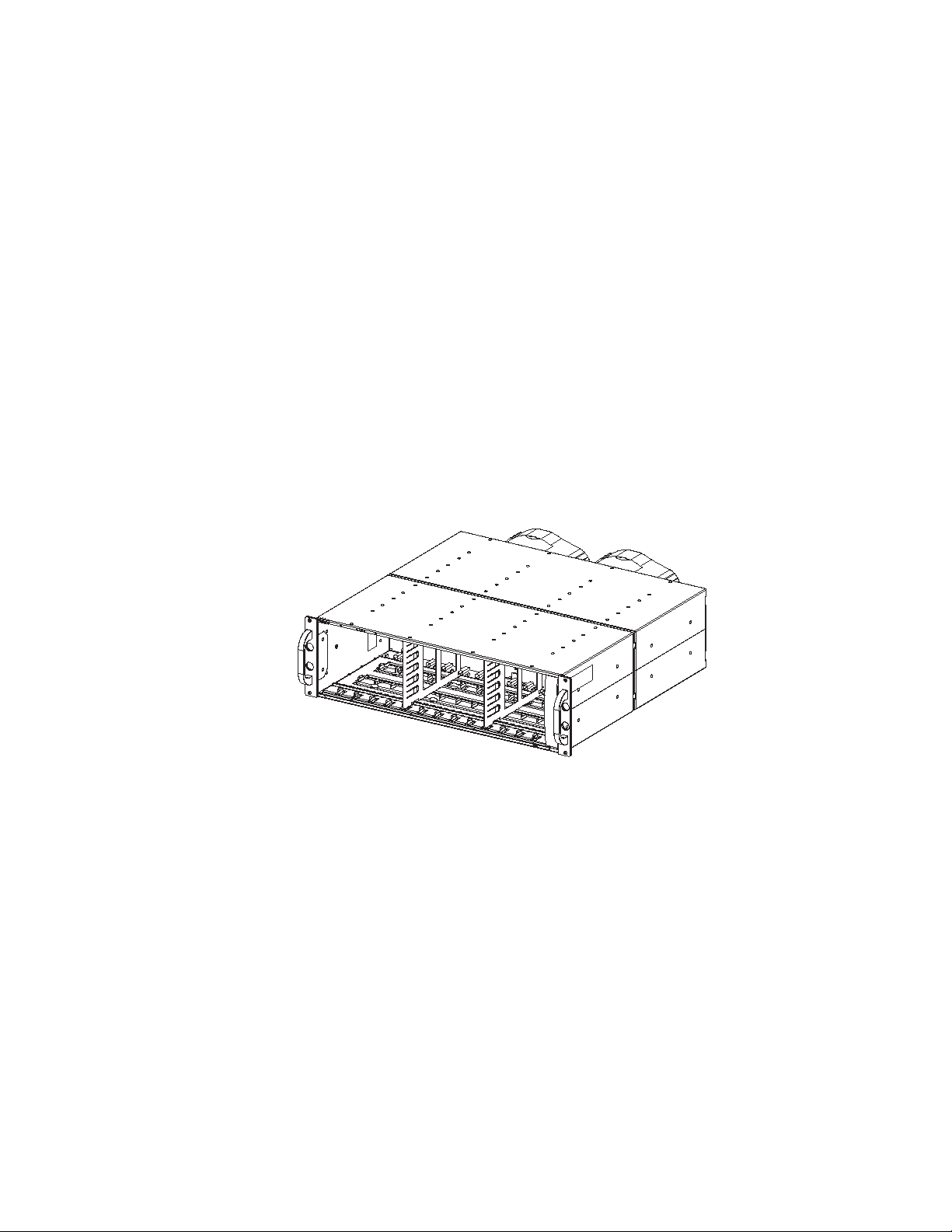
This chapter de scribes of the StorageWorks Enclosure 42 00 family of low voltage
differential (LVD) disk enclosures (see Figure 1–1 and Figure 1–2). These enclosures
support Wide-Ultra and Wide-Ultra2 small computer system interface (SCSI)
protocols. The internal bus supports only LVD drives. The external bus (the enclosure to
the host controller bus) supports either Wide-Ultra2 (LVD) and or Wide-Ultra
single-ended (SE) SCSI pro tocols.
Figure 1–1. Disk Enclosure (Front View)
CXO6854A
Page 14

1–2 Enclosure 4200 Family LVD Disk Enclosures User Guide
Figure 1–2. Disk Enclosure (Rear View)
Disk Enclosure Features
The Model 4214 enclosure supports up to fourteen, 1-inch high, 3.5-inch form factor
hard disk drives. This enclosure is available in either a rack mountable version (4214R)
or in a tower (4214T). A rack (cabinet) mounted enclosure requires a RETMA 3U v ertical
opening (5.25-inches) where a “U” is 1.75-inches.
CXO6912A
The enclosure provides several features, including:
■ Hot-pluggable drives, environmental monitoring unit (EMU), fans, and power
supplies are replaceable without halting SCSI bus data transfers.
■ Pluggable I/O module and SCSI bus cables require quiescing the bus (that is,
stopping all data transfers), but do not require removing power before replacing.
■ Depending upon the host controller, the I/O module is capable of supporting
Wide-Ultra SCSI (LVD) or Wide-Ultra SCSI (SE) bus operations.
■ Depending upon the host-interface controller, an EMU may support the automatic
monitoring of specific enclosure and drive functions.
The enclosure has guides that ensure the drives, EMU, I/O module, and power supplies
(the enclosure elements) align and properly mate with the backplane connectors. A guide
post on the fan ensures that the fan properly mates with the power supply. The elements
and the metal enclosure provide electromagnetic interference (EMI) suppression and
control airflow within the enclosure.
Page 15

SCSI Buses
The enclosure supports only Wide-Ultra2 SCSI, wide (16-bit), internal LVD buses.
Depending on the host interface, the e xternal SCSI b us, the b us from the I/O module to the
host can be either Wide-Ultra or Wide-Ultra2, LVD or SE. The SCSI bus type determines
the length of this bus, and therefore, the maximum cable length. The standard Compaq
cable length of 12 ft (3.7 m) ensures satisfactory operation. As for all SCSI buses, the
shorter the cable, the more efficient the bus operation.
High Availability
The high availability features of the enclosure are a function of the fans and the power
supplies.
Variable Speed Fans
All enclosures have two variable speed fans. In all configurations, the failure of one fan
automatically causes the other fan to operate at a high speed. This ensures that the failure
of a single fan does not disable the enclosure.
Introducing the Enclosure 1–3
Power Supplies
In a single power supply configuration, the failure of a power supply disables the
enclosure. Use the optional redundant power supply configuration to prevent this. In this
configuration, the failure of a single power supply or fan does not disable the enclosure.
Data Integrity
Data integrity could be compromised if data transfers occur when there is no DC power to
the I/O module or the drives, To avoid inducing errors, the power pins on these elements
are longer than the data pins. This ensures that power is always present when a data
transfer occurs.
Page 16

1–4 Enclosure 4200 Family LVD Disk Enclosures User Guide
Status Monitoring and Display
The major status monitoring capabilities of these enclosures include:
■ Displaying the enclosure status on the enclosure LEDs
■ Displaying the element status on the power supply, EMU, drive, and I/O module LEDs
■ Detecting the installation of a fan, power supply, drive, or I/O module
■ Detecting the removal of a fan, power supply, drive, or I/O module
■ Sensing enclosure temperatures
■ Sensing power supply voltage, current, and total power
The EMU user guide describes the functions and features of the EMU.
Enclosure Layout
The physical layout of the enclosure is the same whether in a rack or a tower. The drives
mount in the bays in the front of the enclosure. These bays are numbered from the left
1
(bay
is by the bay number. The drive in bay
forth.
) to the right (bay r, see Figure 1–3). The common method of referri ng to a drive
1
is drive 1, the drive in bay 8 is drive 8, and so
At location
t
are the three enclosure status LEDs.
Page 17
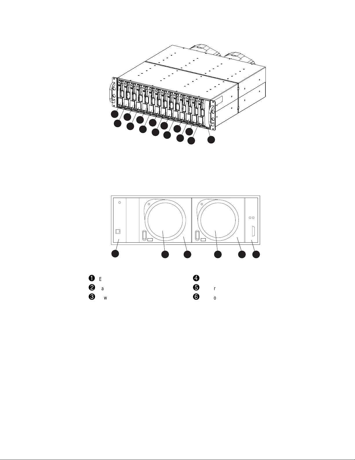
Introducing the Enclosure 1–5
1
3
5
2
4
Figure 1–3. Front Mounted Elements
7
9
6
8
10
11
12
13
14
15
CXO6728A
The I/O module, power supplies, fan s, EMU, and cables mo unt in th e rear of the enclosur e
(see Figure 1–4).
1
1
EMU
2
Fan 1
3
Power Supply Bay 1, or
Fan Mounting Assembly
1. In a single power supply configuration, the fan mounts on the fan mounting assembly.
Figure 1–4. Rear Mounted Elements
1
2 3 4 5 6
CXO6979A
4
Fan 2
5
Power Supply Bay 2
6
I/O Module
Page 18

1–6 Enclosure 4200 Family LVD Disk Enclosures User Guide
Major Elements
The elements each enclosure requires for proper operation include:
■ An EMU
■ Two power supplies, or
1 power supply and 1 fan mounting assembly
■ Two F ans
■ An I/O module
■ A disk drive or disk drive blank in each bay
Element Functions
A full description of the individual elements and their functions can be found in the
individual chapters.
Element Replacement
The methods used to replace an element depend upon se veral factors. The primary factors
are:
■ Could element replacement affect SCSI bus operation?
When the element being replaced does not interrupt data transfer nor affect the
operation of another element, the element is “hot-pluggable.”
If replacement of the element could affect data transfers or the operation of another
element, the element replacement method is “pluggable.”
■ Are there any personal safety issues involved?
Whenever there is an issue inv olving person al safety, such as an electrical hazard, then
the element replacement requires quiescing the SCSI bus and removi ng power from the
enclosure.
T able 1–1 identifies the replacement method and type of replacement for each element.
Table 1–1 CRU Replacement Methods
Element Method
Drive Hot-pluggable
EMU Hot-pluggable
Page 19

Introducing the Enclosure 1–7
Table 1–1 CRU Replacement Methods (Continued)
Element Method
Fan Hot-pluggable
I/O Module Hot-pluggable
Power Supply–Dual Hot-pluggable
Power Supply–Single No Power Applied
SCSI Bus Cables Pluggable
1. In a single power supply configuration, the enclosure is disabled when the power
supply fails.
1
Page 20

With the enclosure installed in a rack or tower it is necessary to:
1. Connect the SCSI bus cables.
2. Apply power.
3. Verify proper operation.
Connecting the SCSI Bus Cables
Connecting the enclosure to a host adapter or SCSI bus controller is simply a matter of
connecting cables to the I/O module. All I/O modules has 68-pin, very high density
computer interface (VHDCI) connectors.
Chapter
2
Starting the Enclosure
Figure 2–1 shows the cable connectors for a single bus configuration.
CAUTION: Connecting or disconnecting a SCSI bus cable while data is being
transferred causes the loss of data.
always
To prevent inducing an error,
disconnecting a cable.
quiesce the SCSI bus before connecting or
Page 21

2–2 Enclosure 4200 Family LVD Disk Enclosures User Guide
1
Primary host controller connector
Figure 2–1. Single Bus Cable Connection
Table 2–1 lists the host array controller cables available. As for any SCSI bus, using the
shortest length cable possible enhances performance.
Table 2–1 SCSI Bus Cables
Description
68-conductor SCSI cable with
2 Vertical Offset VHDCI straight plug connectors
with jack screws
1.8
3.7
11.9
Length
CXO6980A
6
12
39
1
Part NumberMeters Feet
332616-001
332616-002
150214-B21
1
2
CXO6954A
Page 22

Starting the Enclosure 2–3
Table 2–1 SCSI Bus Cables (Continued)
Length
Description
68-conductor SCSI cable with
1 High-Density straight plug connector with jack
screws
1 Vertical Offset VHDCI straight plug connector with
jack screws
1. One cable provided with each enclosure.
2. Use only with Ultra2 SCSI LVD bus operating at speeds of 80 Mb/sec or less.
1.8
3.7
6
12
Part NumberMeters Feet
110941-001
110941-002
CXO6955A
1
Page 23

2–4 Enclosure 4200 Family LVD Disk Enclosures User Guide
Table 2–2 Installing SCSI Bus Cables
1. Stop all SCSI bus data transfers.
2. Align the D-shaped cable connector with D-shaped I/O module connector.
CXO6981A
3. Firmly seat the cable connector on the module connector.
4. Finger tighten the thumbscrews to fully seat the connector.
5. Restart data transfers over the SCSI bus.
Applying Power
There are no disk enclosure power con trol switches. Connecting an AC power cor d from a
power source to the power supply is all that is required. When a power supply has an AC
input, it develops and distributes DC voltages within the enclosure.
Verifying Operation
Applying power causes the elements to begin operating. Check the enclosure status LEDs
in the front, lower right corner (see Figure 2–2). If the display is not exactly as shown,
there is an element error condition. Check the dri ve and en closure status LEDs on the front
and the EMU, power supplies, fans, and I/O module status LEDs on the rear (see
Figure 2–3) to determine the defective element.
Page 24

NOTE: There are two different drive displays for a properly functioning disk.
Figure 2–2. Front Status LEDs
Starting the Enclosure 2–5
CXO6919A
Figure 2–3. Rear Status LEDs
CXO6982A
Page 25

Chapter
3
I/O Module
This chapter discusses the operation and function of the LVD disk enclosure I/O module
(the “module”).
Each enclosure requires an I/O module for operation with a wide (16-bit) controller SCSI
bus. The module is the CRU that connects the enclosure to the host controller through a
68-pin, VHDCI connector and a SCSI bus cable. This module can support a maximum of
14 drives in a single enclosure or on a single-bus.
The host adapter or controller determines whether the external bus is LVD or SE.
Regardless of the host controller type, the internal SCSI bus to the devices is always a
Wide-Ultra2 SCSI LVD bus.
The module is the interface between the host controller (the initiator) the drives and the
EMU. Each enclosure has two SCSI buses. Half of the disks drive bays are on each bus.
The module shown in Figure 3–1 links the two SCSI buses into a single bus.
Page 26

3–2 Enclosure 4200 Family LVD Disk Enclosures User Guide
Figure 3–1. Single-Bus I/O Module
Module Power Protection
CXO6981A
A sensor on the +5 VDC line in the module detects overcurrent conditions. Should th is
error occur, the sensor disconnects the v oltage from the module and the po wer LED is O
(see Figure 3–2). This disables the module until one of the following conditions occurs:
■ The overcurrent condition no longer exists.
■ The defective module is replaced.
A disabled module prevents data transfers between the host controller and the drives, and
the host controller and the EMU. An LED on the module displays the module p ower
status.
Single-Bus Module
This section describes the unique features of the single-bus module. This module (see
Figure 3–1) has one VHDCI connector and two LEDs.
FF
Page 27

SCSI Bus Connectors
The 68-pin VHDCI connector enables yo u to co nfigure the enclosure as single-bus, single
initiator subsystem.
SCSI Bus Termination
A SCSI bus is defined by two bus terminators. The external bus has terminators on the
controller and on the modu le. Each internal bus has a terminator on the module and on the
backplane. The module connects the external bus and the internal bus together. On each
module, there is a green LED (see Figure 3–2) that defines the status of internal bus,
backplane terminator.
Status Displays
See Figure 3–2 for the location of the two green status LEDs, and Table 3–1 for a
description of the LED displays.
I/O Module 3–3
1
Terminator Status LED
Figure 3–2. Single Bus Status LEDs
1
2
Power or Locate LED
2
CXO6983A
Page 28

3–4 Enclosure 4200 Family LVD Disk Enclosures User Guide
Table 3–1 Single-Bus Module LED Displays
LEDs Definition
Operational Status LED Displays
Terminator enabled (LED O
Module power present (LED O
N)
N)
Terminator enabled (LED O
EMU locating module (LED F
Nonoperational Status LED Display
No module power
Module nonoperational
N)
LASHING)
SCSI Address Map
The module assigns a SCSI address to each drive bay in the enclosure using a SCSI
address map. The active map (see Table 3–2) is determined by a combination of:
■ Backplane
■ EMU
■ I/O module
Each disk drive bay and each controller has a SCSI bus ID. The factory-assigned disk
enclosure addresses are shown in Table 3–2.
Table 3–2 Disk Enclosure Bay Addresses
Bay1234567891011121314
SCSI ID00 01 02 03 04 05 08 09 10 11 12 13 14 15
Replacing an I/O Module
Replacing an I/O module requires you to order a replacement using the spare part number
(see Chapter 6, “Replacing CRUs”).
Each I/O module replacement kit contains detailed replacement instructions.
Page 29

Chapter
4
Disk Drives
The enclosure supports Compaq hot-pluggabl e, Wide-Ultra 2 S CSI, LVD disk drives. This
chapter describes the disk drive features, functions, and characteristics.
The 14-disk enclosure supports 1.0-inch, 3.5-inch form factor drives mounted in a carrier
(see Figure 4–2).
CAUTION: Controlling airflow within the enclosure requires installing a disk
drive or a drive blank in each drive bay.
To avoid overheating, never remove more than 1 drive or drive blank from an
operating enclosure at the same time.
Figure 4–1. Typical 1-Inch Disk Drive
CXO6695A
Page 30

4–2 Enclosure 4200 Family LVD Disk Enclosures User Guide
CXO6695A
Status Reporting
The three disk drive status LEDs (see Figure 4–2) define the operational status of each
drive. To determine the drive status you must observe all three LEDs (see Table 4–1).
Drive Activity LED
This green LED indicates the drive
activity, that is drive being accessed,
spinning-up, and so forth.
On-line LED
This green LED indicates if the drive is
operational, non-operational, part of
RAID set, a replacement drive, a spare
drive, or a rebuilding RAID drive.
Drive Failure LED
This amber LED indicates the drive
status as either operational (O
failed (O
N).
FF) or
Figure 4–2. Disk Drive LEDs Display
Disk Status
The drives have two green and one amber LEDs that are either ON, OFF, or FLASHING.
Since the status LED displays are easily interpreted, they are the most commonly used
indicators of drive status. The symbols for these conditions are shown in Table 4–1.
Table 4–1 Disk LED Status Displays
LEDs Status
Operational Status
Drive not being accessed
The drive is a replacement drive to be rebuilt or the drive is an inactive spare disk or the
SCSI controller cannot control LED. The drive is Operational
D
O NOT REPLACE DRIVE
Page 31

Table 4–1 Disk LED Status Displays (Continued)
LEDs Status
Operational Status (Continued)
Drive not being accessed
Drive is being rebuilt or Array Capacity expansion in progress
Drive Operational
D
O NOT REPLACE DRIVE
Drive not being accessed
Drive configured as part of an array
Drive Operational
D
O NOT REPLACE DRIVE
Drive selected using the Array Configuration Utility.
D
O NOT REPLACE DRIVE
Drive is being accessed or spinning-up.
Replacement drive to be rebuilt, or the drive is an inactive spare disk, or drive is
spinning up during POST, or the SCSI controller cannot control LED. The drive is
Operational
D
O NOT REPLACE DRIVE
Drive is being accessed
Drive is being rebuilt or Array Capacity expansion in progress
Drive Operational
D
O NOT REPLACE DRIVE
Drive is being accessed
Drive configured as part of an array
Drive Operational
D
O NOT REPLACE DRIVE
Fault Status
Drive not being accessed
Drive failure
Drive failure
OK
TO REPLACE DRIVE
Disk Drives 4–3
Page 32

4–4 Enclosure 4200 Family LVD Disk Enclosures User Guide
Drive Power
Backplane overcurrent sensors monitor the +5 VDC and +12VDC drive voltages. When
there is a drive overcurrent condition the sensor disconnects the voltage from the drive.
This disables the drive, ensuring that no data is written to it. The driv e is disabled until one
of the following conditions occurs:
■ The defective drive is replaced.
■ The overcurrent condit ion no longer exists.
Drive Blank
To maintain the proper enclosure airflow there must be a drive or a drive blank in each
drive bay. The function of the drive blank (see Figure 4–3) is to control airflow within a
bay.
Figure 4–3. Drive Blank
CXO6824A
Page 33

Replacing a Disk
Replacing a disk requires you to order a replacement using the spare part number (see
Chapter 6, “Replacing CRUs”).
The disk replacement kit contains detailed replacement instructions.
CAUTION: Removing more than one disk drive at a time can cause the enclosure to
overheat. Never remove more than one disk drive at a time.
NOTE: Removing a drive from the enclosure affects the airflow in the enclosure. This can result
in an overheating condition that could affect disk reliability. Compaq recommends installing a
disk drive of equal or greater capacity, or a disk drive blank as soon as possible.
Disk Drives 4–5
Page 34

Chapter
5
Enclosure Power and Cooling
This chapter describes the function and general operation of the enclosure power supply
and fans. See Figure 5–1 for major component locations.
1
1
6
5
Power Supply Element
2
AC Input Connector
3
Module Latch
4
Status LED
3
2
Figure 5–1. Power Supply and Fan Assembly Components
4
5
CXO6809A
5
6
Fan Tabs
Fan Element
Page 35

5–2 Enclosure 4200 Family LVD Disk Enclosures User Guide
Enclosure Power
The power supply and fan assembly mount in the rear of the enclosure. The supply is
auto-ranging and operates on an AC input voltage of 100 to 240 VAC ±10%, 50 to 60 Hz
± 5% (90 to 264 VAC, 47 to 63 Hz).
There are three DC outputs:
■ +5 VDC for the EMU, I/O module, backplane, and drives
■ +12.3 VDC for the drives.
■ +12.5 VDC for the fans.
The nominal output of each supply is 377W, with a peak output of 425W. Either power
configuration, single or dual, can support an enclosure with a full complement of disks,
fans, EMU, and I/O module.
■ A single power supply, the standard configuration, supports sequential drive spin-up.
■ The Compaq recommended dual po wer suppl y configu ration can support simultaneous
drive spin-up.
The power supply circuitry provides protection against:
■ Overloads
■ Short circuits
■ Thermal protection against cooling system faults.
Power supply status and diagnostic information is reported to the EMU using the voltage,
current, and temperature signals.
See Appendix B, “Specifications,” for the enclosure power specifications.
Power Options
The enclosure can accommodate one or two power supplies. One power supply is
sufficient to power the enclosure with a full complement of drives.
NOTE: Installing two power supplies, a redundant power configuration, eliminates the
power supply as a single point of enclosure failure. This is the preferred,
high-availability configuration.
Page 36

The fan mounting assembly is the element for mounting the second fan. This element has
no power circuitry. It does contain a circuit board for processing signals to and from the
fan.
Temperature Sensing
The power supply temperature sensor provides a temperature range signal to the EMU.
The EMU can use this signal to set the fan speed.
Fan Interface
The fan mounts on the rear of the power su pply. A power supply connector is the interface
between the fan and the enclosure. The interface signals include:
1. Fan speed control from the EMU
2. Fan speed to the EMU through the power supply
3. Power supply high-speed enable
4. Fan operating voltage
Enclosure Power and Cooling 5–3
Fans
The power supply-mounted fans cool the enclosure by circulating air through the
enclosure and elements. The rate at which air moves, the airflow, determines the amount
of cooling. This airflow is a function of fan speed (rpm). These fans, under the control of
the EMU or the associated power supply, can operate at multiple speeds. This ensures that
when the enclosure temperature changes, the fans can automatically adjust the airflow.
Should a fan fail, EMU and po wer supply circuitry automatically increase the speed o f the
operational fan to high speed. Simultaneously , the error condition is reported to the user in
several ways.
NOTE: The failure of the power supply 12.5 VDC circuit disables the associated fan.
Page 37

5–4 Enclosure 4200 Family LVD Disk Enclosures User Guide
Status Reporting
The green status LED on the fan displays the status of either the power supply or the fan.
See Table 5–1 for definitions of the LED displays.
Table 5–1 Power Supply and Fan Status Displays
LED Status
Operational Status
Both the power supply and the fan are operational.
The EMU is locating either the power supply or the fan.
Nonoperational Status
Either the power supply or the fan is nonoperational.
For a fan problem, the other fan runs at high-speed.
Replacing a Power Supply or Fan
Replacing a power supply or fan requires that you to order a replacement using the spare
part number (see Chapter 6, “Replacing CRUs”).
Each power supply or fan replacement kit contains detailed replacement instructions.
Page 38

Each replacement CRU kit contains detailed replacement instructions. This chapter
describes the general replacement procedures.
Ordering a Spare CRU
Ordering a replacement CRU requires the Compaq spare part number. This number is
located in the upper-right corner of the product label (see
Chapter
6
Replacing CRUs
1
, Figure 6–1).
CXO6879A
Figure 6–1. Typical Product Label
The first six characters of the part number identify the CRU. The last three define the
revision level.
1
Page 39

6–2 Enclosure 4200 Family LVD Disk Enclosures User Guide
ESD Protection
When you replace a CRU, you must take precautions to prevent the possibility of
electrostatic discharge (ESD) damaging sensitive electronic items.
1. Always transport and store CRUs in a static-safe container.
2. Do not remove the CRU from the static-free container until you are ready to install it.
3. Avoid touching the CRU connector p i ns, leads, or circuitry.
Basic Replacement Procedures
The procedures in Table 6–1 apply to all the CRU replacement procedures.
CAUTION: The hot-pluggable power supplies, fans, EMU, and drives
quiescing the SCSI bus, that is halting all data transfers, the SCSI bus.
Replacing an I/O module or a SCSI bus cable a
lways requires
do not
require
quiescing the SCSI bus.
Table 6–1 Common Replacement Procedures
1.
Always
transport and store CRUs in a static-safe container.
Before starting the replacement procedure
CAUTION: T o pre ven t ESD d amage,
circuitry.
2. Remove the defective CRU from the enclosure.
3. Remove the replacement CRU from the static safe container and verify that it is a compatible
replacement (refer to Figure 6–1).
4. Align the CRU with the enclosure guide slots.
5. Slide the CRU into the enclosure until it is against the backplane connector.
6. Fully seat the CRU in the enclosure and verify that if operating properly.
After replacing the CRU
7. Place the defective CRU in the static safe container for shipment.
never
touch the CRU connector pins , leads , or
Page 40

Replacing CRUs 6–3
CAUTION: An assembled enclosure (all elements installed) weighs more than 65 lb
(29.5 kg). Moving the assembled enclosure requires a minimum of two individuals.
To safely and easily install the enclosure requires removing the drives, power supply
and fans, EMU, and I/O module. This reduces the enclosure weight to approximately
24 lb (11.3 kg). Even though a single person can lift this weight, the physical size
makes it very difficult to install.
Compaq requires a minimum of two individual to install an empty enclosure in a rack
or tower.
Page 41

6–4 Enclosure 4200 Family LVD Disk Enclosures User Guide
Replacing a Drive with a Drive Blank
Should a disk drive fail you may wish to replace it with a drive blank using the procedure
in Table 6–2.
CAUTION: Removing more than one disk drive at a time can cause the enclosure to
overheat. Never remove more than one disk drive at a time.
NOTE: Removing a drive from the enclosure affects the airflow in the enclosure. This can result
in an overheating condition that could affect disk reliability. Compaq recommends installing a
disk drive of equal or greater capacity, or a disk drive blank as soon as possible
Table 6–2 Installing a Drive Blank
1. Press in on the Ejector Button 1 and pivot the Release Lever 2 to the full, open positions.
1
2
CXO6826A
2. Pull out on the drive until it is disconnected from the backplane connector.
D
O NOT REMOVE THE DRIVE FROM THE ENCLOSURE WHILE THE MEDIA IS ROTATING.
3. When you are sure that the disk is no longer spinning, remove the drive from the enclosure.
Page 42

Table 6–2 Installing a Drive Blank (Continued)
4. Insert the drive blank part-way into the enclosure.
CXO6824A
5. Firmly press in on the drive bank to seat it in the connector.
Replacing CRUs 6–5
Page 43

FCC Class B Certification
This equipment has been tested and found to com ply with the limits for a Class B digital
device, pursuant to Part 15 of the FCC rules. These limits are designed to provide
reasonable protection against harmful interference in a residential installatio n.
Any changes or modifications made to this equipmen t may void the users authority to
operate this equipment.
This equipment generates, uses, and can radiate radio frequency energy and, if not
installed and used in accordance with the instructions, may cause harmful interference to
radio communications. Howe v er , th ere is no guarantee that interferen ce will not occur in a
particular installation. If this equipment does cau se harmful interference to radio or
television reception, which can be determined by turning the equipment off and on, the
user is encouraged to try to correct the interference by one or more of the following
measures:
■ Reorient or relocate the receiving antenna.
Appendix
A
Regulatory Notices
■ Increase the separation between the equipment and receiver.
■ Connect the equipment into an outlet on a circuit different from that to which the
receiver is connected.
■ Consult the dealer or an experienced radio/TV technician for help.
Page 44

A–2 Enclosure 4200 Family LVD Disk Enclosures User Guide
Country-Specific Certifications
Compaq tests all the electronic products for compliance with country-specific regulatory
requirements either as an individual item or as par t of an assembly. The pr odu ct label (see
Figure A–1) specifies the regulations with which the product complies.
NOTE: Elements without an individual product certification label are qualified as part
of the
next higher
assembly (for example, enclosure, rack, or tower).
1
4
2
1
Taiwan EMC and Safety BCIQ
2
Australia C-Tick EMC
3
Europe: CE-Mark EMC and Safety
Declaration
4
Denmark Safety (DEMCO)
5
USA Underwriter’s Laboratory component
recognition
6
Finland Safety (FIMKO)
Figure A–1. Typical Product Label Country-Specific Certifications
3
7
Norway Safety (NEMKO)
8
Sweden Safety (SEMK)
9
Japan VCCI Class B
-
Canada CSA
;
Germany TÜV Product services recognition
<
USA FCC Class B
12
7
6
5
8
11
10
9
CXO6892A
NOTE: The certification symbols on the label depend upon the certification level. For example,
the FCC Class A certification symbol is not the same as the FCC Class B certification symbol
<
). Other symbols that change based on the product or certification level are 1, and 9.
(
Page 45

This appendix defines the physical, environmental, and power specifications and the
environmental specifications of the disk enclosure and the elements.
Physical Specifications
CAUTION: The weight of the disk enclosure with the elements installed
always requires at least two individuals to move it. Compaq recommends
using fork lifts or hand trucks to move an enclosure in its shipping container.
Figure B–1 and Figure B–2 show the dimensions for vertical and horizontal orientations.
Table B–1 defines the dimensions and weights of the enclosure. Table B–2 defines the
dimensions of the EMU, fans, I/O module, and power supply.
Appendix
B
Specifications
Page 46

B–2 Enclosure 4200 Family LVD Disk Enclosures User Guide
3
Figure B–1. Dimensions–Vertical Orientation
1
2
CXO6965A
3
Figure B–2. Dimensions–Horizontal Orientation
1
2
CXO6898A
Page 47

Specifications B–3
Table B–1 14-Disk Enclosure Physical Specification
Horizontal Orientation (see Figure B–1) Vertical Orientation (see FigureB–2)
Empty Installed Shipping Carton Shipping Carton and
Pallet
1
5.16 in (13.1 cm) 5.16 in (13.1 cm) 25.25 in (64.1 cm) 30.25 in (76.8 cm)
2
17.625 in (44.8 cm) 17.625 in (44.8 cm) 23.5 in (59.7cm) 40.0 in (101.6 cm)
3
19.875 in (50.5cm) 19.875 in (50.5cm 12.5 in (31.8 cm) 24 in (61 cm)
Weight 24 lb (11 kg) 68 lb (31 kg) 96 lb (44 kg) 108 lb (49 kg)
Table B–2 Element Physical Specifications
Vertical Orientation (see Figure B–2) Horizontal Orientation (see FigureB–1)
Installed Shipping Carton
Environmental Monitoring Unit (EMU)
1
4.5 in (11.4 cm) 8.5 in (21.6 cm)
2
9.5 in (24.1 cm) 13.0 in (33.0 cm)
3
1.375 in (3.5 cm) 4.5 in (11.4 cm)
Weight 1.3 lb (0.6 kg) 2.3 lb (1.0 kg)
Variable Speed Fan (without power supply)
1
5.5 in (14.0 cm) 7.5 in (19.0 cm)
2
3.25 in (6.4 cm) 8.75 in (22.2 cm)
3
6.25 in (15.9 cm) 8.0 in (20.3 cm)
Weight 1.0 lb (0.5 kg) 2.0 lb (0.9 kg)
I/O Module
1
4.5 in (12.7 cm) 8.5 in (21.6 cm)
2
9.5 in (24.1 cm) 13.0 in (33.0 cm)
3
1.625 in (4.1 cm) 4.5 in (11.4 cm)
Weight 1.3 lb (0.6 kg) 2.3 lb (1.0 kg)
Page 48

B–4 Enclosure 4200 Family LVD Disk Enclosures User Guide
Table B–2 Element Physical Specifications (Continued)
Vertical Orientation (see Figure B–2) Horizontal Orientation (see FigureB–1)
Installed Shipping Carton
Power Supply (without fan)
4.5 in (12.7 cm) 11.5 in (29.2 cm)
1
2
6.25 in (15.9 cm) 13.0 in (33.0 cm)
3
Weight 4.0 lb (1.8 kg) 6.0 lb (2.7 kg)
9.5 in (24.1 cm) 16.75 in (42.6 cm)
Environmental Specifications
To ensure optimum product operation you must maintain the operational environmental
specifications listed in Table B–3. Especially critical is the ambient temperature.
Table B–3 Operating Specifications
Ambient Temperature: 10°C to +35°C (+50°F to +95°F) with an average rate of change of 1°C/hour
maximum and a step change of 3°C or less
Maintaining the
operating temperatures supports disk drive manufacturer’s MTBF specifications.
Relative Humidity: 40% to 60% (noncondensing) with a step change of 10% or less (noncondensing)
Air Quality: Not to exceed a maximum of 500,000 particles, 0.5 micron or larger, per cubic foot of air.
Heat Dissipation: 1600 BTUs per hour
optimum ambient temperature
within the specified range ensures that the internal
When shipping this product, or placing it in short term storage, Compaq recommends
maintaining the environmental conditions listed in Table B–4.
Table B–4 Shipping or Short Term Storage Specifications
Ambient Temperature: –40°C to +66°C (–40°F to +150°F)
Relative humidity: 10% to 80% noncondensing
Altitude: 15,240 m (50,000 ft)
Page 49

Power Specifications
Table B–5 defines the AC and DC power specifications for the disk enclosure power
supplies.
Table B–5 AC and DC Power Specifications
Frequency (±5%) 47 Hz 50 to 60 Hz 63 Hz
Voltage (±10%) 90 VAC 100 to 240 VAC 264 VAC
Power
Initial Voltage 5.10 VDC +5.15 VDC 5.20 VDC
Steady State Current
Initial Voltage 12.13 VDC 12.25 VDC 12.37 VDC
Steady State Current
Initial Voltage 12.25 VDC 12.50 VDC 12.75 VDC
Steady State Current
Specifications B–5
AC Power Specifications
Range
Minimum Nominal Maximum
DC Power Specifications
377 W 475 W
+5 VDC
20.0 A 28.0 A
+12 VDC (Disks)
20.0 A 31.5 A
+12.5 VDC (Fans)
2.5 A
Page 50

Glossary
The terms in this glossary are either unique to the disk enclosure, or are common
StorageWorks terms.
ambient temperature The air temperature in an area where a system is installed. Also referred
to as rack or enclosure intake air temperature.
bay The physical location of a dri ve in an enclosure. Each bay is numbe red to
define its location. The bay number may or may not be the same as the
SCSI bus ID.
carrier The container in which storage devices are mounted to form CRUs.
Carriers are available in 3.5-inch form-factors for both low-profile
(1.0-in) and half-height (1.6-in) disks.
CRU Customer replaceable unit. An enclosure element that the customer can
replace without using special tools or techniques.
device The targets, initiators, hubs, converters, and bus expanders, and similar
devices interconnected to form a SCSI bus. Connectors, expanders, and
hubs do not use a SCSI bus ID.
See also nodes.
disk enclosure A Compaq enclosure dedicated to supporting disk drives. Such an
enclosure includes the power supplies, fans, I/O modules, and an EMU.
Page 51

GL–2 Enclosure 4200 Family LVD Disk Enclosures User Guide
drive blank A carrier that is required to control airflow within the enclosure whenever
there is less than a full complement of disk drives in an enclosure. The
only function of a passive drive blank is to control airflow within the disk
enclosure.
dual power See redundant power configuration.
element An object in an enclosure such as an EMU, power supply, disk, fan, I/O
module, and so forth. The object can be controlled, interrogated, or
described by the enclosure services process.
EMU Environmental monitoring unit. An element which monitors the status of
an enclosure including the po wer , air temperature, fan status, and so forth.
It detects problems and displays and reports these conditions to the user
and the controller. In some cases, corrective actions are implemented.
enclosure A chassis containing a set of disk drives, power supplies, fans, an EMU,
I/O modules, and so forth.
fan An airflow element mounted in a StorageWorks enclosure.
host The primary or controlling computer (in a multiple computer network) to
which storage is attached.
hot-pluggable An element that can be replaced without removing power from the
enclosure.
CAUTION: If removing the element interrupts the SCSI bus you
cannot use this method. You must quiesce the bus and use the
pluggable replacement method.
NOTE: The array controller must support this replacement method.
I/O module An element that integrates the enclosure bus with either an 8-bit
single-ended, 16-bit single-ended, or 16-bit differential SCSI bus.
LED Light emitting diode. A diode that illuminates to define the status. The
standard states are O
N, OFF, or FLASHING.
Page 52

Glossary GL–3
pluggable A method of element replacement whereby the complete system remains
on-line during element removal or insertion. There is no data transfers
over the enclosure buses during removal or insertion of an element (the
bus is “quiesced”). No booting or loading of code is permitted except on
the element being inserted. User applications that are not dependent upon
the elements on the affected SCSI bus are not noticeably impacted.
See also hot-pluggable.
power supply The enclosure element that develops that DC voltages for operating the
enclosure elements from either an AC or DC source.
quiesce To make a bus inactive or dormant. For example, you must quiesce SCSI
bus operations when replacing an element without removing power.
See also pluggable.
rack A floor-standing structure primarily designed for, and capable of,
supporting equipment. All racks provide for the mounting of panels. (per
EIA Standard RS-310-C).
RAID Redundant array of independent disks. A set of storage techniques
devised to increase the performance and availability of a storage
subsystem.
redundant power
configuration
RETMA mounting
pattern
SCSI Small computer system interface (SCSI). An ANSI interface which
SCSI bus An unbroken path consisting of conductors (in cables or on backplanes)
A capability of StorageW orks cabinet and enclosures to ensure there is no
single point of power failure. ( 1) Fo r a cabinet tw o AC power sources an d
two power conditioning units distributed primary and redundant AC
power to enclosure power supplies. (2) For an enclosure, the primary and
redundant enclosure power supplies ensure the DC power is available
even when there is a failure of one supply, one AC source, or one power
conditioning unit. Implementin g the redundant power configuration
provides protection against the loss or corruption of data.
The repeating mounting pattern in a vertical mounting rail established by
Radio, Electronics, and Television Manufacturers Association, the
predecessor of the Electronics Industry Association (EIA).This pattern
repeats every 1 .75 in and is referred to as a unit. Therefore, a 3U pattern is
5.25 inches; a 4U pattern is 7.00 inches, and so forth.
defines the physical and electrical parameters of a parallel I/O b us used to
connect computers and a maximum of 16 bus elements.
and connectors. Every bus must have two terminators, one at each end.
Page 53

GL–4 Enclosure 4200 Family LVD Disk Enclosures User Guide
SCSI ID (1.) The bit-significant representation of the SCSI addressing referring to
one of the signal lines numbered 0 through 7 for an 8-bit bus or 0 through
15 for a 16-bit bus. Also referred to as “tar get ID”. (2.) The unique device
identification number assigned to each target or initiator on a single SCSI
bus. The valid address range for a wide bus is 0 through 15.
spin-up The process that begins when power is applied to a storage drive, and
ends when the drive is determined to be operational and ready for data
transfer operations.
StorageWorks The Compaq set of enclosure products that allows customers to design
and configure their own storage subsystem. Elements include power,
packaging, and interconnections in a StorageWorks enclosure. Storage
devices, power supplies, I/O modules, EMUs, and array controllers may
be integrated therein to form storage subsystems. System-le vel enclosures
to house the enclosures are also included.
terminator Interconnect elements that form the ends of the transmission lines in bus
segments. A SCSI domain must ha ve at least one segment and therefore at
least two terminators, except for special cases where the electrical
transmission lines are very short and only on e termination or pull–up is
required.
tower A freestanding, floor mounted unit containing a disk enclosure in the
vertical orientation. This unit can function as a stand-alone storage
subsystem.
units The modular unit “U” on which panel heights is based on the vertical
RETMA mounting pattern of 1.750 inches (44.45 mm). (Per EIA
Standard RS-310-C.)
VHDCI Very High Density Computer Interconnect. A 68-pin interface with
connectors on 0.8 mm centers. Required for Wide-Ultra2 SCSI
configurations.
Wide-Ultra SCSI A SCSI bus that can operate either as an LVD or SE bus. This bus
transfers data at rates up to 40 MB/s when using the LVD protocol. When
using SE the maximum transfer rate is 20 MB/s.
Wide-Ultra2 SCSI A wide SCSI bus that transfers data at rates up to 80 MB/s when
operating using the LVD protocol. There is no provision for this bus to
operate in the narrow mode.
Page 54

Index
A
airflow 1–2, 4–5, 6–4
B
backplane 1–2
bays, See enclosure
C
CRUs
ordering
replacement procedures
replacing
6–1
6–1
D
data integrity 1–3
data tran s f e r s
disk drive
blank
detecting installation
detecting removal
disk drives
DC power
drive blank
installing
overcurrent sensors
power
replacing
spin-up
1–3
1–6
1–2, 1–6, 4–1
5–2
4–4
1–4
4–4
4–5
1–4
4–4
1–4
6–2
sequential
simultaneous
status
status LEDs
displays
drive activity
drive failure
on-line
5–2
5–2
4–2
4–2
4–2
4–2
4–2
4–2
E
electromagnetic interference. See EMI.
1–2
EMI
1–2, 1–6
EMU
DC power
monitoring functions
enclosure
air flow
bay numbering
bays
cooling
features
front view
installation
layout-front
layout-rear
overheating
physical specifications
5–2
1–2
1–4, 6–3
5–3
1–4
1–4
5–3
1–2
1–1
6–3
1–5
1–5
4–5, 6–4
B–1, B–3, B–4
Page 55

I–2 Enclosure 4200 Family LVD Disk Enclosures User Guide
rear view 1–2
safety precautions
6–3
weight
environmental monitoring unit. See EMU.
environmental specifications
operating
shipping
storage
B–4
B–4
B–4
6–3
B–4
F
fans 1–2, 1–6, 5–1, 5–3
DC power
detecting installation
detecting removal
guide post
replacing
speed
speed control
status
LED
LED display
tabs
FCC Class B Certification
functions
5–2
1–4
1–4
1–2
5–4
5–3
5–3
5–1
5–4
5–1
A–1
1–6
H
high availability 1–3
data integrity
1–3
fans
power supply
host adapter. See SCSI bus controller.
hot-pluggable
1–3
1–3
1–2, 1–6, 4–1, 6–2
I
I/O module 1–2, 1–6, 2–1, 3–1
current sensor
data transfer disable
DC power
detecting installation
detecting removal
power disco nnect
power status LED
replacing
3–2
3–2
5–2
1–4
1–4
3–2
3–2
3–4
SCSI Bus connectors
displays
location
3–2
3–4
3–3
single-bus
status LEDs
VHDCI connector
3–3
3–3
L
labels
certification
product
low voltage differential, See LVD
1–1, 4–1
LVD
A–2
6–1
P
personal safety 1–6
physical specifications
B–3
EMU
B–3
fans
I/O module
power supply
pluggable
2–4, 5–1
power
configurations
Compaq recommended
dual. See Compaq recommended.
high-availability. See Compaq
options
redundant. See Compaq recommended.
single
single supply
specifications
power supply
AC input
connector
frequency range
voltage range
component locations
DC
distribution
outputs
B–3
B–4
1–2, 1–6
5–2
recommended.
5–2
5–2
1–3
B–5
1–2, 1–3, 1–6, 5–1
5–1
5–2
5–2
5–1
5–2
5–2
Page 56

Index I–3
detecting installation 1–4
detecting removal
diagnostic information
fan interface
module latch
power rat ings
protection
replacing
status
temperature sensing
product certification
5–2
5–4
5–1, 5–4
LED
LED display
reporting
1–4
5–3
5–1
5–2
5–4
5–2, 5–4
5–3
A–2
Q
quiescing 1–6
R
replacement
affect on SCSI bus operation
methods
1–6
disk drive
dual power supplies
EMU
fan
hot-pluggable
I/O module
pluggable
SCSI bus cables
single power supply
1–6
1–6
1–7
1–6
1–7
1–6, 1–7
1–7
S
safety 1–6
1–1
SCSI
SCSI bus
1–1, 2–1
cable length
cables
connecting
disconnecting
installing
part numbers
controller
quiescing
1–3
1–2, 1–5, 1–7, 2–1, 3–1
2–1
2–1
2–4
2–2
2–1
1–2, 2–1, 6–2
5–2
1–7
1–7
1–6
single bus configuration
termination
external bus
internal bus
status LED
VHDCI
connectors
SCSI bus addresses
address map
drive bays
sensing
enclosure temperatures
power supply
current
total power
voltage
single bus configuration
single-ended, See SE.
slots. See bays.
small computer system interface. See SCSI.
status displays
disk drives
1–4
EMU
enclosure
I/O module
power supply
status monitoring
3–3
3–3
3–3
2–1
2–1, 3–1
3–4
3–4
1–4
1–4
1–4
1–4
1–4
1–4
1–4
1–4
1–4
2–1
1–4
2–1
U
Ultra SCSI bus 1–1
external
SE
Ultra2 SCSI bus
controller
internal
LVD
1–1, 3–1
1–1, 1–2, 3–1
1–1, 4–1
3–1
1–1, 3–1
1–2
V
verifying operation 2–4
disk drive status LEDs
enclosure status LEDs
very high density computer interface. See SCSI
bus, VHDCI.
2–5
2–4, 2–5
 Loading...