

Page 1

COMPAQ DESKPRO 386
Personal Computer
MAINTENANCE AND
SERVICE GUIDE
Page 2

Page 3

NOTICE
The information in this guide is subject to change without notice.
COMPAQ COMPUTER CORPORATION SHALL NOT BE LIABLE FOR TECHNICAL OR EDITORIAL ERRORS OR OMISSIONS CONTAINED HEREIN; NOR
FOR INCIDENTAL OR CONSEQUENTIAL DAMAGES RESULTING FROM
THE FURNISHING, PERFORMANCE, OR USE OF THIS MATERIAL.
This guide contains information protected by copyright. No part of this guide
may be photocopied or reproduced in any form without prior written consent
from Compaq Computer Corporation.
© Copyright 1988 by Compaq Computer Corporation.
All rights reserved. Printed in the U.S.A.
COMPAQ®, COMPAQ DESKPRO®, COMPAQ DESKPRO 286®, COMPAQ PORTABLE II®,
COMPAQ DESKPRO 386®, COMPAQ PORTABLE III®, COMPAQ DESKPRO 386/20®,
COMPAQ PORTABLE 386®, COMPAQ DESKPRO 386s®, COMPAQ DESKPRO 386/25,
COMPAQ DESKPRO 386/20e, and COMPAQ SLT/286 are trademarks of
The software described in this guide is furnished under a license agreement
of nondisclosure. The software may be used or copied only in accordance with
the terms of the agreement.
Microsoft®, MS®, and MS-DOS® are trademarks of Microsoft Corporation.
Product names mentioned herein are used for identification purposes only and
may be trademarks and/or registered trademarks of their respective companies.
MAINTENANCE AND SERVICE GUIDE
COMPAQ DESKPRO 386 Personal Computer
Compaq Computer Corporation.
MS® OS/2 is a product of Microsoft Corporation.
Third Edition (February 1988)
Second Edition (June 1987)
First Edition (August 1986)
Assembly Number 108033-003
Text Number 108035-003
Addendum 108431-001 (November 1988)
Compaq Computer Corporation
®
Registered United States Patent and Trademark Office.
Page 4

ii
WARNING
This equipment has been certified to comply with the limits for a Class
B computing device, pursuant to Subpart J of Part 15 of FCC Rules.
Only peripherals (computer input/output devices, terminals, printers,
etc.) certified to comply with the Class B limits may be attached to this
computer. Operation with noncertified peripherals is likely to result in
interference to radio and TV reception.
WARNING
This equipment generates, uses, and can radiate radio frequency
energy. If not installed and used in accordance with the manufacturer’s instructions, if may cause interference with radio and television
reception. This equipment has been certified to comply with the limits
for a Class B computing device, pursuant to Subpart J of Part 15 of
FCC Rules, which are designed to provide reasonable protection
against such interference. If this occurs, the user will be required
to take whatever measures may be necessary to eliminate the interference. In attempting to do so, the user should:
□ Reorient the receiving antenna.
□ Relocate the computer with respect to the receiver with which it
interferes..
□ Plug the computer into a different AC receptacle so that the com-
puter and the receiver with which it interferes are on different
branch circuits.
If necessary, consult an Authorized COMPAQ Computer Dealer or an
experienced radio/television technician for additional suggestions.
Page 5

NOTICE
Compaq Computer Corporation requires that all peripheral devices be connected
to this computer via shielded cables with metal RFI/EMI connector hoods.
WIRE TYPE: Multipaired overall-shielded; Belden #98XX; Alpha #54XX;
or equivalent.
CONNECTOR
HOOD:
It is important that the chassis ground of any peripheral device be connected
to the computer chassis. An Alpha #1221 flat-braided strap is sufficient. This
strap is not necessary if the shielded cable connects the two chassis.
RFI/EMI metal shield; AMP #74517X-X; or equivalent.
iii
Page 6

iv
PREFACE
The COMPAQ DESKPRO 386 PERSONAL COMPUTER MAINTENANCE
AND SERVICE GUIDE is a troubleshooting, maintenance, and repair guide
that can be used as a reference when servicing the COMPAQ DESKPRO 386
Personal Computer.
All troubleshooting and repair procedures are detailed to allow subassembly/module-level repair only.
CAUTION
Because of the complexity of the individual boards and subassemblies,
Compaq Computer Corporation strongly recommends that you do not
attempt to make field repairs at the component level.
Page 7

SUMMARY OF TEXT
The COMPAQ DESKPRO 386 MAINTENANCE AND SERVICE GUIDE con-
tains the following eight chapters:
Chapter 1 OPERATING AND PERFORMANCE SPECIFICATIONS pro-
vides operating and performance specifications for the COMPAQ
DESKPRO 386 Personal Computer.
Chapter 2 POWER-ON SELF-TEST (POST)/PROBLEM ISOLATION describes
the internal system diagnostics programs that run automatically when you turn on the system. A flowchart is provided for
identifying and correcting problems that can occur during the
Power-On Self-Test procedure.
Chapter 3 SETUP PROGRAM describes the purpose and function of the
SETUP program, including explanations about when you must
run the SETUP program and when the system prompts you to
run the SETUP program.
Chapter 4 ADVANCED DIAGNOSTICS PROGRAM describes the use and
function of the COMPAQ ADVANCED DIAGNOSTICS program
and provides a detailed description of the various diagnostics
routines.
Chapter 5 ERROR MESSAGES AND CODES lists and describes the Power-
On Self-Test (POST) and the ADVANCED DIAGNOSTICS program error messages and codes. This chapter also identifies
the action required to resolve each problem described by the
corresponding error message or code.
v
Page 8

vi
Chapter 6 ILLUSTRATED PARTS CATALOG contains illustrated part
breakdowns, order numbers, and part names for the COMPAQ
DESKPRO 386 Personal Computer.
Chapter 7 REMOVAL AND REPLACEMENT PROCEDURES describes
how to remove and replace subassemblies for the COMPAQ
DESKPRO 386 Personal Computer.
Chapter 8 JUMPER SETTINGS AND SWITCH SETTINGS provides de-
tailed information for setting jumpers and switches on the
COMPAQ DESKPRO 386 Personal Computer.
Page 9

REQUIRED TOOLS AND SUPPLIES
To service the COMPAQ DESKPRO 386 Personal Computer, you need:
□ Torx T-10 screwdriver
□ Torx T-15 screwdriver
□ Small Phillips screwdriver
□ COMPAQ Personal Computer ADVANCED DIAGNOSTICS Diskette
Version 5.XX (part no. 108137)
□ Formatted scratch diskette(s)
□ 25-pin printer loopback plug (part no. 100755-001)
□ 9-pin serial loopback plug (part no. 102999-001)
□ 80387 coprocessor removal tool (part no. 108492-001)
Optional tools are:
□ Memory chip insertion tool
□ Memory chip removal tool
vii
Page 10

viii
ADDITIONAL INFORMATION
The following documentation and related software are available to support
the COMPAQ DESKPRO 386 Personal Computer.
Associated Documentation:
□ COMPAQ DESKPRO 386 PERSONAL COMPUTER OPERATIONS
GUIDE
□ COMPAQ DESKPRO 386 TECHNICAL REFERENCE GUIDE
VOLUMES I and II
□ MS-DOS®/BASIC VERSION 3.1 REFERENCE GUIDE
□ MS-DOS®/BASIC VERSION 3.2 REFERENCE GUIDE
□ MS-DOS®/BASIC VERSION 3.3 REFERENCE GUIDE
□ Service Advisories
□ Service Bulletins
□ HOW TO DO BUSINESS WITH COMPAQ SERVICE
□ COMPAQ ENHANCED COLOR GRAPHICS BOARD OPERATIONS
AND INSTALLATION GUIDE
□ COMPAQ ENHANCED COLOR GRAPHICS BOARD TECHNICAL
REFERENCE GUIDE
□ COMPAQ VIDEO GRAPHICS CONTROLLER BOARD TECHNICAL
REFERENCE GUIDE
□ COMPAQ SERVICE QUICK REFERENCE GUIDE
□ SY-TOS TAPE OPERATING SYSTEM USER’S GUIDE
Page 11

CONTENTS
Chapter 1
OPERATING AND PERFORMANCE SPECIFICATIONS
1.1 INTRODUCTION 1-1
1.2 COMPAQ DESKPRO 386 PERSONAL COMPUTER
SYSTEM UNIT
1.3 COMPAQ ENHANCED KEYBOARD 1-3
1.4 COMPAQ 84-KEY KEYBOARD 1-3
1.5 COMPAQ DUAL-MODE MONITOR 1-4
1.6 COMPAQ COLOR MONITOR 1-5
1.7 COMPAQ VIDEO GRAPHICS COLOR MONITOR 1-6
1.8 COMPAQ VIDEO GRAPHICS
MONOCHROME MONITOR
1.9 360-KBYTE 5¼-INCH DISKETTE DRIVE 1-10
1.10 1.2-MEGABYTE 5¼-INCH DISKETTE DRIVE 1-12
1.11 1.44-MEGABYTE 3½-INCH DISKETTE DRIVE 1-12
1.12 40-MEGABYTE FIXED DISK DRIVE 1-13
1.13 70-MEGABYTE FIXED DISK DRIVE 1-14
1.14 130-MEGABYTE FIXED DISK DRIVE 1-15
1.15 40-MEGABYTE FIXED DISK DRIVE BACKUP (TAPE) 1-16
1.16 135-MEGABYTE FIXED DISK DRIVE BACKUP (TAPE) 1-17
1.17 300-/600-MEGABYTE FIXED DISK DRIVE
EXPANSION UNIT
1.18 300-MEGABYTE FIXED DISK DRIVE FOR THE
EXPANSION UNIT
ix
1-2
1-8
1-18
1-19
Page 12

x
Chapter 2
POWER-ON SELF-TEST (POST)/PROBLEM ISOLATION
2.1 INTRODUCTION 2-1
2.2 POWER-ON SELF-TEST (POST) 2-1
2.3 PRELIMINARY STEPS TO PROBLEM ISOLATION 2-2
2.4 PROBLEM ISOLATION FLOWCHART 2-2
Chapter 3
SETUP PROGRAM
3.1 WHEN TO RUN SETUP 3-1
3.2 HOW TO RUN SETUP 3-2
Chapter 4
ADVANCED DIAGNOSTICS PROGRAM
4.1 PRELIMINARY STEPS 4-1
4.2 MAIN MENU 4-2
4.3 ADVANCED DIAGNOSTICS PROGRAM 4-4
4.4 TEST SELECTION MENU 4-5
Chapter 5
ERROR MESSAGES AND CODES
5.1 INTRODUCTION 5-1
5.2 POWER-ON SELF TEST ERROR MESSAGES 5-1
5.3 ADVANCED DIAGNOSTICS ERROR CODES 5-4
5.4 MEMORY ERROR CODES 5-31
5.5 EXTDISK MESSAGES 5-36
Page 13

Chapter 6
ILLUSTRATED PARTS CATALOG
6.1 INTRODUCTION 6-1
6.2 SPARE PARTS LIST, U.S. 6-2
6.3 SPARE PARTS LIST, INTERNATIONAL 6-9
6.4 PARTS LIST 6-10
6.5 300-/600-MEGABYTE FIXED DISK EXPANSION
UNIT PARTS LIST
Chapter 7
REMOVAL AND REPLACEMENT PROCEDURES
7.1 INTRODUCTION 7-1
7.2 MONITOR 7-2
7.3 KEYBOARD 7-5
7.4 POWER FUSE 7-6
7.5 PRELIMINARY STEPS TO INTERNAL REMOVAL AND
REPLACEMENT PROCEDURES
7.6 SYSTEM UNIT COVER AND
INTERNAL CONFIGURATION
7.7 POWER SUPPLY 7-12
7.8 BATTERY 7-15
7.9 SECURITY LOCK 7-18
7.10 EXPANSION BOARD(S) 7-19
7.11 80287 COPROCESSOR 7-23
7.12 MEMORY EXPANSION BOARD(S) 7-24
7.13 MEMORY CHIP(S) 7-26
7.14 SPEAKER COMPONENT AND SECURITY
LOCK SWITCH
xi
6-21
7-8
7-9
7-29
Page 14

xii
7.15 MASS STORAGE DEVICE(S) 7-33
7.16 SYSTEM BOARD 7-39
7.17 INTEL 387 COPROCESSOR 7-45
7.18 LOST KEY 7-49
7.19 300-/600-MEGABYTE FIXED DISK DRIVE
EXPANSION UNIT
7-50
Chapter 8
JUMPER SETTINGS AND SWITCH SETTINGS
8.1 INTRODUCTION 8-1
8.2 SYSTEM BOARDS 8-2
8.3 32-BIT SYSTEM MEMORY BOARD 8-6
8.4 .5- TO 2-MEGABYTE 16-BIT MEMORY
EXPANSION BOARD
8.5 1- TO 2-MEGABYTE AND 4- TO 8-MEGABYTE 32-BIT
MEMORY EXPANSION BOARD
8.6 ESDI FIXED DISK DRIVE CONTROLLER BOARD 8-12
8.7 MULTIPURPOSE FIXED DISK DRIVE
CONTROLLER BOARDS
8.8 FIXED DISK DRIVE CONTROLLER BOARD 8-18
8.9 HOST ADAPTER BOARD 8-20
8.10 COMPAQ ENHANCED COLOR GRAPHICS BOARD 8-22
8.11 VIDEO DISPLAY CONTROLLER BOARD 8-28
8.12 COMPAQ VIDEO GRAPHICS CONTROLLER BOARD 8-31
8.13 ASYNCHRONOUS COMMUNICATIONS/PARALLEL
PRINTER BOARD
8.14 300-/600-MEGABYTE FIXED DISK DRIVE
EXPANSION UNIT
8-10
8-14
8-32
8-36
8-8
Page 15

Chapter 9
MASS STORAGE CONFIGURATIONS
9.1 THEORY OF OPERATION 9-1
9.2 SYSTEM CONFIGURATION 9-2
9.3 SETTING UP THE EXTERNAL FIXED DISK DRIVE
EXPANSION UNIT
9-6
Appendix A
INDEX A-1
xiii
Page 16

Page 17

FIGURES
xv
5-1. Memory Error Locations on the 32-Bit
System Memory Board
5-2. Memory Error Locations on the 1- to 2-Megabyte
32-Bit Memory Board
5-3. Memory Error Locations on the 4- to 8-Megabyte
32-Bit Memory Board
6-1. System Unit (Exterior and Battery) 6-11
6-2. System Unit (Interior with Memory Options) 6-13
6-3. System Unit (Interior with Controller Boards
and Mass Storage Options)
6-4. COMPAQ Enhanced Keyboard 6-16
6-5. 84-Key Keyboard 6-17
6-6. COMPAQ Dual-Mode Monitor Assembly 6-18
6-7. COMPAQ Color Monitor 6-19
6-8. COMPAQ Video Graphics Color Monitor 6-20
6-9. COMPAQ Video Graphics Monochrome Monitor 6-21
7-1. COMPAQ Dual Mode Monitor (Installed) 7-2
7-2. COMPAQ Color Monitor (Installed) 7-3
7-3. COMPAQ Video Graphics Color Monitor (Installed) 7-3
7-4. COMPAQ Video Graphics Monochrome Monitor (Installed) 7-4
7-5. Removing the Keyboard 7-5
7-6. Removing the Fuse Holder 7-6
7-7. Replacing the Power Fuse 7-7
7-8. Location of the Three Screws on the Back
of the System Unit
5-31
5-32
5-33
6-15
7-9
Page 18

xvi
7-9. Removing the System Unit Cover 7-10
7-10. Overhead View of the COMPAQ DESKPRO 386 Personal
Computer with the System Unit Cover Removed
7-11
7-11. Location of the Power Supply Assembly 7-12
7-12. Removing the Power Supply Screws 7-13
7-13. Removing the Power Supply Assembly 7-13
7-14. Location of the Power Supply Connector
7-14
on the System Board
7-15. Location of the Battery 7-16
7-16. Location of the Battery Connector 7-16
7-17. Removing the Battery 7-17
7-18. Removing the Security Lock (Interior View) 7-18
7-19. Location of the Reinforcement Bracket 7-19
7-20. Location of the RF Shield 7-20
7-21. Location of the Cable Cover 7-20
7-22. Removing the ESDI Fixed Disk Drive
Controller Board Signal Cables
7-21
7-23. Removing the Multipurpose Fixed Disk Drive
Controller Board Signal Cables
7-21
7-24. Removing the Fixed Disk Drive
Controller Board Signal Cables
7-22
7-25. Removing an Expansion Board 7-22
7-26. Location of the 80287 Coprocessor Socket on
the System Board
7-23
7-27. Removing the 32-Bit Memory Expansion Board
from the 32-Bit System Memory Board
7-25
7-28. Removing the Memory Chip 7-27
7-29. Inserting the Memory Chip 7-28
Page 19

7-30. Location of the Speaker/Board Guide Assembly 7-30
7-31. Removing the Speaker/Board Guide Assembly 7-30
7-32. Location of the Speaker Connector and Security
Lock Switch Connector
7-31
7-33. Removing the Speaker Assembly 7-32
7-34. Removing the Security Lock Switch Assembly 7-32
7-35. Location Designators for COMPAQ DESKPRO 386
Mass Storage Devices
7-33
7-36. Location of the Cables for Mass Storage Devices
in Positions A and D
7-34
7-37. Location of the Screws for Positions A and D 7-35
7-38. Removing a Mass Storage Device from Position A 7-35
7-39. Removing a Mass Storage Device from Position D 7-35
7-40. Disconnecting Cables from Mass Storage Device B or C 7-37
7-41. Removing a Mass Storage Device from Position C 7-37
7-42. Location of the Power Cable Connectors, Battery
Connector, Monitor Power Connector, and Power Supply
Connector on the COMPAQ DESKPRO 386 System Board
Version 1 (assy. no. 000401)
7-40
7-43. Location of the Power Cable Connector, Battery
Connector, Monitor Power Connector, and Power Supply
Connector on the COMPAQ DESKPRO 386 System Board
Version 2 (assy. no. 000558)
7-41
7-44. Location of the Security Lock Switch Connector, Keyboard
Connector, and Speaker Connector on the COMPAQ
DESKPRO 386 System Board Version 1 (assy. no. 000401)
7-42
7-45. Location of the Security Lock Switch Connector, Keyboard
Connector, and Speaker Connector on the COMPAQ
DESKPRO 386 System Board Version 2 (assy. no. 000558)
7-43
xvii
Page 20

xviii
7-46. Removing the System Board 7-44
7-47. Removing the 80387 Coprocessor 7-46
7-48. Aligning the 80387 Coprocessor 7-47
8-1. COMPAQ DESKPRO 386 Personal Computer System
Board Version 1 (assy. no. 000401)
8-2
8-2. COMPAQ DESKPRO 386 System Board Version 2
(assy. no. 000558)
8-4
8-3. 32-Bit System Memory Board (assy. no. 000413) 8-6
8-4. .5- to 2-Megabyte 16-Bit Memory Expansion Board
(assy. no. 000458)
8-8
8-5a. 1- to 2-Megabyte 32-Bit Memory Expansion Board
(assy. no. 000450)
8-10
8-5b. 4- to 8-Megabyte 32-Bit Memory Expansion Board
(assy. no. 000459)
8-10
8-6. Jumper 101 Setting on the 1- to 2-Megabyte
(assy. no. 000450) or 4- to 8-Megabyte (assy. no. 000459)
32-Bit Memory Expansion Board
8-11
8-7. ESDI Fixed Disk Drive Controller Board (assy. no.
WD1005WAH)
8-12
8-8. Multipurpose Fixed Disk Drive Controller Board
(assy. no. 000336-001 or -021)
8-14
8-9. Multipurpose Fixed Disk Drive Controller Board
(assy. no. 000519 and 000815)
8-16
8-10. Fixed Disk Drive Controller Board
(assy. no. WD1002WAH)
8-18
8-11. Host Adapter Board (assy. no. 000774) 8-20
8-12. COMPAQ Enhanced Color Graphics Boards
(assy. no. 000410 and 000471)
8-22
8-13. Setting for a COMPAQ Color or Compatible
Enhanced Color Monitor
8-27
Page 21

xix
8-14. Setting for an RGBI Color Monitor or a
COMPAQ Dual-Mode Monitor
8-15. Jumper Locations for the Video Display
Controller Board (assy. no. 000031)
8-16. Jumper Locations for the Video Display
Controller Board (assy. no. 000160)
8-17. Jumper Locations for the Video Display
Controller Board (assy. no. 000345)
8-18. Jumper Locations for the Video Display
Controller Board (assy. no. 000525)
8-19. Jumper Locations on the COMPAQ Video
Graphics Controller Board (assy. 109360)
8-20. Asynchronous Communications/Parallel
Printer Board (assy. no. 000570)
8-27
8-28
8-29
8-29
8-30
8-31
8-32
Page 22

xx
TABLES
4-1. Matrix of Possible Tests for Various System
Video Configurations
5-1. Power-On Self-Test Error Messages 5-1
5-2. Advanced Diagnostics Error Codes 5-5
6-1. Spare Parts List, U. S. 6-2
6-2. Spare Parts List, International 6-9
6-3. System Unit 6-10
6-4. COMPAQ Enhanced Keyboard 6-16
6-5. 84-Key Keyboard 6-17
6-6. COMPAQ Dual-Mode Monitor 6-18
6-7. COMPAQ Color Monitor 6-19
6-8. COMPAQ Video Graphics Color Monitor 6-20
6-9. COMPAQ Video Graphics Monochrome Monitor 6-21
7-1. Configurations of Mass Storage Devices 7-33
7-2. Power Cable Connections for Drive Positions A and D 7-36
7-3. Power Cable Connections for Drive Positions B and C 7-38
8-1. System Board (assy. no. 000401) Switch Settings 8-3
8-2. Locations for the Processor, Coprocessor, and System
ROM on the System Board (assy. no. 000401)
8-3. System Board (assy. no. 000558) Switch Settings 8-5
8-4. Locations for the Processor, Coprocessor, and System
ROM on the System Board (assy. no. 000558)
8-5. Jumper Settings for the 32-Bit System Memory Board
(assy. no. 000413)
8-6. Jumper Settings for the .5- to 2-Megabyte 16-Bit
Memory Expansion Board
4-7
8-3
8-5
8-7
8-9
Page 23

xxi
8-7. Memory Configuration for Jumper Settings
E1-E2 and E5-E6 for the .5- to 2-Megabyte 16-Bit
Memory Expansion Board
8-9
8-8. Jumper Settings for the 1- to 2-Megabyte or 4- to
8-Megabyte 32-Bit Memory Expansion Boards
8-11
8-9. Jumper Settings for the ESDI Fixed Disk Drive
Controller Board (assy. no. WD1005WAH)
8-13
8-10. Shunt Jumper and Switch Settings for the
Multipurpose Fixed Disk Drive Controller Board
(assy. no. 000336-001 and -021)
8-15
8-11. Switch Settings for the Multipurpose Fixed Disk Drive
Controller Board (assy. no. 000519 and 000815)
8-17
8-12. Jumper Settings for the Fixed Disk Drive Controller
Board (assy. no. WD1002WAH)
8-19
8-13. Switch Settings for the Host Adapter Board 8-21
8-14. SW1 Settings for the COMPAQ Enhanced Color
Graphics Board as the Only or Primary Video
Display Controller Board
8-24
8-15. SW1 Settings for the COMPAQ Enhanced Color Graphics
Board as the Secondary Video Display Controller Board
8-25
8-16. SW2 Settings for the COMPAQ Enhanced
Color Graphics Board
8-26
8-17. Jumper Settings for the Video Display Controller Board
(assy. no. 000031, 000160, and 000345)
8-28
8-18. Jumper Settings for the Video Display Controller Board
(assy. no. 000525)
8-30
8-19. Jumper Setting for the COMPAQ Video Graphics
Controller Board
8-31
8-20. Asynchronous Communications/Parallel Printer
Board Switch Settings
8-33
Page 24

Page 25

CONTENTS
Chapter 1
OPERATING AND PERFORMANCE SPECIFICATIONS
1.1 INTRODUCTION 1-1
1.2 COMPAQ DESKPRO 386 PERSONAL COMPUTER SYSTEM UNIT 1-2
1.3 COMPAQ ENHANCED KEYBOARD 1-3
1.4 COMPAQ 84-KEY KEYBOARD 1-3
1.5 COMPAQ DUAL-MODE MONITOR 1-4
1.6 COMPAQ COLOR MONITOR 1-5
1.7 COMPAQ VIDEO GRAPHICS COLOR MONITOR 1-6
1.8 COMPAQ VIDEO GRAPHICS MONOCHROME MONITOR 1-8
1.9 360-KBYTE 5¼-INCH DISKETTE DRIVE 1-10
1.10 1.2-MEGABYTE 5¼-INCH DISKETTE DRIVE 1-10
1.11 1.44-MEGABYTE 3½-INCH DISKETTE DRIVE 1-12
1.12 40-MEGABYTE FIXED DISK DRIVE 1-13
1.13 70-MEGABYTE FIXED DISK DRIVE 1-14
1.14 130-MEGABYTE FIXED DISK DRIVE 1-15
1.15 40-MEGABYTE FIXED DISK DRIVE BACKUP (TAPE) 1-16
1.16 135-MEGABYTE FIXED DISK DRIVE BACKUP (TAPE) 1-17
1.17 300-/600-MEGABYTE FIXED DISK DRIVE EXPANSION UNIT 1-18
1.18 300-MEGABYTE FIXED DISK DRIVE FOR THE EXPANSION UNIT 1-19
Addendum 108431-001 (11-88) to
Manual No. 108033-003
Page 26

Page 27

Chapter 1
OPERATING AND
PERFORMANCE
SPECIFICATIONS
Maintenance and Service Guide 1-1
1.1 INTRODUCTION
This chapter provides operating and performance
specifications for the following components of
and options for the COMPAQ DESKPRO 386
Personal Computer:
□ System Unit
□ COMPAQ Enhanced Keyboard
□ COMPAQ 84-Key Keyboard
□ COMPAQ Dual-Mode Monitor
□ COMPAQ Color Monitor
□ COMPAQ Video Graphics Color Monitor
□ COMPAQ Video Graphics
Monochrome Monitor
□ 360-Kbyte Diskette Drive
□ 1.2-Megabyte Diskette Drive
□ 3½-Inch 1.44-Megabyte Diskette Drive
□ 40-Megabyte Fixed Disk Drive
□ 70-Megabyte Fixed Disk Drive
□ 130-Megabyte Fixed Disk Drive
□ 40-Megabyte Fixed Disk Drive
Backup (Tape)
□ 135-Megabyte Fixed Disk Drive
Backup (Tape)
□ 300-/600-Megabyte Fixed Disk Drive
Expansion Unit
□ 300-Megabyte Fixed Disk Drive for the
Expansion Unit
Addendum 108431-001 (11-88) to
Manual No. 108033-003
Page 28

1-2 Chapter 1, Operating and
Performance Specifications
1.2 COMPAQ DESKPRO 386 PERSONAL COMPUTER SYSTEM UNIT
Dimensions:
Height:
Depth:
Width:
Weight:
Model 40:
Model 70:
Model 130:
Environmental Requirements:
Temperature:
Operating:
Nonoperating:
Shipping (adequately packed):
Humidity:
Operating:
Nonoperating:
Power Requirements:
Nominal Line Voltage:
North American:
International:
Range Line Voltage:
North American:
International:
Line Frequency:
North American:
International:
Wattage:
Current:
North American:
International:
Acoustic Noise Level:
W/O Fixed Disk:
Fixed Disk:
Fixed Disk and Fixed Disk Backup:
Shock: (in G ‘s for 11 ms half-sine)
Operating:
Nonoperating:
Vibration: (in G’s, 0 to peak, sinusoidal, 5 to 500 Hz, 1/2 octave per minute).
Operating:
Nonoperating:
6.35 in. (16.2 cm)
16.50 in. (41.9 cm)
19.80 in. (50.3 cm)
42.0 lb (19.1 kg)
44.1 lb (20.0 kg)
44.1 lb (20.0 kg)
Not less than 50˚F or more than 104˚F (10˚C to 40˚C)
Not less than 50˚F or more than 140˚F (10˚C to 60˚C)
Not less than –22˚F or more than 140˚F (–30˚C to 60˚C)
Not less than 20% or more than 80% (noncondensing)
Not less than 5% or more than 90% (noncondensing)
120 VAC, 60 Hz
230 VAC, 50 Hz
102 to 132 VAC
204 to 264 VAC
47 to 63 Hz
47 to 63 Hz
192 watts (steady state)
5 A (fuse rating)
4 A (fuse rating)
50 Decibels 54 Decibels 60 Decibels
5.0 G
20.0 G
0.25 G
0.50 G
Addendum 108431-001 (11-88) to
Manual No. 108033-003
Page 29

Maintenance and Service Guide 1-3
1.3 COMPAQ ENHANCED
KEYBOARD
Dimensions:
Height:
Depth:
Width:
Weight: 3.8 lb (1.7 kg)
Power:
Volts:
Current:
Number of Keys: 101
Cable:
Length:
Interface:
8.30 in. (21.1 cm)
1.50 in. ( 3.8 cm)
19.25 in. (48.9 cm)
5 VDC
250 mA maximum
(102 keys for international units)
42 in. (106.68 cm) retracted
75 in. (190 cm) extended
5-pin circular DIN-type
connector located on the
system side
(shell provides chassis ground)
6-pin SDL-type connector
located on the keyboard side
(shell provides chassis ground)
1.4 84-KEY KEYBOARD
Dimensions:
Height:
Depth:
Width:
Weight: 3.5 lb (1.6 kg)
Power:
Volts:
Current:
Number of Keys: 84
Cable:
Length:
Interface:
1.40 in. ( 3.8 cm)
7.06 in. (17.8 cm)
18.25 in. (46.3 cm)
5 VDC
200 mA maximum/
80 mA nominal
22.75 in. (57.8 cm) retracted
6 ft (1.8 m) extended
5-pin circular DIN-type
connector
(shell provides chassis ground)
Page 30

1-4 Chapter 1, Operating and
Performance Specifications
1.5 COMPAQ DUAL-MODE MONITOR
Dimensions:
Height:
Depth:
Width:
Weight: 18.2 lb (8.3 kg)
Display:
□ Integral implosion protection
□ 12-inch (30.48 cm) screen (diagonal)
□ Radiation compliance with DDHS 21 CFR Subchapter J
□ 90-degree deflection
□ Medium-persistence green or amber phosphor
□ Dual-mode; monochrome
□ 80/40 characters by 25 lines
□ Etched screen surface to reduce glare
Signal Cable:
Length:
Interface:
Power Cable:
Type:
Length:
Gauge:
Interface:
Power:
Volts:
Current:
Environmental Requirements:
Temperature:
Operating:
Nonoperating:
Humidity:
Altitude:
Operating:
Nonoperating:
10.25 in. (26.0 cm)
13.75 in. (34.9 cm)
14.75 in. (37.5 cm)
29 in. (73.7 cm)
Shielded 9-pin subminiature male D-type connector
2-conductor with braided shield
29 in. (73.7 cm)
20 AWG
Shielded 3-pin circular male DIN-type connector
12 VDC nominal
2 A maximum, 1.5 A nominal
50˚F to 104˚F (10˚C to 40˚C)
50˚F to 140˚F (10˚C to 60˚C)
5% to 90% (noncondensing)
Mean sea level to 10,000 ft (3000 m)
Mean sea level to 30,000 ft (9000 m)
Page 31

Maintenance and Service Guide 1-5
1.6 COMPAQ COLOR MONITOR
Dimensions:
Height:
Depth:
Width:
Weight: 27.5 lb (12.5 kg)
Display:
□ 13-inch (33.02) diagonal screen
□ 640 or 320 pixels × 350 scan lines
(16 colors from a palette of 64 colors)
□ 640 or 320 pixels × 200 scan lines
(16 colors from a palette of 64 colors)
□ Dot pitch 0.41 mm
Signal Cable:
Length:
Interface:
Power Cable:
Type:
Length:
Interface:
North American only:
Power Requirements:
Volts:
North American:
International:
Wattage:
Environmental Requirements:
Temperature:
Operating:
Nonoperating:
Humidity:
Altitude:
“Reduced operating temperature above 7,000 ft.
11.8 in. (30.0 cm)
15.0 in. (38.1 cm)
13.9 in. (35.3 cm)
58.5 in. (150 ± 2.5 cm)
Shielded 9-pin subminiature male D-type connector
2-conductor with ground
40 in. (1 m)
NEMA 5-15P (parallel blade plug)
120 VAC, 60 Hz
220 to 240 VAC, 50 to 60 Hz
100 watts
50˚F to 104˚F (10˚C to 40˚C)
14˚F to 131˚F (10˚C to 60˚C)
5% to 90% (noncondensing)
Sea level to 7,000 ft (2,100 m)*
Page 32

1-6 Chapter 1, Operating and
Performance Specifications
1.7 COMPAQ VIDEO GRAPHICS COLOR MONITOR
Dimensions:
Height:
Depth:
Width:
Weight: 42.0 lb (19.1 kg)
Display:
□ 640 pixel × 480 line VGA-compatible graphics resolution
□ 640 pixel × 350 line EGA-compatible graphics resolution
□ 320 pixel × 200 line CGA-compatible graphics resolution
□ 720 pixel × 400 line text resolution
□ Up to 256 colors out of a 262,144 color palette
□ Dot pitch 0.31 mm
□ 70 Hz vertical scan rate (60 Hz for 640 x 480 mode)
□ 14-in. (35.56 cm) diagonal screen
□ Antiglare screen
□ Tilt/swivel (integral)
– Tilt 5˚ down, 15˚ up
– Swivel ± 90˚
Signal Cable:
Length:
Interface:
Power Cable:
Length, attached:
North American:
International:
Length, detachable:
North American:
International:
Cable connector:
North American:
International:
14.1 in. (35.7 cm)
14.6 in. (37.0 cm)
13.8 in. (35.0 cm)
72 in. (1.8 m)
Analog 15-pin video connector
72 in.
NA
NA
1.8 m
NEMA 5-15P (parallel blade plug)
Specific for each country
Continued...
Page 33

Power Requirements:
Volts:
North American:
International:
Amperes:
North American:
International:
Wattage:
Environmental Requirements:
Temperature:
Operating:
Nonoperating:
Humidity:
Operating:
Nonoperating:
Altitude:
Operating:
Nonoperating:
*Reduced operating temperature above 7,000 ft.
Maintenance and Service Guide 1-7
115 VAC, 60 Hz
220 to 240 VAC, 50 Hz
2A
1A
125 watts
50˚F to 104˚F (10˚C to 40˚C)
32˚F to 140˚F (0˚C to 60˚C)
10% to 90% (noncondensing)
10% to 95% (noncondensing)
Sea level to 12,000 ft (3658 m)*
Sea level to 40,000 ft (12,192 m)
Page 34

1-8 Chapter 1, Operating and
Performance Specifications
1.8 COMPAQ VIDEO GRAPHICS MONOCHROME MONITOR
Dimensions:
Height:
Depth:
Width:
Weight: 13.0 lb (5.9 kg)
Display:
□ 640 pixel × 480 line VGA-compatible graphics resolution
□ 640 pixel × 350 line EGA-compatible graphics resolution
□ 320 pixel × 200 line CGA-compatible graphics resolution
□ 720 pixel × 400 line text resolution
□ Up to 64 shades of gray
□ 70 Hz vertical scan rate (60 Hz 640 × 480 mode)
□ 12-in. (30.48 cm) diagonal screen
□ Antiglare screen
□ Tilt/swivel stand (included)
– Tilt 5˚ down, 15˚ up
– Swivel ± 90˚
Signal Cable:
Length:
Interface:
10.2 in. (26.0 cm)
12.6 in. (32.1 cm)
11.7 in. (29.8 cm)
72 in. (1.8 m)
Analog 15-pin video connector
Continued...
Page 35

Power Cable:
Length, attached:
North American:
International:
Length, detachable:
North American:
International:
Cable connector:
North American:
International:
Appliance coupler/cable:
North American:
International:
Power Requirements:
Volts:
North American:
International:
Amperes:
North American:
International:
Wattage:
Environmental Requirements:
Temperature:
Operating:
Nonoperating:
Humidity:
Operating:
Nonoperating:
Altitude:
Operating:
Nonoperating:
*Reduced operating temperature above 7,000 ft.
Maintenance and Service Guide 1-9
72 in.
30.48 cm.
NA
1.8 m
NEMA 5-15P (parallel blade plug)
Shrouded IEC 320/CEE 22 configuration
NA
IEC 320/CEE 22
120 VAC, 60 Hz
220 to 240 VAC, 50 Hz
0.8 A
0.4 A
96 watts
50˚F to 104˚F (10˚C to 40˚C)
32˚F to 140˚F (0˚C to 60˚C)
10% to 90% (noncondensing)
10% to 95% (noncondensing)
Sea level to 12,000 ft (3658 m)*
Sea level to 40,000 ft (12,192 m)
Page 36

1-10 Chapter 1, Operating and
Performance Specifications
1.9 360-KBYTE 5¼-INCH DISKETTE DRIVE
Dimensions:
Height:
Depth:
Width:
Weight: 3.2 lb (1.4 kg)
Data Transfer Rate: 250 Kbits per second
Media:
Tracks per inch:
Tracks per side:
Average Access Time: 80 ms
Rotational Speed: 300 RPM ± 1.5%
Motor Start Time: 500 ms
Sectors per Track: 9
Bytes per Sector: 512
1.62 in. ( 4.1 cm)
8.25 in. (21.0 cm)
5.75 in. (14.6 cm)
(allow 0.375 in. (0.94 cm) for installing rails)
5¼-inch dual-density, double-sided diskette
48
40
Page 37

Maintenance and Service Guide 1-11
1.10 1.2-MEGABYTE 5¼-INCH DISKETTE DRIVE
Dimensions:
Height:
Depth:
Width:
Weight: 3.2 lb (1.4 kg)
Data Transfer Rate: 300/500 Kbits per second
Media:
Tracks per inch:
Number of tracks:
Tracks per inch:
Number of tracks:
Average Access Time: 79 ms
Rotational Speed: 360 RPM
Motor Start Time: 500 ms
Sectors per Track: 15 (1.2-megabyte drive mode)
Bytes per Sector: 512
1.62 in. ( 4.1 cm)
8.25 in. (21.0 cm)
5.75 in. (14.6 cm)
(allow 0.375 in. (0.94 cm) for installing rails)
5¼-inch 1.2-megabyte dual-density, double-sided diskette
96 (1.2-megabyte drive mode)
80 (1.2-megabyte drive mode)
48 (360-Kbyte drive mode)
40 (360-Kbyte drive mode)
9 (360-Kbyte drive mode)
Page 38

1-12 Chapter 1, Operating and
Performance Specifications
1.11 1.44-MEGABYTE 3½-INCH DISKETTE DRIVE
Dimensions:
Height:
Depth:
Width:
Weight: 1.75 lb (0.79 kg)
Data Transfer Rate: 250/500
Media:
Tracks per inch:
Number of tracks:
Average Access Time: 80 ms
Rotational Speed: 300 RPM
Motor Start Time: 400 ms
Sectors per Track: 9 (720-Kbyte mode)
Bytes per Sector: 512
1.62 in. (4.1 cm)
8.25 in. (21 cm)
6.12 in. (15.5 cm)
3½-inch 1.44-megabyte double-sided diskette
Dual-density (720-Kbyte mode)
High-density (1.44-megabyte mode)
135
160
18 (1.44-megabyte mode)
Page 39

Maintenance and Service Guide 1-13
1.12 40-MEGABYTE FIXED DISK DRIVE
Dimensions:
Height:
Depth:
Width:
Weight: 4.2 lb (1.9 kg)
Drive Type:
(used in SETUP program) 17
Number of Data Heads: 5
Number of Cylinders: 980
Average Access Time: Less than 30 ms
Data Transfer Rate: 5 megabits per second
1.6 in. ( 4.1 cm)
8.8 in. (22.4 cm)
5.8 in. (14.6 cm)
(allow 0.375 in. (0.94 cm) for installing rails)
Page 40

1-14 Chapter 1, Operating and
Performance Specifications
1.13 70-MEGABYTE FIXED DISK DRIVE
Dimensions:
Height:
Depth:
Width:
Weight: 7.5 lb (3.4 kg)
Drive Type:
(used in SETUP program) 12
Number of Data Heads: 9
Number of Cylinders: 925
Average Access Time: Less than 30 ms
Data Transfer Rate: 5 megabits per second
3.38 in. ( 8.6 cm)
8.00 in. (20.3 cm)
5.87 in. (14.9 cm)
(allow 0.375 in. (0.94 cm) for installing rails)
Page 41

Maintenance and Service Guide 1-15
1.14 130-MEGABYTE FIXED DISK DRIVE
Dimensions:
Height:
Depth:
Width:
Weight: 7.5 lb (3.4 kg)
Drive Type:
(used in SETUP program) 251 or 35
Number of Data Heads: 8
Number of Cylinders: 966
Average Access Time: Less than 25 ms
Data Transfer Rate: 10 megabits per second
Sectors per track: 17 (Type 25)/34 (Type 35)
Interleave: 1:12 or 3:1
1
MS-DOS 3.1 or earlier supports drive type 25 only. Use drive type 25 if the application software
supports only 17 sectors per track.
2
When used with ESDI Fixed Disk Drive Controller Board assy. no. WD1007AWAH.
3
When used with ESDI Fixed Disk Drive Controller Board assy. no. WD1005WAH.
3.38 in. ( 8.6 cm)
8.00 in. (20.3 cm)
5.87 in. (14.9 cm)
(allow 0.375 in. (0.95 cm) for installing rails)
3
Page 42

1-16 Chapter 1, Operating and
Performance Specifications
1.15 40-MEGABYTE FIXED DISK DRIVE BACKUP
Dimensions:
Height:
Depth:
Width:
Weight: 1.7 lb (0.77 kg)
Media: DC 2000 streaming cartridge
Tape Speed:
Read/write:
Rewind/fast forward:
Tape End-to-End Positioning Time:
Read/write:
Forward/reverse:
Track Density: 83 TPI
Number of Tracks: 20
Blocks/Track: 124
Data Sectors/Block: 16
Bytes/Sector: 1024
1.62 in. ( 4.1 cm)
8.00 in. (20.3 cm)
5.75 in. (14.6 cm)
(allow 0.375 in. (0.95 cm) for installing rails)
(manufactured by the 3M Corporation) or equivalent
DC 1000 read-only streaming cartridge
(manufactured by the 3M Corporation) or equivalent
50 in. per second
70 in. per second
49 seconds
35 seconds
Page 43

Maintenance and Service Guide 1-17
1.16 135-MEGABYTE FIXED DISK DRIVE BACKUP (TAPE)
Dimensions:
Height:
Depth:
Width:
Weight: 2.4 lb (1.1 kg)
Media: DC 600XTD streaming cartridge
Tape Speed:
Read/write:
Rewind/fast forward:
Tape End-to-End Positioning Time:
Read/write:
Forward/reverse:
Track Density: 76 TPI
Number of Tracks: 18
Bytes/Blocks: 512
ECC Percentage: 6.67
1.62 in. ( 4.1 cm)
8.50 in. (21.6 cm)
5.75 in. (14.6 cm)
(allow 0.375 in (0.95 cm) for installing rails)
(manufactured by the 3M Corporation) or equivalent
72 in. per second
90 in. per second
100 seconds
80 seconds
Addendum 108431-001 (11-88) to
Manual No. 108033-003
Page 44

1-18 Chapter 1, Operating and
Performance Specifications
1.17 300-/600-MEGABYTE FIXED DISK DRIVE EXPANSION UNIT
Dimensions:
Height:
Depth:
Width:
Weight:
One Drive, 300-Megabyte unit:
Two Drives, 300-Megabyte units, mirrored:
Environmental Requirements:
Temperature
Operating:
Nonoperating:
Shipping (adequately packed):
Humidity:
Operating:
Nonoperating:
Controller: 1:1 interleave Buffered ESDI External Fixed Disk Drive
Interface Board: Internal ESDI interface board supports one or two
LED Indicator: Green
Power Requirements:
Nominal Line Voltage:
Range, Line Voltage:
Range, Line Frequency:
Power:
Steady State:
Peak Power:
Current: (fuse rating) 5A (U.S.) 4A (International)
Power Cable:
Length:
Type:
Interface:
Signal Cable:
Length:
Type:
Connectors:
6.4 in. (16.1 cm)
16.5 in. (41.9 cm)
14.5 in. (35.9 cm)
27.5 lb (12.4 kg)
35.5 lb (15.9 kg)
Not less than 50˚F or more than 104˚F (10˚C to 40˚C)
Not less than 50˚F or more than 104˚F (10˚C to 40˚C)
Not less than - 22˚F or more than 140˚F (- 30˚C to 60˚C)
Not less than 20% or more than 80% (noncondensing)
Not less than 5% or more than 90% (noncondensing)
Controller Board installs in one 8-/16-bit expansion slot in the
system unit.
300-Megabyte Fixed Disk Drives.
U.S.
120 VAC, 60 Hz
102 to 132 VAC
47 to 63 Hz
192 watts
220 watts
60 in (1.52 m)
44-Lead twisted pair
44-Pin Subminiature D-Shell
60 in (1.52 m)
44-Lead twisted pair
44-Pin Subminiature D-Shell
International
230 VAC, 50 Hz
204 to 264 VAC
47 to 63 Hz
Addendum 108431-001 (11-88) to
Manual No. 108033-003
Page 45

Maintenance and Service Guide 1-19
1.18 300-MEGABYTE FIXED DISK DRIVE
FOR THE EXPANSION UNIT
Dimensions:
Height:
Depth:
Width:
Weight: 8.0 lb (3.6 kg)
Drive Type:
(used in SETUP program) 38
Number of Data Heads: 16
Number of Cylinders: 612
Average Access Time: Less than 20 ms
Data Transfer Rate: 10 megabits per second
Sectors per Track: 63
Interleave: 1:1
Power:
Volts:
Current:
Wattage:
Volts:
Current:
Wattage:
3.25 in. ( 8.3 cm)
8.00 in. (20.3 cm)
5.75 in. (14.6 cm)
(allow 0.375 in (0.95 cm) for installing rails)
+12 VDC (steady)
1.49 Amperes
7.51 watts
+ 5 VDC (steady)
0.778 Amperes
3.92 watts
Addendum 108431-001 (11-88) to
Manual No. 108033-003
Page 46

Page 47

CONTENTS
Chapter 2
POWER-ON SELF-TEST (POST)/PROBLEM ISOLATION
2.1 INTRODUCTION 2-1
2.2 POWER-ON SELF-TEST (POST) 2-1
2.3 PRELIMINARY STEPS TO PROBLEM ISOLATION 2-2
2.4 PROBLEM ISOLATION FLOWCHART 2-2
Page 48

Page 49

Chapter 2
Maintenance and Service Guide 2-1
POWER-ON SELF-TEST
(POST)/PROBLEM ISOLATION
2.1 INTRODUCTION
This chapter provides a list of the subassemblies
that are tested by the Power-On Self-Test (POST),
a list of steps that you should perform prior to
going through the problem isolation procedures,
and a problem isolation flowchart for quick
reference.
2.2 POWER-ON
SELF-TEST (POST)
A series of diagnostics tests automatically runs
on every COMPAQ personal computer system
when you turn on the system. These tests are
called Power-On Self-Tests (POST).
POST checks the following subassemblies to see
if the computer system is functioning properly:
□ Power supply
□ System board
□ Memory
□ Keyboard
□ Controller boards
Turning on the computer automatically activates
POST. If POST finds an error in the system, error
codes (in the form of beeps) are heard or error
codes (numbers) are visible on the monitor. See
Chapter 5, ERROR MESSAGES AND CODES,
for definitions of the error codes.
Page 50

2-2 Chapter 2, Power-On Self-Test
(Post)/Problem Isolation
2.3 PRELIMINARY STEPS TO
PROBLEM ISOLATION
If you encounter an error condition, complete
the following steps before starting the problem
isolation procedures.
1. Turn off power to the system unit.
2. Disconnect any peripheral devices other
than the keyboard and monitor. Do not
disconnect the printer if you want to test
the printer or use it to log error messages.
3. Install all appropriate loopback plugs and
terminating plugs for complete testing.
4. Insert the ADVANCED DIAGNOSTICS
diskette into Drive A.
5. Turn on the system unit.
See Chapter 4, ADVANCED DIAGNOSTICS
PROGRAM, for descriptions of the diagnostics
tests.
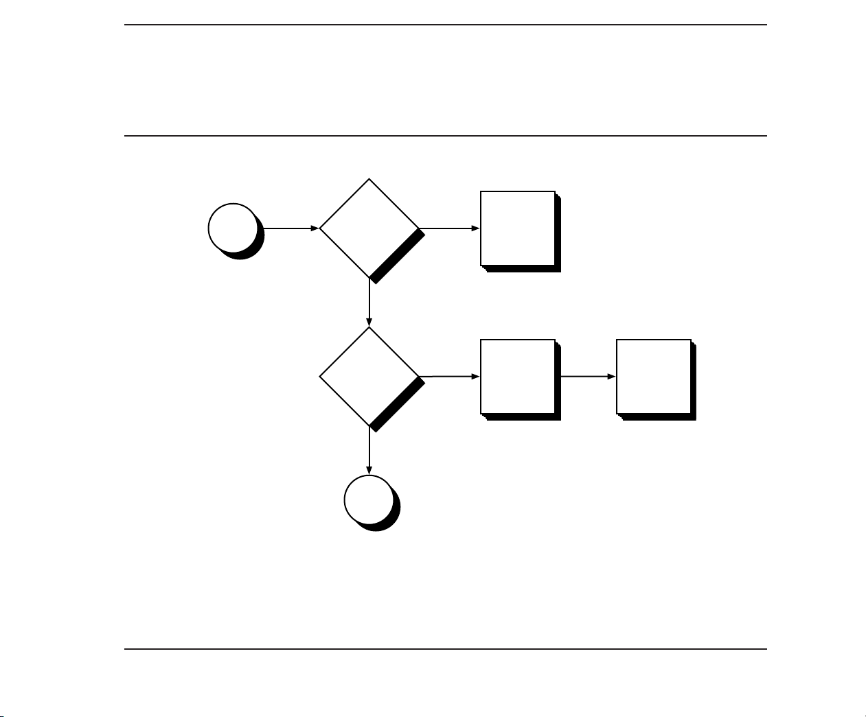
2.4 PROBLEM ISOLATION
FLOWCHART
The problem isolation flowchart provides a quick
reference for identifying and correcting possible
error conditions that may occur during POST. It
gives troubleshooting procedures for identifying
malfunctions and replacing major subassemblies
in the computer and directs you to Chapter 4,
ADVANCED DIAGNOSTICS PROGRAM, and to
Chapter 5, ERROR MESSAGES AND CODES,
for in-depth troubleshooting information.
Page 51

Maintenance and Service Guide 2-3
Complete
Preliminary
Steps.
Turn AC power
switch ON.
Did the
cursor appear
on the
monitor?
To B
Page
2-5
To A
Page
2-4
No
Yes
Page 52

2-4 Chapter 2, Power-On Self-Test
Adjust
brightness
knob
and restart.
Did the
cursor appear
on the
monitor?
To B
Page
2-5
To C
Page
2-6
No
Yes
Is the
brightness
knob turned
up?
A
No
Yes
(Post)/Problem Isolation
Page 53
Maintenance and Service Guide 2-5
See Chapter 5
ERROR
MESSAGES
AND CODES.
Did you hear
1 or 2
short beeps?
To D
Page
2-7
No
Did an
error code
appear on the
monitor?
B
Proceed with
diagnostics.
See Chapter 4
ADVANCED
DIAGNOSTICS
PROGRAM.
POST has
completed
successfully.
Yes
No
Yes
Page 54

2-6 Chapter 2, Power-On Self-Test
Is the
AC power
fuse good?
Is the
system LED
lit?
C
If replacing
the power
supply, did
not the system
LED light?
Proceed to F
Page 2-8.
Replace the
power supply
assembly and
restart.
Yes
No
Yes
POST has
completed
successfully.
No
Did the system
LED light?
No
To E
Page
2-8
To E
Page
2-8
(Post)/Problem Isolation
Page 55

Maintenance and Service Guide 2-7
Is the speaker
assembly
connected?
Did you
hear other
audible error
codes (beeps)?
D
Replace the
speaker
and restart.
See Chapter 5
ERROR
MESSAGES
AND CODES
Yes
No
Yes
Check the
speaker
assembly
connection.
No
Make proper
connection
and restart.
If beeps are
still not heard,
proceed to
Page 2-8.
Page 56

2-8 Chapter 2, Power-On Self-Test
E
E
1. Verify that all signal cables are
connected.
2. Replace the following devices in order.
3. Restart after each replacement and
check for the appearance of the cursor
and/or first screen of
the ADVANCED DIAGNOSTICS program.
□ Fuse
□ Video Display
Controller Board
□ Video Display
Monitor Unit
□ System Board
F
F
1. Verify that all signal cables are
connected.
2. Replace the following devices
in order.
□ Controller or Expansion Boards
□ Storage or Video Devices
□ System Board
(Post)/Problem Isolation
Page 57

CONTENTS
Chapter 3
SETUP PROGRAM
3.1 WHEN TO RUN SETUP 3-1
3.2 HOW TO RUN SETUP 3-2
Addendum 108431-001 (11-88) to
Manual No. 108033-003
Page 58

Page 59

Chapter 3
SETUP PROGRAM
Maintenance and Service Guide 3-1
The COMPAQ personal computer uses a memory
device that stores the current date, time, and
system configuration. The SETUP program, included on both the ADVANCED DIAGNOSTICS
and USER DIAGNOSTICS diskettes, enters this
information into the memory device.
3.1 WHEN TO RUN SETUP
You need to run SETUP:
□ When the COMPAQ personal computer is
used for the first time.
□ When the system configuration is changed.
□ When certain options are added to the
system including:
Coprocessor
Diskette drive
Fixed disk drive
Memory
Internal Modem
□ If the system board or battery is discon-
nected or replaced.
□ If a system configuration error is detected
during POST. In this situation, the system
prompts you to run SETUP so that you can
enter the correct information before
continuing.
Addendum 108431-001 (11-88) to
Manual No. 108033-003
Page 60

3-2 Chapter 3, Setup Program
3.2 HOW TO RUN SETUP
To run SETUP, follow these instructions:
1. Insert either ADVANCED DIAGNOSTICS or
USER DIAGNOSTICS diskette into drive A.
2. Turn the diskette drive latch to engage
the drive.
3. Turn on the computer and monitor. If the
computer is already on, reset the system.
The system runs POST, counting and
displaying the amount of memory and
checking the various system components.
4. Follow the instructions on the screen as
the program sets the system configuration.
NOTE: The F1 function key can be
used anytime during SETUP to
access HELP.
5. When SETUP is complete, select EXIT and
reset the system.
Addendum 108431-001 (11-88) to
Manual No. 108033-003
Page 61

CONTENTS
Chapter 4
ADVANCED DIAGNOSTICS PROGRAM
4.1 PRELIMINARY STEPS 4-1
4.2 MAIN MENU 4-2
Run the Diagnostic Tests 4-2
Format a Diskette 4-3
Run the SETUP Program 4-3
Clear Configuration and Run the SETUP Program 4-3
Display ROM Versions 4-3
4.3 ADVANCED DIAGNOSTICS PROGRAM 4-4
System Test Menu 4-4
Test Logging Utilities Menu 4-4
4.4 TEST SELECTION MENU 4-5
Processor 4-5
Memory 4-6
Keyboard 4-6
Parallel Interface 4-6
Continued...
Addendum 108431-001 (11-88) to
Manual No. 108033-003
Page 62

4.4 TEST SELECTION MENU Continued
Video 4-6
Video Controller 4-8
Display Characteristics 4-8
Character Set 4-8
80 x 25 Display 4-8
40 x 25 Display 4-9
320 x 200 Standard Graphics 4-10
640 x 200 Standard Graphics 4-10
Lightpen 4-11
Display Memory Pages 4-11
Gray Scale/Color 4-12
Noise 4-12
Enhanced Display Characteristics 4-13
640 x 200 Color Graphics 4-13
640 x 350 Color Graphics 4-14
Monochrome Text 4-15
640 x 350 Monochrome Graphics 4-15
640 x 480 Graphics 4-16
256 Color Mode 4-16
Monitor Alignment 4-17
Addendum 108431-001 (11-88) to
Manual No. 108033-003
Continued...
Page 63

4.4 TEST SELECTION MENU Continued
Diskette Drive 4-17
Write/Read/Compare 4-17
Random Seek 4-17
Verify Diskette 4-17
Diskette Speed 4-17
Diskette Change Line 4-18
Format a Diskette (for diagnostic use only) 4-18
Monochrome Video Board 4-18
Asynchronous Communications Interface 4-18
Modem 4-19
Modem Internal Loopback 4-19
Auto Originate Mode 4-19
Auto Answer Mode 4-19
Modem External Termination 4-19
Modem Direct Connect 4-20
Fixed Disk Drive 4-20
Write/Read/Compare on Test Cylinder 4-20
Seek 4-20
Head Select 4-21
Error Detection and Correction 4-21
Run All the Above Tests 4-21
Read Verify 4-21
Continued...
Addendum 108431-001 (11-88) to
Manual No. 108033-003
Page 64

4.4 TEST SELECTION MENU Continued
Fixed Disk Drive
Format Menu 4-21
Conditional Format 4-22
Unconditional Format 4-22
Surface Analysis 4-23
Change Interleave 4-23
Display Current Interleave 4-23
Fixed Disk Drive Backup (Tape) 4-24
Format Fixed Disk Drive Backup Cartridge (for diagnostic use only) 4-24
Fixed Disk Drive Backup 4-25
Fixed Disk Drive Backup Media 4-25
Enhanced Color Graphics 4-25
Video Graphics Controller 4-25
Addendum 108431-001 (11-88) to
Manual No. 108033-003
Page 65

Chapter 4
ADVANCED DIAGNOSTICS
PROGRAM
Maintenance and Service Guide 4-1
This chapter describes the ADVANCED
DIAGNOSTICS program for the COMPAQ
personal computer being tested. The screens and
information displayed are specific to the system
being tested. Diagnostics verify the proper
operation of the computer.
NOTE: When running the program, be sure to
record any messages that are displayed
during a test. This information helps in
determining defective parts or assemblies. Refer to Chapter 5, ERROR
MESSAGES AND CODES, for error
descriptions and the procedures
recommended for correcting the
error condition.
4.1 PRELIMINARY STEPS
Before running the ADVANCED DIAGNOSTICS
program, complete the following steps:
1. Turn off the computer.
2. Disconnect any peripheral devices other
than the keyboard and monitor. Do not
disconnect the printer if you want to test it
or use it to log error messages.
3. Install loopback and terminating plugs for
complete testing.
4. Insert the ADVANCED DIAGNOSTICS
diskette into drive A.
5. Turn the diskette drive latch to engage the
drive.
Addendum 108431-001 (11-88) to
Manual No. 108033-003
Page 66

4-2 Chapter 4, Advanced Diagnostics Program
6. Turn on the computer and monitor.
Once POST completes successfully, the
screen displays a list of the devices installed.
NOTE: The F1 function key can be used
anytime during SETUP to access
HELP.
7. Verify that the POST program has correctly
detected the devices installed.
□ If listed correctly, enter Y (yes) and
proceed to the main menu of ADVANCED DIAGNOSTICS.
□ If listed incorrectly, enter N (no) and
follow the instructions on the screen.
4.2 MAIN MENU
The main menu allows you to select one of the
following:
□ Run the diagnostic tests
□ Format a diskette (for diagnostic use only)
□ Run the SETUP program
□ Clear configuration and run the SETUP
program
□ Display ROM versions
These selections are described in the following
paragraphs.
Run the Diagnostic Tests
This selection presents the menu-selectable tests
and methods of testing.
Addendum 108431-001 (11-88) to
Manual No. 108033-003
Page 67

Maintenance and Service Guide 4-3
Format a Diskette
The ADVANCED DIAGNOSTICS program
requires that a diskette be formatted for each
diskette drive being tested. This utility is not
the same as the operating system FORMAT
command. A diskette formatted for diagnostics
can be used for diagnostics only, unless it is
reformatted using the operating system.
NOTE: To fully test a diskette drive, use the
highest capacity media intended for
each drive.
Run the SETUP Program
This selection runs the SETUP program to enter
all system information into the system configuration memory. For more information on the
SETUP program, refer to Chapter 3, SETUP
PROGRAM.
Clear Configuration and Run the
SETUP Program
This selection clears the system configuration
memory before invoking the SETUP program. It
may be used to return all configuration options
to the default setting. This is particularly useful
if the computer has an incorrect setting in the
configuration memory.
Display ROM Versions
This selection displays information about the
pro-cessor type and the current version level of
ROM on the system board, video display
controller, and keyboard controller.
Addendum 108431-001 (11-88) to
Manual No. 108033-003
Page 68

4-4 Chapter 4, Advanced Diagnostics Program
4.3 ADVANCED DIAGNOSTICS
PROGRAM
System Test Menu
When running the diagnostic tests, the program
allows you to:
□ Run the tests once in an interactive mode
□ Run the tests multiple times in a looping
mode
□ Select the Test Logging Utilities Menu
Test Logging Utilities Menu
This selection allows you to:
□ Log detected errors to a printer. When this
feature is turned ON, all error messages are
written to the printer.
□ Display the test log. When selected, it lists
the devices tested, the number of test passes
completed, and any errors encountered.
□ Print the test log. When the test log is
printed, it lists the devices installed and
how many test passes have been completed
on the various devices. Additionally, any
errors encountered during testing are
printed.
Addendum 108431-001 (11-88) to
Manual No. 108033-003
Page 69

Maintenance and Service Guide 4-5
4.4 TEST SELECTION MENU
The Test Selection Menu selections vary
according to the configuration of the computer
being tested. You can elect to run one test, a
combination of tests, or all of the tests. When
you run multiple tests, the program proceeds
automatically from one test to the next until
testing is completed successfully. When running
the program in the unattended mode, tests that
require operator intervention are not performed.
For complete system checkout, each test should
be run at least once in the attended mode. The
diagnostic tests are:
□ Processor
□ Memory
□ Keyboard
□ Parallel Interface
□ Video
□ Diskette Drive
□ Modem Communications
□ Fixed Disk Drive
□ Fixed Disk Drive Backup (Tape)
□ Enhanced Color Graphics or Video Graphics
□ Auxiliary Input Interface
NOTE: If error codes appear as you run the
tests, refer to Chapter 5, ERROR MES-
SAGES AND CODES, for a list of error
codes, code descriptions, and the procedures recommended for correcting the
error condition.
The following paragraphs describe these tests.
Processor
The Processor test verifies the main processor,
coprocessor (if installed), configuration (CMOS)
memory (if applicable), processor support logic,
and speaker.
□ Monochrome Video Board
□ Asynchronous Communications Interface
Addendum 108431-001 (11-88) to
Manual No. 108033-003
Page 70

4-6 Chapter 4, Advanced Diagnostics Program
Memory
The Memory test verifies memory data patterns,
memory addressing, and parity detection for all
system memory.
Keyboard
The Keyboard test verifies the keyboard interface, the individual keys, the LED indicators, the
repeat action key mode, and the security lock
(if applicable).
Parallel Interface
The Parallel Interface test verifies interface data
and control lines, internal loopback control
circuitry, external loopback (if a loopback plug
is attached), and a shifted pattern of standard
printable characters (if a printer is connected).
NOTE: Before selecting this test, be sure you
know which device is set to LPT1 or
LPT2. This is necessary to determine
the applicability of any messages or
error codes that may appear. For more
complete testing of the parallel interface,
attach a loopback plug.
Video
Depending on the devices installed in the
computer being tested, you can run selected
tests or all of the tests listed in Table 4-1. It
details the possible tests for various system video
configurations and indicates the screens that
appear during the tests (assuming only one
video controller is installed).
NOTE: The screens that appear in this section
are provided for reference only and may
vary depending on the type of video
controller or monitor being used.
Addendum 108431-001 (11-88) to
Manual No. 108033-003
Page 71

Maintenance and Service Guide 4-7
Table 4-1. Matrix of Possible Video Tests
Video Controller/Display
EGA
Video Test CGA
Video Controller X X X X X X
Display Characteristics X X X X X
Character Set X X X X X
80 x 25 Display X X X X X
40 x 25 Display X X X X X
320 x 200 Standard Graphics X X X X X
640 x 200 Standard Graphics X X X X
Lightpen X X X
Display Memory Pages X X X X X X
Gray Scale/Color X X X X
Noise X X X X X X
Enhanced Display Characteristics X X
640 x 200 Color Graphics X X X
640 x 350 Color Graphics X X X
Monochrome Text X X X
640 x 350 Monochrome Graphics X X
640 x 480 Graphics X
256 Color Mode X
Monitor Alignment X X X
CGA - Color graphics adapter
DMM - Dual-mode monitor
EGA - Enhanced graphics adapter
MDA - Monochrome display adapter
VGA - Video graphics array
W/DMM
EGA
W/COLOR
VGA
W/COLOR
VGA
W/MONO MDA
Addendum 108431-001 (11-88) to
Manual No. 108033-003
Page 72

4-8 Chapter 4, Advanced Diagnostics Program
The following paragraphs describe the tests for
the various video configurations.
Video Controller
The Video Controller selection verifies the
integrity of the video display controller, the
video graphics controller, or the enhanced color
graphics board.
Display Characteristics
The Display Characteristics selection verifies the
ability of the video display controller and monitor to display certain attributes: various intensities, blinking, and reverse video.
Character Set
The Character Set selection verifies that the
system can display all of the available character
patterns.
80 x 25 Display
The 80 x 25 Display selection verifies that the
system can operate in both the high-resolution
and low-resolution modes.
The screen for the 80 x 25 high-resolution text
mode (9 x 14 character matrix) using inverted
video appears similar to Screen 1.
Addendum 108431-001 (11-88) to
Manual No. 108033-003
Screen 1.
Page 73
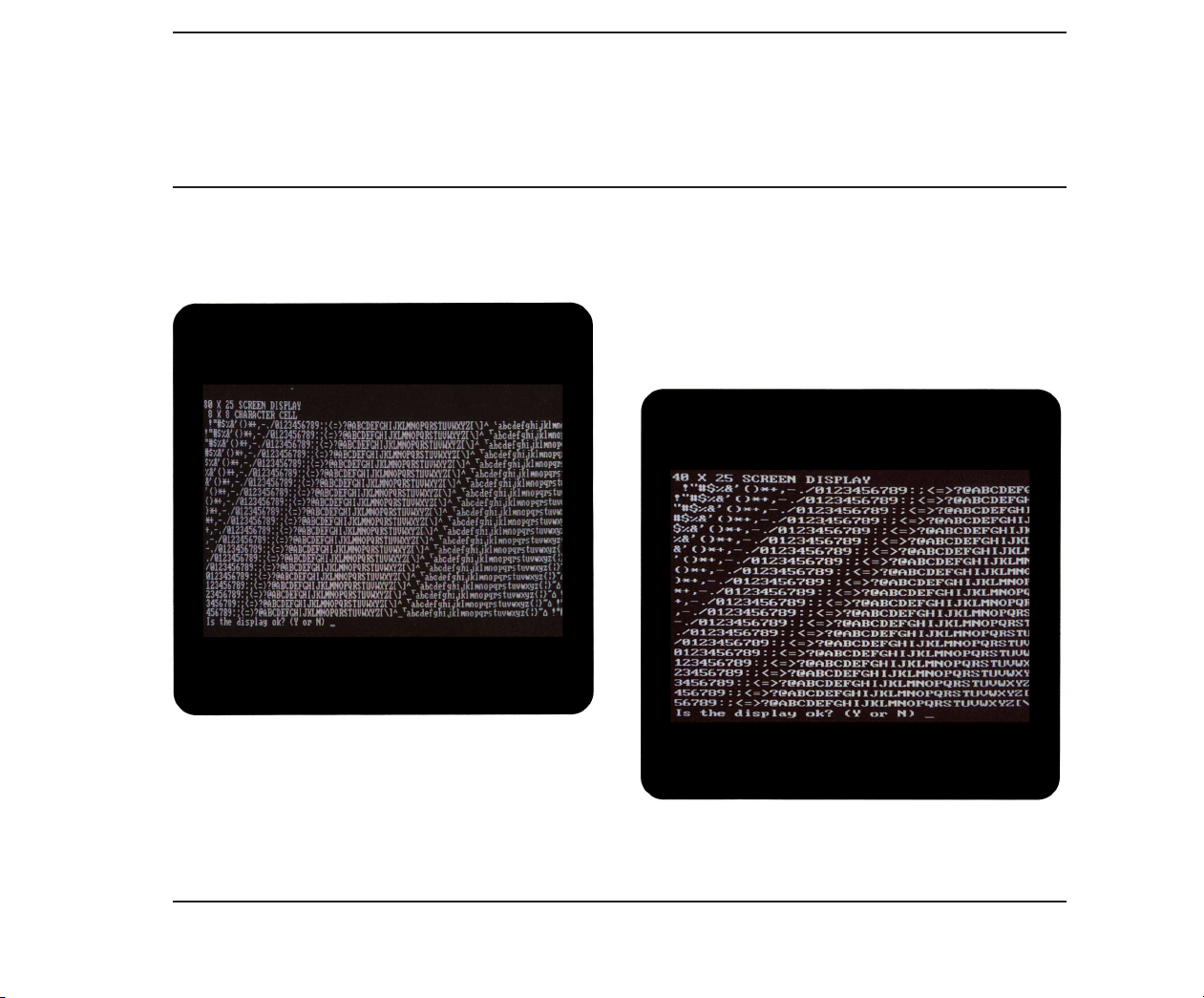
Maintenance and Service Guide 4-9
The screen for the 80 x 25 low-resolution character display mode (8 x 8 character matrix) appears
similar to Screen 2.
Screen 2.
40 x 25 Display
The 40 x 25 Display selection verifies that the
system can operate in the 40 x 25 low-resolution
character display mode 8 x 8 character matrix).
A display similar to Screen 3 appears on
the monitor.
Screen 3.
Addendum 108431-001 (11-88) to
Manual No. 108033-003
Page 74

4-10 Chapter 4, Advanced Diagnostics Program
320 x 200 Standard Graphics
The 320 x 200 Standard Graphics selection
verifies that the system can operate in the
320 x 200 color graphics mode with color sets
0 and 1. A display similar to Screen 4 appears
for the color sets.
640 x 200 Standard Graphics
The 640 x 200 Standard Graphics selection
verifies that the system can operate in the
640 x 200 monochrome graphics mode. A
display similar to Screen 5 appears.
Screen 4.
Addendum 108431-001 (11-88) to
Manual No. 108033-003
Screen 5.
Page 75

Lightpen
The Lightpen selection verifies that the lightpen
is operating properly with the color monitor.
Display Memory Pages
The Display Memory Pages selection verifies
that the system can address all eight pages
(0 through 7) of the memory on the video display
controller. A display similar to Screen 6 appears
for the eighth page.
Maintenance and Service Guide 4-11
Screen 6.
Addendum 108431-001 (11-88) to
Manual No. 108033-003
Page 76

4-12 Chapter 4, Advanced Diagnostics Program
Gray Scale/Color
The Gray Scale/Color selection verifies that the
system can display as many as 16 shades of the
gray scale and all 8 possible colors (at 2 intensities for each). A display similar to Screen 7
appears on the monitor.
Noise
The Noise selection checks the amount of electronic noise generated from the video controller;
it also tests the ability of the controller to
communicate with the system board.
Addendum 108431-001 (11-88) to
Manual No. 108033-003
Screen 7.
Page 77

Maintenance and Service Guide 4-13
Enhanced Display Characteristics
The Enhanced Display Characteristics selection
verifies the ability of the video display controller
and monitor to display certain attributes: normal
and high intensities; blinking; inverted video;
and shades of red, blue, green, and gray. A display similar to Screen 8 appears on the monitor.
640 x 200 Color Graphics
The 640 x 200 Color Graphics selection verifies
that the system can operate in the 640 x 200
color graphics mode, displaying 16 different
colors. A display similar to Screen 9 appears on
the monitor.
Screen 8.
Screen 9.
Addendum 108431-001 (11-88) to
Manual No. 108033-003
Page 78

4-14 Chapter 4, Advanced Diagnostics Program
640 x 350 Color Graphics
The 640 x 350 Color Graphics selection verifies
that the system can operate in the 640 x 350
color graphics mode by displaying the first 16 of
64 possible colors, then all 64 possible colors.
Displays of the first 16 colors appear similar to
Screen 10.
Displays of all 64 possible colors appear similar
to Screen 11.
Screen 11.
Screen 10.
Addendum 108431-001 (11-88) to
Manual No. 108033-003
Page 79

Maintenance and Service Guide 4-15
Monochrome Text
The Monochrome Text selection verifies that
the system can operate in the monochrome text
mode. A display similar to Screen 12 appears on
the monitor with the word “monochrome”
blinking.
640 x 350 Monochrome Graphics
The 640 x 350 Monochrome Graphics selection
verifies that the system can operate in the
640 x 350 monochrome graphics mode. A display
similar to Screen 13 appears on the monitor
with the word “monochrome” blinking.
Screen 12.
Screen 13.
Addendum 108431-001 (11-88) to
Manual No. 108033-003
Page 80

4-16 Chapter 4, Advanced Diagnostics Program
640 x 480 Graphics
The 640 x 480 Graphics selection verifies that
the system can operate in the 640 x 480 graphics
mode. A display similar to Screen 14 appears on
the monitor.
256 Color Mode
The 256 Color Mode selection verifies the different shading of nine colors. A display similar to
Screen 15 appears on the monitor.
Screen 14.
Addendum 108431-001 (11-88) to
Manual No. 108033-003
Screen 15.
Page 81

Maintenance and Service Guide 4-17
Monitor Alignment
The Monitor Alignment selection allows you to
check the alignment and intensity of the video
display unit.
Diskette Drive
The Diskette Drive test verifies that the diskette
drive, diskette drive controller, and associated
cables are operating properly.
The following selections are available:
□ Write/Read/Compare
□ Random Seek
□ Verify Diskette
□ Diskette Speed
□ Diskette Change Line
□ Format a Diskette (for diagnostic use only)
NOTE: During certain tests, you may be asked
to insert a blank diskette that has been
formatted for diagnostics. To fully test
a diskette drive, use the highest capacity media intended for the drive. The
diskette must not be write protected.
The following paragraphs describe these selections.
Write/Read/Compare
The Write/Read/Compare selection verifies that
the diskette drive subsystem writes, reads, and
compares data patterns, that the diskette drive
controller properly resets, and that the diskette
drive controller buffers are valid.
Random Seek
The Random Seek selection verifies that the
diskette drive and the diskette drive controller
randomly seek tracks across the diskette.
Verify Diskette
The Verify Diskette selection verifies the diskette drive by reading the contents of the entire
diskette.
Diskette Speed
The Diskette Speed selection verifies that the diskette drive motor is spinning within the proper
speed range.
Addendum 108431-001 (11-88) to
Manual No. 108033-003
Page 82

4-18 Chapter 4, Advanced Diagnostics Program
Diskette Change Line
The Diskette Change Line selection verifies
that the diskette drive change-line circuitry is
functioning properly. You may be instructed to
remove and reinsert the blank diskette that has
been formatted for diagnostics.
Format a Diskette (for diagnostic use only)
The ADVANCED DIAGNOSTICS program
requires that a diskette be formatted for each
diskette drive being tested. This utility is not
the same as the operating system FORMAT
command. A diskette formatted for diagnostics
can be used for diagnostics only, unless it is
reformatted using the operating system.
NOTE: To fully test a diskette drive, use the
highest capacity media intended for
the drive.
Monochrome Video Board
For a description of this test, see “Video Tests”
described previously.
Asynchronous Communications
Interface
The Asynchronous Communications Interface
test verifies interface data and control lines,
baud rate, internal loopback control circuitry,
external loopback circuitry (if a loopback plug is
attached), as well as clock and calendar functions
(if applicable).
NOTE: This selection tests all asynchronous
communications interfaces. Before
selecting this test, be sure you know
which device is set to COM1 and which is
set to COM2. This is necessary to determine the applicability of any messages or
error codes that may appear. For more
complete testing of an asynchronous
communications interface, attach a
loopback plug.
Addendum 108431-001 (11-88) to
Manual No. 108033-003
Page 83

Maintenance and Service Guide 4-19
Modem
The Modem test runs a series of other tests that
verify the modem and interface cables.
The following selections are available:
□ Modem Internal Loopback
□ Auto Originate Mode
□ Auto Answer Mode
□ Modem External Termination
□ Modem Direct Connect
The following paragraphs describe these selections.
Modem Internal Loopback
The Modem Internal Loopback selection verifies
the TIP/RING (two wire) loopback circuitry
as well as the data transfer and bit error
rate circuitry.
Auto Originate Mode
The Auto Originate Mode selection verifies
that the modem subassembly can dial a remote
modem, establish the transmission line carrier,
check the transmission line quality, perform data
transfer, check bit error rate, and disconnect the
transmission carrier.
Auto Answer Mode
The Auto Answer Mode selection verifies that the
modem subassembly can receive an incoming
dial-up call, establish the transmission line
carrier, check the transmission line quality,
perform data transfer, check bit error rate, and
disconnect the transmission carrier.
Modem External Termination
The Modem External Termination selection
verifies that the TIP/RING (two wire) lines are
externally available.
NOTE: Before running this test, attach a modem
terminating plug.
Addendum 108431-001 (11-88) to
Manual No. 108033-003
Page 84

4-20 Chapter 4, Advanced Diagnostics Program
Modem Direct Connect
The Modem Direct Connect selection verifies the
TIP/RING (two wire) loopback circuitry as well
as the data transfer and bit error rate circuitry
(as does the Modem Internal Loopback selection, above). It also verifies that the modem can
communicate with another modem. This test
is performed when two modems in different
computers are directly connected through one
telephone cable. The selection does not verify
dialing, originating, or answering.
Fixed Disk Drive
The Fixed Disk Drive test runs a series of tests
that verify the fixed disk drive, the fixed disk
drive controller, and cables. Depending on the
computer configuration, a Fixed Disk Drive
Menu may appear. The selections allow you to
run any one or all of the tests on any physical
drive.
The following selections are available:
□ Error Detection and Correction
□ Run All the Above Tests
□ Read Verify
□ Format Menu
The following paragraphs describe these selections.
Write/Read/Compare on Test Cylinder
The Write/Read/Compare on Test Cylinder
selection writes information from memory to the
fixed disk drive on the test cylinder, reads it back,
then compares it to what is in memory.
Seek
The Seek selection performs a sequential seek
over the fixed disk drive then performs a random
seek to verify the ability of the head actuator to
find randomly selected cylinders in a predetermined amount of time.
□ Write/Read/Compare on Test Cylinder
□ Seek
□ Head Select
Addendum 108431-001 (11-88) to
Manual No. 108033-003
Page 85

Maintenance and Service Guide 4-21
Head Select
The Head Select selection verifies that each head
of the fixed disk drive can be accessed and is
functional.
Error Detection and Correction
The Error Detection and Correction selection
verifies that the error detection circuitry in the
fixed disk drive can properly calculate the error
correction code.
Run All the Above Tests
The Run All the Above Tests selection allows all
of the previously described Fixed Disk Drive Test
selections to run sequentially.
Read Verify
The Read Verify selection verifies that the system
can read each track of the fixed disk drive. The
program reads the entire disk and reports the
number of unusable tracks, if any.
Format Menu
The Format Menu selection provides two format
program options and two formatting features for
special applications only. The Format Menu
allows you to run the following tests selectively
on each physical drive present.
CAUTION
The fixed disk drive format selection
destroys all data on the fixed disk drive.
Before Formatting, back up all data stored
on the fixed disk drive.
The Format Menu selections available are:
□ Conditional Format
□ Unconditional Format
□ Surface Analysis
□ Change Interleave
□ Display Current Interleave
Addendum 108431-001 (11-88) to
Manual No. 108033-003
Page 86

4-22 Chapter 4, Advanced Diagnostics Program
IMPORTANT
Because several of these selections destroy
all information on the fixed disk drive, you
may need to reinitialize the fixed disk drive.
For more information on initializing the
fixed disk drive, refer to operating system
documentation.
The following paragraphs describe the Format
Menu selections.
Conditional Format
The Conditional Format selection reads the disk
to find tracks formatted as unusable, reformats
the entire disk, and then restores the original
unusable track information. It then performs a
complete surface analysis to find other unusable
tracks.
NOTE: The computer must be turned on for at
least 20 minutes before formatting the
fixed disk drive.
Also, it is very important that this test
be allowed to run to completion once
started. If the test does not run to
completion, bad-track information may
be lost.
When the Conditional Format completes without
error, repeat the Fixed Disk Drive test to verify
that the fixed disk drive and the fixed disk drive
controller (if applicable) are functioning properly.
Unconditional Format
The Unconditional Format selection formats all
tracks as good, except for those entered by the
user. This test accepts a list of usable tracks from
the user, reformats the entire disk, and then
reformats as unusable the tracks entered by the
user. Additionally, you may elect to run a Surface
Analysis automatically after the Unconditional
Format.
Addendum 108431-001 (11-88) to
Manual No. 108033-003
Page 87

Maintenance and Service Guide 4-23
NOTE: An Unconditional Format should be
performed only if you are sure that
tracks marked bad on the fixed disk drive
are not actually bad. Good tracks may be
marked bad as a result of using a
defective fixed disk drive controller or
controller cable.
You must perform a Surface Analysis
after an Unconditional Format to identify
any additional bad tracks that may exist
on the fixed disk drive.
Run the Fixed Disk Drive test to verify that the
fixed disk drive and the fixed disk drive controller (if applicable) are functioning properly.
Surface Analysis
The Surface Analysis selection performs multiple
write/read/compares on each track of the disk in
search of more unusable tracks. It formats tracks
to be unusable when errors are found.
Change Interleave
The Change Interleave selection permits you
to change the interleave factor of the fixed disk
drive. You must run either the Conditional or
Unconditional Format to enable the new interleave factor.
CAUTION
Changing the interleave factor can drastically
reduce the performance of the system. The
interleave factor is preset to achieve maximum efficiency from the computer.
Do not choose this selection unless you are
required to do so, either by a software program or by an operating system other than
MS-DOS. Changing the interleave factor
requires that the drive be reformatted to
function properly.
Display Current Interleave
The Display Current Interleave selection tests
the fixed disk drive and reports the current interleave setting.
Addendum 108431-001 (11-88) to
Manual No. 108033-003
Page 88

4-24 Chapter 4, Advanced Diagnostics Program
Fixed Disk Drive Backup (Tape)
The Fixed Disk Drive Backup (Tape) test verifies
the tape backup, the fixed disk drive controller, the tape host adapter, and associated cables.
Depending on the computer configuration, the
Fixed Disk Drive Backup Menu may appear.
This menu allows you to run the following tests
selectively:
□ Format Fixed Disk Drive Backup Cartridge
(for diagnostic use only)
□ Fixed Disk Drive Backup Device
□ Fixed Disk Drive Backup Media
During each of these tests, the screen displays
each track and block as it is checked. The following paragraphs describe these selections.
Format Fixed Disk Drive Backup Cartridge
(for diagnostic use only)
This selection formats a fixed disk drive backup
tape cartridge for use during diagnostic testing.
This selection tests the format and servo write
circuitry.
CAUTION
This test will destroy stored data. When
prompted, be sure to insert a blank tape
cartridge to avoid losing data.
The test goes through two stages of formatting:
physical formatting and logical formatting. Each
stage requires an extended period of time.
CAUTION
Do not interrupt the physical formatting
process in any way. An interruption can
destroy the servo information on the tape
cartridge requiring erasure before reformatting.
Addendum 108431-001 (11-88) to
Manual No. 108033-003
Page 89

Maintenance and Service Guide 4-25
Fixed Disk Drive Backup
The Fixed Disk Drive Backup selection verifies
that the system can identify the following on
selected tracks of the tape cartridge: drive type;
cartridge in place; write protect, beginning of
tape (BOT), and end of tape (EOT) sensors; drive
motion and seek circuitry; drive indexing circuitry; and drive write and read circuitry.
Fixed Disk Drive Backup Media
The Fixed Disk Drive Backup Media selection
verifies that the system can rewind the tape
cartridge to the beginning of the tape (BOT) and
the end of the tape (EOT) as well as write, read,
and compare data to all blocks and tracks of the
cartridge.
Enhanced Color Graphics
For a description of this test, see “Video Tests”
described previously.
Video Graphics Controller
For a description of this test, see “Video Tests”
described previously.
Addendum 108431-001 (11-88) to
Manual No. 108033-003
Page 90

Page 91

CONTENTS
Chapter 5
ERROR MESSAGES AND CODES
5.1 INTRODUCTION 5-1
5.2 POWER-ON SELF-TEST ERROR MESSAGES 5-1
5.3 ADVANCED DIAGNOSTICS ERROR CODES 5-4
5.4 MEMORY ERROR CODES 5-31
5.5 EXTDISK MESSAGES 5-36
Page 92

Page 93

Maintenance and Service Guide 5-1
[ page missing ]
Addendum 108431-001 (11-88) to
Manual No. 108033-003
Page 94

5-2 Chapter 5, Error Messages and Codes
[ page missing ]
Addendum 108431-001 (11-88) to
Manual No. 108033-003
Page 95

Maintenance and Service Guide 5-3
Table 5-1. Power-On Self-Test Error Messages Continued
Message Beeps Probable Cause Recommended Action
402–Monochrome
Adapter Failure
501–Display Adapter
Failure
601–Diskette Controller
Error
605–Diskette Drive
Type Error
702–Coprocessor
Detection Error
1780–Disk 0 Failure None Fixed disk drive/format error Run ADVANCED DIAGNOSTICS.
1781–Disk 1 Failure None Fixed disk drive/format error Run ADVANCED DIAGNOSTICS.
1782–Disk Controller
Failure
1790–Disk 0 Error None Fixed disk drive recalibration
1791–Disk 1 Error None Fixed disk drive recalibration
Parity Check 2 XX000Y ZZ None Parity RAM failure Run ADVANCED DIAGNOSTICS.
Audible 1S
Audible 2S
(RESUME = “F1” KEY) None As indicated Press F1 key to continue.
1
L = Long
2
S = Short
1L1, 2S2 Monochrome display
controller board
2
1L1, 2S
Video display controller
board
None Multipurpose fixed disk
drive controller board
Mismatch in drive type Run Setup.
None Coprocessor or switch
setting problem
None Fixed disk drive controller
error
or wrong drive type
or wrong drive type
2
2
Power-on successful None.
Power-on successful None.
Replace the monochrome display controller board.
Replace the video board.
Replace the multipurpose fixed disk
drive controller board.
1. Check the switch settings.
2. Replace the coprocessor.
Run ADVANCED DIAGNOSTICS.
Run SETUP and ADVANCED
DIAGNOSTICS.
Run SETUP and ADVANCED
DIAGNOSTICS.
Addendum 108431-001 (11-88) to
Manual No. 108033-003
Page 96

5-4 Chapter 5, Error Messages and Codes
5.3 ADVANCED DIAGNOSTICS
ERROR CODES
ADVANCED DIAGNOSTICS error codes occur if
the system recognizes a problem while running
the COMPAQ ADVANCED DIAGNOSTICS Program. These error codes help identify possible
defective subassemblies.
Table 5-2 lists possible error codes, a description
of the error condition, and the action required to
resolve the error condition.
In each case, the Recommended Action column
lists steps necessary to correct the problem. After
completing each step, run the ADVANCED
DIAGNOSTICS Program to verify whether the
error condition has been corrected. If the error
code reappears, perform the next step, then run
the ADVANCED DIAGNOSTICS Program.
Follow this procedure until the ADVANCED
DIAGNOSTICS Program no longer detects an
error condition.
The error codes are in the form of AYY-XX or
AAYY-XX. A or AA is the number that represents
the faulty subassembly. YY denotes the test or
action that failed. XX denotes a specific problem. For example, error code 610-01 shows that
the diskette drive change line test exceeded the
maximum soft error limit.
For assistance in the removal and replacement
of a particular subassembly, see Chapter 7,
REMOVAL AND REPLACEMENT
PROCEDURES.
Addendum 108431-001 (11-88) to
Manual No. 108033-003
Page 97

Maintenance and Service Guide 5-5
[ page missing ]
Addendum 108431-001 (11-88) to
Manual No. 108033-003
Page 98

5-6 Chapter 5, Error Messages and Codes
[ page missing ]
Addendum 108431-001 (11-88) to
Manual No. 108033-003
Page 99

Maintenance and Service Guide 5-7
Table 5-2. Advanced Diagnostics Error Codes Continued
Error
Code Description
105-07 Port 61 bit 3 not at one. Replace the system board and retest for error codes
105-08 Port 61 bit 1 not at one.
105-09 Port 61 bit 0 not at one.
105-10 Port 61 I/O test failed.
105-11 Port 61 bit 7 not at zero.
105-12 Port 61 bit 2 not at zero.
105-13 No interrupt generated by
failsafe timer.
105-14 NMI not triggered by failsafe timer.
106-01 Keyboard controller self-test failed.
107-01 CMOS RAM test failed.
108-02 CMOS interrupt test failed.
108-03 CMOS interrupt test, CMOS not
properly initialized.
109-01 CMOS clock load data test failed.
109-02 CMOS clock rollover test failed.
109-03 CMOS clock test, CMOS not
properly initialized.
110-01 Programmable timer load data
test failed.
110-02 Programmable timer dynamic
test failed.
110-03 Programmable timer #2 load data
test failed.
Recommended
Action
103-xx through 113-xx.
Continued...
Addendum 108431-001 (11-88) to
Manual No. 108033-003
Page 100

5-8 Chapter 5, Error Messages and Codes
Table 5-2. Advanced Diagnostics Error Codes Continued
Error
Code Description
111-01 Refresh detect test failed. Replace the system board and retest for error codes
112-01 Speed test slow mode out of range.
112-02 Speed test mixed mode out of range.
112-03 Speed test fast mode out of range.
112-04 Speed test unable to enter slow mode.
112-05 Speed test unable to enter mixed mode.
112-06 Speed test unable to enter fast mode.
112-07 Speed test system error.
112-08 Speed test unable to enter auto mode.
112-09 Speed test unable to enter high mode.
112-10 Speed test high mode out of range.
112-11 Speed test auto mode out of range.
112-12 Speed test variable speed mode
inoperative.
113-01 Protected mode test failed.
114-01 Speaker test failed. 1. Verify the speaker connection.
199-00 Installed devices test failed. 1. Check system configuration.
Recommended
Action
103-xx through 113-xx.
2. Replace the speaker and retest.
3. Replace the system board and retest.
2. Verify cable connection.
3. Check switch settings.
4. Run SETUP.
5. Replace the system board and retest.
Continued...
Addendum 108431-001 (11-88) to
Manual No. 108033-003
 Loading...