

Page 1

b
Hardware and Software
Guide
Compaq Notebook Series
Document Part Number: 383161-001
May 2005
This guide explains how to identify, access, and use most of
hardware and software features available on your notebook.
the
Modem information is not included in this guide.
Page 2

© Copyright 2005 Hewlett-Packard Development Company, L.P.
Microsoft and Windows are U.S. registered trademarks of Microsoft
Corporation. SD Logo is a trademark of its proprietor. Bluetooth is a
trademark owned by its proprietor and used by Hewlett-Packard Company
under license.
The information contained herein is subject to change without notice. The
only warranties for HP products and services are set forth in the express
warranty statements accompanying such products and services. Nothing
herein should be construed as constituting an additional warranty. HP shall
not be liable for technical or editorial errors or omissions contained herein.
Hardware and Software Guide
Compaq Notebook Series
First Edition May 2005
Reference Number: V2000
Document Part Number: 383161-001
Page 3

Contents
1 Component ID
Top Components . . . . . . . . . . . . . . . . . . . . . . . . . . . . . . . 1–1
Keys. . . . . . . . . . . . . . . . . . . . . . . . . . . . . . . . . . . . . . 1–1
TouchPad . . . . . . . . . . . . . . . . . . . . . . . . . . . . . . . . . . 1–3
Power Controls . . . . . . . . . . . . . . . . . . . . . . . . . . . . . 1–4
Lights. . . . . . . . . . . . . . . . . . . . . . . . . . . . . . . . . . . . . 1–5
Wireless and Volume Buttons . . . . . . . . . . . . . . . . . . 1–6
Antennae . . . . . . . . . . . . . . . . . . . . . . . . . . . . . . . . . . 1–7
Front Components . . . . . . . . . . . . . . . . . . . . . . . . . . . . . . 1–8
Lights. . . . . . . . . . . . . . . . . . . . . . . . . . . . . . . . . . . . . 1–8
Speakers, Jacks and Display Release Button. . . . . . . 1–9
Rear Components. . . . . . . . . . . . . . . . . . . . . . . . . . . . . . 1–10
Left-Side Components . . . . . . . . . . . . . . . . . . . . . . . . . . 1–11
Ports and Jacks. . . . . . . . . . . . . . . . . . . . . . . . . . . . . 1–11
PC Card Slot and Button . . . . . . . . . . . . . . . . . . . . . 1–12
Vent and Security Cable Slot. . . . . . . . . . . . . . . . . . 1–13
Right-Side Components . . . . . . . . . . . . . . . . . . . . . . . . . 1–14
Bottom Components. . . . . . . . . . . . . . . . . . . . . . . . . . . . 1–16
Mini PCI and Memory Compartments . . . . . . . . . . 1–16
Bays, Battery Latch and Vents . . . . . . . . . . . . . . . . 1–17
Additional Components . . . . . . . . . . . . . . . . . . . . . . . . . 1–18
Hardware . . . . . . . . . . . . . . . . . . . . . . . . . . . . . . . . . 1–18
Optical Discs . . . . . . . . . . . . . . . . . . . . . . . . . . . . . . 1–19
Labels. . . . . . . . . . . . . . . . . . . . . . . . . . . . . . . . . . . . 1–19
Hardware and Software Guide iii
Page 4

Contents
2 Keyboard and Touchpad
TouchPad . . . . . . . . . . . . . . . . . . . . . . . . . . . . . . . . . . . . . 2–1
Identifying TouchPad Components. . . . . . . . . . . . . . 2–1
Using the TouchPad. . . . . . . . . . . . . . . . . . . . . . . . . . 2–2
Setting TouchPad Preferences . . . . . . . . . . . . . . . . . . 2–3
Hotkeys . . . . . . . . . . . . . . . . . . . . . . . . . . . . . . . . . . . . . . 2–5
Identifying Hotkeys . . . . . . . . . . . . . . . . . . . . . . . . . . 2–5
Hotkey Quick Reference . . . . . . . . . . . . . . . . . . . . . . 2–6
Using Hotkey Procedures . . . . . . . . . . . . . . . . . . . . . 2–7
Using Hotkey Commands . . . . . . . . . . . . . . . . . . . . . 2–7
Keypads . . . . . . . . . . . . . . . . . . . . . . . . . . . . . . . . . . . . . 2–14
Using the Embedded Numeric Keypad . . . . . . . . . . 2–14
Using an External Numeric Keypad . . . . . . . . . . . . 2–16
3Power
Power Sources . . . . . . . . . . . . . . . . . . . . . . . . . . . . . . . . . 3–1
Selecting a Power Source . . . . . . . . . . . . . . . . . . . . . 3–1
Switching Between Battery and External Power. . . . 3–2
Power Control and Light Locations . . . . . . . . . . . . . . . . . 3–3
Standby, Hibernation and Shutdown Overviews . . . . . . . 3–4
Standby . . . . . . . . . . . . . . . . . . . . . . . . . . . . . . . . . . . 3–4
Hibernation . . . . . . . . . . . . . . . . . . . . . . . . . . . . . . . . 3–5
Leaving Your Work. . . . . . . . . . . . . . . . . . . . . . . . . . 3–6
Interference with Drive Media . . . . . . . . . . . . . . . . . 3–6
Standby, Hibernation and Shutdown Procedures. . . . . . . 3–7
Turning the Notebook On or Off. . . . . . . . . . . . . . . . 3–7
Initiating or Resuming from Standby . . . . . . . . . . . . 3–8
Initiating or Restoring from Hibernation. . . . . . . . . . 3–9
Using Emergency Shutdown Procedures . . . . . . . . 3–10
Power Preferences . . . . . . . . . . . . . . . . . . . . . . . . . . . . . 3–11
Using Power Schemes . . . . . . . . . . . . . . . . . . . . . . . 3–11
Setting a Standby Password. . . . . . . . . . . . . . . . . . . 3–11
Setting Other Power Preferences. . . . . . . . . . . . . . . 3–11
iv Hardware and Software Guide
Page 5

Battery Pack . . . . . . . . . . . . . . . . . . . . . . . . . . . . . . . . . . 3–13
Charging a Battery Pack . . . . . . . . . . . . . . . . . . . . . 3–13
Monitoring the Charge in a Battery Pack . . . . . . . . 3–15
Managing Low-Battery Conditions. . . . . . . . . . . . . 3–17
Calibrating a Battery Pack. . . . . . . . . . . . . . . . . . . . 3–19
Conserving Battery Pack Power . . . . . . . . . . . . . . . 3–23
Replacing a Battery Pack. . . . . . . . . . . . . . . . . . . . . 3–24
Storing a Battery Pack . . . . . . . . . . . . . . . . . . . . . . . 3–27
Disposing of a Used Battery Pack . . . . . . . . . . . . . . . . . 3–28
4 Multimedia
Internal Speakers . . . . . . . . . . . . . . . . . . . . . . . . . . . . . . . 4–1
Volume Controls . . . . . . . . . . . . . . . . . . . . . . . . . . . . . . . 4–2
External Audio Devices . . . . . . . . . . . . . . . . . . . . . . . . . . 4–3
Using the Audio-Out (Headphone) Jack . . . . . . . . . . 4–3
Using the Audio-In (Microphone) Jack. . . . . . . . . . . 4–4
External Video Devices . . . . . . . . . . . . . . . . . . . . . . . . . . 4–5
Connecting an S-Video Device . . . . . . . . . . . . . . . . . 4–5
Displaying a Video Image . . . . . . . . . . . . . . . . . . . . . 4–6
CD and DVD Procedures . . . . . . . . . . . . . . . . . . . . . . . . . 4–7
Using Media Activity Hotkeys . . . . . . . . . . . . . . . . . 4–7
Protecting Playback . . . . . . . . . . . . . . . . . . . . . . . . . . 4–8
Protecting a CD or DVD Write Process . . . . . . . . . . 4–8
Multimedia Software . . . . . . . . . . . . . . . . . . . . . . . . . . . . 4–9
Observing the Copyright Warning . . . . . . . . . . . . . 4–10
Installing Software. . . . . . . . . . . . . . . . . . . . . . . . . . 4–11
Enabling AutoPlay. . . . . . . . . . . . . . . . . . . . . . . . . . 4–12
Changing DVD Region Settings . . . . . . . . . . . . . . . 4–12
Using the Operating System . . . . . . . . . . . . . . . . . . 4–13
Using WinDVD . . . . . . . . . . . . . . . . . . . . . . . . . . . . 4–14
Using Other DVD Software . . . . . . . . . . . . . . . . . . 4–14
Contents
Hardware and Software Guide v
Page 6

Contents
5 Wireless
(Select Models Only)
Wireless Features . . . . . . . . . . . . . . . . . . . . . . . . . . . . . . . 5–1
Wireless Controls. . . . . . . . . . . . . . . . . . . . . . . . . . . . . . . 5–2
802.11 Wireless Devices (Select Models Only) . . . . . . . 5–3
Setting Up a WLAN in Your Home . . . . . . . . . . . . . 5–5
Connecting to a WLAN in Your Home. . . . . . . . . . . 5–6
Connecting to a Public WLAN . . . . . . . . . . . . . . . . . 5–7
Using Wireless Security Features . . . . . . . . . . . . . . . 5–7
Identifying an 802.11 Wireless Device . . . . . . . . . . . 5–8
Troubleshooting Devices. . . . . . . . . . . . . . . . . . . . . . 5–8
Bluetooth Wireless Devices (Select Models Only) . . . . . 5–9
Wireless Device Power States . . . . . . . . . . . . . . . . . . . . 5–11
Turning On the Devices. . . . . . . . . . . . . . . . . . . . . . 5–13
Turning Off and Disabling the Devices. . . . . . . . . . 5–14
6 Security
Security Features . . . . . . . . . . . . . . . . . . . . . . . . . . . . . . . 6–1
QuickLock . . . . . . . . . . . . . . . . . . . . . . . . . . . . . . . . . . . . 6–3
Setup Utility and Windows Passwords . . . . . . . . . . . . . . 6–4
Coordinating Passwords . . . . . . . . . . . . . . . . . . . . . . 6–6
Choosing a Password. . . . . . . . . . . . . . . . . . . . . . . . . 6–6
Setup Utility Administrator Password . . . . . . . . . . . . . . . 6–7
Setting an Administrator Password . . . . . . . . . . . . . . 6–8
Entering an Administrator Password. . . . . . . . . . . . . 6–8
Setup Utility Power-On Password . . . . . . . . . . . . . . . . . . 6–9
Setting a Power-On Password . . . . . . . . . . . . . . . . . 6–10
Entering a Power-On Password. . . . . . . . . . . . . . . . 6–10
Setup Utility Device Security. . . . . . . . . . . . . . . . . . . . . 6–11
Antivirus Software . . . . . . . . . . . . . . . . . . . . . . . . . . . . . 6–12
Critical Security Updates for Windows XP . . . . . . . . . . 6–13
Firewall Software. . . . . . . . . . . . . . . . . . . . . . . . . . . . . . 6–14
Optional Security Cable . . . . . . . . . . . . . . . . . . . . . . . . . 6–15
vi Hardware and Software Guide
Page 7

Contents
7 Hardware Upgrades and Replacements
Device Connections . . . . . . . . . . . . . . . . . . . . . . . . . . . . . 7–1
Connecting a Powered Device. . . . . . . . . . . . . . . . . . 7–1
Connecting a USB Device. . . . . . . . . . . . . . . . . . . . . 7–2
Connecting a 1394 Device. . . . . . . . . . . . . . . . . . . . . 7–3
Connecting a Communication Device. . . . . . . . . . . . 7–4
Digital Memory Cards . . . . . . . . . . . . . . . . . . . . . . . . . . . 7–5
Using the Memory Reader Light . . . . . . . . . . . . . . . . 7–6
Inserting a Digital Memory Card. . . . . . . . . . . . . . . . 7–7
Removing a Digital Memory Card . . . . . . . . . . . . . . 7–8
PC Cards. . . . . . . . . . . . . . . . . . . . . . . . . . . . . . . . . . . . . . 7–9
Inserting a PC Card . . . . . . . . . . . . . . . . . . . . . . . . . 7–10
Stopping or Removing a PC Card . . . . . . . . . . . . . . 7–11
Drives . . . . . . . . . . . . . . . . . . . . . . . . . . . . . . . . . . . . . . . 7–13
Adding a Drive to the System . . . . . . . . . . . . . . . . . 7–13
Using the IDE Drive Light . . . . . . . . . . . . . . . . . . . 7–13
Caring for Drives . . . . . . . . . . . . . . . . . . . . . . . . . . . 7–14
Replacing the Internal Hard Drive. . . . . . . . . . . . . . 7–15
Memory . . . . . . . . . . . . . . . . . . . . . . . . . . . . . . . . . . . . . 7–19
Increasing Memory . . . . . . . . . . . . . . . . . . . . . . . . . 7–19
Removing or Inserting a Memory Module . . . . . . . 7–20
8 Software Updates and Recovery and
System Software
Software Updates . . . . . . . . . . . . . . . . . . . . . . . . . . . . . . . 8–1
Preparing for a Software Update . . . . . . . . . . . . . . . . 8–2
Downloading and Installing an Update . . . . . . . . . . . 8–4
Software Recovery . . . . . . . . . . . . . . . . . . . . . . . . . . . . . . 8–9
Using System Restore . . . . . . . . . . . . . . . . . . . . . . . . 8–9
Hardware and Software Guide vii
Page 8

Contents
Setup Utility . . . . . . . . . . . . . . . . . . . . . . . . . . . . . . . . . . 8–11
Opening the Setup Utility . . . . . . . . . . . . . . . . . . . . 8–11
Changing the Language of Computer Setup . . . . . . 8–12
Navigating and Selecting in the Setup Utility . . . . . 8–13
Displaying System Information. . . . . . . . . . . . . . . . 8–14
Restoring Default Settings in the Setup Utility . . . . 8–15
Using Advanced Setup Utility Features . . . . . . . . . 8–16
Closing the Setup Utility . . . . . . . . . . . . . . . . . . . . . 8–17
A Specifications
Operating Environment . . . . . . . . . . . . . . . . . . . . . . . . . . A–1
Rated Input Power . . . . . . . . . . . . . . . . . . . . . . . . . . . . . . A–2
Expansion Port Input/Output Signals. . . . . . . . . . . . . . . . A–3
Index
viii Hardware and Software Guide
Page 9

Top Components
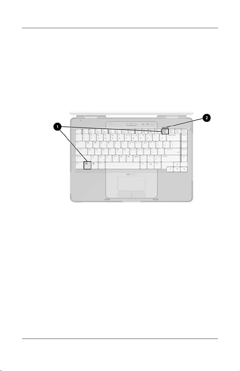
Keys
1
Component ID
Component Description
fn key Combines with other keys to perform system
1
Function keys (12) Perform system and application tasks. When
2
Hardware and Software Guide 1–1
tasks. For example, pressing fn+f7 decreases
screen brightness.
combined with fn, the function keys perform
additional tasks as hotkeys.
(Continued)
Page 10

Component ID
Keypad keys (15) Can be used like the keys on an external
3
numeric keypad.
Windows
4
applications
Windows logo key Displays the Microsoft® Windows® Start menu.
5
key
Displays a shortcut menu for items beneath the
pointer.
1–2 Hardware and Software Guide
Page 11
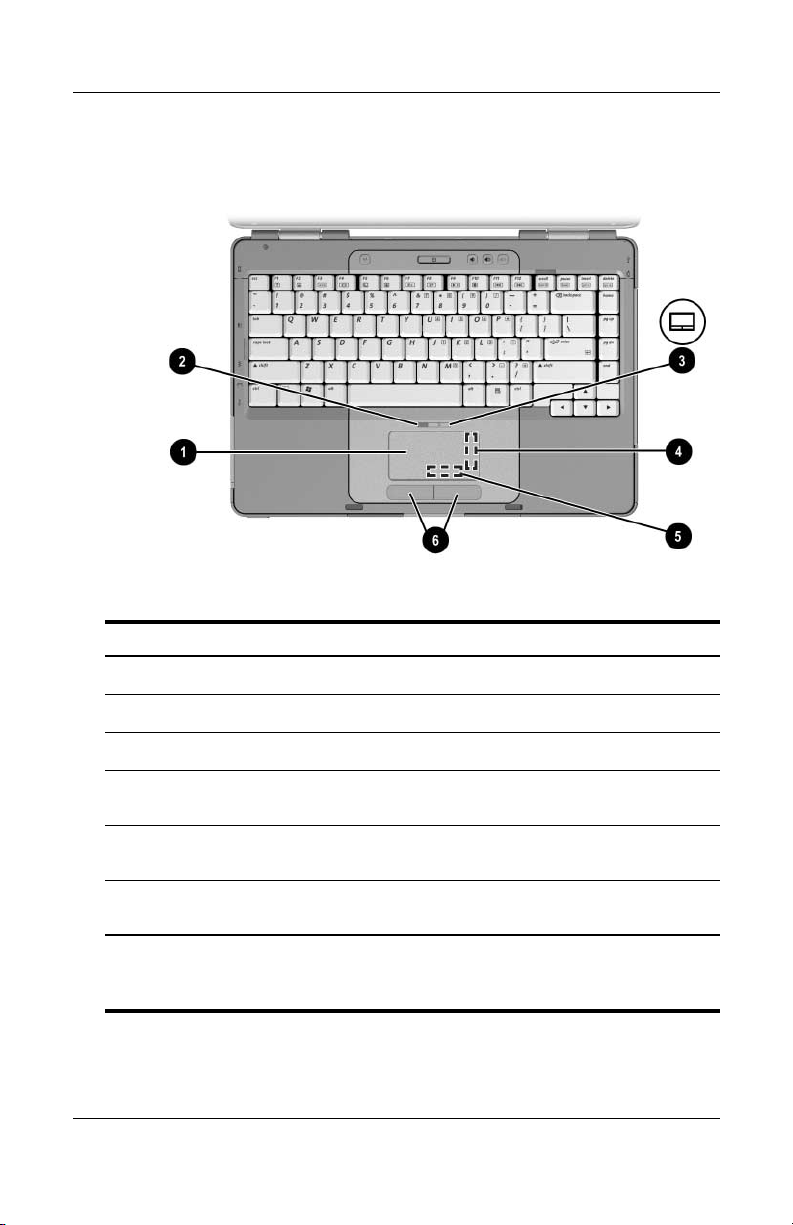
TouchPad
Component Description
Component ID
TouchPad* Moves the pointer.
1
TouchPad light On: TouchPad is enabled.
2
TouchPad button Enables/disables the TouchPad.
3
TouchPad vertical scrolling
4
region*
TouchPad horizontal scrolling
5
region
Left and right TouchPad
6
buttons*
*This table describes default settings. For information about changing the
functions of TouchPad components, refer to the
Preferences” section in Chapter 2, “Keyboard and Touchpad.”
Hardware and Software Guide 1–3
Scrolls upward or downward.
Scrolls toward left side or right side.
Function like the left and right buttons
on an external mouse.
“Setting TouchPad
Page 12
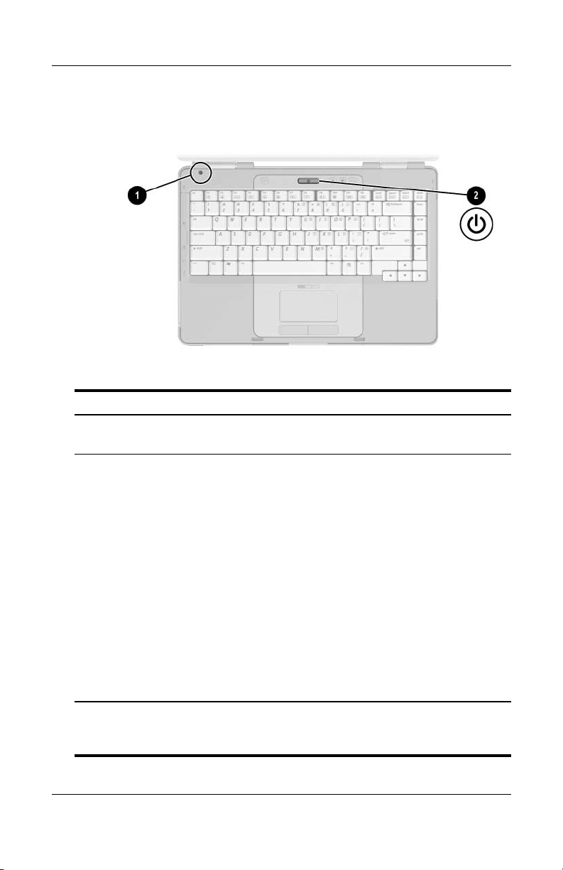
Component ID
Power Controls
Component Description
Display switch* If the notebook is closed while on,
1
Powe r butt on* When the notebook is
2
initiates standby.
■ Off, press to turn on the notebook.
■ On, briefly press to initiate
■ In standby, briefly press to resume
■ In hibernation, briefly press to
hibernation.
from standby.
restore from hibernation.
If the system has stopped
✎
responding and Windows
shutdown procedures cannot be
used, press and hold for at least
seconds to turn off the
4
notebook.
*This table describes default settings. For information about changing the
function of the display switch or power button, refer to the
Power Preferences” section in Chapter 3, “Power.”
1–4 Hardware and Software Guide
“Setting Other
Page 13

Lights
Component Description
Caps lock light On: Caps lock is on.
1
Component ID
Wireless light
2
3
4
5
*For information about establishing a wireless connection, refer to
Chapter 5, “Wireless (Select Models Only).”
†
There are 2 power/standby lights. Both lights display the same information.
The light on the power button is visible only when the notebook is open; the
other power/standby light is always visible on the front of the notebook.
Hardware and Software Guide 1–5
models only)
(select
Power/standby light
Mute light On: Volume is muted.
Num lock light On: Num lock or the embedded numeric
†
On: One or more optional internal wireless
devices, such as a WLAN and/or a
Bluetooth device, are turned
On: Notebook is turned on.
Blinking: Notebook is in standby.
Off: Notebook is off.
keypad is on.
on.*
Page 14

Component ID
Wireless and Volume Buttons
Component Description
Wireless button
1
2
3
4
1–6 Hardware and Software Guide
models only)
(select
Volume down button Decreases system volume.
Volume up button Increases system volume.
Volume mute button Mutes or restores volume.
Turns the wireless functionality on or
off, but does not create a wireless
connection.
To establish a wireless
✎
connection, a wireless network
must already be set up. For
information about establishing a
wireless link, refer to
“Wireless (Select Models Only).”
Chapter 5,
Page 15

Antennae
Component Description
Antennae (2)* Send and receive wireless device signals.
Exposure to Radio Frequency
Å
Radiation.
power of this device is below the
FCC radio frequency exposure limits.
Nevertheless, the device should be
used in such a manner that the
potential for human contact during
normal operation is minimized. To
avoid the possibility of exceeding
FCC radio frequency exposure
the
limits, human proximity to the
antennae should be not less than
cm (8 inches) during normal
20
operation, including when the
notebook display is closed.
The radiated output
Component ID
*The antennae are available on only select models. The antennae are not
visible from the outside of the notebook. For optimal transmission, keep the
areas immediately around the
Hardware and Software Guide 1–7
antennae free from obstructions.
Page 16

Component ID
Front Components
Lights
Component Description
Power/standby light* On: Notebook is turned on.
1
Blinking: Notebook is in standby.
Off: Notebook is off.
IDE (Integrated Drive
2
Electronics) drive light
On or blinking: The internal hard drive
or an optical drive is being accessed.
Battery light On: The battery pack is charging.
3
Blinking: The battery pack has
reached a low-battery condition.
Off: The battery pack is fully charged
or not inserted.
*
There are 2 power/standby lights. Both lights display the same information.
The light on the power button is visible only when the notebook is open; the
other power/standby light is always visible on the front of the notebook.
1–8 Hardware and Software Guide
Page 17

Component ID
Speakers, Jacks and Display Release Button
Component Description
Stereo speakers (2) Produce stereo sound.
1
Display release button Opens the notebook.
2
Audio-in
3
(microphone)
Audio-out
4
(headphone)
Hardware and Software Guide 1–9
jack
jack
Connects an optional monaural (single
sound channel) microphone.
Connects optional headphones or
powered stereo speakers. Also connects
the audio function of an audio/video
device such as a television or
VCR.
Page 18
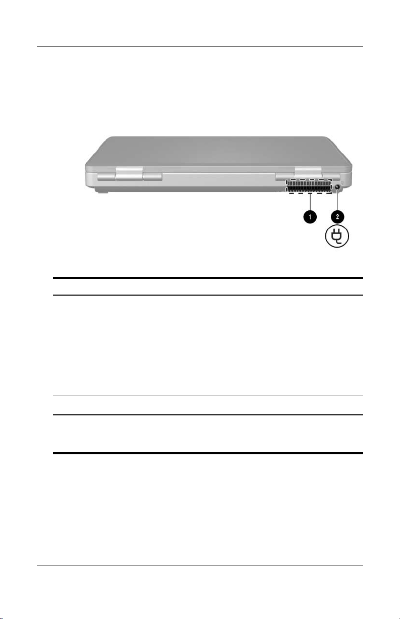
Component ID
Rear Components
Component Description
Exhaust vent* Provides airflow to cool internal
1
components.
To prevent overheating, do not
Ä
obstruct vents. Do not allow a
hard surface, such as a printer,
or a soft surface, such as pillows
or thick rugs or clothing, to block
airflow.
Power connector Connects the AC adapter cable.
2
*The notebook has 4 vents. This and all other vents are visible on the
bottom of the notebook. One vent is also visible on the left side of
notebook.
the
1–10 Hardware and Software Guide
Page 19

Left-Side Components
Ports and Jacks
Component ID
Component Description
External monitor port Connects an optional VGA monitor or
1
Expansion Port 2
2
3
4
5
*For expansion port signal information, refer to the “Expansion Port
Input/Output Signals” section in “Appendix A.”
†
The notebook has 3 USB ports. The other USB ports are on the right side
of the notebook.
Hardware and Software Guide 1–11
models only)*
(select
RJ-45 (network) jack Connects an optional network cable.
RJ-11 (modem) jack Connects the modem cable.
USB port
†
projector.
Connects the notebook to an optional
docking device.
Connects an optional USB device.
Page 20

Component ID
PC Card Slot and Button
Component Description
PC Card slot Supports an optional Type I or Type II
1
32-bit (CardBus) or 16-bit PC
Card.
PC Card eject button Ejects an optional PC Card from the
2
1–12 Hardware and Software Guide
PC Card slot.
Page 21

Vent and Security Cable Slot
Component Description
Exhaust vent* Provides airflow to cool internal
1
components.
Component ID
To prevent overheating, do not
Ä
obstruct vents. Do not allow a
hard surface, such as a printer,
or a soft surface, such as pillows
or thick rugs or clothing, to block
airflow.
Security cable slot Attaches an optional security cable to
2
*The notebook has 4 vents. This and all other vents are visible on the
bottom of the notebook. One vent is also visible on the rear of the notebook.
Hardware and Software Guide 1–13
the notebook.
The purpose of security
✎
solutions is to act as a deterrent.
These solutions do not prevent
the product from being
mishandled or stolen.
Page 22

Component ID
Right-Side Components
Component Description
USB ports (2)* Connect optional USB devices.
1
1394 port Connects an optional 1394a device
2
Memory Reader
3
4
1–14 Hardware and Software Guide
models only)
(select
Memory Reader light
models only)
(select
as a scanner, a digital camera,
such
a digital camcorder.
or
Supports an optional digital
memory
On: An optional digital memory card is
being accessed.
card.
†
(Continued)
Page 23

Component Description
Optical drive
5
‡
Supports an optical disc.
Component ID
S-Video–out jack
6
(select
models only)
Connects an optional S-Video device
such as a television, VCR, camcorder,
projector, or video capture card.
*The notebook has 3 USB ports. The other USB port is on the left side.
†
The digital memory card could be a Secure Digital (SD) Memory Card,
Memory Stick, Memory Stick Pro, xD-Picture Card, MultiMediaCard, or
SmartMedia (SM) card.
‡
The type of optical drive—for example, a DVD-ROM drive, a DVD/CD-RW
Combo Drive, or a DVD+RW/R and CD-RW Combo Drive—varies by
notebook model.
Hardware and Software Guide 1–15
Page 24

Component ID
Bottom Components
Mini PCI and Memory Compartments
Component Description
Mini PCI compartment Holds an optional wireless LAN device.
1
To prevent an unresponsive system
Ä
and the display of a warning
message, install only a Mini PCI
device authorized for use in your
notebook by the governmental
agency that regulates wireless
devices in your country. If you install
an unauthorized device and then
receive a warning message, remove
the device to restore notebook
functionality. Then contact
Customer
Memory compartment Contains 2 memory slots that support
2
1–16 Hardware and Software Guide
replaceable memory modules. The number
of preinstalled memory modules varies by
notebook model.
Care.
Page 25

Bays, Battery Latch and Vents
Component Description
Battery pack release latch Releases a battery pack from the
1
battery
bay.*
Component ID
Battery bay Holds a battery pack.
2
Exhaust vents (4)
3
Hard drive bay Holds the internal hard drive.
4
*Battery packs vary by model.
†
The notebook has 4 vents. One vent is also visible on the left side of the
notebook, and one vent is also visible on the rear of the notebook.
Hardware and Software Guide 1–17
†
Provide airflow to cool internal
components.
To prevent overheating, do not
Ä
obstruct vents. Do not allow a hard
surface, such as a printer, or a soft
surface, such as pillows or thick
rugs or clothing, to block airflow.
Page 26

Component ID
Additional Components
Hardware
The components included with your notebook vary by region,
country, notebook model, and the optional hardware you
purchased. The following sections identify the standard external
components included with most notebook models.
Component Description
AC adapter Converts AC power to DC power.
1
Power cord* Connects an AC adapter to an AC outlet.
2
Battery pack* Powers the notebook when the notebook is
3
Modem cable* Connects a modem to an RJ-11 telephone
4
Country-specific modem
5
adapter (included by
region as required)*
*Power cords, modem cables, and modem adapters vary in appearance by
region and country. Battery packs vary by model.
1–18 Hardware and Software Guide
not connected to external power.
jack or to a country-specific modem
adapter.
Adapts the modem cable to a non–RJ-11
(modem) jack.
Page 27

Optical Discs
Software on optical discs, such as CDs or DVDs, is included with
all notebook models.
■ The software packaged in the “Required for Setup” bag is not
preinstalled on your notebook. Depending on how you want
to use your notebook, you may want to install some or all of
these applications.
■ The software packaged in the “Save for Later” bag is
preinstalled or preloaded on your notebook. The software
discs are provided in case you ever need to repair or reinstall
this software.
Labels
The labels affixed to the notebook provide information you may
need when you troubleshoot system problems or travel
internationally with the notebook.
■ Service Tag—Provides the product name, product number
(P/N), and serial number (S/N) of your notebook. You may
need the product number and the serial number when you
contact Customer Care. The Service Tag label is affixed to
the bottom of the notebook. To display the information on the
Service Tag on your screen, select Start > Help and
Support.
Component ID
■ Microsoft Certificate of Authenticity—Contains the
Microsoft® Windows® Product Key. You may need the
Product Key to update or troubleshoot the operating system.
This certificate is affixed to the bottom of the notebook.
■ Regulatory label—Provides regulatory information about the
notebook. The Regulatory label is affixed to the inside of
battery bay.
the
Hardware and Software Guide 1–19
Page 28

Component ID
■ Modem Approval label—Provides regulatory information
■ Wireless certification labels—Some notebook models include
about the modem and lists the agency approval markings
required by some of the countries in which the modem has
been approved for use. You may need this information when
traveling internationally. The Modem Approval label is
affixed to the inside of the memory compartment cover.
an optional WLAN device and/or an optional Bluetooth®
device. If your notebook model includes one or more wireless
devices, a certificate providing regulatory information about
each device and the approval markings of some of the
countries in which the device has been approved for use is
included with your notebook. You may need this information
when traveling internationally. Wireless certification labels
are affixed to the inside of the Mini PCI compartment cover.
1–20 Hardware and Software Guide
Page 29
Keyboard and Touchpad
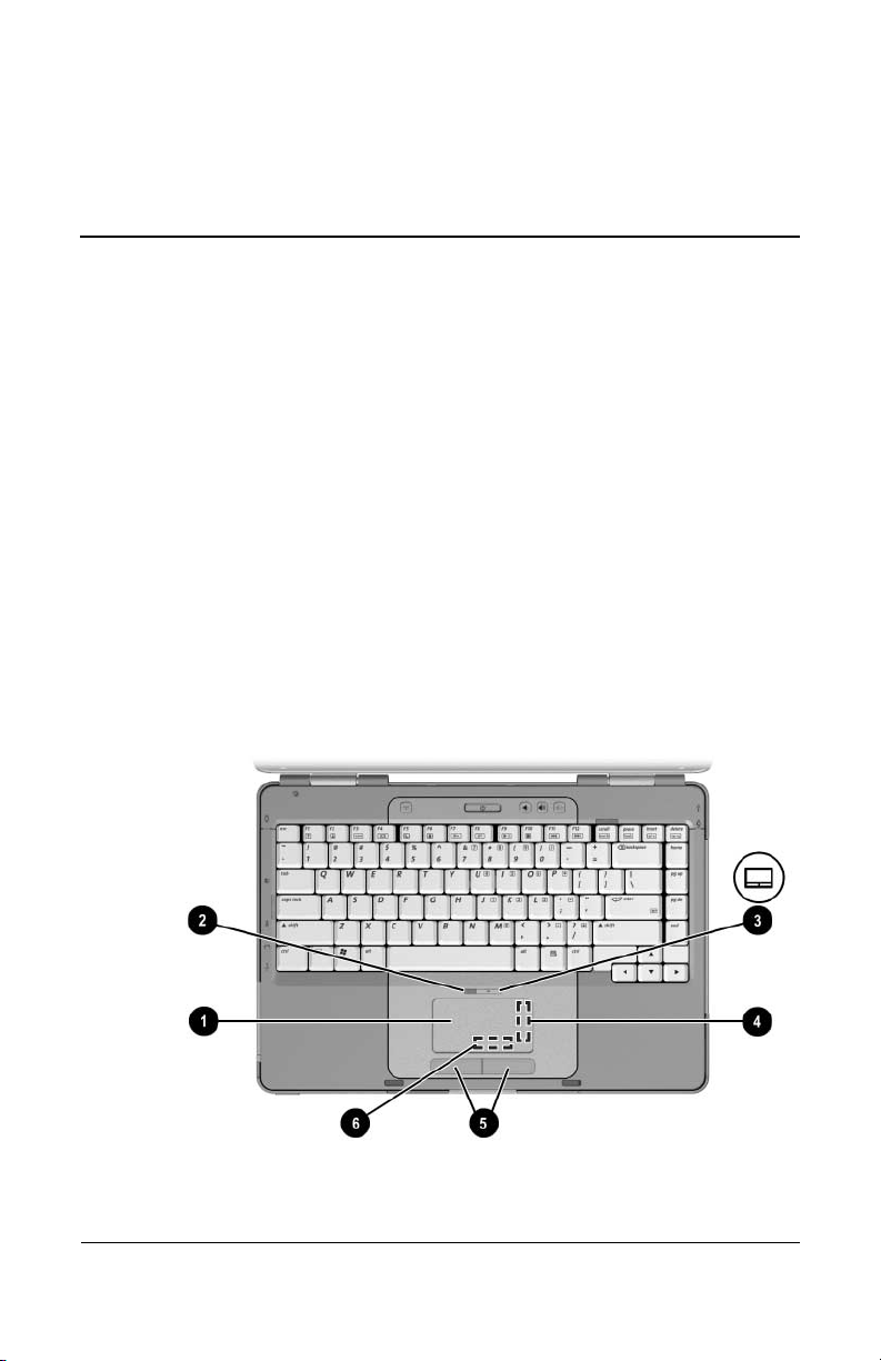
TouchPad
Identifying TouchPad Components
The TouchPad includes the following components:
2
TouchPad
1
TouchPad light
2
TouchPad button
3
TouchPad vertical scrolling region
4
Left and right TouchPad buttons
5
TouchPad horizontal scrolling
6
region
Hardware and Software Guide 2–1
Page 30

Keyboard and Touchpad
Using the TouchPad
The TouchPad provides the navigation, selection, and scroll
functions of an optional external mouse:
■ To move the pointer, slide your finger across the TouchPad
surface in the direction you want to move the pointer.
■ To execute the click functions of the left or right button on an
external mouse, press the left or right TouchPad button.
■ To scroll, place your finger onto a scrolling region, and then
slide your finger along the scrolling region in the direction
you want to scroll. (Sliding your finger from the TouchPad to
a scrolling region without first lifting your finger from the
TouchPad and then placing it on the scrolling region will not
activate the scrolling region.)
■ To enable or disable the TouchPad, press the TouchPad
button. When the TouchPad is enabled, the TouchPad light
on.
is
The TouchPad is enabled when the notebook is turned on.
you work with keystrokes rather than mouse actions, you
If
may prefer to disable the TouchPad to prevent accidental
TouchPad activity.
2–2 Hardware and Software Guide
Page 31

Setting TouchPad Preferences
In the Windows Mouse Properties window you can
■ Adjust basic pointing device settings such as click speed,
pointer speed and shape, and mouse trails.
■ Configure the right and left TouchPad buttons for
right-handed or left-handed use. These buttons are set by
default for right-handed use.
To access the Mouse Properties window:
» Select Start > Control Panel > Printers and Other
Hardware > Mouse.
All Windows instructions in your notebook documentation
✎
describe Microsoft Windows XP procedures based on the
default Windows XP category view. To change to Windows XP
classic view, select Start > Help and Support > Customizing
your computer > Files, folders, and programs
Windows classic folders.
Keyboard and Touchpad
> Use
In the TouchPad Properties window you can access additional
TouchPad preferences.
» To access the TouchPad Properties window, use the TouchPad
select Start > Control Panel > Printers and Other
to
Hardware > Mouse > Device Settings, and then select the
Settings button. (If
external mouse, the TouchPad Properties window may be
unavailable.)
Hardware and Software Guide 2–3
you follow this path using an optional
Page 32

Keyboard and Touchpad
Among the preferences available in the TouchPad Properties
window are
■ TouchPad Tapping, which enables you to tap the TouchPad
once to select an item or twice to double-click an item.
To access TouchPad Tapping settings, select Ta pp in g.
■ Edge Motion, which sets the TouchPad to continue cursor
movement when your finger reaches the edge of the
TouchPad.
To access Edge Motion settings, select Pointer Motion.
■ Long Distance Scrolling, which sets the scrolling region to
continue scrolling when your finger reaches the end of the
scrolling region.
To access Long Distance Scrolling, select Virtual Scrolling.
■ PalmCheck, which helps keep the TouchPad from being
accidentally activated while you are using the keyboard.
To access PalmCheck, select Sensitivity.
2–4 Hardware and Software Guide
Page 33

Hotkeys
Identifying Hotkeys
Hotkeys are preset combinations of the fn key 1, the esc key 2,
and one of the function keys 3.
The icons on the f1 through f12 keys represent hotkey functions.
Hotkey functions and procedures are described in the following
sections.
Keyboard and Touchpad
Hardware and Software Guide 2–5
Page 34

Keyboard and Touchpad
Hotkey Quick Reference
The following table identifies the default hotkey functions. The
function of the
refer to
the “Setting Other Power Preferences” section in
Chapter 3, “Power.”
Default Function Hotkey
Opens Help and Support Center. fn+f1
Opens print options window. fn+f2
Opens default Internet browser. fn+f3
Switches the image among displays. fn+f4
Initiates standby. fn+f5
Initiates QuickLock. fn+f6
Decreases screen brightness. fn+f7
Increases screen brightness. fn+f8
Plays, pauses, or resumes an audio CD or DVD. fn+f9
fn+f5 hotkey can be changed. For instructions,
Stops an audio CD or DVD. fn+f10
Plays the previous track or chapter on an audio CD
DVD.
or
Plays the next track or chapter on an audio CD or DVD. fn+f12
Displays system information.* fn+esc
*To clear the system information display, press esc.
2–6 Hardware and Software Guide
fn+f11
Page 35

Keyboard and Touchpad
Using Hotkey Procedures
Using Hotkeys On the Internal Keyboard
To use a hotkey command on the notebook keyboard, use either
of the following procedures:
■ Briefly press fn, and then briefly press the second key
the hotkey command.
of
■ Press and hold down fn, briefly press the second key of
hotkey command, and then release both keys at the
the
time.
same
Using Hotkeys on an External Keyboard
To use a hotkey command on an external keyboard, press the
scroll lock key twice, then the second key only of the hotkey
combination. For example, to use the
external keyboard, press
scroll lock+scroll lock+f5.
fn+f5 command on an
Using Hotkey Commands
Open Help and Support Center (fn+f1)
The fn+f1 hotkey opens the Help and Support Center.
In addition to providing information about your operating system,
the Help and Support Center provides
■ Information about your notebook, such as model and serial
number, installed software, hardware components, and
specifications.
■ Answers to questions about using your notebook.
■ Tutorials to help you learn to use notebook and operating
system features.
■ Updates for your operating system, drivers, and the software
provided on your notebook.
Hardware and Software Guide 2–7
Page 36

Keyboard and Touchpad
■ Checkups for notebook functionality.
■ Automated and interactive troubleshooting, repair solutions,
and system recovery procedures.
■ Links to Customer Care.
You can also access the Help and Support Center by selecting
Start > Help and Support.
Open Print Window (fn+f2)
In Windows the fn+f2 hotkey opens the print options window of
the active Windows application.
Open Internet Explorer (fn+f3)
The fn+f3 hotkey opens Internet Explorer.
■ Until you have set up your Internet or network services, the
fn+f3 hotkey opens the Windows Internet Connection Wizard.
■ After you have set up your Internet or network services and
your Web browser home page, you can use the
quickly access your
home page and the Internet.
fn+f3 hotkey to
2–8 Hardware and Software Guide
Page 37

Switch Image (fn+f4)
The fn+f4 hotkey switches the image among display devices
connected to the system. For example, if an optional monitor
connected to the notebook through the monitor port, each time
is
you press the
notebook display, the monitor display, and a simultaneous display
on both the notebook and the monitor.
Most monitors receive video information from the notebook
using the external VGA video standard. The
toggle images among other devices receiving video information
from the notebook.
The following video transmission types, with examples of devices
that use them, are supported by the
■ LCD (notebook display)
■ External VGA (most monitors)
■ S-Video (televisions, camcorders, VCRs, and video capture
boards with S-Video–in jacks)
■ Composite video (televisions, camcorders, VCRs, and video
capture boards with composite video-in jacks)
fn+f4 hotkey the image will switch among the
Keyboard and Touchpad
fn+f4 hotkey can also
fn+f4 hotkey:
Hardware and Software Guide 2–9
Page 38

Keyboard and Touchpad
Initiate Standby (fn+f5)
The fn+f5 hotkey is set by default to initiate standby.
When standby is initiated, your work is saved in random access
memory (RAM), the screen clears, and power is conserved.
While the notebook is in standby, the power/standby lights blink.
■ To initiate standby, the notebook must be on. If the notebook
is in hibernation, you must restore from hibernation before
you can initiate standby.
■ To resume from standby or restore from hibernation, briefly
press the power button.
For more information about using standby and hibernation, refer
Chapter 3, “Power.”
to
The function of the fn+f5 hotkey can be changed in the
operating
initiate hibernation instead of standby. In all Windows operating
system
hotkey. For information about changing the function of the
fn+f5 hotkey, refer to the “Setting Other Power Preferences”
section in Chapter 3, “Power.”
system. For example, you can set the fn+f5 hotkey to
windows, references to the sleep button apply to the fn+f5
For more information about using standby and hibernation, refer
Chapter 3, “Power.”
to
2–10 Hardware and Software Guide
Page 39

Initiate QuickLock (fn+f6)
The fn+f6 hotkey initiates the QuickLock security feature.
QuickLock protects your work by displaying the operating
system Log On window. While the Log On window is displayed,
the notebook cannot be accessed until a Windows user password
or a Windows administrator password is entered.
Before you can use QuickLock, you must set a Windows user
password or a Windows administrator password. For instructions,
refer to the Help and Support Center. To access the Help and
Support Center, press the fn+f1 hotkey or select Start > Help and
Support.
» To use QuickLock, press fn+f6 to display the Log On window
and lock the notebook. Then follow the instructions on the
screen to enter your Windows user password or your
Windows administrator password and access the notebook.
For information about combining Windows passwords with
Compaq passwords,
Chapter 6, “Security.”
Decrease Brightness (fn+f7)
Keyboard and Touchpad
The fn+f7 hotkey decreases the brightness of the notebook
screen.
screen dims. Decreasing screen brightness conserves power.
The longer you hold down the fn+f7 hotkey, the more the
» To increase screen brightness, press the fn+f8 hotkey.
Increase Brightness (fn+f8)
The fn+f8 hotkey increases the brightness of the notebook
screen.
screen brightens.
» To decrease screen brightness, press the fn+f7 hotkey.
Hardware and Software Guide 2–11
The longer you hold down the fn+f8 hotkey, the more the
Page 40

Keyboard and Touchpad
Media Activity Hotkeys (fn+f9 through fn+f12)
The following 4 media activity hotkeys can control the play of an
audio CD or a DVD. To control the play of a video CD, use the
media activity controls in your video CD player.
Play, Pause or Resume an Audio CD or a DVD
(fn+f9)
■ If the audio CD or the DVD is not playing, press the fn+f9
hotkey to begin or resume the play.
■ If the audio CD or the DVD is playing, press the fn+f9 hotkey
to pause the play.
Stop an Audio CD or a DVD (fn+f10)
The fn+f10 hotkey stops the play of an audio CD or a DVD.
You must stop a CD or DVD that is playing before you can
remove it from the optical drive.
Play Previous Track or Chapter of an Audio
CD or a DVD (fn+f11)
The fn+f11 hotkey plays the previous track of an audio CD or the
previous chapter of a DVD that is playing.
Play Next Track or Chapter of an Audio CD
a DVD (fn+f12)
or
The fn+f12 hotkey plays the next track of an audio CD or the next
chapter of a DVD that is playing.
2–12 Hardware and Software Guide
Page 41

Keyboard and Touchpad
Display System Information (fn+esc)
The fn+esc hotkey displays information about system hardware
components and software version numbers.
» To clear the display, press esc.
In the fn+esc display, the version of the system BIOS (basic
input-output system) is displayed as the BIOS date. On some
notebook models, the BIOS date is displayed in decimal format.
The BIOS date is sometimes called the system ROM version
number. For information about updating the system ROM, refer to
“Software Updates” section in Chapter 8, “Software Updates
the
and Recovery and System Software.”
Hardware and Software Guide 2–13
Page 42

Keyboard and Touchpad
Keypads
You can do keypad work with your notebook by using the
embedded numeric keypad in the notebook keyboard or by
connecting an optional external numeric keypad.
The embedded numeric keypad cannot be used while an external
keypad is connected to the notebook.
Using the Embedded Numeric Keypad
The embedded numeric keypad consists of 15 keys that can be
used like the keys on an external numeric keypad. When the
embedded numeric keypad is turned on, each keypad key
performs the functions indicated by the icon in the upper-right
corner of the key.
2–14 Hardware and Software Guide
Page 43
Keyboard and Touchpad
Turning the Embedded Numeric Keypad
On
and Off
When the embedded numeric keypad is off, press fn+num lk 1 to
turn the keypad on. The num lock light 2 is turned on.
When the embedded numeric keypad is on, press fn+num lk to turn
the keypad off. The num lock light is turned off.
Hardware and Software Guide 2–15
Page 44

Keyboard and Touchpad
Switching the Functions of Keypad Keys
You can temporarily switch the functions of an embedded
numeric keypad key between its standard function and its keypad
function.
■ To use a key on the keypad as a keypad key while the keypad
is turned off, press and hold
■ To use a key on the keypad as a standard key while the
keypad is turned on:
❏ Press and hold fn to type with the key in lowercase.
❏ Press and hold fn+shift to type with the key in uppercase.
Releasing fn returns a keypad key to its set function. For example,
a keypad key returns to its keypad function if the keypad is turned
on or to its standard function if the keypad is turned off.
fn while pressing the key.
Using an External Numeric Keypad
The embedded numeric keypad cannot be used while an
✎
optional external numeric keypad is connected to the notebook.
Most keys on most external numeric keypads function differently
depending on whether num lock mode is on or off. For example:
■ When num lock mode is on, most keypad keys type numbers.
■ When num lock mode is off, most keypad keys function like
the arrow, page up, or page down keys.
2–16 Hardware and Software Guide
Page 45

Keyboard and Touchpad
Turning Num Lock Mode On and Off
As
You Work
To turn num lock mode on or off on an external numeric keypad
as you work, press the
the notebook.
■ When an external numeric keypad is turned on and is in num
lock mode, the num lock light on the notebook is on.
■ When an external numeric keypad is turned off or is turned on
with num lock mode turned off, the num lock light on the
notebook is off.
num lk key on the external keypad, not on
Hardware and Software Guide 2–17
Page 46

Power Sources
Selecting a Power Source
Use the following table to select a recommended power source
for the way you plan to use the notebook.
Task Recommended Power Source
Work in most software
applications
■ Charged battery pack in the notebook
■ External power supplied through one of
the following devices:
❐ AC adapter
❐ Optional docking device
❐ Optional combination power adapter
3
Power
Charge or calibrate a
battery pack in the
notebook
Install or modify system
software or write to an
optical disc
Hardware and Software Guide 3–1
External power supplied through one of the
following devices:
■ AC adapter
■ Optional docking device
■ Optional combination power adapter
Do not charge the notebook battery
Å
pack onboard aircraft. Charging the
battery pack may damage aircraft
electronic systems.
External power supplied through one of the
following devices:
■ AC adapter
■ Optional docking device
Page 47

Power
Switching Between Battery and
External
Power
The notebook runs on external power whenever external power
available to the notebook. This conserves the charge in an
is
inserted battery pack. External power can be supplied through the
AC adapter, an optional docking device, or an optional
combination power adapter.
Because the notebook switches between battery power and
external power according to the availability of external power:
■ If the notebook is running on battery power and you connect
the notebook to external power, the notebook switches to
external power.
■ If the notebook is running on external power (and contains a
charged battery pack) and you disconnect the notebook from
external power, the notebook switches to battery power.
A Power Meter icon is displayed by default in the taskbar. The
Power Meter icon changes shape whenever the power source
changes between battery power and external power.
If the Power Meter icon is not displayed in your taskbar:
1. Select Start > Control Panel > Performance and
Maintenance > Power Options.
2. Select the Advanced tab.
3. Select the Always show icon on the taskbar check box.
4. Select OK.
3–2 Hardware and Software Guide
Page 48
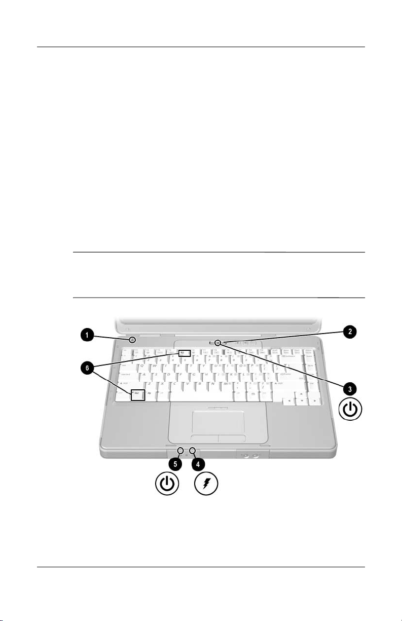
Power Control and Light Locations
This illustration is provided as a quick reference to the locations
of the power controls and lights on the notebook.
The function of each of these items is summarized in Chapter 1,
“Component ID.” Instructions for using these items are provided
in this chapter.
1 Display switch 4 Battery light
2 Power button 5 Power/standby light
3 Power/standby light 6 fn+f5 hotkey
The power/standby lights display identical information. The
✎
power/standby lights are visible when the notebook is open or
closed.
Power
Hardware and Software Guide 3–3
Page 49

Power
Standby, Hibernation and Shutdown Overviews
Standby
Standby reduces power to system components that are not in use.
When standby is initiated, your work is saved in random access
memory (RAM), the screen is cleared, and the power/standby
lights blink. Saving your work before initiating standby is not
usually necessary but is a recommended precaution. When you
resume from standby, your work is returned instantly to the
screen.
By default, the system initiates standby after 10 minutes of
notebook inactivity when the notebook is running on battery power
and after 25 minutes of inactivity when the notebook is running on
external power. For information about changing these settings,
refer to the
“Using Power Schemes”
section later in this chapter.
3–4 Hardware and Software Guide
Page 50

Hibernation
CAUTION: If the configuration of the notebook system is changed during
Ä
hibernation, it may not be possible to resume from hibernation. When the
notebook is in hibernation:
■ Do not add or remove a memory module.
■ Do not remove or replace the hard drive.
■ Do not connect or disconnect an external device.
■
Do not insert or remove a CD, DVD, PC Card, or digital memory card.
Hibernation saves your work to a hibernation file on the hard drive
and then shuts down the notebook. When hibernation is complete,
the power/standby lights are turned off.
When you restore from hibernation, your work is returned to the
screen where you left off. Restoring from hibernation takes a little
longer than resuming from standby but is much faster than
returning to your place manually after restarting the notebook.
To determine whether the notebook is in hibernation or turned
off, press the power button.
■ If the notebook is in hibernation, your work is returned to the
screen.
■ If the notebook is off, Windows loads.
Power
When the notebook is running on battery power, hibernation is
initiated by default after 30 minutes of notebook inactivity or
whenever the notebook reaches a critical low-battery condition.
Hibernation is enabled by default but can be disabled. To prevent
loss of work during a critical low-battery condition, disable
hibernation only during a battery pack calibration.
» To verify that hibernation is enabled, select Start >
Control
Options > Hibernate tab. If hibernation is enabled, the
Enable hibernation check box is selected.
Hardware and Software Guide 3–5
Panel > Performance and Maintenance > Power
Page 51

Power
Leaving Your Work
If you plan to resume shortly—Initiate standby for shorter times
and hibernation for longer times or for power conservation.
The amount of time a battery pack can support standby or
hibernation or hold a charge varies by notebook configuration and
the condition of the battery pack. Standby requires more power
than hibernation.
If you plan to resume within 2 weeks—Shut down the notebook. If
possible, connect the notebook to external power to keep an
inserted battery pack fully charged.
If the notebook will be unused and disconnected from external
power for more than 2 weeks—Shut down the notebook. To
extend the life of an inserted battery pack, remove the battery
pack and store it in a cool, dry location.
If an external power supply is uncertain—Initiate hibernation or
shut down the notebook. A power supply may become uncertain
because of such conditions as an electrical storm or a nearly
discharged battery pack.
Interference with Drive Media
To prevent the loss of playback or playback quality, do not initiate
standby or hibernation while playing a drive medium.
If standby or hibernation is initiated while a drive medium such as
a CD or DVD is in use, you may see the warning message
“Putting the computer into hibernation or standby may stop the
playback. Do you want to continue?” If the message is displayed,
select No. After you select No:
■ Playback may resume.
– or –
■ Playback may stop and the screen may be cleared. To return
to your work, press the power button and then restart the disc.
3–6 Hardware and Software Guide
Page 52

Power
Standby, Hibernation and Shutdown Procedures
This section explains the default standby, hibernation, and
shutdown procedures. For information about changing the
function of some of the power features on your notebook, refer to
“Power Preferences” section later in this chapter.
the
The controls and lights discussed in this section are illustrated in
in the
“Power Control and Light Locations” section earlier in this
chapter.
Turning the Notebook On or Off
Task Procedure Results
Turn on the
notebook.
Press the power button.
Pressing the power button
✎
turns on the notebook from
standby, hibernation, or
shutdown.
■ Power/standby
lights are
on.
turned
■ Operating system
is loaded.
Shut down the
notebook.
*If the system is unresponsive and you are unable to shut down the notebook
with this procedure, refer to the
section later in this chapter.
†
Depending on your network connections, the Turn Off Computer button may be
called the
Hardware and Software Guide 3–7
Shut Down
■ In Windows XP Home, select
Start > Turn Off Computer >
Turn Off.*
■ In Windows XP Professional,
select Start
Computer > Shut down > OK.*
button.
†
> Turn Off
“Using Emergency Shutdown Procedures”
■ Power/standby
lights are turned off.
■ Operating system
down.
is shut
■ Notebook is
†
turned
off.
Page 53

Power
Initiating or Resuming from Standby
Task Procedure Result
Initiate standby. With the notebook on, use any of
the following procedures:
■ Press the fn+f5 hotkey.
■ Close the notebook.
When the notebook is closed,
✎
the display presses the
display switch, which then
initiates standby.
■ In Windows XP Home,
Start > Turn Off
select
Computer > Stand By.*
■ In Windows XP Professional,
select Start > Turn Off
by > OK.*
Allow the system
to initiate
standby.
Computer > Stand
Stand by is not displayed,
(If
press the down arrow, and then
select Stand by from the
drop-down list.)
No action is required. The system
initiates standby
■ After 10 minutes of inactivity
while running on battery power.
■ After 25 minutes of inactivity
while running on external power.
■ Power/standby
lights blink.
■ Screen is cleared.
■ Power/standby
lights blink.
■ Screen is cleared.
Resume from
standby.
*Depending on your network connections, the Turn Off Computer button may be
called the
†
Depending on your notebook configuration, you may also be able to resume
from standby by moving or activating a control on an optional mouse or by
opening the display if the notebook was closed while in standby.
3–8 Hardware and Software Guide
Shut Down
■ Briefly press the power button.
– or –
■ Open the notebook.
button.
†
■ Power/standby
lights are turned on.
■ Yo u r w o r k i s
returned to the
screen.
Page 54

Initiating or Restoring from Hibernation
Hibernation cannot be initiated unless it is enabled. Hibernation
is enabled by default. To verify that hibernation remains enabled,
select Start > Control Panel > Performance and
Maintenance
is enabled, the Enable hibernation check box is selected.
Task Procedure Result
> Power Options > Hibernate tab. If hibernation
Power
Initiate
hibernation.
Allow the
system to
initiate
hibernation.
Restore from
hibernation.
*Depending on your network connections, the Turn Off Computer button may be
called the
†
If the system initiated hibernation because of a critical low-battery condition,
connect external power or insert a charged battery pack before you press the
power button. (The system may not respond if the drained battery pack is
the
Shut Down
only power source.)
In Windows XP Home, select
> Turn Off Computer.* Then hold
Start
down shift as you select the Stand By
button.
In Windows XP Professional,
Start > Turn Off Computer >
select
Hibernate.* (If Hibernate is not
displayed, press the down arrow, and
then select Hibernate from the
drop-down list.)
No action is required. If the notebook is
running on battery power and hibernation
is enabled, the system initiates
hibernation
■ After 30 minutes of notebook inactivity.
■ Whenever the battery pack reaches a
critical low-battery condition.
Press the power button.
button.
†
■ Power/standby
lights are
off.
turned
■ Screen is
cleared.
■ Power/standby
lights are
off.
turned
■ Screen is
cleared.
■ Power/standby
lights are
on.
turned
■ Yo u r w o r k i s
returned to the
screen.
Hardware and Software Guide 3–9
Page 55

Power
Using Emergency Shutdown Procedures
If the notebook does not respond to the standard Windows
shutdown procedure for your operating system, try the following
emergency shutdown procedures in the sequence provided:
■ Press ctrl+alt+del. Then
❏ In Windows XP Home, select Shut Down > Turn Off.
❏ In Windows XP Professional, select Shut down from the
drop-down list, and then select OK.
■ Press and hold down the power button for at least 4 seconds.
■ Unplug the notebook from external power and remove the
battery pack. For battery pack removal instructions refer to
the
“Replacing a Battery Pack” section later in this chapter.
3–10 Hardware and Software Guide
Page 56

Power Preferences
Using Power Schemes
A power scheme controls the amount of power the notebook uses
while running on external power or on a battery pack, and also
sets the notebook to initiate standby or hibernation after a period
of inactivity you specify.
» To select a preset power scheme or create a custom power
scheme, select Start > Control Panel > Performance and
Maintenance > Power Options, and then follow the
instructions on the screen.
Setting a Standby Password
To set the notebook to prompt for a password before resuming
from standby, select Start > Control Panel > Performance and
Maintenance > Power Options. Select the Advanced tab, select
the check box for Prompt for password when computer
resumes from standby, and then select OK. For information
about other passwords and security features, refer to
“Security.”
Power
Chapter 6,
Setting Other Power Preferences
You can change the function of the power button, the fn+f5
hotkey, and the display switch.
By default, when the notebook is on:
■ Briefly pressing the power button initiates hibernation.
■ Pressing the fn+f5 hotkey, called the sleep button in all
Microsoft operating systems, initiates standby.
■ Closing the notebook presses the display switch, which
initiates standby.
Hardware and Software Guide 3–11
Page 57

Power
To change the function of the power button, the fn+f5 hotkey, or
the display switch:
1. Select Start > Control Panel > Performance and
Maintenance
❏ To change the function of the power button, select a
> Power Options > Advanced tab.
function from the drop-down list for “When I press the
power button on my computer.”
❏ To change the function of the fn+f5 hotkey, select a
function from the drop-down list for “When I press the
sleep button on my computer.”
❏ To change the function of the display switch, select a
function from the drop-down list for “When I close the lid
of my portable computer.” (The function of the display
switch when you open the display is unaffected by these
settings. When you open the display while the notebook is
in standby, the display switch turns on the notebook.)
2. Select OK.
The Hibernate function is available in the power button, sleep
button, and display switch drop-down lists only if hibernation
enabled. If the Hibernate function is not available on these
is
select Start > Control Panel > Performance and
lists,
Maintenance
> Power Options > Hibernate tab. Select the
Enable hibernation check box, and then select OK.
3–12 Hardware and Software Guide
Page 58

Battery Pack
Charging a Battery Pack
To prolong battery life and optimize the accuracy of battery
charge displays:
■ If you are charging a new battery pack:
❏ Charge the battery pack while the notebook is connected
to external power through the AC adapter.
❏ When you charge the battery pack, charge it fully.
■ If you are charging an in-use battery pack:
❏ Allow the battery pack to discharge to about 10 percent
a full charge through normal use before charging it.
of
❏ When you charge the battery pack, charge it fully.
A battery pack inserted in the notebook charges whenever the
notebook is connected to external power through an AC adapter,
optional docking device, or an optional combination power
an
adapter.
Power
Hardware and Software Guide 3–13
Page 59

Power
Å
WARNING: Do not charge the notebook battery pack onboard
aircraft. Charging the battery pack may damage aircraft electronic
systems.
A battery pack inserted in the notebook charges whether the
notebook is off or in use, but the battery pack charges faster while
the notebook is off. Charging may be delayed if a battery pack is
new, has been unused for 2 weeks or more, or is much warmer or
cooler than room temperature.
The battery light displays charge status:
■ On: the battery pack is charging.
■ Blinking: the battery pack has reached a low-battery
condition and is not charging.
■ Off: the battery pack is fully charged or not installed.
For information about determining the amount of charge in a
battery pack, refer to the “Monitoring the Charge in a Battery
Pack” section next in this chapter.
3–14 Hardware and Software Guide
Page 60

Monitoring the Charge in a Battery Pack
Obtaining Accurate Charge Reports
To increase the accuracy of battery charge reports:
■ Allow a battery pack to discharge to about 10 percent of a full
charge through normal use before charging it.
■ When you charge a battery pack, charge it fully. The charge
in even a new battery pack may be reported inaccurately until
the battery pack has been fully charged at least once.
■ If a battery pack has been unused for one month or more,
calibrate the battery pack instead of simply charging it.
For information about battery calibration, refer to the
“Calibrating a Battery Pack” section later in this chapter.
Power
Hardware and Software Guide 3–15
Page 61

Power
Displaying Charge Reports
To display battery charge information on the screen, use the
operating system Power Meter feature. To access the Power
Meter display:
■ Select Start > Control Panel > Performance and
Maintenance > Power Options > Power Meter tab.
– or –
■ Select the Power Meter icon, which is displayed by default
in the taskbar. To display the Power Meter icon if the default
setting has been changed,
Performance and Maintenance > Power Options.
Advanced tab,
the
taskbar
check box, and then select
select the
Power Meter displays battery status in both percent and time:
■ The percent indicates the amount of charge remaining in the
battery pack.
■ The time indicates the approximate running time remaining
on the battery pack if the battery pack continues to provide
power at the current level. For example, the time remaining
will decrease if you start playing a DVD and will increase if
you stop playing a DVD.
select
Start > Control Panel >
Select
Always show icon on the
OK.
3–16 Hardware and Software Guide
Page 62

Managing Low-Battery Conditions
This section describes default low-battery condition alerts and
system responses. The default battery light responses cannot be
changed. To change other responses, select Start > Control
Panel > Performance and Maintenance > Power Options, and
then follow the instructions on the screen.
Identifying Low-Battery Conditions
When a battery pack that is the only power source for the
notebook reaches a low-battery condition, a text warning message
is displayed, and the battery light blinks.
If a low-battery condition is not resolved and the amount of
charge remaining in the battery pack continues to drop, the
notebook eventually enters a critical low-battery condition. If
notebook is on or in standby when a critical low-battery
the
condition is reached:
■ If hibernation is enabled, the system initiates hibernation.
Some unsaved work may be lost.
■ If hibernation is disabled, the notebook remains briefly in
standby, and then shuts
down. All unsaved work is lost.
Power
Hibernation is enabled by default. To verify that hibernation
remains enabled, select Start > Control Panel
> Performance
and Maintenance > Power Options > Hibernate tab. If
hibernation is enabled, the Enable hibernation check box is
selected.
Hardware and Software Guide 3–17
Page 63

Power
Resolving Low-Battery Conditions
CAUTION: To prevent problems when restoring from hibernation: If the
Ä
notebook has reached a critical low-battery condition and has begun to
initiate hibernation, do not restore power until hibernation is complete.
When hibernation is complete, the power/standby lights are turned off.
To resolve a low-battery condition:
■ If external power is available, connect the notebook to the
external power source.
■ If a charged battery pack is available, shut down the notebook
or initiate hibernation. Insert a charged battery pack, and then
turn on the notebook.
■ If no power source is available, save your work. Then initiate
hibernation or shut down the notebook.
3–18 Hardware and Software Guide
Page 64

Calibrating a Battery Pack
When to Calibrate
Even if a battery pack is heavily used, calibration should be
necessary only once a month. You do not have to calibrate a new
battery pack before first use.
Calibration does not usually increase battery run time, but it can
increase the accuracy of battery charge displays, especially under
the following conditions:
■ When the battery pack has been unused for one month
more.
or
■ When the notebook has been running primarily on
external
than
■ When battery charge displays report large changes in the
percent of power remaining within 2 minutes. For example,
if
remaining and then less than 2 minutes later displays only
5
remaining indicates that the battery pack needs calibration.
power (and rarely on battery power) for more
one month.
the Power Meter displays 20 percent of a full charge
percent of a full charge remaining, the rapid drop in charge
Power
For more information about battery charge displays, refer to
“Monitoring the Charge in a Battery Pack” section earlier
the
in this chapter.
Hardware and Software Guide 3–19
Page 65

Power
How to Calibrate
To calibrate a battery pack, you must fully charge, fully
discharge, and then fully recharge the battery pack.
Charging the Battery Pack
Charge the battery pack while the notebook is on. To charge the
battery pack:
WARNING: Do not charge the notebook battery pack onboard
Å
aircraft. Charging the battery pack may damage aircraft electronic
systems.
1. Insert the battery pack into the notebook.
2. Connect the notebook to external power through the
adapter or an optional combination power adapter. (The
AC
notebook battery light is on as the
3. Leave the notebook connected to external power until the
battery pack is fully charged. (The notebook battery light is
turned off.)
battery pack charges.)
Discharging the Battery Pack
CAUTION: To prevent loss of work, save your work before beginning
Ä
an unattended discharge procedure.
The notebook must remain on throughout the discharge process.
The battery pack can discharge whether or not you are using the
notebook, but the battery pack will discharge faster if the
notebook is in use.
3–20 Hardware and Software Guide
Page 66

Power
If you use the notebook occasionally during the discharge process
described below and have set energy-saving timeouts, expect the
following performance from your system during the discharge:
■ Any unsaved work from your current session will be lost
when the battery pack is fully discharged and the notebook is
shut down.
■ The system will not turn off a connected optional monitor.
■ The system will not decrease hard drive speed while the
notebook is idle.
■ System-initiated standby will not occur.
To fully discharge the battery pack:
1. Disable hibernation. To disable hibernation:
Select Start > Control Panel > Performance and
Maintenance
the Enable hibernation check box
> Power Options > Hibernate tab. Then clear
.
2. Display the settings on the Power Schemes tab. To access
Power Schemes tab:
the
Select Start > Control Panel > Performance and
Maintenance > Power Options > Power Schemes tab.
3. Record all settings in the Plugged in column and all settings
in the Running on batteries column, so you can reset them
after calibration.
4. Use the drop-down lists to set each item in both columns
Never.
to
5. Select OK.
6. Disconnect the notebook from the external power source,
do not turn off the notebook.
but
7. Run the notebook on battery power until the battery pack is
fully discharged. When the battery pack is fully discharged,
the notebook is shut down.
Hardware and Software Guide 3–21
Page 67

Power
Ä
Recharging the Battery Pack
CAUTION: To prevent an unintended battery drain and a potential loss
of work when the notebook reaches a critical low-battery condition,
reenable hibernation after calibrating the battery pack. To reenable
hibernation: Select Start > Control Panel > Performance and
Maintenance
Enable hibernation check box, and then select OK.
1. Connect the notebook to external power and maintain the
connection until the battery pack is fully recharged and the
battery light is turned off.
You can use the notebook while the battery pack is
recharging, but the battery pack will charge faster if the
notebook is turned off.
2. If the notebook is turned off, turn on the notebook when the
battery light is turned off, indicating that the battery pack is
fully charged.
3. Display the settings on the Power Schemes tab. To access
the
> Power Options > Hibernate tab. Select the
Power Schemes tab:
Select Start > Control Panel > Performance and
Maintenance > Power Options > Power Schemes tab.
4. Reenter the settings you recorded earlier for the items in the
Plugged in column and the Running on batteries column.
5. Select OK.
3–22 Hardware and Software Guide
Page 68

Conserving Battery Pack Power
To extend the time that a battery pack can run the notebook from
a single charge, use the following battery conservation settings
and procedures.
Conserving Power as You Work
To conserve power as you work:
■ Prevent devices you are not using from drawing power from
the notebook. For example:
❏ Turn off wireless and local area network (LAN)
connections and close modem applications.
❏ Disconnect from the notebook any external devices that
are not plugged into an external power source.
❏ Stop or remove an inserted PC Card.
❏ Disable or remove an inserted digital memory card.
❏ Turn off a device connected to the S-Video–out jack.
Power
■ Use optional, externally powered speakers instead of the
internal speakers whenever possible. When you use the
internal speakers, minimize system volume. Volume can be
adjusted with the volume buttons.
■ Minimize screen brightness.
❏ To decrease screen brightness, press the fn+f7 hotkey.
❏ To increase screen brightness, press the fn+f8 hotkey.
■ If you leave your work, initiate standby or hibernation, or
shut down the notebook.
Hardware and Software Guide 3–23
Page 69

Power
Selecting Power Conservation Settings
To set the notebook to use less power:
■ Select a short wait for the screen saver and select a screen
saver with minimal graphics and motion. To select a screen
saver and a screen saver wait time, select Start > Control
Panel > Appearance and Themes > Display > Screen
Saver tab, and then follow the instructions on the screen.
■ Select or create a power scheme that minimizes power use.
For more information about using power schemes, refer to the
“Using Power Schemes” section earlier in this chapter.
Replacing a Battery Pack
CAUTION: To prevent loss of work when removing a battery pack that
Ä
is the only power source, shut down the notebook or initiate hibernation
before removing the battery pack. (If you initiate hibernation, do not
begin the following procedure until the power/standby lights are turned
off, indicating that hibernation is complete.)
3–24 Hardware and Software Guide
Page 70
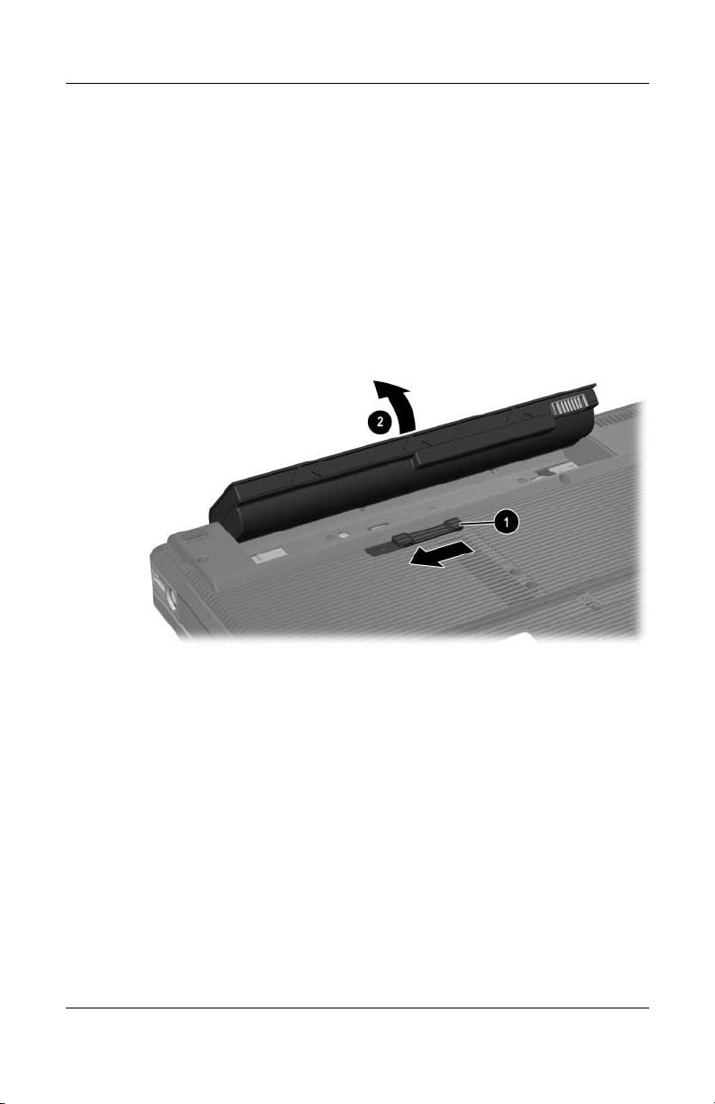
Removing a Battery Pack
Although battery packs vary by model, the removal procedure is
the same for all models.
To remove a battery pack:
1. Turn the notebook upside down.
2. Slide the battery release latch 1 to release the battery pack.
3. Pull the battery pack out of the battery bay 2.
Power
Hardware and Software Guide 3–25
Page 71

Power
Inserting a Battery Pack
Although battery packs vary by model, the insertion procedure is
the same for all models.
To insert a battery pack:
1. Turn the notebook upside down on a flat surface.
2. Insert the battery pack into the battery bay 1 and rotate the
battery pack 2 until it is seated.
3–26 Hardware and Software Guide
Page 72

Storing a Battery Pack
CAUTION: To prevent damage to a battery pack, do not expose it to
Ä
high temperatures for extended periods of time.
If the notebook will be unused and disconnected from external
power for more than 2
High temperatures, which may be present in parked cars or some
workplaces, accelerate the self-discharge rate of a stored battery
pack. To prolong the charge of a stored battery pack, place it in a
location that is cool and dry.
Calibrate a battery pack that has been stored for one month or
more before using it.
weeks, remove and store the battery pack.
Power
Hardware and Software Guide 3–27
Page 73

Power
Disposing of a Used Battery Pack
WARNING: To reduce the risk of fire or burns, do not disassemble,
Å
crush, or puncture a battery pack; short the external contacts on a
battery pack; or dispose of a battery pack in fire or water. Do not
expose a battery pack to high temperatures above 60°C (140°F).
Replace only with the HP battery pack approved for this computer.
When a battery pack has reached the end of its useful life, do not
N
dispose of the battery pack in general household waste. Follow the local
laws and regulations in your area for computer battery pack disposal.
In Europe, dispose of or recycle the battery packs by using the public
collection system or by returning them to HP, a service partner, or their
agents.
3–28 Hardware and Software Guide
Page 74
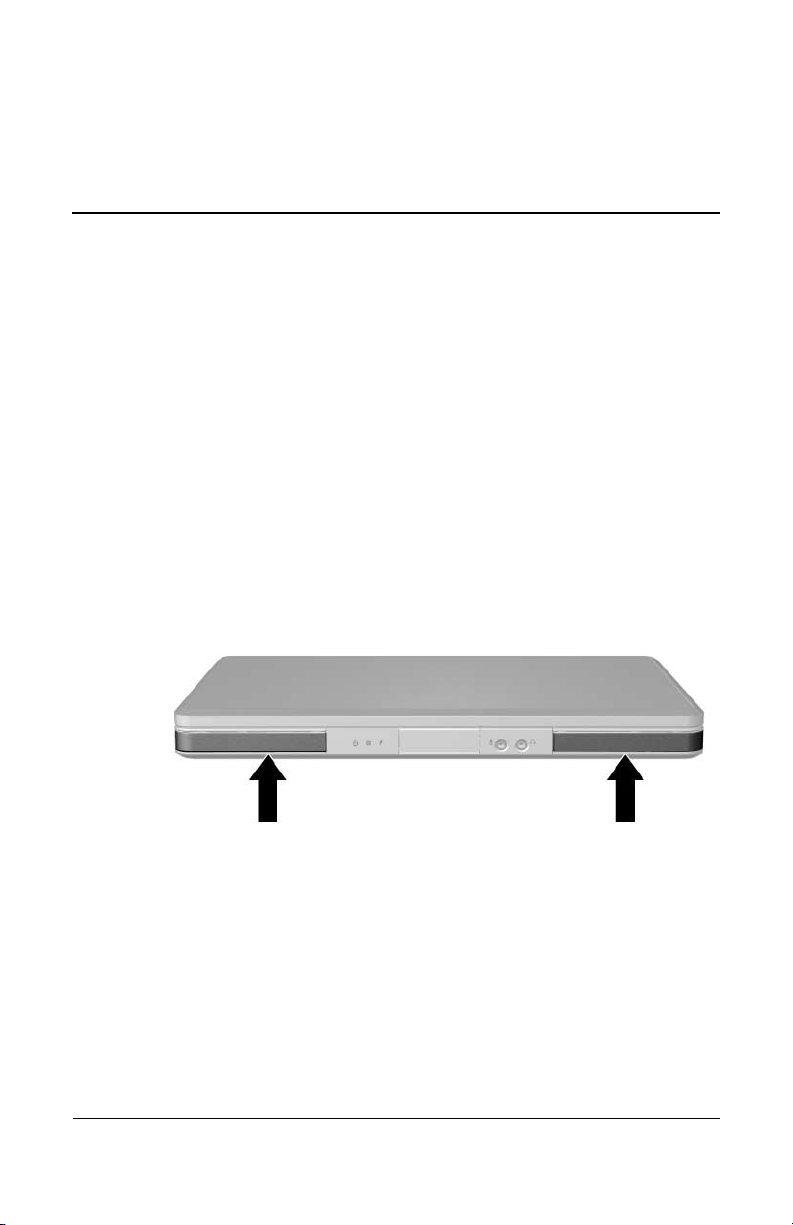
Internal Speakers
The internal speakers, identified in the following illustration, play
sound in stereo from applications, the operating system, games,
drive media, the Internet, and other sources.
If an external device, such as headphones, is connected to the
audio-out jack, the internal speakers are disabled.
4
Multimedia
Hardware and Software Guide 4–1
Page 75

Multimedia
Volume Controls
You can adjust volume with the volume buttons on the notebook
or the volume control software available in your operating system
and in some multimedia applications. The volume mute button on
the notebook overrides all software volume
■ To access the operating system volume controls, select
> Control Panel > Sounds, Speech, and Audio
Start
Devices > Sounds and Audio Devices, and then select the
Vo lu m e tab.
❏ To access additional sound quality settings, such as
balance, select the Advanced button in the Device
volume
❏ To display a volume icon on your taskbar, select the
check
then
■ To adjust volume using the notebook volume buttons:
❏ To decrease volume, press the volume down button 1.
❏ To increase volume, press the volume up button 2.
pane.
box for Place volume icon in the taskbar, and
select OK.
settings.
❏ To mute or restore volume, press the volume mute
3.
button
When volume is muted, the mute light (on the volume mute button)
is turned on. When volume is restored, the mute light is turned off.
4–2 Hardware and Software Guide
Page 76

Multimedia
External Audio Devices
Using the Audio-Out (Headphone) Jack
WARNING: To reduce the risk of personal injury, adjust the volume
Å
before putting on headphones.
CAUTION: To prevent possible damage to an external device, do not
Ä
plug a monaural (single sound channel) plug into the audio-out jack.
The audio-out jack, sometimes called a headphone jack, connects
optional headphones or externally-powered stereo speakers. The
audio-out jack, identified in the following illustration, is also used
to connect the audio functions of an audio/video device such as a
television or VCR.
When you connect a device to the audio-out jack, use only a
3.5-mm plug.
When a device is connected to the audio-out jack, the internal
speakers are disabled.
Hardware and Software Guide 4–3
Page 77
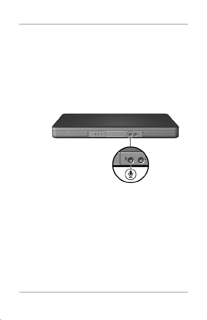
Multimedia
Using the Audio-In (Microphone) Jack
The audio-in jack, identified in the following illustration,
connects an optional monaural (single sound channel)
microphone. The audio-in jack is sometimes called a
microphone
It is recommended that you use an electret condenser microphone
with a 3.5-mm plug. If you connect a dynamic microphone, the
recommended sensitivity may not be achieved.
jack.
4–4 Hardware and Software Guide
Page 78

External Video Devices
Connecting an S-Video Device
Connecting the Audio
The S-Video–out jack, available only on select models, supports
video signals only.
If you are setting up a configuration that combines audio and
video functions, such as playing a DVD movie on your notebook
and displaying it on your television, you need a standard 3.5-mm
audio cable available from most computer or electronics retailers.
Plug the stereo end of the audio cable into the audio-out
(headphone) jack on the notebook. Plug the other end of the cable
into the audio-in jack on the external device. For more
information about the notebook audio-out jack, refer to the
“Using the Audio-Out (Headphone) Jack” section earlier in this
chapter.
S/PDIF audio support is only available through an optional
✎
expansion product.
Multimedia
Hardware and Software Guide 4–5
Page 79
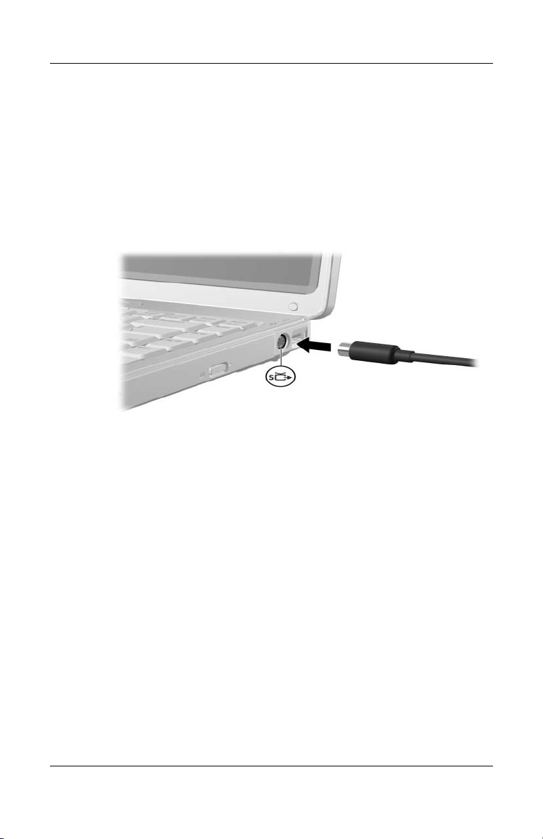
Multimedia
Connecting the Video
To transmit video signals through the S-Video–out jack, you need
a standard S-Video cable, available from most computer or
electronics retailers.
Plug one end of the S-Video cable into the notebook S-Video–out
jack, illustrated below. Plug the other end of the cable into the
S-Video–in jack on the external device.
Displaying a Video Image
To display an image on the notebook display or a video device
display, both the notebook and the video device must be
turned
on.
» To switch the image between the notebook display and the
video device display, repeatedly press the
Pressing the
fn+f4 hotkey switches the image among the
notebook display, any connected displays, and simultaneous
display.
For more information about fn+f4 and other hotkeys, refer to the
“Hotkeys” section in Chapter 2, “Keyboard and Touchpad.”
4–6 Hardware and Software Guide
fn+f4 hotkey.
Page 80

CD and DVD Procedures
Using Media Activity Hotkeys
Media activity hotkeys are preset combinations of the fn key 1
and 4 of the function keys. You can use these hotkeys to control
the play of an audio CD or a DVD that is inserted in the optical
drive. You can also use an optional remote control that is included
with some notebooks.
To control the play of an inserted video CD, use the media
activity controls in your video CD player application.
■ To play, pause, or resume an inserted audio CD or a DVD,
press the
■ To stop an inserted audio CD or a DVD that is playing, press
the
■ To play the previous track of an audio CD or the previous
chapter of a DVD that is playing, press the
■ To play the next track of an audio CD or the next chapter of a
DVD that is playing, press the
fn+f9 hotkey 2.
fn+f10 hotkey 3.
fn+f12 hotkey 5.
Multimedia
fn+f11 hotkey 4.
For more information about these and other hotkeys, refer to the
“Hotkeys” section in Chapter 2, “Keyboard and Touchpad.”
Hardware and Software Guide 4–7
Page 81

Multimedia
Protecting Playback
To prevent the loss of playback or playback quality:
■ Save your work and close all open applications before
playing a CD or a DVD.
■ Dock or undock the notebook from an optional docking
device before or after playing a disc, not while playing a disc.
To prevent the loss of playback while the notebook is in
Windows, do not initiate standby or hibernation while playing
a
disc. If standby or hibernation is initiated while a disc is in
you may see the warning message “Putting the computer
use,
Hibernation or Standby might stop the playback. Do you
into
want to continue?” If this message is displayed, select
you select No:
After
■ Playback may resume.
– or –
■ Playback may stop and the screen may clear. To return to
your work, press the power button and then restart the disc.
No.
Protecting a CD or DVD Write Process
CAUTION: To prevent loss of work and damage to a disc:
Ä
■ Before writing to a disc, connect the notebook to a reliable external
power source. Do not write to a disc while the notebook is running
on battery power.
■ Before writing to a disc, close all open applications (including
screen savers and antivirus software) except the disc software you
are using.
■ Do not copy directly from a source disc to a destination disc or from
a network drive to a destination disc. Instead, copy from a source
disc or network drive to your hard drive, and then copy from your
hard drive to the destination disc.
■ Do not use the notebook keyboard or move the notebook while the
notebook is writing to a disc. The write process is sensitive to
vibration.
4–8 Hardware and Software Guide
Page 82

Multimedia Software
The multimedia software included with your notebook is
determined by your region and notebook model.
The following list describes the capabilities of some of the
multimedia software that may be included with your notebook.
■ Windows Media Player—Plays audio CDs and DVDs, and
copies audio and data CDs. It also plays common audio and
video file types, such as MP3, WMA, AVI, MPG, and WMV.
This software is included with the Windows operating
system.
■ InterVideo WinDVD—Plays video CDs and DVD movies.
This software is preinstalled on select notebooks. You can
also obtain this software by any of the following methods:
❏ Install WinDVD from the Application and Driver
Recovery disc provided with most notebooks.
❏ If you do not have the Application and Driver Recovery
disc, contact Customer Care for a copy of the restore
solution for your notebook.
Multimedia
❏ Download the software from the technical support Web
http://www.compaq.com/consumersupport.
site at
Hardware and Software Guide 4–9
Page 83

Multimedia
■ InterVideo WinDVD Creator Plus—Provides the ability to
create, edit, and burn movies to a DVD or video CD. This
software is located on the InterVideo WinDVD Creator CD,
included with select notebooks.
■ Sonic RecordNow!—Enables you to create copies of data and
audio CDs and DVDs, and create personalized audio CDs and
DVDs. RecordNow! is preinstalled on select notebooks.
For more information about using multimedia software, refer
✎
to the online Help for the software.
Your notebook may include additional multimedia software. Be
sure to explore
■ Your desktop icons.
■ The software listed at Start > All Programs.
■ The preloaded items that may be available at Start > All
Programs > Software Setup.
Observing the Copyright Warning
It is a criminal offense, under applicable copyright laws, to make
unauthorized copies of copyright-protected material, including
computer programs, films, broadcasts, and sound recordings.
This notebook should not be used for such purposes.
4–10 Hardware and Software Guide
Page 84

Installing Software
To install software from a CD that is included with the notebook:
1. Connect the notebook to a reliable AC outlet.
2. Close any open applications.
3. Insert the CD into the optical drive.
❏ If autorun is enabled, an installation wizard is displayed.
❏ If autorun is disabled:
a. Select Start > Run.
b. Enter x:\setup.exe (where x is your CD drive
designation)
c. Select OK.
4. When the installation wizard is displayed, follow the
installation instructions on the screen.
5. Restart the notebook if prompted.
Repeat the installation procedure for all software you want to
✎
install.
Multimedia
WinDVD Creator has special drive requirements for proper
✎
installation. To install WinDVD Creator, refer to the instructions
provided with the InterVideo WinDVD Creator CD.
Hardware and Software Guide 4–11
Page 85

Multimedia
Enabling AutoPlay
AutoPlay is an option in Windows that turns the Autorun feature
on or off. Autorun starts a program or plays a title on a disc as
soon the disc is inserted into the drive and the drive door is
closed. By default, AutoPlay is enabled on the notebook.
To disable AutoPlay or to enable AutoPlay if the feature has been
turned off, refer to your operating system documentation or visit
the Microsoft Web site at
http://www.microsoft.com.
Changing DVD Region Settings
CAUTION: The region settings on your DVD drive can be changed only
Ä
times.
5
■ The region setting you select the fifth time becomes the permanent
region setting on the DVD drive.
■ The number of allowable region changes remaining on the drive is
displayed in the Remaining Times Until Permanent field in
the WinDVD window. The number in the field includes the fifth and
permanent change.
Most DVDs that contain copyrighted files also contain region
codes. The region codes help protect copyrights internationally.
You can play a DVD containing a region code only if the region
code on the DVD matches the region setting on your DVD drive.
If the region code on a DVD does not match the region setting on
your drive, a “Playback Of Content From This Region Is Not
Permitted” message is displayed when you insert the DVD. To
play the DVD, you must change the region setting on your DVD
drive. DVD region settings can be changed through the operating
system or through some DVD players.
4–12 Hardware and Software Guide
Page 86

Using the Operating System
To change settings through the operating system:
1. Open Device Manager by selecting Start > My Computer.
Right-click in the window and select Properties > Hardware
tab > Device Manager.
2. Select DVD/CD-ROM drives, right-click the DVD drive for
which you want to change region settings, and then select
Properties.
3. Make the desired changes on the DVD Region tab.
4. Select OK.
For additional information, refer to the Windows operating
system Help and Support.
Multimedia
Hardware and Software Guide 4–13
Page 87

Multimedia
Using WinDVD
To change the region settings on a drive using WinDVD:
1. Open WinDVD through one of the following methods:
❏ Select the WinDVD Player icon on the notification area.
❏ Select Start > (All) Programs > InterVideo WinDVD >
InterVideo WinDVD.
2. Right-click the WinDVD player window.
3. Select Setup.
4. Select the button for the region.
5. Select OK.
Using Other DVD Software
To change region settings on a drive using a DVD player other
than WinDVD, refer to the documentation provided with the
player.
4–14 Hardware and Software Guide
Page 88

(Select Models Only)
Wireless Features
If your notebook is equipped with an 802.11 wireless device
and/or a Bluetooth wireless device, you have a wireless notebook.
■ An 802.11 wireless notebook can connect to wireless local
area networks (WLANs) in corporate offices, your home,
and
public places such as airports, restaurants, coffee shops,
hotels, and universities. Hotspots are public places where
you
can access a wireless network. Contact your Internet
service provider (ISP) or search the Web for a list of hotspots
near you.
■ A Bluetooth wireless notebook can connect to other
Bluetooth wireless-enabled devices such as notebooks,
phones, printers, headsets, speakers, and cameras.
5
Wireless
Hardware and Software Guide 5–1
Page 89
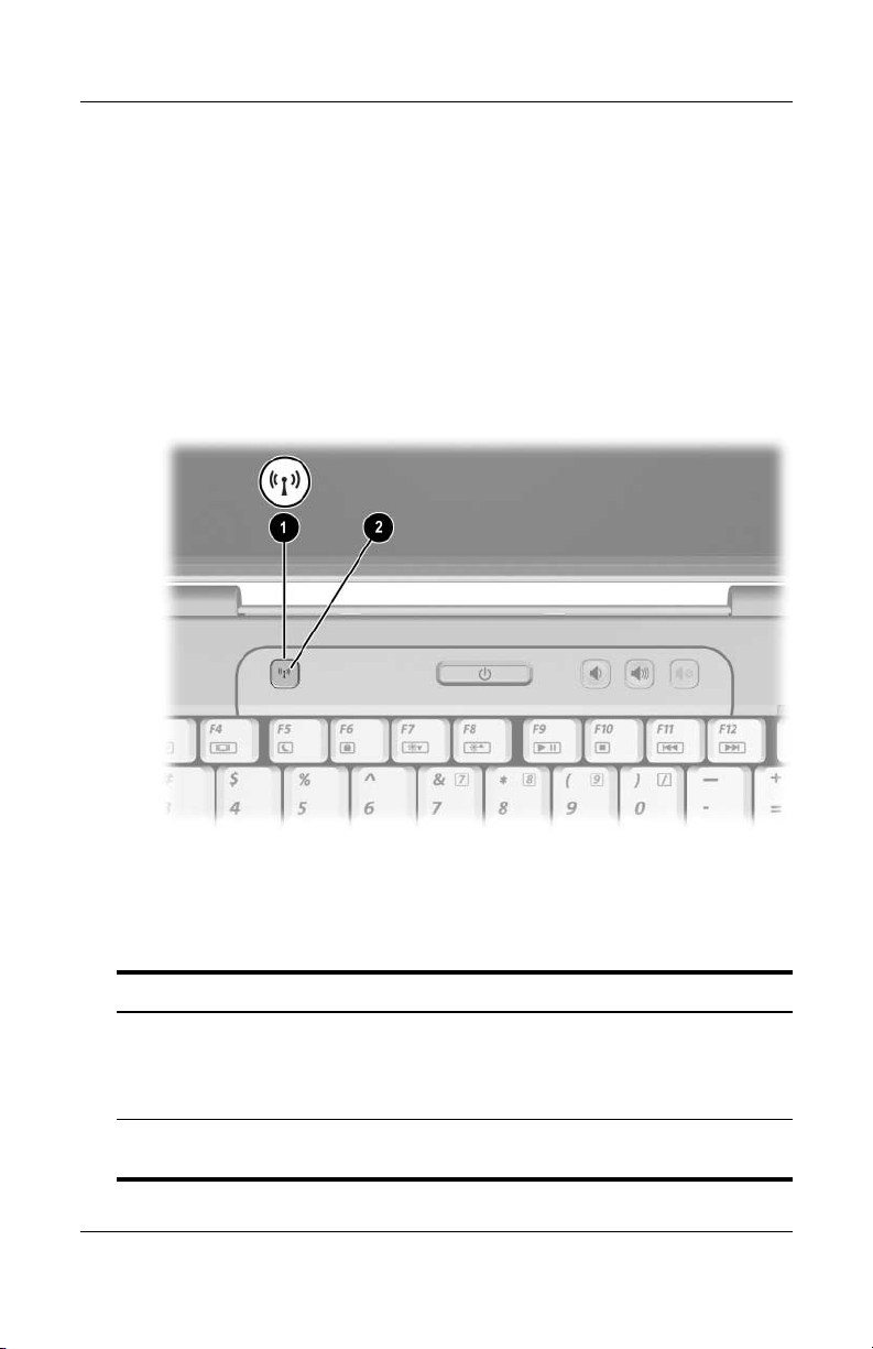
Wireless (Select Models Only)
Wireless Controls
Your notebook has a wireless button that can enable and disable
802.11 and Bluetooth wireless devices and wireless lights to
indicate the state of the wireless devices. By default, the 802.11
and Bluetooth wireless devices and wireless lights are turned on
when you turn on the notebook.
The following illustration shows the wireless button 1 and
wireless light 2.
In addition to the wireless button and wireless lights, your
wireless notebook may have the following software controls to
turn on, turn off, enable, and disable your wireless devices:
Wireless Control Description
Wireless Assistant utility
(select models only)
Wireless device controls
in the Setup utility
5–2 Hardware and Software Guide
Enables you to turn on and off 802.11 and
Bluetooth wireless devices individually. For
more information on using Wireless Assistant,
refer to
Enable and disable 802.11 and Bluetooth
wireless devices.
“Wireless Device Power States.”
Page 90

802.11 Wireless Devices
Wireless (Select Models Only)
(Select
With an 802.11 wireless device, you can access a wireless local
area network (commonly referred to as wireless network, wireless
LAN, or WLAN), which is composed of other computers and
accessories linked by a wireless router or a wireless access point.
■ A large-scale WLAN, such as a corporate or public WLAN,
■ A home or small office WLAN typically uses a wireless
There are 3 popular implementations of 802.11 wireless devices:
■ 802.11b
■ 802.11b/g
■ 802.11a/b/g
Models Only)
typically uses wireless access points that can handle a large
number of computers and accessories and can separate
critical network functions.
router, which enables several wireless and wired computers to
share an Internet connection, a printer, and files without
additional pieces of hardware or software. The terms wireless
access point and wireless router are often used
interchangeably.
Hardware and Software Guide 5–3
Page 91

Wireless (Select Models Only)
Computers with 802.11 wireless devices may support 1 or more
of 3 industry standards:
■ 802.11b, the first popular standard, supports data rates of up
to 11 Mbps and operates at a frequency of 2.4 GHz.
■ 802.11g supports data rates of up to 54 Mbps and operates at
a frequency of 2.4 GHz. An 802.11g WLAN device is
backward compatible with 802.11b devices, so they can
operate on the same network.
■ 802.11a supports data rates of up to 54 Mbps and operates at
a frequency of 5 GHz. 802.11a is not compatible with
802.11b and 802.11g.
For information on identifying the type of wireless device in your
computer, refer to
“Identifying an 802.11 Wireless Device.”
5–4 Hardware and Software Guide
Page 92

Wireless (Select Models Only)
Setting Up a WLAN in Your Home
Microsoft Windows XP supports WLAN configuration with the
Zero Client Configuration feature.
To set up a WLAN and connect to the Internet in your home, you
need the following equipment:
■ A broadband modem (either DSL or cable) 1
and high-speed Internet service purchased from an Internet
service provider (ISP).
■ A wireless router (purchased separately) 2.
■ Your wireless notebook 3, which varies in appearance by
model.
The illustration below shows an example of a completed wireless
network installation that is connected to the Internet.
As your network grows, additional wireless and wired computers
can be connected to the network to access the Internet.
If you need technical assistance to install your home WLAN,
✎
contact the router manufacturer or your ISP.
Hardware and Software Guide 5–5
Page 93

Wireless (Select Models Only)
Connecting to a WLAN in Your Home
To connect to a WLAN connection in your home:
■ Verify that all drivers required by your 802.11 wireless device
are installed and that the wireless device is correctly
configured.
If you are using an integrated 802.11 wireless device, all required
✎
drivers are installed and the device is preconfigured and ready
to
use.
■ Verify that your 802.11 wireless device is turned on. When
the wireless device is on, the wireless lights are turned on. If
the wireless lights are off, turn on the wireless device. For
information about turning on a wireless device, refer to
“Wireless Device Power States.”
■ Verify that your router is correctly installed and configured.
For instructions, refer to your router documentation.
■ Use the Wireless Network Connection feature of Microsoft
Windows XP to connect your notebook to the WLAN. For
additional information about this feature, select Start
and Support.
> Help
Functional range for subsequent WLAN connections will vary,
✎
depending on your computer WLAN implementation, router
manufacturer, and interference from walls and other electronic
devices.
For more information about connecting to a WLAN in
home:
your
■ Refer to information from your ISP and the documentation
included with your wireless router and other WLAN
equipment.
■ Access the information and Web site links provided at
Start
> Help and Support.
5–6 Hardware and Software Guide
Page 94

Wireless (Select Models Only)
Connecting to a Public WLAN
Contact your ISP or search the Web for a list of public WLANs
near you. Web sites that list public WLANs include Cisco
Hotspot Locator, Hotspotlist, and Geektools.
When you are within range of a public WLAN, a Wireless
Network Connection interactive message is displayed at the
bottom of your computer screen. Check with each public WLAN
location for cost and connection requirements.
Using Wireless Security Features
When you set up your home WLAN or access an existing public
WLAN, always ensure that security features are protecting the
WLAN. If you do not enable security on your WLAN, an
unauthorized wireless user can access your data and use your
Internet connection without your knowledge.
The most common security levels are Wi-Fi Protected Access
(WPA)-Personal and Wired Equivalent Privacy (WEP). In
addition to enabling WPA-Personal or WEP security encryption
on the router, you may want to use one or more of the following
security measures:
■ Change the default network name (SSID) and password.
■ Use a firewall.
■ Set security on your Web browser.
■ Enable MAC address filtering on the router.
Hardware and Software Guide 5–7
Page 95

Wireless (Select Models Only)
Identifying an 802.11 Wireless Device
You may need to know the name of the integrated 802.11 wireless
device installed in your notebook. To identify an integrated
802.11 wireless device:
1. Display the names of the network devices on your notebook:
a. Select Start > My Computer.
b. Right-click in the My Computer window.
c. Select Properties > Hardware tab > Device Manager >
Network Adapters.
2. Identify the 802.11 wireless device from the list that is
displayed:
❏ The listing for an 802.11 wireless device includes the term
wireless LAN, WLAN, or 802.11.
❏ If no 802.11 wireless device is listed, either your notebook
does not have an integrated 802.11 wireless device, or the
driver for the 802.11 wireless device is not properly
installed.
Troubleshooting Devices
For more troubleshooting information, you can access the
information at Start
5–8 Hardware and Software Guide
> Help and Support.
Page 96

Wireless (Select Models Only)
Bluetooth Wireless Devices
(Select
A Bluetooth wireless device provides short-range wireless
communications that replace the physical cable connections that
traditionally link electronic devices such as
■ Network access points.
■ Computers (desktop, notebook, PDA).
■ Phones (cellular, cordless, smart phone).
■ Imaging devices (printer, camera).
■ Audio devices (headset, speakers).
The devices are represented in the Bluetooth for Windows
software by graphical icons that resemble the physical features of
the devices.
The Bluetooth for Windows software provides the following
functions:
■ Personal Information Management (PIM) item
■ PIM synchronization—Synchronizes PIM data between a
■ File Transfer—Enables the exchange of files between
■ Network access (Personal Area Networking
Models Only)
transfer—Enables the exchange of information files such as
business cards, calendar items, notes, and message items
between Bluetooth computers or devices.
Bluetooth wireless device and a notebook, PDA, or cell
phone using Bluetooth.
Bluetooth computers or devices.
Profile)—Enables 2 or more Bluetooth devices to form an ad
hoc (peer-to-peer) network. Provides a mechanism that
enables a Bluetooth device to access a remote network
through a network access point. The network access points
can be traditional LAN data access points or group ad hoc
networks that represent a set of devices that are attached only
to one another.
Hardware and Software Guide 5–9
Page 97

Wireless (Select Models Only)
■ Dial-up networking—Connects Bluetooth devices to the
Internet.
■ Bluetooth serial port—Transfers data over the Bluetooth link
using a virtual COM port.
■ Hands-Free—Enables a vehicle-embedded, hands-free unit or
a notebook serving as a hands-free unit to establish a wireless
connection to a cellular phone and to act as the Bluetooth
cellular phone audio input and output mechanism.
■ Basic imaging—Provides a wireless connection between a
Bluetooth-enabled camera and other Bluetooth devices. The
camera can be controlled remotely by a notebook, and images
can be transferred from a camera to be stored on a notebook
or to be printed.
■ Human interface device—Provides a wireless connection to
other Bluetooth devices, such as keyboards, pointing devices,
gaming devices, and remote monitoring devices.
■ Fax—Provides a Bluetooth connection that enables a
notebook to send or receive a fax message using a Bluetooth
cellular phone or modem.
■ Headset—Provides a wireless connection between a headset
and a notebook or cellular phone. The headset acts as the
device’s audio input and output mechanism and increases
mobility.
5–10 Hardware and Software Guide
Page 98

Wireless (Select Models Only)
Wireless Device Power States
The wireless button 1 enables and disables 802.11 and Bluetooth
wireless devices, in conjunction with the Wireless Assistant
software utility. By default, any 802.11 or Bluetooth wireless
device and the wireless light 2 are turned on when you turn on
the notebook.
Turning on a wireless device does not automatically connect your
✎
notebook to a WLAN. For information on setting up a WLAN,
refer to “802.11 Wireless Devices (Select Models Only).”
Hardware and Software Guide 5–11
Page 99

Wireless (Select Models Only)
The 802.11 and Bluetooth wireless devices have 2 power states:
■ Enabled
■ Disabled
You can enable and disable the wireless devices with the wireless
button. You can also enable and disable the wireless devices in
the Setup utility.
You cannot use the wireless button or Wireless Assistant to
✎
control the wireless devices if they are disabled in the Setup
utility.
When the wireless devices are enabled with the wireless button,
you can use Wireless Assistant to turn the devices on or off
individually. When the wireless devices are disabled, you must
enable them before you can turn them on or off with Wireless
Assistant.
To view the state of the wireless devices, place the pointer
the Wireless Assistant icon in the notification area, or
over
Wireless Assistant by double-clicking the icon in the
open
notification area.
Wireless Assistant refers to an 802.11 wireless device as WLAN
✎
and Wireless LAN.
Wireless Assistant displays the status of the devices as on, off, or
disabled.
For more information about Wireless Assistant:
1. Open Wireless Assistant by double-clicking the icon in the
notification area.
2. Select the Help button.
You cannot use the wireless button or Wireless Assistant to
✎
control the wireless devices if they are disabled in the Setup
utility.
5–12 Hardware and Software Guide
Page 100

Turning On the Devices
If And Then
Wireless (Select Models Only)
■ Wireless
Assistant shows
that both WLAN
(802.11) and
Bluetooth are
turned off
■ Wireless light
is
off
■ Wireless
Assistant shows
that both WLAN
and Bluetooth
are disabled
■ Wireless light
off
is
■ Wireless
Assistant shows
that one device
is turned on and
the other device
is turned
off
■ Wireless light
on
is
You want to turn on
one or both devices
You want to turn on
one or both devices
You want to turn on
the device that is off
1. Right-click the Wireless
Assistant icon in the
notification area.
2. Select the device or
devices you want to turn
on.
If the wireless devices
✎
are turned off,
pressing the wireless
button disables both
devices. It does not
turn on the devices.
1. Press the wireless button.
(The devices return to their
previous on or off state.)*
2. If the wireless devices are
turned off, right-click the
Wireless Assistant icon in
the notification area.
3. Select the device or
devices you want to
turn
on.
1. Right-click the Wireless
Assistant icon in the
notification area.
2. Select the device you want
to turn on.
*Pressing the button does not turn on both devices.
If you want your wireless devices to be turned on when you turn
✎
on your notebook, you must turn them on before you shut down
or restart the notebook.
Hardware and Software Guide 5–13
 Loading...