

Page 1

REFERENCE GUIDE
Compaq Armada 3500
Family of Personal Computers
REFERENCE
GUIDE
Compaq Armada 3500 Family of Personal Computers
Page 2

Perf.
D
OCUMENTATION
Thank you for choosing Compaq!
Please help us provide quality support information by completing and
returning this postage-paid questionnaire.
1. Were you able to set up the computer using the setup poster?
❏ Yes ❏ No If not, at what point did you begin to have difficulty?
2. Was the online Reference Guide easy to find? ❏ Yes ❏ No
Is it easy to use? ❏ Yes ❏ No If not, why?
3. What computer task(s) will you need the most help with?
4. If you need help with a computer task, where will you get it?
5. What kind of references do you prefer? ❏ Online ❏ Printed Why?
6. In addition to a printed Reference Guide, how else would you prefer to
receive your information?
Rank 1 to 4 (1 is most preferred)
Guide preinstalled on computer
Guide on CD-ROM
Guide on Compaq web site
None of above
Additional Documentation Comments:
S
URVEY
Note: For comments not related to documentation, call
1-800-345-1518 (U.S.) or 1-800-567-1616 (Canada).
Name
Occupation
Company Phone No.
Street Address
City State Zip
Compaq Armada 3500 Family of Personal Computers
Writer: Johnnie Abercrombie Saved by: J Abercrombie Saved date: 08/12/98 1:50 PM
Part Number: File name: DOCSU.doc
Page 3

PerfPerf
Perf
Please do not staple
Fold here
Perf
Tape Tape
NO POSTAGE
NECESSARY
IF MAILED
IN THE
UNITED STATES
BUSINESS REPLY MAIL
FIRST-CLASS MAIL PERMIT NO. 400 HOUSTON, TX
POSTAGE WILL BE PAID BY ADDRESSEE
COMPAQ COMPUTER CORPORATION
ATTN: Portable PC Marketing Comm.
TOM HOWARD, MC 130805
P O BOX 692000
HOUSTON TX 77269-9976
Page 4

Notice
The information in this guide is subject to change without notice.
COMPAQ COMPUTER CORPORATION SHALL NOT BE LIABLE FOR
TECHNICAL OR EDITORIAL ERRORS OR OMISSIONS CONTAINED
HEREIN; NOR FOR INCIDENTAL OR CONSEQUENTIAL DAMAGES
RESULTING FROM THE FURNISHING, PERFORMANCE, OR USE OF
THIS MATERIAL.
This guide contains information protected by copyright. No part of this
guide may be photocopied or reproduced in any form without prior
written consent from Compaq Computer Corporation.
© 1998, 1999 Compaq Computer Corporation.
All rights reserved. Printed in Singapore.
C
OMPAQ
, A
, and LTE are registered in the U.S. Patent and
RMADA
Trademark Office.
Microsoft, MS-DOS, Windows, Windows NT, and other names of
Microsoft products mentioned herein are trademarks or registered
trademarks of Microsoft Corporation.
All other product names mentioned herein may be trademarks or
registered trademarks of their respective companies.
Software described herein is furnished under a license agreement or
nondisclosure agreement. The software may be used or copied only in
accordance with the terms of the agreement.
EFERENCE GUIDE
R
Compaq Armada 3500 Family of Personal Computers
Second Edition January 1999
First Edition September 1998
Part Number 310296-002
Compaq Computer Corporation
COMPAQ CONFIDENTIAL - NEED TO KNOW REQUIRED
Writer: Lorise Fazio Saved by: Johnnie Abercrombie Saved date: 12/07/98 11:19 AM
Pages: 2 Words: 185 Template: c:\template\ref\ref-ntc.dot
Page 5

ONTENTS
C
preface
U
SING THIS GUIDE
chapter 1
G
ETTING STARTED
Setting Up the Computer..................................................................1-1
Charging the Battery Pack for the First Time .............................1-1
Connecting the Power Cord.........................................................1-2
Opening the Computer.................................................................1-3
Turning On the Computer............................................................1-3
Setting Up the Software ...................................................................1-3
Operating the Computer During Setup........................................1-3
Choosing a Language...................................................................1-4
Removing the Operating System.................................................1-4
Restoring Your Operating System and
Software Preinstalled by Compaq ...............................................1-4
Completing Setup.............................................................................1-5
Registering the Computer............................................................1-5
Locating Online Resources..........................................................1-5
chapter 2
T
AKING A LOOK AT THE COMPUTER
Front Components............................................................................2-1
Left Side Components......................................................................2-2
Right Side Components....................................................................2-3
Rear Components.............................................................................2-4
Bottom Components.........................................................................2-5
Status Indicator Lights .....................................................................2-6
chapter 3
U
SING THE KEYBOARD AND POINTING DEVICE
Keyboard Components.....................................................................3-1
Special Keys.....................................................................................3-2
Using Hotkeys..................................................................................3-4
Embedded Numeric Keypad............................................................3-6
Contents v
COMPAQ CONFIDENTIAL - NEED TO KNOW REQUIRED
Writer: J Abercrombie Saved by: J Abercrombie Saved date: 12/08/98 10:17 AM
Pages: 8 Template: c:\templates\ref\ref-toc.dot
Part Number: 310296-002 File name: Toc.doc
Page 6

User Programmable Keys................................................................3-7
Assigning the User-Programmable Keys.................................... 3-8
Unassigning the User-Programmable Keys................................3-9
Adding Schemes.......................................................................... 3-9
Removing Schemes...................................................................3-10
Showing the Key Assignments in the System Tray..................3-10
Using the Pointing Stick................................................................3-11
Using Two-Dimensional Features............................................. 3-11
Using Three-Dimensional Features........................................... 3-12
Customizing the Settings........................................................... 3-12
Replacing the Pointing Device Rubber Cap .............................3-12
Customizing the Pointing Stick Controls..................................3-12
chapter 4
U
SING BATTERY PACKS
Learning About Batteries................................................................. 4-1
Using a New Battery Pack............................................................... 4-1
Charging Battery Packs ................................................................... 4-2
Using the Battery Gauge..................................................................4-3
Ensuring Battery Gauge Accuracy .................................................. 4-3
Identifying a Low Battery Condition ..............................................4-4
Resolving a Low Battery Condition by
Connecting the Power Cord ........................................................ 4-5
Resolving a Low Battery Condition by
Connecting the Automobile/Aircraft Adapter............................. 4-6
Resolving a Low-Battery Condition with a
Charged Battery Pack.................................................................. 4-7
Resolving a Low Battery Condition When
No Power Source Is Available .................................................... 4-7
Inserting and Removing Battery Packs ........................................... 4-8
Removing the Battery Pack from the Battery Bay...................... 4-8
Inserting the Battery Pack into the Battery Bay.......................... 4-9
Storing Battery Packs.....................................................................4-10
Maximizing Battery Pack Life....................................................... 4-10
Recycling Used Battery Packs.......................................................4-11
System Beeps................................................................................. 4-11
Beeps with a Blinking Battery Charge Light............................ 4-11
Beeps with a Blinking Power/Suspend Light ........................... 4-12
Turning Beeps On or Off...........................................................4-12
a.
vi Contents
COMPAQ CONFIDENTIAL - NEED TO KNOW REQUIRED
Writer: J Abercrombie Saved by: J Abercrombie Saved date: 12/08/98 10:17 AM
Part Number: 310296-002 File name: Toc.doc
Page 7

chapter 5
C
OMPUTER POWER AND POWER MANAGEMENT
Leaving On the Computer................................................................5-1
Turning Off the Computer ...............................................................5-1
Restarting the Computer ..................................................................5-2
Disconnecting the Computer from External Power.........................5-3
Managing Power ..............................................................................5-3
Setting the Battery Conservation Level...........................................5-5
Using ACPI Power Control..............................................................5-6
Using Hibernation............................................................................5-6
Enabling Hibernation...................................................................5-7
Initiating Hibernation...................................................................5-7
Exiting Hibernation......................................................................5-7
Disabling Hibernation..................................................................5-8
Using Suspend..................................................................................5-8
Identifying a Suspend Condition.................................................5-9
Initiating Suspend........................................................................5-9
Exiting Suspend...........................................................................5-9
Using Timeouts ..............................................................................5-10
Setting Component Timeouts....................................................5-10
Setting the Screen Saver............................................................5-11
chapter 6
W
ORKING WITH REMOVABLE DRIVES AND DEVICE BAYS
Bay Configuration............................................................................6-1
Caring for Removable Drives ..........................................................6-2
Using the Diskette Drive..................................................................6-3
Connecting the External Diskette Drive......................................6-3
Connecting and Disconnecting the Adapter................................6-3
Selecting Diskettes.......................................................................6-3
Inserting a Diskette......................................................................6-4
Removing a Diskette....................................................................6-5
a.
Contents vii
COMPAQ CONFIDENTIAL - NEED TO KNOW REQUIRED
Writer: J Abercrombie Saved by: J Abercrombie Saved date: 12/08/98 10:17 AM
Part Number: 310296-002 File name: Toc.doc
Page 8

chapter 7
U
SING THE MOBILE
3500 E
XPANSION UNIT
Connecting the Computer to the
Mobile 3500 Expansion Unit........................................................... 7-1
Disconnecting the Computer from the
Mobile 3500 Expansion Unit........................................................... 7-3
MultiBay Devices ............................................................................ 7-5
MultiBay Weight Saver...............................................................7-5
Inserting Devices into the MultiBay ........................................... 7-5
Removing Devices from the MultiBay ....................................... 7-7
Boot Sequencing.......................................................................... 7-8
Using the Optical Disc Bay ............................................................. 7-8
Inserting a Disc into the CD-ROM Drive or
DVD-ROM Drive........................................................................ 7-8
Removing a Disc from the CD-ROM Drive or
DVD-ROM Drive...................................................................... 7-10
chapter 8
C
ONNECTING EXTERNAL DEVICES
Connecting an External Enhanced Keyboard.................................. 8-1
Connecting an External Monitor ..................................................... 8-1
Connecting a Mouse or Other External Pointing Device................ 8-2
Connecting a Serial Printer.............................................................. 8-2
Connecting a Parallel Printer........................................................... 8-3
Connecting Infrared Equipment ...................................................... 8-4
Connecting USB Peripherals...........................................................8-5
Docking the Computer and Mobile 3500 Expansion Unit
to the Convenience Base..................................................................8-5
Undocking the Computer and Mobile 3500 Expansion Unit
from the Convenience Base.............................................................8-6
a.
viii Contents
COMPAQ CONFIDENTIAL - NEED TO KNOW REQUIRED
Writer: J Abercrombie Saved by: J Abercrombie Saved date: 12/08/98 10:17 AM
Part Number: 310296-002 File name: Toc.doc
Page 9

chapter 9
U
PC C
SING
ARDS
PC Card Types..................................................................................9-1
Inserting a PC Card..........................................................................9-1
Removing a PC Card........................................................................9-3
PC Card Device Drivers...................................................................9-4
Changing PC Card Settings..............................................................9-4
Managing PC Card Power................................................................9-5
Zoomed Video..................................................................................9-5
Stopping a PC Card..........................................................................9-5
chapter 10
U
SING AUDIO FEATURES
Audio Components Overview........................................................10-1
Identifying the Audio Components................................................10-2
Using Internal and External Microphones.....................................10-3
Using Internal and External Speakers/Headphones.......................10-3
Controlling Audio Volume ............................................................10-4
chapter 11
U
PGRADING THE COMPUTER
Upgrading System Memory...........................................................11-1
Checking the Amount of Memory.............................................11-1
Obtaining an Optional Memory Expansion Board....................11-2
Inserting a Memory Expansion Board.......................................11-2
Removing a Memory Expansion Board ....................................11-3
Upgrading the Hard Drive..............................................................11-4
Adding a DVD-ROM Drive...........................................................11-4
a.
chapter 12
M
AINTENANCE AND TRAVEL GUIDELINES
Caring for the Computer ................................................................12-1
Caring for the Display................................................................12-2
Traveling with the Computer.........................................................12-3
Shipping the Computer ..................................................................12-4
Operating Temperatures.................................................................12-4
Contents ix
COMPAQ CONFIDENTIAL - NEED TO KNOW REQUIRED
Writer: J Abercrombie Saved by: J Abercrombie Saved date: 12/08/98 10:17 AM
Part Number: 310296-002 File name: Toc.doc
Page 10

chapter 13
S
ECURITY FEATURES
Types of Security........................................................................... 13-1
Using the Cable Lock .................................................................... 13-2
Using Passwords Properties........................................................... 13-3
Using the Power-On Password......................................................13-3
Establishing the Power-On Password ....................................... 13-3
Entering the Power-On Password ............................................. 13-5
Changing the Power-On Password............................................ 13-6
Deleting the Power-On Password ............................................. 13-8
If You Forget Your Power-On Password..................................13-9
Using the Quick Controls .............................................................. 13-9
Enabling the Quick Controls................................................... 13-10
Initiating the Quick Controls...................................................13-10
Using the Setup Password ...........................................................13-11
Establishing the Setup Password............................................. 13-11
Entering the Setup Password...................................................13-12
Changing the Setup Password................................................. 13-12
Deleting the Setup Password...................................................13-15
Enabling and Disabling Devices.................................................. 13-16
DriveLock Overview ................................................................... 13-17
User and Master Passwords Overview....................................13-17
Establishing DriveLock Protection.........................................13-18
Changing the User Password................................................... 13-20
Removing DriveLock Protection ............................................ 13-21
Changing the Master Password............................................... 13-22
a.
chapter 14
I
NTELLIGENT MANAGEABILITY
Intelligent Manageability Overview.............................................. 14-1
Asset Management.........................................................................14-2
Changing the Asset Tag Number..............................................14-2
Fault Management ......................................................................... 14-3
Fault Management Alerts..........................................................14-3
Security Management....................................................................14-4
Configuration Management........................................................... 14-4
x Contents
COMPAQ CONFIDENTIAL - NEED TO KNOW REQUIRED
Writer: J Abercrombie Saved by: J Abercrombie Saved date: 12/08/98 10:17 AM
Part Number: 310296-002 File name: Toc.doc
Page 11

chapter 15
C
OMPUTER SETUP AND DIAGNOSTICS UTILITIES
Computer Setup Overview.............................................................15-1
Running Computer Setup ..........................................................15-2
Exiting Computer Setup ............................................................15-3
Using Compaq Utilities..................................................................15-3
Running Compaq Diagnostics .......................................................15-4
Using the Diagnostics Utilities.......................................................15-4
Running Computer Checkup (TEST)........................................15-5
Running View System Information (INSPECT).......................15-6
Using the Video Utility..................................................................15-6
Ordering Preinstalled Software......................................................15-7
Boot Sequencing ............................................................................15-7
chapter 16
T
ROUBLESHOOTING
Troubleshooting Checklist.............................................................16-1
Solving Software Application Problems................................. 16-21
appendix A
C
OMPAQ CUSTOMER SUPPORT
Preparing for a Technical Support Call ..........................................A-1
Worldwide Telephone Numbers.....................................................A-2
a.
appendix B
R
EGULATORY NOTICES
Regulatory Agency Series Numbers............................................... B-1
Federal Communications Commission Notice ............................... B-2
Modifications..............................................................................B-2
Cables..........................................................................................B-2
Declaration of Conformity for Products Marked
with the FCC Logo (United States only).................................... B-2
Contents xi
COMPAQ CONFIDENTIAL - NEED TO KNOW REQUIRED
Writer: J Abercrombie Saved by: J Abercrombie Saved date: 12/08/98 10:17 AM
Part Number: 310296-002 File name: Toc.doc
Page 12

Canadian Notice...............................................................................B-3
Avis Canadien..................................................................................B-3
European Notice...............................................................................B-3
Japanese Notice................................................................................B-4
German Ergonomics Notice.............................................................B-4
Airline Travel Notice.......................................................................B-4
Energy Star Compliance..................................................................B-4
Battery Notice..................................................................................B-5
Power Cords.....................................................................................B-5
AC Adapter......................................................................................B-6
Laser Safety......................................................................................B-6
CDRH Regulations......................................................................B-6
appendix C
E
LECTROSTATIC DISCHARGE
Preventing Electrostatic Discharge..................................................C-1
When Handling Removable Drives.............................................C-1
When Installing Internal Components ........................................C-2
Grounding Methods.........................................................................C-2
appendix D
S
PECIFICATIONS
...................................................................................... D-1
I
......................................................................................................I-1
NDEX
xii Contents
a.
COMPAQ CONFIDENTIAL - NEED TO KNOW REQUIRED
Writer: J Abercrombie Saved by: J Abercrombie Saved date: 12/08/98 10:17 AM
Part Number: 310296-002 File name: Toc.doc
Page 13

preface
SING THIS GUIDE
U
Some or all of the following format conventions are used in this
guide to distinguish elements of text:
Names of keys are shown in bold type as they appear on the
■
keyboard, for example,
Keys that you should press at the same time are represented by
■
the key names and the plus (+) symbol, for example,
Ctrl+Alt+Delete.
Commands are presented in lowercase, bold type as shown
■
here:
An arrow symbol is used to separate icons or menu options
■
that you should select in succession; for example, click the
Start buttonÆSettingsÆControl Panel.
install
or
a:\install.
Ctrl, Backspace, Tab.
When you need to type information without pressing the
■
key, you are directed to “type” the information.
When you need to type information and press the
■
you are directed to “enter” the information.
Text set off in this manner presents commentary, sidelights,
NOTE:
or interesting points of information.
IMPORTANT:
information or specific instructions.
!
Writer: Carey Gregg Saved by: Jessica Gilbert Saved date: 12/04/98 2:29 PM
Text set off in this manner presents clarifying
WARNING:
follow directions could result in bodily harm or loss of life.
CAUTION:
directions could result in damage to equipment or loss of
information.
Pages: 2 Words: 216 Template: c:\msoffice\template\ref\ref.dot
Part Number: 310296-002 File name: Preface.doc
Text set off in this manner indicates that failure to
Text set off in this manner indicates that failure to follow
Enter
Using This Guide xiii
Enter
key,
Page 14

chapter
1
ETTING STARTED
G
Setting Up the Computer
Before you set up the computer for the first time, ensure that
The computer is connected to AC power.
■
The computer is not docked in a docking station.
■
WARNING:
!
a safe and comfortable workstation could result in discomfort or
serious injury. Refer to your
information on choosing a workplace and creating a safe and
comfortable work environment.
Charging the Battery Pack for the First Time
The battery pack begins to charge when the computer is connected
to external power.
Although a new battery pack can be used to power the computer
after receiving a partial charge, Compaq recommends that a new
battery pack be allowed to fully charge before the computer is
disconnected from external power or before the battery pack is
removed from the computer.
A new battery pack fully charges in approximately:
2 hours when the computer is connected to external power and
■
is not being used.
5 hours when the computer is connected to external power and
■
is being used.
Misuse of your personal computer or failure to establish
Safety & Comfort Guide
for more
Getting Started 1-1
Writer: Lorise Fazio Saved by: J Abercrombie Saved date: 12/08/98 3:50 PM
Pages: 6 Words: 973 Template: c:\template\ref\ref.dot
Part Number: 310296-002 File name: Ch01.doc
Page 15
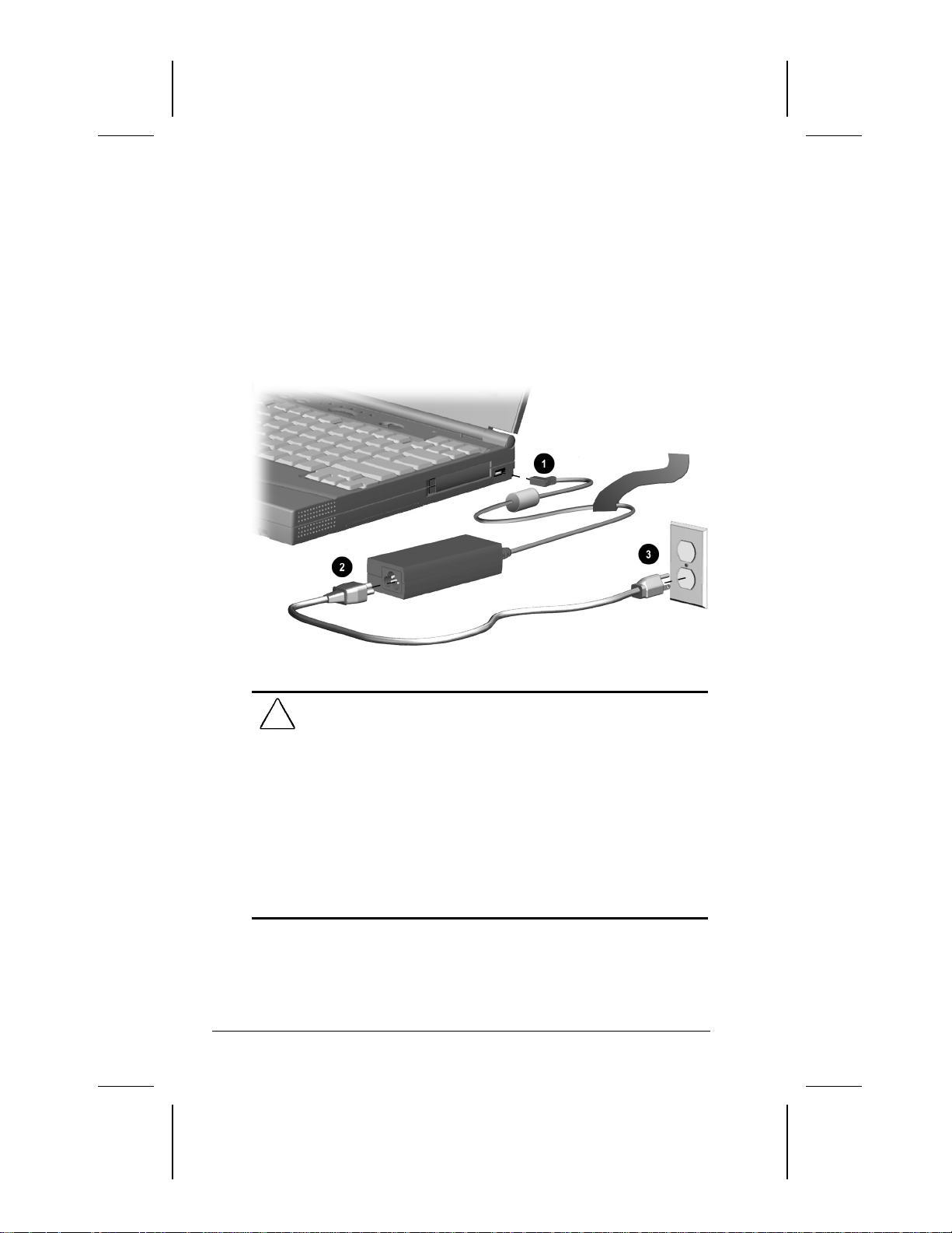
Connecting the Power Cord
1. Place the computer on a flat surface near an electrical outlet.
2. Plug the power cord into the power connector on the right side
of the computer 1.
3. Plug the small end of the power cord to the AC power
connector 2.
4. Plug the large end of the power cord into the electrical
outlet 3.
WARNING:
!
fire, or damage to the equipment:
■
■
■
■
1-2 Getting Started
Writer: Lorise Fazio Saved by: J Abercrombie Saved date: 12/08/98 3:50 PM
To reduce the risk of personal injury, electric shock,
Do not disable the power cord grounding plug. The grounding
plug is an important safety feature.
Plug the equipment into a grounded (earthed) electrical outlet
that is easily accessible at all times.
Disconnect power from the equipment by unplugging the power
cord from the electrical outlet.
Do not place anything on power cords or cables. Arrange them so
that no one may accidentally step on or trip over them. Do not
pull on a cord or cable. When unplugging from the electrical
outlet, grasp the cord by the plug.
Part Number: 310296-002 File name: Ch01.doc
Page 16

Opening the Computer
Slide forward the display release latches on the left and right sides
of the display, then raise the display to a comfortable viewing
angle.
Turning On the Computer
Slide the power switch to turn on the computer. The
power/suspend light indicates the computer is on.
Setting Up the Software
When you begin software setup, online instructions guide you
through the setup process.
IMPORTANT:
After you begin software setup, you must complete
the entire process, which may require up to 20 minutes. Make sure
the computer is plugged in for this process to ensure that software
setup is uninterrupted.
CAUTION:
software drivers are installed:
■
■
To prevent file corruption and ensure the correct
Do not dock the computer in a docking station.
Do not turn off or unplug the computer or remove a drive during
software setup.
Operating the Computer During Setup
To move around the screen while making selections and
■
entering information:
❐
press the
press the cursor (arrow) keys, or
❐
use the pointing device built into the computer keyboard.
❐
To save your selections, press the
■
pointing device buttons below the computer keyboard.
To restore the screen if it is cleared by the screen saver during
■
a period of keyboard and pointing device inactivity, press th
key.
Shift
Tab
key,
key or press one of the
Enter
e
Getting Started 1-3
Writer: Lorise Fazio Saved by: J Abercrombie Saved date: 12/08/98 3:50 PM
Part Number: 310296-002 File name: Ch01.doc
Page 17

For more information about using the pointing device and
pointing device buttons, refer to Chapter 3, “Using the Keyboard
and Pointing Device.”
Choosing a Language
If you are prompted to select your language, choose carefully.
IMPORTANT:
The languages that you do not choose will be deleted
from the computer and cannot be recovered.
Removing the Operating System
A Microsoft Windows operating system is preinstalled on the
computer.
Compaq has enhanced the preinstalled version of this operating
system to provide you with additional software features and
increased computer functionality.
Before deleting the operating system preinstalled on the computer,
please read the following caution:
CAUTION:
■
■
■
Replacing the preinstalled version of this operating system with a
retail version will result in the loss of all enhancements added by
Compaq such as PC Card support and enhanced power
management.
Most preinstalled reference files, such as Help files, are available
only through the Windows interface. If Windows is removed from
the computer, these reference files will become unavailable.
Complete USB support is available only through the Windows
interface. If the operating system preinstalled on the computer is
replaced by an operating system other than this Windows
version, USB support will be decreased.
Restoring Your Operating System and Software
Preinstalled by Compaq
In addition to the preinstalled operating system, Compaq installs
other software to provide additional functionality or
enhancements. If it is necessary to reinstall the operating system
and you do not want to lose these enhancements, it will also be
necessary to reinstall all Compaq software for your computer. Use
the restore software CD that comes with your computer to restore
software on your hard drive.
1-4 Getting Started
Writer: Lorise Fazio Saved by: J Abercrombie Saved date: 12/08/98 3:50 PM
Part Number: 310296-002 File name: Ch01.doc
Page 18

Completing Setup
Compaq recommends that you:
Register the computer.
■
Locate the Compaq online resources, such as the online
■
Reference Guide
Registering the Computer
Be sure to register the computer according to the instructions on
the
Owner Registration Card
Locating Online Resources
and the online
included with the computer.
Safety & Comfort Guide.
For your convenience, all information contained in this
is available online.
Guide
To access the
■
Click Start
❐
Reference Guide
Æ Compaq Information Center Æ
online:
Reference
Reference Guide;
or
Click Start Æ Help Æ Contents;
❐
or
Click the Compaq Information Center icon on the desktop.
❐
To access information on the Internet, go to www.compaq.com.
Getting Started 1-5
Writer: Lorise Fazio Saved by: J Abercrombie Saved date: 12/08/98 3:50 PM
Part Number: 310296-002 File name: Ch01.doc
Page 19
chapter
2
AKING A LOOK AT THE COMPUTER
T
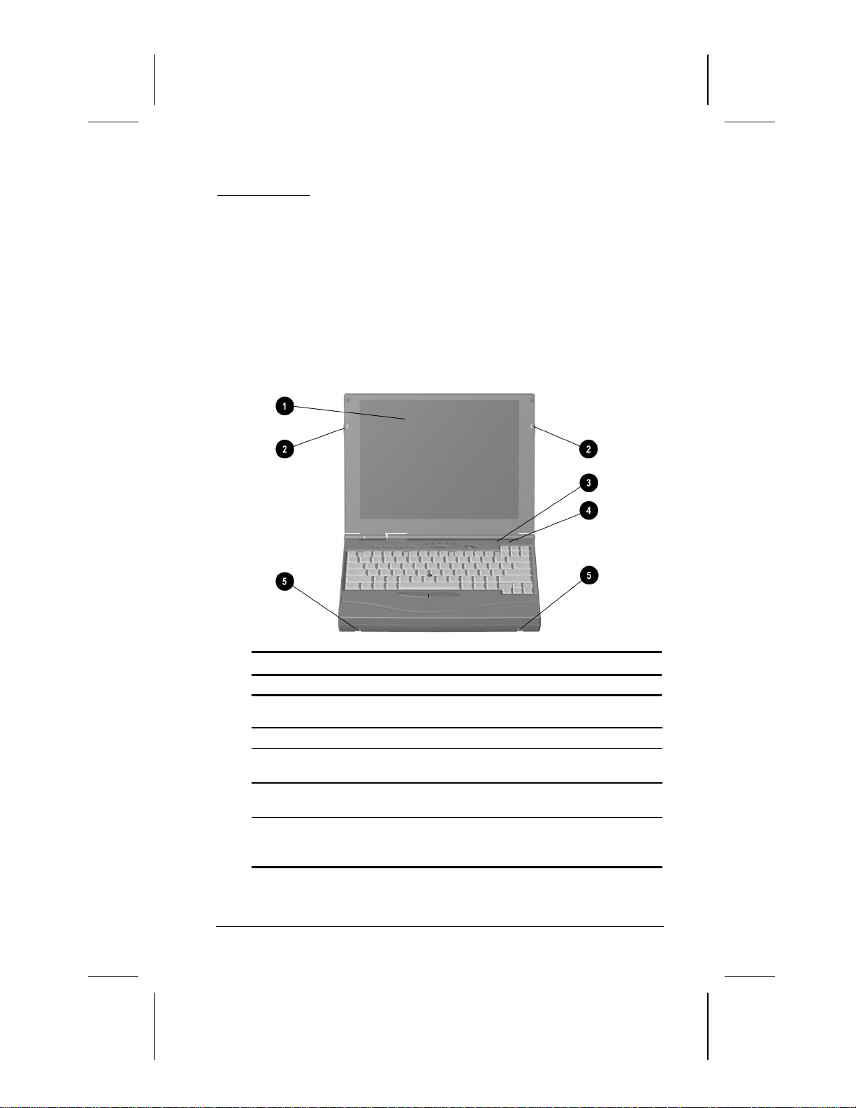
Front Components
Front Components
Component Function
Display The computer screen and the
1
Display latches Opens the computer.
2
Internal microphone Built-in monophonic microphone for
3
Lid switch Blanks the screen if the display is
4
Mobile expansion unit
5
tabs
Writer: Lorise Fazio Saved by: Jessica Gilbert Saved date: 12/04/98 2:37 PM
Pages: 6 Words: 633 Template: c:\msoffice\templates\ref\ref.dot
Part Number: 310296-002 File name: Ch02.doc
hardware in which it is enclosed.
the multimedia sound system.
closed and the computer is still on.
Used to secure the optional Mobile
3500 Expansion Unit (M35EU) to the
computer.
Taking a Look at the Computer 2-1
Page 20
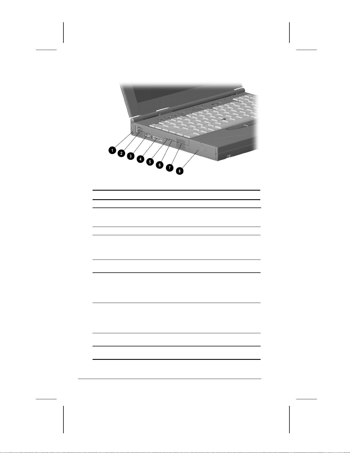
Left Side Components
Left Side Components
Component Function
Cable lock Prevents theft by allowing a cable to
1
Airflow vents Allow airflow to cool the computer.
2
USB connector A connector which allows you to
3
External diskette drive
4
connector
Volume control (up) Increases volume to the built-in
5
Volume control (down) Decreases volume to the built-in
6
Cooling fan Regulates temperature of computer
7
Battery Bay Holds the main battery pack in the
8
be connected to the computer and
secured to a fixed object.
attach Universal Serial Bus (USB)
devices such as a keyboard, mouse,
or camera for video conferencing.
Connects the external diskette drive
to the computer.
speaker, to external speakers, or to
headphones plugged into the
speaker/headphone jack on the
computer.
speaker, to external speakers, or to
headphones plugged into the
speaker/headphone jack on the
computer.
and internal components.
computer.
2-2 Taking a Look at the Computer
Writer: Lorise Fazio Saved by: Jessica Gilbert Saved date: 12/04/98 2:37 PM
Part Number: 310296-002 File name: Ch02.doc
Page 21

Right Side Components
Right Side Components
Component Function
1
Speaker Built-in speaker for high-quality
2
PC Card eject buttons Ejects PC Cards from the PC Card
3
PC Card slots Slots that support Type II or Type III
4
AC power connector Connects to external (AC) power.
sound and a multimedia sound
system.
slots.
PC Cards, such as modem, hard
drive, or network cards. These slots
accept 16-bit PC Cards as well as
CardBus 32-bit PC Cards. The
bottom slot also accepts a Zoomed
Video card.
Taking a Look at the Computer 2-3
Writer: Lorise Fazio Saved by: Jessica Gilbert Saved date: 12/04/98 2:37 PM
Part Number: 310296-002 File name: Ch02.doc
Page 22
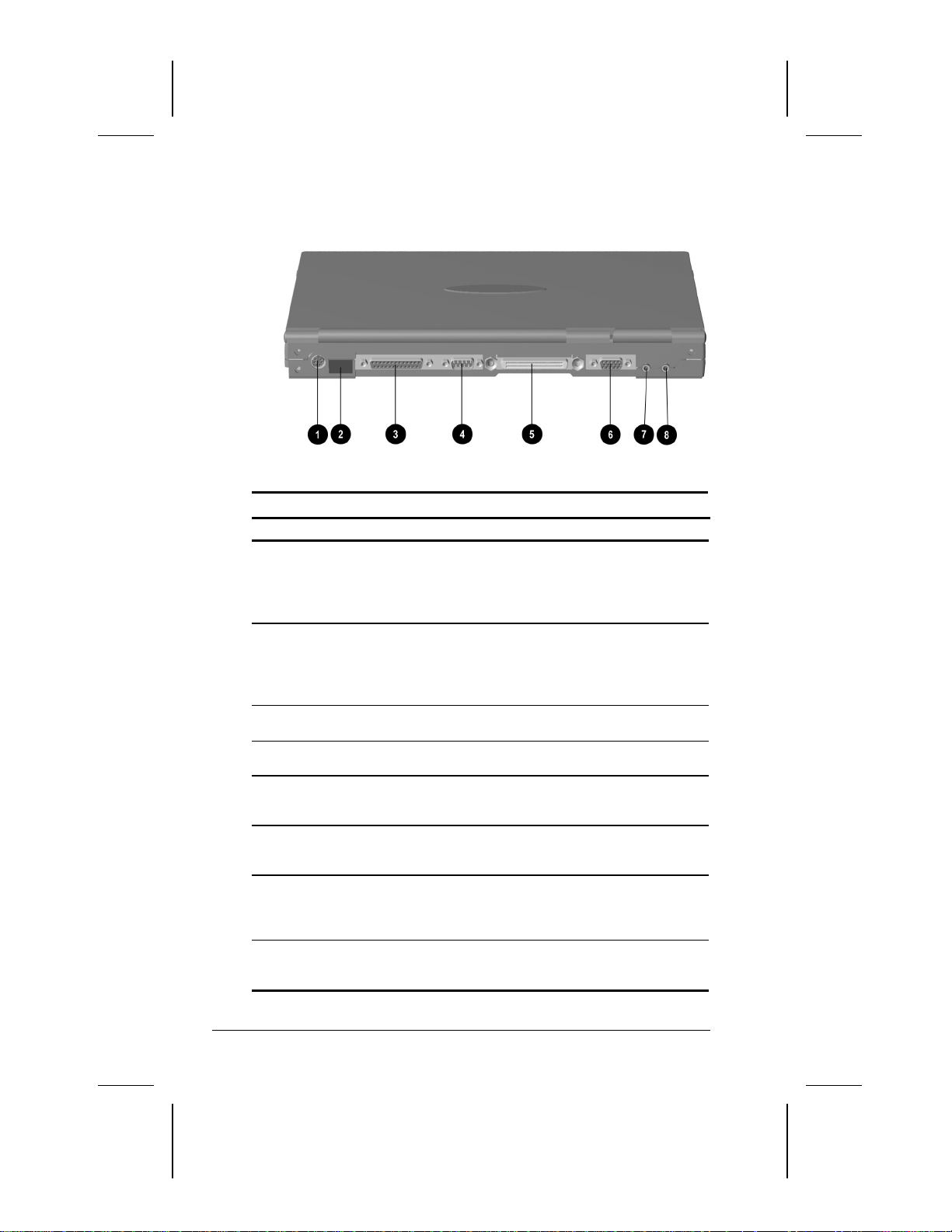
Rear Components
Rear Components
Component Function
1
Keyboard/mouse
connector
2
Infrared port Allows wireless communications
3
Parallel connector Connects an optional parallel device
Serial connector Connects an optional serial device
4
Docking connector A 176-pin expansion bus connector
5
External monitor
6
connector
Microphone line-in jack Connects an external mono
7
Speaker/headphone line-
8
out jack
Connects an optional full-sized
keyboard and/or a PS/2 compatible
mouse. Y connector allows
simultaneous connection of mouse
and keyboard.
between the computer and another
infrared-equipped device using an
infrared light beam. Available on
specific models.
such as a printer.
such as a mouse or printer.
that connects the computer to the
optional convenience base.
Connects an optional external
display, such as an external CRT
monitor.
microphone. The jack requires a 3.5
mm , 2-conductor or 3-conductor
plug.
Connects stereo speakers,
headphone, or headset. The jack
requires a 3.5 mm, 3-conductor plug.
2-4 Taking a Look at the Computer
Writer: Lorise Fazio Saved by: Jessica Gilbert Saved date: 12/04/98 2:37 PM
Part Number: 310296-002 File name: Ch02.doc
Page 23

Bottom Components
Bottom Components
Component Function
Mobile expansion unit
1
tabs
Computer feet Feet on the bottom of the computer
2
Hard drive compartment Provides access to the internal hard
3
Mobile 3500 Expansion
4
Unit connector
Memory compartment Compartment where the memory
5
Used to secure the optional Mobile
3500 Expansion Unit (M35EU) to the
computer.
used to elevate the computer from
the work surface.
drive.
Connects the computer to the
optional Mobile 3500 Expansion Unit
(M35EU).
expansion board is located.
Taking a Look at the Computer 2-5
Writer: Lorise Fazio Saved by: Jessica Gilbert Saved date: 12/04/98 2:37 PM
Part Number: 310296-002 File name: Ch02.doc
Page 24
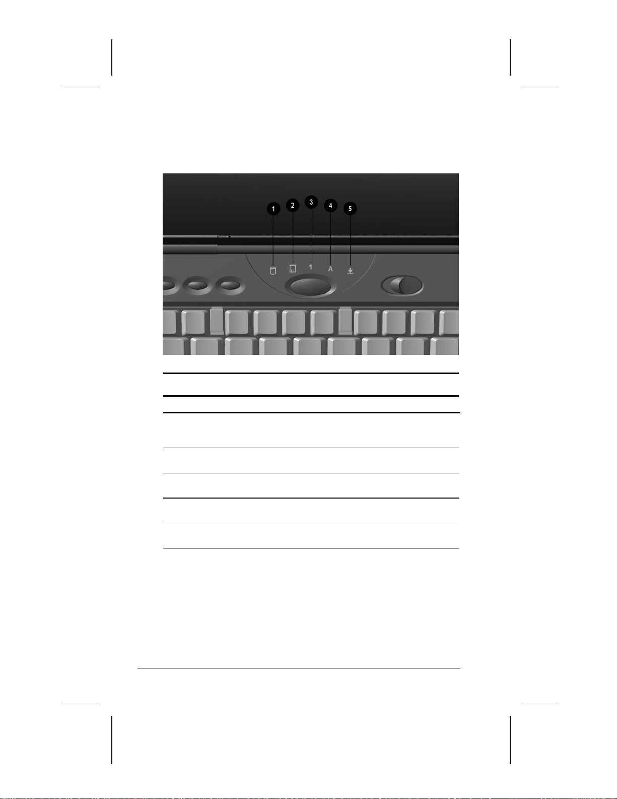
Status Indicator Lights
There are five lights located above the keyboard that indicate system
operations and status. These include:
Status Indicator Lights
Light Function
Hard drive/CD-ROM drive
1
access indicator
Diskette drive access
2
indicator
Num Lock Turns on when the embedded
3
Caps Lock Turns on when the Caps Lock
4
Scroll Lock Turns on when the Scroll Lock key is
5
Turns on when the hard drive,
optional CD-ROM drive, or optional
DVD drive is accessed.
Turns on when the external diskette
drive is accessed.
numeric keypad is active.
function is on.
on.
2-6 Taking a Look at the Computer
Writer: Lorise Fazio Saved by: Jessica Gilbert Saved date: 12/04/98 2:37 PM
Part Number: 310296-002 File name: Ch02.doc
Page 25
chapter
3
SING THE KEYBOARD AND
U
OINTING DEVICE
P
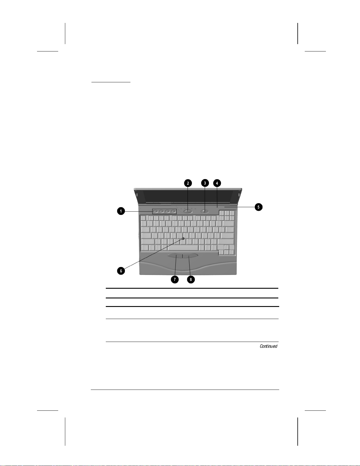
Keyboard Components
Keyboard Components
Component Function
Programmable keys
1
Suspend button
2
Writer: Lorise Fazio Saved by: Johnnie Abercrombie Saved date: 12/18/98 2:51 PM
Pages: 12 Words: 1926 Template: c:\template\ref\ref.dot
Part Number: 310296-002 File name: Ch03.doc
Assign and launch frequently used
applications and documents.
Initiates and exits Suspend. Turns on
the computer if it is off. When used
with the Fn key on the computer, the
Suspend button initiates Hibernation.
Continued
Using the Keyboard and Pointing Device 3-1
Page 26
Keyboard Components
Continued
Component Function
Power switch Slides to turn the computer on or off.
3
Internal microphone Built-in monophonic microphone for
4
Lid switch Blanks the screen if the display is
5
Pointing device Provides mouse functions in all
6
Left mouse button Press the left mouse button to initiate
7
Right mouse button Press the right mouse button to
8
Special Keys
While working in Windows, click
Start, Shut Down to exit the operating
system and turn off the computer.
the multimedia sound system.
closed and the computer is still on.
software that supports a Microsoftcompatible mouse.
an action or confirm a selection.
initiate an action or confirm a
selection.
3-2 Using the Keyboard and Pointing Device
Writer: Lorise Fazio Saved by: Johnnie Abercrombie Saved date: 12/18/98 2:51 PM
Part Number: 310296-002 File name: Ch03.doc
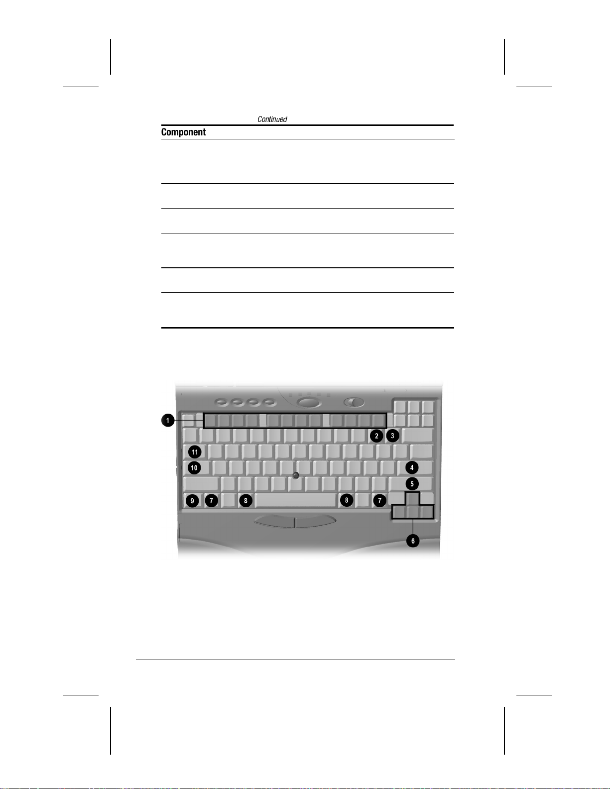
Page 27

Special Keys
Key (s) Function
Function keys (F1
1
through F12)
Delete key Use to remove a command.
2
Num Lock key (Fn key
3
must be pressed)
Enter key Signals the end of input or the end of
4
Shift keys Toggle between uppercase character
5
Arrow keys Move cursor left, right, up, and down.
6
Ctrl keys Used with other keys to enter
7
Alt keys Enter commands when used in
8
Fn key Used in conjunction with function
9
Caps Lock key Shifts the alphabetical characters on
:
Tab key Keyboard function key that moves
;
Enter various commands in a
program, depending on the program
being used.
Shifts to numbers on the embedded
numeric keypad.
a paragraph. To complete a
command you must type or select the
command then press the Enter key.
typing and lowercase character
typing. The Shift key can also be
used in combination with the
Function keys for various commands.
commands.
combination with other keys enters
commands. For example, to switch
between open applications Microsoft
Windows, press Alt+Tab. To close an
application, press Alt+F4.
keys to form hotkey combinations
which simplify special computer
operations. The special hotkey
features are activated by pressing the
Fn key and the function key.
the keyboard into uppercase (capital)
when on.
the cursor to the next tab stop to the
right.
Using the Keyboard and Pointing Device 3-3
Writer: Lorise Fazio Saved by: Johnnie Abercrombie Saved date: 12/18/98 2:51 PM
Part Number: 310296-002 File name: Ch03.doc
Page 28

Using Hotkeys
Hotkeys are keyboard shortcuts that enable you to access
frequently used features no matter what program you’re in.
Hotkey Quick Reference
Function Hotkeys
Moves the Hotkey popup window
location.
Sets the pointing stick
characteristics. Allows you to
adjust settings for touch sensitivity
and toggle between twodimensional and three-dimensional
capability.
Switches displays—toggles
between computer display,
external monitor display, and both
displays at the same time.
Adjusts Speaker volume—controls
system warning beeps. To
increase volume, press Fn+F5,
then the right arrow key. To
decrease volume, press Fn+F5,
then the left arrow key.
Sets QuickLock/QuickBlank—
disables the keyboard and mouse,
and clears the display. See
Chapter 13 for more information on
Quick Controls.
Sets Battery Conservation—
adjusts the level of battery power
used by the computer. (Windows
95 and Windows NT only.) See
Chapter 5 for more information on
power conservation.
Displays the battery gauge—
shows the amount of power
remaining in all system batteries.
For more information on using the
battery gauge, see Chapter 4.
Fn+F1 Fn+F1
Fn+F2 Fn+F2
Fn+F4 Fn+F4
Fn+F5 Fn+F5
Fn+F6 Enter password
Fn+F7 Fn+F7
Fn+F8 Fn+F8
Return to
Original State
Continued
3-4 Using the Keyboard and Pointing Device
Writer: Lorise Fazio Saved by: Johnnie Abercrombie Saved date: 12/18/98 2:51 PM
Part Number: 310296-002 File name: Ch03.doc
Page 29

Hotkey Quick Reference
Continued
Function Hotkeys
Adjusts display contrast—controls
the image on the display. Not
applicable on active matrix
displays.
Adjusts display brightness—
controls the light intensity of the
display.
Enables and disables the
embedded numeric keypad. See
“Embedded Numeric Keypad”, in
this chapter.
Initiates Hibernation (Windows 95
and Windows NT only). See
Chapter 5 for more information on
using Hibernation.
Initiates Text-stretch function—
stretches the image so that more
of the screen is filled (functions
optimally on display panels less
than 13 inches).
Fn+F9 Fn+F9
Fn+F10 Fn+F10
Fn+Num Lk Fn+Num Lk
Fn+Suspend Suspend
Fn + T Fn + T
Return to
Original State
IMPORTANT:
Popup windows associated with the hotkeys display
correctly only from within applications that support the popup
video mode. If a popup does not display correctly, exit the
application and press the hotkeys again to invoke the popup
window.
Using the Keyboard and Pointing Device 3-5
Writer: Lorise Fazio Saved by: Johnnie Abercrombie Saved date: 12/18/98 2:51 PM
Part Number: 310296-002 File name: Ch03.doc
Page 30
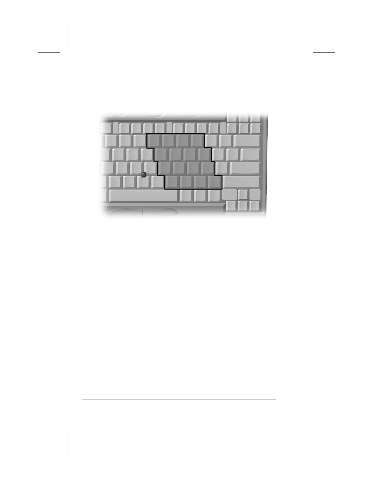
Embedded Numeric Keypad
The embedded numeric keypad is a section of the computer
keyboard that converts to a numeric keypad when the number lock
function is enabled.
Press the
■
Fn+Num Lk
Enable the embedded numeric keypad (Num Lk light
hotkeys to:
turns on).
Disable the embedded numeric keypad (Num Lk light
■
turns off).
With the number lock function on (enabled):
Press Fn to type lowercase letters.
■
Press
■
3-6 Using the Keyboard and Pointing Device
Fn+Shift
to type uppercase letters.
Writer: Lorise Fazio Saved by: Johnnie Abercrombie Saved date: 12/18/98 2:51 PM
Part Number: 310296-002 File name: Ch03.doc
Page 31

User Programmable Keys
You can set the four user-programmable keys to bring up a
document or emulate the Microsoft Windows and Application
Logo Keys.
By assigning schemes to the programmable keys, you can create
multiple sets of key assignments tailored to your own needs or to
accommodate more than one user.
To assign the programmable keys and create schemes, see
"Assigning the User-Programmable Keys" in this chapter.
Using the Keyboard and Pointing Device 3-7
Writer: Lorise Fazio Saved by: Johnnie Abercrombie Saved date: 12/18/98 2:51 PM
Part Number: 310296-002 File name: Ch03.doc
Page 32

Assigning the User-Programmable Keys
To assign or reassign a programmable key:
1. Access the Programmable Keys utility by clicking Start Æ
Settings Æ Control Panel Æ Keyboard icon Æ Programmable
Keys.
2. Select the current scheme programmable key you wish to
assign or reassign by clicking its button in the Key
Assignments group box.
NOTE:
To access a larger number of programs, place a check
in the Show Advanced Options checkbox. This changes the
Assign button to the Browse button. By clicking the Browse
button, you can access all applications on your computer. To
emulate one of the Microsoft Windows and Application Logo
Keys, select the appropriate file from the PROGRAM
FILES\COMPAQ\PROGRAMMABLE KEYS\DEFAULT
directory.
3. Click the Assign button. A dialog box appears showing a list
of programs or documents from the Programs menu.
4. Highlight the desired application and click OK. The icon and
program name you select appear beside the programmable
key's radio button.
5. Click OK to exit the utility. When you press the
programmable key you have just assigned, your application
and/or document appears on screen.
3-8 Using the Keyboard and Pointing Device
Writer: Lorise Fazio Saved by: Johnnie Abercrombie Saved date: 12/18/98 2:51 PM
Part Number: 310296-002 File name: Ch03.doc
Page 33

Unassigning the User-Programmable Keys
To remove a programmable key assignment:
1. Access the Programmable Keys utility by clicking Start
Settings Æ Control Panel Æ Keyboard icon Æ Programmable
Keys.
2. Select the programmable key you wish to unassign by clicking
the appropriate radio button in the Key Assignments group
box.
To unassign keys in other than the current scheme, place
NOTE:
a check in the Show Advanced Options checkbox and select a
different scheme. If you have never created a scheme, the
Default scheme will be the only choice.
3. Click the Assign button, then select Unassigned from the list.
The icon and program name previously assigned to the key
will be removed.
When the Show Advanced Options box is checked, you
NOTE:
can unassign a programmable key by clicking the Browse
button and selecting the file 'Unassigned' from the
PROGRAM FILES\COMPAQ\PROGRAMMABLE
KEYS\DEFAULT directory.
4. Click OK to exit the utility.
Adding Schemes
To add a new scheme:
Æ
1. Access the Programmable Keys utility by clicking Start
Settings Æ Control Panel Æ Keyboard icon Æ Programmable
Keys.
2. Ensure that the Show Advanced Options checkbox is checked.
3. Click the Add button.
4. Type a name for your new scheme in the popup dialog box
that appears.
5. Make your programmable key assignments.
6. Click OK to exit the utility.
Using the Keyboard and Pointing Device 3-9
Writer: Lorise Fazio Saved by: Johnnie Abercrombie Saved date: 12/18/98 2:51 PM
Part Number: 310296-002 File name: Ch03.doc
Æ
Page 34

Removing Schemes
To remove a scheme:
1. Access the Programmable Keys utility by clicking Start Æ
Settings Æ Control Panel Æ Keyboard icon Æ Programmable
Keys.
2. Ensure that the Show Advanced Options checkbox is checked.
3. Select the scheme in the Scheme box that you want to delete.
To view a different scheme, select a scheme from the dropdown list.
NOTE:
The Default scheme is not removable.
4. Click the Remove button.
5. Click OK to exit the utility.
Showing the Key Assignments in the System Tray
One convenient way to see your user-programmable key
assignments is to view them in a popup window that you activate
from an icon in the system tray. To enable the icon:
1. Access the Programmable Keys utility by clicking Start Æ
Settings Æ Control Panel Æ Keyboard icon Æ Programmable
Keys.
2. Check mark the Show Key Assignments in the System Tray
checkbox.
3. Click OK to exit the utility.
An icon appears in the system tray. To view the popup window,
click the icon.
NOTE:
The icon remains in the system tray until you disable it by
unchecking the Show key assignments in the System Tray
checkbox or by right-clicking the icon and choosing Exit from the
menu.
3-10 Using the Keyboard and Pointing Device
Writer: Lorise Fazio Saved by: Johnnie Abercrombie Saved date: 12/18/98 2:51 PM
Part Number: 310296-002 File name: Ch03.doc
Page 35

Using the Pointing Stick
The EasyPoint IV pointing stick performs the same basic
operation as a mouse but does not move; it senses finger
movement and pressure. It provides point-and-click (threedimensional) functions as well as standard (two-dimensional)
pointing stick features. You can easily modify the EasyPoint IV
settings for the way you work. EasyPoint IV is compatible with
Microsoft Windows 3.1, Windows 95, Windows 98, and Windows
NT 4.0 operating systems.
Using Two-Dimensional Features
In the two-dimensional setting, the pointing stick and the left and
right buttons on the wrist rest are used together to function as a
standard two button mouse. The pointing stick moves the cursor.
The buttons provide primary and secondary click functions.
1. Place your index finger on top of the pointing stick 1.
2. Press in the direction you want the cursor to move on the
screen.
3. Click the left mouse button 2 or right mouse button 3 with
your thumb.
Using the Keyboard and Pointing Device 3-11
Writer: Lorise Fazio Saved by: Johnnie Abercrombie Saved date: 12/18/98 2:51 PM
Part Number: 310296-002 File name: Ch03.doc
Page 36

Using Three-Dimensional Features
The three-dimensional setting provides the features of the twodimensional setting in addition to the following features when you
press down on the pointing stick:
Press-to-select, single-click, and double-click selection and
■
activation—tap the pointing stick, which generates the same
event as clicking the left click button.
Press-and-drag—press and hold the pointing stick down while
■
moving the cursor.
Customizing the Settings
The pointing stick control panel allows you to toggle between the
two-dimensional and three-dimensional settings and to adjust the
pointing stick touch sensitivity. Press Fn+F2 to activate the
pointing stick control panel.
To toggle between two-dimensional and three-dimensional
functions:
1. Activate the pointing stick control panel.
2. Press the up or down arrow key. The control panel will
indicated whether the two-dimensional or three-dimensional
setting is currently active.
To adjust the sensitivity of the pointing stick:
1. Activate the pointing stick control panel.
2. Press the right arrow key to increase sensitivity for
faster cursor movement
■
easier tap responses (only with three-dimensional enabled)
■
Press the left arrow key to decrease sensitivity for
slower cursor movement
■
firmer tap responses (only with three-dimensional enabled)
■
Replacing the Pointing Device Rubber Cap
Your computer comes with replaceable pointing stick caps. To
replace the pointing stick cap:
1. Shut down the computer or exit all applications.
2. Gently pull off the rubber cap.
NOTE:
If the plastic cap underneath the rubber cap comes off,
gently push it back on.
3. Gently push on the new rubber cap.
Customizing the Pointing Stick Controls
Access the Mouse utility by clicking Start Æ Settings Æ Control
Panel Æ double-click Mouse Æ General tab Æ Options. Then you
may:
Customize the way the pointing stick controls the pointer.
■
Control the pointer motion.
■
3-12 Using the Keyboard and Pointing Device
Writer: Lorise Fazio Saved by: Johnnie Abercrombie Saved date: 12/18/98 2:51 PM
Part Number: 310296-002 File name: Ch03.doc
Page 37

chapter
4
SING BATTERY PACKS
U
Learning About Batteries
The computer accommodates one rechargeable battery pack.
With the computer turned off, the battery pack will recharge in
less than two hours. With the computer turned on, the battery pack
will recharge in less than five hours.
To avoid loss of data, save data, then either turn off the computer
or initiate Hibernation or Suspend before removing the battery.
WARNING:
!
There is a risk of fire and burns if the battery pack is not handled
properly. Do not disassemble, crush, puncture, short external
contacts, or dispose of in fire or water. Do not expose to
temperatures higher than 60qC. Replace only with the Compaq
spare designated for this product.
WARNING:
!
disposed of with general household waste. In order to forward them
to recycling or proper disposal, please use the public collection
system or return them to Compaq, your authorized Compaq
Partners, or other agents.
Your computer contains a lithium Ion battery pack.
Batteries/battery packs and accumulators should not be
Using a New Battery Pack
IMPORTANT:
is used for the first time. The battery pack will work partially
charged, but the battery gauge will not show an accurate charge
until the battery pack receives its first full charge.
A new battery pack should be fully charged before it
Using Battery Packs 4-1
Writer: Lorise Fazio Saved by: J Abercrombie Saved date: 12/08/98 4:03 PM
Pages: 12 Words: 2227 Template: c:\template\ref\ref.dot
Part Number: 310296-002 File name: Ch04.doc
Page 38

You can charge the battery pack in the computer's Battery Bay
while connected to an external power source or while the
computer is docked in the convenience base. You can also charge
an extra battery pack using the optional battery charger.
The battery pack has a battery gauge on its top. Press the button
on the top of the battery pack to see how much charge remains. If
all five lights on the side of the battery pack light up when the
button is pressed, the battery is fully charged.
Charging Battery Packs
To charge the battery pack, follow these steps:
1. With the battery pack in the Battery Bay, connect the power
cord to the computer and plug it into an electrical outlet.
2. Turn on the computer if you want to use it while the battery
pack is charging.
NOTE:
The battery charge light is the right light on the front of
the computer. The light illuminates when a battery pack is
charging. The light turns off when fully charged and blinks in
a low-battery condition.
It takes up to two hours for the battery pack to fully charge when
the computer is turned off. It takes up to five hours to charge the
battery pack when the computer is in use. When the battery charge
light turns off, the battery pack is fully charged.
4-2 Using Battery Packs
Writer: Lorise Fazio Saved by: J Abercrombie Saved date: 12/08/98 4:03 PM
Part Number: 310296-002 File name: Ch04.doc
Page 39

Using the Battery Gauge
Press the
hotkeys to show the status of the battery pack.
Fn+F8
The box indicates the status of the installed battery pack.
Battery pack 1 is the battery in the computer Battery Bay.
The percentage of battery charge remaining for the battery pack is
shown at the bottom of the popup. If the battery pack is charging,
a lightning bolt symbol appears to the right of the box. If AC
power is connected, the power connector is shown.
NOTE:
If you do not press any key for five to seven seconds, the
battery gauge popup will display the average remaining capacity
(percent of charge remaining).
Ensuring Battery Gauge Accuracy
The built-in battery gauge, which displays the amount of charge
remaining, is precalibrated for accuracy. To ensure continued
battery gauge accuracy and to maximize battery operating time:
Fully charge the battery pack before you use it for the first
■
time.
Allow the battery pack to completely charge before removing
■
external power from the computer, convenience base, or
battery charger.
If the battery has been out of the computer for two weeks or
■
more, fully recharge the battery pack before using it.
Approximately every 60 days, allow the battery to completely
■
discharge to the low battery condition through normal use
before recharging it.
Using Battery Packs 4-3
Writer: Lorise Fazio Saved by: J Abercrombie Saved date: 12/08/98 4:03 PM
Part Number: 310296-002 File name: Ch04.doc
Page 40

The various battery gauges available on your system should
NOTE:
be regarded as an approximate indication of remaining battery life.
Use the battery until the first warning is received, even if the
gauge indicates "no power."
Identifying a Low Battery Condition
When a low battery condition is reached, the computer beeps
twice approximately once every five minutes, and the battery
charge light blinks once per second. When a critical low-battery
condition is reached, the computer beeps four times every five
seconds, and the battery light blinks twice per second.
CAUTION:
battery charge remains. Take immediate action to resolve the
condition.
When you are alerted to a low battery condition, very little
When a low battery condition is reached, save your files and
initiate Suspend. You have approximately 5-10 minutes to resolve
the low battery condition before the computer enters the critical
low battery condition.
When a critical low battery condition occurs and Hibernation is
enabled, the system initiates Hibernation.
CAUTION:
Hibernation when a critical low battery condition is reached. If
Hibernation is disabled, the computer initiates Suspend until the
battery pack fully discharges. When this occurs, all unsaved
data is lost.
If Hibernation is disabled, the computer cannot initiate
4-4 Using Battery Packs
Writer: Lorise Fazio Saved by: J Abercrombie Saved date: 12/08/98 4:03 PM
Part Number: 310296-002 File name: Ch04.doc
Page 41

Resolving a Low Battery Condition by Connecting
the Power Cord
To connect the power cord to the computer:
1. Place the computer on a flat surface near an electrical outlet.
2. Plug the power cord into the power connector on the right side
of the computer 1.
3. Plug the small end of the power cord to the AC power
connector 2.
4. Plug the large end of the power cord into the electrical
outlet 3.
Using Battery Packs 4-5
Writer: Lorise Fazio Saved by: J Abercrombie Saved date: 12/08/98 4:03 PM
Part Number: 310296-002 File name: Ch04.doc
Page 42

Resolving a Low Battery Condition by Connecting the
Automobile/Aircraft Adapter
IMPORTANT:
When using the Automobile/Aircraft Adapter in a
vehicle, leaving the computer on for an extended period of time
when the vehicle's engine is turned off may drain the vehicle's
battery.
To connect the Automobile/Aircraft Adapter to the computer:
1. Turn on the vehicle's engine.
2. Connect the computer connector end of the AC Adapter cable
to the AC power connector 1 on the right side of the
computer.
3. Insert one end of the AC Adapter power cable into the
Automobile/Aircraft Adapter and insert the other end into the
AC Adapter.
4. Insert the free end of the Automobile/Aircraft Adapter power
cable into the cigarette lighter receptacle 2.
4-6 Using Battery Packs
Writer: Lorise Fazio Saved by: J Abercrombie Saved date: 12/08/98 4:03 PM
Part Number: 310296-002 File name: Ch04.doc
Page 43

Resolving a Low-Battery Condition with a
Charged Battery Pack
CAUTION:
is on, you can prevent loss of information by initiating Hibernation
before removing the battery pack.
If you are removing the battery pack while the computer
1. Stop working and save your work immediately.
2. Either press the suspend button to initiate Suspend or press the
Fn+Suspend
buttons to initiate Hibernation.
3. Remove the discharged battery pack.
4. Insert a fully charged battery pack.
5. Exit Hibernation.
Resolving a Low Battery Condition When
No Power Source Is Available
To resolve a low battery condition when no power source is
available, do one of the following:
Initiate Suspend if you have a spare fully charged battery
■
pack. After you have inserted the spare battery pack, press the
Suspend button to exit Suspend. All information returns to the
screen at the point where Suspend was initiated. Power
continues to be used, but at a slower rate. If the battery pack
fully discharges while the computer is in Suspend, all unsaved
data will be lost.
Initiate Hibernation until a power source is available. This
■
automatically saves all current information in memory to the
hard disk and turns off the computer. When power is available
and the computer is turned on, all information returns to the
screen at the point where Hibernation was initiated.
Save your information, then turn off the computer until a
■
power source is available.
Using Battery Packs 4-7
Writer: Lorise Fazio Saved by: J Abercrombie Saved date: 12/08/98 4:03 PM
Part Number: 310296-002 File name: Ch04.doc
Page 44

Inserting and Removing Battery Packs
Removing the Battery Pack from the Battery Bay
CAUTION:
to external power before removing the battery.
Initiate Suspend or Hibernation, or connect the computer
To remove the battery pack from the Battery Bay:
1. Open the computer display 1.
The closed display provides an added lock to keep the
NOTE:
battery pack secure during transport. The display must be
opened before removing the battery pack from the Battery
Bay.
2. Push up on the ridges on the battery pack cover 2.
3. Remove the battery pack from the Battery Bay 3.
4-8 Using Battery Packs
Writer: Lorise Fazio Saved by: J Abercrombie Saved date: 12/08/98 4:03 PM
Part Number: 310296-002 File name: Ch04.doc
Page 45

Inserting the Battery Pack into the Battery Bay
CAUTION:
computer to external power before removing the battery.
Initiate Suspend or Hibernation, or connect the
To insert the battery pack into the Battery Bay:
1. Open the computer display 1.
The closed display provides an added lock to keep the
NOTE:
battery pack secure during transport. The display must be
opened before inserting the battery pack into the Battery Bay.
2. Push the battery pack into the Battery Bay until it is firmly
seated 2.
3. Push down on the ridges on the battery pack cover to close the
cover 3.
Using Battery Packs 4-9
Writer: Lorise Fazio Saved by: J Abercrombie Saved date: 12/08/98 4:03 PM
Part Number: 310296-002 File name: Ch04.doc
Page 46

Storing Battery Packs
When storing the computer for more than two weeks, remove the
battery packs and store them separately to reduce the discharge
rate and increase battery life.
The battery pack self-discharges even when it is not being used.
The rate of self-discharge is affected by temperature. To prolong
battery charge, store the battery in a cool, dry place. High
temperatures cause the battery pack to lose its charge more
quickly, thus reducing battery life.
The recommended storage temperature range is from 32qF to
104qF (0qC to 40qC). However, a battery can be stored at 32qF to
140qF (0qC to 60qC) for up to 30 days.
CAUTION:
high temperatures for extended periods of time.
To prevent damage to a battery pack, do not expose it to
Maximizing Battery Pack Life
Battery pack operating time varies depending on the system
components, options, and applications used. You can increase
battery operating time by as much as 50 percent by controlling the
energy used by the computer and the energy stored in the battery
pack.
NOTE:
T
he display, processor, and drive components use the
majority of battery power.
To maximize battery pack life, use the following guidelines:
Select the High level of power management (not available
■
under Windows 98). See Chapter 5 for more information on
power management.
Initiate Suspend or Hibernation, or turn the computer off when
■
you are not using it.
Reduce the display brightness and select a shorter screen save
■
timeout.
Keep a battery pack in the computer when you are using the
■
computer with external power.
Disconnect external equipment that does not have its own
■
power source. (External equipment connected to the computer
drains the battery pack.)
4-10 Using Battery Packs
Writer: Lorise Fazio Saved by: J Abercrombie Saved date: 12/08/98 4:03 PM
Part Number: 310296-002 File name: Ch04.doc
Page 47

Exit modem programs when you are not using them.
■
Remove a PC Card when you are not using it.
■
When storing the computer for more than two weeks, remove
■
battery pack(s) and store them separately to reduce the
discharge rate and increase battery life.
Store the battery pack in a cool, dry place when it is not in use.
■
High temperatures cause a battery pack to lose its charge more
quickly and reduce battery pack life. For more information on
storing battery packs, see "Storing Battery Packs" in this
chapter.
Format diskettes while using external power when possible.
■
(Formatting diskettes increases the drain on a battery pack.)
Recycling Used Battery Packs
To find out if the battery pack recycling program is available in
your geographical location, check the worldwide telephone
numbers. If a number for recycling is not listed for your area,
contact your Compaq authorized dealer, reseller, or service
provider.
System Beeps
Beeps with a Blinking Battery Charge Light
When the computer beeps while the battery charge light is
blinking, the computer has entered a low battery condition.
CAUTION:
little battery charge remains. Save your information and take
immediate action to resolve the low battery condition.
If you prefer not to be alerted with system beeps, see “Turning
Beeps On or Off” in this chapter.
When you are alerted of a low battery condition, very
Using Battery Packs 4-11
Writer: Lorise Fazio Saved by: J Abercrombie Saved date: 12/08/98 4:03 PM
Part Number: 310296-002 File name: Ch04.doc
Page 48

Beeps with a Blinking Power/Suspend Light
When the computer beeps while the power/suspend light is
blinking, the computer has initiated Suspend. See Chapter 5 for
more information on using Suspend.
When the computer is in Suspend and a low battery
NOTE:
condition occurs, pressing the power button or suspend button will
NOT exit Suspend. Connect the computer to AC power until a
fully charged battery is available.
If you prefer not to be alerted with system beeps, see “Turning
Beeps On or Off” in this chapter.
Turning Beeps On or Off
Based on the type of beeps you want to turn on or off, do one of
the following:
To enable or disable PC Card beeps, click Control Panel
■
double-click PC Card iconÆGlobal Settings tab, then click to
check or uncheck the Disable PC Card Sound Effects box.
To toggle all system beeps on or off, use the Computer Setup
■
Utility. The following beeps are affected (see Chapter 15 for
more information on using Computer Setup):
Low battery warning beeps
❏
Æ
Power-On Self-Test (POST) beeps
❏
Suspend beeps
❏
To disable only low battery warning beeps, click Start Æ
■
Settings Æ Control Panel Æ double-click Power Æ Power
Properties Æ Conservation Settings tab. Then click the
Warning Beeps Off button.
NOTE:
Application-specific beeps must be controlled through the
application software.
4-12 Using Battery Packs
Writer: Lorise Fazio Saved by: J Abercrombie Saved date: 12/08/98 4:03 PM
Part Number: 310296-002 File name: Ch04.doc
Page 49

chapter
5
OMPUTER POWER AND POWER
C
ANAGEMENT
M
IMPORTANT:
conservation features described in this chapter will be disabled.
For more information on power conservation under Windows 98,
refer to the section "Using ACPI Power Control" in this chapter.
If you are running Windows 98, several power
Leaving On the Computer
When the computer is left on for extended periods, such as
overnight, you may want to initiate Suspend to conserve power.
The computer should be left in Suspend when it will be
unattended and operating only on battery power. With a fully
charged battery pack, the computer can be left in Suspend for up
to several days, depending on your hardware configuration.
Turning Off the Computer
CAUTION:
and turn off the computer. Failure to properly exit can result in lost
data or corrupted files.
If you are working in DOS or if you experience a severe system
crash, you can use the power switch to turn off the computer, or
press
locked up.
In Windows, use Shut Down to exit the operating system
Ctrl+ALT+Delete
if either the keyboard or the system is
If you plan to store the computer for an extended period, such as
two weeks, you should turn off the computer and remove the
battery pack. This reduces the battery pack's discharge rate and
extends its life.
Computer Power and Power Management 5-1
Writer: Lorise Fazio Saved by: Johnnie Abercrombie Saved date: 12/08/98 4:05 PM
Pages: 12 Words: 2410 Template: c:\template\ref\ref.dot
Part Number: 310296-002 File name: Ch05.doc
Page 50

If you use the computer frequently and want "instant-on"
convenience, you do not have to turn off the computer. Simply
initiate Suspend when the computer is not in use. With a fully
charged battery pack, the computer can be left in Suspend up to
several days, depending on your hardware configuration.
If you want to charge a battery pack while you are not using the
computer, connect the computer to external power and turn it off.
Although the battery pack will charge whether the computer is
turned on or off, it takes more than twice as long to charge it with
the computer on.
When external power is not available and battery power is low,
initiate Hibernation by pressing
Fn+Suspend
buttons, or complete
the following steps:
1. Save your information.
2. Exit your applications.
3. Turn off the computer using Windows Shut Down (if you are
in Windows) or by using the power switch (if you are in DOS)
until external power or a fully charged battery pack is
available.
Restarting the Computer
There are several methods to restart the computer, depending on
the power state:
From Hibernation Slide the power switch.
From Suspend Press the suspend button.
From Windows Click Shut Down from the Start menu,
then click Restart the Computer.
5-2 Computer Power and Power Management
Writer: Lorise Fazio Saved by: Johnnie Abercrombie Saved date: 12/08/98 4:05 PM
Part Number: 310296-002 File name: Ch05.doc
Page 51

Disconnecting the Computer
from External Power
When the computer does not contain a charged battery pack, save
your work and turn off the computer before disconnecting it from
external power.
When a charged battery pack is in the computer, you do not need
to turn off the computer before disconnecting it from external
power. The computer automatically switches to battery power.
IMPORTANT:
external power for an extended period of time, remove the battery
pack(s). This reduces the discharge rate and extends battery life.
If the computer will be unused and disconnected from
Managing Power
If you are running Windows 95 or later, the computer comes
equipped with a collection of power management features that
allow you to extend battery operating time or conserve AC power.
You can use power management to monitor most of the computer
components, such as the hard drive, processor, and display. When
these components are inactive for specified periods of time (called
timeouts), you can use power management settings to shut them
down temporarily. This will conserve battery or AC power.
Most power management settings are located under Power
Properties (Click Start Æ Control Panel Æ double-click Power Æ
Power Properties). These setting options allow you to configure
the way your system uses battery and AC power.
Computer Power and Power Management 5-3
Writer: Lorise Fazio Saved by: Johnnie Abercrombie Saved date: 12/08/98 4:05 PM
Part Number: 310296-002 File name: Ch05.doc
Page 52

Use the following table to view or change power management
settings.
If you are running Windows NT, the power management
NOTE:
settings may be viewed or changed under Start Æ Control Panel
double-click Power Æ Power Properties.
Æ
Click This Tab in
If You Want To:
Show Suspend on the Start
menu
Show battery gauge on the
taskbar
Set battery conservation
levels; enable/disable
warning beeps; set timeouts
Select Hibernation settings;
set Hibernation timeouts
Set timeouts for drives when
using battery power or AC
power
Turn off power to the PC Card
slots
Set date and time to exit
suspend; enable/disable
Resume Timer
Display the status of installed
batteries
Power Properties:
Power + Advanced button
Power (Windows 95 only)
Battery Conservation Settings
Hibernation
Disk Drives (Windows 95 only)
PC Card Modems (Windows 95
only)
Resume Timer
Battery Status
5-4 Computer Power and Power Management
Writer: Lorise Fazio Saved by: Johnnie Abercrombie Saved date: 12/08/98 4:05 PM
Part Number: 310296-002 File name: Ch05.doc
Page 53

Setting the Battery Conservation Level
If you're running Windows 95 or later, you can set battery
conservation to one of four levels:
■
Medium—The default setting. Balances system performance
and battery operating time.
■
High—Provides maximum battery conservation. Select this
level if you need more battery life and do not mind shorter
timeouts and a dimmer display.
■
None (Drain)—Results in maximum battery drain because
battery conservation is turned off. Recommended only for
discharging the battery pack.
CAUTION:
the computer is in Drain mode. Before selecting this
conservation level, be sure the Hibernation feature has not been
disabled.
■
Custom–Lets you set the timeouts so that the computer works
Hibernation does not automatically initiate while
efficiently in your environment. The default setting (Medium)
is used here until you set your own.
You can set the battery conservation level one of two ways:
Setting the Battery Conservation Level with Hotkeys: Choose
■
a preset level of battery conservation by pressing
Fn+F7
you select None (Drain), it remains in effect until you change
it.
Using Power Properties: Change the default levels of battery
■
conservation through the Battery Conservation Settings tab in
Power Properties (click Start Æ Control Panel Æ double-click
Power Æ Power Properties). Choose a preset level or
customize your own level. The level you set remains in effect
until you change it.
. If
Computer Power and Power Management 5-5
Writer: Lorise Fazio Saved by: Johnnie Abercrombie Saved date: 12/08/98 4:05 PM
Part Number: 310296-002 File name: Ch05.doc
Page 54

Using ACPI Power Control
Under Windows 98, ACPI is a system-wide approach to system
and device power control, as well as thermal management. ACPI
enables the operating system to respond to events and manage
power for the entire system and its devices. It makes the computer
more accessible by reducing boot time and allowing the computer
to wake up automatically. ACPI also incorporates power
management that reduces power consumption of the computer by
turning off the microprocessor and other components when
applications are idle or between keystrokes.
For more information on ACPI functions, consult your Microsoft
Windows 98 reference guide.
Using Hibernation
Hibernation is a safeguard feature that saves your information
when the computer reaches a low battery condition while it is left
unattended. When your computer hibernates, all the information in
system memory is saved to the hard disk and the power to the
computer is turned off. When you turn on the computer, your
information returns to the screen at the point where Hibernation
initiated. Hibernation behaves like a bookmark, and none of your
information is lost.
When Hibernation is initiated, it creates a file on the hard drive at
least equal in size to the amount of total random access memory
(RAM). If there is not enough space on the hard disk to store the
information, an insufficient disk space message is displayed.
Hibernation will automatically initiate as long as it is not disabled
(turned off) through the software. If you disable Hibernation and
the computer reaches a low battery condition, your unsaved
information will be lost.
CAUTION:
use the computer, the system may not hibernate and your unsaved
information will be lost.
5-6 Computer Power and Power Management
If a low battery condition occurs and you continue to
Writer: Lorise Fazio Saved by: Johnnie Abercrombie Saved date: 12/08/98 4:05 PM
Part Number: 310296-002 File name: Ch05.doc
Page 55

Enabling Hibernation
If you have disabled Hibernation, you can enable it again through
the Hibernation tab in Power Properties (click Start Æ Control
Panel Æ double-click Power Æ Power Properties). When you
enable Hibernation this way, the system uses a certain amount of
hard disk space necessary for Hibernation to take place.
Initiating Hibernation
Hibernation can be initiated by you or by the system.
When Hibernation occurs, the system:
clears the screen.
■
saves all current information in memory to the hard disk.
■
turns off the computer.
■
In Windows 95 or later, you can initiate Hibernation by pressing
Fn+Suspend
System-initiated Hibernation takes place under the following
conditions:
when the computer is on and unattended, and a critical low
■
battery condition occurs.
when the computer is in Suspend, and a critical low battery
■
condition occurs.
button at any time and from within any application.
Exiting Hibernation
To exit Hibernation and resume work:
1. Install a fully charged battery pack or connect to an external
power source.
2. Turn on the computer by sliding the power switch.
The computer exits Hibernation. The information that was saved
to the hard disk returns to the screen at the point where
Hibernation was initiated.
You may stop the restoration of information by pressing
NOTE:
Ctrl+Alt+Delete
Ctrl+Alt+Delete
Writer: Lorise Fazio Saved by: Johnnie Abercrombie Saved date: 12/08/98 4:05 PM
. However, remember that if you use the
function, all unsaved data will be lost.
Computer Power and Power Management 5-7
Part Number: 310296-002 File name: Ch05.doc
Page 56

Disabling Hibernation
To disable Hibernation, click the Hibernation tab in Power
Properties (click Start Æ Control Panel Æ double-click Power
Power Properties) and select
Off
.
Æ
CAUTION:
condition occurs and Hibernation is disabled.
You will lose unsaved information if a low battery
Using Suspend
Suspend is a reduced power condition during which most of the
major components (such as the hard drive, processor, and display)
shut down after a period of system inactivity called a timeout.
Suspend can be initiated whether the computer is running on
battery or external power.
Suspend is initiated in one of three ways:
■
Automatically—when a predefined timeout has been reached.
In Windows 95, you can define the Suspend timeout period
through the Battery Conservation Settings tab in Power
Properties (click Start Æ Control Panel Æ double-click Power
Æ Power Properties).
■
Manually—by pressing the Suspend button on the computer.
■
Manually—by clicking Suspend from the Windows Start
menu.
With a fully charged battery pack, the computer can be left in
Suspend for up to several days, depending on your hardware
configuration.
When you exit Suspend, your information returns to the screen at
the point where Suspend was initiated. No information is lost.
If the computer is in Suspend and a low battery condition occurs,
the system initiates Hibernation, saves your information to the
hard disk, and turns off your computer. When you install a fully
charged battery pack or connect to an external power source, your
information returns to the screen at the point where Suspend was
initiated. No information is lost.
CAUTION:
battery condition occurs while the computer is in Suspend, your
unsaved information will be lost.
5-8 Computer Power and Power Management
Writer: Lorise Fazio Saved by: Johnnie Abercrombie Saved date: 12/08/98 4:05 PM
If you disable the Hibernation feature and a critical low
Part Number: 310296-002 File name: Ch05.doc
Page 57

Identifying a Suspend Condition
When Suspend initiates, the following occurs:
the computer beeps twice.
■
the screen blanks.
■
the power/suspend light blinks.
■
If a low battery condition occurs while the computer is in
NOTE:
Suspend, the system initiates Hibernation and will not resume
until a power source becomes available.
Initiating Suspend
Suspend can be initiated either by you or by the system.
System-initiated Suspend occurs:
■
after a predetermined period of system inactivity.
❏
during a normal battery condition (not during a low battery
❏
condition).
In Windows 95, when the Medium, High, or Custom level
❏
of battery conservation is used.
You can initiate Suspend at any time by:
■
pressing the Suspend button.
❏
clicking Suspend from the Windows Start menu.
❏
When Suspend is initiated, the computer beeps twice, the screen
blanks, and the power/suspend light blinks.
Exiting Suspend
To exit Suspend, press the suspend button.
When the system exits Suspend:
the computer beeps twice.
■
the power/suspend light turns on.
■
your information returns to the screen.
■
IMPORTANT:
is low or the battery is dead. You must find a new power source
for your computer. When a new power source is connected to the
computer, press the suspend button to return your information to
the screen.
The computer will not exit Suspend if battery power
Computer Power and Power Management 5-9
Writer: Lorise Fazio Saved by: Johnnie Abercrombie Saved date: 12/08/98 4:05 PM
Part Number: 310296-002 File name: Ch05.doc
Page 58

Using Timeouts
Timeouts are specified periods of system or component inactivity.
Timeouts work with battery conservation to conserve power.
When a timeout period has expired, battery conservation shuts
down the system or components in order to save power. For
example, the hard disk idle default timeout is two minutes.
Therefore, if an application does not access information on the
hard disk in less than two minutes, the hard disk shuts down until
it is accessed again.
Timeout values are set using the Battery Conservation Settings or
Hibernation tab in Power Properties (click Start Æ Control Panel
double-click Power Æ Power Properties). Using these utilities,
Æ
you can:
use the preset timeouts provided with the medium (default) or
■
high level of battery conservation.
or
set your own component timeouts in conjunction with the
■
custom level of battery conservation so that the computer
works more efficiently with your applications.
Setting Component Timeouts
You can set your own timeout values for individual components
of the computer. To set component timeouts:
1. In Windows 95 or later, access the Power Properties utility by
clicking Start Æ Settings Æ Control Panel Æ double-click
Power Æ Power Properties. In Windows NT, access the
Compaq Power utility by clicking Start Æ Settings Æ Control
Panel Æ double-click Compaq Power.
2. Click the Battery Conservation Settings tab.
3. Set the Battery Conservation level to Custom.
4. Using the drop-down boxes, select or type a timeout value for
specific components of the computer, such as system idle and
hard disk idle.
5. To save your settings, click OK when you are done. They
become effective immediately and remain in effect until you
change them.
5-10 Computer Power and Power Management
Writer: Lorise Fazio Saved by: Johnnie Abercrombie Saved date: 12/08/98 4:05 PM
Part Number: 310296-002 File name: Ch05.doc
Page 59

Setting the Screen Saver
In Windows 95 or later, the screen save timeout is the amount of
time that the system can be idle before a screen saving utility
initiates. For example, if you want the screen saver to initiate after
five minutes of computer nonuse, set the screen save timeout
value to five minutes. If you want the screen to go blank after the
specified period, select Blank Screen.
To customize the screen save timeout value for your computer:
1. Click Start Æ Settings Æ Control Panel Æ Display icon
Screen Saver tab.
2. Select a screen saver.
3. Click OK.
Æ
Computer Power and Power Management 5-11
Writer: Lorise Fazio Saved by: Johnnie Abercrombie Saved date: 12/08/98 4:05 PM
Part Number: 310296-002 File name: Ch05.doc
Page 60

chapter
6
ORKING WITH REMOVABLE
W
RIVES AND DEVICE BAYS
D
Bay Configuration
The computer provides a dedicated Battery Bay for one battery
pack. The optional Mobile 3500 Expansion Unit (M35EU)
provides a MultiBay and an Optical Disc Bay to support optional
storage devices. Some devices can be hot plugged, while others
must be inserted after the computer has been turned off. The
following is a list of devices supported in all bays, as well as the
computer power state required to insert the device:
Bay Configuration
Functional Bay Devices Supported Power State
Battery Bay
(computer)
MultiBay (M35EU) Diskette Drive On/Off
LS-120 Drive Off
Zip Drive Off
Second hard drive Off
Optical Disc Bay
(M35EU)
Battery pack On
CD-ROM drive Off
DVD drive Off
Working with Removable Drives and Device Bays 6-1
Writer: Lorise Fazio Saved by: Johnnie Abercrombie Saved date: 12/08/98 12:52 PM
Pages: 6 Words: 705 Template: c:\template\ref\ref.dot
Part Number: 310296-002 File name: Ch06.doc
Page 61

Caring for Removable Drives
Removable drives such as hard drives, CD-ROM or DVD-ROM
drives, diskette drives, LS-120 drives, and Zip Drives are fragile
computer components that must be handled with care.
CAUTION:
or to prevent loss of information, observe the following precautions.
Back up the information on a hard drive before removing it.
■
To prevent damage to the computer or removable drive
Failure to back up the hard drive can result in loss of
information if the drive is handled improperly.
If there is a diskette, compact disc, or digital video disc in a
■
drive, remove it prior to removing the drive from the computer
or Mobile 3500 Expansion Unit.
Ensure that you are discharged of static electricity before
■
handling a removable drive. Electrostatic discharge can
damage electronic components. When handling a removable
drive, always grasp the outer case and avoid touching the
connectors.
Do not use force when inserting a drive into a bay. Excessive
■
force may damage the connectors.
Carefully handle the removable drive. DO NOT DROP IT.
■
Avoid exposing a hard drive to products with magnetic fields
■
such as video and audio tape erasure products, monitors, and
speakers.
Do not spray the drive with cleaners or expose it to liquids.
■
Avoid exposing the drive to temperature extremes.
■
6-2 Working with Removable Drives and Device Bays
Writer: Lorise Fazio Saved by: Johnnie Abercrombie Saved date: 12/08/98 12:52 PM
Part Number: 310296-002 File name: Ch06.doc
Page 62

Using the Diskette Drive
Connecting
To connect the external diskette drive to the computer, plug the
connector on the external diskette drive into the diskette drive
connector on the left side of the computer.
WKH([WHUQDO'LVNHWWH'ULYH
Connecting and Disconnecting the Adapter
The diskette drive can be connected and disconnected from its
adapter. To insert the drive into the external diskette drive adapter,
firmly push in the drive until it connects. To remove the drive
from the external diskette drive adapter, slide the release latch on
the rear of the adapter and pull the drive from the connector.
NOTE:
The external diskette drive is disabled when a diskette drive
is installed in the MultiBay of the optional Mobile 3500
Expansion Unit (M35EU). The LS-120 Drive, ZIP Drive, and
second hard drive are only supported in the M35EU.
Selecting Diskettes
The external diskette drive reads and writes information onto a
3.5-inch diskette.
The computer with optional Mobile 3500 Expansion Unit
(M35EU) also accommodates an optional LS-120 Drive or Zip
Drive.
Each drive accepts the following diskettes:
Type of Drive Diskettes accepted
Diskette Drive 1.44-MB high-density (HD)
720-Kbyte double-density (DD)
1.2-MB Japanese format
LS-120 Drive 120-MB SuperDisk
1.44-MB high-density (HD)
720-Kbyte double-density (DD)
Zip Drive 100-MB Zip Disk
Working with Removable Drives and Device Bays 6-3
Writer: Lorise Fazio Saved by: Johnnie Abercrombie Saved date: 12/08/98 12:52 PM
Part Number: 310296-002 File name: Ch06.doc
Page 63

Inserting a Diskette
Diskettes can be used in the external diskette drive that
NOTE:
came with the computer or the MultiBay of the optional Mobile
3500 Expansion Unit (M35EU). The external diskette drive is
shown below; however, the same directions apply to either
diskette drive.
Hold the diskette by the edge where the label is affixed. Insert the
diskette, label facing up, into the diskette drive until it clicks into
place.
If the diskette is inserted correctly, it drops into position inside the
drive and the diskette drive button pops out.
6-4 Working with Removable Drives and Device Bays
Writer: Lorise Fazio Saved by: Johnnie Abercrombie Saved date: 12/08/98 12:52 PM
Part Number: 310296-002 File name: Ch06.doc
Page 64

Removing a Diskette
Diskettes can be used in the external diskette drive that
NOTE:
came with the computer, or the MultiBay of the optional Mobile
3500 Expansion Unit (M35EU). The external diskette drive is
shown below; however, the same directions apply to either
diskette drive.
To remove a diskette, push the diskette drive button
diskette is ejected, gently pull it from the drive 2.
1. After the
Working with Removable Drives and Device Bays 6-5
Writer: Lorise Fazio Saved by: Johnnie Abercrombie Saved date: 12/08/98 12:52 PM
Part Number: 310296-002 File name: Ch06.doc
Page 65

chapter
7
SING THE MOBILE
U
XPANSION UNIT
E
Connecting the Computer to the Mobile 3500
Expansion Unit
To connect the computer to the optional Mobile 3500 Expansion
Unit (M35EU):
1. Turn off and disconnect all external devices connected to the
computer.
2. Turn off the computer.
3. Close the computer display.
3500
4. Slide the computer expansion slot cover on the bottom of the
computer to the open position 1.
Using the Mobile 3500 Expansion Unit 7-1
Writer: Lorise Fazio Saved by: J Abercrombie Saved date: 12/08/98 4:00 PM
Pages: 10 Words: 972 Template: c:\msoffice\templates\ref.dot
Part Number: 310296-002 File name: Ch07.doc
Page 66

5. Push the button on the ejection lever
2 to release it.
6. Pull the ejection lever on the M35EU out 3.
7. Place the computer on the M35EU, lining up the mobile
expansion unit tabs in front with the connectors 4.
8. Gently press down on the computer to snap the connectors
into place 5.
9. Push the ejection lever in to secure the computer to the
M35EU.
10. Open the display and turn on the computer.
7-2 Using the Mobile 3500 Expansion Unit
Writer: Lorise Fazio Saved by: J Abercrombie Saved date: 12/08/98 4:00 PM
Part Number: 310296-002 File name: Ch07.doc
Page 67

Disconnecting the Computer from the Mobile
3500 Expansion Unit
To detach the computer from the Mobile 3500 Expansion Unit
(M35EU), follow these steps:
IMPORTANT:
M35EU, undock it from the optional convenience base first.
1. Turn off the computer.
2. Turn off and disconnect all external devices connected to the
computer and M35EU.
3. Close the computer display.
4. Push the button on the ejection lever to release it 1.
5. Pull the ejection lever on the M35EU out 2.
Before the computer can be disconnected from the
Using the Mobile 3500 Expansion Unit 7-3
Writer: Lorise Fazio Saved by: J Abercrombie Saved date: 12/08/98 4:00 PM
Part Number: 310296-002 File name: Ch07.doc
Page 68

6. Disconnect the connectors by lifting the computer from the
back corners 3.
7. Pull the computer away from the mobile expansion
unit tabs 4.
CAUTION:
tabs when you pull the computer away from them.
Be careful not to break the mobile expansion unit
8. Push the ejection lever on the M35EU in.
9. Close the expansion slot cover on the bottom of the computer.
7-4 Using the Mobile 3500 Expansion Unit
Writer: Lorise Fazio Saved by: J Abercrombie Saved date: 12/08/98 4:00 PM
Part Number: 310296-002 File name: Ch07.doc
Page 69

10. Turn the computer top side up.
11. Reconnect all external devices.
12. Turn on the computer.
MultiBay Devices
MultiBay Weight Saver
The optional Mobile 3500 Expansion Unit (M35EU) comes with a
MultiBay weight saver in the MultiBay. This device is used to
protect the MultiBay when there is no other device in place. Insert
the weight saver into the MultiBay anytime the M35EU is
transported without another device in the MultiBay.
To remove the MultiBay weight saver from the MultiBay,
slide the MultiBay release lever to the left and pull the weight
saver out.
Inserting Devices into the MultiBay
The MultiBay in the optional Mobile 3500 Expansion Unit
(M35EU) supports a diskette drive, LS-120 drive, Zip Drive, or
second hard drive.
CAUTION:
Refer to "Bay Configuration" in Chapter 6 to determine if the
computer must be on or off before inserting or removing MultiBay
devices. This helps protect the computer or the device from
damage, or data loss.
Electrostatic discharge can damage electronic components. Before
touching the hard drive, ensure that you are discharged of static
electricity by touching a grounded metal object.
Some but not all MultiBay devices can be hot plugged.
Using the Mobile 3500 Expansion Unit 7-5
Writer: Lorise Fazio Saved by: J Abercrombie Saved date: 12/08/98 4:00 PM
Part Number: 310296-002 File name: Ch07.doc
Page 70

To install a supported device into the MultiBay:
1. If your device is not hot-pluggable, turn off the computer.
2. Insert device into MultiBay until it locks into place.
IMPORTANT:
A second hard drive must be installed into a hard
drive adapter before it is inserted into the MultiBay.
7-6 Using the Mobile 3500 Expansion Unit
Writer: Lorise Fazio Saved by: J Abercrombie Saved date: 12/08/98 4:00 PM
Part Number: 310296-002 File name: Ch07.doc
Page 71

Removing Devices from the MultiBay
The MultiBay in the optional Mobile 3500 Expansion Unit
(M35EU) supports a diskette drive, LS-120 drive, Zip Drive, or
second hard drive.
CAUTION:
Refer to "Bay Configuration" in Chapter 6 to determine if the
computer must be on or off before inserting or removing MultiBay
devices. This helps protect the computer or the device from
damage, or data loss.
Electrostatic discharge can damage electronic components. Before
touching the hard drive, ensure that you are discharged of static
electricity by touching a grounded metal object.
Some but not all MultiBay devices can be hot plugged.
To remove a supported device from the MultiBay:
1. If your device is not hot-pluggable, turn off the computer.
2. Slide the MultiBay release lever to the left 1 to release the
device.
IMPORTANT:
A second hard drive must be installed in a hard
drive adapter before it is inserted into the MultiBay.
3. Remove the device 2.
Using the Mobile 3500 Expansion Unit 7-7
Writer: Lorise Fazio Saved by: J Abercrombie Saved date: 12/08/98 4:00 PM
Part Number: 310296-002 File name: Ch07.doc
Page 72

Boot Sequencing
Boot sequencing defines the order in which the system will look
for an operating system from which to boot.
1. Run Computer Setup.
2. Click the System Features icon Æ Boot Management box Æ
MultiBoot tab.
3. Designate the hard drive boot (startup) sequence you want.
4. Click OK to accept the changes.
Using the Optical Disc Bay
Inserting a Disc into the CD-ROM Drive or DVD-ROM Drive
1. Turn on the computer.
2. Press the eject button on the bezel of the CD-ROM drive or
DVD-ROM drive 1 to release the loading tray.
3. Slowly pull out the loading tray until it is fully extended 2.
7-8 Using the Mobile 3500 Expansion Unit
Writer: Lorise Fazio Saved by: J Abercrombie Saved date: 12/08/98 4:00 PM
Part Number: 310296-002 File name: Ch07.doc
Page 73

4. Remove the disc from its protective case and place it in the
loading tray, label side up 3. Handle the disc by the edges, not
by the flat surfaces.
5. Push lightly on the bezel of the loading tray to close it 4.
The light on the CD-ROM drive or DVD-ROM drive turns on
while the disc is checked and the table of contents is being read.
The light turns off when the drive is ready to receive commands.
Using the Mobile 3500 Expansion Unit 7-9
Writer: Lorise Fazio Saved by: J Abercrombie Saved date: 12/08/98 4:00 PM
Part Number: 310296-002 File name: Ch07.doc
Page 74

Removing a Disc from the CD-ROM Drive or DVD-ROM
Drive
1. Turn on the computer.
2. Press the eject button on the front panel to open the loading
tray 1.
3. Slowly pull out the loading tray until it is fully extended 2.
4. Remove the disc from the tray 3. Handle the disc by the
edges, not by the flat surfaces.
5. Gently push the front panel of the loading tray to close it 4.
6. Place the disc in its protective case.
7-10 Using the Mobile 3500 Expansion Unit
Writer: Lorise Fazio Saved by: J Abercrombie Saved date: 12/08/98 4:00 PM
Part Number: 310296-002 File name: Ch07.doc
Page 75

chapter
8
ONNECTING EXTERNAL DEVICES
C
Connecting an External Enhanced Keyboard
To connect an external enhanced keyboard to the computer,
connect the keyboard cable to the keyboard/mouse connector on
the computer.
Connecting an External Monitor
CAUTION:
before connecting it to the computer or disconnecting it from the
computer. To prevent damage to the computer display, do not place
an external monitor or any other object on top of the computer when
the computer is closed.
To connect an external VGA monitor:
1. Turn off the monitor.
2. Plug the monitor signal cable into the external monitor
connector on the back of the computer.
3. Plug the monitor power cord into a properly grounded
electrical outlet.
4. Turn on the monitor.
5. Ensure that the computer recognizes your monitor type by
clicking Change Display Type under Display Properties
(Start Æ Settings Æ Control Panel Æ Display). Select the
appropriate manufacturer and model, if necessary.
NOTE:
If the external monitor does not immediately show a
display, try using the
NOTE:
If your external monitor is not Energy Star compliant,
enabling monitor energy-saving features may cause video
distortion when the screen save timeout occurs.
To prevent damage to the computer, turn off the monitor
hotkeys.
Fn+F4
Connecting External Devices 8-1
Writer: Lorise Fazio Saved by: J Abercrombie Saved date: 12/08/98 4:11 PM
Pages: 8 Words: 1258 Template: c:\templates\ref\ref.dot
Part Number: 310296-002 File name: Ch08.doc
Page 76

Connecting a Mouse or Other External
Pointing Device
A PS/2 compatible mouse or external pointing device can be
connected to the computer.
To connect an external pointing device, insert the pointing device
cable into the keyboard/mouse connector.
External pointing devices need software device drivers to operate.
The necessary drivers should be provided by the manufacturer or
preinstalled with Microsoft Windows.
Connecting a Serial Printer
To connect a serial printer:
1. Turn off the printer.
2. Plug the printer end of the printer signal cable into the printer.
3. Connect the serial printer signal cable to the serial connector
on the back of the computer.
4. Plug the printer power cord into a properly grounded electrical
outlet.
5. Turn on the printer and resume your work.
NOTE:
Windows should prompt you to set up your printer before
printing for the first time. If you are not successful doing this, you
may need to consult the printer documentation for printer device
driver configuration information and instructions.
8-2 Connecting External Devices
Writer: Lorise Fazio Saved by: J Abercrombie Saved date: 12/08/98 4:11 PM
Part Number: 310296-002 File name: Ch08.doc
Page 77

Connecting a Parallel Printer
To connect a parallel printer:
1. Turn off the printer.
2. Plug the printer end of the printer signal cable into the printer.
3. Connect the parallel printer signal cable to the parallel
connector on the back of the computer.
4. Plug the printer power cord into a properly grounded electrical
outlet.
5. Turn on the printer and resume your work.
Windows should prompt you to set up your printer before
NOTE:
printing for the first time. If you are not successful doing this, you
may need to consult the printer documentation for printer device
driver configuration information and instructions.
Connecting External Devices 8-3
Writer: Lorise Fazio Saved by: J Abercrombie Saved date: 12/08/98 4:11 PM
Part Number: 310296-002 File name: Ch08.doc
Page 78

Connecting Infrared Equipment
NOTE:
Infrared-equipped computers are IrDA-compliant. Infrared
performance may vary depending on performance of infrared
peripherals, distance between infrared devices, and applications
used. The infrared port is available only on specific models.
The infrared port allows wireless communication between your
computer and other infrared-equipped devices. Operating system
support for infrared communication is currently available with
Microsoft Windows 95. However, Microsoft Windows NT
Workstation support for infrared communication is not available.
The infrared port produces an invisible beam of infrared light to
communicate with another infrared-equipped device.
To establish an infrared link:
Be sure the infrared ports on both computers are turned on and
■
facing each other at a distance no greater than 1.5 feet (about
0.5 meter).
Avoid moving the infrared ports away from each other during
■
data transmission.
Avoid interference from remote control units, such as wireless
■
headphones or audio devices, pointed at the infrared ports.
Avoid direct sunlight, fluorescent light, or flashing
■
incandescent light close to the infrared ports.
Keep the path between the infrared ports free of any objects
■
that might interfere with data transmission.
Do not point one of the ports more than 30 degrees (plus or
■
minus 15 degrees off the center line) away from the infrared
port of the device you are connecting with.
8-4 Connecting External Devices
Writer: Lorise Fazio Saved by: J Abercrombie Saved date: 12/08/98 4:11 PM
Part Number: 310296-002 File name: Ch08.doc
Page 79

Connecting USB Peripherals
Your computer comes equipped with a port that connects
Universal Serial Bus (USB) devices to the computer.
Your computer can support certain USB devices without any
special drivers. These include hubs and keyboards. For most other
USB devices without special drivers provided by the USB device
manufacturer, you will need an operating system which has USB
support for your device built in, such as Windows 95 OSR2.1.
Later versions of the Windows operating systems will add
functionality which may allow you to attach any USB device to
your computer (for example, a video camera) and will allow many
USB devices to be connected and working simultaneously.
A USB keyboard and mouse, optionally connected through a hub,
offer the same functionality as a standard keyboard and mouse
connected through the keyboard/mouse connector. Future
operating systems will have extended USB capabilities which will
replace the USB capabilities built into the computer.
Docking the Computer and Mobile 3500
Expansion Unit to the Convenience Base
IMPORTANT:
convenience base, connect it to the optional Mobile 3500
Expansion Unit (M35EU) first.
To connect the computer and M35EU to the optional convenience
base:
1. Shut down the computer if you are using Windows NT.
You do not need to turn off the computer if you are using
Windows 95 or later.
NOTE:
docking" (while the computer is on).
2. Close the display if configuring for a desktop system.
3. Line up the left edge of the computer with the left docking
alignment guide on the convenience base. Push the computer
in until the retaining latch catches 1.
4. Push the docking lever 2 back until the docking connectors
are firmly joined and the computer is fully docked in the
convenience base.
Before the computer can be docked to the
Not all network operating systems support "hot
Connecting External Devices 8-5
Writer: Lorise Fazio Saved by: J Abercrombie Saved date: 12/08/98 4:11 PM
Part Number: 310296-002 File name: Ch08.doc
Page 80

5. To configure for a desktop system, (a) place the Monitor Stand
on top of the system, (b) place the external monitor on top of
the stand, and (c) connect the external monitor, external
keyboard, and mouse to the rear connectors on the
convenience base.
6. Turn on all external devices connected to the convenience
base.
7. Slide the power switch on the computer, or press the power
button on the convenience base
3.
Undocking the Computer and Mobile 3500
Expansion Unit from the Convenience Base
The undocking process varies, depending on your operating
system. To undock your computer and Mobile 3500 Expansion
Unit (M35EU) from the optional convenience base:
1. From the Windows 95 Start menu, click Start Æ Eject PC.
Wait to click OK, then physically undock the computer. If
you're using Windows NT, shut down the computer by
clicking Start Æ Shut Down.
CAUTION:
loss of data or unpredictable results.
NOTE:
Not all network operating systems support "hot
docking" (while the computer is on).
8-6 Connecting External Devices
Writer: Lorise Fazio Saved by: J Abercrombie Saved date: 12/08/98 4:11 PM
Failure to use the ejection procedure may cause
Part Number: 310296-002 File name: Ch08.doc
Page 81

2. Close the display if not already closed.
Disconnect the PC Card cable and unlock the security
NOTE:
cable, if applicable, to prevent damage.
3. Slide the power switch on the computer, or press the power
button on the convenience base 1.
4. Pull the docking lever fully forward to undock the computer
and M35EU 2.
5. Slide the computer and M35EU forward from the convenience
base to remove 3.
6. If the computer display is blank, press the
Fn+F4
hotkeys to
switch the display from the external monitor to the computer
display.
Connecting External Devices 8-7
Writer: Lorise Fazio Saved by: J Abercrombie Saved date: 12/08/98 4:11 PM
Part Number: 310296-002 File name: Ch08.doc
Page 82

chapter
9
SING
U
PC C
ARDS
PC Card Types
This computer can support two Type II cards or one Type III card.
It supports both 16-bit and CardBus (32-bit)
PC Cards. Several kinds of PC Cards are supported, such as
network cards, hard drive cards, memory cards, and fax/modem
cards.
For a current list of third party PC Cards qualified on this
computer, call your Compaq authorized dealer, reseller, or service
provider.
Inserting a PC Card
To insert a PC Card into one of the computer PC Card slots:
1. If you are running Windows NT 4.0 without Compaq
CardWare, turn off the computer. If you are running Windows
95 or later, you do not need to turn off the computer or initiate
Suspend before inserting a PC Card.
NOTE:
If you are running Windows NT and Compaq
CardWare 5.0, insertion of the PC Card while the computer is
on is supported for most PC Cards. Contact your PC Card
vendor directly for information about the level of support they
offer for "hot insertion” with CardWare 5.0.
Using PC Cards 9-1
Writer: Lorise Fazio Saved by: J Abercrombie Saved date: 12/08/98 4:26 PM
Pages: 6 Words: 1101 Template: c:\template\ref\ref.dot
Part Number: 310296-002 File name: Ch09.doc
Page 83

2. With the label side up, insert the 68-pin connector side of the
PC Card into the slot, pushing gently until firmly seated.
CAUTION:
pressure when inserting a PC Card into a PC Card slot.
To prevent damage to the connectors, use minimal
If you are running Windows 95 or later and your computer is on,
the computer automatically configures a plug and play card and
most other PC Cards. If the computer is turned off or in Suspend,
a card is not configured until you turn on the computer or exit
Suspend.
Windows NT is not plug and play. If you are running Windows
NT 4.0 without CardWare, the computer configures a card only
when it is in the PC Card slot when the computer is turned on. The
computer only recognizes that a PC Card has been removed if the
card is out of the slot when the computer is turned on.
After the computer has configured the card, the computer beeps
twice to indicate that the card is ready for use.
IMPORTANT:
After the PC Card has been inserted and configured, it
may be necessary to perform an initial setup procedure. For
example, a new storage card may need to be formatted or a new
network card may need drivers installed. For detailed information
on setup procedures for various Network PC Cards, refer to the
instructions provided by the PC Card manufacturer.
9-2 Using PC Cards
Writer: Lorise Fazio Saved by: J Abercrombie Saved date: 12/08/98 4:26 PM
Part Number: 310296-002 File name: Ch09.doc
Page 84

Removing a PC Card
To remove a PC Card from the computer:
1. If you are running Windows 95 or later, you must stop the PC
Card before removing it. You do not need to turn the computer
off or initiate Suspend. If you are running Windows NT
without CardWare, you must turn off the computer.
CAUTION:
damage the PC Card or computer.
Failure to stop a PC Card before it is removed may
2. To release the PC Card eject button, depress the button once.
To eject the PC Card, firmly depress PC Card eject button a
second time 1.
WARNING:
!
surfaces, allow the components to cool before touching them.
To reduce the risk of personal injury from hot
3. Remove the PC Card 2.
NOTE:
If you are running Windows 95 or later, the computer
beeps twice if it is turned on when the PC Card is removed.
Using PC Cards 9-3
Writer: Lorise Fazio Saved by: J Abercrombie Saved date: 12/08/98 4:26 PM
Part Number: 310296-002 File name: Ch09.doc
Page 85

PC Card Device Drivers
Device drivers are programs or data files containing information
needed to run a specific PC Card. Most of the device drivers you
need are preinstalled on the computer.
NOTE:
In order to save available memory, some device drivers are
not enabled after being installed.
Some types of PC Cards, such as network cards, Global
Positioning System (GPS) cards, SCSI cards, audio cards, and
multifunction cards, require an additional PC Card-specific
software device driver to function properly. This software device
driver is provided on diskette by the PC Card manufacturer and
should be installed according to the manufacturer's instructions.
Do not install any other PC Card software on the computer such as
Card and Socket Services, even if prompted to do so.
CAUTION:
the computer. If you install card and socket services or enablers
provided by other vendors over software preinstalled on the
computer, the computer may no longer work properly with all of
your PC Cards.
Compaq has tested the PC Card software preinstalled on
Changing PC Card Settings
To view or configure the adapter in your PC Card, under
Windows 95 or later, access the Device Manager (Start Æ Settings
Æ Control Panel Æ double-click System Æ Device Manager),
and select the appropriate device type for the card you want to
configure.
NOTE:
If your PC Card has never been inserted, a dialog box will
appear when you insert the card into the PC Card slot and will
automatically display setting information for the card.
9-4 Using PC Cards
Writer: Lorise Fazio Saved by: J Abercrombie Saved date: 12/08/98 4:26 PM
Part Number: 310296-002 File name: Ch09.doc
Page 86

Managing PC Card Power
PC Cards are powered accessories in a small form factor. When
PC Cards are installed in your computer, they draw power from
the system even when they are not in use.
If you are running Windows 95 or later, remove PC Cards when
they are not in use to conserve power, or you may turn off power
to the PC Card slots through Power Properties. (Click Start Æ
Settings Æ Control Panel Æ double-click Power Æ Power
Properties).
If you are running Windows NT, remove PC Cards when they are
not in use to conserve power.
If you are operating the computer on a battery pack, you can
disable power to the PC Card slots and extend the battery life. You
can also conserve PC Card power when the computer is in
Suspend.
Zoomed Video
A Zoomed Video PC Card promotes higher overall system
performance for MPEG playback.
The computer supports Zoomed Video PC Cards under Windows
95 or later.
Always insert a Zoomed Video card into the bottom PC Card slot.
Stopping a PC Card
If you are running Windows 95 or later, you should always stop a
PC Card before removing it from a PC Card slot. There are two
ways stop a PC Card:
IMPORTANT:
removing.
Click the PC Card icon in the notification area on the taskbar.
■
A list of PC Cards in the system appears. Click the PC Card
that you want to stop.
Click Start Æ Settings Æ Control Panel Æ PC Card icon.
■
Click the PC Card that you want to stop.
When the message appears that it is safe to remove the card,
remove the PC Card.
Writer: Lorise Fazio Saved by: J Abercrombie Saved date: 12/08/98 4:26 PM
Always stop a LAN, ATA, or SCSI card before
Using PC Cards 9-5
Part Number: 310296-002 File name: Ch09.doc
Page 87

chapter
10
SING AUDIO FEATURES
U
Audio Components Overview
The computer with optional Mobile 3500 Expansion Unit
(M35EU) provide both internal and external audio capabilities.
You can record and play sound, enhance an interactive
demonstration with high-quality stereo sound, and take advantage
of business programs, presentations, and multimedia educational
and entertainment software.
The internal microphone supports audio input for spoken
comments. An external electret condenser microphone can also be
used to record voice or sound.
The integrated stereo speakers support sound output for WAV file
and MIDI playback, and audio from the CD-ROM drive or
DVD-ROM drive. They also support external audio input devices
such as a CD player, tape deck, or stereo tuner connected to the
computer through the microphone line-in jack. Headphones or
external speakers can be connected to the computer through the
stereo speaker/headphone line-out jack.
Using Audio Features 10-1
Writer: Lorise Fazio Saved by: J Abercrombie Saved date: 12/08/98 4:15 PM
Pages: 4 Words: 561 Template: c:\template\ref\ref.dot
Part Number: 310296-002 File name: Ch10.doc
Page 88

Identifying the Audio Components
The computer provides the following internal and external audio
capabilities:
Audio Components
Component Function
Internal microphone Built-in monophonic microphone for
1
the multimedia sound system.
Volume control (up) Increases volume to the built-in
2
speaker, to external speakers, or to
headphones plugged into the
speaker/headphone jack on the
computer.
Volume control (down) Decreases volume to the built-in
3
speaker, to external speakers, or to
headphones plugged into the
speaker/headphone jack on the
computer.
NOTE:
With stereo speakers muted, system beeps are still audible
unless they’ve been turned off.
WARNING:
!
control before putting on headphones.
10-2 Using Audio Features
Writer: Lorise Fazio Saved by: J Abercrombie Saved date: 12/08/98 4:15 PM
Part Number: 310296-002 File name: Ch10.doc
To reduce the risk of personal injury, adjust the volume
Page 89

Using Internal and External Microphones
The internal microphone is disabled when an electret condenser
microphone with a 3.5-mm plug is plugged into the microphone
line-in jack.
IMPORTANT:
A mono electret condenser microphone in the mono
microphone jack is acceptable, but the left channel will be
recorded on both the left and right channels. A dynamic
microphone will not achieve the recommended sensitivity.
Using Internal and External
Speakers/Headphones
External speakers:
Provide more separation for the left and right audio channels.
■
Produce more volume with amplified speakers.
■
Produce higher quality sound.
■
CAUTION:
speaker/headphone jack. A mono plug can result in damage to the
computer.
The internal speaker is disabled when external speakers or
headphones are connected to the speaker/headphone line-out jack.
WARNING:
!
the volume level of software applications before you put on
headphones.
Use only a 3.5-mm stereo plug in the stereo
To reduce the risk of personal injury to hearing, check
Using Audio Features 10-3
Writer: Lorise Fazio Saved by: J Abercrombie Saved date: 12/08/98 4:15 PM
Part Number: 310296-002 File name: Ch10.doc
Page 90

Controlling Audio Volume
Audio volume control affects the speaker, headphones, and
external speakers that are connected to the speaker/headphone
line-out jack.
There are three ways to control the audio volume:
Using volume control buttons on the left side of the computer.
■
Press the front button to turn down the volume. Press the rear
button to turn up the volume. To mute sound completely, press
both volume buttons simultaneously.
Using volume control features available under the Audio tab
■
in Multimedia Properties.
Using the
■
warning beeps).
Some software applications, such as game programs, include their
own volume controls. You may need to use the software to adjust
volume to the desired sound level.
The volume control on the computer overrides all other volume
controls in the software. That is, the volume from the integrated
speaker, external speakers, or headphones will never be louder
than the sound level selected using the computer volume control.
hotkeys (adjusts only the volume of system
Fn+F5
10-4 Using Audio Features
Writer: Lorise Fazio Saved by: J Abercrombie Saved date: 12/08/98 4:15 PM
Part Number: 310296-002 File name: Ch10.doc
Page 91

chapter
11
PGRADING THE COMPUTER
U
Upgrading System Memory
You can expand memory by installing memory expansion boards.
You can easily upgrade memory by removing the memory
compartment cover on the bottom of the computer and inserting
the memory expansion board. To order a memory expansion
board, contact your Compaq authorized reseller. Refer to the
instruction card that comes with the option kit for installation
procedures.
Checking the Amount of Memory
Memory upgrades are available in the following capacities:
32-Megabyte Memory Expansion Board
■
64-Megabyte Memory Expansion Board
■
128-Megabyte Memory Expansion Board (when available)
■
To view the amount of existing RAM in the computer, click
Start Æ Settings Æ Control Panel Æ double-click Compaq
Diagnostics icon.
IMPORTANT:
reserved for the Hibernation file is also increased. If you
experience problems with Hibernation after adding a memory
expansion board, verify that your hard disk has enough free space
for the larger Hibernation file. To view the amount of free space
on your hard disk, click Start, Settings, Control Panel, doubleclick the Power icon, Hibernation tab.
Writer: Lorise Fazio Saved by: J Abercrombie Saved date: 12/08/98 4:21 PM
When RAM is increased, the space on the hard disk
Upgrading the Computer 11-1
Pages: 4 Words: 585 Template: c:\template\ref\ref.dot
Part Number: 310296-002 File name: Ch11.doc
Page 92

Obtaining an Optional Memory Expansion Board
For a list of the memory expansion boards available for the
computer, refer to Worldwide Telephone Numbers for the nearest
Compaq authorized dealer, reseller, or service provider.
IMPORTANT:
The computer only supports SDRAM (synchronous
DRAM) memory expansion boards. If you install a different type
of memory expansion board, you will receive the following
message when you restart the computer:
This unit only supports SDRAM.
If you receive this message, turn the computer off and remove the
memory expansion board.
Inserting a Memory Expansion Board
To insert an optional memory expansion board:
1. Shut down and turn off computer.
2. Turn the computer bottom side up.
3. Remove the memory compartment cover.
4. Insert the memory expansion board into the empty memory
expansion slot at a 45-degree angle 1. Then slide it gently
into place until it is seated while tilted.
NOTE:
A memory expansion board is asymmetrically keyed
(notched) to ensure correct positioning.
11-2 Upgrading the Computer
Writer: Lorise Fazio Saved by: J Abercrombie Saved date: 12/08/98 4:21 PM
Part Number: 310296-002 File name: Ch11.doc
Page 93

5. Push the memory expansion board down until the retention
clips snap back into place
2.
6. Replace the memory compartment cover.
Removing a Memory Expansion Board
To remove an optional memory expansion board:
1. Shut down and turn off the computer.
2. Turn the computer bottom side up.
3. Remove the memory compartment cover.
Upgrading the Computer 11-3
Writer: Lorise Fazio Saved by: J Abercrombie Saved date: 12/08/98 4:21 PM
Part Number: 310296-002 File name: Ch11.doc
Page 94

4. To release the memory board, pull away the retention clips
on each side of the board to release it. The memory expansion
board tilts toward you.
5. Lift the edge of the memory expansion board 2 and slide it
gently out of the memory expansion slot at a 45-degree angle.
6. Place the memory expansion board in an electrostatic-safe
container.
7. Replace the memory compartment cover.
1
Upgrading the Hard Drive
Depending on your computer model, the hard drive can be
upgraded to a larger capacity. Contact your Compaq authorized
dealer, reseller, or service provider for the optional hard drives
available for your computer. For installation procedures, refer to
the instruction card that comes with the hard drive option kit.
Adding a DVD-ROM Drive
The optional Mobile 3500 Expansion Unit (M35EU) is available
with a CD-ROM drive or DVD-ROM drive in the Optical Disc
Bay. A M35EU with a CD-ROM drive can be upgraded with a
DVD-ROM drive. To upgrade from a CD-ROM drive to a
DVD-ROM drive, contact your Compaq authorized dealer,
reseller, or service e provider to place an order or for additional
information.
11-4 Upgrading the Computer
Writer: Lorise Fazio Saved by: J Abercrombie Saved date: 12/08/98 4:21 PM
Part Number: 310296-002 File name: Ch11.doc
Page 95

chapter
12
AINTENANCE AND TRAVEL
M
UIDELINES
G
Caring for the Computer
Keep the computer in good condition and working properly by
following these guidelines:
Operate the computer with a battery pack installed, even when
■
using external power. This supplies the battery pack with a
charge and ensures a fully charged battery pack the next time
the computer is used without external power.
Keep the computer away from excessive moisture and
■
temperature extremes. Do not expose the computer to liquids
or precipitation.
Remove the battery pack from the computer if the computer
■
will not be used for an extended period of time (more than two
weeks). Store the battery pack in a cool, dry place.
To prevent possible damage to the display, do not place
■
anything on top of the computer when it is closed. Store the
computer in a slipcase.
Occasionally wipe the exterior of the computer and the screen
■
with a soft, damp cloth moistened only with water. Using soap
or other cleaning products may discolor the finish and damage
the screen.
WARNING:
!
Excess liquid may drip down inside the computer and cause damage
to the components or result in electrical shock
Writer: Lorise Fazio Saved by: Jessica Gilbert Saved date: 12/04/98 3:00 PM
Pages: 4 Words: 817 Template: c:\template\ref\ref.dot
Part Number: 310296-002 File name: Ch12.doc
Do not spray liquid directly on the computer screen.
.
Maintenance and Travel Guidelines 12-1
Page 96

Avoid exposing the computer to direct sunlight or strong
■
ultraviolet light for extended periods of time. Also avoid
scratching the surface of the screen and banging it against hard
objects.
Use a carrying case to store the computer and any external
■
devices when transporting the computer.
Caring for the Display
To clean the screen, occasionally wipe it with a soft, damp
■
cloth moistened only with water. Using soap or other cleaning
products may damage the screen.
Avoid exposing the computer to direct sunlight or strong
■
ultraviolet light for extended periods of time.
Avoid scratching the surface of the screen and banging it
■
against hard objects.
CAUTION:
Do not spray any type of cleaning fluid directly on the
computer screen. Excess liquid may drip inside the computer and
damage the components or result in electrical shock.
12-2 Maintenance and Travel Guidelines
Writer: Lorise Fazio Saved by: Jessica Gilbert Saved date: 12/04/98 3:00 PM
Part Number: 310296-002 File name: Ch12.doc
Page 97

Traveling with the Computer
For safety and convenience when traveling, follow these
guidelines:
Safeguard your data before you leave on a trip by making a
■
backup copy.
Take an extra backup copy of the data with you.
■
Remove the diskette from the external diskette drive, and
■
compact disc or digital video disc from the CD-ROM drive or
DVD drive in the optional Mobile 3500 Expansion Unit.
Disconnect the power cord from the computer. Take the power
■
cord or an extra fully charged battery pack with you.
Disconnect external equipment from the computer.
■
Hand-carry the computer in its carrying case or in a briefcase.
■
Do not check it in with your luggage.
IMPORTANT:
There are three types of airport security devices: X-ray
machines (the conveyor belt device you set your bags on),
magnetic detectors (the device you walk through), and security
magnetic wands (the hand-held device used by security
personnel). You can send your computer and diskettes through
airport X-ray machines. However, Compaq recommends that you
do not send your computer and diskettes through airport magnetic
detectors or expose them to security magnetic wands.
Check with the airline if you plan to use the computer on the
■
plane. In-flight computer use is regulated and varies by airline.
Before traveling internationally with the computer, follow these
guidelines:
Check local customs regulations for restrictions and
■
requirements on traveling with a computer.
Purchase from a Compaq authorized dealer, reseller, or service
■
provider a power cord for the country where you will be using
the computer. These power cords are designed to meet the
voltage and frequency requirements of each country.
CAUTION:
power the computer
Do not use the converter kits sold for appliances to
Maintenance and Travel Guidelines 12-3
Writer: Lorise Fazio Saved by: Jessica Gilbert Saved date: 12/04/98 3:00 PM
Part Number: 310296-002 File name: Ch12.doc
Page 98

Shipping the Computer
Follow these steps when shipping the computer:
1. Back up your data. Do not expose your backups to electrical or
magnetic impulses while stored or in transit.
2. If there is a diskette, compact disc or digital video disc in a
drive in the optional Mobile 3500 Expansion Unit, remove it.
3. Turn off the computer and all external devices.
4. Close the computer.
5. Disconnect external devices from the computer.
6. Pack the computer and external devices in their original
packing boxes or similar packaging with sufficient packing
material to protect them and prevent shifting or movement in
transit.
Operating Temperatures
The computer is designed to run demanding applications that may
require the use of PC Cards, CD-ROM or DVD drives, and large
amounts of memory. The computer complies with international
safety standards for operating temperatures, including those of
user accessible surfaces. However, as a result of the computer's
power consumption while running these demanding applications,
it is normal for the external surfaces of the computer to feel warm
when the computer is in use for extended periods.
12-4 Maintenance and Travel Guidelines
Writer: Lorise Fazio Saved by: Jessica Gilbert Saved date: 12/04/98 3:00 PM
Part Number: 310296-002 File name: Ch12.doc
Page 99

chapter
13
ECURITY FEATURES
S
Types of Security
Security features protect your computer and the information stored
on it from unauthorized access.
The power-on password prevents unauthorized use of the
■
computer when it is turned on, restarted, or resumed from
Suspend or Hibernation.
The setup password prevents unauthorized users from
■
changing your computer's configuration through Computer
Setup. The setup password may also be used by network
administrators to protect and access the configuration of
multiple computers in a network.
Quick Controls clear the screen and disables the keyboard and
■
other input devices while the computer is running.
DriveLock security prevents unauthorized use of the hard
■
drive even if the drive is removed from your computer and
booted in a different computer with DriveLock.
The login password (Windows NT only) is used to log in to
■
Windows NT. When combined with the security features
above, it prevents unauthorized users from accessing your
hard drive. Windows NT has a multiple boot menu which can
allow users to boot up Windows 3.1 or Windows 95,
bypassing Windows NT security.
Computer Setup allows you to disable devices and prevent
■
unauthorized use of specific computer components.
The cable lock provision allows you to attach the computer to
■
an immovable object such as a desk to prevent unauthorized
removal of the computer.
Security Features 13-1
COMPAQ CONFIDENTIAL - NEED TO KNOW REQUIRED
Writer: Lorise Fazio Saved by: J Abercrombie Saved date: 12/08/98 2:20 PM
Pages: 22 Words: 4105 Template: c:\template\ref\ref.dot
Part Number: 310296-002 File name: Ch13.doc
Page 100

Using the Cable Lock
To help protect your computer from theft, use the cable lock
provision to secure the computer to a work area.
To attach the cable lock:
1. Loop the cable around a heavy, fixed object to which you
want to secure the computer.
2. Insert the lock end of the cable through the loop end of the
cable.
3. Insert the lock into the security slot on the computer.
4. Lock with the key.
NOTE:
The cable lock can be purchased from Compaq authorized
dealers, resellers, and service providers worldwide.
13-2 Security Features
COMPAQ CONFIDENTIAL - NEED TO KNOW REQUIRED
Writer: Lorise Fazio Saved by: J Abercrombie Saved date: 12/08/98 2:20 PM
Part Number: 310296-002 File name: Ch13.doc
 Loading...