

Compaq 284688-B21 - HP StorageWorks SCSI Adaper Storage Controller U160 160 MBps, 3X-KZPEA Release Note
Page 1

3X-KZPEA Release Notes
June 2006 EK-KZPEA-RN. G01
KZPEA-DB Ultra 160 64-Bit PCI–SCSI Dual Channel Storage Adapter Module
Be sure to read these notes and the provided User Guide before installing the KZPEA-DB Ultra 160 SCSI
Storage Adapter Module into your AlphaServer.
Note: Please refer to the latest version of these release notes, which can be found on the KZPEA Web
Page. The KZPEA web page can be accessed by clicking on the appropriate link on the HP
AlphaServer storage options page at the following URL:
http://h18002.www1.hp.com/alphaserver/products/storage/index.html
The KZPEA-DB Ultra 160 SCSI Storage Adapter is a very high performance PCI option module that
connects devices attached to its two 16-bit Ultra3 160MB/s LVD/SE SCSI ports to a PCI based host
AlphaServer system. The module supports both 32 and 64 bit PCI slots.
Note: The KZPEA supports SCSI bus speeds up to Ultra3 160MB/sec when using LVD signaling
(requiring multi-mode or LVD only terminators on the bus). The fastest the adapter can run in SE
mode is UltraSCSI speeds.
This document describes any known issues or restrictions when using the KZPEA-DB Ultra 160 SCSI
Storage Adapter within your system configuration. This document contains four sections:
• Parts List for the KZPEA-DB
• Supported HP Systems
• Restrictions and Notes
• Shared Bus Support
KZPEA-DB Parts List
Part Number Description
30-56150-03 PCB, PCI, 64bit/66MHz, U3 SCSI adapter module
EK-KZPEA-UG KZPEA User’s Guide
EK-KZPEA-RN Adapter release notes, this document
3R-Q00LA-3V HP options warranty
Page 2

Supported HP Systems
The KZPEA-DB is supported on the following AlphaServer systems with the minimum required operating
system and SRM console revisions:
Note: Please refer to release notes on the KZPEA Web page for the latest information on supported
platforms that may be added after this release.
Tru64 UNIX Non-Shared Bus
Supported
AlphaServer
System
XP900 1 V5.1 with Patch Kit 31 V5.8
XP1000 1 V5.1 with Patch Kit 31 V5.8
DS10 1 V5.1 with Patch Kit 31 V5.8
DS10L 1 V5.1 with Patch Kit 31 V5.8
DS15 2 V5.1A with NHD7 V6.6
DS20E 4 V5.1A V6.0
DS20L 1 V5.1A with Patch Kit 42 V6.0
DS25 4 V5.1A with Patch Kit 42 V6.0
ES40 4 V5.1A V6.0
ES45 6 V5.1A V6.0
GS803 4 V5.1A with Patch Kit 42 V6.3
GS1603 4 V5.1A with Patch Kit 42 V6.3
GS3203 4 V5.1A with Patch Kit 42 V6.3
ES47 Tower 24 V5.1B with Patch Kit 1 V6.5
ES474 24 V5.1B with Patch Kit 1 V6.5
ES805 24 V5.1B with Patch Kit 1 V6.5
GS1280 32 V5.1B with Patch Kit 1 V6.5
Number of Adapters
Supported
Minimum Revision
Operating System
Required
Minimum
Revision SRM
Console
Required
Tru64 UNIX Shared Bus for Configurations A and B
See pages 8 and 10 for information about these configurations.
Supported
AlphaServer
System
DS10 1 V5.1A with Patch Kit 42 V6.3
DS15 2 V5.1A with NHD7 V6.6
DS20E 4 V5.1A with Patch Kit 42 V6.3
DS25 4 V5.1A with Patch Kit 42 V6.3
ES40 4 V5.1A with Patch Kit 42 V6.3
ES45 6 V5.1A with Patch Kit 42 V6.3
1
The full name of the V5.1 Patch Kit 3 is T64V51AS0003-20010521.tar
2
The full name of the V5.1A Patch Kit 4 is T64V51AB21AS0004-20030206.tar
3
See Restrictions and Notes section for use of drives having Arbitration Fairness only.
4
ES47 internal I/O 4 max per SBB; external I/O 8 max per PCI Drawer; ES47 M2 with external I/O – 24 max
5
ES80 internal I/O 4 max per SBB; external I/O 8 max per PCI Drawer; ES80 M8 with external I/O – 24 max
Number of Adapters
Supported
Minimum Revision
Operating System
Required
(continued…)
Minimum Revision
SRM Console
Required
2
Page 3

Tru64 UNIX Shared Bus for Configurations A and B (continued)
ES47 6 V5.1B with Patch Kit 1 V6.5
ES80 6 V5.1B with Patch Kit 1 V6.5
GS1280 6 V5.1B with Patch Kit 1 V6.5
Tru64 UNIX Shared Bus for Configuration C
See page 13 for information about this configuration.
Supported
AlphaServer
System
DS10 1 V5.1B-2/PK4 V6.6
DS15 2 V5.1B-2/PK4 V6.6
DS20E 4 V5.1B-2/PK4 V6.6
DS25 4 V5.1B-2/PK4 V6.6
ES40 4 V5.1B-2/PK4 V6.6
ES45 6 V5.1B-2/PK4 V6.6
ES47 6 V5.1B-2/PK4 V6.9
ES80 6 V5.1B-2/PK4 V6.9
GS1280 6 V5.1B-2/PK4 V6.9
Number of Adapters
Supported
Minimum Revision
Operating System
Required
Minimum Revision
SRM Console
Required
Tru64 UNIX Shared Tape
See page 15 for information about shared tape support.
Supported
AlphaServer
System
DS10 1 V5.1B-2/PK4 V6.6
DS15 2 V5.1B-2/PK4 V6.6
DS20E 4 V5.1B-2/PK4 V6.6
DS25 4 V5.1B-2/PK4 V6.6
ES40 4 V5.1B-2/PK4 V6.6
ES45 6 V5.1B-2/PK4 V6.6
ES47 6 V5.1B-2/PK4 V6.9
ES80 6 V5.1B-2/PK4 V6.9
GS1280 6 V5.1B-2/PK4 V6.9
Number of Adapters
Supported
Minimum Revision
Operating System
Required
Minimum Revision
SRM Console
Required
3
Page 4

OpenVMS6
Supported
AlphaServer
System
Number of
Adapters
Supported
Minimum Revision
Operating System
Required
7
XP900 1 V7.2-2, V7.3 V6.0
XP1000 1 V7.2-2, V7.3 V6.0
DS10 1 V7.2-2, V7.3 V6.0
DS10L 1 V7.2-2, V7.3 V6.0
DS15 2 V7.3-1 V6.6
DS20E 4 V7.2-2, V7.3 V6.0
DS25 4 V7.2-2, V7.3 V6.0
ES40 4 V7.2-2, V7.3 V6.0
ES45 6 V7.2-2, V7.3 V6.0
GS80 4 V7.2-2, V7.3 V6.1
GS160 4 V7.2-2, V7.3 V6.1
GS320 4 V7.2-2, V7.3 V6.1
ES47 Tower 4 V7.3-1 V6.5
ES47 12 V7.3-1 V6.5
ES80 12 V7.3-1 V6.5
GS1280 12 V7.3-1 V6.5
Minimum Revision
SRM Console
Required
System and Operating System Notes:
• The minimum Tru64 UNIX Version 5.1A driver is version 2.269B, chim 360, except for shared
SCSI bus configurations.
• For shared SCSI bus configurations, the minimum Tru64 UNIX Version 5.1A driver is version
2.273, chim 364A3, via Patch Kit 4.
• HP strongly recommends that installations include the latest TIMA kits for the OpenVMS version
in use. At the time of this publication, the TIMA kits for the KZPEA are:
DEC-AXPVMS-VMS722_FIBRE_SCSI-V0200--4.PCSI, for OpenVMS 7.2-2
DEC-AXPVMS-VMS73_FIBRE_SCSI-V0400--4.PCSI, for OpenVMS 7.3
DEC-AXPVMS-VMS731_FIBRE_SCSI-V0100--4.PCSI, for OpenVMS 7.3-1
For ES47, ES80 and GS1280:
DEC-AXPVMS-VMS731-EV7-V0100
The latest TIMA kits can be obtained from the following FTP site:
ftp://ftp.itrc.hp.com/openvms_patches/alpha/
• ES40 support is only with EV68 systems. There is no ES40 support for EV6 or EV67 systems.
• DS20E systems must have one of the following specific part numbers:
DA-56PAB-DA/EA/FA/DW/EW/FW DY-56PAB-DA/EA/FA/DW/EW/FW
DA-56RAA-DA/EA/FA/DW/EW/FW DY-56RAA-DA/EA/FA/DW/EW/FW
6
Open VMS does not support Shared SCSI bus configuration for the KZPEA.
7
Refer to the following “System and Operating System Notes” for TIMA kit information.
4
Page 5

Restrictions and Notes
StorageWorks Components
1. The following table lists the only currently supported universal device enclosures:
Component Alias P/N Description
DS-SSL14-RS 138151-001 SW ENC 4254 US
DS-SL13R-AA 190209-001 StrgWrks 4314 Rackable JBOD US
DS-SL13R-AB 190209-B31 StrgWrks 4314 Rackable JBOD INTL
DS-SL13R-AJ 190209-291 StrgWrks 4314 Rackable JBOD JPN2
DS-SL13R-BA 190211-001 StrgWrks 4354 Rackable JBOD US
DS-SL13R-BB 190211-B31 StrgWrks 4354 Rackable JBOD INTL
DS-SL13R-BJ 190211-291 StrgWrks 4354 Rackable JBOD JPN2
DS-SL13T-AA 190210-001 StrgWrks 4314 Tower JBOD US
DS-SL13T-AB 190210-B31 StrgWrks 4314 Tower JBOD INTL
DS-SL13T-AJ 190210-291 StrgWrks 4314 Tower JBOD JPN2
3R-A4075-AA8 302969-B21 MSA30 S-B ALL
3R-A4076-AA8 302970-B21 MSA30 D-B ALL
359645-B219 MSA30 4Port HPUX/IA64 LinuxJBO
Note: The MSA30 shelves (3R-A4075-AA and 3R-A4076-AA) are not supported in shared bus configurations.
2. The following disk drives have a minimum required firmware version for use in a shared KZPEA SCSI bus
configuration:
Bare Drive
Part Number
251872-001 BF01865222 B009
251872-002 BF03665223 B009
233806-002 BD0186459A B011
233806-003 BD0366459B B011
233806-004 BD0726459C B011
180732-001 BD009635CB BDCB
180732-002 BD018635CC BDCB
180732-003 BD03663622 BDCB
142686-001 BD00962373 BCJG
142689-001 BD01862376 BCJG
153274-001 BD00912578 BCJG
153275-001 BD01812579 BCJG
The following procedures can be used to identify any devices listed above and to verify correct device firmware:
With the drive in hand, look for the model number on the drive label similar to BDxxxxxxxx. Reference the
above table and note the minimum firmware required if the drive is listed here. Use either of the two methods
below to verify the drive’s firmware version.
a) With drive in the system and at the console, type >>>show device.
b) With drive in the system and Tru64 booted, type #scu -p scan edt show edt
Model Number
(Product ID)
Minimum Firmware
Revision
8
MSA30 single-bus and dual-bus direct attach shelves are NOT supported in shared bus configurations
9
MSA30 MI (shared bus) shelves are supported on DS10, DS15, DS20E, DS25, ES40, ES45, ES47, ES80 and GS1280
platforms only.
5
Page 6

The console and Tru64 commands shown above will list the Product ID and the drive firmware revision.
3. For KZPEA use in GS80/GS160/GS320 AlphaServers (dual-bus shelves only are supported) and for all
other AlphaServer platforms with single bus shelves, the KZPEA configurations must not include any disk
drives having Arbitration Fairness disabled. Below is a list of known unsupported drives having Arbitration
Fairness disabled:
Bare Drive
P/N
Model Number
(Product ID)
Arbitration
Fairness Enabled
Bare Drive
P/N
Model Number
(Product ID)
Arbitration
Fairness Enabled
349536-001 BD00411933 No 142687-001 BD00972374 No
349539-001 BD00421936 No 142689-001 BD01862376 No
349537-001 BD00911934 No 142686-001 BD00962373 No
349540-001 BD00921937 No 127968-001 BC036122C3 No
349541-001 BC01821938 No 127965-001 BD018122C0 No
103600-001 BB00411C48 No 127966-001 BD018222C1 No
103605-001 BB00911C49 No 127962-001 BD009122BA No
313723-001 BB00921791 No 127963-001 BD009222BB No
313810-001 BB00421793 No 104921-001 BA03611C9B No
127893-001 BB018122B7 No 104922-001 BB01811C9C No
127894-001 BB018222B8 No 388139-001 BB01821AC3 No
127890-001 BB00912301 No 104923-001 BB00911CA0 No
127891-001 BB009222B5 No 388210-001 BB00921B91 No
127980-001 BD018122C9 No 175552-001 BB00913466 No
127981-001 BD018222CA No 175552-002 BB01813467 No
127977-001 BD009122C6 No 175552-003 BB00923468 No
127978-001 BD009222C7 No 175552-004 BB01823469 No
163587-002 BD01862A67 No 176493-003 BD0366349C No
163587-005 BD01872A6A No 176493-002 BD0186349B No
163587-001 BD00962A66 No 176493-001 BD0096349A No
163587-004 BD00972A69 No 176493-007 BD036734A5 No
142693-001 BC0367237A No 176493-006 BD018734A4 No
153275-001 BD01812579 No 176493-005 BD009734A3 No
142690-001 BD01872377 No 188014-001 BF00963643 No
153274-001 BD00912578 No 188014-002 BF01863644 No
The following procedures can be used to identify any unsupported devices listed above:
With the drive in hand, look for the model number on the drive label similar to BDxxxxxxxx, and reference the
above table. Alternatively, the following procedures can be used to view the model number (Product ID) of
devices already installed in the system’s configuration.
6
Page 7

a) With drive in the system and at the console, type: >>>show device. With drive in the system and
Tru64 booted, type: #scu -p scan edt show edt
b) With drive in the system and VMS booted, type: > show device /full /page
Note: Users should reference their specific platform’s Supported Options List at the following URL for
additional information on supported devices.
http://h18002.www1.hp.com/alphaserver/products/options.html
Hardware/Firmware Notes
On any XP1000 system the KZPEA-DB module can only be installed in a 64-bit PCI slot.
A video adapter card is recommended to run the on-board configuration utility. On systems such as the HP
DS10L, this is not possible since there is only 1 available PCI slot, which precludes the use of a KZPEA
board and a video board. On these systems and any others where the choice may be limited to using the
serial mode of console operation the following steps are suggested:
At the SRM console prompt, ensure that the console mode of operation is set to “serial.” Go into the
KZPEA configuration utility by typing “run bios pkx0”, where x is the assigned letter of the board’s
channel A. Once the utility is started and the user has typed control A in response to the board’s
inquiry as to whether any of the factory settings need to be changed – at this point the terminal’s setup
mode must be invoked to enable the cursor as the KZPEA configuration utility disables the cursor when
it starts running. When the cursor is enabled, exit out of the terminal’s setup mode to return to the
KZPEA utility and proceed from there.
If your terminal does not present either a flashing cursor or a highlight to indicate where the cursor is,
you will not be able to use the serial emulation mode to configure the KZPEA module. Therefore, you
must have a video board installed in your system or you must configure the KZPEA in another system
and then install it in your system.
Note: KZPEA modules have a restriction with certain graphics modules:
Restricted Graphics
3X-DEPVZ-AA SN-PBXGB-AA
3X-DEPVD-AA SN-PBXGD-AD
SN-PBXGD-AE
SN-PBXGK-BB
SN-PBXGF-AB
3X-PBXGG-AA
Refer to the KZPEA User Guide regarding the board’s SCSI configuration options and their settings.
10
: Non-Restricted Graphics:
11
12
13
13
10
PCI buses containing any restricted graphics modules are limited to one KZPEA adapter on that PCI bus.
11
On systems with an SN-PBXGD-AD (PowerStorm 300) Video Adapter installed, the printed circuit board (which has part
number 54-25563-01) must be at a minimum revision of C06 in order for the KZPEA to be installed on the same PCI bus.
12
On systems with an SN-PBXGD-AE (PowerStorm 350) Video Adapter installed, the printed circuit board (which is part
number 54-25561-01) must be at a minimum revision of B05 in order for the KZPEA to be installed on the same PCI bus.
There is an alternate printed circuit board used for this video adapter (which is part number 54-25561-02) and it must be at
a minimum revision of A03 in order for the KZPEA to be installed on the same PCI bus.
13
These two graphics adapters are in the restricted column if you are using a version of the SRM console that is earlier than
6.0.
7
Page 8

SRM Console Notes
Installations that use version 6.0 or earlier of the SRM console must use the
“set pk*0_host_id” feature under SRM as well as setting the host SCSI ID under the
“run bios pk*0” feature of the system. These actions are required to change the SCSI ID of a port on the
KZPEA board.
Version 6.1 and later of the SRM console will only support using the “run bios pk *0” method of setting the
host SCSI ID on the KZPEA board. If you attempt to use the “set pk*0_host _id” feature under SRM console
version 6.1 the following message will appear:
“Protected from attempted operation”
Software Notes
The minimum acceptable version of Compaq Analyze is 4.0.
The driver for Tru64 UNIX currently does not do domain validation on warm swaps. Domain validation is
only performed during boot time and is performed to ensure that the SCSI bus speed negotiated with the
device can be executed without data corruption or bus errors. If an error or corruption occurs during domain
validation the speed of the SCSI bus will be decreased until no errors are detected.
Disk warm swaps will force a negotiation with the device that may result in an increase or decrease in SCSI
bus transfer speed, depending on the device. A problem would occur using the KZPEA controller if you
were using a SCSI-2 storage shelf with SCSI-2 devices and then warm swapped a SCSI-2 device with an
ULTRA-160 device. Both the adapter and device would negotiate for the ULTRA-160 speed on a SCSI-2
storage shelf. The subsequent transfers could result in data corruption.
Caution must be used when performing warm swaps to ensure that the hardware (adapter, storage shelf,
cables, and device) supports the negotiated SCSI bus transfer speed.
Installation in a Tru64 UNIX TruCluster Server Environment
Information on a cluster installation, including existing clusters, can be found in the TruCluster Server
documentation set at: http://h30097.www3.hp.com/docs/pub_page/cluster_list.html
Shared Bus Support
Installation in a Shared SCSI Bus Configuration
The KZPEA is supported in a 2 node shared SCSI bus configuration. This configuration requires the SCSI
ID of each channel used in a shared bus on one of the KZPEA adapters to be changed from the default ID 7
to ID 6. There are three possible shared bus configurations (A, B and C).
Note: Configuration A is OBSOLETE and not recommended for new installations. Configurations B and
C are recommended for new installations and upgrades to existing environments.
Note: Configuring dual initiators from the same host on the same SCSI bus is not a supported
configuration.
Configuration A (Obsolete)
Configuration A, (Figure 1), which is an obsolete configuration, requires the use of Y-cables at each node
with one adapter being in the middle of the bus. The on-board termination of both adapters in both nodes
must be disabled for each channel used in a shared bus configuration. Termination is disabled by removing
jumper J5 for SCSI Channel 1/A and jumper J3 for SCSI Channel 2/B, and also setting the Host Adapter
SCSI Termination to “Low OFF/High OFF” for Channel 1/A and “Disabled” for Channel 2/B with the SCSI
Configuration Utility.
8
Page 9

Refer to the KZPEA User Guide regarding operation of the adapter’s onboard SCSI Configuration Utility.
Note: For shared bus configuration only, please disregard the “SCSI Termination” paragraph under
section 2.1.2 of the KZPEA User Guide which states that the adapter can only be located at the end
of the bus, requiring jumpers J3 and J5 to be installed.
Termination will be supplied by the storage enclosure at one end of the bus and by an external terminator at the
other end of the bus.
Note: When configuring the KZPEA in a shared SCSI bus configuration which will contain a boot, cluster,
quorum, or dump disk, you must connect the shared cable to Channel A of the KZPEA adapters on both
nodes if using an SRM Console Revision less than V6.6. Console Revisions of V6.6 and greater do not
have this restriction.
Required Components for Shared SCSI Bus Support (per shared bus) for Configuration A
2-5-2 P/N Qty. Description
3X-BN55A-01 (Rev B01) 2 Y-Cable P/N: 17-05144-01, and black Connector Plug P/N:
12-10015-01
3X-H32CT-AA 1 External LVD Ultra 160 Terminator P/N: 12-56536-01
Note: Included in the 3X-BN55A-01 Y-cable kit is an HD68 SCSI black connector plug (P/N: 12-10015-
01) that MUST be installed in the internal SCSI connector of the KZPEA for proper shared bus
operation. If only one of the two channels are to be used in a shared bus configuration make sure
that the connector plug is attached to the correct internal SCSI connector associated with that bus
for each KZPEA adapter.
SCSI Cabling Considerations for Shared Bus Support with Configuration A
The maximum LVD bus length for KZPEA shared SCSI bus support is 12 meters (39 feet). This includes
the combined length of the two y-cables and the two SCSI cables as well as KZPEA and shelf internal bus
lengths. The y-cables are 0.7 meters each. The following cables are supported in the shared bus
configuration:
2-5-2 P/N
3X-BC56J-02 341174-B21 313374-001 6 foot VHDCI-to-VHDCI
3X-BC56J-03 341175-B21 313374-002 12 foot VHDCI-to-VHDCI
3X-BC56J-04 164604-B21 313374-004 24 foot VHDCI-to-VHDCI
The maximum allowable SCSI bus length for this configuration is achieved by using a 6 foot 313374-001
cable and a 24 foot 313374-004 cable.
Figure 1 is an example of a Configuration A KZPEA shared SCSI bus configuration.
6-3 P/N Cable P/N Description
9
Page 10

Ext.
Term
SCSI Cable SCSI Cable
Y-Cable
CHA
w/Black
Plug
J5 out
J3 in
AlphaServer 1
CHB
ID7
KZPEA
ES45
ID7
w/Black
J5 out
J3 in
Y-Cable
ID6
KZPEA
CHB
ID7
ES45
CHA
Plug
AlphaServer 2
CHB
CHA
Dual Channel
I/O Module
Storage
Enclosure
DS-SL13R-BA
Figure 1 Configuration A KZPEA, Shared SCSI Bus
Configuration B
Configuration B (Figure 2) requires the use of a Tri-link at the middle node, use of a terminator cable
between the middle and end node with one adapter being in the middle of the bus. The on-board termination
of both adapters in both nodes must be disabled for each channel used in a shared bus configuration.
Termination is disabled by removing jumper J5 for SCSI Channel 1/A and jumper J3 for SCSI Channel 2/B,
and also setting the Host Adapter SCSI Termination to “Low OFF/High OFF” for Channel 1/A and
“Disabled” for Channel 2/B with the SCSI Configuration Utility.
Refer to the KZPEA User’s Guide regarding operation of the adapter’s onboard SCSI Configuration Utility.
Note: For shared bus configuration only, please disregard the “SCSI Termination” paragraph under
section 2.1.2 of the KZPEA User Guide which states that the adapter can only be located at the end
of the bus, requiring jumpers J3 and J5 to be installed.
Termination will be supplied by the storage enclosure at one end of the bus and by a terminator cable at the other
end of the bus.
Note: When configuring the KZPEA in a shared SCSI bus configuration which will contain a boot, cluster,
quorum, or dump disk, you must connect the shared cable to Channel A of the KZPEA adapters on both
nodes if using an SRM Console Revision less than V6.6. Console Revisions of V6.6 and greater do not
have this restriction.
Required Components for Shared SCSI Bus Support (per shared bus) for Configuration B
2-5-2 P/N Qty. Description
3X-H8411-AA 1 Shared SCSI adapter kit (12-44100-03 Tri-link and 2
3X-BN56A-03 A/R 3M TERM SCSI CABLE
3X-BN56A-04 A/R 4M TERM SCSI CABLE
Connector Plugs P/N: 12-10015-01)
10
Page 11

Note: Included in the 3X-H8411-AA adapter kit are two HD68 SCSI black connector plugs (P/N: 12-
10015-01) that MUST be installed on the internal SCSI connector of the KZPEA option for proper
shared bus operation. If only one of the two channels is to be used in a shared bus configuration
make sure that the connector plug is attached to the correct internal SCSI connector associated
with that bus for each KZPEA adapter.
Note: The DS15 system external SCSI port utilizes a different Tri-link (3X-H8411-BA kit w/one
12-44100-04 Tri-link)
SCSI Cabling Considerations for Shared Bus Support with Configuration B
The maximum LVD bus length for KZPEA shared SCSI bus support is 12 meters (39 feet). This includes
the combined length of the two SCSI cables (signal cable to the storage shelf and terminator cable between
nodes) as well as KZPEA and shelf internal bus lengths. The following cables are supported in the shared
bus configuration:
Signal cables between the mid-node and the storage shelf:
2-5-2 P/N
3X-BC56J-02 341174-B21 313374-001 6 foot VHDCI-to-VHDCI
3X-BC56J-03 341175-B21 313374-002 12 foot VHDCI-to-VHDCI
3X-BC56J-04 164604-B21 313374-004 24 foot VHDCI-to-VHDCI
Terminator cables between the system mid-node and the system end-node:
2-5-2 P/N
3X-BN56A-03 3M TERM SCSI CABLE
3X-BN56A-04 4M TERM SCSI CABLE
The maximum allowable SCSI bus length for this configuration is achieved by using a 4M terminator cable
3X-BN56A-04 and a 24 foot 313374-004 cable.
Figure 2 is an example of a Config B supported KZPEA shared SCSI bus configuration.
6-3 P/N Cable P/N Description
Description
11
Page 12

SCSI Terminator Cable
SCSI Signal Cable
CHA
ID7
w/Black
Plug
J5 out
J3 in
AlphaServer 1
CHB
KZPEA
ES45
Terminator
End
ID7
CHA
ID6
w/Black
Plug
J5 out
J3 in
AlphaServer 2
KZPEA
ES45
Tri-link
CHB
ID7
CHB
CHA
Dual Channel
I/O Module
Storage
Enclosure
DS-SL13R-BA
Figure 2 Configuration B KZPEA, Shared SCSI Bus
KZPEA Adapter Configuration for Shared SCSI Bus Installation of
Configurations A and B
The following steps describe the procedure to disable on-board termination, and also to change one of the
adapter’s SCSI ID to 6.
Refer to the system and KZPEA User’s Guides for proper system shutdown, power off and ESD
protections.
1) Disconnect any attached cables and remove the on board termination jumper for the bus being
configured as a shared bus: J3 for Channel 2/B and J5 for Channel 1/A. Refer to the KZPEA User’s Guide
for location of these termination jumpers.
2) Power-up both AlphaServer systems, and at the console prompts perform the following:
a) Type "show config" to display the system configuration information.
b) Determine the name of the KZPEA adapter: e.g. pkc0, pkd0, etc.
c) Type "init" to reinitialize the system prior to using the “run bios” command.
d) Type "run bios pkx0" where x is the assigned letter of the board's channel A.
e) Press CTRL-A when prompted to run the KZPEA on-board configuration utility.
3) Perform the following steps in the configuration utility on both AlphaServer systems:
a) Select the channel (1/A or 2/B) that will be configured in a shared bus environment.
b) Select "Configure/View Host Adapter Settings" menu.
c) Use the arrow key to move the cursor to Host Adapter SCSI Termination, and then press RETURN
to select your options.
d) Set Host Adapter SCSI Termination = “Low OFF/High OFF” if channel 1/A was selected, or
“Disabled” if channel 2/B was selected. [NOTE: B channel has different settings than A channel]
e) On one of the shared bus AlphaServer systems, change its KZPEA SCSI ID field to 6 (default is 7)
for the appropriate channel being configured into a shared bus environment.
f) Press Esc key to get out and save the changes.
g) Press Esc key again to exit the configuration utility. The console will reset all I/O buses.
12
Page 13

Configuration C
Configuration C (Figure 3) requires the use of a Multi-initiator shelf (MSA30 MI) as well as standard SCSI
signal cables between each host and the shelf. The on-board termination of both adapters in both nodes must
be enabled for each channel used in a shared bus configuration. Termination is enabled by installing
jumper J5 for SCSI Channel 1/A and jumper J3 for SCSI Channel 2/B. The BIOS settings must be as
follows: Host Adapter SCSI Termination to “Low OFF/High OFF” for Channel 1/A and “Disabled” for
Channel 2/B with the SCSI Configuration Utility.
Refer to the KZPEA User’s Guide regarding operation of the adapter’s onboard SCSI Configuration Utility.
Termination will be supplied by the storage enclosure at one end of the bus and by the SCSI KZPEA adapter at
the other end of the bus.
Note: Configuration C requires a minimum SRM Console Revision of V6.6, Tru64 UNIX v5.1B w/pk4 (5.1B-
2/TCR V5.1B-2)
Required Components for Shared SCSI Bus Support (per shared bus) for Configuration C
2-5-2 P/N Qty. Description
3X-H8511-AA 1 JUMPER PLUG KIT FOR MSA30 MULTINITATOR
(4 white 12-10061-01 CONNECTORS)
Note: Included in the 3X-H8511-AA adapter kit are four HD68 SCSI white connector plugs (P/N: 12-
10061-01) that MUST be installed on the internal SCSI connector of the KZPEA option for proper
shared bus operation. If only one of the two channels is to be used in a shared bus configuration
make sure that the connector plug is attached to the correct internal SCSI connector associated
with that bus for each KZPEA adapter.
SCSI Cabling Considerations for Shared Bus Support with Configuration C
The following cables are supported in this shared bus configuration:
Signal cables between the nodes and the storage shelf:
2-5-2 P/N
3X-BC56J-02 341174-B21 313374-001 6 foot VHDCI-to-VHDCI
3X-BC56J-03 341175-B21 313374-002 12 foot VHDCI-to-VHDCI
3X-BC56J-04 164604-B21 313374-004 24 foot VHDCI-to-VHDCI
3R-A0462-AA 150214-B21 313374-005 (Rev L) 39 foot VHDCI-to-VHDCI
Figure 3 is an example of a Configuration C supported KZPEA shared SCSI bus configuration.
6-3 P/N Cable P/N Description
13
Page 14

SCSI Signal Cable SCSI Signal Cable
CHA
ID7
w/White
Plug
J5 in
J3 in
AlphaServer 1
CHB
KZPEA
DS25
ID7
A1 A2 B1 B2
Port A Port B
Dual Channel
I/O Module
w/2 Ports per
Channel
MSA 30 MI
Storage Enclosure
CHA
w/White
Plug
J5 in
J3 in
AlphaServer 2
ID6
KZPEA
CHB
ID7
DS25
Figure 3 Configuration C KZPEA, Shared SCSI Bus
Note: Shelf Plugs can be interchanged i.e., A1 and A2 can be reversed if desired.
KZPEA Adapter Configuration for Shared SCSI Bus Installation of
Configuration C
The following steps describe the procedure to enable on-board termination, and also to change one of the
adapter’s SCSI ID to 6.
Refer to the system and KZPEA User’s Guides for proper system shutdown, power off and ESD
protections.
1) Disconnect any attached cables and install the on board termination jumper for the bus being configured
as a shared bus: J3 for Channel 2/B and J5 for Channel 1/A. Refer to the KZPEA User’s Guide for location
of these termination jumpers.
2) Power-up both AlphaServer systems, and at the console prompts perform the following:
a) Type "show config" to display the system configuration information.
b) Determine the name of the KZPEA adapter: e.g. pkc0, pkd0, etc.
c) Type "init" to reinitialize the system prior to using the “run bios” command.
d) Type "run bios pkx0" where x is the assigned letter of the board's channel A.
e) Press CTRL-A when prompted to run the KZPEA on-board configuration utility.
3) Perform the following steps in the configuration utility on both AlphaServer systems:
a) Select the channel (1/A or 2/B) that will be configured in a shared bus environment.
b) Select "Configure/View Host Adapter Settings" menu.
c) Use the arrow key to move the cursor to Host Adapter SCSI Termination, and then press RETURN
to select your options.
d) Set Host Adapter SCSI Termination = “Low OFF/High OFF” if channel 1/A was selected, or
“Disabled” if channel 2/B was selected. [NOTE: B channel has different settings than A channel]
e) On one of the shared bus AlphaServer systems, change its KZPEA SCSI ID field to 6 (default is 7)
for the appropriate channel being configured into a shared bus environment.
f) Press Esc key to get out and save the changes.
g) Press Esc key again to exit the configuration utility. The console will reset all I/O buses.
14
Page 15

Shared Tape Support
In addition to supporting shared disks the KZPEA can also be used to share a single tape drive between two
systems under Tru64 UNIX. Only specific tape drives are supported in the shared bus environment as listed
below:
HP StorageWorks SDLT 320 GB Tape Drive
HP StorageWorks SDLT 600 GB Tape Drive
HP StorageWorks Ultrium 448 Tape Drive
Both the external and internal models of these tape drives are supported. The internal models are supported only
when installed in one of the Rack-Mount Tape Drive kits listed below:
HP StorageWorks 1U Rack-Mount Kit A7445B
HP StorageWorks 3U Rack-Mount Kit 274338-B22
The internal SDLT 600 is supported in the 3U Rack-Mount Kit, but the external SDLT 600 is not supported in a
shared bus environment. Refer to your system support statement for a current list of supported tape drives.
The configuration of one of these tape drives in a shared bus environment is very similar to the configuration
used to share disk drives. There are two possible shared tape configurations (A and B).
Note: Configuration A is OBSOLETE and not recommended for new installations. This configuration was only
supported for the SDLT 320 GB Tape drive. SDLT 600 and Ultrium 448 drives must use Configuration B.
Tape Configuration A (Obsolete)
(SDLT 320 only)
Configuration A (Figure 4), which is an obsolete configuration, requires the use of Y-cables at each node
with one adapter being in the middle of the bus. The on-board termination of both adapters in both nodes
must be disabled for each channel used in a shared bus configuration. Termination is disabled by removing
jumper J5 for SCSI Channel 1/A and jumper J3 for SCSI Channel 2/B, and also setting the Host Adapter
SCSI Termination to “Low OFF/High OFF” for Channel 1/A and “Disabled” for Channel 2/B with the SCSI
Configuration Utility.
Refer to the KZPEA User Guide regarding operation of the adapter’s onboard SCSI Configuration Utility.
Note: For shared bus configuration only, please disregard the “SCSI Termination” paragraph under
section 2.1.2 of the KZPEA User Guide which states that the adapter can only be located at the end
of the bus, requiring jumpers J3 and J5 to be installed.
Termination will be supplied at the tape drive on one end of the bus and by an external terminator at the other
end of the bus. Please refer to the documentation for your tape drive to determine how to terminate the SCSI bus
at the tape drive.
15
Page 16

Required Components for Shared SCSI Bus Support (per shared bus) for Configuration A
2-5-2 P/N
3X-BN55A-01 (Rev B01) 2 Y-Cable P/N: 17-05144-01, and black Connector Plug P/N:
3X-H32CT-AA 1 External LVD Ultra 160 Terminator
Note: Included in the 3X-BN55A-01 Y-cable kit is an HD68 SCSI black connector plug (P/N: 12-10015-
Qty. Description
12-10015-01
P/N: 12-56536-01
01) that MUST be installed in the internal SCSI connector of the KZPEA for proper shared bus
operation. If only one of the two channels are to be used in a shared bus configuration make sure
that the connector plug is attached to the correct internal SCSI connector associated with that bus
for each KZPEA adapter.
SCSI Cabling Considerations for Shared Bus Support with Configuration A
The maximum LVD bus length for KZPEA shared SCSI bus support is 12 meters (39 feet). This includes
the combined length of the two y-cables and the two SCSI cables as well as KZPEA and tape internal bus
lengths. The y-cables are 0.7 meters each.
Signal cables between the mid-node and the tape drive:
6-3 P/N
341176-B21 313375-001 6 foot 68-pin HD to 68-pin VHDCI
341177-B21 313375-002 12 foot 68-pin HD to 68-pin VHDCI
Signal cables between the mid-node and the end-node:
2-5-2 P/N
3X-BC56J-02 341174-B21 313374-001 6 foot VHDCI-to- VHDCI
3X-BC56J-03 341175-B21 313374-002 12 foot VHDCI-to- VHDCI
3X-BC56J-04 164604-B21 313374-004 24 foot VHDCI-to- VHDCI
The maximum allowable SCSI bus length for this configuration is achieved by using a 6 foot 313375-001
cable and a 24 foot 313374-004 cable.
Cable P/N Description
6-3 P/N Cable P/N Description
16
Page 17

Figure 4 is an example of a Configuration A supported KZPEA shared SCSI bus configuration.
Figure 4 Shared Tape Configuration A
Configuration B (Any supported tape drive)
Configuration B (Figure 5) requires the use of a Tri-link at the middle node, use of a terminator cable
between the middle and end node with one adapter being in the middle of the bus. The on-board termination
of both adapters in both nodes must be disabled for each channel used in a shared bus configuration.
Termination is disabled by removing jumper J5 for SCSI Channel 1/A and jumper J3 for SCSI Channel 2/B,
and also setting the Host Adapter SCSI Termination to “Low OFF/High OFF” for Channel 1/A and
“Disabled” for Channel 2/B with the SCSI Configuration Utility.
Refer to the KZPEA User’s Guide regarding operation of the adapter’s onboard SCSI Configuration Utility.
Note: For shared bus configuration only, please disregard the “SCSI Termination” paragraph under
section 2.1.2 of the KZPEA User Guide which states that the adapter can only be located at the end
of the bus, requiring jumpers J3 and J5 to be installed.
Termination will be supplied at the tape drive on one end of the bus and by a terminator cable at the other end of
the bus. Please refer to the documentation for your tape drive to determine how to terminate the SCSI bus at the
tape drive.
Note: In Configuration B only SCSI Channel 2/B on the KZPEA is supported for shared bus use with the SDLT
600 or the Ultrium 448 tape drives. These drives cannot be configured on a shared bus using SCSI Channel 1/A
on the KZPEA. The SDLT320 tape drive may be used on either SCSI channel
17
Page 18

.
Required Components for Shared SCSI Bus Support (per shared bus) for Configuration B
2-5-2 P/N
Qty. Description
3X-H8411-AA 1 Shared SCSI adapter kit (12-44100-03 Tri-link and 2 Connector Plugs
P/N: 12-10015-01)
3X-BN56A-03 A/R 3M TERM SCSI CABLE
3X-BN56A-04 A/R 4M TERM SCSI CABLE
Note: Included in the 3X-H8411-AA adapter kit are two HD68 SCSI black connector plugs (P/N: 12-
10015-01) that MUST be installed on the internal SCSI connector of the KZPEA option for proper
shared bus operation. If only one of the two channels is to be used in a shared bus configuration
make sure that the connector plug is attached to the correct internal SCSI connector associated
with that bus for each KZPEA adapter.
Note: The DS15 system external SCSI port utilizes a different Tri-link (3X-H8411-BA kit w/one 12-
44100-04 Tri-link)
Signal cables between the mid-node and the tape drive:
6-3 P/N
Cable P/N Description
341176-B21 313375-001 6 foot 68-pin HD to 68-pin VHDCI
341177-B21 313375-002 12 foot 68-pin HD to 68-pin VHDCI
Terminator cables between the system mid-node and the system end-node:
2-5-2 P/N
Description
3X-BN56A-03 3M TERM SCSI CABLE
3X-BN56A-04 4M TERM SCSI CABLE
Figure 5 is an example of a Configuration B supported KZPEA shared SCSI bus configuration.
18
Page 19
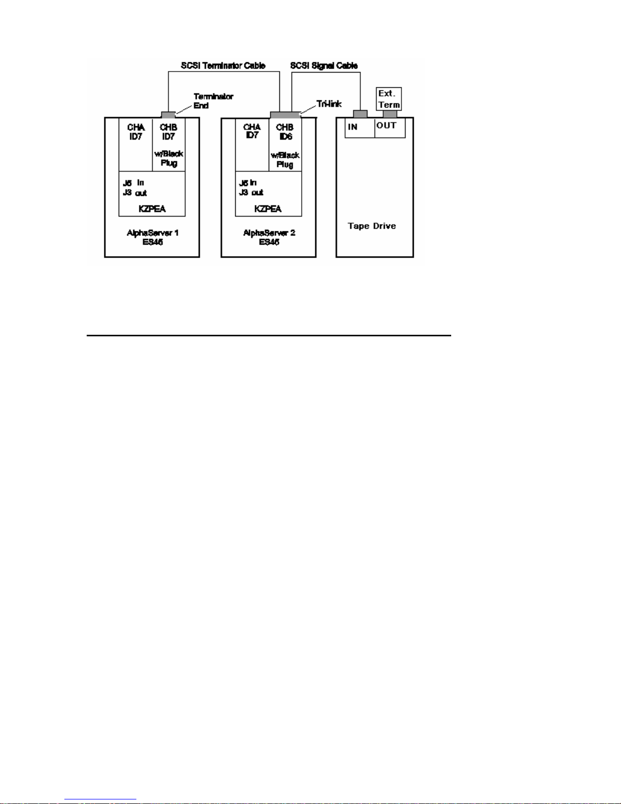
Figure 5 Shared Tape Configuration B
KZPEA Adapter Configuration for Shared Tape Installation
The following steps describe the procedure to disable on-board termination, and also to change one of the
adapter’s SCSI ID to 6.
Refer to the system and KZPEA User’s Guides for proper system shutdown, power off and ESD
protections.
1) Disconnect any attached cables and remove the on board termination jumper for the bus being
configured as a shared bus: J3 for Channel 2/B and J5 for Channel 1/A. Refer to the KZPEA User’s Guide
for location of these termination jumpers.
2) Power-up both AlphaServer systems, and at the console prompts perform the following:
f) Type "show config" to display the system configuration information.
g) Determine the name of the KZPEA adapter: e.g. pkc0, pkd0, etc.
h) Type "init" to reinitialize the system prior to using the “run bios” command.
i) Type "run bios pkx0" where x is the assigned letter of the board's channel A.
j) Press CTRL-A when prompted to run the KZPEA on-board configuration utility.
19
Page 20

3) Perform the following steps in the configuration utility on both AlphaServer systems:
h) Select the channel (1/A or 2/B) that will be configured in a shared bus environment.
i) Select "Configure/View Host Adapter Settings" menu.
j) Use the arrow key to move the cursor to Host Adapter SCSI Termination, and then press RETURN
to select your options.
k) Set Host Adapter SCSI Termination = “Low OFF/High OFF” if channel 1/A was selected, or
“Disabled” if channel 2/B was selected. [NOTE: B channel has different settings than A channel]
l) On one of the shared bus AlphaServer systems, change its KZPEA SCSI ID field to 6 (default is 7)
for the appropriate channel being configured into a shared bus environment.
m) Press Esc key to get out and save the changes.
n) Press Esc key again to exit the configuration utility. The console will reset all I/O buses.
© Copyright 2006 Hewlett-Packard Development Company. L.P.
The information contained herein is subject to change without notice. The only warranties for HP products and
services are set forth in the express warranty statements accompanying such products and services. Nothing
herein should be construed as constituting an additional warranty. HP shall not be liable for technical or editorial
errors or omissions contained herein.
Printed in the U.S.A.
20
 Loading...