

Page 1

b
Maintenance and Service Guide
Compaq Evo Notebook N620c,
Evo N610c, and Evo N600c Series
Document Part Number: 279362-002
February 2003
This guide is a troubleshooting reference used for maintaining
and servicing the notebook. It provides comprehensive
information on identifying notebook features, components, and
spare parts, troubleshooting notebook problems, and performing
notebook disassembly procedures.
Page 2

© 2003 Hewlett-Packard Development Company, L.P.
Microsoft and Windows are trademarks of Microsoft Corporation in the U.S.
and/or other countries. Intel, Pentium, and Pentium-M are trademarks of Intel
Corporation in U.S. and/or other countries. All other product names mentioned
herein may be trademarks of their respective companies.
HP shall not be liable for technical or editorial errors or omissions contained
herein or for incidental or consequential damages in connection with the
furnishing, performance, or use of this material. The information in this
document is provided “as is” without warranty of any kind, and is subject to
change without notice. The warranties for HP products are set forth in the
express limited warranty statements accompanying such products. Nothing
herein should be construed as constituting an additional warranty.
Maintenance and Service Guide
Second Edition February 2003
First Edition July 2002
Document Part Number: 279362-002
Page 3

Contents
1 Product Description
1.1 Models . . . . . . . . . . . . . . . . . . . . . . . . . . . . . . . . . . . 1–2
1.2 Features . . . . . . . . . . . . . . . . . . . . . . . . . . . . . . . . . 1–26
1.3 Clearing a Password . . . . . . . . . . . . . . . . . . . . . . . . 1–28
1.4 Power Management . . . . . . . . . . . . . . . . . . . . . . . . 1–29
1.5 Notebook External Components . . . . . . . . . . . . . . 1–30
1.6 Design Overview . . . . . . . . . . . . . . . . . . . . . . . . . . 1–43
2 Troubleshooting
2.1 Computer Setup and Diagnostics Utilities . . . . . . . . 2–1
Selecting Computer Setup or
Compaq Diagnostics . . . . . . . . . . . . . . . . . . . . . . . . 2–1
Selecting from the File Menu. . . . . . . . . . . . . . . . . . 2–3
Selecting from the Security Menu . . . . . . . . . . . . . . 2–4
Selecting from the Advanced Menu. . . . . . . . . . . . . 2–5
2.2 Using Compaq Diagnostics . . . . . . . . . . . . . . . . . . . 2–7
Obtaining, Saving, or Printing
Configuration Information . . . . . . . . . . . . . . . . . . . . 2–7
Obtaining, Saving, or Printing Diagnostic
Test Information. . . . . . . . . . . . . . . . . . . . . . . . . . . . 2–8
2.3 Troubleshooting Flowcharts. . . . . . . . . . . . . . . . . . 2–10
Maintenance and Service Guide iii
Page 4

Contents
3 Illustrated Parts Catalog
3.1 Serial Number Location . . . . . . . . . . . . . . . . . . . . . . 3–1
3.2 Notebook System Major Components . . . . . . . . . . . 3–2
3.3 Miscellaneous Plastics Kit Components . . . . . . . . 3–16
3.4 Mass Storage Devices . . . . . . . . . . . . . . . . . . . . . . 3–18
3.5 Miscellaneous. . . . . . . . . . . . . . . . . . . . . . . . . . . . . 3–22
4 Removal and Replacement Preliminaries
4.1 Tools Required . . . . . . . . . . . . . . . . . . . . . . . . . . . . . 4–1
4.2 Service Considerations. . . . . . . . . . . . . . . . . . . . . . . 4–1
Plastic Parts . . . . . . . . . . . . . . . . . . . . . . . . . . . . . . . 4–2
Cables and Connectors . . . . . . . . . . . . . . . . . . . . . . . 4–2
4.3 Preventing Damage to Removable Drives . . . . . . . . 4–2
4.4 Preventing Electrostatic Damage . . . . . . . . . . . . . . . 4–3
4.5 Packaging and Transporting Precautions . . . . . . . . . 4–4
4.6 Workstation Precautions . . . . . . . . . . . . . . . . . . . . . 4–4
4.7 Grounding Equipment and Methods . . . . . . . . . . . . 4–5
5 Removal and Replacement Procedures
5.1 Serial Number . . . . . . . . . . . . . . . . . . . . . . . . . . . . . 5–2
5.2 Disassembly Sequence Chart . . . . . . . . . . . . . . . . . . 5–2
5.3 Preparing the Notebook for Disassembly. . . . . . . . . 5–4
5.4 Computer Feet . . . . . . . . . . . . . . . . . . . . . . . . . . . . 5–11
5.5 Mini PCI Communications Board . . . . . . . . . . . . . 5–12
5.6 Disk Cell RTC Battery . . . . . . . . . . . . . . . . . . . . . . 5–15
5.7 Keyboard . . . . . . . . . . . . . . . . . . . . . . . . . . . . . . . . 5–17
5.8 Memory Expansion . . . . . . . . . . . . . . . . . . . . . . . . 5–22
5.9 TouchPad . . . . . . . . . . . . . . . . . . . . . . . . . . . . . . . . 5–25
5.10 Switch Cover . . . . . . . . . . . . . . . . . . . . . . . . . . . . . 5–27
5.11 Display . . . . . . . . . . . . . . . . . . . . . . . . . . . . . . . . . . 5–29
5.12 Top Cover. . . . . . . . . . . . . . . . . . . . . . . . . . . . . . . . 5–32
5.13 System Board . . . . . . . . . . . . . . . . . . . . . . . . . . . . . 5–35
iv Maintenance and Service Guide
Page 5

5.14 Fan . . . . . . . . . . . . . . . . . . . . . . . . . . . . . . . . . . . . . 5–42
5.15 Heat Sink . . . . . . . . . . . . . . . . . . . . . . . . . . . . . . . . 5–46
5.16 Processor . . . . . . . . . . . . . . . . . . . . . . . . . . . . . . . . 5–50
5.17 DC-DC Converter Board . . . . . . . . . . . . . . . . . . . . 5–52
5.18 Modem Cable. . . . . . . . . . . . . . . . . . . . . . . . . . . . . 5–54
6 Specifications
A Connector Pin Assignments
B Power Cord Set Requirements
3-Conductor Power Cord Set . . . . . . . . . . . . . . . . . . . . . . B–1
General Requirements . . . . . . . . . . . . . . . . . . . . . . . B–1
Country-Specific Requirements . . . . . . . . . . . . . . . . . . . . B–2
C Screw Listing
Index
Contents
Maintenance and Service Guide v
Page 6
1
Product Description
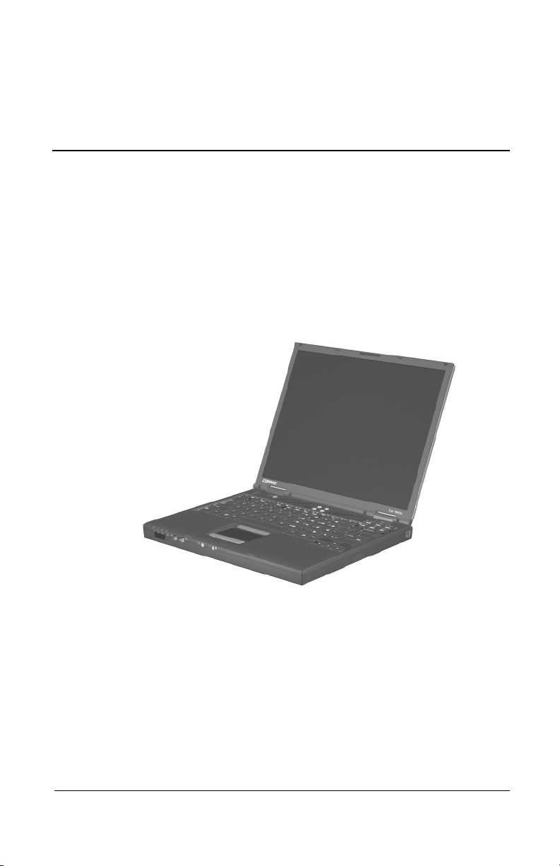
The Compaq Evo Notebook N620c, N610c, and N600c Series
offer advanced modularity, Mobile Intel Pentium 4 and Pentium
III processors with 64-bit architecture, industry-leading
Accelerated Graphics Port (AGP) implementation, and extensive
multimedia support.
Figure 1-1. Compaq Evo Notebook N620c, N610c, and N600c
Maintenance and Service Guide 1–1
Page 7

Product Description
1.1 Models
Computer models are shown in Tables 1-1 through 1-4.
Table 1-1
Compaq Evo Notebook N620c, N610c, and N600c
Model Naming Conventions
Key
N610 P4 200 P4 40 V C 25 O XXXXXX-XXX
123456789 10
Ke
y Description Options
1 Brand/Series
designator
2 Processor type P4 = Intel Pentium 4 P3 = Intel Pentium III
3 Processor speed 200 = 2.0 Ghz
4 Display type/
size/resolution
5 Hard drive size 60 = 60 GB
6 Optical drive
designator
7 Integrated
communication
N = Notebook 620 = N620c series
610 = N610c series
600 = N600c series
P = Intel Pentium-M
150 = 1.5 GHz
190 = 1.9 GHz
180 = 1.8 GHz
170 = 1.7 GHz
160 = 1.6 GHz
P = SXGA+ (1400 × 1050)
X = XGA (1024 × 768)
40 = 40 GB
30 = 30 GB
W = DVD-RW drive
V = DVD-ROM drive
M = Modem
0 = None
140 = 1.4 GHz
130 = 1.3 GHz
106 = 1.06 GHz
866 = 866 MHz
4 = 14.x-inch
20 = 20 GB
15 = 15 GB
10 = 10 GB
R = CD-RW drive
D = CD-ROM drive
C = Modem/NIC
combination card
1–2 Maintenance and Service Guide
Page 8

Product Description
Table 1-1
Compaq Evo Notebook N620c, N610c, and N600c
Model Naming Conventions
(Continued)
8 RAM 51 = 512 MB
38 = 384 MB
9 Operating system 8 = Windows 98 SE
6 = Windows 2000
and Windows XP
25 = 256 MB
12 = 128 MB
2 = Windows 2000
O = Windows XP Pro
E = Windows XP Home
10 SKU#
Table 1-2
Compaq Evo Notebook N620c Models
The following Evo Notebook N620c models feature:
■ Dual Stick pointing device (TouchPad and pointing stick)
■ 8-cell, 4.4-Ah lithium ion (Li ion) battery pack
■ 3-year warranty on parts, labor, and on-site, next business day response
■ 32 MB of discrete video memory
■ no config. code used
N620c P 140 X4 40 C X 25 2
United States DE267A ABA
N620c P 140 X4 40 C X 25 O
United States DE266A ABA
The following Evo Notebook N620c models feature:
■ Dual Stick pointing device (TouchPad and pointing stick)
■ 8-cell, 4.4-Ah Li ion battery pack
■ 3-year warranty on parts and labor
■ 32 MB of discrete video memory
■ config. code KY2Z
N620c P 160 P4 60 C G 51 2
Brazil
French Canada
DE273A AC4
DE273A ABC
Latin America
United States
DE273A ABM
DE273A ABA
Maintenance and Service Guide 1–3
Page 9

Product Description
Table 1-2
Compaq Evo Notebook N620c Models
N620c P 160 P4 60 C G 51 O
(Continued)
Brazil
French Canada
N620c P 150 P4 60 C G 51 2
Asia Pacific
Australia
Belgium
Czech Republic
Denmark
European
International
France
Germany
Greece
Hong Kong
Hungary
Iceland
India
Israel
Italy
Japan
Japan (English)
DE272A AC4
DE272A ABC
DE271A UUF
DE271A ABG
DE271A UUG
DE271A AKB
DE271A ABY
DE271A ABB
DE271A ABF
DE271A ABD
DE271A ABV
DE271A AB5
DE271A AKC
DE271A A2M
DE271A ACJ
DE271A ABT
DE271A ABZ
DE271A ABJ
DE271A ACF
Latin America
United States
Korea
The Netherlands
Norway
People’s
Republic
of China
Poland
Portugal
Russia
Saudi Arabia
Slovenia
Spain
Sweden/Finland
Switzerland
Ta i wa n
Thailand
Tu r ke y
United Kingdom
DE272A ABM
DE272A ABA
DE271A AB1
DE271A ABH
DE271A ABN
DE271A AB2
DE271A AKD
DE271A AB9
DE271A ACB
DE271A ABV
DE271A AKN
DE271A ABE
DE271A AK8
DE271A UUZ
DE271A AB0
DE271A AKL
DE271A AB8
DE271A ABU
1–4 Maintenance and Service Guide
Page 10

Table 1-2
Compaq Evo Notebook N620c Models
N620c P 150 P4 60 C G 51 O
(Continued)
Product Description
Asia Pacific
Australia
Belgium
Czech Republic
Denmark
European
International
France
Germany
Greece
Hong Kong
Hungary
Iceland
India
Israel
Italy
Japan
Japan (English)
DE270A UUF
DE270A ABG
DE270A UUG
DE270A AKB
DE270A ABY
DE270A ABB
DE270A ABF
DE270A ABD
DE270A ABV
DE270A AB5
DE270A AKC
DE270A A2M
DE270A ACJ
DE270A ABT
DE270A ABZ
DE270A ABJ
DE270A ACF
Korea
The Netherlands
Norway
People’s
Republic
of China
Poland
Portugal
Russia
Saudi Arabia
Slovenia
Spain
Sweden/Finland
Switzerland
Ta i wa n
Thailand
Tu r ke y
United Kingdom
DE270A AB1
DE270A ABH
DE270A ABN
DE270A AB2
DE270A AKD
DE270A AB9
DE270A ACB
DE270A ABV
DE270A AKN
DE270A ABE
DE270A AK8
DE270A UUZ
DE270A AB0
DE270A AKL
DE270A AB8
DE270A ABU
Maintenance and Service Guide 1–5
Page 11

Product Description
Table 1-2
Compaq Evo Notebook N620c Models
N620c P 140 X4 40 C X 25 2
(Continued)
Asia Pacific
Australia
Belgium
Brazil
Czech Republic
Denmark
European
International
France
French Canada
Germany
Greece
Hong Kong
Hungary
Iceland
India
Israel
Italy
Japan
Japan (English)
DE265A UUF
DE265A ABG
DE265A UUG
DE265A AC4
DE265A AKB
DE265A ABY
DE265A ABB
DE265A ABF
DE265A ABC
DE265A ABD
DE265A ABV
DE265A AB5
DE265A AKC
DE265A A2M
DE265A ACJ
DE265A ABT
DE265A ABZ
DE265A ABJ
DE265A ACF
Koran
Latin America
The Netherlands
Norway
People’s
Republic
of China
Poland
Portugal
Russia
Saudi Arabia
Slovenia
Spain
Sweden/Finland
Switzerland
Ta i wa n
Thailand
Tu r ke y
United Kingdom
United States
DE265A AB1
DE265A ABM
DE265A ABH
DE265A ABN
DE265A AB2
DE265A AKD
DE265A AB9
DE265A ACB
DE265A ABV
DE265A AKN
DE265A ABE
DE265A AK8
DE265A UUZ
DE265A AB0
DE265A AKL
DE265A AB8
DE265A ABU
DE265A ABA
1–6 Maintenance and Service Guide
Page 12

Table 1-2
Compaq Evo Notebook N620c Models
N620c P 140 X4 40 C X 25 O
(Continued)
Product Description
Asia Pacific
Australia
Belgium
Brazil
Czech Republic
Denmark
European
International
France
French Canada
Germany
Greece
Hong Kong
Hungary
Iceland
India
Israel
Italy
Japan
Japan (English)
N620c P 140 X4 40 C 8 25 2
Denmark
Germany
Italy
Norway
DE264A UUF
DE264A ABG
DE264A UUG
DE264A AC4
DE264A AKB
DE264A ABY
DE264A ABB
DE264A ABF
DE264A ABC
DE264A ABD
DE264A ABV
DE264A AB5
DE264A AKC
DE264A A2M
DE264A ACJ
DE264A ABT
DE264A ABZ
DE264A ABJ
DE264A ACF
DE269A ABY
DE269A ABD
DE269A ABZ
DE269A ABN
Korea
Latin America
The Netherlands
Norway
People’s
Republic
of China
Poland
Portugal
Russia
Saudi Arabia
Slovenia
Spain
Sweden/Finland
Switzerland
Ta i wa n
Thailand
Tu r ke y
United Kingdom
United States
Sweden/Finland
Switzerland
United States
DE264A AB1
DE264A ABM
DE264A ABH
DE264A ABN
DE264A AB2
DE264A AKD
DE264A AB9
DE264A ACB
DE264A ABV
DE264A AKN
DE264A ABE
DE264A AK8
DE264A UUZ
DE264A AB0
DE264A AKL
DE264A AB8
DE264A ABU
DE264A ABA
DE269A AK8
DE269A UUZ
DE269A ABA
N620c P 140 X4 40 C 8 25 O
Denmark
Germany
Italy
Norway
DE268A ABY
DE268A ABD
DE268A ABZ
DE268A ABN
Sweden/Finland
Switzerland
United States
DE268A AK8
DE268AUUZ
DE268A ABA
Maintenance and Service Guide 1–7
Page 13

Product Description
Table 1-2
Compaq Evo Notebook N620c Models
N620c P 130 X4 30 C X 25 2
(Continued)
Asia Pacific
Australia
Belgium
Brazil
Czech Republic
Denmark
European
International
France
French Canada
Germany
Greece
Hong Kong
Hungary
Iceland
India
Israel
Italy
Japan
Japan (English)
DE263A UUF
DE263A ABG
DE263A UUG
DE263A AC4
DE263A AKB
DE263A ABY
DE263A ABB
DE263A ABF
DE263A ABC
DE263A ABD
DE263A ABV
DE263A AB5
DE263A AKC
DE263A A2M
DE263A ACJ
DE263A ABT
DE263A ABZ
DE263A ABJ
DE263A ACF
Korea
Latin America
The Netherlands
Norway
People’s
Republic
of China
Poland
Portugal
Russia
Saudi Arabia
Slovenia
Spain
Sweden/Finland
Switzerland
Ta i wa n
Thailand
Tu r ke y
United Kingdom
United States
DE263A AB1
DE263A ABM
DE263A ABH
DE263A ABN
DE263A AB2
DE263A AKD
DE263A AB9
DE263A ACB
DE263A ABV
DE263A AKN
DE263A ABE
DE263A AK8
DE263A UUZ
DE263A AB0
DE263A AKL
DE263A AB8
DE263A ABU
DE263A ABA
1–8 Maintenance and Service Guide
Page 14

Table 1-2
Compaq Evo Notebook N620c Models
N620c P 130 X4 30 C X 25 O
(Continued)
Product Description
Asia Pacific
Australia
Belgium
Brazil
Czech Republic
Denmark
European
International
France
French Canada
Germany
Greece
Hong Kong
Hungary
Iceland
India
Israel
Italy
Japan
Japan (English)
DE262A UUF
DE262A ABG
DE262A UUG
DE262A AC4
DE262A AKB
DE262A ABY
DE262A ABB
DE262A ABF
DE262A ABC
DE262A ABD
DE262A ABV
DE262A AB5
DE262A AKC
DE262A A2M
DE262A ACJ
DE262A ABT
DE262A ABZ
DE262A ABJ
DE262A ACF
Korea
Latin America
The Netherlands
Norway
People’s
Republic
of China
Poland
Portugal
Russia
Saudi Arabia
Slovenia
Spain
Sweden/Finland
Switzerland
Ta i wa n
Thailand
Tu r ke y
United Kingdom
United States
DE262A AB1
DE262A ABM
DE262A ABH
DE262A ABN
DE262A AB2
DE262A AKD
DE262A AB9
DE262A ACB
DE262A ABV
DE262A AKN
DE262A ABE
DE262A AK8
DE262A UUZ
DE262A AB0
DE262A AKL
DE262A AB8
DE262A ABU
DE262A ABA
Maintenance and Service Guide 1–9
Page 15

Product Description
Table 1-3
Compaq Evo Notebook N610c Models
The following Evo Notebook N610c models feature:
■ Dual Stick pointing device (TouchPad and pointing stick)
■ 8-cell, 4.0-Ah Li ion battery pack
■ 3-year warranty on parts, labor, and on-site, next business day response
■ 32 MB of discrete video memory
■ config. code KT81
N610 P4 200 X4 30 V C 25 2
United States 470050-082
N610 P4 200 X4 30 V C 25 O
United States 470050-083
N610 P4 200 X4 30 C 0 0 2
United States 470050-733
N610 P4 200 X4 30 C 0 0 O
United States 470050-734
N610 P4 180 X4 30 V C 25 2
United States 470037-720
N610 P4 180 X4 30 V C 25 O
United States 470037-722
N610 P4 180 X4 30 0 C 0 2
United States 470037-542
N610 P4 180 X4 30 0 C 0 O
United States 470037-549
1–10 Maintenance and Service Guide
Page 16

Table 1-3
Compaq Evo Notebook N610c Models
The following Evo Notebook N610c models feature:
■ Dual Stick pointing device (TouchPad and pointing stick)
■ 8-cell, 4.0-Ah Li ion battery pack
■ 3-year warranty on parts and labor
■ 32 MB of discrete video memory
■ config. code KT8Z
N610 P4 200 P4 40 W C 25 2
(Continued)
Product Description
Belgium
Czech Republic
Denmark
France
French Canada
Germany
Greece/Poland
Hungary
Israel
Italy
The Netherlands
470050-913
470050-914
470050-919
470050-920
470037-754
470050-921
470050-922
470050-923
470050-924
470050-925
470050-926
Norway
Portugal
Russia
Saudi Arabia
Slovenia
Spain
Sweden/Finland
Switzerland
Tu r ke y
United Kingdom
United States
470050-927
470050-928
470050-929
470050-911
470050-930
470050-931
470050-932
470050-933
470050-934
470050-936
470037-749
Maintenance and Service Guide 1–11
Page 17

Product Description
Table 1-3
Compaq Evo Notebook N610c Models
N610 P4 200 P4 40 W C 25 E
(Continued)
Asia Pacific
Australia
Belgium
Brazil
Czech Republic
Denmark
European
International
France
French Canada
Germany
Greece/Poland
Hong Kong
Hungary
Israel
Italy
Japan
Japan (English)
N610 P4 200 P4 40 W C 25 O
Belgium
Czech Republic
Denmark
France
French Canada
Germany
Greece/Poland
Hungary
Israel
Italy
The Netherlands
470050-987
470050-986
470050-963
470050-985
470050-964
470050-965
470054-625
470050-966
470050-961
470050-967
470050-968
470050-990
470050-969
470050-970
470050-971
470050-982
470050-983
470050-939
470050-940
470050-941
470050-942
470037-755
470050-943
470050-944
470050-946
470050-948
470050-949
470050-950
Korea
Latin America
The Netherlands
Norway
People’s
Republic
of China
Portugal
Russia
Saudi Arabia
Slovenia
Spain
Sweden/Finland
Switzerland
Ta i wa n
Tu r ke y
United Kingdom
United States
Norway
Portugal
Russia
Saudi Arabia
Slovenia
Spain
Sweden/Finland
Switzerland
Tu r ke y
United Kingdom
United States
470050-991
470050-984
470050-972
470050-973
470050-988
470050-974
470050-975
470050-962
470050-976
470050-977
470050-978
470050-979
470050-989
470050-980
470050-981
470050-960
470050-951
470050-952
470050-953
470050-938
470050-954
470050-955
470050-956
470050-957
470050-958
470050-959
470037-757
1–12 Maintenance and Service Guide
Page 18

Table 1-3
Compaq Evo Notebook N610c Models
N610 P4 200 X4 30 V C 25 2
Asia Pacific
Australia
Belgium
Brazil
Czech Republic
Denmark
France
French Canada
Germany
Greece/Poland
Hong Kong
Hungary
Israel
Italy
Japan
Japan (English)
Korea
Latin America
Latin America
(GEM/NAFTA)
470050-438
470050-421
470050-371
470050-419
470050-374
470050-378
470050-379
470050-358
470050-386
470050-392
470050-443
470050-393
470050-395
470050-396
470050-416
470050-417
470050-446
470050-418
470050-532
The Netherlands
Norway
People’s
Republic
of China
Portugal
Russia
Saudi Arabia
Slovenia
Spain
Sweden/Finland
Switzerland
Ta i wa n
Tu r ke y
United Kingdom
United States
United States
(GEM/NAFTA)
Product Description
(Continued)
470050-398
470050-400
470050-439
470050-403
470050-404
470050-360
470050-405
470050-407
470050-410
470050-412
470050-440
470050-414
470050-415
470050-020
470050-531
Maintenance and Service Guide 1–13
Page 19

Product Description
Table 1-3
Compaq Evo Notebook N610c Models
N610 P4 200 X4 30 V C 25 E
Asia Pacific
Australia
Belgium
Brazil
Czech Republic
Denmark
France
French Canada
Germany
Greece/Poland
Hong Kong
Hungary
Israel
Italy
Japan
Japan (English)
Korea
470050-572
470050-571
470050-538
470050-570
470050-539
470050-541
470050-544
470050-536
470050-547
470050-548
470050-575
470050-549
470050-550
470050-552
470050-567
470050-568
470050-576
Latin America
The Netherlands
Norway
People’s
Republic
of China
Portugal
Russia
Saudi Arabia
Slovenia
Spain
Sweden/Finland
Switzerland
Ta i wa n
Tu r ke y
United Kingdom
United States
(Continued)
470050-569
470050-555
470050-558
470050-573
470050-559
470050-560
470050-537
470050-561
470050-562
470050-563
470050-564
470050-574
470050-565
470050-566
470050-535
1–14 Maintenance and Service Guide
Page 20

Table 1-3
Compaq Evo Notebook N610c Models
N610 P4 200 X4 30 V C 25 O
Asia Pacific
Australia
Belgium
Brazil
Czech Republic
Denmark
France
French Canada
Germany
Greece/Poland
Hong Kong
Hungary
Israel
Italy
Japan
Japan (English)
Korea
Latin America
Latin America
(GEM/NAFTA)
470050-502
470050-498
470050-456
470050-497
470050-457
470050-458
470050-459
470050-454
470050-460
470050-462
470050-507
470050-468
470050-469
470050-470
470050-490
470050-491
470050-512
470050-496
470050-534
The Netherlands
Norway
People’s
Republic
of China
Portugal
Russia
Saudi Arabia
Slovenia
Spain
Sweden/Finland
Switzerland
Ta i wa n
Tu r ke y
United Kingdom
United States
United States
(GEM/NAFTA)
Product Description
(Continued)
470050-471
470050-473
470050-505
470050-477
470050-478
470050-455
470050-480
470050-482
470050-486
470050-487
470050-506
470050-488
470050-489
470050-021
470050-533
Maintenance and Service Guide 1–15
Page 21

Product Description
Table 1-3
Compaq Evo Notebook N610c Models
N610 P4 180 X4 30 V C 25 2
Asia Pacific
Australia
Belgium
Brazil
Czech Republic
Denmark
European
International
France
French Canada
Germany
Greece/Poland
Hong Kong
Hungary
Israel
Italy
Japan
Japan (English)
Korea
Latin America
Latin America
(GEM/NAFTA)
470037-572
470037-570
470037-529
470037-569
470037-530
470037-531
470048-135
470037-532
470037-527
470037-533
470037-535
470037-584
470037-537
470037-538
470037-539
470037-561
470037-563
470037-587
470037-566
470037-726
The Netherlands
Norway
People’s
Republic
of China
Portugal
Russia
Saudi Arabia
Slovenia
Spain
Sweden/Finland
Switzerland
Ta i wa n
Tu r ke y
United Kingdom
United States
United States
(GEM/NAFTA)
(Continued)
470037-541
470037-543
470037-577
470037-545
470037-546
470037-528
470037-548
470037-551
470037-552
470037-555
470037-580
470037-556
470037-558
470037-525
470037-724
1–16 Maintenance and Service Guide
Page 22

Table 1-3
Compaq Evo Notebook N610c Models
N610 P4 180 X4 30 V C 25 E
(Continued)
Product Description
Asia Pacific
Australia
Belgium
Brazil
Czech Republic
Denmark
European
International
France
French Canada
Germany
Greece/Poland
Hong Kong
Hungary
Israel
Italy
Japan
Japan (English)
470044-442
470044-441
470044-410
470044-440
470044-411
470044-412
470048-137
470044-416
470044-408
470044-417
470044-418
470044-445
470044-419
470044-420
470044-421
470044-436
470044-438
Korea
Latin America
The Netherlands
Norway
People’s
Republic
of China
Portugal
Russia
Saudi Arabia
Slovenia
Spain
Sweden/Finland
Switzerland
Ta i wa n
Tu r ke y
United Kingdom
United States
470044-446
470044-439
470044-422
470044-423
470044-443
470044-424
470044-425
470044-409
470044-426
470044-427
470044-429
470044-431
470044-444
470044-433
470044-434
470042-693
Maintenance and Service Guide 1–17
Page 23

Product Description
Table 1-3
Compaq Evo Notebook N610c Models
N610 P4 180 X4 30 V C 25 O
Asia Pacific
Australia
Belgium
Brazil
Czech Republic
Denmark
European
International
France
French Canada
Germany
Greece/Poland
Hong Kong
Hungary
Israel
Italy
Japan
Japan (English)
Korea
Latin America
Latin America
(GEM/NAFTA)
470037-714
470037-713
470037-687
470037-712
470037-688
470037-689
470048-136
470037-690
470037-685
470037-691
470037-692
470037-717
470037-693
470037-694
470037-695
470037-707
470037-708
470037-718
470037-710
470037-747
The Netherlands
Norway
People’s
Republic
of China
Portugal
Russia
Saudi Arabia
Slovenia
Spain
Sweden/Finland
Switzerland
Ta i wa n
Tu r ke y
United Kingdom
United States
United States
(GEM/NAFTA)
(Continued)
470037-696
470037-697
470037-709
470037-699
470037-700
470037-686
470037-701
470037-702
470037-703
470037-704
470037-715
470037-705
470037-706
470037-684
470037-746
N610 P4 180 X4 20 D C 25 2
Belgium
Czech Republic
Denmark
France
Germany
Greece/Poland
Hungary
Israel
Italy
The Netherlands
470050-736
470050-737
470050-739
470050-740
470050-741
470050-742
470050-743
470050-744
470050-746
470050-747
Norway
Portugal
Russia
Saudi Arabia
Slovenia
Spain
Sweden/Finland
Switzerland
Tu r ke y
United Kingdom
470050-749
470050-750
470050-751
470050-735
470050-752
470050-753
470050-754
470050-755
470050-757
470050-637
1–18 Maintenance and Service Guide
Page 24

Table 1-3
Compaq Evo Notebook N610c Models
N610 P4 180 X4 20 D C 25 O
(Continued)
Product Description
Belgium
Czech Republic
Denmark
France
Germany
Greece/Poland
Hungary
Israel
Italy
The Netherlands
N610 P4 160 X4 20 V C 25 2
French Canada
United States
N610 P4 160 X4 20 V C 25 O
French Canada
United States
470050-772
470050-773
470050-774
470050-775
470050-776
470050-780
470050-781
470050-782
470050-783
470050-784
470037-664
470037-661
470037-736
470037-733
Norway
Portugal
Russia
Saudi Arabia
Slovenia
Spain
Sweden/Finland
Switzerland
Tu r ke y
United Kingdom
United States
(GEM/NAFTA)
United States
(GEM/NAFTA)
470050-785
470050-786
470050-787
470050-771
470050-790
470050-792
470050-825
470050-826
470050-827
470050-636
470037-738
470037-741
Maintenance and Service Guide 1–19
Page 25

Product Description
Table 1-3
Compaq Evo Notebook N610c Models
N610 P4 160 X4 20 D C 25 2
(Continued)
Belgium
Czech Republic
Denmark
France
Germany
Greece/Poland
Hungary
Israel
Italy
The Netherlands
N610 P4 160 X4 20 D C 25 O
Belgium
Czech Republic
Denmark
France
Germany
Greece/Poland
Hungary
Israel
Italy
The Netherlands
470037-567
470037-571
470037-573
470037-578
470037-581
470037-585
470037-586
470037-588
470037-595
470037-601
470037-619
470037-620
470037-621
470037-622
470037-623
470037-625
470037-627
470037-630
470037-633
470037-636
Norway
Portugal
Russia
Saudi Arabia
Slovenia
Spain
Sweden/Finland
Switzerland
Tu r ke y
United Kingdom
Norway
Portugal
Russia
Saudi Arabia
Slovenia
Spain
Sweden/Finland
Switzerland
Tu r ke y
United Kingdom
470037-602
470037-604
470037-605
470037-562
470037-606
470037-607
470037-608
470037-613
470037-616
470037-617
470037-639
470037-641
470037-644
470037-618
470037-646
470037-648
470037-650
470037-653
470037-656
470037-658
1–20 Maintenance and Service Guide
Page 26

Product Description
Table 1-4
Compaq Evo Notebook N600c Models
The following Evo Notebook N600c models feature:
■ Dual Stick pointing device (TouchPad and pointing stick)
■ 8-cell, 4.0-Ah Li ion battery pack
■ 3-year warranty on parts, labor, and on-site, next business day response
■ 32 MB of discrete video memory
■ config. code KBS1
N600 P3 120 X4 30 V C 25 2
United States 470053-840
N600 P3 120 X4 30 V C 25 0
United States 470053-832
The following Evo Notebook N600c models feature:
■ Dual Stick pointing device (TouchPad and pointing stick)
■ 8-cell, 4.0-Ah Li ion battery pack
■ 3-year warranty on parts and labor
■ 32 MB of discrete video memory
■ config. code KBSZ
N600 P3 120 P4 30 W C 25 2
United States 470023-406
N600 P3 120 P4 30 W C 25 0
United States 470053-613
Maintenance and Service Guide 1–21
Page 27

Product Description
Table 1-4
Compaq Evo Notebook N600c Models
N600 P3 120 P4 30 V C 25 2
(Continued)
Belgium
Czech Republic
Denmark
France
Germany
Greece/Poland
Hungary
Israel
Italy
The Netherlands
Norway
Portugal
N600 P3 120 P4 30 V C 25 O
Belgium
Czech Republic
Denmark
France
Germany
Greece/Poland
Hungary
Israel
Italy
The Netherlands
Norway
Portugal
470023-411
470023-412
470023-415
470023-416
470023-419
470023-420
470023-422
470023-426
470023-427
470053-660
470023-432
470023-433
470053-561
470053-562
470053-563
470053-564
470053-565
470053-566
470053-568
470053-570
470053-571
470053-573
470053-574
470053-575
Russia
Saudi Arabia
Slovakia/
Slovenia
Spain
Sweden/Finland
Switzerland
Tu r ke y
United Kingdom
Russia
Saudi Arabia
Slovakia/
Slovenia
Spain
Sweden/Finland
Switzerland
Tu r ke y
United Kingdom
470023-436
470023-430
470023-437
470023-440
470023-441
470023-444
and
470023-447
470023-448
470023-452
470053-576
470053-572
470053-577
470053-578
470053-579
470053-580
and
470053-581
470053-582
470053-583
N600 P3 120 P4 30 V 0 25 2
European
International
N600 P3 120 P4 30 V 0 25 0
European
International
470023-460
470053-691
1–22 Maintenance and Service Guide
Page 28

Table 1-4
Compaq Evo Notebook N600c Models
N600 P3 120 X4 30 V C 25 2
(Continued)
Product Description
Asia Pacific
Australia
Belgium
Brazil
Czech Republic
Denmark
France
French Canada
Germany
Greece/Poland
Hong Kong
Hungary
Israel
Italy
Japan
Japan (English)
Korea
Latin America
The Netherlands
470053-685
470053-686
470053-628
470053-684
470053-631
470053-640
470053-644
470053-619
470053-646
470053-649
470053-689
470053-651
470053-653
470053-655
470053-681
470053-682
470053-690
470053-683
470053-659
Norway
People’s
Republic
of China
Portugal
Russia
Saudi Arabia
Slovakia/
Slovenia
Spain
Sweden/Finland
Switzerland
Ta i wa n
Tu r ke y
United Kingdom
United States
470053-662
470053-687
470053-664
470053-666
470053-657
470053-668
470053-670
470053-672
470053-674
and
470053-676
470053-688
470053-678
470053-680
470053-607
Maintenance and Service Guide 1–23
Page 29

Product Description
Table 1-4
Compaq Evo Notebook N600c Models
N600 P3 120 X4 30 V C 25 O
(Continued)
Asia Pacific
Australia
Belgium
Brazil
Czech Republic
Denmark
France
French Canada
Germany
Greece/Poland
Hong Kong
Hungary
Israel
Italy
Japan
Japan (English)
Korea
Latin America
The Netherlands
N600 P3 100 X4 20 D C 25 6
Greece/Poland
Hungary
Portugal
470053-592
470053-594
470053-624
470053-590
470053-634
470053-643
470053-645
470053-559
470053-647
470053-648
470053-603
470053-650
470053-652
470053-654
470053-585
470053-586
470053-605
470053-587
470053-658
470029-002
470029-054
470029-056
Norway
People’s
Republic
of China
Portugal
Russia
Saudi Arabia
Slovakia/
Slovenia
Spain
Sweden/Finland
Switzerland
Ta i wa n
Tu r ke y
United Kingdom
United States
Russia
Tu r ke y
470053-661
470053-597
470053-663
470053-665
470053-656
470053-667
470053-669
470053-671
470053-673
and
470053-675
470053-600
470053-677
470053-679
470053-558
470029-058
470029-060
1–24 Maintenance and Service Guide
Page 30

Table 1-4
Compaq Evo Notebook N600c Models
N600 P3 100 X4 20 D C 12 8
(Continued)
Product Description
Belgium
Czech Republic
Denmark
France
Germany
Greece/Poland
Hungary
Israel
Italy
The Netherlands
Norway
Portugal
N600 P3 100 X4 20 D C 12 6
Belgium
Czech Republic
Denmark
France
Germany
Israel
Italy
The Netherlands
Norway
N600 P3 100 X4 20 D 0 25 O
European
International
470029-930
470029-936
470029-939
470029-941
470029-945
470029-951
470029-982
470029-983
470029-984
470029-986
470029-987
470029-988
470029-192
470029-195
470029-207
470029-212
470029-214
470029-217
470029-224
470029-227
470029-228
470030-001
Russia
Saudi Arabia
Slovakia/
Slovenia
Spain
Sweden/Finland
Switzerland
Tu r ke y
United Kingdom
Saudi Arabia
Slovakia/
Slovenia
Spain
Sweden/Finland
Switzerland
United Kingdom
470029-989
470029-985
470029-990
470029-991
470029-992
470029-993
and
470029-995
470029-996
470029-997
470029-226
470029-231
470029-232
470029-234
470029-238
and
470029-240
470029-242
N600 P3 100 X4 20 D 0 25 8
European
International
470029-998
Maintenance and Service Guide 1–25
Page 31

Product Description
1.2 Features
■ The following processors are available, varying by notebook
model:
❏ The Evo Notebook N620c features an Intel Pentium-M
1.6-, 1.5-, 1.4-, or 1.3-GHz processor, with 512-KB
integrated L2 cache.
❏ The Evo Notebook N610c features a Mobile Intel
Pentium 4 2.0-, 1.9-, 1.8-, 1.7-, or 1.6-GHz processor,
with 512-KB integrated L2 cache.
❏ The Evo Notebook N600c features a Mobile Intel
Pentium III 1.066 GHz-M or 866-MHz-M processor,
with 512-KB integrated L2 cache.
■ ATI Mobility Radeon with 64-bit video graphics,
16-MB double date rate (DDR) SDRAM, 4X AGP
graphics card
■ The following memory configurations are available, varying
by notebook model:
❏ The Evo Notebook N620c and N610c feature 256-MB
high-performance Synchronous DRAM (SDRAM),
expandable to 2048 MB
❏ The Evo Notebook N600c features 256- or 128-MB
high-performance Synchronous DRAM (SDRAM),
expandable to 1024 MB
■ Microsoft Windows 98 SE, Windows 2000, or Windows XP
preinstalled, varying by notebook model
■ 14.1-inch, SXGA+ (1400 × 1050) or XGA (1024 × 768),
TFT display with over 16.8 million colors, varying by
computer model
■ Full-size TouchPad or Dual Stick keyboard, varying by
notebook model
1–26 Maintenance and Service Guide
Page 32

Product Description
■ Mini PCI 10/100 network interface card (NIC) or Mini
PCI V.90 modem plus 10/100 NIC combination card,
varying by notebook model
■ Support for two Type II PC Card slots with support for both
32-bit CardBus and 16-bit PC Cards
■ External AC adapter with power cord
■ 8-cell Li ion battery pack
■ 60-, 40-, 30-, 20-, 15-, or 10-GB high-capacity hard drive
■ Connectors for:
❏ RJ-11 modem
❏ Mono microphone
❏ Stereo line-out/headphone
❏ MultiPort
❏ Universal serial bus (USB)
❏ Docking
❏ Parallel devices
❏ Serial devices
❏ Composite TV
❏ External keyboard/mouse
❏ RJ-45 network
❏ External monitor
❏ AC power
■ Stereo speakers providing Compaq Premier·Sound 16-bit
stereo sound
Maintenance and Service Guide 1–27
Page 33

Product Description
1.3 Clearing a Password
If the notebook you are servicing has an unknown password,
follow these steps to clear the password. These steps also
clear CMOS.
1. Prepare the notebook for disassembly (refer to Section 5.3,
“Preparing the Notebook for Disassembly,” for more
information).
2. Remove the RTC battery (refer to Section 5.6, “Disk Cell
RTC Battery”).
3. Wait approximately five minutes.
4. Replace the RTC battery and reassemble the notebook.
5. Connect AC power to the notebook. Do not reinsert any
battery packs at this time.
6. Turn on the notebook.
All passwords and all CMOS settings have been cleared.
1–28 Maintenance and Service Guide
Page 34

1.4 Power Management
The notebook comes with power management features that
extend battery operating time and conserve power. The notebook
supports the following power management features:
■ Standby
■ Hibernation
■ Setting customization by the user
■ Hotkeys for setting level of performance
■ Smart battery that provides an accurate battery power gauge
■ Battery calibration
■ Lid switch suspend/resume
■ Power/suspend button
■ Advanced Configuration and Power Management (ACP)
compliance
Product Description
Maintenance and Service Guide 1–29
Page 35
Product Description
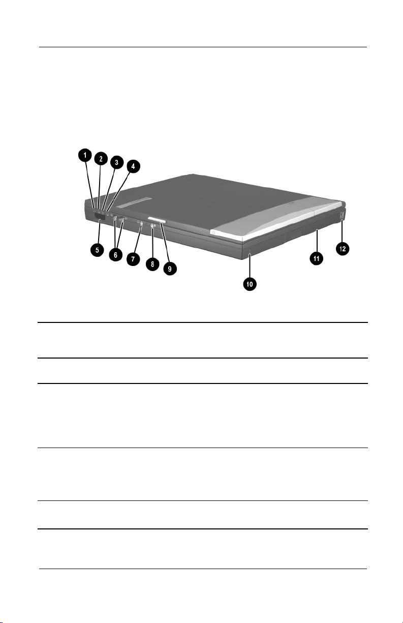
1.5 Notebook External Components
The external components on the front and right side of the
Evo Notebook N620c, N610c, and N600c are shown in Figure
1-2 and described in Table 1-5.
.
Figure 1-2. Front and Right Side Components
Table 1-5
Front and Right Side Panel Components
Item Component Function
1 Power light On: Power is turned on.
Blinking: Notebook is in Standby. The power
light also blinks if a battery pack that is the
only available power source reaches a
low-battery condition.
2 Battery light On: A battery pack is charging.
Blinking: A battery pack that is the only
available power source has reached a
low-battery condition.
3 Drive activity light Turns on when the hard drive, CD-, or
DVD-ROM drive is accessed.
1–30 Maintenance and Service Guide
Page 36

Product Description
Table 1-5
Front and Right Side Panel Components
Item Component Function
4 Media Bay light Turns on when the diskette drive in the
Media Bay or the optional external diskette
drive is accessed.
5 Infrared port Links to another IrDA-compliant device for
wireless communication.
6 Volume control buttons Adjust the volume of the stereo speakers.
(Continued)
7 Stereo line-out/
headphone jack
8 Mono microphone jack Connects a mono microphone, disabling the
9 Display release latch Opens the notebook.
10 Security cable slot Attaches an optional security cable to the
11 Media Bay Accepts a diskette drive, CD- or DVD-ROM
12 RJ-11 jack (internal
modem models only)
Connects stereo speakers, headphones,
headset, or television audio.
built-in microphone.
notebook.
drive, or secondary battery pack.
Connects the modem cable to an internal
modem. A modem cable is included with
internal modem models.
Maintenance and Service Guide 1–31
Page 37
Product Description
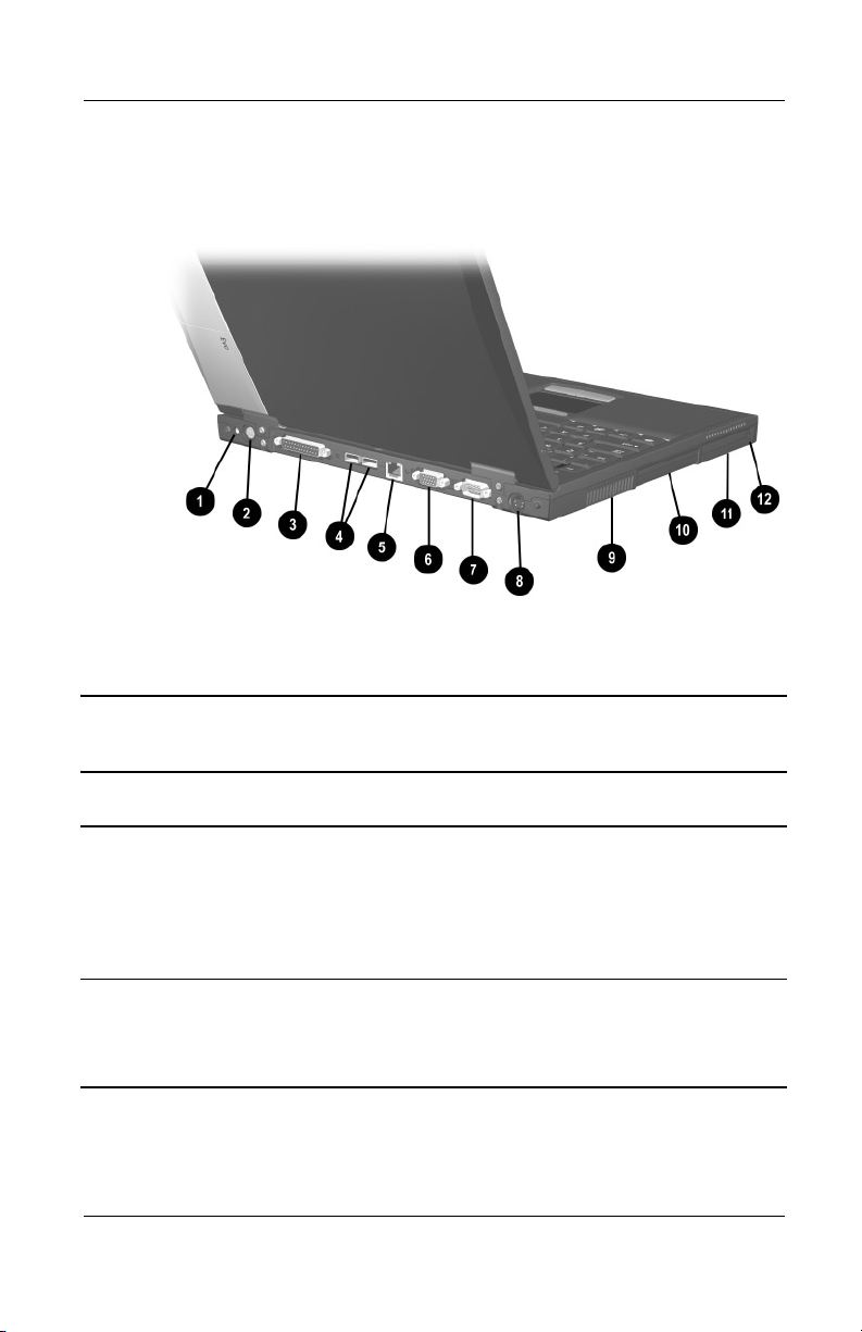
The Evo Notebook N620c, N610c, and N600c right side and rear
panel components are shown in Figure 1-3 and described in
Table 1-6.
Figure 1-3. Right Side and Rear Panel Components—
Evo Notebook N610c
Table 1-6
Right Side and Rear Panel Components
Item Component Function
1 DC power jack Connects any one of the following:
■ AC adapter
■ Optional automobile power
adapter/charger
■ Optional aircraft power adapter
2 Keyboard/mouse
connector
1–32 Maintenance and Service Guide
Connects an external keyboard or
PS/2-compatible external mouse. To
connect a keyboard and a mouse at the
same time, use an optional Y-adapter.
Page 38

Table 1-6
Right Side and Rear Panel Components
Item Component Function
3 Parallel connector Connects a parallel device.
4 USB connectors (2) Connect USB devices.
(Continued)
Product Description
5RJ-45 jack
(network models only)
6 Serial connector Connects a serial device.
7 External monitor
connector
8 S-Video connector Connects a television, VCR, camcorder, or
9 Vent Allows airflow to cool internal components.
10 Hard drive Supports the removable primary hard drive.
11 PC Card slots Support a 32-bit (CardBus) or 16-bit
12 PC Card eject buttons Eject a PC Card from a PC Card slot.
Connects the network cable. A network
cable is not included with the notebook.
Connects an external monitor or overhead
projector.
overhead projector.
To prevent damage, the notebook
Ä
shuts down if an overheating
condition occurs. Do not block the
cooling vent. Avoid placing the
notebook on a blanket, rug, or other
flexible surface that may cover the
vent area.
PC Card.
Maintenance and Service Guide 1–33
Page 39

Product Description
The Evo Notebook N600c right side and rear panel components
are shown in Figure 1-4 and described in Table 1-7.
Figure 1-4. Right Side and Rear Panel Components—
Evo Notebook N600c
Right Side and Rear Panel Components
Table 1-7
Item Component Function
1 MultiPort Connects wireless communication devices,
such as an optional Bluetooth or 802.11b
MultiPort module, and other options.
2 DC power jack Connects any one of the following:
■ AC adapter
■ Optional automobile power
adapter/charger
■ Optional aircraft power adapter
1–34 Maintenance and Service Guide
Page 40

Table 1-7
Right Side and Rear Panel Components
Item Component Function
Product Description
(Continued)
3 Keyboard/mouse
connector
4 Parallel connector Connects a parallel device.
5 Docking connector Connects the computer to the optional
6 Serial connector Connects a serial device.
7 External monitor
connector
8 S-Video connector Connects a television, VCR, camcorder, or
9RJ-45 jack (network
models only)
10 USB connectors (2) Connect USB devices.
11 Vent Allows airflow to cool internal components.
Connects an external keyboard or
PS/2-compatible external mouse. To
connect a keyboard and a mouse at the
same time, use an optional Y-adapter.
expansion base, convenience base, or port
replicator.
Connects an external monitor or overhead
projector.
overhead projector.
Connects the network cable. A network
cable is not included with the computer.
To prevent damage, the notebook
Ä
shuts down if an overheating
condition occurs. Do not block the
cooling vent. Avoid placing the
notebook on a blanket, rug, or other
flexible surface that may cover the
vent area.
12 Hard drive Supports the removable primary hard drive.
13 PC Card slots Support 32-bit (CardBus) or 16-bit PC
Cards.
14 PC Card eject buttons Eject PC Cards from the PC Card slots.
Maintenance and Service Guide 1–35
Page 41

Product Description
The keyboard components of the Evo Notebook N620c, N610c,
and N600c are shown in Figure 1-5 and described in Table 1-8.
Figure 1-5. Keyboard Components
Table 1-8
Keyboard Components
Item Component Function
1 F1 through F12
function keys
2 Embedded numeric
keypad
3 Cursor control keys Move the cursor around the screen.
4 Windows
application key
5 Windows logo key Displays the Windows Start menu.
6
7 Caps lock key Turns on the caps lock function.
1–36 Maintenance and Service Guide
Fn key Used with hotkeys to perform preset hotkey
Perform preset functions.
Converts keys to a numeric keypad.
Displays a menu when using a Microsoft
application. The menu is the same one that is
displayed by pressing the right mouse button.
functions.
Page 42

Product Description
The components on the top of the Evo Notebook N620c, N610c,
and N600c are shown in Figure 1-6 and described in Table 1-9.
Figure 1-6. Top Components
Table 1-9
Top Components
Item Component Function
1 Num lock light On: Num lock is on and the embedded
numeric keypad is enabled.
2 Scroll lock light On: Scroll is on.
Maintenance and Service Guide 1–37
Page 43

Product Description
Table 1-9
Top Components
Item Component Function
3 Caps lock light On: Caps lock is on.
4 Standby button Turns on the notebook if it is off.
Initiates and exits Standby.
When pressed with the
Hibernation.
5 Stereo speakers (2) Produce stereo sound.
6 Easy Access buttons (4) Provide quick access to the Internet. Refer
to the
notebook for information about these
buttons.
7 Power switch Turns on the notebook. To turn off the
notebook, use the operating system
Shut Down command.
8 Pointing stick Moves the mouse cursor.
(Continued)
Hardware Guide
Fn key, initiates
that ships with the
9 Right pointing stick
button
10 TouchPad Moves the mouse cursor.
11 Right TouchPad button Functions like the right mouse button on an
12 Left TouchPad button Functions like the left mouse button on an
13 Left pointing stick button Functions like the left mouse button on an
Functions like the right mouse button on an
external mouse.
external mouse.
external mouse.
external mouse.
1–38 Maintenance and Service Guide
Page 44

Product Description
The Evo Notebook N620c and N610c bottom components are
shown in Figure 1-7 and described in Table 1-10.
Figure 1-7. Bottom Components—Evo Notebook N620c
and N610c
Table 1-10
Bottom Components
Item Component Function
1 Media Bay Accepts a diskette drive, CD- or DVD-ROM
drive, or secondary battery pack.
2 Media Bay release latch Releases the Media Bay device from the
connector.
Maintenance and Service Guide 1–39
Page 45

Product Description
Table 1-10
Bottom Components
Item Component Function
3 Serial number Identifies the notebook; needed when you
call Compaq customer support.
4 Docking connector Connects the notebook to the optional
expansion base, convenience base, or port
replicator.
5 Air vents (2) Allow airflow to cool internal components.
6 Fan Provides airflow to cool internal
components.
7 Hard drive Supports the removable primary hard drive.
(Continued)
8 Hard drive security
screw
9 Mini PCI compartment
cover
10 Battery release latch Releases the battery pack from the battery
11 Battery compartment Holds the battery pack.
Secures the hard drive.
Covers the memory expansion
compartment that contains two memory
expansion slots for memory expansion
boards.
compartment.
1–40 Maintenance and Service Guide
Page 46

Product Description
The Evo Notebook N600c bottom components are shown in
Figure 1-8 and described in Table 1-11.
Figure 1-8. Bottom Components—Evo Notebook N600c
Table 1-11
Bottom Components
Item Component Function
1 Media Bay Accepts a diskette drive, optical drive, or
secondary battery pack.
2 Media Bay release latch Releases the Media Bay device from the
connector.
3 Vent Allows airflow to cool internal components.
Maintenance and Service Guide 1–41
Page 47

Product Description
Table 1-11
Bottom Components
Item Component Function
4 Fan Provides airflow to cool internal
components.
(Continued)
5 Certificate of
Authenticity label
6 Hard drive security
screw
7 Memory expansion
compartment cover
8 Docking recess latch Secures the computer to an optional
9 Battery release latch Releases the battery pack from the battery
10 Battery compartment Holds the battery pack.
11 Serial number Identifies the computer; needed when you
Contains the Product Key, which may need
to be entered before using some Windows
operating systems.
Secures the hard drive.
Covers the memory expansion
compartment that contains two memory
expansion slots for memory expansion
boards.
expansion base, convenience base, or port
replicator.
compartment.
call Compaq customer support.
1–42 Maintenance and Service Guide
Page 48

1.6 Design Overview
This section presents a design overview of key parts and features
of the notebook. Refer to Chapter 3, “Illustrated Parts Catalog,”
to identify replacement parts, and Chapter 5, “Removal and
Replacement Procedures,” for disassembly steps. The system
board provides the following device connections:
■ Memory expansion board
■ Hard drive
■ Display
■ Keyboard/TouchPad or pointing stick
■ Audio
■ Intel Pentium 4 and Pentium III processors
■ Fan
■ PC Card
■ Modem or modem/NIC
Product Description
The notebook uses an electrical fan for ventilation. The fan is
controlled by a temperature sensor and is designed to turn on
automatically when high temperature conditions exist. These
conditions are affected by high external temperatures, system
power consumption, power management/battery conservation
configurations, battery fast charging, and software applications.
Exhaust air is displaced through the ventilation grill located on
the left side of the notebook.
CAUTION: To properly ventilate the notebook, allow at least a
Ä
7.6-cm (3-inch) clearance on the left and right sides of the
notebook.
Maintenance and Service Guide 1–43
Page 49

Troubleshooting
WARNING: Only authorized technicians trained by Compaq should
Å
repair this equipment. All troubleshooting and repair procedures
are detailed to allow only subassembly/module level repair.
Because of the complexity of the individual boards and
subassemblies, no one should attempt to make repairs at the
component level or make modifications to any printed wiring board.
Improper repairs can create a safety hazard. Any indication of
component replacement or printed wiring board modification may
void any warranty or exchange allowances.
2.1 Computer Setup and Diagnostics Utilities
Selecting Computer Setup or Compaq Diagnostics
2
The computer features two Compaq system management utilities:
■ Computer Setup—A system information and customization
utility that can be used even when your operating system is
not working or will not load. This utility includes settings that
are not available in Windows.
Maintenance and Service Guide 2–1
Page 50

Troubleshooting
■ Compaq Diagnostics—A system information and diagnostic
utility that is used within your Windows operating system.
Use this utility whenever possible to:
❏ Display system information.
❏ Test system components.
❏ Troubleshoot a device configuration problem
in Windows 2000, Windows XP Professional, or
Windows XP Home.
Using Computer Setup
Information and settings in Computer Setup are accessed from
the File, Security, or Advanced menus:
1. Turn on or restart the computer. Press
F10 while the
F10 = ROM Based Setup message is displayed in the
lower-left corner of the screen.
❏ To change the language, press F2.
❏
To view navigation information, press F1.
❏
To return to the Computer Setup menu, press esc.
2. Select the File, Security, or Advanced menu.
3. To close Computer Setup and restart the computer:
❏ Select File > Save Changes and Exit and press enter.
or
❏ Select File > Ignore Changes and Exit and press enter.
4. When you are prompted to confirm your action, press F10.
2–2 Maintenance and Service Guide
Page 51

Troubleshooting
Selecting from the File Menu
Table 2-1
File Menu
Select To Do This
System Information ■ View identification information about the
computer, a docking base, and any battery
packs in the system.
■ View specification information about the
processor, memory and cache size, and
system ROM.
Save to Floppy Save system configuration settings to a diskette.
Restore from Floppy Restore system configuration settings from a
diskette.
Restore Defaults Replace configuration settings in Computer
Setup with factory default settings. (Identification
information is retained.)
Ignore Changes and Exit Cancel changes entered during the current
session, then exit and restart the computer.
Save Changes and Exit Save changes entered during the current
session, then exit and restart the computer.
Maintenance and Service Guide 2–3
Page 52

Troubleshooting
Selecting from the Security Menu
Table 2-2
Security Menu
Select To Do This
Setup Password Enter, change, or delete a setup password.
(The setup password is called an administrator
password in Compaq Computer Security, a
program accessed from the Windows Control
Panel.)
Power-on Password Enter, change, or delete a power-on password.
DriveLock Passwords Enable/disable DriveLock; change a DriveLock
User or Master password.
Drive Lock Settings are accessible only
✎
when you enter Computer Setup by
turning on (not restarting) the computer.
Password Options
Password options can be
selected only when a
power-on password has
been set.
Device Security Enable/disable:
System IDs Enter identification numbers for the computer, a
*Not applicable to SuperDisk LS-120 drives.
2–4 Maintenance and Service Guide
Enable/disable:
■ QuickLock
■ QuickLock on Standby
■ QuickBlank
To enable QuickLock on Standby or
✎
QuickBlank, you must first enable
QuickLock.
■ Ports or diskette drives*
■ Diskette write*
■ CD-ROM or diskette startup
Settings for a DVD-ROM can be
✎
entered in the CD-ROM field.
docking base, and all battery packs in the
system.
Page 53

Troubleshooting
Selecting from the Advanced Menu
Table 2-3
Advanced Menu
Select To Do This
Language (or press F2) Change the Computer Setup language.
Boot Options Enable/disable:
■ QuickBoot, which starts the computer more
quickly by eliminating some startup tests.
(If you suspect a memory failure and want to
test memory automatically during startup,
disable QuickBoot.)
■ MultiBoot, which sets a startup sequence
that can include most bootable devices and
media in the system.
Device Options
■ Enable/disable the embedded numeric
keypad at startup.
■ Enable/disable multiple standard pointing
devices at startup. (To set the computer to
support only a single, usually nonstandard,
pointing device at startup, select Disable.)
■ Enable/disable USB legacy support for a
USB keyboard. (When USB legacy support
is enabled, the keyboard works even when a
Windows operating system is not loaded.)
■ Set an optional external monitor or overhead
projector connected to a video card in a
docking base as the primary device. (When
the computer display is set as secondary,
the computer must be shut down before
undocking from a docking base.)
Maintenance and Service Guide 2–5
Page 54

Troubleshooting
Table 2-3
Advanced Menu
Select To Do This
(Continued)
Device Options
(continued)
■ Change the parallel port mode from
Enhanced Parallel Port (EPP, the default
setting) to standard, bidirectional, EPP or
Enhanced Capabilities Port (ECP).
■ Set video-out mode to NTSC (default), PAL,
NTSC-J, or PAL-M.*
■ Enable/disable all settings in the SpeedStep
window. (When Disable is selected, the
computer runs in Battery Optimized mode.)
■ Specify how the computer recognizes
multiple identical docking bases that are
identically equipped. (Select Disable to
recognize the docking bases as a single
docking base; select Enable to recognize
the docking bases individually, by serial
number.)
■ Enable/disable the reporting of the
processor serial number by the processor
to the software.
HDD Self Test Options Run a quick comprehensive self test on hard
drives in the system that support the test
features.
* Video modes vary even within regions. However, NTSC is common in
North America; PAL, in Europe, Africa, and the Middle East; NTSC-J, in
Japan; and PAL-M, in Brazil. Other South and Central American regions
may use NTSC, PAL, or PAL-M.
2–6 Maintenance and Service Guide
Page 55

2.2 Using Compaq Diagnostics
When you access Compaq Diagnostics, a scan of all system
components is displayed on the screen before the Compaq
Diagnostics window opens.
You can display more or less information from anywhere within
Compaq Diagnostics by selecting Level on the menu bar.
Compaq Diagnostics is designed to test Compaq components.
If non-Compaq components are tested, the results may be
inconclusive.
Obtaining, Saving, or Printing Configuration Information
1. Access Compaq Diagnostics by selecting Start > Settings >
Control Panel > Compaq Diagnostics.
2. Select Categories, then select a category from the
drop-down list.
❏ To save the information, select File > Save As.
Troubleshooting
❏ To print the information, select File > Print.
3. To close Compaq Diagnostics, select File > Exit.
Maintenance and Service Guide 2–7
Page 56

Troubleshooting
Obtaining, Saving, or Printing Diagnostic Test Information
1. Access Compaq Diagnostics by selecting Start > Settings >
Control Panel > Compaq Diagnostics.
2. Select the Test tab.
3. In the scroll box, select the category or device you want
to test.
4. Select a test type:
❏ Quick Test—Runs a quick, general test on each device in
a selected category.
❏ Complete Test—Performs maximum testing on each
device in a selected category.
❏ Custom Test—Performs maximum testing on a selected
device.
◆ To run all tests for your selected device, click
Check All.
◆ To run only the tests you select, click Uncheck All,
then select the checkbox for each test you want
to run.
2–8 Maintenance and Service Guide
Page 57

Troubleshooting
5. Select a test mode:
❏ Interactive Mode—Provides maximum control over the
testing process. You determine whether the test was
passed or failed, and you may be prompted to insert or
remove devices.
❏ Unattended Mode—Does not display prompts. If errors
are found, they are displayed when testing is complete.
6. Click Begin Testing.
7. Select a tab to view a test report:
❏ Status tab—Summarizes the tests run, passed, and failed
during the current testing session.
❏ Log tab—Lists tests run on the system, the number of
times each test has run, the number of errors found on
each test, and the total run time of each test.
❏ Error tab—Lists all errors found in the computer with
their error codes.
8. Select a tab to save the report:
❏ Log tab—Select Save.
❏ Error tab—Select Save.
9. Select a tab to print the report:
❏ Log tab—Select File > Save As, then print the file from
your folder.
Maintenance and Service Guide 2–9
Page 58

Troubleshooting
2.3 Troubleshooting Flowcharts
Tabl e 2-4
Troubleshooting Flowcharts Overview
Flowchart Description
2.1 Initial Troubleshooting
2.2 No Power, Part 1
2.3 No Power, Part 2
2.4 No Power, Part 3
2.5 No Power, Part 4
2.6 No Video, Part 1
2.7 No Video, Part 2
2.8 Nonfunctioning Docking Station
2.9 No Operating System (OS) Loading
2.10 No OS Loading From Hard Drive, Part 1
2.11 No OS Loading From Hard Drive, Part 2
2.12 No OS Loading From Hard Drive, Part 3
2.13 No OS Loading From Diskette Drive
2.14 No OS Loading From CD- or DVD-ROM Drive
2.15 No Audio, Part 1
2.16 No Audio, Part 2
2.17 Nonfunctioning Device
2.18 Nonfunctioning Keyboard
2.19 Nonfunctioning Pointing Device
2.20 No Network or Modem Connection
2–10 Maintenance and Service Guide
Page 59

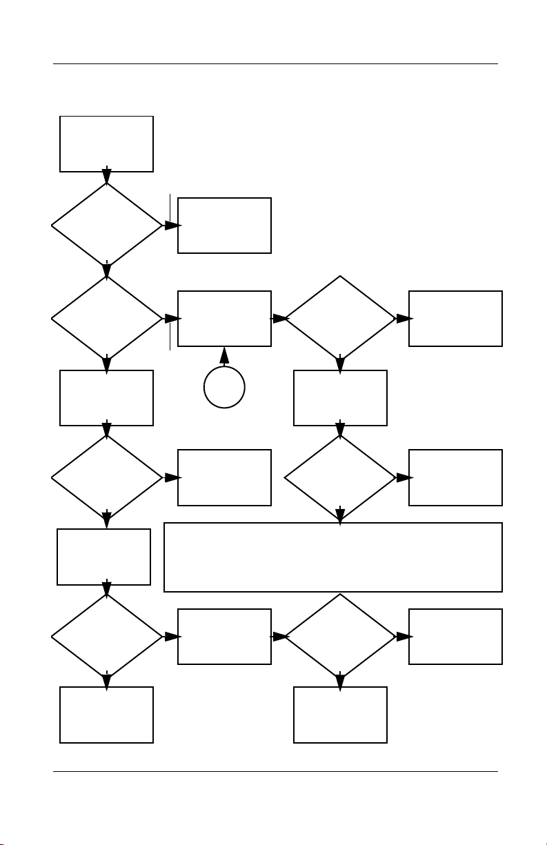
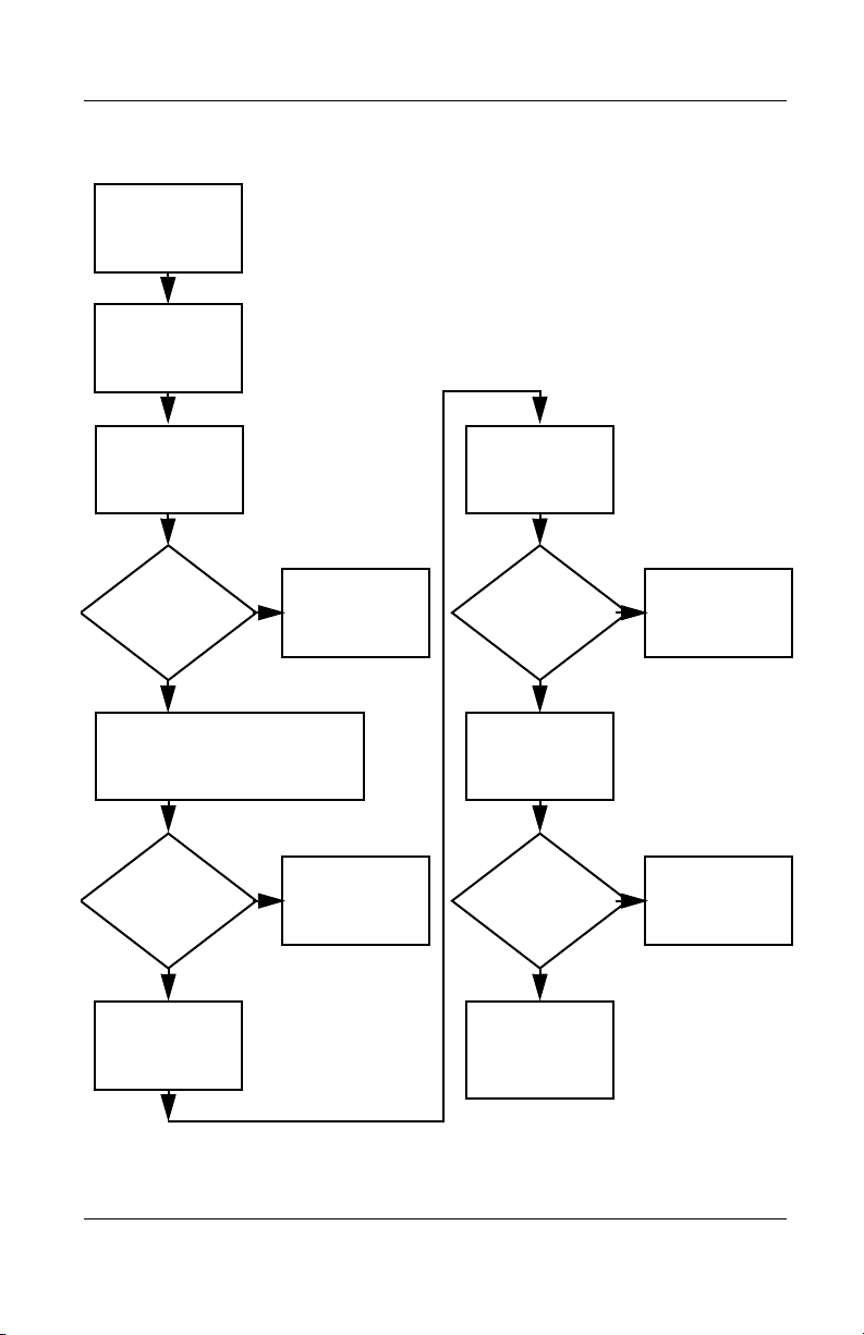
Flowchart 2.1 - Initial Troubleshooting
Begin
troubleshooting.
N
Troubleshooting
Is there
power?
Y
Beeps,
LEDs, or error
messages?
Y
Is there video?
(no boot)
Y
Is the OS
loading?
Y
Is there
sound?
Y
Flowchart 2.2,
No Power, Part 1.
N
LED board,
connections.
N
Flowchart 2.6,
No Video, Part 1.
N
Flowchart 2.9,
No OS Loading.
N
Flowchart 2.15,
No Audio.
Go to
Check
speaker
Go to
Go to
Go to
All drives
working?
Y
Keyboard/
pointing device
working?
Y
Connecting
to network
or modem?
Y
End
N
Flowchart 2.17,
Nonfunctioning
N
Flowchart 2.18,
Nonfunctioning
Keyboard,
or Flowchart 2.19,
Nonfunctioning
Pointing Device.
N
Flowchart 2.20,
No Network or
Connection.
Go to
Device.
Go to
Go to
Modem
Maintenance and Service Guide 2–11
Page 60

Troubleshooting
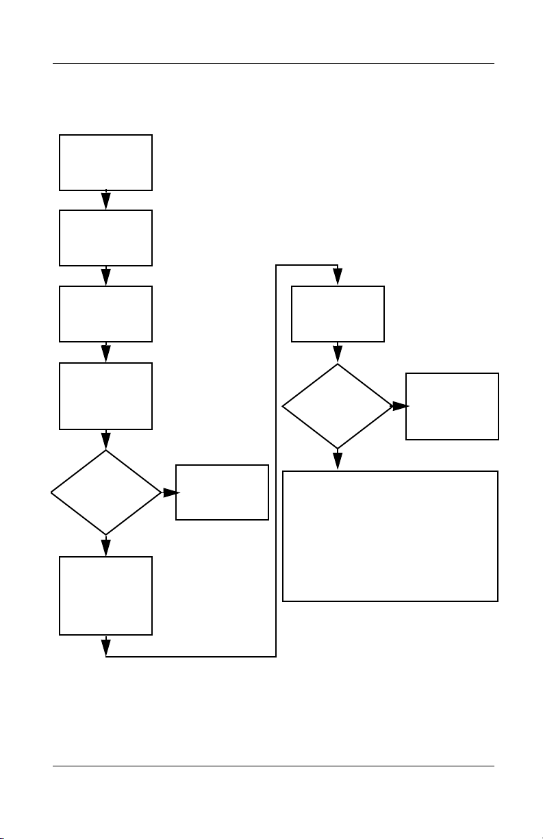
Flowchart 2.2 - No Power, Part 1
No power
(power LED
is off).
Remove from
docking station
(if applicable).
N
Power up
on battery
power?
*Reset
power.
Y
N
Power up
on AC
power?
*Reset
power.
Y
Y
Power up
in docking
station?
Done
N
1. Reseat the power cables in the docking
station and at the AC outlet.
2. Ensure that the AC power source is active.
3. Ensure that the power strip is working.
YN
Done
Power up
in docking
station?
N
Power up
on battery
power?
Go to
Flowchart 2.3,
No Power,
Part 2.
Y
N
Power up
on AC
power?
Go to
Flowchart 2.4,
No Power,
Part 3.
Y
*On some models there is a separate reset
button. On some models the computer may
be reset using the Standby switch and either
the lid switch or the main power switch.
Go to
Flowchart 2.8,
Nonfunctioning
Docking Station.
2–12 Maintenance and Service Guide
Page 61

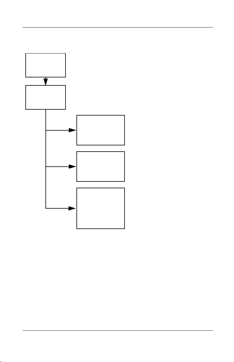
Flowchart 2.3 - No Power, Part 2
Continued from
Flowchart 2.2,
No Power, Part 1.
Visually check for
debris in battery
socket and clean if
necessary.
Y
Troubleshooting
Power on?
N
Check battery
by recharging,
moving it to
another computer,
or replacing it.
Power on?
Y
Done
Done
N
Replace
power supply
(if applicable).
N
Go to
Power on?
Flowchart 2.4,
No Power,
Part 3.
Y
Done
Maintenance and Service Guide 2–13
Page 62

Troubleshooting
Flowchart 2.4 - No Power, Part 3
Continued from
Flowchart 2.3,
No Power, Part 2.
Plug directly
into AC outlet.
Y
Power LED
on?
N
Reseat AC adapter
in computer and
at power source.
Power on?
N
Power outlet
active?
Y
Replace
power cord.
Power on?
Done
Y
Done
N
Try different
outlet.
Internal or
external AC
Internal
Flowchart 2.5,
No Power,
Y
Done
adapter?
Go to
Part 4.
External
Replace external
AC adapter.
N
Power on?
Y
Done
N
2–14 Maintenance and Service Guide
Page 63

Flowchart 2.5 - No Power, Part 4
Continued from
Flowchart 2.4,
No Power, Part 3.
Open
computer.
Troubleshooting
Loose or
damaged
parts?
N
Close
computer and
retest.
Power on?
Y
Done
Y
Reseat loose
components and
boards and
replace
damaged items.
N
Replace the following items (if applicable).
Check computer operation after each
replacement:
1. Internal DC-DC converter*
2. Internal AC adapter
3. Processor board*
4. System board*
*Replace these items as a set to prevent
shorting out among components.
Maintenance and Service Guide 2–15
Page 64
Troubleshooting
Flowchart 2.6 - No Video, Part 1
No video.
Docking
station
Stand-alone
or docking
station?
Go to
Flowchart 2.7,
No Video, Part 2.
*To change from internal to
external display, use the hotkey
combination.
Stand-alone
Y
Internal or
external
display*?
External
Adjust
brightness.
Internal
Y
Video OK? Done
N
Check for bent
pins on cable.
N
Video OK?
Adjust
brightness.
Video OK? Done
N
A
Press lid
switch to ensure
operation.
Y
Video OK?
Done
N
Replace the following one at a time. Test after each replacement.
1. Cable between notebook and computer display (if applicable)
2. Inverter board (if applicable)
3. Display
4. System board
N
Try
another
display.
Internal and
external
video OK?
Replace
system
board.
YY
Done
2–16 Maintenance and Service Guide
Done
Page 65
Flowchart 2.7 - No Video, Part 2
Continued from
Flowchart 2.6,
No Video, Part 1.
Remove
notebook from
docking station,
if connected.
Troubleshooting
Adjust
display
brightness.
N
Video OK?
No Video, Part 1.
Y
Check that notebook is properly
seated in docking station,
for bent pins on cable, and for
monitor connection.
Y
Video OK?
N
Adjust external
monitor display.
Go to “A” in
Flowchart 2.6,
Done
Check brightness
of external
monitor.
Video OK?
N
Try another
external
monitor.
Internal
and external
video OK?
N
Go to
Flowchart 2.8,
Nonfunctioning
Docking Station.
Y
Done
Y
Done
Maintenance and Service Guide 2–17
Page 66
Troubleshooting
Flowchart 2.8 - Nonfunctioning Docking Station
(if applicable)
Nonfunctioning
docking station.
Reseat power
cord in docking
station and
power outlet.
Check voltage
setting on
docking station.
Reset monitor
cable connector at
docking station.
Docking
station
operating?
N
Remove
notebook, reseat
all internal parts,
and replace any
damaged items in
docking station.
Reinstall
notebook into
docking station.
Y
Docking
station
operating?
Done
N
Y
Done
Replace the following docking station
components one at a time. Check
computer operation after each
replacement.
1. Power supply
2. I/O board
3. Backplane board
4. Switch box
5. Docking motor mechanism
2–18 Maintenance and Service Guide
Page 67
Troubleshooting
Flowchart 2.9 - No Operating System (OS) Loading
No OS
loading.*
Reseat power
cord in docking
station and
power outlet.
*Before beginning troubleshooting, always
check cable connections, cable ends, and
drives for bent or damaged pins.
No OS loading
from hard drive,
go to Flowchart 2.10,
No OS Loading from
Hard Drive, Part 1.
No OS loading
from diskette drive,
go to Flowchart 2.13,
No OS Loading from
Diskette Drive.
No OS loading
from CD- or
DVD-ROM drive,
go to Flowchart 2.14,
No OS Loading
from CD- or
DVD-ROM Drive.
Maintenance and Service Guide 2–19
Page 68
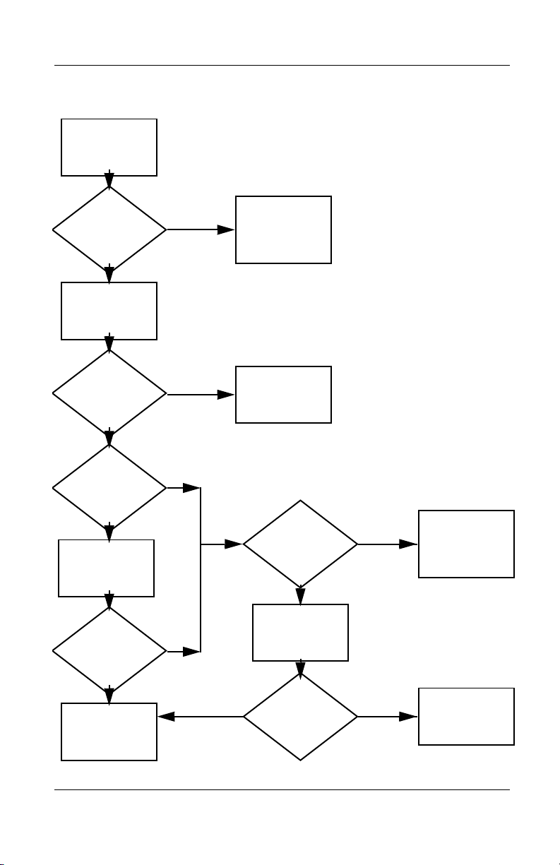
Troubleshooting
Flowchart 2.10 - No OS Loading from Hard Drive, Part 1
OS not
loading from
hard drive.
Nonsystem
disk message?
N
Reseat
external
hard drive.
OS loading?
N
Boot
from
CD?
Y
Check the setup
utility for correct
booting order.
Y
Go to
Flowchart 2.11,
No OS Loading
from Hard Drive,
Part 2.
Y
Done
N
N
Boot
from
diskette?
Y
Go to
Flowchart 2.13,
No OS
Loading from
Diskette Drive.
N
Boot
from
hard drive?
Y
Done
Change boot
priority through
the setup utility
and reboot.
Boot
from
hard drive?
N
Go to
Flowchart 2.17,
Nonfunctioning
Device.
Y
2–20 Maintenance and Service Guide
Page 69
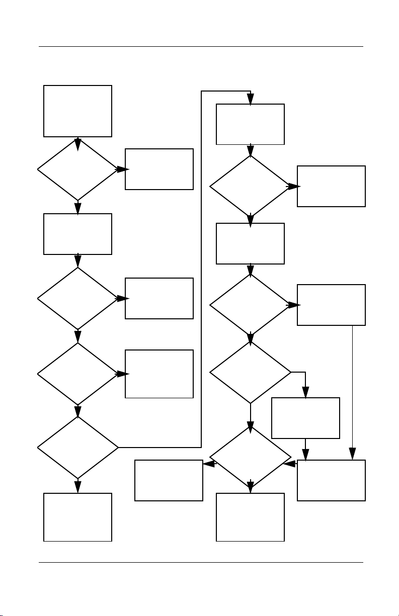
Troubleshooting
Flowchart 2.11 - No OS Loading from Hard Drive, Part 2
Continued from
Flowchart 2.10,
No OS Loading
from Hard Drive,
Part 1.
CD or
diskette in
drive?
Y
Remove
diskette and
reboot.
N
1. Replace hard
drive.
2. Replace system
board.
N
Reseat
hard drive.
Hard drive
accessible?
Run FDISK.
Y
Done
Boot
from
hard drive?
N
Boot
from diskette
drive?
Y
Hard drive
accessible?
Y
Go to
Flowchart 2.12,
No OS Loading
from Hard Drive,
Part 3.
Y
N
Flowchart 2.13,
No OS Loading
N
Done
Go to
from Diskette
Drive.
Done
Hard drive
partitioned?
Y
Hard drive
formatted?
Y
Y
Computer
booted?
Go to
Flowchart 2.12,
No OS Loading
from Hard Drive,
Part 3.
N
Create partition,
then format hard
drive to bootable
C:\ prompt.
N
Format hard drive
and bring to
a bootable
C:\ prompt.
Load OS using
Restore CD
(if applicable).
N
Maintenance and Service Guide 2–21
Page 70
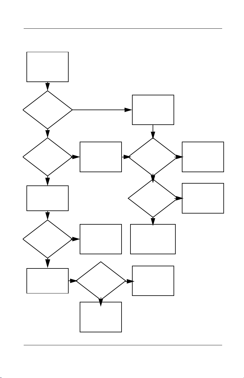
Troubleshooting
Flowchart 2.12 - No OS Loading from Hard Drive, Part 3
Continued from
Flowchart 2.11,
No OS Loading
from Hard Drive,
Part 2.
N
System
files on hard
drive?
Y
Virus
on hard
drive?
N
Run SCANDISK
and check for
bad sectors.
Can bad
sectors
be fixed?
Y
Fix bad
sectors.
Install OS
and reboot.
Y
Clean virus.
OS
loading from
hard drive?
Y
Done
N
Y
Diagnostics
on diskette?
Replace
hard drive.
N
N
Replace
hard drive.
Run diagnostics
and follow
recommendations.
N
Boot from
hard drive?
Replace
hard drive.
Y
Done
2–22 Maintenance and Service Guide
Page 71
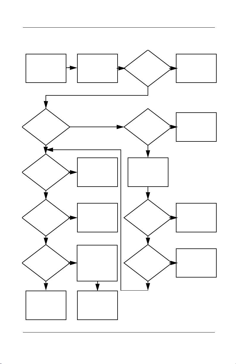
Troubleshooting
Y
Flowchart 2.13 - No OS Loading from Diskette Drive
OS not loading
from
diskette drive.
Nonsystem
disk message?
Boot
from another
device?
Y
Diskette
drive enabled
in the setup
utility?
Y
Y
N
N
Reseat
diskette drive.
Go to
Flowchart 2.17,
Nonfunctioning
Device.
Enable drive
and cold boot
computer.
OS
loading?
N
Bootable
diskette
in drive?
YN
Check diskette
for system files.
Try different
diskette.
Nonsystem
disk error?
N
Done
N
Install bootable
diskette and
reboot computer.
Y
1. Replace
diskette drive.
2. Replace system
board.
Y
Diskette
drive boot
order?
Change boot
priority using
the setup utility.
Maintenance and Service Guide 2–23
Clear CMOS.
Refer to
Section 1.3,
“Clearing a
Password,” for
instructions.
Go to
Flowchart 2.17,
Nonfunctioning
Device.
OS
loading?
NN
Y
Done
Page 72
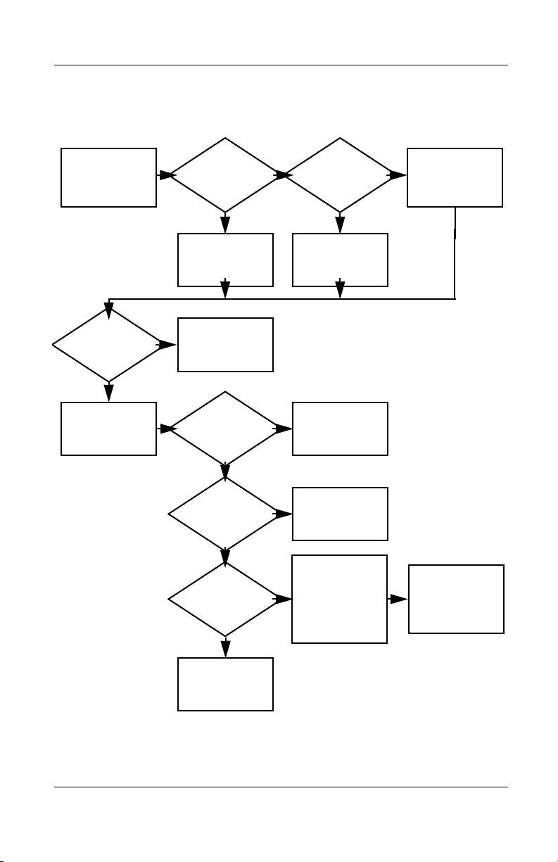
Troubleshooting
Y
N
Flowchart 2.14 - No OS Loading from CD- or
DVD-ROM Drive
No OS
loading from
CD- or
DVD-ROM Drive.
Boots from
CD or DVD?
N
Reseat
drive.
N
Y
N
Y
Disc
in drive?
Install
bootable disc.
Done
Boots from
CD or DVD?
Booting
from another
device?
Y
Y
N
Bootable
disc in
drive?
Try another
bootable disc.
Done
Go to
Flowchart 2.17,
Nonfunctioning
Device.
Install bootable
disc and
reboot
computer.
Clear CMOS.
Y
Booting
order
correct?
N
Correct boot
order using
the setup utility.
2–24 Maintenance and Service Guide
Refer to
Section 1.3,
“Clearing a
Password,” for
instructions.
Go to
Flowchart 2.17,
Nonfunctioning
Device.
Page 73
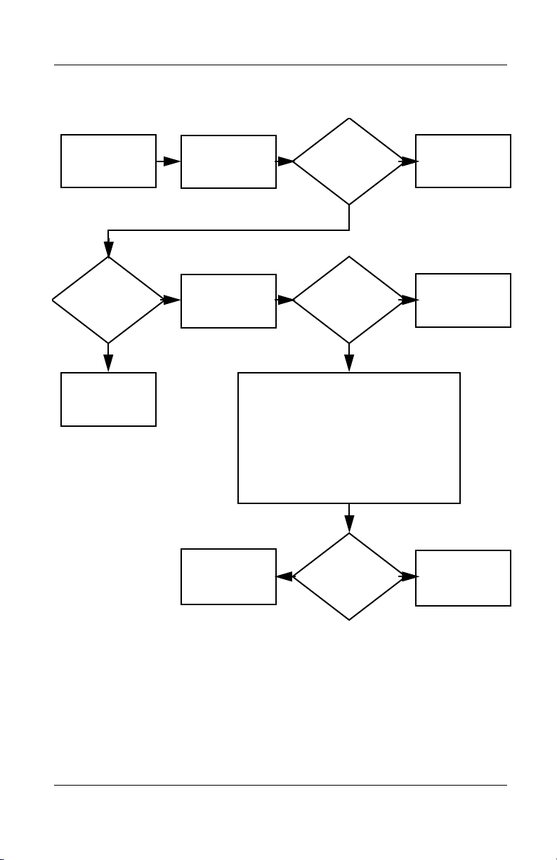
Flowchart 2.15 - No Audio, Part 1
Y
Troubleshooting
No audio.
Notebook in
docking station
(if applicable)?
N
Go to
Flowchart 2.16,
No Audio, Part 2.
Y
Turn up audio
internally or
externally.
Undock
Replace the following docking station
components one at a time as applicable.
Check after each change.
1. Reseat docking station audio cable.
2. Replace audio cable.
3. Replace speaker.
4. Replace docking station audio board.
5. Replace backplane board.
6. Replace I/O board.
Go to
Flowchart 2.17,
Nonfunctioning
Device.
Audio?
Done
N
N
Internal
audio?
Go to
Flowchart 2.16,
No Audio, Part 2.
Y
Y
Audio?
Done
N
Maintenance and Service Guide 2–25
Page 74

Troubleshooting
Flowchart 2.16 - No Audio, Part 2
Continued from
Flowchart 2.15,
No Audio, Part 1.
N
Audio
driver in OS
configured?
Reload
audio drivers.
Y
N
Correct
drivers for
application?
Load drivers and
set configuration
in OS.
Y
Connect to
external
speaker.
Replace audio
board and
Audio?
YN
speaker
connections in
notebook
(if applicable).
1. Replace internal speakers.
2. Replace audioboard(if applicable).
3. Replace system board.
Audio? Done
YN
2–26 Maintenance and Service Guide
Page 75

Flowchart 2.17 - Nonfunctioning Device
Nonfunctioning
device.
Reseat
device.
Unplug the nonfunctioning device
from the notebook and inspect cables
and plugs for bent or broken pins or
Clear
CMOS.
other damage.
Y
Any physical
device detected?
N
Troubleshooting
Fix or
replace
broken item.
Reattach device.
Close notebook,
plug in power,
and reboot.
N
Device
boots
properly?
Y
Done
Maintenance and Service Guide 2–27
Possible bad
hard drive.
Replace drive.
Possible bad NIC.
Replace card. If
integrated NIC,
replace system
board.
Possible bad
diskette drive.
Replace drive.
Go to
Flowchart 2.9,
No OS Loading.
Device
boots
properly?
Y
Done
N
Page 76

Troubleshooting
Flowchart 2.18 - Nonfunctioning Keyboard
Keyboard
not operating
properly.
Connect notebook
to good external
keyboard.
N
External
device
works?
Y
Reseat internal
keyboard
connector
(if applicable).
Replace
system
board.
N
OK?
Replace internal
keyboard or
cable.
Y
Y
Done Done
OK?
N
Replace
system
board.
2–28 Maintenance and Service Guide
Page 77

Troubleshooting
Flowchart 2.19 - Nonfunctioning Pointing Device
Pointing device
not operating
properly.
Connect notebook
to good external
pointing device.
N
External
device
works?
Replace
system
board.
Y
Reseat internal
pointing device
connector
(if applicable).
N
OK?
Replace internal
pointing device
or cable.
Y
Y
Done Done
OK?
N
Replace
system
board.
Maintenance and Service Guide 2–29
Page 78

Troubleshooting
Flowchart 2.20 - No Network or Modem Connection
No network
or modem
connection.
N
Network
or modem jack
active?
Y
Digital
line?
N
NIC/modem
configured
in OS?
Y
Disconnect all
power from
the notebook
and open.
Reseat
NIC/modem
(if applicable).
Replace jack or
Y
to nondigital
N
drivers and
reconfigure.
have jack
activated.
Connect
line.
Reload
N
NIC/modem
(if applicable).
N
OK?
Replace
OK?
Y
Done
Y
Done
Replace
system
board.
2–30 Maintenance and Service Guide
Page 79

Illustrated Parts Catalog
This chapter provides an illustrated parts breakdown and a
reference for spare part numbers and option part numbers.
3.1 Serial Number Location
When ordering parts or requesting information, provide the
notebook serial number and model number located on the bottom
of the notebook (Figure 3-1).
3
Figure 3-1. Serial Number Location
Maintenance and Service Guide 3–1
Page 80
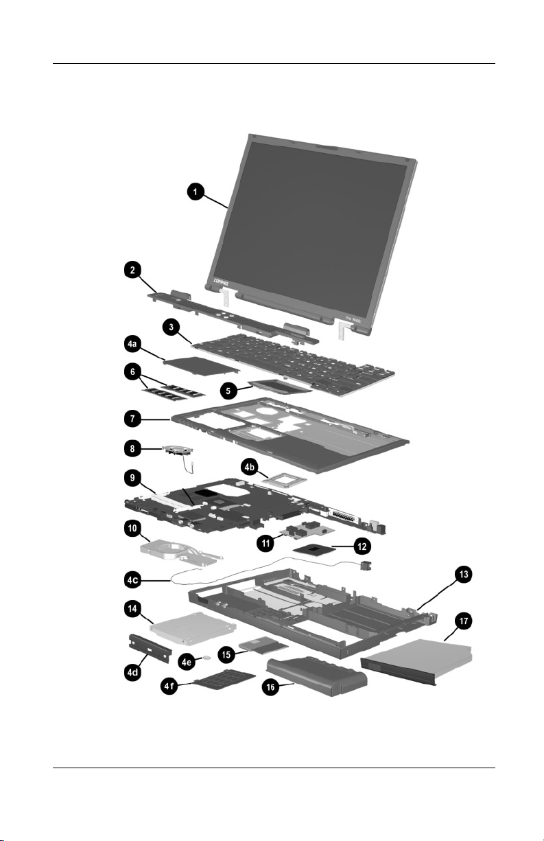
Illustrated Parts Catalog
3.2 Notebook System Major Components
Figure 3-2. Notebook System Major Components
3–2 Maintenance and Service Guide
Page 81

Illustrated Parts Catalog
Table 3-1
Spare Parts: Notebook System Major Components
Spare Part
Item Description
1 Displays
For use with Evo Notebook N620c models only
14.1-inch, SXGA+, CTFT 319733-001
For use with Evo Notebook N610c models only:
14.1-inch, SXGA+, CTFT
14.1-inch, XGA, CTFT
For use with Evo Notebook N600c models only:
14.1-inch, SXGA+, CTFT
14.1-inch, XGA, CTFT
2 Switch cover 241438-001
3 Keyboard with pointing stick (for use with
Dual Stick models)
Number
291261-001
291262-001
241433-001
241434-001
Arabic
Bosnia-
Herzegovina/
Croatia/
Slovenia/
Yugoslavia
Brazilian
Czech
Danish
European
French
French
Canadian
German
Greek
Hebrew
Hungarian
241427-171
241427-B41
241427-201
241427-221
241427-081
241427-021
241427-051
241427-121
241427-041
241427-151
241427-BB1
241427-211
International
Italian
Japanese
Korean
Latin American
Spanish
Norwegian
Portuguese
Russian
Slovakian
Spanish
Swedish/Finnish
Swiss
Taiwanese
Tu r ki s h
U.K. English
U.S. English
241427-002
241427-061
241427-291
241427-AD1
241427-161
241427-091
241427-131
241427-251
241427-231
241427-071
241427-101
241427-111
241427-AB1
241427-141
241427-031
241427-001
Maintenance and Service Guide 3–3
Page 82

Illustrated Parts Catalog
Notebook System Major Components (continued)
3–4 Maintenance and Service Guide
Page 83

Illustrated Parts Catalog
Table 3-1
Spare Parts: Notebook System Major Components
Item Description
3 Keyboard without pointing stick (for use with
TouchPad models)
(Continued)
Spare Part
Number
Arabic
Bosnia-
Herzegovina/
Croatia/
Slovenia/
Yugoslavia
Brazilian
Czech
Danish
European
French
French
Canadian
German
Greek
Hebrew
Hungarian
241428-171
241428-B41
241428-201
241428-181
241428-221
241428-021
241428-051
241428-121
241428-041
241428-151
241428-BB1
241428-211
International
Italian
Japanese
Korean
Latin American
Spanish
Norwegian
Portuguese
Russian
Slovakian
Spanish
Swedish/Finnish
Swiss
Taiwanese
Tu r ki s h
U.K. English
U.S. English
241428-002
241428-061
241428-291
241428-AD1
241428-161
241428-091
241428-131
241428-251
241428-231
241428-071
241428-101
241428-111
241428-AB1
241428-141
241428-031
241428-001
Maintenance and Service Guide 3–5
Page 84

Illustrated Parts Catalog
Notebook System Major Components (continued)
3–6 Maintenance and Service Guide
Page 85

Illustrated Parts Catalog
Table 3-1
Spare Parts: Notebook System Major Components
Item Description
Miscellaneous Plastics Kit 241439-001
(Continued)
Spare Part
Number
4a
4b
4c
4d
4e
4f
5 TouchPad components
Memory expansion compartment cover (on Evo Notebook N620c and
N610c models)
Mini PCI compartment cover (on Evo Notebook N600c models)
Processor bracket
Modem cable
Hard drive bezel
Disk cell RTC battery
Mini PCI compartment cover (on Evo Notebook N620c and
N610c models)
Memory expansion compartment cover (on Evo Notebook
N600c models)
Not illustrated:
MultiPort module cover
Notebook feet
PC Card slot space savers
RJ-11 cover
For use with Evo Notebook N620c models only:
TouchButton with pointing stick buttons
(for use with Dual Stick models)
For use with Evo Notebook N610c models only:
TouchPad (for use with TouchPad models)
TouchButton with pointing stick buttons
(for use with Dual Stick models)
For use with Evo Notebook N600c models only:
TouchPad (for use with TouchPad models)
TouchButton with pointing stick buttons
(for use with Dual Stick models)
319772-001
253658-001
252434-001
135227-001
159530-001
Maintenance and Service Guide 3–7
Page 86

Illustrated Parts Catalog
Notebook System Major Components (continued)
3–8 Maintenance and Service Guide
Page 87

Illustrated Parts Catalog
Table 3-1
Spare Parts: Notebook System Major Components
Item Description
6 Memory expansion boards
266 MHz, 2DM (for Evo Notebook N620c
models only)
1024 MB
768 MB
512 MB
384 MB
256 MB
133 MHz (for Evo Notebook N610c models only)
512 MB
256 MB
128 MB
64 MB
100 MHz (for Evo Notebook N600c models only)
512 MB
256 MB
128 MB
(Continued)
Spare Part
Number
301576-001
301575-001
301574-001
301572-001
301571-001
238879-001
212683-001
212682-001
212681-001
280875-001
280874-001
280873-001
7 Top covers
For use with Evo Notebook N620c and N610c
models only
For use with Evo Notebook N600c models only
8 Fans
For use with Evo Notebook N620c and N610c
models only
For use with Evo Notebook N600c models only
291264-001
241436-001
291266-001
255528-001
Maintenance and Service Guide 3–9
Page 88
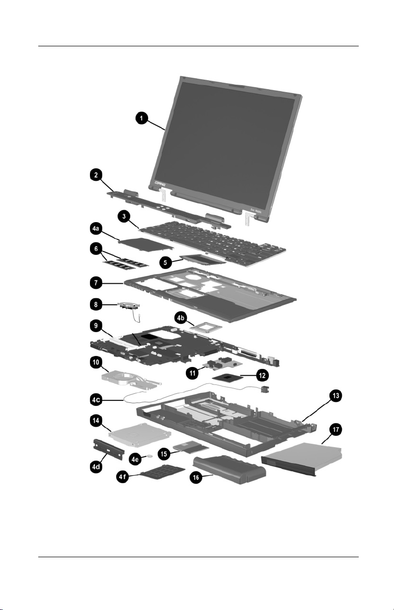
Illustrated Parts Catalog
Notebook System Major Components (continued)
3–10 Maintenance and Service Guide
Page 89

Illustrated Parts Catalog
Table 3-1
Spare Parts: Notebook System Major Components
Item Description
9 System boards
(Continued)
Spare Part
Number
For use with Evo Notebook N620c models only
For use with Evo Notebook N610c models only
For use with Evo Notebook N600c models only:
Mobile Intel Pentium III processor 1.066 GHz-M
Mobile Intel Pentium III processor 866 MHz-M
10 Heat sink 303103-001
11 DC-DC converter boards
For use with Evo Notebook N620c models only
For use with Evo Notebook N610c models only
For use with Evo Notebook N600c models only
12 Processors
For use only with Evo Notebook N620c models
Intel Pentium-M 1.6 GHz
Intel Pentium-M 1.5 GHz
Intel Pentium-M 1.4 GHz
Intel Pentium-M 1.3 GHz
For use only with Evo Notebook N610c models
Mobile Intel Pentium 4 2.0 GHz
Mobile Intel Pentium 4 1.8 GHz
Mobile Intel Pentium 4 1.7 GHz
Mobile Intel Pentium 4 1.6 GHz
Intel Celeron 1.5 GHz 309420-001
319778-001
291581-001
241430-001
241432-001
319635-001
291263-001
241435-001
319777-001
319776-001
319775-001
319774-001
303282-001
291269-001
291268-001
291267-001
13 Base enclosures
For use with Evo Notebook N620c models only
For use with Evo Notebook N610c models only
For use with Evo Notebook N600c models only
310547-001
291265-001
241437-001
Maintenance and Service Guide 3–11
Page 90

Illustrated Parts Catalog
Notebook System Major Components (continued)
3–12 Maintenance and Service Guide
Page 91

Illustrated Parts Catalog
Table 3-1
Spare Parts: Notebook System Major Components
Item Description
14 Hard drives
For use with Evo Notebook N620c models only:
60 GB, 5400 RPM
60 GB, 4200 RPM
40 GB, 5400 RPM
40 GB, 4200 RPM
For use with Evo Notebook N610c models only:
40 GB
30 GB
20 GB
For use with Evo Notebook N600c models only:
30 GB
20 GB
15 GB
10 GB
(Continued)
Spare Part
Number
309475-001
309474-001
309473-001
309472-001
265495-001
257660-001
235540-101
217096-001
235421-001
241429-001
217094-001
15 Mini PCI communications boards
Type III mini PCI combination 56-Kbps modem/NIC
Type III mini PCI combination 56-Kbps modem/
3DES NIC
Type III mini PCI 56-Kbps modem
16 Battery packs (6-cell, Li ion) 232633-001
230338-001
230339-001
230337-001
and
301952-001
Maintenance and Service Guide 3–13
Page 92

Illustrated Parts Catalog
Notebook System Major Components (continued)
3–14 Maintenance and Service Guide
Page 93

Illustrated Parts Catalog
Table 3-1
Spare Parts: Notebook System Major Components
Item Description
17 Media Bay devices
For use with all Evo Notebook N620c, N610c, and
N600c models:
Diskette drive
24X Max CD-ROM drive
8X Max CD-RW drive
8X Max DVD-ROM drive
DVD/CD-RW combination drive
2X Max SuperDisk LS120 drive
IOmega 250-MB ZIP drive
MultiBay battery pack, 6 cell
MultiBay battery pack, 3.2 ah
For use with Evo Notebook N620c and N610c
models only:
16X Max CD-RW drive
24X Max DVD/CD-RW combination drive
(Continued)
Spare Part
Number
135233-001
228746-001
and
228746-001
153992-001
173949-001
238878-001
201274-001
218683-001
100680-001
280876-001
274419-001
274420-001
Maintenance and Service Guide 3–15
Page 94

Illustrated Parts Catalog
3.3 Miscellaneous Plastics Kit Components
Figure 3-3 Miscellaneous Plastics Kit Components
3–16 Maintenance and Service Guide
Page 95

Illustrated Parts Catalog
Table 3-2
Miscellaneous Plastics Kit Components
Spare Part Number 241439-001
Item Description
1 Memory expansion compartment cover (Evo Notebook N620c and
N610c models)
Mini PCI compartment cover (Evo Notebook N600c models)
2 Mini PCI compartment cover (Evo Notebook N620c and
N610c models)
Memory expansion compartment cover (Evo Notebook N600c models)
3 PC Card slot space savers
4 Processor bracket
5 Hard drive bezel
6 MultiPort module cover
7 Disk cell RTC battery
8 Notebook feet
9 Modem cable
10 RJ-11 connector cover
11 Media Bay space saver
Maintenance and Service Guide 3–17
Page 96
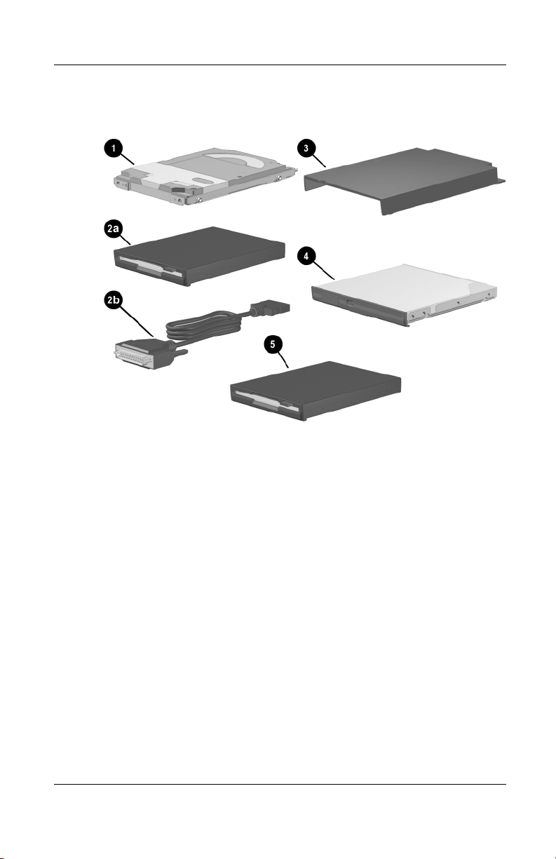
Illustrated Parts Catalog
3.4 Mass Storage Devices
Figure 3-4. Mass Storage Devices
3–18 Maintenance and Service Guide
Page 97

l
Item Description
1 Hard drives
For use with Evo Notebook N620c models only:
60 GB, 5400 RPM
60 GB, 4200 RPM
40 GB, 5400 RPM
40 GB, 4200 RPM
For use with Evo Notebook N610c models only:
40 GB
30 GB
20 GB
For use with Evo Notebook N600c models only:
30 GB
20 GB
15 GB
10 GB
Illustrated Parts Catalog
Table 3-3
Mass Storage Devices
Spare Part
Number
309475-001
309474-001
309473-001
309472-001
265495-001
257660-001
235540-101
217096-001
235421-001
241429-001
217094-001
2a
2b
3 External Media Bay cradle
Diskette drive
External diskette drive cable
External Media Bay USB cradle
External Media Bay USB cradle cable
External Media Bay cradle AC adaptor
External Media Bay cradle plugs
135233-001
135232-001
218685-001
280879-001
287693-001
287694-001
287695-001
Maintenance and Service Guide 3–19
Page 98
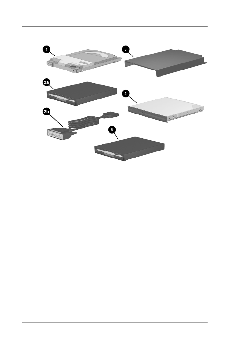
Illustrated Parts Catalog
Mass Storage Devices
3–20 Maintenance and Service Guide
(continued)
Page 99

l
Mass Storage Devices
Item Description
4 Optical drives
For use with all Evo Notebook N620c, N610c,
and N600c models:
Diskette drive
24X Max CD-ROM drive
8X Max CD-RW drive
8X Max DVD-ROM drive
DVD/CD-RW combination drive
2X Max SuperDisk LS120 drive
Iomega 250-MB ZIP drive
MultiBay battery pack, 6 cell
MultiBay battery pack, 3.2 ah
For use with Evo Notebook N620c and N610c
models only:
16X Max CD-RW drive
24X Max DVD/CD-RW combination drive
Illustrated Parts Catalog
Table 3-3
(Continued)
Spare Part
Number
135233-001
228746-001
and
228746-001
153992-001
173949-001
238878-001
201274-001
218683-001
100680-001
280876-001
274419-001
274420-001
5 Iomega 250-MB ZIP drive
2X Max SuperDisk LS120 drive
218683-001
201274-001
Maintenance and Service Guide 3–21
Page 100

Illustrated Parts Catalog
3.5 Miscellaneous
Tabl e 3-4
Spare Parts: Miscellaneous (not illustrated)
Spare Part
Description
AC adaptors
90-Watt AC adapter power supply
65-Watt AC adapter power supply
50-Watt AC adapter power supply
Bluetooth wireless communication MultiPort module 230336-001
Logo kit 304204-001
Modems
Number
239705-001
239704-001
120765-001
Type III mini PCI combination 56-Kbps modem/NIC
Type III mini PCI combination 56-Kbps modem/3DES NIC
Type III mini PCI 56-Kbps modem
Modem adapters
Czech
German
Hungarian
Norwegian
Swiss
Modem cable 234962-001
Modem cable adapters
Australian
Belgian
French
3–22 Maintenance and Service Guide
230338-001
230339-001
230337-001
234963-221
236432-041
234963-211
234963-091
198294-111
304398-011
304398-181
304398-051
 Loading...