

Page 1

Netelligent 2724/2824
Dual-Speed Hubs
User Guide
©1997 Compaq Computer Corporation.All rights reserved.
Compaq Registered U.S.Patent and Trademark Office.
Company and product names mentioned herein may be
trademarks and/or registered copyright and trademarks of
their respective companies.
Page 2

. . . . . . . . . . . . . . . . . . . . . . . . . . . . .
NOTICE
The information in this publication is subject to change without notice.
COMPAQ COMPUTER CORPORATION SHALL NOT BE LIABLE FOR TECHNICAL OR
EDITORIAL ERRORS OR OMISSIONS CONTAINED HEREIN, NOR FOR INCIDENTAL OR
CONSEQUENTIAL DAMAGES RESULTING FROM THE FURNISHING, PERFORMANCE, OR
USE OF THIS MATERIAL.
This publication contains information protected by copyright. No part of this publication may be
photocopied or reproduced in any form without prior written consent from Compaq Computer
Corporation.
The software described in this guide is furnished under a license agreement or non-disclosure agreement.
The software may be used or copied only in accordance with the terms of the agreement.
Product names mentioned herein may be trademarks and/or registered trademarks of their respective
companies.
1997 Compaq Computer Corporation.
All rights reserved. Printed in the U.S.A.
Compaq
Registered United States Patent and Trademark Office.
Netelligent is a trademark of Compaq Computer Corporation.
Compaq Netelligent 2724/2824 Dual-Speed Hub User Guide
First Edition (June 1997)
Part Number 299440-001
Page 3
. . . . . . . . . . . . . . . . . . . . . . . . . . . . .
v
Federal Communications Commission Notice
Part 15 of the Federal Communications Commission (FCC) Rules and Regulations has established
Radio Frequency (RF) emission limits to provide an interference-free radio frequency spectrum. Many
electronic devices, including computers, generat e RF energy incidental to their int ended function and
are, therefore, covered by these rules. These rules place comput ers and related peripheral devices into
two classes, A and B, depending upon their intended installation. Class A devices are those that may
reasonably be expected to be installed in a business or commercial environment . Class B devices are
those that may reasonably be expected to be installed in a residential environment (i.e., personal
computers). The FCC requires devices in both classes to bear a label indicating the interference
potential of the device as well as addit i onal opera ti ng i nst r ucti ons f or the us er.
The rating label on the device shows which clas s (A or B) the equipment falls into. Class B devices
have an FCC ID on the label. Class A devices do not have an FCC ID on the label . Once the class of
the device is determi ned, r ef er to t he f oll owing corr es ponding s tat em ent .
Connections to the serial COM port on this device must be made with shielded cables with metallic
RFI/EMI connector hoods in order to m ai nta in com pl ia nce with FCC Rules and Regulati ons.
NOTE:
If this equipment contains a Token Ring interface, this equipment is a Class A digital device
when the Token Ring interface is utilized.
Class A Equipment
This equipment has been tested and found to comply with the limits for a Class A digital device,
pursuant to Part 15 of the FCC Rules. These limits are designed to provide reasonable protection
against harmful interference when the equipment is operated in a commercial environment. This
equipment generates, us es, and can radiate radio frequency energy and, if not ins talled and used in
accordance with the instructions, m ay cause harmful interfer ence to radio communicati ons. Operation
of this equipment in a residential area is likely to cause harmful interference, in which case the user
will be required to correct the interference at personal expense.
Modifications
The FCC requires the user to be notifi ed t hat any changes or modifi cat ions made to t hi s device that are
not expressly approved by Compaq Computer Corporat ion may void t he user's author ity to operate the
equipment.
Compaq Netelligent 2724/2824 Dual-Speed Hub User Guide
Page 4

. . . . . . . . . . . . . . . . . . . . . . . . . . . . . .
vi
Canadian Notice
This Class A digital apparatus meets all requirements of the Canadian Interference-Causing Equipment
Regulations.
Avis Canadien
Cet appareil numérique de la classe A respecte toutes les exigences du Règlement sur le matériel
brouilleur du Canada.
European Union (EU) Notice
Products with the CE Marking comply with both the EMC Directive (89/336/EEC) and the Low Voltage
Directive (73/23/EEC) issued by the Commission of the European Community.
Compliance with these directives implies conformity to the following European Norms (in brackets are
the equivalent international standards):
■
EN55022 (CISPR 22) - Electromagnetic Interference
■
EN50082-1 (IEC801-2, IEC801-3, IEC801-4) - Electromagnetic Immunity
■
UL 1950, Third Edition; CAN/CSA C22.2 No. 950-95, July 1995; TUV Rheinland
EN 60950; and 1988 + A1/1990+A2/1991 - Product Safety
Page 5
. . . . . . . . . . . . . . . . . . . . . . . . . . . . .
v
Japanese Notice
Fiber Port Class 1 Classification
Compaq fiber ports have been tested in accordance with the IEC 825-1 test standard and found to meet
the Class 1, intrinsically eye-safe emitter classification.
Product Label
CLASS 1 LED
KLASSE 1 LED
The fiber ports on this product have been tested in accordance with the
IEC 825-1 Test Standard and found to meet the Class 1, intrinsically
eye-safe emitter classification.
Compaq Netelligent 2724/2824 Dual-Speed Hub User Guide
Page 6
. . . . . . . . . . . . . . . . . . . . . . . . . . . . . .
viii
Lithium Battery
The non-volatile RAM (NVRAM) chip on the motherboard of the Netelligent 2824 hub contains a nonreplaceable lithium battery. Only trained service personnel should dispose of this chip.
La puce mémoire non volatile contient une pile au lithium non remplaçable. L'élimination de cette
puce devrait être confieé à un per sonnel quali f i é.
Page 7

. . . . . . . . . . . . . . . . . . . . . . . . . . . . .
Contents
Chapter 1
Overview
Features.........................................................................................................................1-2
Package Contents..........................................................................................................1-4
Hub Components ..........................................................................................................1-5
RJ-45 Ports ............................................................................................................1-5
Smart Uplink Slot..................................................................................................1-5
LED Indicators ......................................................................................................1-6
Serial COM Port.................................................................................................... 1-8
Host/Target DIP Switch ........................................................................................1-9
Managed/Unmanaged DIP Switch ......................................................................1-10
Internal 10/100 Switch Disable DIP Switch........................................................1-10
10 ONLY - 10/100 Switch ..................................................................................1-10
10 MDI - 10/100 MDI-X Switch.........................................................................1-11
Segmentation ..............................................................................................................1-12
ix
Chapter 2
Planning Installation
Installation Requirements.............................................................................................2-1
Environmental Requirements................................................................................2-1
Electrical Requirements.........................................................................................2-1
Spatial Requirements.............................................................................................2-2
Cable Requirements...............................................................................................2-2
System Planning Charts................................................................................................2-5
Compaq Netelligent 2724/2824 Dual-Speed Hub User Guide
Page 8

. . . . . . . . . . . . . . . . . . . . . . . . . . . . . .
x
Chapter 3
Installing the Hub
Mounting the Hub.........................................................................................................3-1
Attaching the Rubber Feet.....................................................................................3-1
Rack-Mounting the Hub........................................................................................3-1
Installing a Smart Uplink Module ................................................................................3-3
Inserting the Smart Uplink Module into the Smart Uplink Slot............................3-3
Connecting Cable..........................................................................................................3-5
Interconnecting Hubs....................................................................................................3-6
Connecting Power.......................................................................................................3-10
Disconnecting Power...........................................................................................3-11
Connecting to the Serial Port......................................................................................3-11
Chapter 4
Configuring the Hub for Management
Setting the IP Address Using VT100............................................................................4-1
Setting the IP Address Using a BOOTP Server............................................................4-7
Chapter 5
Managing the Hub
Management Features...................................................................................................5-1
Management Interface ..................................................................................................5-1
SNMP Management......................................................................................................5-3
Supported MIBs.....................................................................................................5-3
Supported Frame Types.........................................................................................5-3
IP Frame Types......................................................................................................5-4
IP Protocols ...........................................................................................................5-6
IPX Frame Type ....................................................................................................5-7
IPX Protocols.........................................................................................................5-9
SLIP Protocols.....................................................................................................5-10
Page 9

. . . . . . . . . . . . . . . . . . . . . . . . . . . . .
Traps.................................................................................................................... 5-11
RMON Support...........................................................................................................5-13
Statistics Group....................................................................................................5-13
History Group......................................................................................................5-14
Alarm Group........................................................................................................5-15
Event Group.........................................................................................................5-16
Firmware Updates.......................................................................................................5-17
Download Problems ............................................................................................5-18
Parameters Stored in NVRAM...................................................................................5-19
Compaq Specific Parameters......................................................................................5-20
Appendix A
Specifications
Physical........................................................................................................................A-1
Electrical...................................................................................................................... A-1
Environmental..............................................................................................................A-1
xi
Appendix B
Using the VT100 Interface
Connecting the Hub for VT100................................................................................... B-1
Setting Up the Communications Program.................................................................. B-1
Starting the VT100 Interface....................................................................................... B-2
Basic Update Fields.............................................................................................. B-4
VT100 Management Options....................................................................................... B-5
Displaying a Data Screen............................................................................................. B-6
Navigating the VT100 Screens.................................................................................... B-6
Viewing System Information....................................................................................... B-8
Viewing the Management Agent Configuration........................................................ B-10
Viewing Port Statistics .............................................................................................. B-12
Viewing the Stack Configuration .............................................................................. B-13
Viewing and Editing the Backup Port Configuration................................................ B-15
Compaq Netelligent 2724/2824 Dual-Speed Hub User Guide
Page 10

. . . . . . . . . . . . . . . . . . . . . . . . . . . . . .
xii
Changing the Password.............................................................................................. B-17
Downloading Firmware............................................................................................. B-19
Setting Up the Serial Port.......................................................................................... B-21
Configuring User Access........................................................................................... B-23
Configuring IP User Access............................................................................... B-24
Configuring IPX User Access ............................................................................ B-28
Logging Out of the Management Session................................................................. B-30
Index
Page 11

. . . . . . . . . . . . . . . . . . . . . . . . . . . . .
1-1
Chapter 1
Overview
The Netelligent 2724 and 2824 Dual-Speed hubs feature a 10Base-T and a
100Base-TX repeater in each unit connected by an internal two-port 10/100
Mb/s switch. Each of the hubs’ 24 RJ-45 ports automatically detects and adjusts
to 10 Mb/s or 100 Mb/s port connection speeds. This makes the hub a perfect
solution for networks migrating from 10 Mb/s to 100 Mb/s, allowing you to
move from 10 Mb/s to 100 Mb/s speeds on a port-by-port basis. The 100 Mb/s
repeater is a 100Base-TX Class I repeater.
The 2824 hub is a managing hub, which means it contains a built-in
management agent.
The 2724 hub is a manageable hub, which means it does not contain a
management agent but can be managed by a hub that does contain a
management agent (2624 or 2824 hub, provided they are running v2.0 or higher
management firmware). To be managed by a managing hub, the 2724 must be
connected to a managing hub’s connectors on its back panel. Up to five hubs
(one managing 2824 or 2624 and four manageable 2524 or 2724) can exist in a
single stack for a total of up to 125 ports (with SUMs installed).
Compaq Netelligent 2724/2824 Dual-Speed Hub User Guide
Page 12

. . . . . . . . . . . . . . . . . . . . . . . . . . . . . .
Overview
1-2
Features
The 2724/2824 hub provides the following set of features:
24 RJ-45 ports allows 10 Mb/s or 100 Mb/s connections by autodetecting
the wire speed.
Stackable lets you stack up to five hubs (four manageable 2724 hubs and
one managing 2824 hub) for up to 125 workstation connections. You can also
interconnect the 2724/2824 hubs with Netelligent 2524/2624 hubs.
Host/Target Design allows manageable hubs (Model 2724) to be managed
by a single managing hub (Model 2824)
24 Bi-Colored LED Indicators show port activity, port link, and port
disable/auto partition; other LEDs show collisions, the power supply status, and
the management status of the hub and the mode (10 or 100).
Backup Ports provide redundant port connections for mission-critical
applications (for example, order entry PCs connected to a file server).
Intrusion Detection provides a method of preventing unauthorized stations
from transmitting on the network.
Field-Upgradable Firmware lets you upgrade the 2824 hub firmware using
XMODEM and TFTP downloads via the BOOTP/TFTP sequence, the VT100
interface, or through SNMP. VT100 and SNMP can occur through both in-band
and out-of-band (SLIP) connections.
4-group RMON (Groups 1, 2, 3 & 9) allows remote monitoring and
gathering of network statistics without generating network traffic.
Compaq Netelligent Management Software provides an easy-to-use
graphical interface for managing the hub.
SNMP management over IP and IPX lets you monitor and manage the
hub via any industry-standard SNMP application, such as Compaq Netelligent
Management Software (provided at no extra charge with each unit).
VT100 interface allows out-of-band (serial port) and in-band (Telnet)
management for setting numerous configuration parameters.
Page 13

. . . . . . . . . . . . . . . . . . . . . . . . . . . . .
Rack Mount Kit lets you install the hub in a standard EIA 19-inch
equipment rack.
10/100 Switch Enable/Disable lets you enable or disable the internal 10/100
switch if the network uses an external bridge or router.
Multicast/Broadcast Filtering allows the hub to forward or block multicast
and broadcast packets independently on both the 10 and 100 Mb/s segments.
Statistics Separate statistics, similar to those available on the 10 and 100
Mb/s repeater ports, are available for both the 10 and 100 Mb/s ports on the
2-port 10/100 switch.
Smart Uplink Module Support allows the 2724/2824 hub to uplink to
another 2724/2824 hub to overcome the single repeater hop restriction for
Class I 100Base-T repeaters.
IP/IPX Autodiscovery allows the hub to be autodiscovered by network
management platforms such as Novell ManageWise, HP OpenView, SunNet
Manager, IBM NetView 6000.
1-3
Fast Ethernet Wiring Standards ensures compatibility with all types of
UTP cabling.
Three-Year Limited Warranty
Compaq Netelligent 2724/2824 Dual-Speed Hub User Guide
Page 14
. . . . . . . . . . . . . . . . . . . . . . . . . . . . . .
1-4 Overview
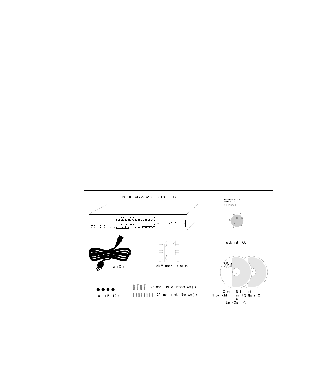
Package Contents
Before you start to install the hub, verify that this package contains the
following items:
■
Netelligent 2724 or 2824 Dual-Speed Hub
■
AC power cord
■
Rack-mounting kit (two mounting brackets, eight 3/8-inch bracket
screws, and four 1/2-inch rack-mount screws)
■
Four adhesive-backed rubber feet
■
Compaq Netelligent Management Software
■
Compaq Netelligent 2724/2824 Dual-Speed Hub Quick Install Guide
■
Compaq Netelligent 2724/2824 Dual-Speed Hub User Guide CD
■
Safety compliance guide
■
Registration card
Figure 1-1.
P
ackage Contents
Page 15
. . . . . . . . . . . . . . . . . . . . . . . . . . . . .
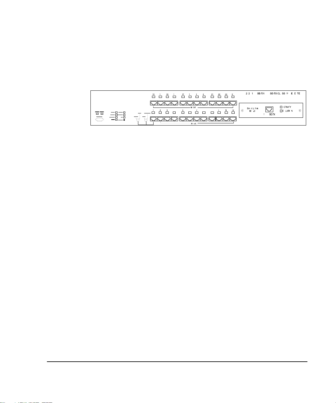
Hub Components
This section provides an overview of the hub's components including the LED
indicators, RJ-45 ports, and fiber ports. Figure 1-2 shows the hub’s front panel.
1-5
Figure 1- 2.
RJ-45 Ports
The hub’s RJ-45 ports allow connections to UTP cabling to workstations and
servers in a 10Base-T or 100Base-TX network. The hub automatically detects
the wire speed and adjusts accordingly. You can force Port 1 to run at 10 Mb/s
by setting the 10 Mb/s ONLY / 10/100 switch on the front panel to 10 ONLY.
You can also use Port 1 as an uplink port by setting the MDI / MDI-X switch to
the MDI position. See “MDI / MDI-X Switch” and “10 Mb/s ONLY / 10/100
Switch” for more information.
Smart Uplink Slot
The Smart Uplink slot houses an optional Smart Uplink Module (SUM), which
serves as a connection point between hubs, hub stacks, and other manufacturers'
100Base-TX, 100Base-TX(SC), 100Base-TX(ST) hubs or stacks. Smart Uplink
modules let you extend your network without the usual repeater hop limitations
inherent with Class I repeaters.
2724/2824 Hub Front Panel with Smart Uplink Module Installed
Compaq Netelligent 2724/2824 Dual-Speed Hub User Guide
Page 16
. . . . . . . . . . . . . . . . . . . . . . . . . . . . . .
Overview
1-6
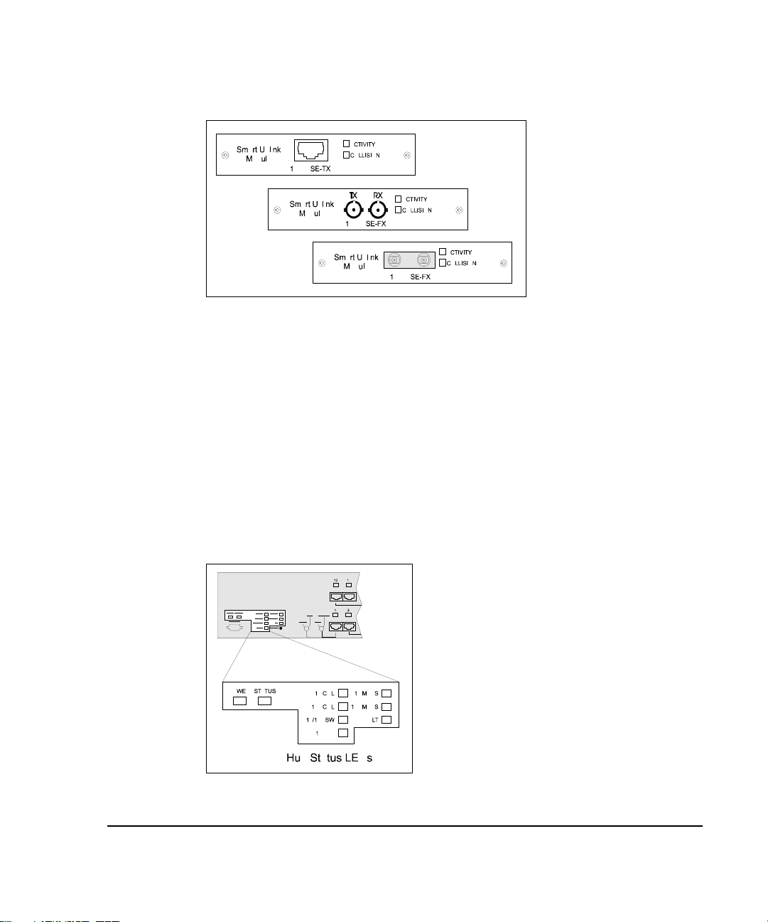
Figure 1- 3.
The SUM provides two status LEDs: activity and collision. The activity LED is
a solid green when the link is active and flashes green when there is activity on
the port. The collision LED flashes yellow when a collision is detected and
lights solid yellow when the port is disabled. The collision LED does not reflect
conditions at the SUM’s hub port, only at the external interface port.
LED Indicators
The LED panel of the 2724/2824 hub helps you monitor the hub’s operation.
When you power on a hub, it performs a power-on self test (POST) which lasts
about 1 minute. After the POST, all LEDs reflect the current operational modes
which are described in Table 1-1.
Smart Uplink Modules
Figure 1- 4.
Hub Status LEDs
Page 17

. . . . . . . . . . . . . . . . . . . . . . . . . . . . .
Table 1-1
2724/2824 LEDs
LED Status and Description
The power supply is operating properly.
POWER
Green
The hub is not powered on.
Off
1-7
STATUS
10 COL (Collision)
2824 Managing Hub:
A basic failure occurred where the firmware agent cannot execute code
Off
or the LED control cannot be accessed
The firmware agent is in the process of booting up and is not ready
Yellow
for management processing.
Flashing Yellow
LED is yellow for one second and off for one second.
Flashing Yellow/Green
hardware error such as an NVRAM failure or internal 2-port 10/100 switch
failure. The LED is yellow for one second and green for one second.
The firmware agent has finished booting and is now ready for any
Green
management processing.
2724 Manageable Hub (in a managed stack):
The hub is not being managed by the stacks managing hub. This
Off
indicates either a Host/Target switch misconfiguration or a hardware problem.
The STATUS indicator is always off if the 2724 hub is in an unmanaged stack.
Flashing Green
(unmanaged). The LED is green for one second and off for one second.
Flashing Yellow/Green
hardware error such as an internal 2-port 10/100 switch failure. The LED is
yellow for one second and green for one second.
The hub is properly configured and is being managed by the stacks
Green
managing hub.
Flashing Yellow
No collisions on the segment
OFF
The firmware encountered a failure during the POST. The
The hub is operational, but the agent detected a
The hub has its MAN/UNM switch set to UNM
The hub is operational, but the agent detected a
Collisions on the 10 Mb/s segment
100 COL (Collision)
Flashing Yellow
No collisions on the segment
OFF
Collisions on the 100 Mb/s segment
continued
Compaq Netelligent 2724/2824 Dual-Speed Hub User Guide
Page 18

. . . . . . . . . . . . . . . . . . . . . . . . . . . . . .
Overview
1-8
LED Status and Description
10/100 SW (Switch)
100 BP (Backplane)
ALT (Alternating)
Flashing Yellow
overflows, address table full
Internal 10/100 switch is enabled
Green
Internal 10/100 switch is disabled; 10 Mb/s segment is isolated
OFF
100 Mb/s connected to a 100 Mb/s backplane
Green
100 Mb/s isolated from the 100 Mb/s backplane
OFF
Port LEDs alternate between 10 Mb/s and 100 Mb/s status
Green
Alternating mode off
OFF
Internal 10/100 switch problems, such as buffer
Mode button
100 MBPS (Management Port)
10 MBPS (Management Port)
Activity
Collision
Serial COM Port
The 2824 (managing) hub contains a serial COM port that uses a DB9
connector with a standard AT pinout. This port lets you perform the following
operations:
■
XMODEM firmware downloads
■
VT100 console interface for basic management and initially setting the
IP address
Disables the alternating mode and selects 10/100 port LED display
Port LEDs show 10 Mb/s status
Green
Port LEDs do not show 10 Mb/s status
OFF
Port LEDs show 100 Mb/s status
Green
Port LEDs do not show 100 Mb/s status
OFF
Smart Uplink Module (SUM-TX)
Flashing Green
Link active, no traffic on the module
Green
No link
OFF
Flashing Yellow
No collisions
OFF
100 Mb/s traffic occurring on the module
Collisions on the module
■
SLIP (Serial Line Internet Protocol) transfers, including remote (out-ofband) management, SNMP, Telnet, and TFTP firmware downloads.
Page 19
. . . . . . . . . . . . . . . . . . . . . . . . . . . . .
See Chapter 4 “Configuring the Hub for Management” and Appendix B “Using
the VT100 Interface” for more information about the serial port.
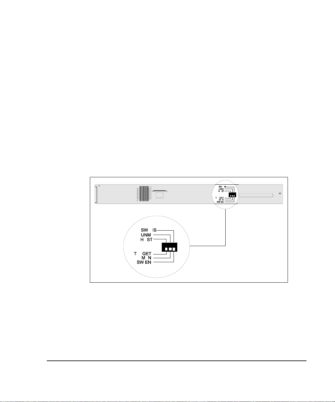
Host/Target DIP Switch
On the back panel of the 2724 hub is a HOST/TARGET DIP switch that
determines whether the hub is a host or target hub in a hub stack. For example,
you can connect up to two 2724 hubs and designate one as the host and the
other hub as a target for an unmanaged stack. Or, if you have a managing hub
(2824) in the stack, you can set up to four 2724 manageable hubs as target hubs
for a managed stack. The 2824 hub does not have a HOST/TARGET DIP
switch.
: There may be only one host hub in a stack. More than one host hub prevents
NOTE
the stack from passing Ethernet traffic or management commands between units.
1-9
Figure 1- 5.
2724 Hub DIP Switches
Compaq Netelligent 2724/2824 Dual-Speed Hub User Guide
Page 20

. . . . . . . . . . . . . . . . . . . . . . . . . . . . . .
Overview
1-10
Managed/Unmanaged DIP Switch
On the back panel of the 2724 hub is a MAN/UNM DIP switch that sets the
hub’s initial 100 Mb/s port enable/disable and backplane connection status.
When the switch is set to “MAN,” the hub sets the initial 100 Mb/s port
enable/disable and backplane connection status. When the switch is set to
“UNM,” the initial 100 Mb/s port and backplane status is set to the hardware
default (enabled). The 2824 hub does not have a MAN/UNM DIP switch.
: When a managing hub is present, it can set port statuses regardless of the
NOTE
switch setting.
Internal 10/100 Switch Disable DIP Switch
The internal 10/100 switch disable DIP switch, located on the back panel of the
2724 hub, lets you disable the internal two-port switch. When you set the switch
to “SW DIS,” the internal switch is disabled, preventing 10 Mb/s packets from
being forwarded to the 100 Mb/s segment and vice-versa. This effectively
isolates the 10 Mb/s segment and disables connectivity to the management
agent. When you set the switch to “SW EN,” the internal switch allows packets
to be forwarded between the 10 Mb/s and 100 Mb/s segments, unless the switch
is disabled by the management agent.
If you set the DIP switch to “SW EN,” you can enable and disable the switch
using the n2feTen100SwEnable MIB variable. However, if you set the DIP
switch to “SW DIS,” the hardware disables the bridge, which the management
agent cannot change.
You can view the status of the internal switch in the Netelligent 2000/FE (Fast
Ethernet) MIB variable n2feTen100SwHardwareDisableSwitchStatus.
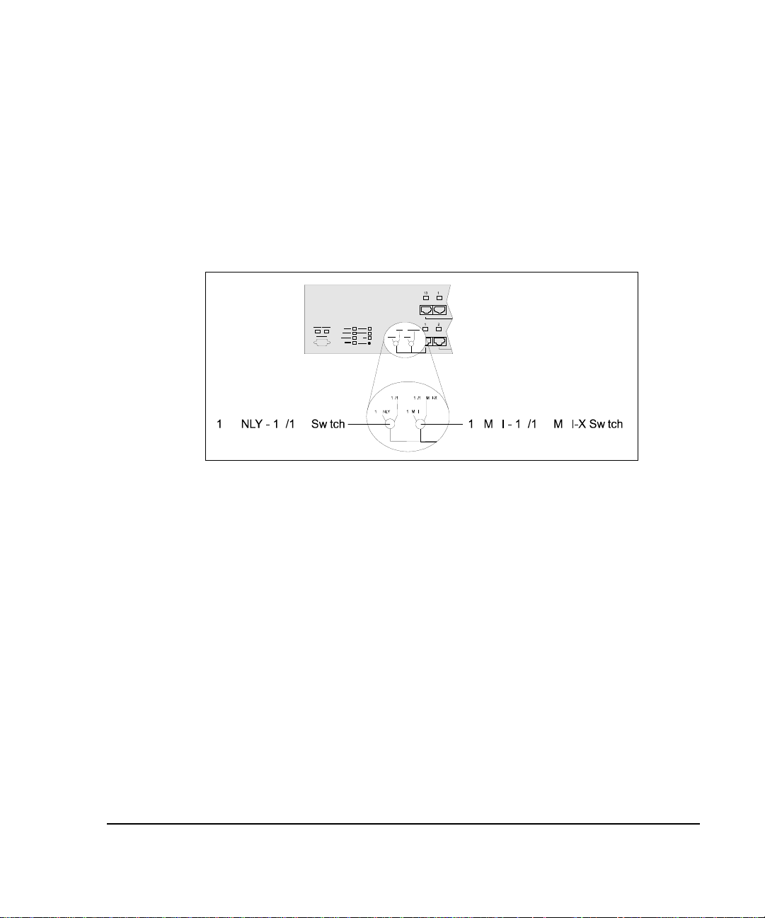
10 ONLY - 10/100 Switch
The 10 ONLY - 10/100 switch, located on the front panel of both 2724 and
2824 hubs, lets you set the allowable connection types for Port 1. When you set
the switch to “10 ONLY,” Port 1 allows 10 Mb/s connections only. When you
set the switch to “10/100,” Port 1 allows 10 Mb/s or 100 Mb/s connections.
Page 21
. . . . . . . . . . . . . . . . . . . . . . . . . . . . .
1-11
If the switch is set to “10/100,” you can force 10 Mb/s connections using the
n2fePortAutoNegCapAdvertised MIB variable. However, if the switch is set to
“10 ONLY,” the hardware forces the connection speed and cannot be changed
by the management agent. To view the status of this switch, see the
n2feForce10 Mb/sSwitchStatus MIB variable.
: This switch must be set to 10 ONLY if you set the 10 MDI / 10/100 MDI-X
NOTE
switch to 10 MDI.
Figure 1- 6.
Port 1 Switches
10 MDI - 10/100 MDI-X Switch
The 10 MDI / 10/100 MDI-X switch is located on the front panel of the 2724
and 2824 hubs. This switch lets you set Port 1 as an MDI 10Base-T (uplink)
port (for connecting to another hub) or as an MDI-X port (for connecting
directly to a network controller card). The 10 MDI setting is for 10Base-T
connections only.
: If you set this switch to 10 MDI, be sure the 10 ONLY - 10/100 switch is set
NOTE
to 10 ONLY.
Compaq Netelligent 2724/2824 Dual-Speed Hub User Guide
Page 22

. . . . . . . . . . . . . . . . . . . . . . . . . . . . . .
Overview
1-12
Segmentation
A segment is a single collision domain where all network traffic within that
domain contends for the same bandwidth. The Netelligent 2724/2824 hub has a
10 Mb/s segment and a 100 Mb/s segment that are connected via an internal
two-port (10 Mb/s / 100 Mb/s) switch. The process of segmentation lets you
isolate the 10 Mb/s segment from the 100 Mb/s segment, which prevents packet
forwarding between the two segments and isolates the hub’s 10 Mb/s segment
from the common 100 Mb/s backplane. This can improve the bandwidth in your
network by reducing the number of nodes that contend for the same segment
thereby reducing collisions. For information about isolating the
10 Mb/s segments, see “Internal 10/100 Switch Disable DIP Switch.”
You can also isolate the hub’s 100 Mb/s segment from the common 100 Mb/s
backplane in a stack. To do so, view the Stack Configuration screen of the
VT100 interface and set the Backplane Status field to “Isolated” (see “Appendix
B – Using the VT100 Interface” for more information). Or, set the
n2feBkplnStatus MIB variable using a MIB browser or SNMP management
application such as Compaq Netelligent Management Software.
All 2824/2724 ports have access to the management agent regardless of
connection speed as long as they have access to the stack’s common 100 Mb/s
backplane. When any hub’s internal 10/100 switch is disabled, its 10 Mb/s
connections lose their access to the agent. When a manageable hub (2724) is
isolated from the common 100 Mb/s backplane, all ports lose their access to the
management agent. 100 Mb/s connections on the managing (2824) hub always
have access to the agent, regardless of the hub’s configuration.
Page 23

. . . . . . . . . . . . . . . . . . . . . . . . . . . . .
2-1
Chapter 2
Planning Installation
This chapter contains installation requirements and system planning charts that
will help you prepare for installing the hub.
Installation Requirements
To help ensure a correct installation, read this section to determine the
environmental, electrical, spatial, and cable requirements.
Environmental Requirements
Be sure the operating environment for the hub is within the following ranges:
■
Temperature: 32° to 104° F (0° to 40° C)
■
Humidity: 5% to 95% (non-condensing)
■
Altitude: 0 to 10,000 feet (0 to 3 km)
■
Clearance: minimum of 2 inches (5.1 centimeters) on each side of the
hub (for proper ventilation)
Electrical Requirements
The electrical requirements for the hub are as follows:
■
Voltage: 100 to 240 VAC
■
Power: 2.0A (@ 100 VAC) to 1.0A (@ 240 VAC)
■
Frequency: 50 to 60 Hz
Compaq Netelligent 2724/2824 Dual-Speed Hub User Guide
Page 24

. . . . . . . . . . . . . . . . . . . . . . . . . . . . . .
Planning Installation
2-2
CAUTION:
grounded outlet. Do not use a three-to-two pronged adapter at the outlet.
Doing so may result in electrical shock and/or damage to the hub and will
void your warranty.
Spatial Requirements
The hub dimensions are 2.5 x 17 x 13.5 inches, 6.4 x 43.6 x 34.6 cm (HxWxD).
Be sure to allow at least 2 inches (5.1 centimeters) on each side of the hub for
proper air circulation and cable connections.
Cable Requirements
The following information states the required cable type and distance
limitations for 10Base-T, 100Base-TX, and 100Base-FX.
10Base-T
The 10Base-T twisted-pair wiring you connect to the hub’s RJ-45 ports must
meet the following minimum specifications and requirements to ensure longterm LAN reliability.
■
The wiring must be unshielded twisted-pair (UTP), Category 3 or better.
The power outlet must be a non-switched, three-pronged,
■
Two pairs of wiring are required.
■
The building codes may require different insulation materials.
■
The wire gauge should be between 18 and 26 AWG. (Most telephone
installations use 24-gauge wiring.)
■
UTP wire should meet the following requirements:
Solid copper
Nominal capacitance: less than 16 pF/ft
Nominal impedance: 100 Ohms
Nominal attenuation: less than 11.5 db
Page 25

. . . . . . . . . . . . . . . . . . . . . . . . . . . . .
2-3
100Base-TX
100Base-TX is the IEEE 802.3u specification for transmitting 100 Mb/s
Fast Ethernet over two pairs of copper wire. The pinout, connectors (RJ-45
modular plugs), and protocol (CSMA/CD) are exactly the same as
for 10Base-T.
Unshielded Twisted Pair (UTP)
■
Category 5 only
■
Two pairs used (same as 10Base-T)
■
Maximum 100-meter (328-foot) link
Figure 2-1 shows a one-to-one cable pinout for 100Base-TX.
Figure 2- 1.
NOTE:
One-to-One Cable Pinout for 100Base-TX
To prevent potential electromagnetic interference, terminate the unused
wires (4, 5, 7, and 8).
Tables 2-1 and 2-2 show the wiring for straight-through and crossover twistedpair cable.
Table 2- 1
Straight-Through Twisted-Pair Wiring
Twisted Pair Number Pin Number Signal
Description
11
2
23
6
TD+
TD-
RD+
RD-
Compaq Netelligent 2724/2824 Dual-Speed Hub User Guide
To Pin Number Signal
Description
➔
➔
➔
➔
1
2
3
6
TD+
TD-
RD+
RD-
Page 26

. . . . . . . . . . . . . . . . . . . . . . . . . . . . . .
Planning Installation
2-4
Table 2-2
Crossover Twisted-Pair Wiring
Twisted Pair Number Pin Number Signal
Description
11
2
23
6
TD+
TD-
RD+
RD-
To Pin Number Signal
Description
➔
➔
➔
➔
3
6
1
2
RD+
RD-
TD+
TD-
100Base-FX
100Base-FX is the IEEE 802.3u specification for transmitting 100 Mb/s Fast
Ethernet over two strands (one pair) of fiber optic cable. The 2724/2824 hub
supports both SC type (low-cost fiber optic interface connector) and ST (optical
medium connector plug and socket) connections.
Cable Type
■
Fiber optic
■
Multi-mode 62.5/125 to 100/150 micron fiber
■
Both strands used
Page 27
. . . . . . . . . . . . . . . . . . . . . . . . . . . . .
2-5
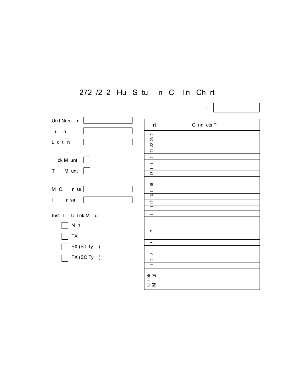
System Planning Charts
The charts in Figures 2-2 and 2-3 provide a convenient way of planning the
connections for your hub.
Figure 2- 2.
Hub Setup and Cabling Chart
Compaq Netelligent 2724/2824 Dual-Speed Hub User Guide
Page 28
. . . . . . . . . . . . . . . . . . . . . . . . . . . . . .
Planning Installation
2-6
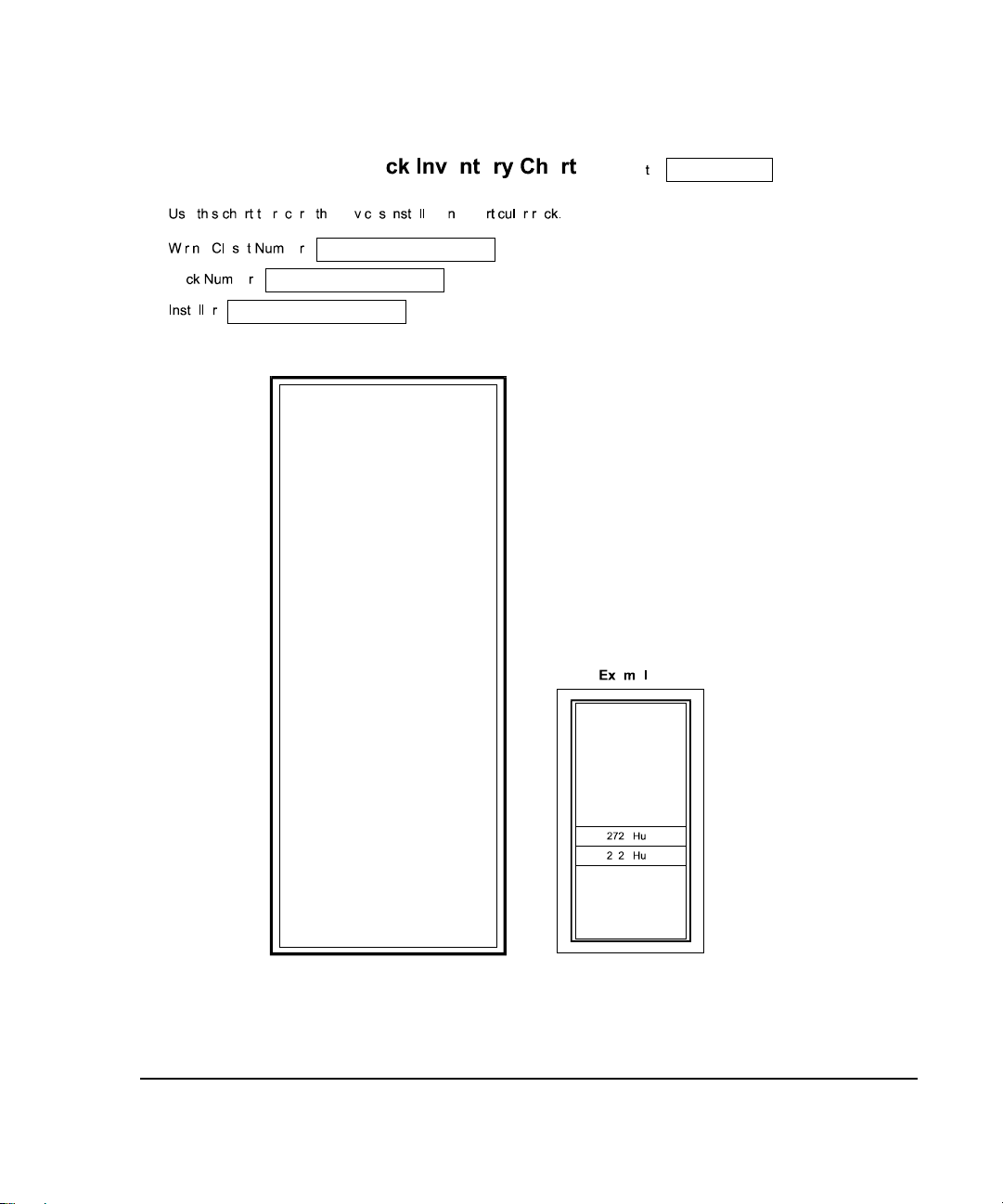
Figure 2- 3
. Rack Inventory Chart
Page 29

. . . . . . . . . . . . . . . . . . . . . . . . . . . . .
3-1
Chapter 3
Installing the Hub
This chapter explains how to mount the hub, attach cables, and connect power.
Mounting the Hub
You can place the hub on a level surface (table top or shelf, for example) or
mount it in a standard EIA 19-inch rack.
Attaching the Rubber Feet
If you will place the hub on a table top or shelf, attach the supplied adhesivebacked rubber feet, as described in the following steps.
1. Turn the hub over so that its bottom side faces up.
2. Remove the four rubber feet from their packaging.
3. Peel the protective paper backing off the rubber feet. Then position the
feet in the recessed areas near the corners of the hub and press the feet
into place.
4. Turn the hub to its upright position and place it on the
mounting surface.
: Be sure you allow at least 2 inches (5 cm) on each side of the hub for proper
NOTE
air flow.
Rack-Mounting the Hub
The hub occupies 1 ½ slots in a standard 19-inch rack. To mount the hub in a
rack, use the supplied installation kit. This kit includes two side mounting
brackets, eight bracket screws, and four larger rack-mount screws.
Compaq Netelligent 2724/2824 Dual-Speed Hub User Guide
Page 30
. . . . . . . . . . . . . . . . . . . . . . . . . . . . . .
Installing the Hub
3-2
To attach the brackets, follow these steps:
1. Remove the two screws from the left and right side of the hub. (These
screws are extras and are not needed to install the
mounting brackets.)
2. Position the bracket as shown in Figure 3-1 and secure it with the
smaller bracket screws. Then attach the remaining bracket to the other
side of the hub.
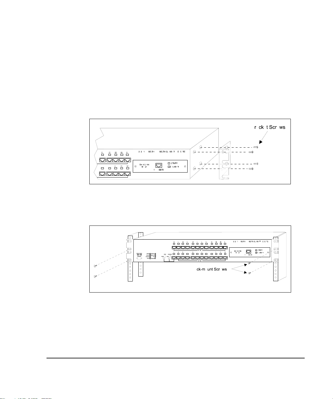
Figure 3- 1.
3. After you attach both mounting brackets, position the bracket slots over
Figure 3- 2.
Attaching the Mounting Brackets
the desired holes on the rack (Figure 3-2). Then insert and tighten the
supplied rack-mount screws.
Positioning the Hub in a Rack
Page 31

. . . . . . . . . . . . . . . . . . . . . . . . . . . . .
3-3
Installing a Smart Uplink Module
The Netelligent 2724/2824 hubs have a Smart Uplink slot that lets you install
one of the following optional Smart Uplink modules (SUMs):
■
100Base-TX version (Part No. 267045-001)
➀
■
100Base-FX (fiber) version with ST connector
➁
(Part No. 267042-001)
■
100Base-FX (fiber) version SC connector (Part No. 267043-001)
➂
c
d
e
Figure 3- 3.
NOTE:
Inserting the Smart Uplink Module into the
Smart Uplink Slot
To insert a Smart Uplink Module into a Netelligent 2724 or 2824 Smart Uplink
slot, follow these steps:
1. Power down the hub by disconnecting the power cord from the power
Smart Uplink Modules
The Smart Uplink Module port is the 25th logical port on the hub.
source.
Compaq Netelligent 2724/2824 Dual-Speed Hub User Guide
Page 32

. . . . . . . . . . . . . . . . . . . . . . . . . . . . . .
Installing the Hub
3-4
2. Remove the Smart Uplink port cover plate from the hub’s front panel.
3. Insert the Smart Uplink module through the port hole, aligning the sides
of the SUM with the card guides inside the hub (Figure 3-4).
Figure 3- 4.
4. Carefully push the Smart Uplink module's 50-pin male connector into the
5. Secure the SUM to the hub by tightening the SUM's spring screws.
SUM Installation
SUM socket on the hub motherboard until the SUM is firmly seated and
its faceplate is flush with the hub's front panel.
CAUTION:
completing Step 4 of this procedure. If you tighten the spring screws before
the SUM is properly seated in the socket, you may damage the hub.
Do not tighten the Smart Uplink Modules spring screws until
Page 33

. . . . . . . . . . . . . . . . . . . . . . . . . . . . .
3-5
Connecting Cable
Each RJ-45 port on the hub can accept a standard 8-wire twisted-pair (UTP)
cable that ends with RJ-45 connectors. This type of cable can be up to 100
meters (328 feet) in length.
A 100Base-FX port on a SUM can accept multi-mode 62.5/125 to 100/150
micron fiber cable that ends with fiber SC-type connectors. This type of cable
can be up to 2 Km in length at full-duplex operation.
To attach the cable, plug one of the cable connectors into the selected port on
the hub. Connect the other end of the cable to the corresponding port on a
10Base-T, 100Base-TX, or 100Base-FX workstation (if you installed a
100Base-FX SUM).
Figure 3- 5.
Connecting Twisted-Pair Cable to an RJ-45 Port
Compaq Netelligent 2724/2824 Dual-Speed Hub User Guide
Page 34

. . . . . . . . . . . . . . . . . . . . . . . . . . . . . .
Installing the Hub
3-6
Interconnecting Hubs
You can interconnect two manageable 2724 hubs to create an unmanaged stack.
Or, you can interconnect up to four manageable 2724 hubs with one managing
2824 hub for a fully managed stack. You can also interconnect the 2724 and
2824 hubs with Netelligent 2524 (manageable) and 2624 (managing) hubs.
: Only one managed hub (2824 or 2624) is allowed in a single stack.
NOTE
CAUTION:
before you add another hub to the stack. Adding a hub with the stack
powered on could create unpredictable results.
You can place the 2824 hub in any position (top, middle, bottom) in a two- to
five-hub stack. The 2824 hub has an expansion interface that consists of four
68-pin backplane connection cables (EXPN PORT A, B, C, and D) on the hub's
back panel.
The 2724 hub has one 68-pin backplane connection cable (EXPN PORT) and
three dip switches for UNM/MAN, HOST/TARGET, and SW EN/SW DIS
settings. The switch settings are described in the section “2724 Dip Switch
Settings” in this chapter.
If possible, mount the hubs on a rack or place them on a stable mounting
surface with the supplied rubber feet affixed before you attach the backplane
connection cable. This helps ensure the correct spacing between hubs and helps
prevent stretching and possibly damaging the backplane connection cable
during installation.
It is recommended that you power down the 2724/2824 stack
2724 Dip Switch Settings
The dip switches on the back of the 2724 hub come factory pre-set so that you
can create a managed stack of up to five hubs (one to four 2724 hubs and one
2824 hub). Or, by reconfiguring the dip switches, you can create an unmanaged
stack of two 2724 hubs. The dip switch settings are described below:
IMPORTANT:
may affect switch management.
Incorrectly setting the dip switches will
damage the hubs, but
not
Page 35

. . . . . . . . . . . . . . . . . . . . . . . . . . . . .
3-7
HOST/TARGET
■
TARGET (Factory default setting) Lets you connect one, two, three,
or four 2724 hubs to a 2824 managing hub to form a “managed” dualspeed hub.
■
HOST Lets you connect two 2724 hubs in an unmanaged stack to
form a single 48-port dual-speed hub (with no 2824 hub in the stack).
One hub must be re-configured as the HOST and the other as the
TARGET.
Invalid Connections
The following are invalid connections for the 2724/2824 hubs:
■
Connecting two 2824 managing hubs together Hubs will operate as if
disconnected.
■
Setting a 2724 hub in a managed stack to the HOST mode Hubs will
operate as if disconnected. The STATUS LED is always off in an
unmanaged stack. To correct this condition, set the DIP switch on the
2724 hub to TARGET.
■
Setting both 2724 hubs in an unmanaged stack to HOST or to the
TARGET mode The STATUS LED is always off in an unmanaged
stack. To correct this condition, set the DIP switch on one hub to HOST
and set the DIP switch on the other hub to TARGET.
UNM/MAN
■
UNM (Unmanaged) In this mode, if you change the DIP switch on
the 2724 hub to UNM, all hub ports on the 2724 are automatically
enabled after turning the hub off and then back on. This mode lets you
use a 2724 under the following conditions:
❏
The 2724 is disconnected from the 2824.
❏
The 2824 is off or otherwise not operating.
Compaq Netelligent 2724/2824 Dual-Speed Hub User Guide
Page 36

. . . . . . . . . . . . . . . . . . . . . . . . . . . . . .
Installing the Hub
3-8
■
MAN (Managed) (Factory-default setting) In this mode, the port
configuration settings for the 2724 hub are non-volatile. In addition, if
you remove the 2724 hub from the stack, the disabled ports remain
disabled. (You can re-enable them by setting the DIP switch to UNM
and turning the hub off and then back on.) For example, if you disable
Ports 1 and 2, then power down the stack, Ports 1 and 2 will still be
disabled when the stack is powered up again.
In a managed stack, if you set the 2724 DIP switch to UNM, the
STATUS LED on the 2724 flashes GREEN.
Figure 3-6 shows two expansion ports of a 2824 hub connected to the expansion
ports of two 2724 hubs using backplane connection cables.
Figure 3- 6.
In this example, the 2824 hub (top hub in the stack) manages two 2724 hubs.
The DIP switches on both 2724 hubs are set to “TARGET,” as required in a
managed stack.
Stack Connecting One 2824 and Two 2724 Hubs with Backplane Connectors
Page 37

. . . . . . . . . . . . . . . . . . . . . . . . . . . . .
3-9
Figure 3-7 shows two 2724 hubs connected via a backplane connector between
the EXPN PORTs. The DIP switches on the 2724 hubs are set with the top hub
as the HOST and the bottom hub as the TARGET.
Figure 3- 7.
In this example, the unmanaged stack consists of the maximum of two 2724
hubs. Either hub in the stack can be the HOST or the TARGET. Both hubs are
in the factory-default MAN mode.
Interconnecting Two 2724 Hubs Via a Backplane Connection Cable
Compaq Netelligent 2724/2824 Dual-Speed Hub User Guide
Page 38

. . . . . . . . . . . . . . . . . . . . . . . . . . . . . .
Installing the Hub
3-10
Connecting Power
Follow these steps to connect the hub to power:
1. Plug the power cord into the power connector on the back of the hub.
2. Insert the three-pronged plug on the power cord into a non-switched
grounded power source. The power source should be near the hub and
easily accessible.
Figure 3- 8.
When you plug in the power cord, the hub performs a self test in which the
RJ-45 LEDs are green (or yellow if collisions are occurring), off, yellow, and
off again. Each state is about ½ second in duration. After the test, the POWER
LED lights steady green.
Connecting the Power Cord
Page 39

. . . . . . . . . . . . . . . . . . . . . . . . . . . . .
3-11
Disconnecting Power
To power down the hub, disconnect the power cord from the power source. Do
not power down the hub by disconnecting the power cord from the back of the
hub.
Connecting to the Serial Port
To enable management of the hub, you must first set its IP address (See Chapter
4 – “Setting the IP Address”). One way to set the IP address is through the hub's
built-in VT100 interface. To use this interface, you must connect a workstation
to the hub’s serial port using a null modem (to set the IP address locally) or to a
regular modem (to set the IP address remotely). The serial cable has a DB-9
connector at each end. Figure 3-9 shows a connection to a workstation using a
null modem. Figure 3-10 shows an Example of a connection to a workstation
via a regular modem.
Compaq Netelligent 2724/2824 Dual-Speed Hub User Guide
Page 40

. . . . . . . . . . . . . . . . . . . . . . . . . . . . . .
Installing the Hub
3-12
Figure 3- 9.
Local Connection via Null Modem
Page 41

. . . . . . . . . . . . . . . . . . . . . . . . . . . . .
3-13
Figure 3- 10.
Remote Connection via Regular Modem
Compaq Netelligent 2724/2824 Dual-Speed Hub User Guide
Page 42

. . . . . . . . . . . . . . . . . . . . . . . . . . . . .
4-1
Chapter 4
Configuring the Hub for
Management
To allow management of the 2824 hub, you must first set its IP address. After
you set the IP address, you can set additional configuration parameters using the
VT100 interface discussed in Appendix A “Using the VT100 Interface.” Or,
you can manage the hub using Compaq Netelligent Management Software,
which is included on CD with the hub.
Setting the IP Address Using VT100
The following procedure describes how to initially set the IP address using
Windows 95 HyperTerminal. However, the settings described in these steps
apply to any terminal emulation application. After you set the IP address the
first time, you can change the address using the VT100 interface, Netelligent
Management Software, or other SNMP management application. Follow these
steps to set the IP address using VT100.
: You can also set the IP address using a BOOTP server. See Setting the IP
NOTE
Address Using a BOOTP Server at the end of this chapter.
1. Connect the modem as described in “Connecting a Modem” in
Chapter 3 “Installing the Hub.”
2. Start the terminal emulation program.
Netelligent 2724/2824 10/100Base-T Hub User Guide
Page 43

. . . . . . . . . . . . . . . . . . . . . . . . . . . . .
Configuring the Hub for Management
4-2
3. Type a name for the connection (for example, “IP Setup”) and click
on OK.
Figure 4- 1.
4. Select the Direct to Com 1 option (in this example) in the Connect using
field of the Phone Number dialog box. Click on OK.
Connection Description Screen
Page 44

. . . . . . . . . . . . . . . . . . . . . . . . . . . . .
4-3
Figure 4- 2.
Phone Number Dialog Box
5. Enter the following port settings in the dialog box and click on OK.
❏
Bits per second: 9600
❏
Data bits: 8
❏
Parity: None
❏
Stop bits: 1
❏
Flow control: None
Netelligent 2724/2824 10/100Base-T Hub User Guide
Page 45

. . . . . . . . . . . . . . . . . . . . . . . . . . . . .
Configuring the Hub for Management
4-4
Figure 4- 3.
6. Enter the following command:
The Login screen appears.
NOTE:
COM1 Properties Dialog Box
vt100
If the login fails, you may need to retry the connection several times.
Page 46

. . . . . . . . . . . . . . . . . . . . . . . . . . . . .
4-5
Figure 4- 4.
7. Within 20 seconds after the Login screen appears, type and enter the
word “public,” which is the default password. The Main menu screen
appears.
Figure 4- 5.
Login Screen
Main Menu Screen
Netelligent 2724/2824 10/100Base-T Hub User Guide
Page 47

. . . . . . . . . . . . . . . . . . . . . . . . . . . . .
Configuring the Hub for Management
4-6
8. Highlight Option B, Management Agent Configuration, using the down
arrow key or <Tab> key. Then press <Enter>. The Management Agent
Configuration screen appears.
Figure 4- 6.
9. Use the arrow or tab keys to move to the IP Address field. Then enter the
IP address for the Ethernet interface. To set the IP address for other
interfaces (for example, SLIP), use the “<” and “>” keys to scroll to
group and repeat this step.
10. Move the cursor to the Accept Changes field and press <Enter>. Then
move the cursor to the Return to menu field and press <Enter>.
11. Select Option J (Logout) to log out of the VT100 session.
You can change the initialization string using the Modem Setup screen of the
VT100 interface. For example, you could set the string as “Enter VT100 now”
to provide a more instructive cue to enter the VT100 command. You can also
change the password to log in to VT100 using the Change Password screen. For
a complete description of the VT100 interface, see Appendix B “Using the
VT100 Interface.”
Management Agent Configuration Screen
Page 48

. . . . . . . . . . . . . . . . . . . . . . . . . . . . .
4-7
Setting the IP Address
Using a BOOTP Server
You can configure a BOOTP server to supply the IP address, subnet mask, and
gateway IP address for the hub. Once the BOOTP server is configured with the
desired settings, it automatically configures the hub in response to the hub’s
BOOTP requests.
The 2824 hub has two boot phases: Boot and Runtime. In the Boot phase
(STATUS LED is orange), the hub issues as many requests as are defined in the
cpqnBootpRetries MIB object The default number of requests is two. The hub
issues the requests using two different frame types (Ethernet_II and 802.2
SNAP). The interval between requests is defined in the cpqnBootpRetryInterval
MIB object. The default request retry interval is 5 seconds. In the Runtime
phase (STATUS LED is green) and when BOOTP requests are enabled and the
hub does not have an IP address currently assigned, the hub issues requests
every 5 minutes using only one frame type (same as the IP frame type). If the
hub receives a response from the server, it uses the information to configure
itself accordingly.
You can use Compaq Netelligent Management Software (or other SNMP
network management application) or the hub’s VT100 interface to disable
BOOTP requests by setting the cpqnBootEnable MIB object to
disable-bootp(1). This is recommended if you use only IPX communication, as
it helps reduce unnecessary traffic generated by the hub.
Netelligent 2724/2824 10/100Base-T Hub User Guide
Page 49

. . . . . . . . . . . . . . . . . . . . . . . . . . . . .
5-1
Chapter 5
Managing the Hub
This chapter discusses the management functions of the Netelligent 2824 hub.
Management Features
The 2824 hub has the following management features:
■
Support for SNMP, VT100, and Compaq Netelligent Management
Software management applications
■
Four-group Remote Monitoring (RMON)
■
Firmware upgrade capabilities
Management Interface
After you set the IP address for the 2824 hub (described in Chapter 4,
“Configuring the Hub for Management”), you can use BOOTP, VT100, SNMP,
or Compaq Netelligent Management Software to configure the network
parameters and manage the hub. Each of these methods varies in the
management functions it can perform. The following table lists network
configuration parameters and the various management interfaces you can use to
modify them.
Compaq Netelligent 2724/2824 Dual-Speed Hub User Guide
Page 50

. . . . . . . . . . . . . . . . . . . . . . . . . . . . .
Managing the Hub
5-2
Network Configuration Parameters and Modification Methods
Network Configuration
Parameters
IP address
IP network mask
IP gateway
SLIP IP address
SLIP IP network mask
SLIP IP gateway
IPX address IPX network of requester + MAC address
BOOTP request enable
BOOTP retries
BOOTP retry interval
IP frame type
IPX frame type
IP autodiscovery enable
Modification Methods Default Parameter Setting
BOOTP VT100 SNMP
99 99 99
99 99 99
99 99 99
99 99
99 99
99 99
99 99
99 99
99 99
99 99
99 99
99 99
0.0.0.0
Derived from IP address
0.0.0.0
0.0.0.0
Derived from SLIP address
0.0.0.0
Enabled
2
5 seconds
Ethernet II
Ethernet 802.2
Enabled
IP autodiscovery ping interval
SAP broadcast
IP trap receivers
IPX trap receivers
Table 5-1
. Network Configuration Parameters and Modification Methods
99 99
99 99
99
99
55 seconds
Enabled
None
None
Page 51

. . . . . . . . . . . . . . . . . . . . . . . . . . . . .
5-3
SNMP Management
The 2824 hub supports SNMP management through both in-band and out-ofband communications. In-band management support is provided by SNMP over
IP and IPX protocol stacks and VT100 emulation over Telnet (TCP/IP). Out-ofband management support is provided by SNMP over SLIP and through direct
serial interfaces using VT100 emulation. The 2824 hub stores management
configuration information in Non-Volatile RAM (NVRAM), which helps
protect the configuration from a power outage. See “Parameters Stored in
NVRAM.”
Supported MIBs
The 2824 hub supports the following standard MIBs under SNMP, which
determine what management functions it can perform:
■
RFC1213 (MIB II) Management Information Base for Network
Management of TCP/IP-based Internets (MIB II)
■
RFC1516 Definitions of Managed Objects for the IEEE 802.3
Repeater Devices (technically part of MIB II)
■
RFC1757 (RMON) Remote Network Monitoring Management
Information Base (RMON MIB)
■
HUBNVLE Novell Ethernet Repeater MIB
■
CPQN2FE Compaq Netelligent 2000 Fast Ethernet MIB
■
CPQNUNIF Compaq Netelligent Unified MIB
Supported Frame Types
The hub supports four different Ethernet frame types. It is important to know
that the 2824 hub supports the frame types used in your network. For
convenience, each frame type is referred to by its Novell name. The following
table lists each frame type, its Novell name, and whether or not it is supported
for IP and IPX.
Compaq Netelligent 2724/2824 Dual-Speed Hub User Guide
Page 52

. . . . . . . . . . . . . . . . . . . . . . . . . . . . .
Managing the Hub
5-4
Supported Frame Types
Ethernet Frame Type Novell Name IP IPX
DIX Ethernet II ETHERNET_II
99 99
IEEE 802.3 with 802.2 SNAP Headers ETHERNET_SNAP
IEEE 802.3 with 802.2 LLC Headers ETHERNET_802.2
IEEE 802.3 Raw ETHERNET_802.3
IP Frame Types
The hub supports both ETHERNET_II and ETHERNET_SNAP for its Ethernet
IP communications. The default frame type is ETHERNET_II. However, many
networks composed of FDDI, token ring, and Ethernet topologies require the
ETHERNET_SNAP frame type for routing, bridging, and switching. To
provide IP management flexibility, the 2824 hub supports both ETHERNET_II
and ETHERNET_SNAP frame types.
Although the hub supports two different Ethernet frame types, it cannot support
both simultaneously. This is because an individual IP network can only use one
frame type and different frame types require different IP networks even if they
run on the same cable.
99 99
99
99
Page 53

. . . . . . . . . . . . . . . . . . . . . . . . . . . . .
5-5
The hub’s IP frame type can be set by three different methods:
■
BOOTP Sends requests over ETHERNET_II and/or
ETHERNET_SNAP frame types, which you can configure, as needed.
The hub’s IP frame type is set to the frame type of the BOOTP response
(if it is received) and saved in non-volatile memory.
If the hub transmits BOOTP requests over two frame types, this
NOTE:
lengthens the time required to complete the BOOTP process.
■
SNMP If you set the frame type using SNMP over IP, you must set
the IP address using the cpqnIpAddr MIB variable. SNMP over IPX
does not require an IP address configuration.
■
VT100 You can set the hub’s IP frame type from the Management
Agent Configuration screen. The 2824 hub saves changes in non-volatile
memory.
If you are using Telnet or SNMP over IP, the hub must already have a
NOTE:
valid configuration for either its IP or SLIP interface.
To determine which IP frame type it will implement, the hub uses the following
priority scheme:
■
If a BOOTP response is received during the BOOTP process, uses the
frame type of the received packet
■
If no BOOTP response is received during the BOOTP process, uses the
frame type saved in non-volatile memory
■
If no value is stored in non-volatile memory, uses the default value of
ETHERNET_II
At any time after the initial BOOTP process, you can change the frame type
using VT100 or by setting the MIB object cpqnIpFrameType.
Compaq Netelligent 2724/2824 Dual-Speed Hub User Guide
Page 54

. . . . . . . . . . . . . . . . . . . . . . . . . . . . .
Managing the Hub
5-6
IP Protocols
The hub supports the following IP protocols:
UDP (User Datagram Protocol)
ARP (Address Resolution Protocol)
ICMP (Internet Control Messages Protocol)
SNMP (Simple Network Management
Protocol)
BOOTP (Boot Protocol)
TFTP (Trivial File Transfer Protocol)
TCP (Transmission Control Protocol)
Telnet
Provides non-guaranteed delivery service over IP. The hub
implements a full UDP stack. Supports IP fragmentation maximum
packet size of 1520 bytes.
Allows discovery of the hardware address associated with a given
IP address
Provides error and control messages. A Ping packet is a type of
ICMP packet.
Allows management of a network node by another node. The hub
provides full support of SNMP and implements several standard
MIBs as well as product-specific MIBs.
Allows a network node to automatically obtain its IP configuration
from a central BOOTP server; an alternative to individually
configuring each node. Also used to trigger a TFTP firmware
download.
Supported for firmware upgrades
Provides guaranteed delivery service over IP. It is required for Telnet
support.
Provides terminal emulation over a network. This is the VT100
interface.
IP Autodiscovery
The hub supports a generic IP autodiscovery method used by many of the
leading SNMP management platforms (such as HP OpenView, SunNet
Manager, IBM NetView 6000). This method lets the management platforms
automatically discover managing 2824 hub in the network.
Page 55

. . . . . . . . . . . . . . . . . . . . . . . . . . . . .
5-7
Generic IP autodiscovery works by looking at the addresses cached by routers
and gateways. These caches are periodically flushed. For a node to remain in
the gateway’s cache, it must transmit at least as often as the cache is flushed.
The 2824 hub implements IP autodiscovery via two MIB objects, each of which
is stored in non-volatile memory.
MIBs Implementing IP Autodiscovery
MIB Object Function
cpqnIpPingPktRate
cpqnIpAutoDiscoveryStatus
IPX Frame Type
In addition to IP, the 2824 hub also supports an IPX protocol stack. To provide
seamless network management, all Ethernet frames types supported by Novell
must be supported by hubs. The firmware supports the following frame types
for IPX:
■
■
■
■
ETHERNET_II
ETHERNET_802.3
ETHERNET_802.2
ETHERNET_SNAP
Sets the rate of ping transmissions so that it can match
the IP gateways cache aging timer, preventing the 2824
hub hub from being deleted from the ARP cache. If you do
not configure a default IP gateway (set through either
SNMP or VT100 management interfaces), the hub does
not transmit the periodic ICMP Pings and cannot
guarantee IP autodiscovery. Default 55 seconds.
Disables or enables IP autodiscovery.
Default =
discover
(1)
Compaq Netelligent 2724/2824 Dual-Speed Hub User Guide
Page 56

. . . . . . . . . . . . . . . . . . . . . . . . . . . . .
Managing the Hub
5-8
IMPORTANT:
IPX, the default IPX frame type of the hub is also ETHERNET_802.2.
Most IPX communications uses IPX packets that are initiated by a requestor,
not the hub. A management station sends these packets to the hub and waits for
a response. The hub receives the packet and sends it back using the same frame
type and IPX network number used to send the packet. For response traffic,
therefore, the hub supports all IPX frame types.
In addition, the hub originates some types of IPX traffic, such as packets for
SNMP traps and RIP and SAP broadcasts. Consequently, to transmit the packet,
the hub must know the IPX frame type and network number. This requires the
use of MIB variables, one of which is the IPX frame type variable.
To determine which IPX frame type it will implement, the hub uses the
following priority scheme:
■
Uses the value stored in NVRAM
■
If no value is stored in NVRAM, uses the default value of
ETHERNET_802.2
You can change the frame type at any time by setting the IPX frame type MIB
variable through the VT100 interface, SNMP, or Compaq Netelligent
Management Software.
Since Novell uses ETHERNET_802.2 as the default frame type for
The IPX network numbers for SNMP traps are determined through the MIB
variables indicating the IPX trap receiver addresses. IPX network numbers for
RIP and SAP broadcasts are learned by analyzing the RIP broadcasts sent from
IPX routers on the network. If the network number cannot be learned through
the network traffic, the default network number 0 is used.
Page 57

. . . . . . . . . . . . . . . . . . . . . . . . . . . . .
5-9
IPX Protocols
The hub supports the following IPX protocols:
IPX Protocol Function
SNMP
(Simple Network Management
Protocol)
Functions the same as SNMP over IP. All SNMP features available over IP
are available over IPX. Novells ManageWise uses SNMP over IPX to
manage HMI hubs, which the hub emulates.
IPX Diagnostics
SAP (Service Advertising Protocol)
RIP (Routing Information Protocol)
Allows a node to report which IPX functions it supports. The hub supports
IPX Diagnostics to be compatible with Novells NetExplorer server, a part of
ManageWise.
Allows a node to advertise which IPX services it supports. The hub
advertises two services:
•
HMI services (SAP ID 0x0239) Causes ManageWise to recognize
the hub as a manageable repeater
•
Netelligent services (SAP ID 0xAF05) Can be used to select an
icon for display on the ManageWise segment map
NetWare servers store the available service in the Bindery from which
other servers and management applications, such as ManageWise, can
query it.
Allows IPX nodes to exchange routing information. The hub uses RIPs to
determine the IPX number(s) and Ethernet frame type(s) of its local
segment; determines how to route SNMP/IPX traps; and supports IPX
autodiscovery.
Compaq Netelligent 2724/2824 Dual-Speed Hub User Guide
Page 58

. . . . . . . . . . . . . . . . . . . . . . . . . . . . .
Managing the Hub
5-10
IPX Autodiscovery
The hub supports Novell IPX autodiscovery through its HMI-compliance
mechanism so that management platforms, such as Novell’s ManageWise, can
automatically discover managing hub. The protocols involved in IPX
autodiscovery support are SAP, RIP, and IPX Diagnostics.
Using SAP, the hub advertises that it is an HMI server (although not all of the
server functions are implemented). This registers the hub in the Binderies of all
the NetWare servers on the network segment. When Novell's NMS or
ManageWise initiates autodiscovery, it queries the Binderies of all the servers it
knows to obtain the internal IPX address of HMI servers. ManageWise then
uses RIP to obtain the hub’s MAC address and other information required to
start SNMP/IPX management.
IPX Diagnostics are implemented only to support the NetExplorer server. This
protocol is not directly involved with the IPX autodiscovery algorithm, but is
used to update the ManageWise database with the current network
configuration.
NetWare servers age out Bindery entries after 60 seconds. To remain in a
server’s Bindery and stay available for autodiscovery by ManageWise, the hub
broadcasts SAPs every 55 seconds. You can disable this feature by setting the
MIB object cpqnIpxSAPBcastStatus to no-ipx-SAPs(2). The value of this object
is stored in non-volatile memory.
SLIP Protocols
The 2824 hub uses SLIP (Serial Line IP) to provide remote, out-of-band
management through the serial port. The same IP protocols supported over
Ethernet are also supported over SLIP, including SNMP and Telnet.
IP fragmentation is supported over SLIP. Fragmentation allows the hub to
receive the same maximum IP packet size, 1520 bytes, for both SLIP and
Ethernet. The maximum packet size over SLIP is 1006 bytes.
To establish a SLIP connection, you must set the IP address and the subnet
mask for the SLIP interface, using the VT100 interface or SNMP management.
Page 59

. . . . . . . . . . . . . . . . . . . . . . . . . . . . .
5-11
Traps
To receive a trap, the SNMP network management station must place its IP or
IPX address into the appropriate trap destination table of the Netelligent Unified
MIB (CPQNUNIF). The trap destination tables are listed below:
■
For IP traps, the destination table is cpqnIpTrapDestTable
■
For IPX traps, the destination table is cpqnIpxTrapDestTable
Each IP and IPX trap tables can contain a maximum of ten entries.
The table below summarizes the traps generated by the hub. The headings are
defined as follows: MIB is the MIB or RFC that defines the traps. Trap lists the
traps by a convenient name. RFC1157 Trap Type lists the RFC1157 generic trap
category to which the trap belongs; for enterpriseSpecific traps, the enterprise
and trap numbers are also shown. Variable Bindings lists the additional MIB
objects included in the trap message.
Generated Traps
MIB Trap RFC1157 Trap Type Variable Bindings
RFC1157 Cold Start
Authentication
Failure
RFC1757
(RMON)
RFC1516** Health
Rising Alarm
Falling Alarm
Group Change
Reset
coldStart
authenticationFailure
enterpriseSpecific
enterpriseSpecific
enterpriseSpecific
snmpDot3RptrMgt
enterpriseSpecific
snmpDot3RptrMgt
enterpriseSpecific
snmpDot3RptrMgt
(1) (none)
(6):
(6):
(6):
(6):
(6):
(4) (none)
rmon
.1
rmon
.2
.1
.2
.3
alarmIndex, alarmVariable, alarmSampleType,
alarmValue, alarmRisingThreshold
alarmIndex, alarmVariable, alarmSampleType,
alarmValue, alarmFallingThreshold
rptrOperStatus, rptrHealthText
rptrGroupIndex
rptrOperStatus
Compaq Netelligent 2724/2824 Dual-Speed Hub User Guide
Page 60

. . . . . . . . . . . . . . . . . . . . . . . . . . . . .
Managing the Hub
5-12
HUBNVLE**Health enterpriseSpecific(6):
nSnmpDot3RptrMgt
Group Change
Reset
** RFC1516 traps and HUBNVLE traps are issued under the same circumstances. Because of this, the hub issues traps
from one or the other MIB, but not both. The CPQN2FE MIB variable
issued.
enterpriseSpecific
nSnmpDot3RptrMgt
enterpriseSpecific
nSnmpDot3RptrMgt
.1
(6):
.2
(6):
.3
rptrBasHealthState, rptrBasHealthText,
rptrBasHealthData, rptrBasID, rptrExtName
rptrBasGroupMap, rptrBasId, rptrExtName
rptrBasHealthState, rptrBasHealthText,
rptrBasHealthData, rptrBasID, rptrExtName
n2feTrapSupport
lets you select which traps are
The following table describes when the 2824 hub issues each trap. The Health,
Group Change, and Reset traps are listed only once since they are issued under
the same circumstances.
Traps Issued
Trap Issued When
Cold Start
Authentication Failure
Rising Alarm
Falling Alarm
Health
Group Change
Reset
Issued when the hub has completed a re-initialization
Issued when the hub receives an SNMP request that is not properly authenticated;
usually this indicates an invalid community string
Issued when a monitored MIB object exceeds a specified threshold. The RMON
alarmTable
Issued when a monitored MIB object falls below a specified threshold. The RMON
alarmTable
Issued when changes occur in the 2824 hub operational state
Issued when a unit is added or removed from the stack. The RFC1516 trap provides
the unit number whose status changed. In the HUBNVLE trap, a 16-bit bitmap shows
which units are currently present in the stack; the least significant bit represents unit
1.
Issued after completion of a reset initiated by
and
and
eventTable
eventTable
must be appropriately configured to enable this trap.
must be appropriately configured to enable this trap.
rptrReset
rptrBasReset
or
Page 61

. . . . . . . . . . . . . . . . . . . . . . . . . . . . .
5-13
RMON Support
Remote monitoring (RMON) lets a management system remotely monitor and
report network activity. Of the nine groups defined by RMON in RFC1757, the
2824 hub implements four, including Statistics, History, Alarm, and Event.
RMON is designed to supplement the management information from SNMP. In
particular, RMON provides functions for getting information about the
operation and performance of entire networks or of subnetworks in an
internetwork.
Statistics Group
The statistics group, as defined in RFC1757, consists of the Ethernet Statistics
Table (etherStatsTable). This table contains objects that report normal traffic
and error counts. It can evaluate the network load on a data source. Statistics
monitors are listed below.
etherStatsDropEvents etherStatsOctets
etherStatsPkts etherStatsBroadcastPkts
etherStatsMulticastPkts etherStatsCRCAlignErrors
etherStatsUndersizePkts etherStatsOversizePkts
etherStatsFragments etherStatsJabbers
etherStatsCollisions etherStatsPkts64Octets
etherStatsPkts65to127Octets etherStatsPkts128to255Octets
etherStatsPkts256to511Octets etherStatsPkts512to1023Octets
etherStatsPkts1024to1518Octets
RMON collects statistics for any data source and can monitor multiple
data sources.
Compaq Netelligent 2724/2824 Dual-Speed Hub User Guide
Page 62

. . . . . . . . . . . . . . . . . . . . . . . . . . . . .
Managing the Hub
5-14
History Group
The history group tracks the network load over a period of time. The history
group consists of the History Control Table (historyControlTable) and the
Ethernet History Table (etherHistoryTable). The historyControlTable defines
the way in which samples are taken and specifies the data source, the polling
interval, and the number of samples (“buckets”) to store. The etherHistoryTable
stores these “buckets” of sampled data, which consist of the following
MIB objects:
etherHistoryIntervalStart etherHistoryDropEvents
etherHistoryOctets etherHistoryPkts
etherHistoryBroadcastPkts etherHistoryMulticastPkts
etherHistoryCRCAlignErrors etherHistoryUndersizePkts
etherHistoryOversizePkts etherHistoryFragments
etherHistoryJabbers etherHistoryCollisions
etherHistoryUtilization
For each entry in the historyControlTable, RMON takes samples until the entry
is deleted. If RMON takes more samples than there are buckets, RMON
“recycles” the entry’s “buckets” for the etherHistoryTable. This means that the
last N samples are stored, where N is the number of buckets. However, when
buckets are “recycled”, their indices are not renumbered; the hub continues
assigning indices to samples. Thus it is possible for the first sample in an
etherHistoryTable entry to start with a number other than 1.
The 2824 hub saves the parameters in the historyControlTable in NVRAM and
restores these parameters each time the hub is re-initialized. However, the 2824
hub does not save the sampled data from the etherHistoryTable.
Page 63

. . . . . . . . . . . . . . . . . . . . . . . . . . . . .
5-15
Alarm Group
The alarm group provides a means of generating an “alarm” when a specified
MIB variable exceeds a specified threshold. Each alarm is associated with an
“event” defined in the RMON Event group. The same event can trigger multiple
alarms. An RMON “event” can be used with the RMON Event group to issue
notifications (such as SNMP traps) to the user.
The alarm group consists of the Alarm Table (alarmTable). Each entry in the
table defines a MIB object to monitor, how often to monitor it, and the
thresholds of the MIB object’s value that cause an event to be generated. The
2824 hub stores alarmTable entries in NVRAM and restores these each time the
hub is re-initialized. When an alarmTable entry is created, the
alarmRisingThreshold and alarmFallingThreshold objects are set to 0. The
Alarm group consists of the following MIB objects:
alarmInterval alarmVariable
alarmSampleType alarmValue
alarmStartupAlarm alarmRisingThreshold
alarmFallingThreshold alarmRisingEventIndex
alarmFallingEventIndex alarmOwner
alarmStatus
The alarmTable can generate two types of alarms: a rising alarm and a falling
alarm. These alarms can result in SNMP traps if the alarm’s associated event in
eventTable is configured to generate traps.
The following conditions allow the generation of rising-alarm events:
1. If the first sampled value obtained after the [alarmTable] row becomes
valid is:
a. less than the rising threshold, then the first time that the sample
value becomes greater than or equal to the rising threshold, a risingalarm event is generated.
Compaq Netelligent 2724/2824 Dual-Speed Hub User Guide
Page 64

. . . . . . . . . . . . . . . . . . . . . . . . . . . . .
Managing the Hub
5-16
b. greater than or equal to the rising threshold, and if the value of
alarmStartupAlarm is risingAlarm(1) or risingOrFallingAlarm(3),
then a rising-alarm event is generated.
c. greater than or equal to the rising threshold, and if the value of
alarmStartupAlarm is fallingAlarm(2), then a rising-alarm event is
generated after having fallen below the rising threshold.
2. After a rising-alarm event is generated, another such event will not be
generated until after the sampled value falls below the rising threshold
and reaches the falling threshold and then subsequently reaches the
rising threshold again.
The conditions for the generation of falling-alarm events are the reverse of
those listed above.
The number of alarmTable entries that may be configured is limited by the
agent’s RAM and NVRAM resources.
Event Group
The Event group controls the generation of event notifications. An event
notification can be an SNMP trap and/or an entry in an event log. In the 2824
hub, the only triggers of events are alarms defined in the Alarm Table. In other
words, an alarm can trigger an event, which can then issue a notification.
The event group is composed of the Event Table (eventTable) and the Log
Table (logTable). Each entry in eventTable specifies a set of notification
parameters. Multiple conditions may trigger a single event notification. The
logTable stores event notifications for those events that create a log entry.
The notification parameters specified by the eventTable entries are saved in
NVRAM and are restored each time the hub is re-initialized. The event log
stored in logTable, however, is not saved.
When an event generates a trap, the community for the trap message is taken
from the associated eventTable entry’s eventCommunity object. The condition
that triggered the event determines the enterprise and specific trap fields.
Page 65

. . . . . . . . . . . . . . . . . . . . . . . . . . . . .
5-17
Firmware Updates
You can update the firmware for the 2824 hub with several file transfer
methods:
Firmware Update Methods
File Transfer Method Initiated By Boot Runtime
XMODEM
Direct Serial VT100
99 99
Direct Serial VT100
Ethernet Telnet VT100
SLIP Telnet VT100
TFTP
Should the Boot code be corrupted, the hub also supports an XMODEM download from
NOTE:
the Preboot XMODEM interface. See the sub-section, Problems During Downloads for
information about downloading firmware from Preboot.
Ethernet SNMP/IP
Ethernet SNMP/IPX
Serial SNMP/SLIP
Ethernet BOOTP
99 99
99 99
99 99
99
99
99
99 99
Different file transfer methods take different amounts of time to execute. This
may be important when you choose a transfer method.
Comparison of Download Times
Method Time
TFTP
Boot/Runtime download via Ethernet IP
or serial port SLIP
40 seconds
XMODEM
Transfer the Flash Boot/Runtime image
files via the serial COM port over SLIP
Compaq Netelligent 2724/2824 Dual-Speed Hub User Guide
8 minutes at 19.2K baud
Page 66

. . . . . . . . . . . . . . . . . . . . . . . . . . . . .
Managing the Hub
5-18
All firmware downloads occur from the Boot operating mode. If you start a
download while in Runtime mode, the 2824 hub returns to the Boot mode
before downloading the firmware. In this case, the STATUS LED turns yellow
to indicate the 2824 hub has returned to the Boot operating mode. No SNMP
management is available during a firmware download.
The firmware downloaded to the 2824 hub contains both Boot and Runtime
binary files. When you start the download, you must choose either Runtimeonly or both Boot and Runtime downloads. You can indicate the download
through either the VT100 interface or the n2feTFTPProgramsStatus MIB
variable in the MIB (accessed via SNMP or Compaq Netelligent
Management Software).
Download Problems
If an error occurs during the Boot/Runtime download process, the 2824 hub
aborts the download. Possible errors include firmware version string error,
hardware error (such as the inability to erase or program the Flash), or such
non-recoverable errors as excessive TFTP time-outs and bad Flash checksum.
The 2824 hub resets and all the LEDs flash to indicate a problem has occurred.
If the error did not occur during the erase/program of Boot, you can repeat the
download using either the VT100 interface or BOOTP/TFTP (TFTP downloads
cannot be initiated using MIB variables since SNMP is not available in Boot.
If Boot code is corrupted due to an unsuccessful download of the Boot
firmware, the Preboot firmware lets you download new Boot/Runtime code. In
such cases, you must repeat the download using the Preboot XMODEM
interface. You can access the Preboot operating mode through the serial COM
port of the unit. Then download new firmware using an XMODEM file transfer
with a null modem cable or using a remote modem connection via Telnet.
IMPORTANT:
communication nor a VT100 interface for initiating downloads. If you need to load
the Boot firmware while in Preboot, you must download it from a direct
connection to the serial port.
The Preboot firmware for 2824 hub is not field-upgradable.
NOTE
:
The Preboot operating mode does not have in-band
Page 67

. . . . . . . . . . . . . . . . . . . . . . . . . . . . .
5-19
Parameters Stored in NVRAM
The 2824 hub stores important configuration parameters in non-volatile
memory to allow its configuration to be saved if a power outage occurs. When
the hub is powered up, it restores the saved settings.
■
System name, location, and contact
■
Novell Hub MIB repeater and port names
■
RMON configuration (doesn’t include history buckets or event log)
■
VT100 configuration, including password
■
Port enable/disable
■
Backplane isolated/connected
■
Backup port configuration
■
Port Intrusion configuration, including security
■
Internal 2-port 10/100 switch configuration
■
IP and SLIP configuration
■
IP autodiscovery configuration
■
IPX configuration
■
IPX autodiscovery configuration
■
BOOTP configuration
■
IP and IPX trap receivers
■
Authentication trap enable/disable
■
RFC1516/Novell repeater MIB traps selection
■
RMON table configuration timeout
■
Modem configuration
■
SNMP/IP access control, including community strings
■
SNMP/IPX access control, including community strings
■
Telnet enable/disable
Compaq Netelligent 2724/2824 Dual-Speed Hub User Guide
Page 68

. . . . . . . . . . . . . . . . . . . . . . . . . . . . .
Managing the Hub
5-20
Compaq Specific Parameters
The following parameters are specific to the Compaq Netelligent 2824 hub.
■
Ethernet Node Address Range — The 2824 hub must have six unique
node (MAC) addresses, each of which consists of six bytes. The first
three bytes are fixed and stand for “Compaq Computer Corporation.”
The last three bytes must be unique for each interface on the hub.
The following is an example of a MAC address:
00 80 5F V V V V V V
V V
where
■
Compaq Enterprise Number — The Compaq private enterprise
number is 232.
■
SysObjectID — The system object ID contains the following value:
■
ifDescr — The interface description strings contain the following lines:
is a byte.
1.3.6.1.4.1.232.101.3.1
Agents Ethernet NIC Interface
Agents Serial Interface
Common 100Mbps Ethernet collision domain
Unit 1, 100Mbps Ethernet repeater
Unit 1, 10Mbps Ethernet repeater
Unit 2, 100Mbps Ethernet repeater
Unit 2, 10Mbps Ethernet repeater
Unit 3, 100Mbps Ethernet repeater
Unit 3, 10Mbps Ethernet repeater
Unit 4, 100Mbps Ethernet repeater
Unit 4, 10Mbps Ethernet repeater
Unit 5, 100Mbps Ethernet repeater
Unit 5, 10Mbps Ethernet repeater
Page 69

. . . . . . . . . . . . . . . . . . . . . . . . . . . . .
5-21
■
sysDescr — The system description string contains the following line:
Compaq Netelligent 2000 Fast Ethernet Repeater
■
SAP ID — This is a Compaq SAP ID registered with Novell. Its
hexadecimal value is b105. This advertises the Netelligent 2824 service.
Compaq Netelligent 2724/2824 Dual-Speed Hub User Guide
Page 70

. . . . . . . . . . . . . . . . . . . . . . . . . . . . . .
A-1
Appendix A
Specifications
The following specifications list the physical, electrical, and environmental
characteristics of the 2724/2824 Dual-Speed Hub.
Physical
■
Unit Weight: 8 lb (4.7 kg)
■
Shipping Weight: 13.7 lb (6.2 kg)
■
Unit Dimensions: 2.5 x 17 x 13.5 (HxWxD)
■
Rubber Foot: 0.25 inches, 0.635 cm high
Electrical
■
Power Supply: 90W redundant, hot-swappable
■
Cooling: Two 40mm, 12 VDC fans (rear-mounted)
■
Power Requirements: Voltage: 100 to 240 VAC
■
Frequency: 50 to 60 Hz
■
Wattage Consumption: 129W/BTU/hr = 440
Environmental
■
Temperature: Operating: 32° to 104° F, 0° to 40° C
Storage: 32° to 140° F, 0° to 60° C
■
Humidity: Operating/Storage: 5% to 95% (non-condensing)
■
Altitude: Operating: 0 to 10,000 ft, 0 to 3 km
Storage: 0 to 30,000 ft, 0 to 9 km
Compaq Netelligent 2724/2824 Dual-Speed Hub User Guide
Page 71

. . . . . . . . . . . . . . . . . . . . . . . . . . . . .
Appendix B
Using the VT100 Interface
After you set the IP address for the hub, you can use the hub’s VT100 interface
to view statistics, set specific configuration parameters, and download
firmware. The interface’s quick access to menu option screens makes it an
excellent way to manage the hub if you are unfamiliar with graphical user
interfaces (GUIs) or your workstation does not have Compaq Netelligent
Management Software installed.
Connecting the Hub for VT100
To access the VT100 interface, connect the hub to a workstation using any one
of the following communication methods:
■
Direct serial port connection using a modem or a null modem cable (See
Chapter 3 – “Installing the Hub” for information about connecting to the
serial port.)
■
Telnet over IP via an Ethernet connection
B-1
■
Telnet over SLIP via the serial port connection using a modem or a null
modem cable as listed above
Setting Up the
Communications Program
You can use a terminal emulator (such as Windows HyperTerminal) or a
standard Telnet application to view the VT100 screens. If you use a terminal
emulator, set the port settings as follows:
■
9600 bits per second
■
8 data bits
■
No parity
■
1 stop bit
■
No flow control
Compaq Netelligent 2724/2824 Dual-Speed Hub User Guide
Page 72

. . . . . . . . . . . . . . . . . . . . . . . . . . . . .
Using the VT100 Interface
B-2
Starting the VT100 Interface
After you make the required connections and set up the communications
program, follow these steps to start the VT100 interface.
: The VT100 interface allows only one active user at a time. For example, if an
NOTE
active VT100 session is using Telnet over Ethernet, another session cannot occur
over the serial or Ethernet connections.
1. Start the communications program. If you use a Telnet application, enter a
valid IP address and start the connection.
2. Enter the following command:
vt100
If the login fails, you may need to retry the connection several times.
NOTE:
The Login screen appears.
Figure B- 1.
3. Within 20 seconds after the Login screen appears, enter the password. The
default password is public. The Main menu screen appears.
Login Screen
Page 73

. . . . . . . . . . . . . . . . . . . . . . . . . . . . .
B-3
Figure B- 2.
The main screen displays the Preboot, Boot, and Runtime firmware versions in
the lower left corner of the screen. The version identifiers are “P” for Preboot,
“B” for Boot, and “R” for Runtime. The value inside the brackets is the version
number.
Main Menu Screen
Error Messages
If you enter an incorrect password, the following error message appears:
ERROR: Password incorrect, please re-enter
You can change the VT100 password by selecting the Change VT100 Password
option (F). See “Changing the VT100 Password.”
The default password for VT100 sessions is “public.” If you forget the
password, you can restore it to the default password by setting the
cpqnUnitReset MIB object in the Netelligent Unified MIB to reset-to-factoryvalues(4).
Compaq Netelligent 2724/2824 Dual-Speed Hub User Guide
Page 74

. . . . . . . . . . . . . . . . . . . . . . . . . . . . .
Using the VT100 Interface
B-4
CAUTION:
durable configuration parameters to their factory settings.
Basic Update Fields
All screens except the Login Screen have three standard update fields that are
periodically updated.
n
System Name This field, located at the upper-left corner of each
screen, indicates the system name. You can change this name by
entering a new name in the System Name field on the System
Information Screen or by changing the RFC1213 sysName MIB variable.
Only the first 25 characters of the name are displayed.
n
IP Address This field, located at the upper-right corner of each
screen, indicates the system’s IP address. You can change the IP address
by entering a new address in the IP Address field on the Management
Agent Configuration Screen or by changing the cpqnIpAddr MIB
variable in the Compaq Unified MIB.
n
System-Up Time This field, located at the lower-right corner of each
screen, indicates how long the system has been operating. If the system
is up less than one day, this field shows the time in hours and minutes. If
the system has been up for more than a day, the field shows the time in
days and hours. You cannot change this field unless you reset the hub.
Resetting the password to the default also resets all other
: The Login Screen displays only the System Name update field.
NOTE
Page 75

. . . . . . . . . . . . . . . . . . . . . . . . . . . . .
VT100 Management Options
From the Main menu, you can display data screens that let you perform the
following management operations:
■
View and edit system information
■
Configure the management agent
■
View port statistics
■
View and edit the stack configuration
■
View and edit the backup port configuration
■
Change the VT100 password
■
Download firmware
■
Set up the serial port
■
Setting up user access for IP and IPX
B-5
Compaq Netelligent 2724/2824 Dual-Speed Hub User Guide
Page 76

. . . . . . . . . . . . . . . . . . . . . . . . . . . . .
Using the VT100 Interface
B-6
Displaying a Data Screen
To select a data screen from the menu, enter the letter that corresponds to the
option, or use the arrow keys to highlight the option. Then press <Enter>.
The following table shows the available VT100 screens in the Boot and
Runtime operational modes for direct serial port and Telnet connections.
Runtime is the normal mode of operation. The Boot screens appear only when
the hub executes the Boot sequence or if Runtime is unable to start.
Screen Boot Runtime
L
in rn
Boot Main Selection Menu
Runtime Main Selection Menu
S
stem Information
Mana
ement A
Port Statistics
Stack Confi
Backu
Chan
e VT100 Password
Download Firmware
Serial Port Setu
User Access Confi
IP User Access
IPX User Access
Lo
out
Table B-1.
ent Confi
uration
Port Confi
uration
uration
Available VT100 Screens in Boot and Runtime
uration
99
9
9
99
99
9
9
9
99
99
99
9
9
9
99
Navigating the VT100 Screens
The VT100 data screens consist of editable and non-editable data fields. Most
data screens also display the system up time, system name (first 25 characters),
and hub IP address. (The IP address appears only if the hub is connected via a
Telnet session.)
Page 77

. . . . . . . . . . . . . . . . . . . . . . . . . . . . .
Editable fields are highlighted in black. They include data entry fields, which
require you to enter text, and toggle fields, which require you to select a setting
from a preset list of options. Toggle fields are enclosed in arrow brackets (< and
>).
To edit a data entry field, highlight the field and enter the desired text. To edit a
toggle field, highlight the field and press the space bar to toggle through the
available options. The new value is active as soon as you change the field.
Each data screen displays unique information and may require keystrokes that
differ slightly from other screens. In general, however, use the following keys
as described to navigate the data screens.
<Tab> - Press <Tab> to move from field to field in the forward direction. If the
field has changed, the new value is recorded when you move to another field. If
the value is not valid, an error appears on the screen and the field remains
highlighted. You cannot use the <Tab> key to exit a screen.
<Enter> - Press <Enter> to validate an entry or execute an exit option (Cancel
changes, Accept changes, or Return to menu). If the entry is not valid, an error
appears on screen and the field remains highlighted.
B-7
Arrow Keys – Press the right or down arrow keys to move from field to field in
the forward direction, or press the left or up arrow keys to move from field to
field in a backward direction. If the value of a field has changed, you must press
the <Enter> or <Tab> key to record the entry. If you enter invalid information
in the field, you can press the arrow keys to restore the previous entry.
<Backspace> - Press <Backspace> to delete a character to the left of the cursor
position.
Space Bar – Press the space bar to toggle between options when a toggle field
is highlighted. Arrow brackets (< and >) indicate a toggle field.
Arrow Bracket (< / >) and Plus/Minus (+ / -) Keys - Some screens use these
keys to scroll through information screens for a specific group, interface, or
port. For example, the Management Agent Configuration screen uses the arrow
bracket keys to scroll through management agent groups. Look at the top of the
selected screen to see how these keys function.
Compaq Netelligent 2724/2824 Dual-Speed Hub User Guide
Page 78

. . . . . . . . . . . . . . . . . . . . . . . . . . . . .
Using the VT100 Interface
B-8
Viewing System Information
The System Information screen shows basic information about the system in
which the hub operates.
Figure B- 3.
The System Information screen displays the following information:
Contact Name The name of the personal contact at the system installation
(also the MIB-II sysContact text string)
Location The location of the system installation (also the MIB-II
sysLocation text string)
System Name The designated name of the system (also the MIB-II sysName
text string)
Screen Update Time The update time interval in seconds for VT100
screens. The default value is 5.
Telnet Access Select Enabled or Disabled to enable or disable Telnet access
to the hub.
System Information Screen
Page 79

. . . . . . . . . . . . . . . . . . . . . . . . . . . . .
Reset Unit Select No Reset to prevent the hub from resetting after you
accept changes. Select Reset to reset the hub after you accept changes. Select
Restore Defaults and Reset the reset the hub and restore all factory default
configuration parameters after you accept changes.
Error and Warning Messages
The following error or warning messages can occur if you enter information
incorrectly or you attempt to reset the hub system parameters:
ERROR: The value must be in the range [1..255]
WARNING: The unit will be reset
WARNING: The factory default settings will be restored and the unit will be reset
B-9
Compaq Netelligent 2724/2824 Dual-Speed Hub User Guide
Page 80

. . . . . . . . . . . . . . . . . . . . . . . . . . . . .
Using the VT100 Interface
B-10
Viewing the Management Agent
Configuration
The Management Agent Configuration screen displays information for the
hub’s Ethernet interfaces and serial interface. The screen consists of the
following update fields:
Interface Type The currently selected interface type. Possible values are
“Ethernet” and “Serial.”
Physical (MAC) Address The physical address of the current interface. This
field is blank for the serial interface.
Figure B- 4.
The Management Agent Configuration screen lets you configure the following
information for each management agent group:
■
■
■
Management Agent Configuration Screen
IP Address — Enter the IP address of the management agent.
IP Netmask — Enter the IP netmask of the management agent.
Gateway — Enter the IP gateway of the management agent.
Page 81

. . . . . . . . . . . . . . . . . . . . . . . . . . . . .
B-11
■
IP Frame Type — Options include Ethernet II and Ethernet 802.2
SNAP. For management agents that do not have an Ethernet frame type,
such as the serial port, the default frame type setting is Not Supported.
■
IPX Frame Type — Options include Ethernet II, Ethernet 802.3,
Ethernet 802.2, and Ethernet 802.2 SNAP. For management agents that
do not have an Ethernet frame type, such as the serial port, the frame
type setting is Not Supported.
■
SAP Broadcast — Select Enabled to enable the hub to generate IPX
SAP broadcasts every 60 seconds. Select Disable to disable the
generation of SAP broadcasts. SAP broadcasts are always disabled for
the serial port.
■
BOOTP Broadcast — Options include Disabled, Enabled-Ethernet II,
Enabled-802.2 SNAP, or Enabled-both. BOOTP broadcasts are always
disabled for the serial port.
■
BOOTP in Runtime — Select Enabled or Disabled to enable or disable
the BOOTP broadcast configuration in system Runtime operation. For
serial interfaces, this field shows “Disabled” and cannot be changed.
■
IP Autodiscovery — Select Enabled to allow the hub to send out pings
for AutoDiscovery. Select Disabled to prevent autodiscovery.
■
IP Autodiscovery Interval — This field shows the length of time
between pings for autodiscovery. Select a value from 55 to 65535
seconds. The default value is 55.
■
BOOTP Retries — This field shows the number of BOOTP retries the
hub will perform on the interface when the hub goes through its Boot
sequence (unit is reset or power cycled). Select a value from 1 to 65535.
The default value is 2.
■
BOOTP Timeout — This field shows the amount of time (in seconds)
after which a BOOTP attempt times out and the hub can issue another
similar request on the interface. Enter a value from 5 to 255 seconds.
The default value is 5.
Error Messages
The following error messages can occur if you enter information incorrectly:
ERROR: The field value must be in the range [0255]
Compaq Netelligent 2724/2824 Dual-Speed Hub User Guide
Page 82

. . . . . . . . . . . . . . . . . . . . . . . . . . . . .
Using the VT100 Interface
B-12
Viewing Port Statistics
The Port Statistics screen displays statistics for specific ports on the hub.
Figure B- 5.
Port Statistics Screen
In addition to port statistics, the Port Statistics screen displays the following
information:
n
Port Speed — Shows the current wire speed of the port which includes
the following options:
No Link — No connection on this port
o
Auto: 100Mbps — The port has auto-negotiated to 100Mbps
o
Auto: 10Mbps — The port has auto-negotiated to 10Mbps
o
Fixed: 100Mbps — The port is a 100Mbps-only port, such as a
o
SUM port or a Netelligent 2524/2624 RJ-45 port, or the port is
administratively forced to 100Mbps
Fixed: 10Mbps — The port is forced, either administratively or via
o
a front-panel switch, to operate at 10Mbps
n
Port Link — This field has three possible settings: Partition (port is
auto-partitioned), Up (link is present), and Down (link is not present).
Page 83

. . . . . . . . . . . . . . . . . . . . . . . . . . . . .
B-13
Port State — Select Enabled or Disabled to enable or disable a port. The
changed setting takes effect immediately.
To scroll forward or backward to other ports, move the cursor to the Scroll field
and press the < and > keys. To scroll forward or backward to other units, move
the cursor to the Scroll field and press the - and + keys.
Shortcut: You can change the Scroll setting to scroll up to nine ports at a time
(the default is one, as shown in Figure B-5). When you press the < and > keys,
the screen scrolls the specified number of ports.
Refer to the glossary for definitions of these statistics.
NOTE:
Viewing the Stack Configuration
The Stack Configuration screen displays configuration information for all hubs
in a stack. If a hub is powered down or not present in the stack, dashes appear in
that hub’s row. The screen displays information for three units if the managing
hub is a 2624 and five units if the managing hub is a 2824.
Figure B- 6.
Unit Number — The screen shows the unit numbers in ascending order, with
unit description, backplane status, and internal 10/100 switch status.
Stack Configuration Screen
Compaq Netelligent 2724/2824 Dual-Speed Hub User Guide
Page 84

. . . . . . . . . . . . . . . . . . . . . . . . . . . . .
Using the VT100 Interface
B-14
Unit Description — This field shows a brief description of the hub.
Backplane Configuration — The backplane connection status for the hub.
Select “Connected” or “Isolated” to connect the hub to or isolate it from the
stack’s common 100Mb/s Ethernet backplane. For Netelligent 2524 and 2624
hubs, which do not have this feature, this field always shows “Connected.”
Internal 10/100 Switch Configuration — Select “Disabled” to disable the
internal switch and isolate the 10Mb/s and 100Mb/s collision domains. Select
“Enabled” to enable the internal switch.
: If the selected hub is a 2724 (manageable) unit and its internal 10/100
NOTE
switch has been disabled via the hubs hardware DIP switch, you cannot enable the
switch using this field. For 2524 and 2624 hubs, this field always shows N/A.
Error Messages
The following error messages can occur while modifying the stack
configuration:
ERROR: This unit cannot be isolated from the backplane.
ERROR: Cannot enable/disable internal switch on this unit
Page 85

. . . . . . . . . . . . . . . . . . . . . . . . . . . . .
B-15
Viewing and Editing the Backup Port
Configuration
The Backup Port Configuration screen shows information about the slot number
of the primary and backup port and the status of the ports. The screen also lets
you add, delete, and enable or disable the state of backup
port entries.
Figure B- 7.
Backup Port Configuration Screen
Adding a Backup Port Entry
To add a backup port entry, follow these steps:
1. From the Action field, move the cursor to the Primary Unit entry field.
Then enter the number of the desired primary unit.
2. Move the cursor to the Primary Port entry field. Then enter the number of
the desired primary port.
Compaq Netelligent 2724/2824 Dual-Speed Hub User Guide
Page 86

. . . . . . . . . . . . . . . . . . . . . . . . . . . . .
Using the VT100 Interface
B-16
3. Move the cursor to the Backup Unit entry field. Then enter the number of
the desired backup unit.
4. Move the cursor to the Backup Port entry field. Then enter the number of
the desired backup port.
5. Move the cursor to the State entry field and press the space bar to select
Enable or Disable.
6. Move the cursor to the Action field and press the space bar until Add
appears.
7. Press the Enter key. The new backup port entry appears in the backup port
configuration list.
Deleting a Backup Port Entry
To delete a backup port entry, follow these steps:
1. When the cursor at the Action field, press the - or + keys to highlight a
backup port entry.
2. Move the cursor to the Action field and press the space bar until Delete
appears.
3. Press the Enter key.
When you delete an entry, the backup port remains disabled. To enable the port,
see the section “Port Statistics” in this chapter.
Updating the State of a
Backup Port Entry
To update the state of a backup port entry, follow these steps:
1. Position the cursor in the Action field.
2. Press the - or + keys to highlight a backup port entry.
3. Move the cursor to the State entry field.
4. Press the space bar until the desired option (Disabled or Enabled) appears.
Page 87

. . . . . . . . . . . . . . . . . . . . . . . . . . . . .
B-17
5. Press the Enter key.
Error Messages
The following error messages may appear if you enter information incorrectly
in the Backup Port Configuration window:
ERROR: Unable to set backup port
ERROR: Unable to set backup status
ERROR: Unable to delete
ERROR: Unable to update status
To correct the error, be sure you have correctly entered all the necessary
information in the various fields, including valid port and backup port numbers.
Changing the Password
The Change Password screen lets you change your current password. To change
your password, follow these steps:
1. Enter the old password in the Old password field.
You must enter information in the Old password field to advance the
NOTE:
cursor to the New and Verify password fields.
2. Enter the new password in the New password and Verify password fields
and press the Enter key.
Compaq Netelligent 2724/2824 Dual-Speed Hub User Guide
Page 88

. . . . . . . . . . . . . . . . . . . . . . . . . . . . .
Using the VT100 Interface
B-18
Figure B- 8.
The default password for VT100 sessions is “public.” If you forget the password, you
can restore it to the default password by setting the cpqnUnitReset MIB object in the
Netelligent Unified MIB to reset-to-factory-values(4).
Change VT100 Password Screen
CAUTION:
durable configuration parameters to their factory settings.
Resetting the password to the default also resets all other
Error Messages
The following error messages can occur if you have incorrectly entered
information in the Change Password window:
ERROR: Old password not valid, please re-enter
ERROR: Re-typed password does not match new password
Page 89

. . . . . . . . . . . . . . . . . . . . . . . . . . . . .
B-19
Downloading Firmware
The Download Firmware screen lets you download an updated version of
firmware. You can download Runtime only or a combination of Boot and
Runtime. If you access VT100 using a direct link, you can download firmware
via XMODEM or TFTP over Ethernet. If you access VT100 using Telnet, you
can download firmware via TFTP over Ethernet or TFTP over SLIP. Null
modem SLIP connections can only occur at 9600 baud. SLIP connections over
a remotely linked modem are available at 2400, 9600, and 19.2K baud.
Figure B- 9.
To download firmware, follow these steps:
1. Position the cursor on the Download Type field. Press the space bar to
2. Position the cursor on the Protocol type field. Press the space bar to
3. Position the cursor on the Version field and enter the firmware version,
Download Firmware Screen
select Runtime Only or Boot/Runtime.
select the desired option (XMODEM, TFTP, and so forth).
including any leading zeros (no periods). This information must be
correct for a successful download. You can find the version string in the
release notes that come with the firmware.
Compaq Netelligent 2724/2824 Dual-Speed Hub User Guide
Page 90

. . . . . . . . . . . . . . . . . . . . . . . . . . . . .
Using the VT100 Interface
B-20
4. If you selected TFTP as the protocol type, enter the TFTP server IP
address in the TFTP server IP address field and enter the firmware image
filename in the Filename field.
5. To execute the download, position the cursor on the Start download field
and press <Enter>. Or, to cancel the download and return to the Main
menu screen, position the cursor on the Return to menu field and press
the Enter key.
Error Messages
The following error messages may appear if you enter information incorrectly
in the Download Firmware window:
ERROR: The field must be in the range [0..255]
ERROR: Invalid parameter set
ERROR: Version string invalid
ERROR: Invalid product identifier
ERROR: Invalid version identifier
ERROR: Invalid unit type
ERROR: Invalid major version number
To correct the error, be sure you have entered the correct parameters and
version string. Be sure the spelling and number sequences are correct. If the
error message continues to appear, contact Compaq Technical Support.
Page 91

. . . . . . . . . . . . . . . . . . . . . . . . . . . . .
B-21
Setting Up the Serial Port
The Serial Port Setup screen lets you set up the hub’s serial port configuration
parameters.
The Current Baud Rate field shows the baud rate that the serial port is currently
operating on.
Figure B- 10.
The Serial Port Setup screen lets you modify the following information:
Port Number — This field applies only to multi-serial port systems.
Auto Baud Selection — Select “Enabled” and “Disabled” to enable or disable
the function of automatically cycling through the supported baud rates to look
for modem connection. The default setting is “Disabled.”
Baud Rate — Select from the available baud rates of “2400,” “9600,” or
“19200” if auto baud selection is disabled. If auto baud is enabled, this field
displays “Auto.”
Serial Port Setup Screen
Compaq Netelligent 2724/2824 Dual-Speed Hub User Guide
Page 92

. . . . . . . . . . . . . . . . . . . . . . . . . . . . .
Using the VT100 Interface
B-22
Send Init String — Select “Enabled” or “Disabled” to enable or disable the
hub’s ability to allow the serial port to send out the modem initialization string.
The default setting is “Enabled.”
Initialization string — This information is the text string to initialize the
modem. Although you can customize this string, the recommended modem
initialization string is AT&FX1E0Q0V1&C1S0=1S12=5: factory setting,
smartmodem 1200 mode, echo off, modem response on, verbose on, DCD
asserted during carrier linkage, auto-answer on 1 ring, escape sequence guard
time = 100mS. If you choose to enter a new modem command string, the string
can be up to 40 characters in length. However, in order for the hub to work
correctly, the following modem parameters must remain set to their default
values: modem response on, verbose on, DCD asserted during carrier linkage,
auto-answer on, and echo off.
Auto negotiation — Always “Disabled”
Page 93

. . . . . . . . . . . . . . . . . . . . . . . . . . . . .
B-23
Configuring User Access
The user access screens let you configure user access for IP and IPX. This
feature allows the management agent to limit SNMP and Telnet access to
authorized stations. (You Enable/Disable Telnet through the System
Information screen.)
When you select the User Access Configuration option, the following menu
appears. From this menu, select the desired address type (IP or IPX).
Figure B- 11.
User Access Menu
Compaq Netelligent 2724/2824 Dual-Speed Hub User Guide
Page 94

. . . . . . . . . . . . . . . . . . . . . . . . . . . . .
Using the VT100 Interface
B-24
Configuring IP User Access
The IP User Access Configuration screen lets you configure IP user access
parameters. Each entry specifies an IP address range via an address mask,
address match, write community string, and access description.
Figure B- 12.
The hub’s management agent lets you specify a range of authorized addresses
or a list of individual nodes. The agent treats the requestor’s address, address
mask, and the address match as a string of bits. The following examples
describe two ways to set up user access for IP.
IP User Access Configuration
Page 95

. . . . . . . . . . . . . . . . . . . . . . . . . . . . .
B-25
Example 1
Suppose a user wanted all nodes on a specific IP or IPX segment to have SNMP
access. In this case, the address mask should have 1s in the network part of the
IP/IPX address and 0s in the node part of the address. The address match should
have the network number in the network part of the IP/IPX address and 0s in
the node part of the address.
Mask Match Result
255.255.255.0 143.162.103.0 All nodes on IP network
143.162.103 pass
FFFFFFFF:000000000000 01ABCDEF:000000000000 All nodes on IPX network
01ABCDEF pass
Example 2
Suppose a user wanted a specific node on a specific IP or IPX segment to have
SNMP access. In this case, the address mask should have 1s in both the network
part of the IP/IPX address and the node part of the address. The address match
should have the network number in the network part of the IP/IPX address and
the node address in the node part of the address.
Mask Match Result
255.255.255.255 143.162.103.73 Only IP address
143.162.103.73 passes
FFFFFFFF:FFFFFFFFFFFF 01ABCDEF:00805F39AE62 Only IPX address
01ABCDEF:00805F39AE62
passes
If an SNMP request passes the address mask/match check, the agent compares
the requestor’s community string with the authorized community string. If that
check passes, the agent compares the SNMP request with the node’s authorized
rights (see the Netelligent Unified MIB for a description of rights). If all checks
pass, the agent processes the SNMP request. Otherwise, the agent discards the
request and issues an authentication failure trap.
Compaq Netelligent 2724/2824 Dual-Speed Hub User Guide
Page 96

. . . . . . . . . . . . . . . . . . . . . . . . . . . . .
Using the VT100 Interface
B-26
Access Options
The Access field at the end of the edit line lets you select the following access
options:
No Access — The address/community name pair has neither SNMP/IP nor
Telnet access.
RO/No Telnet — Allows only read access to MIB objects and disallows Telnet
access.
RO/Telnet — Allows only read access but the station can initiate a Telnet
session.
RW/Telnet — Allows full access to the device's MIB and allows the station to
initiate a Telnet session.
: Telnet access is either allowed or disallowed. Generally, devices do not have
NOTE
read-only Telnet sessions.
Adding an Entry
Follow these steps to add an entry.
1. Move the cursor to the Action field, toggle to the Add option (using the
space bar), and press <Enter>.
2. Enter the information for the new entry in the edit line.
3. Move the cursor to the Action field, toggle to the Update option, and
press <Enter>.
Modifying an Entry
You can configure up to eight entries for IP access. To modify an entry, follow
these steps:
1. Select an entry by placing the cursor in the Action field and pressing the
“+” and “-“ keys to highlight the entry. The currently selected entry
appears in the edit line above the Action field for modification.
Page 97

. . . . . . . . . . . . . . . . . . . . . . . . . . . . .
B-27
2. Move the cursor to the edit line and modify the three edit fields as
desired.
3. Move the cursor to the Action field, toggle to the Update option (using
the space bar), and press <Enter>. The new configuration immediately
takes effect. If there are any configuration errors, an error message
appears.
You can configure up to eight entries without exiting the screen. Repeat Steps
1-3 to modify additional entries.
Deleting an Entry
Follow these steps to delete an entry.
1. Select an entry by placing the cursor in the Action field and pressing the
“+” and “-“ keys to highlight the entry. The currently selected entry
appears in the edit line above the Action field.
2. Move the cursor to the Action field, toggle to the Delete option, and
press <Enter>. The entry disappears from the table.
Error Messages
The following error messages could appear as you enter information on the IP
User Access Configuration screen.
ERROR: The field must be in the range [0..255]
ERROR: Invalid address mask and address match pair
Compaq Netelligent 2724/2824 Dual-Speed Hub User Guide
Page 98

. . . . . . . . . . . . . . . . . . . . . . . . . . . . .
Using the VT100 Interface
B-28
Configuring IPX User Access
The IPX User Access Configuration screen lets you configure IPX user access
parameters. Each entry specifies an IPX address range via an address mask,
address match, write community string, and access description.
Figure B- 13.
The hub’s management agent lets you specify a range of authorized addresses
or a list of individual nodes. The agent treats the requestor’s address, address
mask, and the address match as a string of bits. For examples of setting IPX
user access, see Examples 1 and 2 under “Configuring IP User Access.”
IPX User Access Configuration
Access Options
The Access field at the end of the edit line lets you select the following access
options:
No Access — The address/community name pair has no SNMP/IPX access.
RO — Allows only read access to MIB objects.
RW — Allows full access to the device's MIB.
Page 99

. . . . . . . . . . . . . . . . . . . . . . . . . . . . .
B-29
Adding an Entry
Follow these steps to add an entry.
1. Move the cursor to the Action field, toggle to the Add option (using the
space bar), and press <Enter>.
2. Enter the information for the new entry in the edit line.
3. Move the cursor to the Action field, toggle to the Update option, and
press <Enter>.
Modifying an Entry
You can configure up to four entries for IPX access. To modify an entry, follow
these steps:
1. Select an entry by placing the cursor in the Action field and pressing the
“+” and “-“ keys to highlight the entry. The currently selected entry
appears in the edit line above the Action field for modification.
2. Move the cursor to the edit line and modify the three edit fields as
desired.
3. Move the cursor to the Action field, toggle to the Update option (using
the space bar), and press <Enter>. The new configuration immediately
takes effect. If there are any configuration errors, an error message
appears.
You can configure up to four entries without exiting the screen. Repeat Steps 13 to modify additional entries.
Deleting an Entry
Follow these steps to delete an entry.
1. Select an entry by placing the cursor in the Action field and pressing the
“+” and “-“ keys to highlight the entry. The currently selected entry
appears in the edit line above the Action field.
2. Move the cursor to the Action field, toggle to the Delete option, and
press <Enter>. The entry disappears from the table.
Compaq Netelligent 2724/2824 Dual-Speed Hub User Guide
Page 100

. . . . . . . . . . . . . . . . . . . . . . . . . . . . .
Using the VT100 Interface
B-30
Error Messages
The following error messages could appear as you enter information on the IPX
User Access Configuration screen.
ERROR: Invalid address mask and address match pair
Logging Out of the
Management Session
The Logout screen lets you end the VT100 management session. If you select
Yes, the Login screen reappears and you have 10 seconds to retype the
password if desired. Otherwise, the VT100 session ends.
Figure B- 14.
Logout Screen
 Loading...