

Page 1
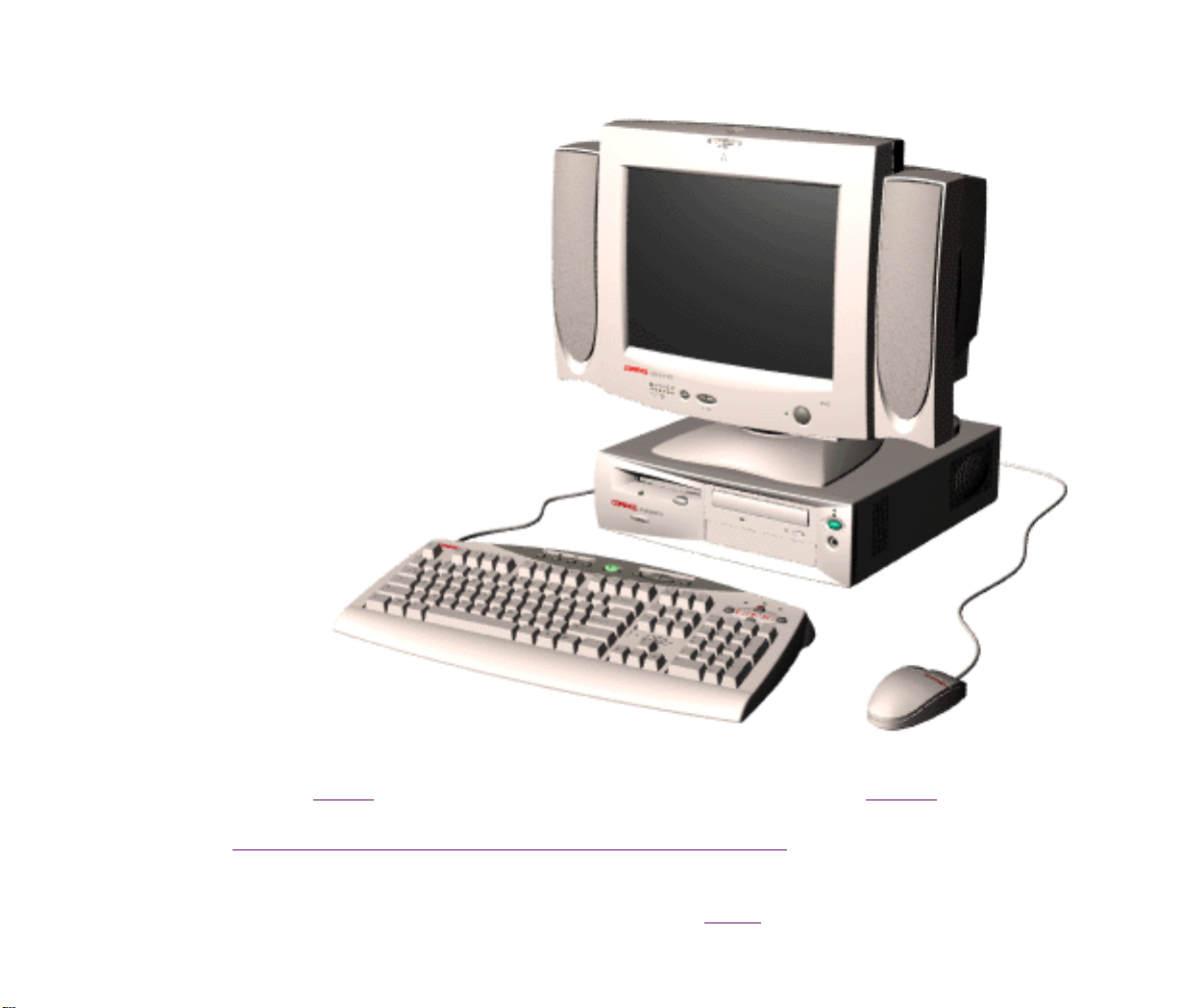
Maintenance and Service Guide
Compaq 2200 and 2400 Series Computers
See the Notice for copyright and trademark information, and the Preface for symbol
conventions and Technician Notes.
Download ZIP file of complete MSG onto local hard drive.
This MSG will be periodically maintained and updated as needed.
To report a technical problem, contact your Regional Support Center or IM Help Center.
For content comments or questions, contact the Editor.
Page 2

NOTICE
The information in this guide is subject to change without notice.
COMPAQ COMPUTER CORPORATION SHALL NOT BE LIABLE FOR TECHNICAL OR EDITORIAL ERRORS OR OMISSIONS
CONTAINED HEREIN, NOR FOR INCIDENTAL OR CONSEQUENTIAL DAMAGES RESULTING FROM THE FURNISHING,
PERFORMANCE, OR USE OF THIS MATERIAL.
This guide contains information protected by copyright. No part of this guide may be photocopied or reproduced in
any form without prior written consent from Compaq Computer Corporation. © 1998 Compaq Computer Corporation.
All rights reserved. Compaq, Presario Registered U. S. Patent and Trademark Office.
Microsoft, MS-DOS, and Windows are registered trademarks of Microsoft Corporation. Windows 95 is a trademark of
Microsoft Corporation. The software described in this guide is furnished under a license agreement or nondisclosure
agreement. The software may be used or copied only in accordance with the terms of the agreement. Product names
mentioned herein may be trademarks and/or registered trademarks of their respective companies.
Online Maintenance and Service Guide
Compaq 2200 and 2400 Series Computers
August 1998
Page 3
PREFACE
This Maintenance and Service Guide is a troubleshooting guide that can be used for reference when servicing the
Compaq 2200 and 2400 Series Computers.
Compaq Computer Corporation reserves the right to make changes to the Compaq 2200 and 2400 Series Computers
without notice.
Symbols
The following words and symbols mark special messages throughout this guide.
WARNING: Text set off in this manner indicates that failure to
follow directions in the warning could result in bodily harm or loss
of life.
CAUTION: Text set off in this manner indicates that failure to
follow directions could result in damage to equipment or loss of
data.
IMPORTANT: Text set off in this manner presents clarifying information or specific
NOTE:
Text set off in this manner presents commentary, sidelights, or interesting points of
information.
Technician Notes
WARNING: Only authorized technicians trained by Compaq should repair
this equipment. All troubleshooting and repair procedures are detailed to
allow only subassembly/module level repair. Because of the complexity of the
individual boards and subassemblies, the user should not attempt to make
repairs at the component level or to make modifications to any printed circuit
board. Improper repairs can create a safety hazard. Any indications of
component replacement or printed circuit board modifications may void any
warranty.
instructions.
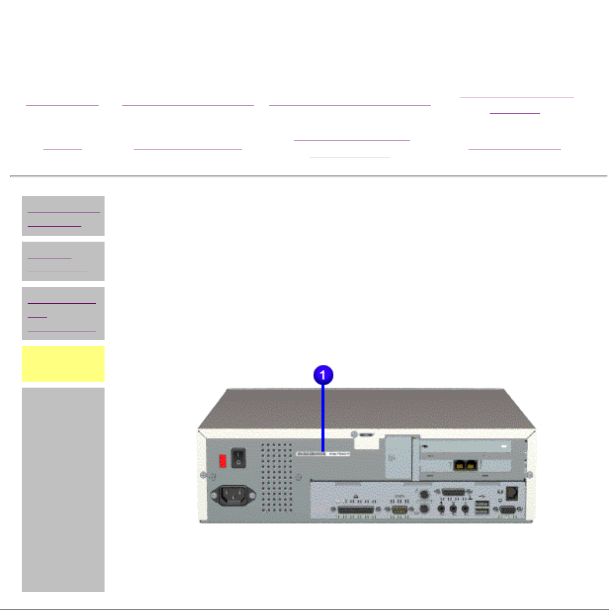
Serial Number
When requesting information or ordering spare parts, the computer serial number should be provided to Compaq.
This can be found on the rear of the computer to the right of the power supply vent.
Locating Additional Information
The following documentation is available to support this product:
■ Compaq Presario documentation set
■ Introducing Windows 95 Guide
■ Service Training Guides
■ Compaq Service Advisories and Bulletins
■ Compaq QuickFind
■ Compaq Service Quick Reference Guide
■ Compaq Help Center
Page 4
Maintenance and Service Guide
Compaq 2200 and 2400 Series Computers
MSG Index Product Description Removal & Replacement
Home Troubleshooting
Electrostatic
discharge
REMOVAL & REPLACEMENT
Jumper & Switch
Information
Preliminary Considerations
Service
particulars
Preparation
for
disassembly
Serial
number
Serial Number
The computer serial number should be provided to Compaq whenever
requesting information or ordering spare parts. The serial number is located on
the rear of the unit, to the right of the power supply vent.
Illustrated Parts
Catalog
Specifications
Page 5
Maintenance and Service Guide
Compaq 2200 and 2400 Series Computers
MSG Index Product Description Removal & Replacement Illustrated Parts Catalog
Home Troubleshooting Jumper & Switch Information Specifications
Electrostatic
discharge
Service
particulars
Preparation
for
disassembly
Serial
number
REMOVAL & REPLACEMENT
Preliminary Considerations
Electrostatic Discharge
A sudden discharge of static electricity from a finger or other conductor can destroy static-sensitive
devices or microcircuitry. Often the spark is neither felt nor heard, but damage occurs. An electronic
device exposed to electrostatic discharge (ESD) may not be affected at all and will work perfectly
throughout a normal cycle. Or it may function normally for a while, then degrade in the internal layers,
reducing its life expectancy.
Networks built into many integrated circuits provide some protection, but in many cases, the discharge
contains enough power to alter device parameters or melt silicon junctions.
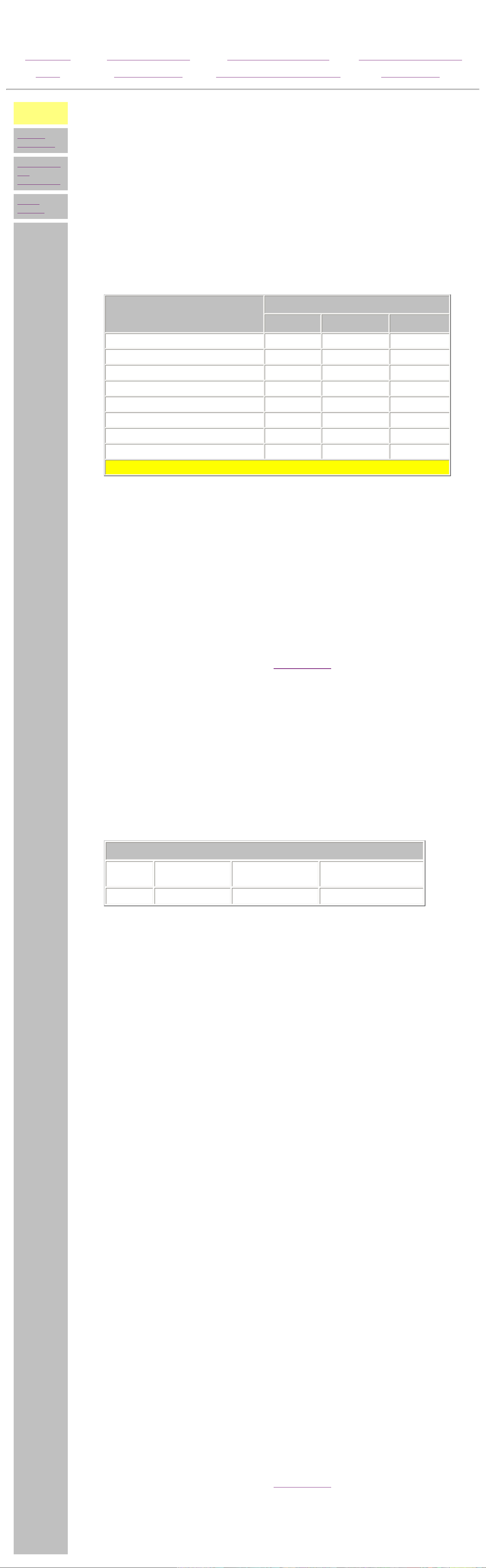
Generating Static
The table below shows the different amounts of static electricity generated by different activities .
Event
Walking across carpet 35,000 V 15,000 V 7,500 V
Walking across vinyl floor 12,000 V 5,000 V 3,000 V
10%
Relative Humidity
40% 55%
Motions of bench worker 6,000 V 800 V 400 V
Removing DIPS from plastic tubes 2,000 V 700 V 400 V
Removing DIPS from vinyl trays 11,500 V 4,000 V 2,000 V
Removing DIPS from Styrofoam 14,500 V 5,000 V 3,500 V
Removing bubble pack from PCBs 26,000 V 20,000 V 7,000 V
Packing PCBs in foam-lined box 21,000 V 11,000 V 5,000 V
NOTE: 700 volts can degrade a product!
Preventing Electrostatic Damage to Equipment
Many electronic components are sensitive to ESD. Circuitry design and structure determine the degree of
sensitivity. The following proper packaging and grounding precautions are necessary to prevent damage:
■ Protect all electrostatic parts and assemblies with conductive or approved containers
or packaging.
■ Keep electrostatic sensitive parts in their containers until they arrive at static-free
stations.
■ Place items on a grounded surface before removing them from their container.
■ Always be properly grounded when touching a sensitive component or assembly.
■ Place reusable electrostatic-sensitive parts from assemblies in protective packaging
or conductive foam.
Use transporters and conveyors made of antistatic belts and metal roller bushings. Mechanized
equipment used for moving materials must be wired to ground and proper materials selected to avoid
static charging. When grounding is not possible, use an ionizer to dissipate electric charges.
Return to the
top of the page.
Preventing Damage to Drives
To prevent static damage to hard drives, use the following precautions:
■ Handle drives gently, using static-guarding techniques.
Grounding Methods
The method for grounding must include a wrist strap or a foot strap at a grounded workstation. When
seated, wear a wrist strap connected to a grounded system. When standing, use footstraps and a
■ Store drives in the original shipping containers.
■ Avoid dropping drives from any height onto any surface.
■ Handle drives on surfaces that have at least one inch of shock-proof foam.
■ Always place drives PCB assembly side down on the foam.
grounded floor mat.
Static-Shielding Protection Levels
Method
Grounding Workstations
To prevent static damage at the workstation, use the following precautions:
Voltages
■ Cover the workstation with approved static-dissipative material. Provide a wrist strap
Antistatic Plastic Carbon-Loaded
Plastic
1,500 7,500 15,000
Metallized Laminate
connected to the work surface and properly grounded tools and equipment.
■ Use static-dissipative mats, heel straps, or air ionizers to give added protection.
■ Handle electrostatic sensitive components, parts, and assemblies by the case or PCB
laminate. Handle them only at static-free workstations.
■ Avoid contact with pins, leads, or circuitry.
■ Turn off power and input signals before inserting and removing connectors or test
equipment.
■ Use fixtures made of static-safe materials when fixtures must directly contact
dissipative surfaces.
■ Keep work area free of nonconductive materials such as ordinary plastic assembly
aids and Styrofoam.
■ Use field service tools, such as cutters, screwdrivers, and vacuums, that are
conductive.
■ Use a portable field service kit with a static dissipative vinyl pouch that folds out of a
work mat. Also use a wrist strap and a ground cord for the work surface. Ground the
cord to the chassis of the equipment undergoing test or repair.
Grounding Equipment
Use the following equipment to prevent static electricity damage to the equipment:
Wrist Straps are flexible straps with a minimum of 1 megohm ±10% resistance to the ground cords. To
provide proper ground, a strap must be worn snug against the skin. On grounded mats without bananaplug connectors, connect a wrist strap with alligator clips.
Heelstraps/Toestraps/Bootstraps can be used at standing workstations and are compatible with most
types of boots and shoes. On conductive floors or dissipative floor mats, use them on both feet with a
minimum of 1 megohm resistance between operator and ground. To be effective, the conductive strips
must be worn in contact with the skin.
Recommended Materials and Equipment
Other materials and equipment that are recommended for use in preventing static electricity include:
■ Antistatic tape
■ Antistatic smocks, aprons, or sleeve protectors
■ Conductive bins, and other assembly or soldering aids
■ Conductive foam
■ Conductive tabletop workstations with ground cord of 1 megohm of resistance
■ Static dissipative table or floor mats with hard tie to ground
■ Field service kits
■ Static awareness labels
■ Wrist straps and footwear straps providing 1 megohm ±10% resistance
■ Material handling packages
■ Conductive plastic bags
■ Conductive plastic tubes
■ Conductive tote boxes
■ Metal tote boxes
■ Opaque shielding bags
■ Transparent metallized shielding bags
■ Transparent shielding tubes
Return to the
top of the page.
Page 6
Maintenance and Service Guide
Compaq 2200 and 2400 Series Computers
MSG Index Product Description Removal & Replacement Illustrated Parts Catalog
Home Troubleshooting Jumper & Switch Information Specifications
Electrostatic
discharge
Service
particulars
Preparation
for
disassembly
Serial
number
REMOVAL & REPLACEMENT
Preliminary Considerations
Service Particulars
Listed below are some details that should be kept in mind during the disassembly and reassembly of the
computer.
Tool Requirements
■ Phillips screwdriver
■ Needle-nose pliers
■ Flat-bladed screwdriver
■ Compaq Utilities software
Screws
The screws used in these products are not interchangeable. If an incorrect screw is used during the
reassembly process, it could cause damage to the unit. Compaq strongly recommends that all screws
removed during the disassembly process be kept with the part that was removed, then returned to their
proper locations.
IMPORTANT: As each subassembly is removed from the computer, it should
be placed away from the work area to prevent damage.
Cables and connectors
Most cables used throughout the unit are ribbon cables. These must be handled with extreme care to
avoid damage. Apply only the tension required to seat or unseat the cables during insertion or removal
from the connector. Handle cables by the connector whenever possible. In all cases, avoid bending,
twisting, or tearing the cables, and ensure that they are placed in such a way that they cannot be caught
or snagged by parts being removed or replaced.
l
CAUTION: When servicing these computers, ensure that cables
are placed in their proper location during the reassembly process.
Improper cable placement can cause severe damage to the unit.
Ribbon Cable Positions
● CD drive
● Diskette drive
● Hard drive
Page 7
Maintenance and Service Guide
Compaq 2200 and 2400 Series Computers
MSG Index Product Description Removal & Replacement Illustrated Parts Catalog
Home Troubleshooting Jumper & Switch Information Specifications
CD drive
Diskette drive
Hard drive
Service
considerations
index page
l
REMOVAL & REPLACEMENT
Preliminary Considerations
Service Considerations - Cable Positions
CD drive (and hard drive)
This cable connects to J10 on the system board.
Page 8
Maintenance and Service Guide
Compaq 2200 and 2400 Series Computers
MSG Index Product Description Removal & Replacement Illustrated Parts Catalog
Home Troubleshooting Jumper & Switch Information Specifications
CD drive
Diskette drive
Hard drive
Service
considerations
index page
l
REMOVAL & REPLACEMENT
Preliminary Considerations
Service Considerations - Cable Positions
Diskette drive
This cable connects to J2 on the system board.
Page 9
Maintenance and Service Guide
Compaq 2200 and 2400 Series Computers
MSG Index Product Description Removal & Replacement Illustrated Parts Catalog
Home Troubleshooting Jumper & Switch Information Specifications
CD drive
Diskette drive
Hard drive
Service
considerations
index page
l
REMOVAL & REPLACEMENT
Preliminary Considerations
Service Considerations - Cable Positions
Hard drive (and CD drive)
This cable connects to J10 on the system board.
Page 10
Maintenance and Service Guide
NCtion.gif
Compaq 2200 and 2400 Series Computers
MSG Index Product Description Removal & Replacement Illustrated Parts Catalog
Home Troubleshooting Jumper & Switch Information Specifications
Electrostatic
discharge
Service
particulars
Preparation
for
disassembly
Serial
number
REMOVAL & REPLACEMENT
Preliminary Considerations
Preparation for Disassembly
To prepare the computer for removal and replacement procedures, please complete these
steps:
1 Remove any diskette, compact disc, or tape from the computer.
2 Close all programs, shut down the computer, and turn off the power switch.
3 Turn off any peripheral devices that are connected to the computer.
CAUTION: The computer power switch must be turned off
before disconnecting any cables.
4 Disconnect the power cord from the electrical outlet, and then from the computer.
WARNING: Do not open the hood until after the power cable has been
removed from the electrical outlet.
5 Disconnect all peripheral device cables from the computer.
IMPORTANT: During disassembly, label each cable as you remove
it. Be sure to note its position and routing.
Page 11

Maintenance and Service Guide
Compaq 2200 and 2400 Series Computers
MSG Index Product Description
Home Troubleshooting
PRODUCT DESCRIPTION INDEX PAGE
Models & model-specific features
CPU controls & lights Rear components,
Keyboard controls & lights Power cord set
Removal &
Replacement
Jumper & Switch
Information
connector pin assignments
requirements,
general requirements
country-specific requirements
Illustrated Parts
Catalog
Specifications
Page 12
--2262--------------------MX (300)-------------------------4.0------------------------------32-------------------------yes---
--2264--------------------MX (300)-------------------------4.0------------------------------32--------------------------no---
--2266--------------------MX (300)-------------------------4.0------------------------------64--------------------------no---
--2268--------------------MX (300)-------------------------4.0------------------------------64--------------------------no---
--2275-------------------K6-2 (333)------------------------6.0------------------------------64--------------------------no---
--2260--------------------MX (300)-------------------------2.1-------------------------32--------------------------no-----
--2262--------------------MX (300)-------------------------2.1-------------------------32--------------------------no-----
--2274-------------------K6-2 (300)------------------------4.0-------------------------48--------------------------no-----
--2280--------------------M2 (333)-------------------------3.2-------------------------32--------------------------no-----
--2282--------------------M2 (333)-------------------------3.2-------------------------32--------------------------no-----
--2260--------------------MX (300)-------------------------2.1------------------------------32--------------------------no---
--2262--------------------MX (300)-------------------------2.1---------------------------32,64------------------------yes---
--2270-------------------K6-2 (300)------------------------4.0------------------------------32--------------------------no---
--2274-------------------K6-2 (300)------------------------4.0------------------------------64--------------------------no---
--2276-------------------K6-2 (333)------------------------4.0------------------------------48-------------------------yes---
Maintenance and Service Guide
Compaq 2200 and 2400 Series Computers
MSG Index Product Description Removal & Replacement Illustrated Parts Catalog
Home Troubleshooting Jumper & Switch Information Specifications
Models and
features
CPU controls
and lights
Keyboard
controls and
lights
Rear CPU
connectors
Power cord
set
requirements
PRODUCT DESCRIPTION
Models and Model-Specific Features
Compaq 2200 and 2400 Series Computers
Standard Configurations
Please Note:
All models have 512kB L2 cache and a 32x CD drive.
U.S., Latin America, Canada
Model Processor (MHz)* Hard Drive (GB) SDRAM (MB) NIC
Europe, Middle East, Africa
Model Processor
(MHz)*
Hard Drive
(GB)
SDRAM (MB) NIC
Asia/Pacific, Japan
Model Processor (MHz)* Hard Drive (GB) SDRAM (MB) NIC
*Megahertz-equivalent performance level. Based upon industry-standard benchmark
comparisons to the Pentium© II processor when tested in equivalently configured computer
systems.
Page 13

Maintenance and Service Guide
Compaq 2200 and 2400 Series Computers
MSG Index Product Description Removal & Replacement
Home Troubleshooting
Models and
features
PRODUCT DESCRIPTION
Jumper & Switch
Information
CPU Controls and Lights
CPU controls
and lights
Keyboard
controls and
lights
Rear CPU
connectors
Illustrated Parts
Catalog
Specifications
Floppy
drive
1
activity
light
Floppy
drive
2
access
door
Power cord
set
requirements
FG
Floppy
diskette
3
eject
button
CD drive
activity
4
light
CD drive
tray access
5
door
Manual
6
eject slot
CD
load/eject
7
button
Hard drive
activity
8
light
Sleep
9
status light
Instant on
10
button
Headphone
11
socket
Page 14

Maintenance and Service Guide
Compaq 2200 and 2400 Series Computers
MSG Index Product Description Removal & Replacement Illustrated Parts Catalog
Home Troubleshooting Jumper & Switch Information Specifications
Models and
features
CPU controls
and lights
Keyboard
controls
and lights
Rear CPU
connectors
Power cord
set
requirements
PRODUCT DESCRIPTION
Keyboard Controls and Lights
1 Play/pause
2 Stop
3 Previous track
4 Next track
5 Sleep button
6 Mute
7 Volume down
8 Volume up
9 Favorite application
launch
● Click here for the top center of Space Saver keyboard.
● Click here for the top right corner of the Easy Access
Internet keyboard.
Page 15
Maintenance and Service Guide
Compaq 2200 and 2400 Series Computers
MSG Index Product Description Removal & Replacement Illustrated Parts Catalog
Home Troubleshooting Jumper & Switch Information Specifications
Models and
features
CPU controls
and lights
Keyboard
controls
and lights
Rear CPU
connectors
Power cord
set
requirements
PRODUCT DESCRIPTION
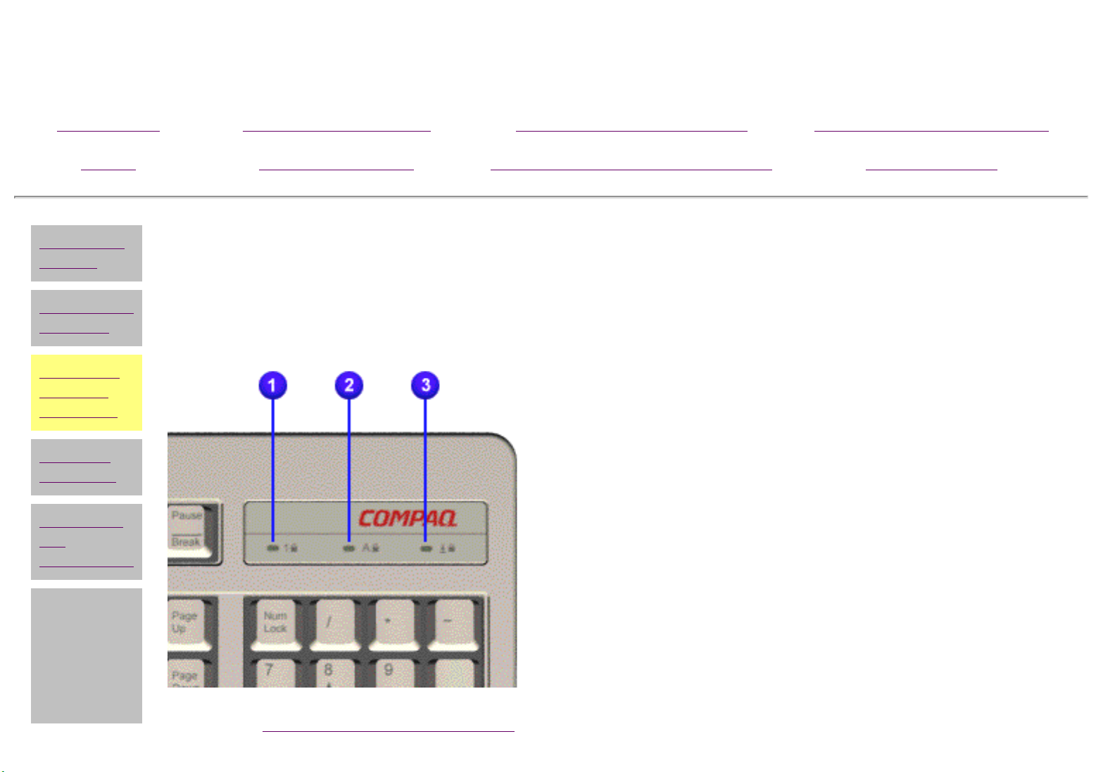
Keyboard Controls and Lights
Space Saver Keyboard
1 Num Lock Light
2 Caps Lock Light
3 Scroll Lock Light
l
go back to Keyboard controls & lights
main page.
Page 16
Maintenance and Service Guide
Compaq 2200 and 2400 Series Computers
MSG Index Product Description Removal & Replacement Illustrated Parts Catalog
Home Troubleshooting Jumper & Switch Information Specifications
Models and
features
CPU controls
and lights
Keyboard
controls
and lights
Rear CPU
connectors
Power cord
set
requirements
l
PRODUCT DESCRIPTION
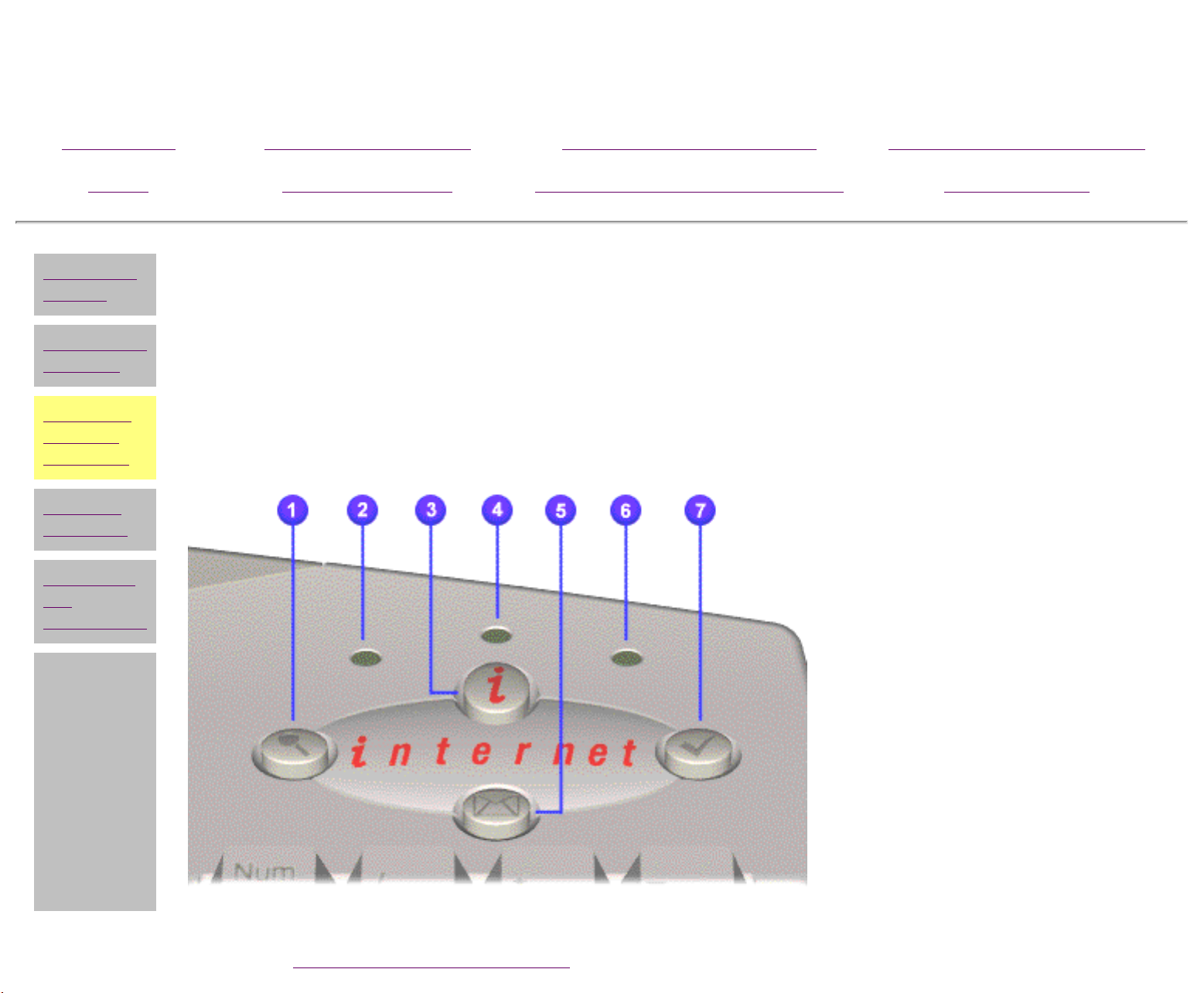
Keyboard Controls and Lights
Easy Access Internet Keyboard
Upper right corner
1 Instant search
2 Num lock light
3 Instant Internet
4 Caps lock light
5 Instant e-mail
6 Scroll lock light
7 Featured Web site
go back to Keyboard controls & lights main page
Page 17
Maintenance and Service Guide
NCtion.gif
Compaq 2200 and 2400 Series Computers
MSG Index Product Description Removal & Replacement Illustrated Parts Catalog
Home Troubleshooting Jumper & Switch Information Specifications
Models and
features
CPU controls
and lights
Keyboard
controls and
lights
CPU rear
connectors
Power cord
set
requirements
PRODUCT DESCRIPTION
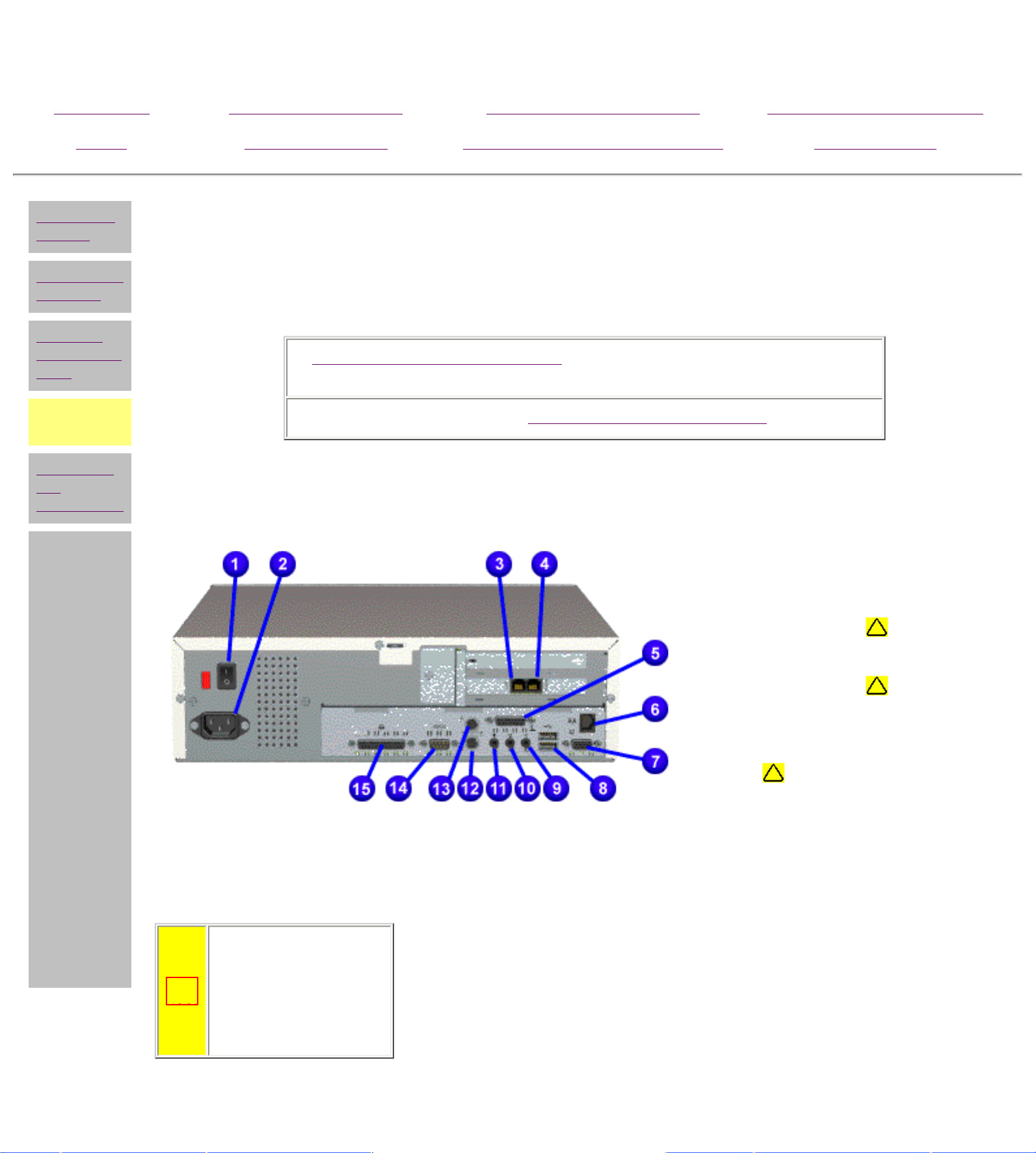
CPU Rear Connectors-2200 Series Models
Click the appropriate link:
Rear connector assignments for Educational Models 2412ES &
2416ES.
or 2200 series
Connector pin assignments.
1
Main power switch (on/off)
2
AC power inlet
Modem or phone
3
varies)
Modem or phone (location
4
varies)
5
MIDI/gamepad/joystick
6
NIC
7
VGA monitor
(on select models)
(location
8
USB (2 connectors)
9
Speaker out
10
Audio line out
CAUTION: Do not
plug a phone line
into the network
connector, it may
damage the
computer.
11
Microphone
12
Keyboard
13
Mouse
14
Serial port
15
Parallel/printer port
Page 18

Maintenance and Service Guide
NCtion.gif
Compaq 2200 and 2400 Series Computers
MSG Index Product Description Removal & Replacement Illustrated Parts Catalog
Home Troubleshooting Jumper & Switch Information Specifications
Models and
features
CPU controls
and lights
Keyboard
controls and
lights
CPU rear
connectors
Power cord
set
requirements
PRODUCT DESCRIPTION
CPU Rear Connectors- 2412ES & 2416ES Models
1
Main power switch (on/off)
2
AC power inlet
3
NIC
4
MIDI/gamepad/joystick
5
VGA monitor
6
USB (2 connectors)
7
Speaker
8
Audio line out
(location may vary)
Click here to see the connector pin assignments .
or here to go back to
CPU rear connectors main page.
CAUTION: Do not plug a phone line into the network
connector, it may damage the computer
9
Microphone
10
Keyboard
11
Mouse
12
Serial port
13
Parallel/printer port
Page 19

Maintenance and Service Guide
Compaq 2200 and 2400 Series Computers
MSG Index Product Description Removal & Replacement Illustrated Parts Catalog
Home Troubleshooting
Models and
features
PRODUCT DESCRIPTION
CPU Rear Connectors
CPU controls
and lights
Keyboard
controls and
lights
CPU rear
connectors
Power cord
set
requirements
Connector Pin Assignments
Click on an item to see its pin assignments:
Audio line out
Audio line in Keyboard Parallel
Jumper & Switch
Specifications
Information
Flat panel
Mouse Serial
monitor
Speaker / headphone
out
CD drive data
l
cable
Fax/modem MIDI/joystick
Microphone Phone line to phone USB
Phone line to wall
VGA monitor
jack
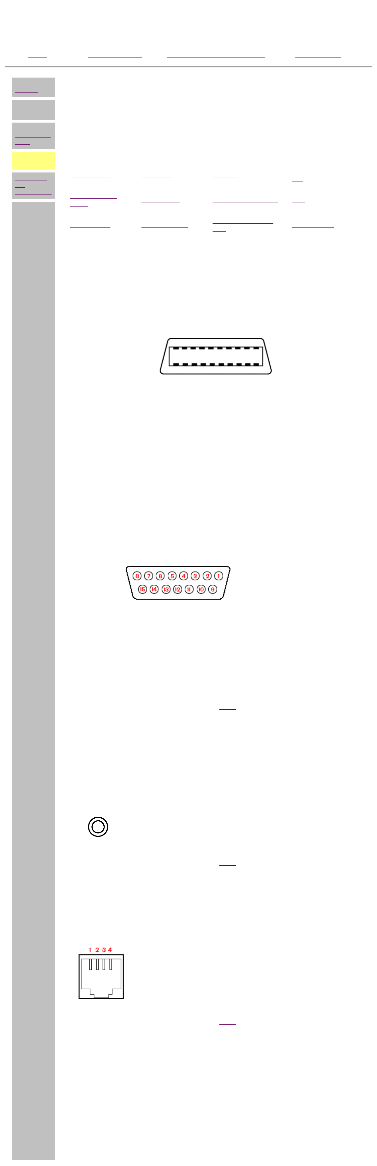
Parallel Connector
Pin Signal Pin Signal Pin Signal
1
Strobe*
7
Data Bit 5
13
Select
2
3
4
5
Data Bit 0
Data Bit 1
Data Bit 2
Data Bit 3
8
9
10
11
Data Bit 6
Data Bit 7
Acknowledge*
Busy
14
15
16
17
Auto Linefeed*
Error*
Initialize Printer*
Select In*
6
Data Bit 4
12
Paper Out
1825
Signal Ground
* Active low
Return to
the top.
Serial Connector
Pin Signal
1
2
3
Carrier Detect
Receive Data
Transmit Data
4
Data Terminal Ready
5
6
7
8
Signal Ground
Data Set Ready
Ready to Send
Clear to Send
9
Ring Indicator
Return to
the top.
Universal Serial Bus
Pin Signal
1
- Data
Keyboard &
2
3
4
+Data
Ground
+5 VDC
Return to
the top.
Mouse
Pin Signal
1
2
Data
Unused
3
4
Ground
+5 VDC
5
6
Clock
Unused
Page 20
Maintenance and Service Guide
Compaq 2200 and 2400 Series Computers
MSG Index Product Description Removal & Replacement Illustrated Parts Catalog
Home Troubleshooting Jumper & Switch Information Specifications
Models and
features
CPU controls
and lights
Keyboard
controls and
lights
CPU rear
connectors
Power cord
set
requirements
l
PRODUCT DESCRIPTION
CPU Rear Connectors
Connector Pin Assignments
Click on an item to see its pin assignments:
Audio line out Flat panel monitor Mouse Serial
Audio line in Keyboard Parallel
CD drive data
Microphone Phone line to phone USB
cable
Phone line to wall
Fax/modem MIDI/joystick
jack
Speaker/headphone
out
VGA monitor
Flat-panel monitor
Pin Signal Pin Signal Pin Signal Pin Signal
1
2
3
TX2+
Ground
TX1+
6
7
8
TXC+
Logic ground
DDC data (SDA)
11
12
13
TX2Ground
TX1-
16
17
18
TXC+5VDC
DDC Clock (SCL)
4
5
TX0+
Ground
9
10
Reserved
Reserved
14
15
TX0Ground
19
20
Reserved
Reserved
Return to
the top.
MIDI/Joystick
Pin Signal Pin Signal Pin Signal
1
2
3
4
+5 VDC
Fire A (1)
X-Axis (1)
Ground
6
7
8
9
Y-Axis (1)
Fire B (1)
+5 VDC
+5 VDC
11
12
13
14
X-Axis (2)
MIDI Out
Y-Axis (2)
Fire B (2)
5
Ground
10
Fire A (2)
15
MIDI In
Return to
the top.
Line out
Line in
Speaker/Headphone Out
Microphone
Stereo 1/8"
Miniphone
Return to
the top.
Phone Line to Wall Jack
Phone Line to Phone
Pin Signal
1
2
Unused
Tip
3
Ring
4
Unused
Return to
the top.
Pin Signal Pin Signal Pin Signal
Internal Fax/Modem
1
2
Unused
Unused
3
4
Ring
Tip
5
6
Unused
Unused
Page 21
Maintenance and Service Guide
Compaq 2200 and 2400 Series Computers
MSG Index Product Description Removal & Replacement Illustrated Parts Catalog
Home Troubleshooting Jumper & Switch Information Specifications
Models and
features
CPU controls
and lights
Keyboard
controls and
lights
CPU rear
connectors
Power cord
set
requirements
l
PRODUCT DESCRIPTION
CPU Rear Connectors
Connector Pin Assignments
Click on an item to see its pin assignments:
Audio line out Flat panel monitor Mouse Serial
Audio line in Keyboard Parallel
CD drive data
Microphone Phone line to phone USB
cable
Phone line to wall
Fax/modem MIDI/joystick
jack
Speaker/headphone
out
VGA monitor
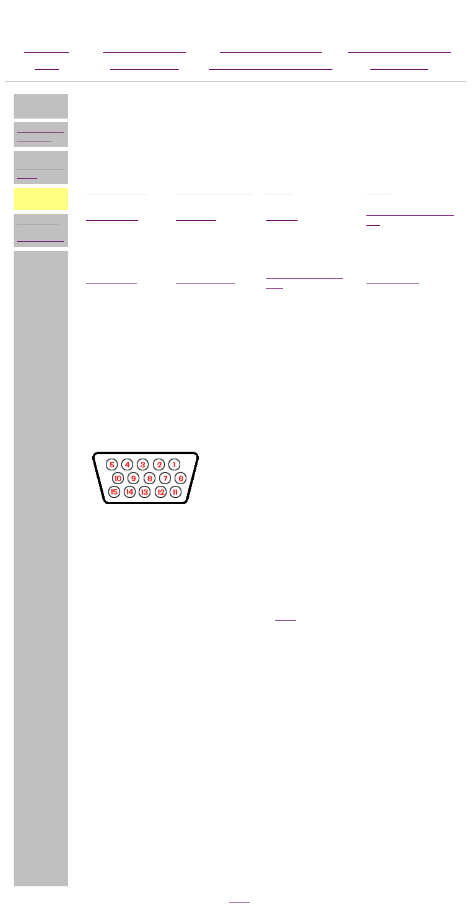
VGA Monitor
Pin Signal Pin Signal
1
2
3
Red Analog
Green Analog
Blue Analog
9
10
11
+5 VDC
Ground
Volume Down
4
5
6
7
8
Volume Up
Ground
Ground Analog
Ground Analog
Ground Analog
Return to
the top.
12
13
14
15
DDC Data
Horizontal Sync
Vertical Sync
DDC Clock
CD Drive Data Cable
Pin Signal Pin Signal Pin Signal Pin Signal
1
2
3
RESET
GND
DD7
11
12
13
DD3
DD12
DD2
21
22
23
DMARK
GND
-DIOW
31
32
33
INTRQ
-IOCS16
DA0
4
DD8
14
DD13
24
GND
34
-PDIA6
5
6
7
8
DD6
DD9
DD5
DD10
15
16
17
18
DD1
DD14
DD0
DD15
25
26
27
28
-DIOR
GND
IORDY
SPSYNC
35
36
37
38
DA0
DAZ
-CS1FX
-CS3FX
9
DD4
19
GND
29
-DMACK
39
-DASP
10
DD11
20
(KEY)
30
GND
40
GNP
Return to
the top.
Page 22

Maintenance and Service Guide
Compaq 2200 and 2400 Series Computers
MSG Index Product Description
Home Troubleshooting
Models and
features
PRODUCT DESCRIPTION
Power Cord Set Requirements
CPU controls
and lights
Keyboard
controls and
lights
Rear CPU
connectors
Power cord
set
requirements
● The auto-detect feature on the computer permits it to operate from any
line voltage between 120 and 240 volts AC.
● The power cord set (flexible cord and wall plug) received with the
computer meets the requirements for use in the country where the
computer was purchased.
● Power cord sets for use in other countries must meet the requirements
of the country where you use the computer. For more information on
power cord set requirements, contact your Compaq authorized dealer,
reseller, or service provider.
Removal &
Replacement
Jumper & Switch
Information
Illustrated Parts
Catalog
Specifications
l
General Requirements
The requirements listed below are applicable to all countries:
1
The length of the power cord set must be at least
6.00 feet (1.8 m) and a maximum of 9.75 feet (3.0
m).
2
All power cord sets must be approved by an
acceptable accredited agency responsible for
evaluation in the country where the power cord set
will be used.
3
The power cord set must have a minimum current
capacity of 10A and a nominal voltage rating of 125
or 250 volts AC, as required by each country's power
system.
4
The appliance coupler must meet the mechanical
configuration of an EN 60 320/IEC 320 Standard
Sheet C13 connector, for mating with appliance inlet
on the Switch Box.
Country-Specific Requirements
Country Accredited Agency
Australia EANSW* Italy IMQ*
Country Accredited
Agency
Austria OVE* Japan JIS***
Belgium CEBC* Norway NEMKO*
Canada CSA** Sweden SEMKO*
Denmark DEMKO* Switzerland SEV*
Finland SETI* United
Kingdom
BSI*
France UTE* United States UL**
Germany VDE*
* The flexible cord must be <HAR> Type HO3VV-F, 3conductor, 1.0 mm2 conductor size. Power cord set fittings
(appliance coupler and wall plug) must bear the certification
mark of the agency responsible for evaluation in the country
where it will be used.
** The flexible cord must be Type SJT-2 or equivalent, No. 18
AWG, 3-conductor. The wall plug must be a two-pole
grounding type with a NEMA 5-15P (15A, 125V) or NEMA 615P (15A, 250V) configuration.
*** The appliance coupler, flexible cord, and wall plug must
bear a "T" mark and registration number in accordance with
the Japanese Dentori Law. Flexible cord must be Type VCT or
VCTF, 3-conductor, 0.75mm2 conductor size. The wall plug
must be a two-pole type with a Japanese Industrial Standard
C8303 (15A, 125V) configuration.
Page 23

Maintenance and Service Guide
Compaq 2200 and 2400 Series Computers
MSG Index Product Description Removal & Replacement
Jumper & Switch
Home Troubleshooting
Information
Illustrated Parts
Catalog
Specifications
REMOVAL & REPLACEMENT PROCEDURES - INDEX PAGE
This section provides general service information for Compaq 2200 and 2400 Series
Computers.
Adherence to the procedures and precautions described in this section is essential
for safe and proper service.
Preliminary considerations
electrostatic discharge
service particulars
preparation for disassembly
serial number
Hood
Button / headphone board
Riser card (backplane)
Power supply
Mass storage devices
drive cage
CD drive
diskette drive
hard drive
expansion bay cover
Front bezel
Internal speakers (ES models)
Fax-modem
NIC card (Network Interface Connector
card)
System board components
battery
memory module
processor
I/O panel
system board
Page 24

Maintenance and Service Guide
Compaq 2200 and 2400 Series Computers
MSG Index Product Description Removal & Replacement
Jumper & Switch
Home Troubleshooting
Information
DISASSEMBLY
SEQUENCE
REMOVAL & REPLACEMENT PROCEDURES
Preliminary Considerations - Index Page
Preliminary
considerations
For maximum safety and efficiency, please read and understand these sections
Hood
Button board
Front bezel
before attempting to repair or replace any components.
Electrostatic discharge
Service particulars
Illustrated Parts
Catalog
Specifications
Speakers
Fax-modem
NIC card
Riser card
Mass storage
devices
Power supply
System board
components
Preparation for disassembly
Serial number
Page 25
Maintenance and Service Guide
Compaq 2200 and 2400 Series Computers
MSG Index Product Description Removal & Replacement Illustrated Parts Catalog
Home Troubleshooting Jumper & Switch Information Specifications
DISASSEMBLY
SEQUENCE
Preliminary
considerations
Hood
Button board
Front bezel
Speakers
Fax-modem
NIC card
Riser card
Mass storage
devices
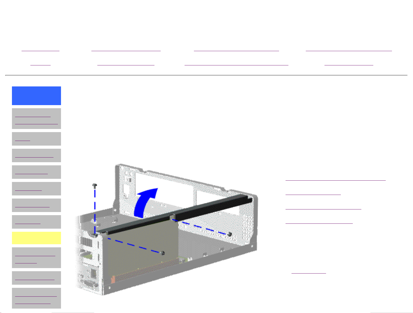
REMOVAL & REPLACEMENT
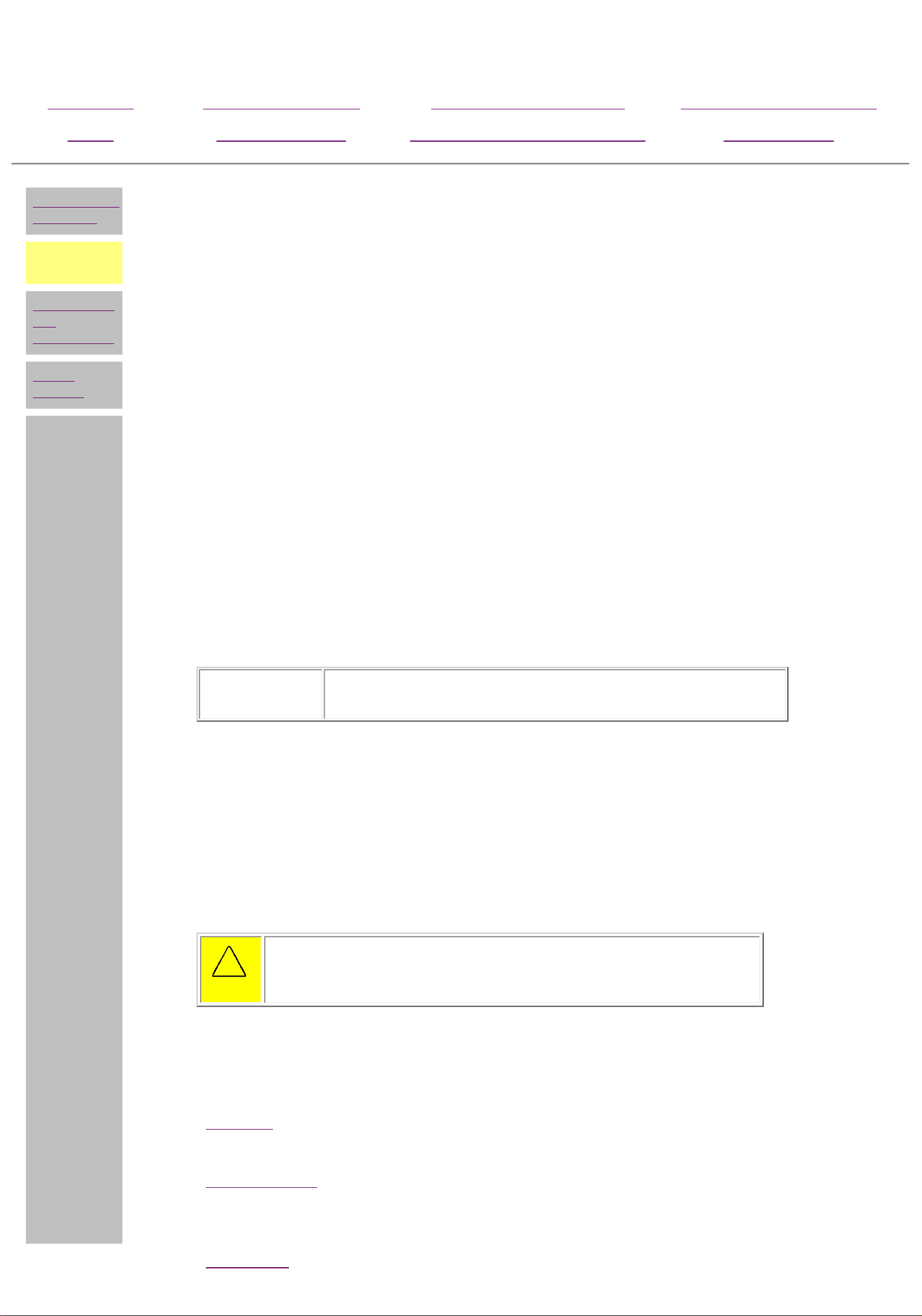
Riser Card (Backplane)
There are six steps in this sequence.
Perform preparation procedures.
1
Remove the hood.
2
Remove the fax-modem.
3
Remove the NIC card, if present.
4
Remove the three screws holding
5
the riser card to the cross-brace
bar.
Power supply
System board
components
NEXT STEP
Page 26
Maintenance and Service Guide
Compaq 2200 and 2400 Series Computers
MSG Index Product Description Removal & Replacement
Home Troubleshooting
Jumper & Switch
Information
REMOVAL &
REPLACEMENT
Riser Card (Backplane),
continued
Pull the riser card out of the
6
system board.
Illustrated Parts
Catalog
Specifications
END OF SEQUENCE
To replace the riser card, reverse
this sequence.
Return to section index
Page 27
Maintenance and Service Guide
Compaq 2200 and 2400 Series Computers
MSG Index Product Description Removal & Replacement Illustrated Parts Catalog
Home Troubleshooting Jumper & Switch Information Specifications
DISASSEMBLY
SEQUENCE
Preliminary
considerations
Hood
Button board
Front bezel
Speakers
Fax-modem
NIC card
Riser card
REMOVAL & REPLACEMENT
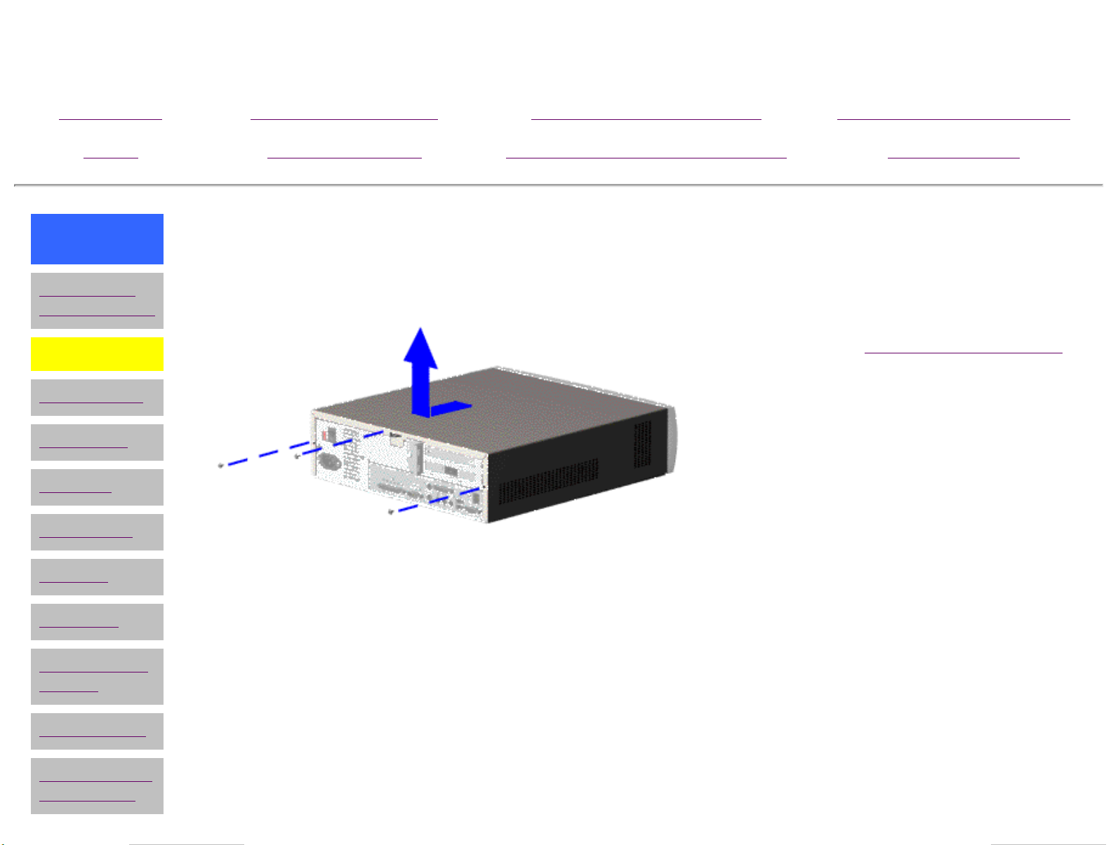
Hood
1
Perform the
2
Remove the three screws at the
preparation procedures
back of the computer which hold the
hood to the chassis
3
Grasp the handles on the bottom of
the hood, pull back slightly, and lift
the hood off the computer
To replace the hood, reverse this
sequence.
Mass storage
devices
Power supply
System board
components
Page 28

Maintenance and Service Guide
Compaq 2200 and 2400 Series Computers
MSG Index Product Description Removal & Replacement Illustrated Parts Catalog
Home Troubleshooting Jumper & Switch Information Specifications
DISASSEMBLY
SEQUENCE
Preliminary
considerations
Hood
Button board
Front bezel
Speakers
Fax-modem
NIC card
Riser card
REMOVAL & REPLACEMENT
Button / Headphone Board
1
Perform preparation procedures.
2
Remove the hood.
3
Disconnect the button board
cable from the system board (at
J27).
4
Remove the two screws from
the button board assembly.
5
Pull the assembly from the rear
of the front bezel.
Mass storage
devices
Power supply
System board
components
END OF SEQUENCE
To replace the button board assembly,
reverse this sequence.
Page 29

Maintenance and Service Guide
Compaq 2200 and 2400 Series Computers
MSG Index Product Description Removal & Replacement Illustrated Parts Catalog
Home Troubleshooting Jumper & Switch Information Specifications
DISASSEMBLY
SEQUENCE
Preliminary
considerations
Hood
Button board
Front bezel
Speakers
Fax-modem
NIC card
Riser card
REMOVAL & REPLACEMENT
Front Bezel
1
Perform preparation
procedures.
2
Remove the hood.
3
Remove the
button/headphone board.
4
Remove the drive cage.
5
Release the six latches, then
remove the front bezel from
the chassis.
Mass storage
devices
Power supply
System board
components
To replace the front bezel, reverse
this sequence.
Page 30

Maintenance and Service Guide
Compaq 2200 and 2400 Series Computers
MSG Index Product Description Removal & Replacement Illustrated Parts Catalog
Home Troubleshooting Jumper & Switch Information Specifications
DISASSEMBLY
SEQUENCE
Preliminary
considerations
Hood
Button board
Front bezel
Speakers
Fax-modem
NIC card
Riser card
REMOVAL & REPLACEMENT
Internal Speakers (ES models)
There are four steps in this
sequence.
Perform preparation
1
procedures.
Remove the hood.
2
Unplug the speaker cord from
3
the connector (J25 for L, J26
for R) on the system board.
NEXT STEP
Mass storage
devices
Power supply
System board
components
Page 31

Maintenance and Service Guide
Compaq 2200 and 2400 Series Computers
MSG Index Product Description Removal & Replacement Illustrated Parts Catalog
Home Troubleshooting Jumper & Switch Information Specifications
REMOVAL & REPLACEMENT
Internal Speakers (ES models), continued
Squeeze the plastic speaker casing at the bottom
4
(or squeeze the speaker tabs under the chassis), then
pull the speaker vertically out of the chassis .
END OF SEQUENCE
To replace a speaker, reverse this sequence.
Return to section index
Page 32

Maintenance and Service Guide
Compaq 2200 and 2400 Series Computers
MSG Index Product Description Removal & Replacement Illustrated Parts Catalog
Home Troubleshooting Jumper & Switch Information Specifications
DISASSEMBLY
SEQUENCE
Preliminary
considerations
Hood
Button board
Front bezel
Speakers
Fax-modem
NIC card
Riser card
REMOVAL & REPLACEMENT
Fax/modem
NOTE
Your modem may look
different and be in the upper
option slot.
1
Perform preparation procedures.
2
Remove the hood.
3
Remove the screw holding the option
card retainer bracket to the chassis.
4
Remove the option card retainer
bracket, then carefully pull the
fax/modem board out of the riser
card.
Mass storage
devices
Power supply
System board
components
l
To replace the fax/modem, reverse this
sequence.
IMPORTANT
When replacing the
fax/modem, download
the latest software from
SoftPaq. If QuickRestore
is used, it may not have
the 56K or V.90 upgrade
software included.
Page 33

Maintenance and Service Guide
Compaq 2200 and 2400 Series Computers
MSG Index Product Description Removal & Replacement Illustrated Parts Catalog
Home Troubleshooting Jumper & Switch Information Specifications
DISASSEMBLY
SEQUENCE
Preliminary
considerations
Hood
Button board
Front bezel
Speakers
Fax-modem
NIC card
Riser card
REMOVAL & REPLACEMENT
NIC card (2416ES models)
NOTE
Your NIC card may look
different and be in the upper
option slot
Perform preparation procedures.
1
Remove the hood.
2
Remove the screw holding the option
3
card retainer bracket to the chassis.
Remove the option card retainer
4
bracket, then carefully pull the NIC
card off the riser card.
Mass storage
devices
Power supply
System board
components
END OF SEQUENCE
To replace the NIC card, reverse this
sequence.
Page 34

Maintenance and Service Guide
Compaq 2200 and 2400 Series Computers
MSG Index Product Description Removal & Replacement Illustrated Parts Catalog
Home Troubleshooting Jumper & Switch Information Specifications
DISASSEMBLY
SEQUENCE
Preliminary
considerations
Hood
Button board
Front bezel
Speakers
Fax-modem
NIC card
Riser card
REMOVAL & REPLACEMENT
Mass Storage Devices - Index Page
The mass storage devices are located in a drive cage, which needs to be taken out of the
chassis before removing a drive.
Removing the drive cage
Hard drive
Diskette drive
CD drive
Expansion bay cover
Mass storage
devices
Power supply
System board
components
Page 35

Maintenance and Service Guide
Compaq 2200 and 2400 Series Computers
MSG Index Product Description Removal & Replacement Illustrated Parts Catalog
Home Troubleshooting
Drive cage
Diskette drive
Hard drive
CD drive
Expansion
bay
Mass storage
devices index
page
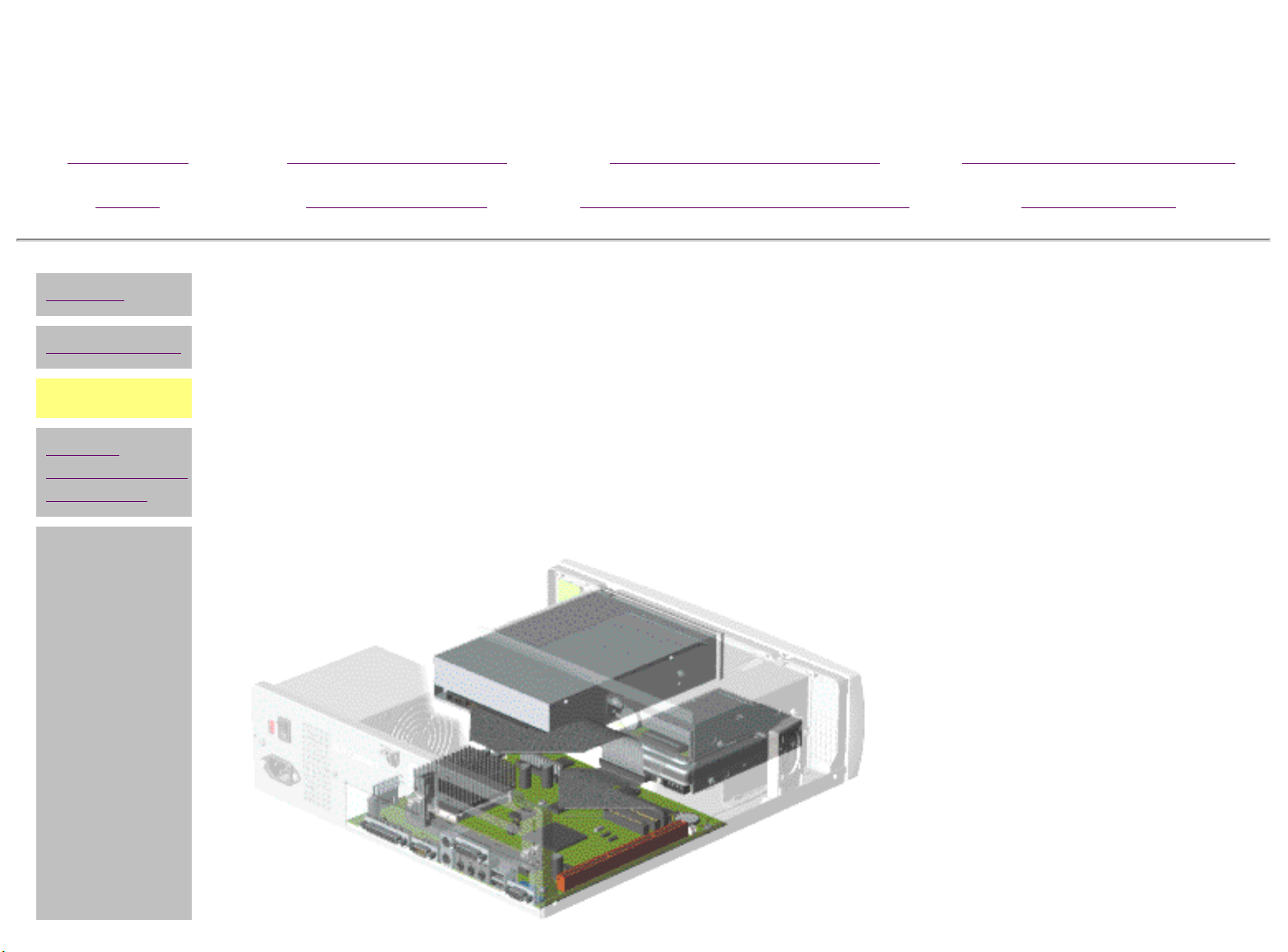
REMOVAL & REPLACEMENT
Mass Storage Devices
Removing the Drive Cage
Jumper & Switch
Information
Specifications
There are five steps in this sequence.
1
Perform preparation
procedures.
2
Remove the hood.
3
Disconnect the cables from the
diskette drive.
NEXT STEP
l
or Go back to Removal
and Replacement main
page.
Page 36

Maintenance and Service Guide
Compaq 2200 and 2400 Series Computers
MSG Index Product Description Removal & Replacement
Jumper & Switch
Home Troubleshooting
Information
REMOVAL &
REPLACEMENT
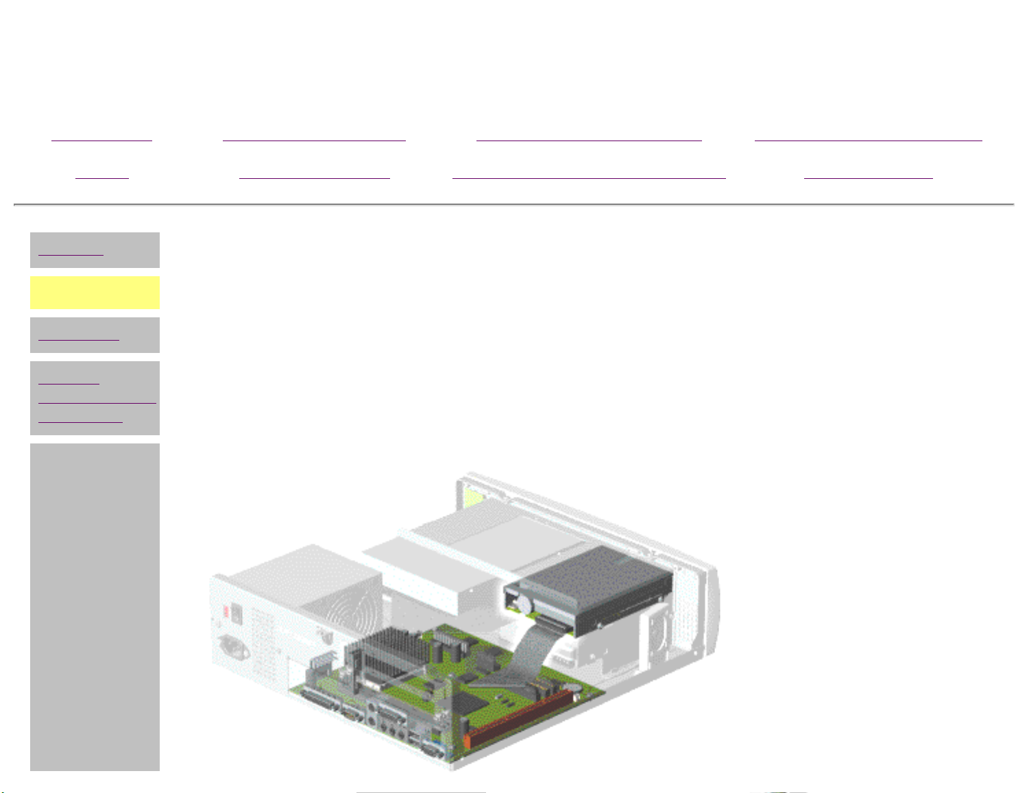
Mass Storage Devices
Removing the Drive Cage
(continued)
Illustrated Parts
Catalog
Specifications
Unplug the cables to the CD
4
drive and hard drive
NEXT STEP
Page 37

Maintenance and Service Guide
Compaq 2200 and 2400 Series Computers
MSG Index Product Description Removal & Replacement
Home Troubleshooting
Jumper & Switch
Information
REMOVAL &
REPLACEMENT
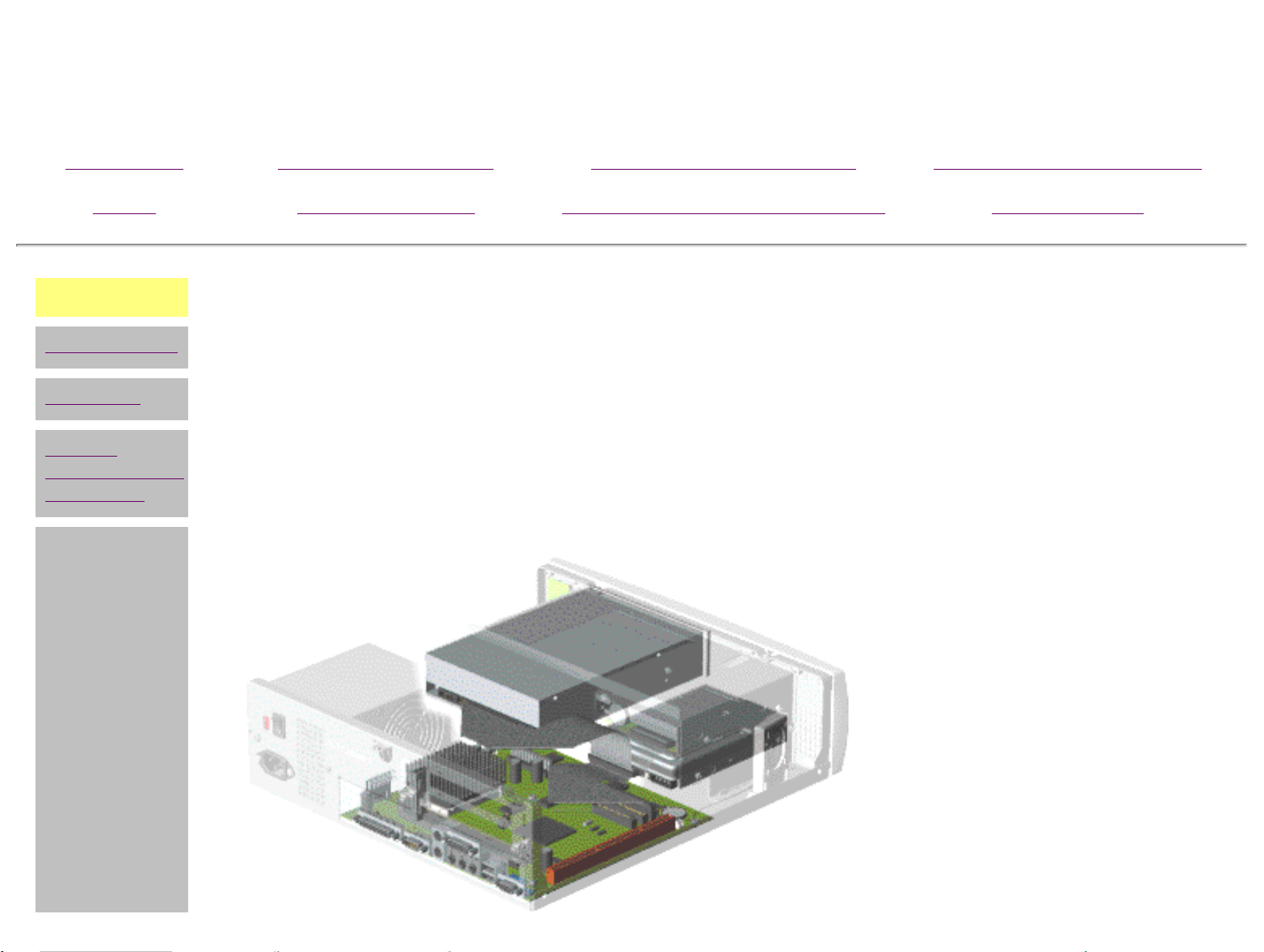
Mass Storage Devices
Removing the Drive Cage
(continued)
Remove the four screws
5
holding the drive cage to the
chassis, then slide the cage
toward the rear of the chassis
and lift out.
Illustrated Parts
Catalog
Specifications
END OF SEQUENCE
To replace the drive cage, reverse
this sequence.
Return to mass storage devices
index page
Page 38

Maintenance and Service Guide
Compaq 2200 and 2400 Series Computers
MSG Index Product Description Removal & Replacement Illustrated Parts Catalog
Home Troubleshooting Jumper & Switch Information Specifications
Drive cage
Diskette Drive
Hard drive
CD drive
Expansion bay
Mass storage
devices index
page
l
REMOVAL & REPLACEMENT
Mass Storage Devices
Hard Drive
There are seven steps in this
sequence.
1
Perform preparation
procedures.
2
Remove the hood.
3
Remove the drive cage from
the chassis.
4
Remove the CD drive.
5
Remove the two screws holding
the hard drive to the left side
of the cage.
NEXT STEP
Page 39

Maintenance and Service Guide
Compaq 2200 and 2400 Series Computers
MSG Index Product Description Removal & Replacement Illustrated Parts Catalog
Home Troubleshooting Jumper & Switch Information Specifications
REMOVAL & REPLACEMENT
Mass Storage Devices
Hard Drive, continued
6
Remove the recessed third screw, using an
8" magnetic Philips screwdriver.
7
Slide the drive out of the cage.
END OF SEQUENCE
To replace the hard drive, reverse this sequence.
Page 40

Maintenance and Service Guide
Compaq 2200 and 2400 Series Computers
MSG Index Product Description Removal & Replacement Illustrated Parts Catalog
Home Troubleshooting Jumper & Switch Information Specifications
Drive cage
Diskette drive
Hard drive
CD drive
Expansion bay
Mass storage
devices index
page
l
REMOVAL & REPLACEMENT
Mass Storage Devices
CD Drive
NOTE
1
Perform preparation
procedures.
2
Remove the hood.
3
Remove the drive cage from
the chassis.
Click
to remove a CD that
has jammed in the
drive.
here to see how
4
Remove the two screws
holding the CD drive in place,
then slide the drive out from
the front.
To replace the CD drive, reverse this
sequence.
END OF SEQUENCE
Page 41

Maintenance and Service Guide
Compaq 2200 and 2400 Series Computers
MSG Index Product Description Removal & Replacement
Home Troubleshooting
Drive cage
Diskette drive
Hard drive
CD drive
Expansion bay
Mass storage
devices index
page
l
REMOVAL & REPLACEMENT
Mass Storage Devices
Expansion Bay Cover
The expansion bay is used to hold extra drives, such as a Zip drive or an additional hard
drive.
Jumper & Switch
Information
Illustrated Parts
Catalog
Specifications
There are five
steps in this
sequence.
Perform
1
preparation
procedures.
Remove the
2
hood.
Remove the
3
drive cage.
Pull out the
4
plastic bay
cover.
NEXT
STEP
Page 42

Maintenance and Service Guide
Compaq 2200 and 2400 Series Computers
MSG Index Product Description Removal & Replacement
Home Troubleshooting
Jumper & Switch
Information
REMOVAL &
REPLACEMENT
Mass Storage Devices
Expansion Bay Cover
Pry out the metal bay cover
5
with a standard screwdriver
and discard it.
Illustrated Parts
Catalog
Specifications
END OF SEQUENCE
Return to index page
Page 43

Maintenance and Service Guide
Compaq 2200 and 2400 Series Computers
MSG Index Product Description Removal & Replacement Illustrated Parts Catalog
Home Troubleshooting Jumper & Switch Information Specifications
DISASSEMBLY
SEQUENCE
Preliminary
considerations
Hood
Button board
Front bezel
Speakers
Fax-modem
NIC card
Riser card
Mass storage
devices
REMOVAL & REPLACEMENT
Power Supply
1
Perform preparation
procedures.
2
Remove the hood.
3
Unplug all cables attached to
the power supply.
4
Remove the two screws that
secure the power supply to the
rear of the chassis.
NOTE
Your power supply
may look different
from the one
shown.
Power supply
System board
components
l
5
Slide the power supply back
and remove from the chassis.
END OF SEQUENCE
To replace the power supply, reverse
this sequence.
Page 44

Maintenance and Service Guide
Compaq 2200 and 2400 Series Computers
MSG Index Product Description Removal & Replacement Illustrated Parts Catalog
Home Troubleshooting Jumper & Switch Information Specifications
DISASSEMBLY
SEQUENCE
Preliminary
considerations
Hood
Button board
Front bezel
Speakers
Fax-modem
NIC card
Riser card
REMOVAL & REPLACEMENT
System Board Components - Index Page
● I/O panel
● Processor and heatsink
● Memory module
● RTC battery
● System board
Mass storage
devices
Power supply
System board
components
Page 45

Maintenance and Service Guide
Compaq 2200 and 2400 Series Computers
MSG Index Product Description Removal & Replacement Illustrated Parts Catalog
Home Troubleshooting Jumper & Switch Information Specifications
I-O panel
Processor
Memory
module
Battery
System
board
System
board
components
index page
l
REMOVAL & REPLACEMENT
System Board Components
I/O Panel
1
Perform preparation
procedures.
2
Remove the hood.
3
Remove the fax-modem.
4
Remove the NIC (if present).
5
Remove the riser card.
6
Remove the system board.
7
Remove the eight screws
holding the I/O panel to the
chassis.
8
Gently push the I/O panel into
the chassis and lift out.
To replace the I/O panel, reverse this
sequence.
Page 46

Maintenance and Service Guide
Compaq 2200 and 2400 Series Computers
MSG Index Product Description Removal & Replacement Illustrated Parts Catalog
Home Troubleshooting Jumper & Switch Information Specifications
I-O panel
Processor
Memory
module
Battery
System
board
System
board
components
index page
l
REMOVAL & REPLACEMENT
System Board Components
Processor and heatsink
1
Perform preparation procedures.
2
Remove the hood.
3
Remove the clip
.
4
Lift the heat sink
NOTE
The processor may come
out directly with the heat
sink.
from the heat sink
from the processor.
5
Raise the ZIF socket lever
processor out of the socket.
To reinstall the processor, rub a thermal
transfer crayon on the bottom of the
heatsink, then reverse the steps above.
(The thermal transfer crayon replaces the
thermal pad used with earlier processors.)
and lift the
Page 47

Maintenance and Service Guide
Compaq 2200 and 2400 Series Computers
MSG Index Product Description Removal & Replacement Illustrated Parts Catalog
Home Troubleshooting Jumper & Switch Information Specifications
I-O panel
Processor
Memory
module
Battery
System
board
System
board
components
index page
l
REMOVAL & REPLACEMENT
System Board Components
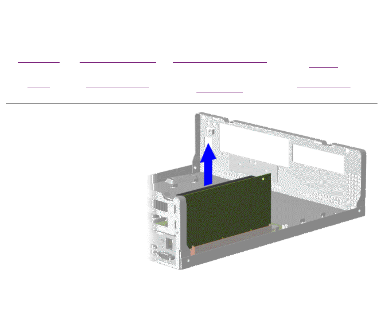
Memory Module (DIMM)
1
Perform preparation
procedures.
2
Remove the hood.
3
Remove the modem or NIC
card
4
Release the end latches of the
socket
DIMM from the system board
.
and unplug the
To replace the DIMM, reverse this
sequence.
Page 48

Maintenance and Service Guide
Compaq 2200 and 2400 Series Computers
MSG Index Product Description Removal & Replacement Illustrated Parts Catalog
Home Troubleshooting Jumper & Switch Information Specifications
I-O panel
Processor
Memory
module
Battery
System
board
System
board
components
index page
REMOVAL & REPLACEMENT
System Board Components
Battery
1
Perform preparation procedures.
2
Remove the hood.
3
Push out the battery socket latch and
lift the RTC battery out of the socket.
To replace the RTC battery, reverse this
sequence.
l
WARNING: The clock/CMOS
lithium battery may explode
if mistreated. Do not abuse.
Use only replacement
batteries supplied by Compaq
Computer Corporation.
Page 49

Maintenance and Service Guide
Compaq 2200 and 2400 Series Computers
MSG Index Product Description Removal & Replacement Illustrated Parts Catalog
Home Troubleshooting Jumper & Switch Information Specifications
I-O panel
Processor
Memory
module
Battery
System
board
System
board
components
index page
l
REMOVAL & REPLACEMENT
System Board Components
System Board
There are ten steps in this sequence.
1
Perform preparation
procedures.
2
Remove the hood.
3
Remove the fax-modem.
4
Remove the NIC card (if
present).
5
Remove the riser card.
6
Remove the drive cage.
7
Disconnect the
cable from J27.
8
If there are internal speakers,
disconnect the speaker cables
from J25 and J26.
button board
9
Disconnect the power, CD &
hard drive, and CD audio
cables.
NEXT STEP
Page 50

Maintenance and Service Guide
Compaq 2200 and 2400 Series Computers
MSG Index Product Description Removal & Replacement Illustrated Parts Catalog
Home Troubleshooting Jumper & Switch Information Specifications
REMOVAL & REPLACEMENT
System Board Components
System Board (continued)
10
Remove the four screws holding the system
board to the chassis, then slide the board away
from the I/O panel and lift it off the chassis.
END OF SEQUENCE
To replace the system board, reverse this sequence.
NOTE
The system board spare part kit does not
include the processor or DIMM. These
components must be transferred from the
old system board to the new system
board.
Page 51

Maintenance and Service Guide
Compaq 2200 and 2400 Series Computers
MSG Index Product Description Removal & Replacement Illustrated Parts Catalog
Home Troubleshooting Jumper & Switch Information Specifications
ILLUSTRATED PARTS CATALOG - INDEX PAGE
NOTE:
System unit
Mass storage devices
Cables
Processors & boards
Keyboards
The computer
requesting information or ordering spare parts.
serial number should be provided to Compaq whenever
Monitors
Miscellaneous parts
Return kits
Documentation & software
Page 52

Maintenance and Service Guide
Compaq 2200 and 2400 Series Computers
MSG Index Product Description Removal & Replacement Illustrated Parts Catalog
Home Troubleshooting Jumper & Switch Information Specifications
System unit
Mass storage
devices
Cables
Processors &
boards
Keyboards
Monitors
Miscellaneous
Return kits
Documentation
& software
ILLUSTRATED PARTS CATALOG
System Unit
To see the description and spare part number for an item, place your cursor over the item and leave
it there briefly.
l
Page 53

Maintenance and Service Guide
Hard drives:
Compaq 2200 and 2400 Series Computers
MSG Index Product Description Removal & Replacement Illustrated Parts Catalog
Home Troubleshooting Jumper & Switch Information Specifications
System unit
Mass storage
devices
Cables
Processors &
boards
Keyboards
Monitors
Miscellaneous
Return kits
Documentation
& software
l
ILLUSTRATED PARTS CATALOG
Mass Storage Devices
To see the description and spare part number for an item, place your cursor over the item and
leave it there briefly.
[FrontPage Save Results
Component]
Page 54

Maintenance and Service Guide
Asia/Pacific 137256-001
Australia 285811-001
Compaq 2200 and 2400 Series Computers
MSG Index Product Description Removal & Replacement Illustrated Parts Catalog
Home Troubleshooting Jumper & Switch Information Specifications
System unit
Mass storage
devices
Cables
Processors &
boards
Keyboards
Monitors
Miscellaneous
Return kits
Documentation
& software
ILLUSTRATED PARTS CATALOG
Cables
To see the description and spare part number for an item, place your cursor over the item and leave
it there briefly.
l
Page 55

Maintenance and Service Guide
100 MHz SDRAM DIMM:
56-DF V.90 fax-modems:
System boards:
Processors (heat sink and clip spared separately):
Riser Cards:
Compaq 2200 and 2400 Series Computers
MSG Index Product Description Removal & Replacement Illustrated Parts Catalog
Home Troubleshooting Jumper & Switch Information Specifications
System unit
Mass storage
devices
Cables
Processors &
boards
Keyboards
Monitors
Miscellaneous
Return kits
Documentation
& software
ILLUSTRATED PARTS CATALOG
Processors & Boards
To see the description and spare part number for an item, place your cursor over the item
and leave it there briefly, or use the drop-down menu provided below some of the items.
[FrontPage Save Results Component]
l
[FrontPage Save Results Component]
[FrontPage Save Results Component]
[FrontPage Save Results Component]
Page 56

Maintenance and Service Guide
Easy Access Internet Keyboards:
Compaq 2200 and 2400 Series Computers
MSG Index Product Description Removal & Replacement Illustrated Parts Catalog
Home Troubleshooting Jumper & Switch Information Specifications
System unit
Mass storage
devices
Cables
Processors &
boards
Keyboards
Monitors
Miscellaneous
Return kits
Documentation
& software
ILLUSTRATED PARTS CATALOG
Keyboards
To see the description and spare part number for an item, place your cursor over the
item and leave it there briefly.
Page 57

Maintenance and Service Guide
Compaq 2200 and 2400 Series Computers
MSG Index Product Description Removal & Replacement Illustrated Parts Catalog
Home Troubleshooting Jumper & Switch Information Specifications
System unit
Mass storage
devices
Cables
Processors &
boards
Keyboards
Monitors
Miscellaneous
Return kits
Documentation
& software
l
ILLUSTRATED PARTS CATALOG
Monitors
Description Spare Part
Number
Compaq Presario MV
monitors
MV400
North America
Northern Hemisphere
Southern Hemisphere
326902-001
326902-022
326902-B34
MV500
Northern Hemisphere
TCO95
Southern Hemisphere
340707-001
340707-026
340707-B34
MV700
Northern Hemisphere
EMEA
Southern Hemisphere
340708-001
340708-026
340708-B34
Attachable speakers (not
320426-001
shown)
Monitor audio cable (not
268244-001
shown)
Page 58

Maintenance and Service Guide
Compaq 2200 and 2400 Series Computers
MSG Index Product Description Removal & Replacement Illustrated Parts Catalog
Home Troubleshooting Jumper & Switch Information Specifications
System unit
Mass storage
devices
Cables
Processors &
boards
Keyboards
Monitors
Miscellaneous
Return kits
Documentation
& software
ILLUSTRATED PARTS CATALOG
Miscellaneous Parts
Description Spare Part Number
Mouse 337416-001
Mouse with Scroll 334689-001
Internal speakers for
educational units 337377-001
SPS Battery 234556-001
RTC battery 337356-001
Heatsink, clip, and
thermal crayon
Miscellaneous
hardware/plastics kit 337368-001
337369-001
l
Page 59

Maintenance and Service Guide
Compaq 2200 and 2400 Series Computers
MSG Index Product Description Removal & Replacement Illustrated Parts Catalog
Home Troubleshooting Jumper & Switch Information Specifications
System unit
Mass storage
devices
Cables
Processors &
boards
Keyboards
Monitors
Miscellaneous
Return kits
Documentation
& software
ILLUSTRATED PARTS CATALOG
Return Kits
Description Spare Part Number
Return kit for 2200, 2400 Series computers 337376-001
Carton and buns (international) for above models 337376-002
Return kit with packing, Compaq Presario MV400 monitor 341082-001
Return kit with packing, Compaq Presario MV500 monitor 341083-001
Return kit with packing, Compaq Presario MV700 monitor 341084-001
l
Page 60

Maintenance and Service Guide
Asia (English) 337383-371
Compaq 2200 and 2400 Series Computers
MSG Index Product Description Removal & Replacement Illustrated Parts Catalog
Home Troubleshooting Jumper & Switch Information Specifications
System unit
Mass storage
devices
Cables
Processors &
boards
Keyboards
Monitors
Miscellaneous
Return kits
Documentation
& software
ILLUSTRATED PARTS CATALOG
Documentation & Software
Description Spare Part Number
Manual Kit 319172-002
QuickRestore Kit (click on the box for a list)
Quick Reference Guide (1 each) 162212-001
Quick Reference Guide (5 pack) 106854-001
Quick Reference Guide (1 each, quarterly subscription) 184960-001
Quick Reference Guide (5 pack, quarterly subscription) 184961-001
QuickFind for North America, Latin America, Asia/Pacific 137906-xxx**
QuickFind for Europe, Middle East, Africa 137907-xxx**
l
**QuickFind is updated monthly. To complete the QuickFind part number, add the suffix from the table below for the
desired month. If you do not specify the 3-digit suffix, the default is the month in which the order is placed.
Suffix Month Suffix Month Suffix Month Suffix Month
-001 January -004 April -007 July -010 October
-002 February -005 May -008 August -011 November
-003 March -006 June -009 September -012 December
Page 61

Maintenance and Service Guide
Compaq 2200 and 2400 Series Computers
MSG Index Product Description Removal & Replacement Illustrated Parts Catalog
Home Troubleshooting Jumper & Switch Information Specifications
TROUBLESHOOTING - INDEX PAGE
Clearing CMOS
Power-On Self Test (POST)
Setup and Compaq Utilities
Preparing the computer
Setup
Compaq Utilities options
Computer checkup (TEST)
View system information (INSPECT)
Diagnostic error codes
Troubleshooting without diagnostics
Checklist for minor problems
Hardware installation
Power
USB
Monitor
Diskette drive
Hard drive
CD drive
DVD drive
Resolving hardware conflicts
Page 62

Maintenance and Service Guide
Compaq 2200 and 2400 Series Computers
MSG Index Product Description Removal & Replacement Illustrated Parts Catalog
Home Troubleshooting Jumper & Switch Information Specifications
Clearing
CMOS
Power-On Self
Test (POST)
Setup and
Compaq
Utilities
Diagnostic error
codes
Troubleshooting
without
diagnostics
l
TROUBLESHOOTING
Clearing CMOS
If the power-on password is unknown, clearing CMOS will disable the password and allow the computer
to be operated.
1
Complete the
for disassembly
procedures.
2
Remove the hood.
3
To clear CMOS and disable
the password, move the
jumper at J17 from pins 12 to pins 2-3 for 10
seconds, then return to
pins 1-2.
preparation
Page 63

Maintenance and Service Guide
Compaq 2200 and 2400 Series Computers
MSG Index Product Description Removal & Replacement Illustrated Parts Catalog
Home Troubleshooting Jumper & Switch Information Specifications
Clearing CMOS
Power-On
Self Test
(POST)
Setup and
Compaq
Utilities
Diagnostic error
codes
Troubleshooting
without
diagnostics
l
TROUBLESHOOTING
Power-On Self Test (POST)
POST is a series of diagnostic tests that run automatically when the system is turned on. After the
computer is turned on, POST checks the following assemblies to ensure that the computer system is
properly functioning:
■ Keyboard
■ System board
■ Memory modules
■ Video memory
■ Diskette drives
■ Hard drive
■ Power supply
POST also detects the type of mass storage devices installed in the computer.
If POST finds an error in the system, an error condition is indicated by an audible and/or visual
message. The table below gives explanations of the error codes and a recommended course of action.
NOTE
If your model doesn't have internal speakers, an external speaker must
be plugged into the speaker output connector to hear any beeps during
POST.
Click a link below to find the probable cause and recommended action for a given error message.
IMPORTANT
Retest the system after completing each step. If the problem has
been resolved, do not proceed with the remaining steps.
Diskette Drive A or B Error Keyboard Controller Error System BIOS Shadowed
Extended RAM failed at
offset nnn
Keyboard Error System Cache Error
Failing Bits nnn Operating System Not
Found
System CMOS Checksum Bad
Fixed Disk 0 or 1 Failure Parity Check 1 System RAM Failed at Offset, nnn
Fixed Disk Controller Failure Parity Check 2 System Timer Error
Incorrect Drive A Type Real Time Clock Error UMB Upper Limit Segment
Invalid NVRAM Media Type System Battery is Dead Video BIOS Shadowed
Address nnn
POST Messages
Error message Probable Cause Recommended Action
Diskette Drive A or
B Error
Extended RAM
failed at offset nnn
Failing Bits nnn nnn is a map of the bits at the RAM
Drive A: or B: is present, but fails the
BIOS POST diskette tests
Extended memory not working or not
configured properly
address which failed the memory test
1. Run
2. Replace the signal cables.
3. Replace the drive.
1. Replace the memory modules.
2. Replace the
1. Run Setup.
2. Replace the
Setup.
system board.
system board.
Fixed Disk 0 or 1
Failure
Fixed Disk
Controller Failure
Hard drive is not working or not
configured properly
Hard drive is not working or not
configured properly
1. Run Setup.
2. Replace the signal cable.
3. Replace the
1. Run Setup.
2. Replace the
hard drive.
system board.
Incorrect Drive A
Type
Type of diskette in drive A: not
correctly identified
1. Run Setup.
2. Replace the
diskette drive.
Invalid NVRAM
Media Type
Keyboard Controller
Error
Problem with NVRAM (CMOS) access Replace the system board.
Keyboard, I/O keyboard controller (on
system board), or mouse error
1. Replace the keyboard.
2. Replace the mouse.
3. Replace the
system board.
Keyboard Error Keyboard, I/O keyboard controller (on
Operating System
Not Found
Parity Check 1 Parity error found in the system bus 1. Run
system board), or mouse error
Operating system cannot be located on
either drive A: or C:
Parity Check 2 Parity error found in the I/O bus 1. Run Setup.
1. Replace the keyboard.
2. Replace the mouse.
3. Replace the system board.
Run Setup.
Setup.
2. Replace the
3. Replace the
2. Replace the
memory modules.
system board.
ISA board (modem).
Real Time Clock
Error
Real-time clock fails BIOS test Replace the system board.
System Battery is
Dead
System BIOS
Shadowed
System Cache Error RAM cache failed the BIOS test Run
System CMOS
Checksum Bad
System RAM Failed
at Offset, nnn
System Timer Error DMA, timers, etc. Replace the
UMB Upper Limit
Segment Address
nnn
RTC battery is dead 1. Replace the
2. Run
System BIOS copied to Shadow RAM Status message. No action required.
CMOS is corrupted or modified
incorrectly
System RAM failed Replace
Displays the address nnn of the upper
limit of Upper Memory Blocks,
indicating released segments of the
BIOS
Run Setup.
Status message. No action required.
Setup.
Setup.
memory modules.
RTC battery.
system board.
Video BIOS
Shadowed
Video BIOS successfully copied to
shadow RAM
Status message. No action required.
Page 64

Maintenance and Service Guide
Compaq 2200 and 2400 Series Computers
MSG Index Product Description Removal & Replacement Illustrated Parts Catalog
Home Troubleshooting Jumper & Switch Information Specifications
Clearing CMOS
Power-On Self
Test (POST)
Setup and
Compaq
Utilities
Diagnostic error
codes
Troubleshooting
without
diagnostics
l
TROUBLESHOOTING
Setup and Compaq Utilities
This section explains how to use Setup and Compaq Utilities which should be accessed in
the following instances:
■ When a system configuration error is detected during the Power-On Self-Test
(POST)
■ To change factory default settings for some of the computer features
■ To change the system configuration, which is sometimes necessary when you add
or remove optional hardware
■ To set system configuration features
Click a link below to go to the appropriate subsection:
● Preparing the Computer
● Setup
● Compaq Utilities Options
● Computer Checkup (TEST)
● View System Information (INSPECT)
Preparing the Computer
If you encounter an error condition, complete these steps before starting problem isolation procedures:
1
Ensure proper ventilation. The computer should have a 3-inch (7.6 cm) clearance
at the back of the system unit.
2
Turn off the computer and peripheral devices.
CAUTION: Always ensure that the power is off before
disconnecting or reconnecting the mouse, keyboard, or any other
peripheral devices. Disconnecting or connecting the keyboard or
mouse while the unit power is on can damage the system board.
3
Disconnect any peripheral devices other than the monitor and keyboard. Do not
disconnect the printer if you want to test it or use it to log error messages.
4
Install loop-back and terminating plugs for complete testing.
Go back to the top.
Setup
The Setup utility gives a snapshot of the computer's hardware configuration, aids in troubleshooting,
and sets custom features. Setup recognizes a new internal component or an external device and
automatically updates the configuration screens. Use the Setup utility to:
■ Modify settings for audio, storage, power management, communications, and
input devices
■ Get an overall picture of the computer's hardware configuration
■ Verify configuration parameters in determining problems
■ Set time and date
Running Setup
To access the Setup utility, turn on the computer and press the F10 key when the block cursor
appears in the upper-right corner of the screen. The following menu will appear:
NOTE
The actual menu displayed on your computer may
vary slightly, depending on your configuration.
Go back to the top.
Compaq Utilities Options - TEST and INSPECT
The Compaq Utilities diagnostics must be run from a diskette, created as follows:
1
Insert the QuickRestore CD into the CD drive.
2
From the Windows desktop, click on Start, then Program, then Windows
Explorer.
3
Click on the CD drive icon.
4
Double-click on the PCdiags folder.
5
Insert a diskette in the diskette drive.
6
Double-click on the QRST5.exe icon.
7
Press Enter when the QuickRestore label appears.
8
After the CD has completed copying to the diskette, eject the QuickRestore CD.
To run Compaq Utilities, put the Compaq Utilities diskette in the diskette drive and turn on or reboot
the computer. The following menu will appear:
Go back to the top.
Computer Checkup (TEST)
Computer Checkup (TEST) is a utility that determines if the various computer components installed in
the system are recognized by the system and functioning properly. Running TEST after connecting a
new device is optional, but advisable.
TEST helps analyze the system. This information allows the technician to reproduce the configuration
of your computer on another computer for testing.
To run TEST, complete these six steps:
1 From the Compaq Utilities menu, select the Computer Checkup (TEST) option.
A Test Option menu is displayed.
2 Select the option to view the device list.
A list of the installed hardware devices is displayed.
3 Verify that the TEST utility correctly detected the devices installed.
NOTE
This utility may not detect all non-Compaq devices.
■ If the list is correct, select OK.
The Test Option menu is displayed again.
■ If the list is incorrect, be sure that any new devices are installed properly.
4 Select one of the following from the Test Option menu:
■ Quick Check Diagnostics runs a quick, general test on each device with a
minimal number of prompts. If errors occur, they are displayed when the testing
is complete.
■ Automatic Diagnostics runs unattended, maximum testing of each device with
minimal prompts. You can choose how many times to run the tests, to stop on
errors, or to print or file a log of errors.
■ Prompted Diagnostics allows maximum control over the device testing process.
You can choose attended or unattended testing, decide to stop on errors, or
choose to print or file a log of errors.
IMPORTANT
NOTE
When you run the TEST utility, be sure to record the error message
numbers. These are used to help
Choosing attended testing allows data-destructive
tests.
identify the likely problem.
5
Follow the instructions on the screen as the diagnostic tests are run on the
devices. When testing is complete, the Test Option menu is displayed again.
6 Exit to the Compaq Utilities menu.
Go back to the top.
View System Information (INSPECT)
The View System Information (INSPECT) utility provides information about the system once it has
been configured. INSPECT operates with MS-DOS and provides information about the system
operating environment including:
■ Contents of the operating system startup files
■ Current memory configuration
■ ROM version
■ Type of processor and coprocessor
■ Diskette and hard drives
■ Active printer and communications interfaces
■ Modem
Go back to the top.
Page 65

Maintenance and Service Guide
Compaq 2200 and 2400 Series Computers
MSG Index Product Description Removal & Replacement Illustrated Parts Catalog
Home Troubleshooting Jumper & Switch Information Specifications
Clearing CMOS
Power-On Self
Test (POST)
Setup and
Compaq
Utilities
Diagnostic
error codes
Troubleshooting
without
diagnostics
l
TROUBLESHOOTING
Diagnostic Error Codes
Diagnostic error codes occur if the system recognizes a problem while running the Compaq Utilities
program. These error codes help identify possibly defective subassemblies.
Tables listed on this page give possible error codes, descriptions of each error condition, and actions
required to resolve the error condition.
IMPORTANT: Retest the system after completing each step. If the problem has
been resolved, do not proceed with the remaining steps.
For assistance in the removal and replacement of a particular subassembly, see
Procedures.
Removal and Replacement
100xx
200xx
300xx
400xx
Processor
Memory
Keyboard
Parallel (printer)
800-xx
1100-xx
1200-xx
1700-xx
Monochrome video
Serial
Modem
Hard drive
3200xx
3300xx
6600xx
8600xx
Audio
CD or DVD
CD or DVD
Pointing device
interface
500xx
Monitor
1900xx
Tape drive
600xx
Diskette drive
2400-xx
Video
Keyboard error codes
Error
Code
301-xx
302-xx
303-xx
304-xx
Description Recommended Action
Keyboard short test, 8042
self-test failed
Keyboard long test failed
Keyboard LED test, 8042
self-test failed
Keyboard typematic test
failed
The following steps apply to error codes 301xx through 304-xx:
1 Check the keyboard connection. If
disconnected, turn the computer off
and connect the keyboard.
2 Replace the keyboard and retest.
3
Replace the system board and retest.
Error
Code
401-xx
402-xx
403-xx
498-xx
Description Recommended Action
Printer failed or not
connected
Printer data register failed
Printer pattern test failed
Printer failed or not
connected
Parallel (printer) error codes
The following steps apply to error codes 401-xx
through 498-xx:
1
Connect the printer.
2
Check power to the printer.
3
Install the loop-back connector and retest.
4
Replace the system board and retest.
Error
Code
802-xx
824-xx
Description Recommended Action
Video memory test failed The following step applies to error codes
Monochrome video text mode test
failed
Monochrome video error codes
802-xx through 824-xx:
Replace the system board and retest.
Serial error codes
Error
Code
1101xx
1109xx
Description Recommended Action
Serial Port Test The following steps apply to error codes 1101-xx through
1109-xx:
1
Check the switch settings on the serial/parallel
Clock Register
Test
device, if applicable.
2
Replace the system board and retest.
Modem error codes
Error
Code
1201xx
1202xx
1203xx
1204xx
Description Recommended Action
Modem Internal LoopBack Test
Modem Time-Out Error
Modem External
Termination Test
Modem Auto Originate
Test
The following steps apply to error codes 1201-xx
through 1210-xx:
1
Refer to modem documentation for correct
setup procedures.
2
Check the modem line.
3
Replace the modem and retest.
1206xx
Dial Multifrequency Tone
Test
1210xx
Modem Direct Connect
Test
Page 66

Maintenance and Service Guide
Compaq 2200 and 2400 Series Computers
MSG Index Product Description Removal & Replacement Illustrated Parts Catalog
Home Troubleshooting Jumper & Switch Information Specifications
Clearing CMOS
Power-On Self
Test (POST)
Setup and
Compaq Utilities
Diagnostic error
codes
Troubleshooting
without
diagnostics
l
TROUBLESHOOTING
Troubleshooting Without Diagnostics
This section describes some simple, preliminary tests and guidelines for troubleshooting the
computer.
Checklist For Solving Minor Problems
If you encounter some minor problem with the computer or software application, go through this
checklist for possible solutions before running any of the diagnostic utilities:
■ Is the computer connected to a working power outlet?
■ Is the computer turned on and the power light illuminated?
■ Are all cables connected properly and seated?
■ Are all of the necessary device drivers installed?
■ Is the CONFIG.SYS file correct?
■ Is the AUTOEXEC.BAT file (MS-DOS) or STARTUP.CMD file correct?
■ Was a nonbootable diskette loaded in the diskette drive at power-up?
■ Are all switch settings correct?
■ Was Computer Setup run after installing options (memory, disk drives, etc.)
and before installing industry standard architecture boards?
Click on a link below for quick checks and possible solutions for problems related to these topics:
CD drive hard drive power
diskette drive hardware conflicts USB ports
DVD drive hardware installation monitor
Problem Probable
CD drive
Possible solution
cause(s)
Cannot read
compact disc
Cannot eject
compact disc
(tray-load
only)
CD is not properly
seated in the drive.
CD has been loaded
upside down.
CD may be dirty or
scratched.
CD is not properly
seated in the drive.
Eject the CD, press down on the CD firmly to
correctly seat it in the drive, then reload.
Eject the CD, turn it over, then reload.
Clean the CD or load another CD.
Turn off the computer, insert a straightened
paper clip into the emergency eject hole,
then push firmly. Slowly pull the tray out
from the drive until the tray is fully extended,
then remove the CD.
CD drive
devices are
not detected
Power cycle delay. After turning the computer off, wait 30
seconds before turning the computer on
again.
CD drive is not
connected properly.
Open the computer and check to see that the
drive cable is connected properly.
Proper driver is not
loaded
Restart the system and make sure the CD
drive drivers are loaded.
DVD drive
Problem Probable
Cannot
read DVD
disk
cause(s)
DVD or CD is not
properly seated in the
drive.
Possible solution
Eject the DVD or CD, press down on the DVD
or CD firmly to correctly seat it in the drive,
then reload.
DVD or CD has been
DVD does
not work in
the DOS
mode
loaded upside down.
DVD or CD disk may be
dirty or scratched.
Proper drivers are not
loaded.
Eject the disk, turn it over, then reload.
Load another DVD disk.
Restart the system and make sure the DVD
drive drivers are loaded.
Cannot
eject DVD
disk
The system is in the
Sleep mode.
The DVD, diskette, or
hard drive was active
when attempting to
eject the DVD.
Press the Power button to bring the system
back to full power, then eject the DVD.
Wait until all drive activity ends (the CD/hard
drive light and diskette drive light will go out),
then try to eject the DVD.
DVD disk is not
properly seated in the
drive.
DVD drive
devices are
not
detected
DVD drive is not
connected properly.
Incorrect driver is
installed.
Turn off the computer, insert a straightened
paper clip into the emergency eject hole, then
push firmly. Slowly pull the tray out from the
drive until the tray is fully extended, then
remove the DVD disk.
Open the computer and check to see that the
drive cable is connected properly.
Ensure the correct driver is installed in
CONFIG.SYS.
Drive has been
changed.
Make sure the jumper setting is set for
"Slave."
Proper drivers are not
Resolving Hardware Conflicts
Hardware conflicts may occur when two or more peripheral devices attempt to use the same hardware
resources. Interrupts, I/O addresses, and DMA channels are the most common hardware resources
used by peripheral devices. For example, the factory default settings for the MIDI port audio interface
are:
loaded.
Restart the system and make sure the DVD
drive drivers are loaded.
Base I/O address 220H
MIDI Port Base I/O address 330H
Interrupt IRQ 5
8-bit DMA Channel 1
When different peripheral devices use the same hardware resources at the same time, the devices
and/or the system may not function properly. Although PCI devices are required to be capable of
sharing IRQs with other PCI devices, conflict may still arise at the software level. In this case, contact
the vendor for updated drivers.
You can resolve hardware conflicts by ensuring that no devices are configured to use the same
hardware resources. These resources can either be dipswitch or jumper settings on the peripheral
card or software configurable resources. The
you to view and modify the settings for the peripheral devices which were factory installed in your
system. Refer to the User's Guide for the particular peripheral cards you wish to install for information
on how to view and select their settings.
To resolve hardware conflicts:
1 Change the hardware settings of your audio card or other peripheral card in your
system if the peripheral card is using any settings used by the factory-installed
devices.
Computer Setup selection of your Compaq Utilities allows
2 If you are unsure of the settings of the peripheral cards, you can isolate the source
Also see...
of the problem by temporarily removing all cards not maufactured by Compaq, or
resetting the default settings and running
cards back one at a time until the card that is causing the conflict is found.
System specifications
Compaq Utilities. After that, add the
Page 67

Maintenance and Service Guide
Compaq 2200 and 2400 Series Computers
MSG Index Product Description Removal & Replacement Illustrated Parts Catalog
Home Troubleshooting Jumper & Switch Information Specifications
Clearing CMOS
Power-On Self
Test (POST)
Configuration
Diagnostic error
codes
Troubleshooting
without
diagnostics
l
TROUBLESHOOTING
Troubleshooting Without Diagnostics (continued)
Hard drive
Problem Probable cause(s) Possible solution
Hard drive error
occurs.
Drive not found.
Disk transaction
problem.
Hard disk has bad
sectors or has failed.
Cable could be
loose.
Either the directory
structure is bad or
there is a problem
with a file.
Computer Checkup (TEST) and Computer
Run
Setup. Reformat the hard disk.
Check cable connections.
From the desktop click on the Start menu. Choose
Program
Scandisk to check for problems. If problems exist,
run Scandisk and checkmark the "Automatically fix
errors" box at the bottom to correct the problems.
If a large number of lost allocation units is found,
click on the Start menu. Choose Program
Accessories
Accessories System Tools
System Tools Disk Defragmenter.
Nonsystem disk
message.
The system is trying
to start from a
diskette that is not
bootable.
Remove the diskette from the diskette drive.
The system is trying
to start from the
hard drive but the
hard disk has been
damaged.
Diskette boot has
been disabled in
Computer Setup.
Insert a bootable diskette into the diskette drive
and restart the computer with Ctrl+Alt+Del.
Run Computer Setup and enable diskette boot.
Hard drive
operation seems
slow
OR
Hard drive
activity light is
not on,
or stays on
without blinking.
The hard disk files
may be fragmented.
From the desktop click on the Start menu. Choose
Program
Scandisk to check for problems. If problems exist,
run Scandisk and checkmark the "Automatically fix
errors" box at the bottom to correct the problems.
If a large number of lost allocation units is found,
click on the Start menu. Choose Program
Accessories
Accessories System Tools
System Tools Disk Defragmenter.
Hardware installation
Problem Probable cause(s) Possible solutions
A new device is
not recognized
as part of the
computer
system.
When the system advised you of
changes to the configuration,
you did not save the changes.
The system may not have
automatically recognized the
new device.
Reboot the computer and follow the
instructions for saving the changes.
Run
Computer Setup and identify the
new device.
The cables for the new external
device are loose, or the power
cables are unplugged.
The power switch for the new
external device is not turned on.
Check all cables.
Turn off the computer, turn on the
external device, and then turn on the
computer to integrate the new device
with the computer.
Power
Problem Possible Solution
Computer will not turn on. Ensure that the computer is connected to a power
Computer does not automatically
display the date and time.
Computer does not beep during
POST.
Computer powered off
automatically.
source.
The real-time clock (RTC) battery may need to be
replaced.
The speaker volume may have been turned down. Select
the Volume option from the Control Panel and adjust the
volume.
The unit temperature may have been exceeded. Check
the fan for function and blockage.
Click here for replacement procedures.
USB
Problem Probable cause(s) Possible solution
USB device
does not
work with
the system.
The USB device and the
system may use
different USB
architectures.
Ensure that the USB device and the system share
the same USB architecture. (UHCI-compliant
devices will only work with a UHCI-compliant
system, and OHCI-compliant devices will only
work with a OHCI-compliant system).
Diskette Drive
Problem Probable cause(s) Possible solution
Diskette drive
light stays on.
Diskette may be damaged.
From the desktop click on the
Start menu. Choose Program
Accessories
Scandisk to check for problems.
System Tools
Diskette may be installed
Diskette drive
cannot write
to a diskette.
incorrectly.
Software program may be
damaged.
Diskette is not formatted. Format the diskette.
Diskette is write-protected. Either use another diskette that is
Remove the diskette and reinsert.
Check the program diskettes.
not write-protected or disable the
write protection on the diskette.
Writing to the wrong drive. Check the drive letter in your path
statement.
Not enough space is left on the
Diskette drive
cannot read a
diskette.
diskette.
Diskette is not formatted. Format the diskette.
Using the wrong diskette type for
the drive type.
Reading the wrong drive. Check the drive letter in your path
Use another diskette to write the
information.
Use a diskette that is compatible
with the drive.
statement.
Diskette drive has been disabled
by Computer Setup.
Run
Computer Setup and enable
the diskette drive.
Monitor
Problem Probable cause(s) Possible solution
Characters are
dim.
The brightness control is not
set properly.
Adjust the brightness control.
Screen is
blank.
A screen-blanking utility could
be installed.
The brightness needs
adjusting.
Press any key. If the display
reappears, you have a screen-blanking
utility installed.
Adjust the brightness control.
Screen save has been
initiated.
Press any key or move the mouse to
light the screen.
Garbled
characters on
the screen
are mixed with
text.
Monitor
overheats.
Cursor will not
move using the
arrow keys on
the numeric
keypad.
The ANSI.SYS driver is not in
the CONFIG.SYS file.
There is not enough
ventilation space for proper
airflow.
The Num Lock key is on.
There is a possible application
error.
Add the ANSI.SYS driver to the
CONFIG.SYS file by adding the
following line:
DEVICE = C:\ANSI.SYS
Leave at least 3 inches (7.6 cm) of
ventilation space. Also, be sure there
is nothing on top of the monitor to
obstruct air flow.
Press the Num Lock key. The Num
Lock light should not be on when you
want to use the arrow keys.
Restart the computer.
Page 68

Maintenance and Service Guide
Compaq 2200 and 2400 Series Computers
MSG Index Product Description Removal & Replacement Illustrated Parts Catalog
Home Troubleshooting Jumper & Switch Information Specifications
JUMPER & SWITCH INFORMATION - INDEX PAGE
System board
Riser card
CD drive
Hard drive
Page 69

Maintenance and Service Guide
Compaq 2200 and 2400 Series Computers
MSG Index Product Description Removal & Replacement Illustrated Parts Catalog
Home Troubleshooting Jumper & Switch Information Specifications
System
board
Riser card
Hard drive
CD drive
l
JUMPER & SWITCH INFORMATION
System Board Jumper Location
Click on a jumper designator to see its function and a connector description:
See jumper settings and power supply cable connections.
Connector information
Function Description Reference Designator
Keyboard Miniature 6-pin J9b
Mouse Miniature 6-pin J9a
Parallel port DSUB 25-pin J3
Serial DSUB 15-pin J23
USB 2 USB connectors J15
Video 15-pin VGA J20
Game DSUB 15-pin J5D (stacked connectors)
DIMM sockets 168-pin DIMM J18 (secondary), J19 (primary)
Button & headphone board 9-pin 2mm connector (key 3) J27
CPU core voltage select 8-pin header J29
Socket 7 321-pin PGA U24
Processor DLL voltage 3-pin header J30
Internal speakers (ES models) 2-pin header J25 (L), J26 (R)
CMOS clear 3-pin header J17
Battery socket Battery holder BT1
CD-ROM audio 4-pin header, key 2 J4
Socket 7 clock multiplier 3x 3-pin headers CLK 0 - CLK 2
CPU frequency select 3x 3-pin headers FREQ 0 - FREQ 2
Riser card slot
J16
IDE drives 40-pin headers, key 20 J10 (CD data & HD / primary)
J11 (Zip - if used / secondary)
Diskette drive 34-pin header J2
Power supply 6-pin & 12-pin ATPWR headers J22, J21
Page 70

Maintenance and Service Guide
Compaq 2200 and 2400 Series Computers
MSG Index Product Description Removal & Replacement Illustrated Parts Catalog
Home Troubleshooting Jumper & Switch Information Specifications
System
board
Riser card
Hard drive
CD drive
l
JUMPER & SWITCH INFORMATION
Riser Card
1
ISA slot (select models)
2
PCI slot
3
PCI slot
NIC connector (select
4
models)
Page 71

Maintenance and Service Guide
Compaq 2200 and 2400 Series Computers
MSG Index Product Description Removal & Replacement Illustrated Parts Catalog
Home Troubleshooting Jumper & Switch Information Specifications
System
board
Riser card
Hard drive
CD drive
l
JUMPER & SWITCH INFORMATION
Hard Drive
If your hard drive looks different from the one shown, check the alternative hard drive settings.
Fujitsu Hard Drive Jumper Settings
Page 72

Maintenance and Service Guide
Compaq 2200 and 2400 Series Computers
MSG Index Product Description Removal & Replacement
Jumper & Switch
Home Troubleshooting
Information
JUMPER & SWITCH
INFORMATION
Hard Drive (continued)
If your hard drive also looks different
from this one (a Seagate drive),
check the other alternative hard drive
settings.
Illustrated Parts
Catalog
Specifications
Page 73

Maintenance and Service Guide
Compaq 2200 and 2400 Series Computers
MSG Index Product Description Removal & Replacement
Jumper & Switch
Home Troubleshooting
Information
JUMPER & SWITCH
INFORMATION
Hard Drive (continued)
This is another Seagate hard drive.
Illustrated Parts
Catalog
Specifications
Page 74

Maintenance and Service Guide
Compaq Presario 2200 and 2412ES, 2416ES Computers
MSG Index Product Description Removal & Replacement
Home Troubleshooting
System
board
JUMPER & SWITCH INFORMATION
Jumper & Switch
Information
CD Drive
Riser card
Hard drive
CD drive
Illustrated Parts
Catalog
Specifications
l
Page 75

Maintenance and Service Guide
Compaq 2200 and 2400 Series Computers
MSG Index Product Description
Removal &
Replacement
Jumper & Switch
Home Troubleshooting
Information
Illustrated Parts
Catalog
Specifications
SPECIFICATIONS - INDEX PAGE
This section provides physical, environmental, and performance specifications for
Compaq 2200 and 2400 Series Computers.
Hard drive
CD drive
Diskette drive
Mouse
Power supply
System
Fax-modem
Page 76

Maintenance and Service Guide
Compaq 2200 and 2400 Series Computers
MSG Index Product Description Removal & Replacement Illustrated Parts Catalog
Home Troubleshooting Jumper & Switch Information Specifications
System
Power supply
Diskette drive
Hard drive
CD drive
Mouse
Fax/modem
SPECIFICATIONS
Please note:
Performance figures quoted are estimated peak values, rather than
average values sustained during prolonged operation.
Compaq Part Number
Formatted Capacity, MB
Transfer Rate:
Hard Drives
2.1 GB 4.3 GB 8.4 GB
166820-001 314095-002 334180-002
2111.86 4311.0 8455.0
l
Seek Time (including
Disk to buffer
(Mbits/sec)
Interface (MBytes/sec)
76.7 to 133.7
16.7 (non-UDMA)
33.3 (UDMA)
140 max
33.3 (UDMA)
140 max
33.3 (UDMA)
settling):
Disk Rotational Speed (RPM)
Track-to-track (ms)
Average (ms)
Full Stroke (ms)
2.5 - 5.0
10.0 - 14.0
19.0 - 24.0
5400 ± 0.5% 5400 ± 0.5% 5400 ± 0.5%
1.3 - 1.7
11.0 - 11.5
19.8 - 20.2
1.3 - 1.7
11.0 - 11.5
19.8 - 20.2
Data Cylinders:
Physical
Logical
8983
4092
8557
8912
8557
16383
Data Heads:
Physical
Sectors per Track:
Spin-up time, sec
Logical
Physical
Logical
168 - 300, ID - OD
Spin-down time, sec
2
16
63
8 - 16 10 10
20 - 30 10 10
4
16
180 - 306
63
180-306
8
16
63
Page 77

Maintenance and Service Guide
Compaq 2200 and 2400 Series Computers
MSG Index Product Description Removal & Replacement Illustrated Parts Catalog
Home Troubleshooting Jumper & Switch Information Specifications
System
Power supply
Diskette
drive
Hard drive
CD drive
Mouse
Fax/modem
l
SPECIFICATIONS
Please Note:
Performance figures quoted are estimated peak values, rather than
average values sustained during prolonged operation.
Dimensions U. S. Metric
Width
Height
Depth
32× CD Drive
5.91 in
1.67 in
8.23 in
15.01 cm
4.29 cm
20.80 cm
Weight
2.65 lb 1.20 kg
Capacity 540 MB (mode 1); 650 MB
(mode 2)
Applicable Disc
CD-ROM
CD-DA
CD-XA
Photo CD
Mode 1 and Mode 2
Audio
Mode 2, Form 1 and 2
Single and Multiple Session
Block Size
CD-ROM Mode 1
CD-ROM Mode 2
CD-DA
CD-XA
2048 bytes
2340, 2336 bytes
2352 bytes
2328 bytes
Center Hole
15 mm diameter
Diameter
Thickness
Track Pitch
Laser:
Beam Divergence
Output Power
Type
Wave Length
53.5 degrees +/- 1.5 degrees
Semiconductor laser GaAIAs
12 cm, 8 cm
1.2 mm
1.6 µm
0.14 mW
780 nm +/- 25 nm
Access Time:
Random
Full Stroke
Audio Output Level:
Line Out
Headphone
S/N
Channel separation
Frequency response
0.7 V (RMS) at 10 kW
0.6 V (RMS) at 32 W
80 dB minimum
65 dB minimum
20 Hz -- 20 kHz (+1/-3 dB)
< 100 ms
< 150 ms
Cache Buffer
Data Transfer Rate
Bus Rate
150 kB/s (sustained, 1x, audio disc)
2100-4800 kB/s (14-32x variable)
Interface Cable Length
(Max)
Startup Time
single < 7 sec, multisession < 30 sec
Stop Time
128 kB minimum
16 MB/s
18 in
< 4 sec
Page 78

Maintenance and Service Guide
Compaq 2200 and 2400 Series Computers
MSG Index Product Description Removal & Replacement Illustrated Parts Catalog
Home Troubleshooting Jumper & Switch Information Specifications
System
Power
supply
Diskette
drive
Hard drive
CD drive
Mouse
Fax/modem
SPECIFICATIONS
Mouse
Dimensions U. S. Metric
Height
Length
Width
Weight
Base Resolution
Maximum Tracking Speed
Acceleration
1.34 in
4.45 in
2.36 in
4.59 oz 130 g
400 DPI 15.8 dots/mm
10 in/sec 25 cm/sec
100in/sec² 2.5 m/sec²
3.4 cm
11.3 cm
6.0 cm
l
Temperature
Operating
Storage
32° F to 104° F
-4° F to 140° F
0° C to 40° C
-20° C to 60° C
Lifetime
Mechanical
Switch
Relative Humidity
ESD
No soft errors through 6 kV; no hard errors through 6 kV;
specific performance depends on host system
Exceeds 300 miles
Exceeds 1 million
operations
10% to 90%, noncondensing
Exceeds 483 km
Exceeds 1 million operations
Page 79

Maintenance and Service Guide
Compaq 2200 and 2400 Series Computers
MSG Index Product Description Removal & Replacement Illustrated Parts Catalog
Home Troubleshooting Jumper & Switch Information Specifications
System
Power
supply
Diskette
drive
Hard drive
CD drive
Mouse
Fax/modem
SPECIFICATIONS
Maximum Data
Speed (kbps)
Data
Error Correction
Fax
Fax-modem
56*
V.90, K56Flex, V.34, V.32terbo, V.32bis, V.32,
V.22bis, V.22, V.21, Bell 212A, Bell 103
V.42bis,V.42, LAPM, and MNP 2-5
V.17 (14.4 kbps transmission speed) V.29,
V.27ter, V.21 Channel 2, Class 1 command
set, Group III FAX
l
* Both K56flex and V.90 are designed only to allow faster
downloads from either K56flex or V.90 compliant digital sources.
Maximum achievable download transmission rates are currently
unknown, may not reach 56kbps, and will vary with line conditions.
Page 80

Maintenance and Service Guide
Compaq 2200 and 2400 Series Computers
MSG Index Product Description Removal & Replacement Illustrated Parts Catalog
Home Troubleshooting Jumper & Switch Information Specifications
System
Power supply
Diskette
drive
Hard drive
CD drive
Mouse
Fax/modem
SPECIFICATIONS
Diskette Drive
Diskettes:
Size
High Density
(MB)
Low Density
(KB)
Bytes per Sector
Sectors per Track:
3.5" (8.89 cm)
1.44
720
512
High Density
l
Low Density
18
9
Tracks per Side:
High Density
Low Density
80
80
Read/Write Heads
2
Average Seek Time (ms):
Track-to-Track
Average
Settling Time
Latency Average
3
94
15
100
Page 81

Maintenance and Service Guide
Compaq 2200 and 2400 Series Computers
MSG Index Product Description Removal & Replacement Illustrated Parts Catalog
Home Troubleshooting Jumper & Switch Information Specifications
System
Power
supply
Diskette
drive
Hard drive
CD drive
Mouse
Fax/modem
SPECIFICATIONS
74W Power Supply
Input Specifications U. S. Outside U. S.
Nominal Line Voltage 100 to 120 VAC 220 to 240 VAC
Range Input Line 90 to 132 VAC 180 to 264 VAC
Frequency Range 47 to 63 Hz 47 to 63 Hz
Power Factor 0.6 0.6
Input Power 106.5 W at 90 VAC 106.5 W at 180 VAC
l
Input Current 1.93 A at 90 VAC 0.937 A at 180 VAC
Inrush Current 90 A / 10 ms max 90 A / 10 ms max
General Specifications
Holdup Time 16 ms from zero
crossing at 120 VAC
16 ms from zero
crossing at 240 VAC
Full Output Rating To 122° F and 5,000 ft
To 90° F and 10,000 ft
(derate linearly)
Minimum Load 1.0 A on + 5.0 V output 1.0 A on + 5.0 V output
To 50° C and 1524 m
To 32° C and 3048 m
(derate linearly)
Ambient Temperature Range
Operating 50° to 122° F 10° to 50° C
Storage -40° to 151° F -40° to 66° C
Dielectric Voltage Withstand
Input to Ground 2500 VAC per second
Safety Standard
UL 1950; CSA 22.2 #950 or CSA 22.2 #234; TUV/VDE EN 60 950 (VDE0805/11.91); EMKO-TSE
(74-SEC) 207/93
Input Transient Susceptibility
Common and Differential
Mode (superimposed on AC
line)
2500 V, 1 µs, damped sinusoidal
600 V, 10 µs pulse
Differential Mode 20% step change in AC input voltage
Page 82

Maintenance and Service Guide
Compaq 2200 and 2400 Series Computers
MSG Index Product Description Removal & Replacement Illustrated Parts Catalog
Home Troubleshooting Jumper & Switch Information Specifications
System
Power supply
Diskette
drive
Hard drive
CD drive
Mouse
Fax/modem
l
SPECIFICATIONS
System Specifications
● General and environmental specifications
● System interrupts
● System I/O map
● System memory
● System DMA
General System Specifications
Dimensions U. S. Outside U. S.
Height 4.03 in 10.24 cm
Depth 15.66 in 39.78 cm
Width 13.85 in 35.18 cm
Shipping Weight
Gross 28 lbs (approx) 13 kg (approx)
Net 17.05 lbs 7.74 kg
Input Requirements
Nominal Line Voltage 100 to 120 VAC 220 to 240 VAC
Range Line Voltage 90 to 132 VAC 180 to 264 VAC
Line Frequency 47 to 63 Hz 47 to 63 Hz
Power (watts)
BTUs
Input Current 5.2 at 90 VAC 3.6 at 180 VAC
Steady State 74 74
<178 BTU/hour*
*This number will increase if more bays/slots are occupied.
Environmental Requirements
Temperature U. S. Outside U. S.
Operating 50° to 95°F 10° to 35°C
Shipping -22° to 140°F -30° to 60°C
Humidity (noncondensing)
Maximum Altitude (unpressurized)
Operating 20% to 80%
Nonoperating 5% to 95%, 38.7°C max wet bulb temp.
Operating 10,000 ft 3048 m
Nonoperating 30,000 ft 9144 m
Return to the top of the
System Specifications list.
To determine any of these system settings, follow these steps:
1
Click on Start
2
Navigate to Programs Accessories System Tools System
Information
3
In the lefthand frame, click on Hardware Resources
4
Select the setting type you are interested in, and the settings will appear in the
righthand frame.
Page 83

Maintenance and Service Guide
Compaq 2200 and 2400 Series Computers
MSG Index Product Description Removal & Replacement Illustrated Parts Catalog
Home Troubleshooting Jumper & Switch Information Specifications
System
Power supply
Diskette
drive
Hard drive
CD drive
Mouse
Fax/modem
l
SPECIFICATIONS
System Specifications
Low I/O
Address
0000 000F DMA Controller #1
0010 001F DMA Controller Aliases
0020
0021
High I/O
Address
Interrupt Controller #1 Control Register
Interrupt Controller #1 Mask Register
System I/O Map
Function Alternative
Mappings
Device
South Bridge
South Bridge
South Bridge
South Bridge
0022 003D Interrupt Controller Aliases
South Bridge
0040 0043 Counter/Timer
South Bridge
0044 004F
Not used
0050 0053 Counter/Timer Aliases
South Bridge
0053 005F
Not used
0060
Keyboard Controller Data Register
South Bridge
0061
Port B: SERR/IOCHK NMI, Speaker,
Refresh
South Bridge
0062 0063
Not used
0064
0065 006F
0070
0070
0071
0072
0073
0074 007F
Keyboard Controller Command/Status
Register
NMI Mask Register (Bit 7)
RTC/Configuration Memory Index Port (Bit
6:0)
RTC/Configuration Memory Data Port
RTC Extended Index
RTC Extended Data
South Bridge
Not Used
South Bridge
South Bridge
South Bridge
South Bridge
South Bridge
Not Used
0080 008F DMA Page Registers
0090 0091 Alias of DMA page registers if SOUTH
BRIDGE.4C.7=0
0092
0093 009F Alias of DMA page registers if SOUTH
Port 92 (fast reset and A20 gate)
BRIDGE.4C.7=0
South Bridge
South Bridge
Not Used
South Bridge
South Bridge
Not used
00A0
Interrupt Controller #2 Control Register
South Bridge
00A1
Interrupt Controller #2 Mask Register
South Bridge
00A2 00B1
Not Used
00B2
APM Control
South Bridge
00B3
APM Status
South Bridge
00B4 00BF
Not Used
00C0 00DF DMA Controller #2
South Bridge
System I/O Map continued...
Return to System Specifications list.
To determine any of these system settings, follow these steps:
1
Click on Start
2
Navigate to Programs Accessories System Tools System
Information
3
In the lefthand frame, click on Hardware Resources
4
Select the setting type you are interested in, and the settings will appear in the
righthand frame.
Page 84

Maintenance and Service Guide
Compaq 2200 and 2400 Series Computers
MSG Index Product Description Removal & Replacement Illustrated Parts Catalog
Home Troubleshooting Jumper & Switch Information Specifications
System
Power supply
Diskette
drive
Hard drive
CD drive
Mouse
Fax/modem
l
SPECIFICATIONS
System Specifications
Low I/O
Address
00E0
00E1
00E2 00E3 DDC2 Registers
00E4 00E9
High I/O
Address
ESS Index Register
ESS Data Register
System I/O Map, cont'd
Function Alternative
Mappings
Device
Audio
Audio
Not used
00EA
Ultra I/O Index Register
Super I/O
00EB
Ultra I/O Data Register
Super I/O
00EC 00EF Modem configuration
Modem
00F0 00F1 Coprocessor Busy Clear/Reset
South Bridge
00F2 00F8
Not Used
00F9
Lock Configuration Register (Dummy
Write)
Audio, Modem,
Super I/O
00FA
Not used
00FB
Unlock Configuration Register (Dummy
Write)
Audio, Modem,
Super I/O
00FC
00FD 00FF
0100 0101
0102
0103 012F
0130 0131 BGL Index/Data for second line modem
0132 016F
0170 0177 Secondary IDE Controller
TV/MPEG Configuration Register to remap
base I/O address and interrupt resource
Video: POS. 102 register
See 260 for controllerless modems
Not Used
Not Used
Video
Not Used
Modem
Not Used
South Bridge
0178 01EF
01F0 01F7 Primary IDE Controller
01F8 0200
0201
0202 021F
0220 022F Audio Controller 0230-023F,
Joystick Port 200,202,203 Audio
Not Used
South Bridge
Not Used
Not Used
Audio
0240-024F,
0250-025F
0230 025F
Not Used
0260 0263 Reserved-Modem use during POST
0264 0277
Not Used
0278 027F Reserved-Parallel Port 0378 Super I/O
0280 02E7
Not Used
System I/O map continued...
Go back to System Specifications list.
To determine any of these system settings, follow these steps:
1
Click on Start
2
Navigate to Programs Accessories System Tools System
Information
3
In the lefthand frame, click on Hardware Resources
4
Select the setting type you are interested in, and the settings will appear in the
righthand frame.
Page 85

Maintenance and Service Guide
Compaq 2200 and 2400 Series Computers
MSG Index Product Description Removal & Replacement Illustrated Parts Catalog
Home Troubleshooting Jumper & Switch Information Specifications
System
Power supply
Diskette
drive
Hard drive
CD drive
Mouse
Fax/modem
l
SPECIFICATIONS
System Specifications
System Memory Map
Size Low Address High Address System Function
640 KB 00000000 0009FFFF Base Memory
128 KB 000A0000 000BFFFF Video RAM
48 KB 000C0000 000CBFFF Video ROM
16 KB 000CC000 000CFFFF Unused
48 KB 000D0000 000DBFFF Unused
16 KB 000DC000 000DFFFF Used
64 KB 000E0000 000EBFFF Used
64 KB 000F0000 000FFFFF System BIOS ROM shadow image
15 MB 00100000 00FFFFFF Standard Extended Memory
64 MB 01000000 04FFFFFF Rest of Extended Memory
60 MB 05000000 07FFFFFF Unused
512 KB 08000000 0807FFFF Standard Direct Video Memory
512 KB 08080000 080FFFFF Optional Direct Video Memory
1919 MB 08100000 7FFFFFFF Unused
16 MB 80000000 80FFFFFF Memory mapped I/O devices
~2000 MB 81000000 FDFDFFFF Unused/System ROM aliases
128 KB FDFE0000 FDFFFFFF System ROM (alias)
~32 MB FE000000 FFFDFFFF Unused
128 KB FFFE0000 FFFFFFFF System BIOS ROM
Go back to System Specifications list.
To determine any of these system settings, follow these steps:
1
Click on Start
2
Navigate to Programs Accessories System Tools System
Information
3
In the lefthand frame, click on Hardware Resources
4
Select the setting type you are interested in, and the settings will appear in the
righthand frame.
Page 86

Maintenance and Service Guide
Compaq 2200 and 2400 Series Computers
MSG Index Product Description Removal & Replacement Illustrated Parts Catalog
Home Troubleshooting Jumper & Switch Information Specifications
System
Power supply
Diskette
drive
Hard drive
CD drive
Mouse
Fax/modem
l
SPECIFICATIONS
System Specifications
Default
DMA
DMA0 Audio Record 1, 3, Disabled Audio Controller
DMA1 Audio Playback 0, 3, Disabled Audio Controller
DMA2 Floppy Controller N/A Super I/O
DMA3 ECP Printer Port 0, 1, 2, Disabled Super I/O
System DMA Channels
Function Alternative
Mapping
Device
DMA4 Internal Cascade N/A South Bridge
DMA5 Available
South Bridge
DMA6 Available
South Bridge
DMA7 Available
South Bridge
Go back to System Specifications list.
To determine any of these system settings, follow these steps:
1
Click on Start
2
Navigate to Programs Accessories System Tools System
Information
3
In the lefthand frame, click on Hardware Resources
4
Select the setting type you are interested in, and the settings will appear in the
righthand frame.
Page 87

Maintenance and Service Guide
Compaq 2200 and 2400 Series Computers
MSG Index Product Description Removal & Replacement Illustrated Parts Catalog
Home Troubleshooting Jumper & Switch Information Specifications
System
Power supply
Diskette
drive
Hard drive
CD drive
Mouse
Fax/modem
l
SPECIFICATIONS
System Specifications
Default
IRQ
IRQ0
IRQ1
IRQ2
IRQ3 X Modem Model Specific Modem
PIR Function Alternative
Timer N/A South Bridge
Keyboard N/A South Bridge
Internal 8259 Cascade N/A South Bridge
System Interrupts
Device
Mappings
IRQ4 X COM1 Serial Port 3, Disabled Super I/O
IRQ5 X Audio 7, 9, 10, 11,
Disabled
IRQ6 X Floppy Disk Controller Disabled Super I/O
IRQ7 X LPT1 Parallel Port 3, 4, 5, 9, 10,
Disabled
Audio Controller
Super I/O
IRQ8
Real Time Clock N/A South Bridge
IRQ9 X USB, NIC PIR USB Controller
IRQ10 X
IRQ11 X
IRQ12 X PS/2 Mouse Disabled South Bridge
IRQ13
IRQ14 X Primary IDE PIR, Disabled IDE Controller
IRQ15 X Secondary IDE PIR, Disabled IDE Controller
Numeric Coprocessor Disabled South Bridge
Return to System Specifications list.
To determine any of these system settings, follow these steps:
1
Click on Start
2
Navigate to Programs Accessories System Tools System
Information
3
In the lefthand frame, click on Hardware Resources
4
Select the setting type you are interested in, and the settings will appear in the
righthand frame.
 Loading...