

CONSOLE MANAGEMENT
CONTROLLER
Installation Card For
Door Lock Kit
Read Instructions Completely Before
Beginning Installation Procedures
About This Device
This document provides instructions to assist qualified personnel
with the installation of the Compaq Console Management
Controller (CMC) Door Lock Kit.
This door lock kit includes the following features:
■ Installs in the 9000 and 10000 series of Compaq racks.
■ Mounts in a 0U configuration.
■ Provides front and rear door locking control for a single rack.
Regulatory Compliance Information
This CMC Door Lock Kit is listed and certified for use only with
the Compaq Console Management Controller Units. This device
is not intended for use with nor suitable for connection to facility
burglary protection, security, or surveillance systems.
Regulatory certification for this product was obtained under
agency series number EO3009L. The corresponding part number
is 203039-B23.
Read Before Installing Product
Read the Important Safety Information guide (included with this
kit) before installing this product.
WARNING: There is a risk of personal injury from electrical shock and
hazardous energy levels. The installation of options and routine maintenance
and service of this product must be performed by individuals who are
knowledgeable about the procedures, precautions, and hazards associated
with AC power products.
Follow the instructions in this document during installation of the
door lock kit.
Printed on recycled paper
NOTICE
© 2001 Compaq Information Technologies Group, L.P.
Compaq and the Compaq logo are trademarks of Compaq Information Technologies
Group, L.P.
Compaq shall not be liable for technical or editorial errors or omissions contained herein.
The information in this document is provided as is without warranty of any kind and is
subject to change without notice. The warranties for Compaq products are set forth in the
express limited warranty statements accompanying such products. Nothing herein should
be construed as constituting an additional warranty.
Compaq Console Management Controller Door Lock Kit Installation Instructions
Second Edition (December 2001)
Part Number 240828-022
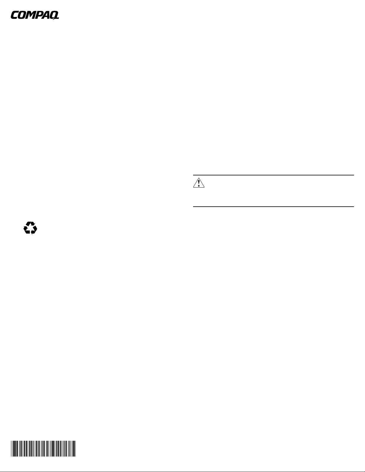
Kit Contents
■ Door lock control unit
- Mounting brackets (257661-001)
■ Country-specific power cord
■ Front rack door
- Lock assembly
- 91XX, 9842, and 106XX (257662-001)
- Latch assembly
- 91XX and 106XX (257662-002)
- 9842 (257662-003)
■ Rear rack door
- Lock assembly
- 91XX, 9842, and 106XX (257663-001)
- Latch assembly
- 91XX and 9842 (257663-002)
- 106XX (257663-003)
- Brackets
- Standard rack (257664-001)
- Standard rack with extension kit (257664-002)
■ Tie wraps
■ Cables
- Concealed Door Release cable assembly (257658-001)
- CMC lock command cable (231915-001)
-I2C communication cable (231526-002)
■ Software
- Compaq Intelligent Rack Manager Lite CD
- Power Products Documentation CD
■ Mounting hardware
- Screws
- Cage nuts
240828- 022
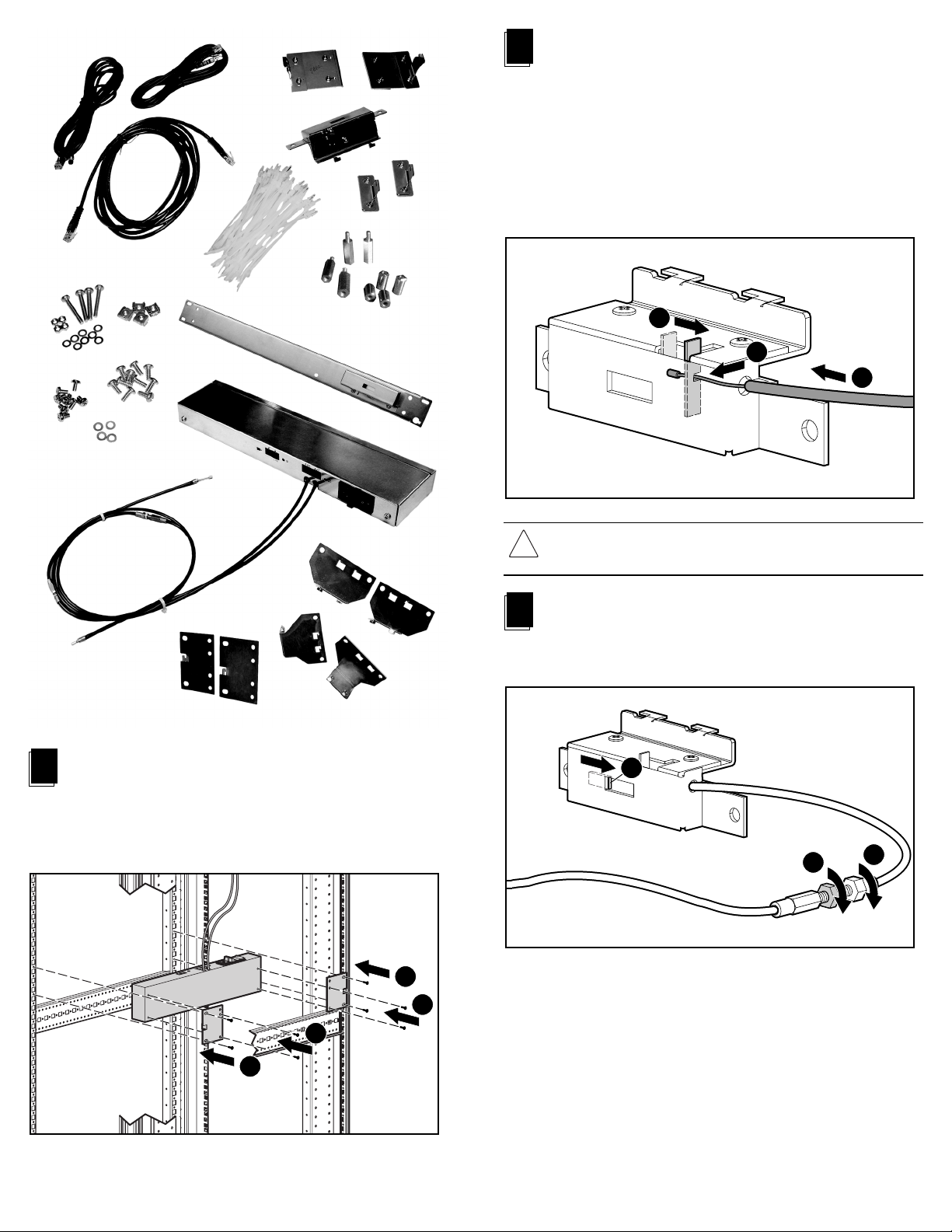
Connecting the Actuator Cable to the Lock
2
Mechanism
The actuator cables are attached to the door lock control unit. Use the short
cable to connect to the front lock mechanism and the longer cable to
connect to the rear lock mechanism.
To connect to the front lock mechanism, feed the actuator cable 2 through
the gap between the rack rail and frame. Slide the lever 1 and place the
actuator cable 2 into the opening, making sure to secure the end of the
cable 3 over the slot.
Repeat procedure to connect to the rear lock mechanism.
1
3
2
1
Installing the Door Lock Control Unit
Position the control unit between a front and rear rail. Attach the brackets to
the door lock control unit, using the M3 screws 1 Attach the brackets to
the rails using self-tapping screws 2. The control unit can face up or down
depending on specific installation requirements.
2
CAUTION: The actuator cable should be installed with a bend radius of at
least 100 mm to avoid kinking the cable. Do not bend or squeeze the
actuator cable.
3
Adjusting the Lock Mechanism
Turn the adjusting connector 1 until the edge of the latch 2 on the lock
mechanism moves above the edge of the opening. Secure with the locknut 3.
2
3
1
1
1
2
Continued on reverse

4
Installing the Front Door Lock Mechanism
Connect the front door lock assembly to the side of the front frame.
5
Installing the Front Door Lock Latch
91XX Series Rack with Extension Kit
Align the extension brackets (257664-002) on the rear door lock
mechanism and secure with the screws. Position the rear door lock
assembly as shown, so that the assembly extends towards the rear door.
Insert the self-tapping plate screws 2 to secure the rear door lock
mechanism 1 to the rack.
1
2
2
Align the latch with the lock mechanism. Insert the screws with the
backing plate 1 through the holes in the front door of the rack. On the
inside of the door, place the front door lock latch 2 over the screws and
secure with the hardware provided with this assembly 3. For 91XX and
106XX series racks, use latch assembly 257662-002. For the 9842 series
rack, use latch assembly 257662-003.
1
2
Installing the Rear Door Lock Mechanism
6
3
91XX Series Rack
Align the standard brackets (257664-001) on the rear door lock assembly
and secure with the screws. Position the rear door lock assembly as shown.
Insert the self-tapping screws 2 to secure the rear door lock mechanism
1 to the rack.
9842 Series Rack
Attach long spacers 1 to the rear rails using the cage nuts. Insert screws 4
and washers 3 to secure the door lock assembly 2 to the long spacers 1.
1
3
2
4
3
4
1
9842 Series Rack - Front and Rear Doors Reversed
Insert the screws 1 to secure the short spacers 2 and the rear door lock
assembly 3 to the front rails as shown, using screws, washers and nuts 4.
4
2
3
2
1
1
2
2
1
4

10000 Series Rack
To accommodate the double doors of a 106XX rack, unbolt the locking
mechanism from the crossbar and reposition in the left hole pair as shown
1. (For the 9000 series rack, use the right hole pair.)
Align the standard brackets (257664-001) on the rear door lock assembly
and secure with the screws. Position the rear door lock assembly as shown.
Insert the self-tapping screws 3 to secure the rear door lock mechanism
2 to the rack.
Set the address switch to 1 or 2 on the door lock control unit to match the
lock port that is connected to the CMC.
2
3
3
7
Installing the Rear Door Lock Latch
Align the latch with the lock mechanism. For 91XX and 9842 series
racks, use latch assembly (257663-002). For 106XX series racks, use latch
assembly 257663-003. Insert the screws with the backing plate 1 through
the holes in the rear door of the rack. On the inside of the door, place the
rear door lock latch 2 over the screws, securing with the hardware
provided in this assembly 3.
1
2
3
1
Connecting the Concealed Door
9
Release Cable
The concealed door release button 2 is designed to release the door locks
manually if this feature is activated in the Compaq Intelligent Rack
Manager Lite software. Connect the concealed door release cable
assembly 1 to the door lock control unit unlock port. Route the cable
through the rack and locate the push button 2 in a concealed location.
(This is a suggested location.)
2
1
8
Connecting to the CMC
Power off the CMC, then connect the I2C cable from the CMC to one of the
2
C ports on the door lock control unit 1. Connect the cable from the CMC
I
lock port 1 or 2, to the lock port on the door lock control unit. The cables can
be routed through the rack and then attached by using tie wraps.
1
10
Connecting the Power Cord
Connect the country-specific power cord to the socket on the door
lock control unit.
Continued on next page

11
Connecting to an Additional Rack
A single CMC can support up to two door lock kits. Repeat steps
1 through 7 to complete installation of the door lock equipment for the
second rack. Connect the second I
control units. Connect the cable from the lock port to the open CMC lock
port 1. Set the switch on the door lock control unit to match the lock port
used on the CMC. Connect the second concealed door release cable and
the AC power cable as detailed in steps 9 and 10.
2
For translated documents, refer to the PPD CD included with the option kit.
2
C cable 2 between the two door lock
1
Configuring the Software
12
Configure the door lock control unit using the Compaq Intelligent
Rack Manager Lite software (see the Compaq Console Manage-
ment Controller User Guide). One CMC is able to support up to
two door lock kits.
DOORS AND SENSORS:
For each door lock kit, select the doors that must be closed before
the lock should activate. Intrusion sensors must monitor these
selected doors. From the Accessory Setup screen of the Compaq
Intelligent Rack Manager Lite software, select at least one door
for each lock kit.
Each door lock control unit locks and unlocks, as a pair, the front
door and the rear door of a single rack. For a secure rack, the
system should verify that the front and rear doors are closed
before the lock activates. The intrusion sensors indicate to the
system that the doors are closed and are ready to be locked.
PRESETS:
From the Accessory Setup screen, preset the lock response to
four fault conditions:
■ Power Failure
■ Low Battery
■ Network Failure
■ Communication Failure
Hardware installation is complete.
LED Configuration
The door lock control unit has the following LEDs.
1 Power LED
■ Green - On
2 I2C Communication LED/Status LED
■ Green flashing - Communication Traffic
■ Red flashing - System Error or Battery Charging
2
1
If any of these faults occur, the door lock control unit responds by
keeping the doors locked, or by immediately unlocking the doors,
or by enabling the Concealed Door Release button, as selected in
the software.
SETUP EXAMPLE:
Power Failure No
Low Battery Yes
Network Failure Enable Concealed Door Release
Communication Failure Enable Concealed Door Release
The rack remains locked if the door lock control unit loses AC
power. The door lock control unit continues to operate using the
backup battery power.
NOTE: If the CMC also loses AC power, you will not be able to change any settings.
If the AC power is not restored within approximately six hours,
the Low Battery alert is triggered and the doors unlock. This alert
ensures that sufficient battery power is reserved to unlock the
doors. After 30 minutes, the door lock control unit stops functioning. When the AC power is restored, the door lock control unit
automatically relocks all the doors and begins recharging the
batteries.
If the CMC detects a network failure, the doors can be opened by
pressing the Concealed Door Release button. The CMC determines a Network Failure has occurred if the CMC fails to
communicate with the Compaq Intelligent Rack Manager Lite
software for approximately four minutes.
NOTE: If you are using management software other than Compaq Intelligent Rack
Manager Lite, ensure that the Network Failure condition is selected as No.
If the Compaq Intelligent Rack Manager Lite service is not running on the
management console, the CMC detects a Network Failure and responds
accordingly.
If the CMC loses communication with the door lock control unit,
a communication failure will be triggered. The doors can then be
opened by pressing the Concealed Door Release button.

Maintenance
WARNING: To reduce the risk of injury from electric shock, remove the power
cord before servicing.
When the CMC indicates that the batteries in the door lock control unit
require changing, remove the screws 1, lift the cover 2 off, and replace
the six batteries with the same type and capacity (NiMH, size AA,
1100mAh) 3.
CAUTION: There is a risk of explosion if battery is replaced by an incorrect type.
Dispose of used batteries properly.
2
1
1
3
If the fuse 2 has opened, be sure that the condition that caused the fault
has been cleared. Remove the fuse cover 1. Replace the fuse 2 with the
exact rating as specified on the unit label. The second fuse 3 is a spare.
Contact your Compaq authorized service representative for more details.
1
3
2
Repairs to the CMC door lock control unit and lock mechanism must be
carried out by Compaq or a Compaq authorized service representative.
 Loading...