

Page 1
United States January 3, 2003
Presario 1600 Series
Models: 1683, 1685, 1687, 1688, 1690, 1692, 1693, and 1694
Before You Begin Specifications Parts Catalog
Removal Sequence Troubleshooting Battery Operations
Product Description Pin Assignments
Index
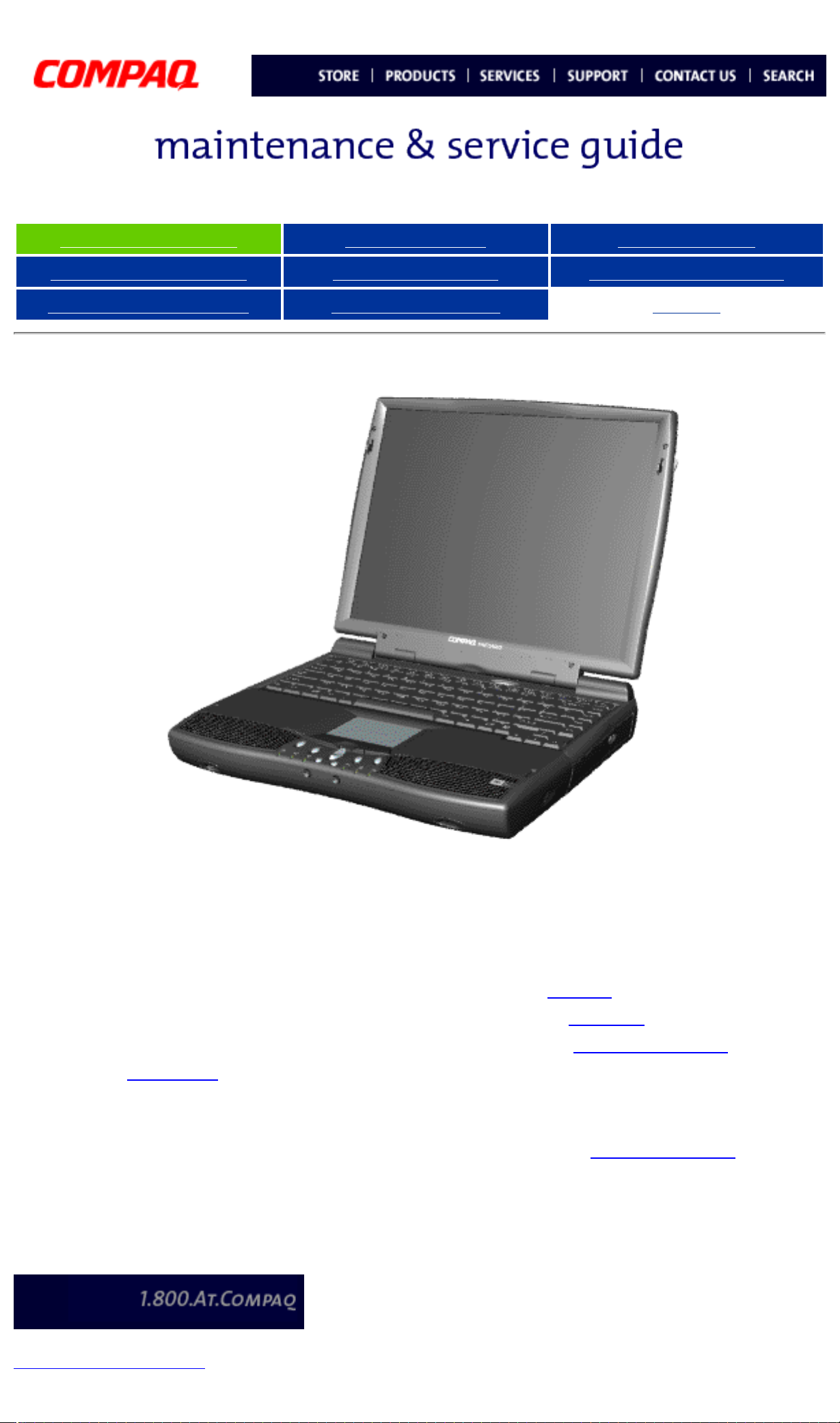
Compaq Presario 1600 System
Welcome to the Maintenance & Service Guide (MSG). This
online guide is designed to serve the needs of those whose
job it is to repair Compaq products. The Notice, contains the
copyright and trademark information. The
symbol conventions, Technician Notes and
Preface shows
Serial Number
locations on the unit. This MSG will be periodically
maintained and updated online as needed.
For content comments or questions, contact Tech Support.
To report a technical problem, contact your Regional Support
Center or IM Help Center.
privacy and legal statement
Page 2
United States January 3, 2003
Presario 1600 Series
Models: 1683, 1685, 1687, 1688, 1690, 1692, 1693, and 1694
Before You Begin Specifications Parts Catalog
Removal Sequence Troubleshooting Battery Operations
Product Description Pin Assignments
Index
Notice
The information in this guide is subject to change without notice.
COMPAQ COMPUTER CORPORATION SHALL NOT BE LIABLE FOR TECHNICAL
OR EDITORIAL ERRORS OR OMISSIONS CONTAINED HEREIN, NOR FOR
INCIDENTAL OR CONSEQUENTIAL DAMAGES RESULTING FROM THE
FURNISHING, PERFORMANCE, OR USE OF THIS MATERIAL.
This guide contains information protected by copyright. No part of this guide may be
photocopied or reproduced in any form without prior written consent from Compaq
Computer Corporation.
1998 Compaq Computer Corporation.
All rights reserved. Printed in the U.S.A.
Compaq, Presario Series Registered U. S. Patent and Trademark Office.
Microsoft, MS-DOS, and Windows are registered trademarks of Microsoft Corporation.
Windows 98 is a trademark of Microsoft Corporation.
The software described in this guide is furnished under a license agreement or
nondisclosure agreement. The software may be used or copied only in accordance with
the terms of the agreement.
Product names mentioned herein may be trademarks and/or registered trademarks of
their respective companies.
Maintenance and Service Guide
Compaq Presario Series Portable Computer
First Edition (March 1999)
Compaq Computer Corporation
Page 3
United States January 3, 2003
Presario 1600 Series
Models: 1683, 1685, 1687, 1688, 1690, 1692, 1693, and 1694
Before You Begin Specifications Parts Catalog
Removal Sequence Troubleshooting Battery Operations
Product Description Pin Assignments
Index
Preface
This Maintenance and Service Guide is a troubleshooting guide that can be used for reference when
servicing the Compaq Presario Series Portable Computers.
Compaq Computer Corporation reserves the right to make changes to the Compaq Presario Series
Portable Computers without notice.
Symbols
The following words and symbols mark special messages throughout this guide.
WARNING: Text set off in this manner indicates that failure to follow directions in the
warning could result in bodily harm or loss of life.
IMPORTANT:
NOTE:
Text set off in this manner presents commentary, sidelights, or interesting points of
information.
CAUTION: Text set off in this manner indicates that failure to follow directions could
result in damage to equipment or loss of data.
Text set off in this manner presents clarifying information or specific instructions.
Technician Notes
WARNING: Only authorized technicians trained by Compaq should repair this
equipment. All troubleshooting and repair procedures are detailed to allow only
subassembly/module level repair. Because of the complexity of the individual boards
and subassemblies, the user should not attempt to make repairs at the component
level or to make modifications to any printed circuit board. Improper repairs can create
a safety hazard. Any indications of component replacement or printed circuit board
modifications may void any warranty
Serial Number
When requesting information or ordering spare parts, the computer serial number should be
provided to Compaq. The serial number is located on the bottom of the computer.
Locating Additional Information
.
The following documentation is available to support this product:
● Compaq Presario Series Portable Computer documentation set
● Introducing Windows 98 Guide
● Service Training Guides
● Compaq Service Advisories and Bulletins
● Compaq QuickFind
● Compaq Service Quick Reference Guide
privacy and legal statement
Page 4

United States January 3, 2003
Presario 1600 Series
Models: 1683, 1685, 1687, 1688, 1690, 1692, 1693, and 1694
Before You Begin Specifications Parts Catalog
Removal Sequence Troubleshooting Battery Operations
Product Description Pin Assignments
Index
Specifications
This chapter covers the following specifications of Compaq Presario Series Portable Computers:
● Physical and Environmental
● System Interrupts
● System DMA
● System I/O Address
● System Memory Catalog
● Display
● Memory Expansion
● Diskette Drive
● Hard Drive
● DVD or CD Drive
● Battery Pack
Physical and Environmental
Computer Specifications
Dimensions
Height
Depth
Width
Weight
Model 1683
Model 1685
Model 1687
Model 1688
Model 1690
Stand-Alone (Battery Pack)
U.S. Metric
1.97 in
12.32 in
10.12 in
(Data not
available)
7.19lbs
7.19 lbs
7.36 lbs
7.76 lbs
5.0 cm
31.3 cm
25.7 cm
(Data not available)
3260 g
3260 g
3340 g
3520 g
Li Ion
Power Requirements
Nominal Operating Voltage
Maximum Operating Power
W @ 14.8 VDC
W @ 56.5 W
W @ 58.5 W
Peak Operating Power
AC Power Requirements
Operating Voltage
Operating Current
Operating Frequency
Maximum Transient
Temperature
Operating 41° to 95 °F 5° to 35 °C
Nonoperating -4° to 140 °F -20° to 60 °C
Relative Humidity (Non-condensing)
Operating 10 to 90% 35°C to 90%
Nonoperating (tw = 38.7°C max) 5 to 95% 60°C to 95%
Altitude
(Information not available)
Operating 0 to 10,000 ft 0 to 3.15 km
Nonoperating 0 to 30,000 ft 0 to 10.14 km
Shock
Operating 10 G, 11 ms, half
Non operating 240 G, 2 ms, half
Vibration
Operating 0.55 G, 0.25
Nonoperating 1.5 G, 0.25 Oct/Min
Applicable product safety standards specify thermal limits for plastic surfaces.
NOTE:
Compaq Presario Series Portable Computers operate well within this range of
temperatures.
sine
sine
Oct/Min sweep rate
sweep rate
System Interrupts
Hardware IRQ System Function
IRQ0
IRQ1
IRQ2
IRQ3 IRQ Holder for PCI Steering
IRQ3 ALi PCI to USB Open Host Controller
IRQ4
IRQ5 IRQ Holder for PCI Steering
System Timer
Standard 101/102-Key or Microsoft Natural Keyboard
Programmable interrupt controller
Communications Port (COM1)
System Interrupts
IRQ5 ESS SOLO-1 PCI AudioDrive
IRQ5 IRQ Holder for PCI Steering
IRQ6 Standard Floppy Disk Controller
IRQ7 Printer Port (LPT1)
IRQ8 System CMOS / real-time clock
IRQ9 RAGE LT PRO AGP 2X (English)
IRQ9 IRQ Holder for PCI Steering
IRQ10 Texas Instruments PCI-1211 CardBus Controller
IRQ10 IRQ Holder for PCI Steering
IRQ10
IRQ12 Synaptics PS/2 TouchPad
IRQ13 Numeric data processor
IRQ14
Lucent 56K V.90 PCI DF Modem
ALi M5229 PCI Bus Master IDE Controller
IRQ14 Primary IDE controller (dual fifo)
IRQ15
IRQ15 Secondary IDE controller (dual fifo)
System DMA
Hardware DMA System Function
0
1 ESS SOLO-1 DOS Emulation
2 Standard Floppy Disk Controller
3 (free)
ALi M5229 PCI Bus Master IDE Controller
System DMA
(free)
4 Direct memory access controller
5 (free)
System I/O Address
I/O Address (Hex) System Function (Shipping Configuration)
0000 - 000Fh Direct Memory Access Controller
0020h - 0021h Programmable Interrupt Controller
0040h - 0043h System Timer
0060h - x0060h Standard 101/102-Key or Microsoft Natural Keyboard
0061h - x0061h System Speaker
0064h - x0064h Standard 101/102-Key or Microsoft Natural Keyboard
System I/O Address
0070h - 0071h System CMOS/Real Time Clock
0080h - 0080h Motherboard Resources
0081h - 008Fh Direct Memory Access controller
0092h - 0092h Motherboard Resources
00A0h - 00A1h Programmable Interrupt Controller
00B1h - 00B3h Motherboard Resources
00C0h - 00DFh Direct Memory Access controller
00EAh - 00EBh Motherboard Resources
00F0h - 00FFh Numeric Data Processor
0100h - 010Fh Motherboard Resources
0170h - 0177h
0170h - 0177h Secondary IDE Controller (dual fifo)
ALi M5229 PCI Bus Master IDE Controller
01F0h - 01F7h ALi M5229 PCI Bus Master IDE Controller
0200h - 0203h Gameport Joystick
0220h - 022Fh ESS SOLO-1 DOS Emulation
0330h - 0331h ESS SOLO-1 DOS Emulation
0376h - 0376h Secondary IDE Controller (dual fifo)
0376h - 0376h ALi M5229 PCI Bus Master IDE Controller
0378h - 037Fh Printer Port (Ltp1)
0388h - 038Bh ESS SOLO-1 DOS Emulation
03B0h - 03BBh RAGE LT PRO AGP 2X (English)
03C0h - 03DFh RAGE LT PRO AGP 2X (English)
03F0h - 03F5h Standard Floppy Disk Controller
03F6h - 03F6h Primary IDE Controller (dual fifo)
03F6h - 03F6h ALi M5229 PCI Bus Master IDE Controller
03F7h - 03Fh7 Standard Floppy Disk Controller
03F8h - 03FFh Communication Port (COM1)
040Bh - 040Bh Motherboard Resources
040D0h - 04D1h Motherboard Resources
04D6h - 04D6h Motherboard Resources
0CF8h - 0CFFh PCI Bus
1000h - 103Fh Motherboard Resources
1040h - 105Fh Motherboard Resources
1060h - 106Fh ESS SOLO-1 PCI AudioDrive
1070h - 107Fh ESS SOLO-1 PCI AudioDrive
1400h - 14FFh Lucent 56K V.90 PCI DF Modem
1800h - 183Fh ESS SOLO-1 PCI AudioDrive
1840h - 1847h
1840h - 184Fh
1848h - 184Fh
Primary IDE Controller (dual fifo)
ALi M5229 PCI Bus Master IDE Controller
Secondary IDE Controller (dual fifo)
1850h - 1853h ESS SOLO-1 PCI AudioDrive
1854h - 1857h ESS SOLO-1 PCI AudioDrive
1858h - 185Fh Lucent 56K V.90 PCI DF Modem
2000h - 2FFFh PCI Standard PCI-to-PCI Bridge
2000h - 20FFh
System Memory Catalog
Memory Address System Function
00000000h - 0009FFFFh System Board Extension for PnP BIOS
000A0000h - 000AFFFFh RAGE LT PRO AGP 2X (English)
000B0000h - 000BFFFFh RAGE LT PRO AGP 2X (English)
RAGE LT PRO AGP 2X (English)
System Memory Catalog
000C0000h - 000CBFFFh RAGE LT PRO AGP 2X (English)
000DC000h - 000DFFFFh
000E0000h - 000FFFFFh System Board Extension for PnP BIOS
00100000h - 01FFFFFFh System Board Extension for PnP BIOS
0C000000h - 0C000FFFh Texas Instruments PCI-1211 CardBus Controller
E0000000h - E3FFFFFFh ALi M1541 AGP System Controller
FC000000h - FCFFFFFFh ALi PCI to USB Open Host Controller
FC001000h - FC0010FFh
FC100000h - FDFFFFFFh
FC100000h - FC100FFFh RAGE LT PRO AGP 2X (English)
FC120000h - FC13FFFFh RAGE LT PRO AGP 2X (English)
Motherboard Resources
Lucent 56K V.90 PCI DF Modem
PCI Standard PCI-to-PCI bridge
FD000000h - FDFFFFFFh RAGE LT PRO AGP 2X (English)
FFFC0000h - FFFFFFFFh Motherboard Resources
Display
Dimensions
Height
Width
Diagonal Size
Mounting
Number of Colors
12.1" (Diagonal) TFT Display with LVDS
U.S. Metric
7.83"
10.8"
12.1" 30.7 cm
Internal
16 M
19.9 cm
25.7 cm
Contrast Ratio
Brightness
Pixel Resolution
Pitch
Format
Configuration
Backlight
Character Display
Total Power Consumption
(Information not available)
13.3" (Diagonal) TFT Display with LVDS
Typical 150:1
Over 120 cd/m~3
0.30 x 0.30 mm
800 x 600
RGB Stripe
Edge Light
80 x 25, 80 x 50
5.4 W (max)
U.S. Metric
Dimensions
Height
Width
Diagonal Size
Mounting
Number of Colors
Contrast Ratio
Brightness
Pixel Resolution
Pitch
Format
Configuration
Backlight
Character Display
Total Power Consumption
14.1" (Diagonal) TFT Display with LVDS
Dimensions
Height
Width
Diagonal Size 14.1" 35.8 cm
Mounting Internal
Number of Colors 64 K
Contrast Ratio Typical 150:1
Brightness Over 120 cd/m~3
Pixel Resolution
Pitch
Format
Configuration
U.S. Metric
8.43"
11.2"
0.279 x 0.279 mm
1024 x 768
RGB Stripe
21.42 cm
28.56 cm
Backlight
Character Display
Total Power Consumption 6.6 W (max)
Memory Expansion
Base System Memory Expansion Board Memory Total Memory
32-MB
32-MB
32-MB
64-MB
64-MB
Edge Light
80 x 25
32-MB 64-MB
64-MB 96-MB
128-MB 160-MB
32-MB 96-MB
64-MB 128-MB
Diskette Drive
Diskette Size
Light
Height
Bytes per Sector:
Sectors per Track
High Density
Low Density
Tracks per Side
High Density
Low Density
64-MB
128-MB 192-MB
Diskette Drive
3.5 in
None
.5" / 1.27 cm
512
18 (1.44-MB) / 15 (1.2-MB)
9
80 (1.44-MB) / 80 (1.2-MB)
80
Access Times
Track-to-Track (high/low)
Average (ms)
Setting Time (ms)
Latency Average
Number of Read/Write Heads
Hard Drive
Capacity Per Drive
Drive Type
3 ms/6 ms
94 ms/174 ms
15 ms
100
2
Hard Drives
6.4-GB 4.8-GB
Not Available
6.4-GB 4.8-GB
65 65
Physical Configuration
Cylinders
Heads
Sectors per track
Bytes per sector
Logical Configuration
Cylinders
Heads
Sectors per track
Bytes per sector
Seek Times
(Typical, Including settling in ms)
Track to Track
Average Maximum
Rotational Speed
Transfer Rate
Media
At interface
Sector Interleave
8647
6
240-250
512
13424
15
63
512
2.5 ms
13 ms
23 ms
4200 rpm
60.8 to 107.2 Mb/s
33.3 MB/s
1:1 1:1
8647
6
240-250
512
7944
15
63
512
2.5 ms
13 ms (read)
23 ms
4200 rpm
60.8 to 107.2 Mb/s
33.3 MB/s
Buffer Size
DVD or CD Drive
Applicable Disk
Center Hole Diameter
Disc Diameter
Disc Thickness
Track Pitch
512 KB 512 KB
CD Drive
24x CD Drive
CD-DA, CD-ROM, CD-ROM XA, CD-1, Photo CD
(multisession), Video CD, CD-R, CD-Extra (CD+),
CD-G, CD-RW
.6" / 15 mm
12 cm, 8 cm
1.2 mm
1.6 um
Access Time
(typical, including setting)
Audio Output Level
Line out
Headphone
Cache Buffer
Data Transfer Rate
(typical, including setting)
110 ms
+/- 0.27 Vrms
none
128 KB
3600 KB/s
150 KB/s
16.66 MB/sec
Startup Time
Stop time
< 8 sec
< 4 sec
DVD Drive
Applicable Disk
Center Hole Diameter
Access Time
(typical, including setting)
Disc Thickness
Track Pitch
Laser
Beam Divergence
Audio Output Level
Line out
Headphone
Cache Buffer
Data Transfer Rate
(typical, including setting)
DVD-ROM, CD-ROM, CD-XA, CD-I, Photo CD,
Multisession, Audio, CD-R, CD-RW
6" / 15mm
< 100 ms (CD)
< 150 ms (DVD)
4.7", 3.15" / 12cm, 8cm
0.74um (DVD)
.05" / 1.2cm
1.0 volts RMS
0 - 0.6 volts RMS
512 KB/s (CD)
12,000 - 3,000 KB/s (CD)
2705 KB/s (DVD)
Startup Time
Stop time
Battery Pack
Dimensions
Height
Length
Width
Weight
< 5 sec
< 3 sec
Battery Pack
Lithium Ion (Li ion) *
US Metric
.81 in
3.05 in
5.69 in
0.85 Ib
2.05 cm
7.75 cm
14.45 cm
.39 kg
Battery Pack Operating Time
Energy
Voltage
Amp-hour capacity
Watt-hour capacity
Environmental Requirements
Operating Temperature
Non-operating Temperature
2 to 3 hours
14.8 V
3.0 Ah
44.4 Wh
32° F to 113 F
-4° F to 140 ° F
0° to 45° C
-20° to 60° C
Modem
Compliance
Data
Compression
ITU v.90~6 standard
Full ITU-T V.34 compliance
Full compliance with: V.21, V.22, V.22bis, V.23, V.32, V.32bis, Bell
103, Bell 212A
V.42bis/MNP 5
Fax Modulation
Command Set
Cable
Top of Page
privacy and legal statement
V. 17
V. 21 (Group III Compatible)
V.29
V.27Ter
Hayes AT
Class 1 Fax
6 Ft. RJ-11 telephone cable
Page 5
United States January 3, 2003
Presario 1600 Series
Models: 1683, 1685, 1687, 1688, 1690, 1692, 1693, and 1694
Before You Begin Specifications Parts Catalog
Removal Sequence Troubleshooting Battery Operations
Product Description Pin Assignments
Parts Catalog
System Unit
System Boards
Display
Assembly
Mass Storage
Devices
Miscellaneous
Cable Kit
Miscellaneous
For the Compaq Presario 1600 Series of Portable Computers listed above,
this section of the Maintenance and Service Guide provides the following
information:
● An illustrated breakdown of components
● Identification of spare parts and the ordering number associated
with each item(s)
Click on the appropriate categories listed to the left.
Index
Hardware Kit
Miscellaneous
Plastics Kit
Miscellaneous
Parts
Documentation
and Software
privacy and legal statement
Page 6
United States January 3, 2003
Presario 1600 Series
Models: 1683, 1685, 1687, 1688, 1690, 1692, 1693, and 1694
Before You Begin Specifications Parts Catalog
Removal Sequence Troubleshooting Battery Operations
Product Description Pin Assignments
Removal and Replacement
Removal
Sequence
Cables and
Connectors
Battery Pack
Palmrest
Cover with
Touch Pad
Heatspreader
Keyboard
Introduction
Prior to conducting any removal and/or replacement
IMPORTANT:
Note:
procedures, you should review and fully understand the
section titled "
The Internal Ethernet Card is Not Available for computer
models: 1683, 1685, 1687, 1688, 1690, 1692, 1693, and
1694. The Ethernet Plug was removed on later models.
Before You Begin".
Index
Processor
Hard Drive
DVD or
CD Drive
Battery
Charger
Board
Modem
Display Panel
Assembly
Upper CPU
Cover
Network
Interface
Card
Speaker
Assembly
Diskette
Drive
Fan Assembly
System Board
Dip Switch
Settings
Memory
Module
privacy and legal statement
Page 7
United States January 3, 2003
Presario 1600 Series
Models: 1683, 1685, 1687, 1688, 1690, 1692, 1693, and 1694
Before You Begin Specifications Parts Catalog
Removal Sequence Troubleshooting Battery Operations
Product Description Pin Assignments
Preliminary
Steps
Clearing the
Power-On
Password
Power-On
Self Test
(POST)
Compaq
Diagnostics
Diagnostic
Error Codes
Solving
Minor
Problems
Contacting
Compaq
Support
Introduction
This section covers troubleshooting information for the above
listed Compaq Presario 1600 Series Portable Computers. The
basic steps in troubleshooting include:
1. Follow the Preliminary Steps.
2. Run the Power-On Self-Test (POST).
3. Follow the recommended actions described in the
diagnostic tables, if you are unable to run POST or if
POST displays an error message.
When following the recommended actions in the Sections on
POST and Diagnostic Error Codes perform them in the order
listed. Rerun POST after each recommended action until the
problem is solved and no error message occurs. Once the
problem is solved, do not complete the remaining
recommended actions.
Index
NOTE:
privacy and legal statement
If the problem is intermittent, check the computer
several times to verify that the problem is solved
Page 8
United States January 3, 2003
Presario 1600 Series
Models: 1683, 1685, 1687, 1688, 1690, 1692, 1693, and 1694
Before You Begin Specifications Parts Catalog
Removal Sequence Troubleshooting Battery Operations
Product Description Pin Assignments
Index
Battery Pack Operating Time
This appendix covers the following information concerning battery pack operating time:
● Increase battery pack operating time
● Conditioning a battery pack
● Disposal of a used battery pack
Increasing Battery Pack Operating Time
Battery pack operating time differs depending on several variables. To avoid unnecessary
replacement, consider the following variables when determining how long a charged battery pack
should last:
● Power management settings
● Hardware configuration
● Software applications
● Installed options
● Display brightness
● Hard drive usage
● Changes in operating temperature
● Type and number of installed PC Cards
The power consumption requirements for PC
NOTE:
Cards vary widely. Some cards drain the battery
pack very rapidly.
Minimizing the Energy Required
Battery pack operating time can be increased by as much as 50 percent by controlling the energy
required by the computer and the energy stored in the battery pack.
To minimize the energy required by the computer, follow these steps:
● Set the power conservation levels in the Power Management utility to
Maximum.
● Customize the timeout value to work more efficiently with the applications.
The amount of battery life depends on the values selected.
Maximizing the Energy Stored
To maximize the energy stored in the battery pack, follow these guidelines:
● Condition the battery pack at least every 30 days to improve overall battery
performance.
● Keep a battery pack in the computer when using it with AC power to supply
the battery pack with a constant trickle charge.
● Store the battery pack in a cool, dry place when not in use.
Conditioning a Battery Pack
CAUTION: To avoid a loss of data, ensure that all data is saved before
discharging a battery pack.
To condition a battery pack, complete the following steps:
1. Plug in the AC adapter and allow the battery to charge until the LED light on
the display stops blinking. Your battery gauge may read 100 percent for a
period of time before LED light on the display stops blinking. Do not unplug
the AC adapter until the arrow disappears.
2. Unplug the AC adapter and allow the battery to drain until the computer
reaches hibernation and turns itself off. Do not plug in the AC adapter
during this process or you will need to restart with Step No. 1. You
may use the computer while the battery is draining.
3. Your battery is re-conditioned.
4. Plug in the AC adapter and begin using the computer.
The table below shows the approximate battery pack charge times.
Approximate Battery Charge Time
Computer On Line Off Line
NiMH Battery Pack 4.0 hours premature termination 2:00 hrs
Li ion Battery Pack 4.5 hours premature termination 2:50 hrs
Disposal of a Used Battery Pack
In the interest of safeguarding our environment. Compaq Computer Corporation recommends
that nickel metal hydride (NiMH) and lithium ion (Li ion) battery packs be recycled. Battery packs
should be handled in accordance with country, state, province, or local regulations.
CAUTION: Never attempt to open or service a battery pack. Opening a battery
pack not only damages the pack and makes it unusable, but also expose
potentially harmful battery components.
Top of Page
privacy and legal statement
Page 9
United States January 3, 2003
Presario 1600 Series
Models: 1683, 1685, 1687, 1688, 1690, 1692, 1693, and 1694
Before You Begin Specifications Parts Catalog
Removal Sequence Troubleshooting Battery Operations
Product Description Pin Assignments
Product Description
Models and
Features
Controls and
Lights
Front Bezel
Lights
Front Bezel
Buttons
Left Side
Components
Right Side
Components
Underside of
Unit
Rear Connectors
Power
Management for
Windows 98
Index
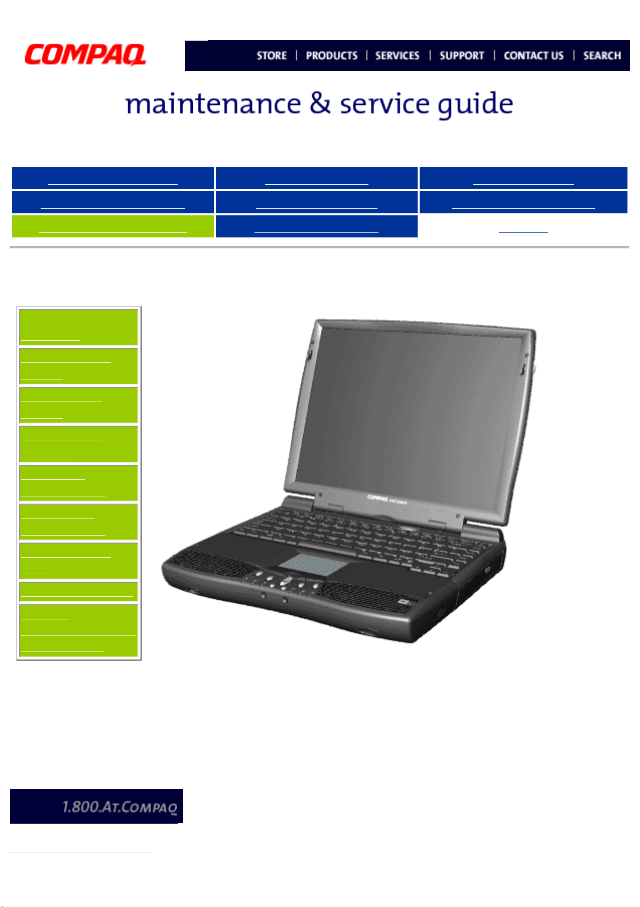
The
Compaq
Presario
1600 Series
Computers,
the new
generation
of
multimedia
portables,
present an
innovative
and
integrated
design,
outstanding
audio and
video,
advanced
core
features,
and
attractive
styles. This
fully
functional
AMD-K6based
portable
computer
allows full
desktop
versatility.
privacy and legal statement
Page 10
United States January 3, 2003
Presario 1600 Series
Models: 1683, 1685, 1687, 1688, 1690, 1692, 1693, and 1694
Before You Begin Specifications Parts Catalog
Removal Sequence Troubleshooting Battery Operations
Product Description Pin Assignments
Index
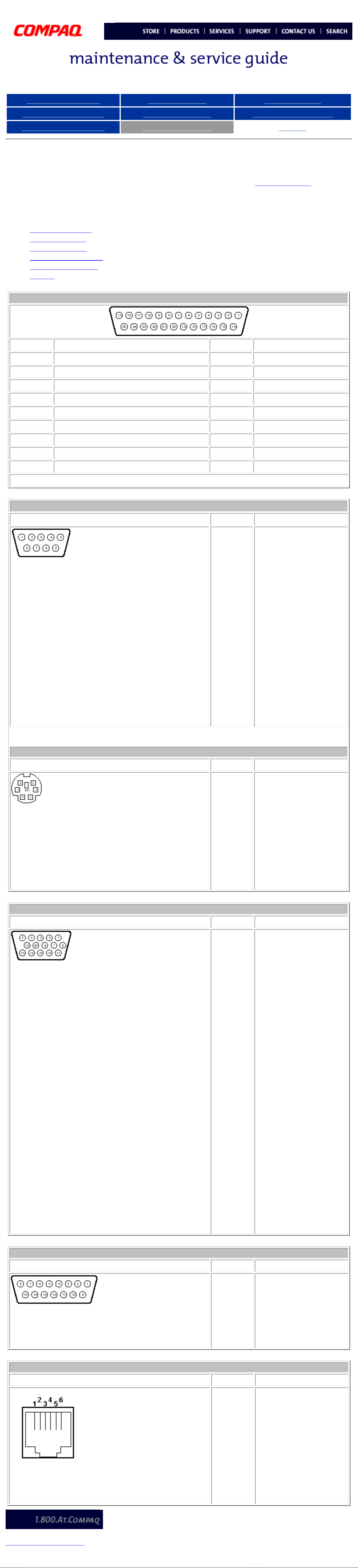
Connector Pin Assignments
This appendix provides connector pin assignment tables for Compaq Presario Series Portable
Computers. For more information on connectors, refer to the section on Rear Connectors.
NOTE: The signals in all tables of this appendix are considered "active high" unless otherwise
indicated by an asterisk (*).
● Parallel Connector
● Serial Connector
● Keyboard/Mouse
● External VGA Monitor
● Universal Serial Bus
● Modem
Parallel Connector
Pin Signal Pin Signal
1 Strobe* 10 Acknowledge*
2 Data Bit 0 11 Busy
3 Data Bit 1 12 Paper Out
4 Data Bit 2 13 Select
5 Data Bit 3 14 Auto Linefeed*
6 Data Bit 4 15 Error*
7 Data Bit 5 16 Initialize Printer*
8 Data Bit 6 17 Select In*
9 Data Bit 7 18-25 Signal Ground
* = Active low
Serial Connector
Connector Pin Signal
1
2
3
4
5
Carrier Detect
Receive Data
Transmit Data
Data Terminal Ready
Signal Ground
6
7
8
9
Data Set Ready
Ready to Send
Clear to Send
Ring Indicator
Keyboard/Mouse
Connector Pin Signal
1
2
Data 1
Data 2
3
4
5
6
External VGA Monitor
Ground
+5 V
Clock 1
Clock 2
Connector Pin Signal
1
2
3
Red Analog
Green Analog
Blue Analog
4
5
6
7
8
9
10
11
Not connected
Ground
Ground Analog
Ground Analog
Ground Analog
Not connected
Ground
Monitor Detect
12
13
14
15
Universal Serial Bus
DDC2B Data
Horizontal Sync
Vertical Sync
DDC2B Clock
Connector Pin Signal
1
+5V
Data -
2
Data +
3
Ground
4
Modem
Connector Pin Signal
1
2
3
4
5
6
Unused
Unused
Tip
Ring
Unused
Unused
privacy and legal statement
Page 11
United States January 3, 2003
Presario 1600 Series
Models: 1683, 1685, 1687, 1688, 1690, 1692, 1693, and 1694
Before You Begin Specifications Parts Catalog
Removal Sequence Troubleshooting Battery Operations
Product Description Pin Assignments
Before You Begin
Electrostatic
Discharge
Service
Considerations
Preparation
for
Disassembly
Index
privacy and legal statement
Report the computer serial
number to Compaq when
requesting information or
ordering spare parts.
Page 12
United States January 3, 2003
Presario 1600 Series
Models: 1683, 1685, 1687, 1688, 1690, 1692, 1693, and 1694
Before You Begin Specifications Parts Catalog
Removal Sequence Troubleshooting Battery Operations
Product Description Pin Assignments
Before You Begin
Electrostatic
Discharge
Service
Considerations
Preparation
for
Disassembly
Electrostatic Discharge
A sudden discharge of static electricity from a finger or other
conductor can destroy static-sensitive devices or
microcircuitry. Often the spark is neither felt nor heard, but
damage occurs. An electronic device exposed to electrostatic
discharge (ESD) may not be affected at all and will work
perfectly throughout a normal cycle. Although, it may function
normally for a while, then degrade in the internal layers,
reducing its life expectancy.
Index
Networks built into many integrated circuits provide some
protection, but in many cases, the discharge contains enough
power to alter device parameters or melt silicon junctions.
Generating Static
The table shows how different activities generate static
electricity and at different electrostatic voltage levels.
Typical Electrostatic Voltages
Event 10% 40% 55%
Walking across carpet 35,000 V 15,000 V 7,500 V
Walking across vinyl floor 12,000 V 5,000 V 3,000 V
Relative Humidity
Motions of bench worker 6,000 V 800 V 400 V
Removing DIPS from plastic
2,000 V 700 V 400 V
tubes
Removing DIPS from vinyl
11,500 V 4,000 V 2,000 V
trays
Removing DIPS from
14,500 V 5,000 V 3,500 V
Styrofoam
Removing bubble pack from
26,000 V 20,000 V 7,000 V
PCBs
Packing PCBs in foam-lined
21,000 V 11,000 V 5,000 V
box
NOTE: 700 volts can degrade
a product.
privacy and legal statement
Page 13
United States January 3, 2003
Presario 1600 Series
Models: 1683, 1685, 1687, 1688, 1690, 1692, 1693, and 1694
Before You Begin Specifications Parts Catalog
Removal Sequence Troubleshooting Battery Operations
Product Description Pin Assignments
Before You Begin
Electrostatic
Discharge
Service
Considerations
Preparation
for
Disassembly
Service Considerations
Listed below are some of the considerations that you should keep in mind
during the disassembly and assembly of the computer.
Tool and Software Requirements
To service the computer, you need the following:
● Compaq screwdriver kit (Spare Part No. 161946-001)
● Torx T-9 screwdriver
● 3/16-inch and 5mm nut drivers (for screwlocks and
standoffs)
● Small, standard screwdriver
● Small, Phillips screwdriver
● Diagnostics software
Index
Screws
The screws used in the computer are not interchangeable. If an incorrect
screw is used during the reassembly process, it can damage the unit.
Compaq strongly recommends that all screws removed during disassembly be
kept with the part that was removed, then returned to their proper locations.
IMPORTANT:
privacy and legal statement
As each subassembly is removed from the computer, it
should be placed away from the work area to prevent
damage.
Page 14
United States January 3, 2003
Presario 1600 Series
Models: 1683, 1685, 1687, 1688, 1690, 1692, 1693, and 1694
Before You Begin Specifications Parts Catalog
Removal Sequence Troubleshooting Battery Operations
Product Description Pin Assignments
Before You Begin
Electrostatic
Discharge
Service
Considerations
Preparation
for
Disassembly
Preparing the Computer for Disassembly
1. Disconnect AC power and any external devices.
2. Remove the battery pack.
3. Remove any PC Cards.
IMPORTANT:
The battery pack should be removed before performing any
internal maintenance on the computer.
Index
NOTE:
WARNING: Metal objects can damage the battery pack as well as the
battery contacts in the battery compartment. To prevent damage, do
not allow metal objects to touch the battery contacts. Place only the
battery pack for the Compaq Presario Series Portable Computers into
the battery compartment. Do not force the battery pack into the bay
if insertion does not occur easily.
CAUTION: Do not crush, puncture, or incinerate the battery pack. Do
not open a battery pack, as this damages the pack, makes it
unusable, and exposes potentially harmful battery components.
There are no field-serviceable parts located inside the battery pack.
The Compaq Presario Series Portable Computers have several screws
of various sizes which are not interchangeable. Care must be taken
during reassembly to ensure that the correct screws are used in their
correct location. During removal please keep respective screws with
their associated sub-assembly.
privacy and legal statement
Page 15
United States January 3, 2003
(Models: 1685, 1687, 1688, 1690, 1692, 1693, 1694) 141706-001
Presario 1600 Series
Models: 1683, 1685, 1687, 1688, 1690, 1692, 1693, and 1694
Before You Begin Specifications Parts Catalog
Removal Sequence Troubleshooting Battery Operations
Product Description Pin Assignments
Parts Catalog
System Unit
System Boards
Display
Assembly
Mass Storage
Devices
Miscellaneous
Cable Kit
Miscellaneous
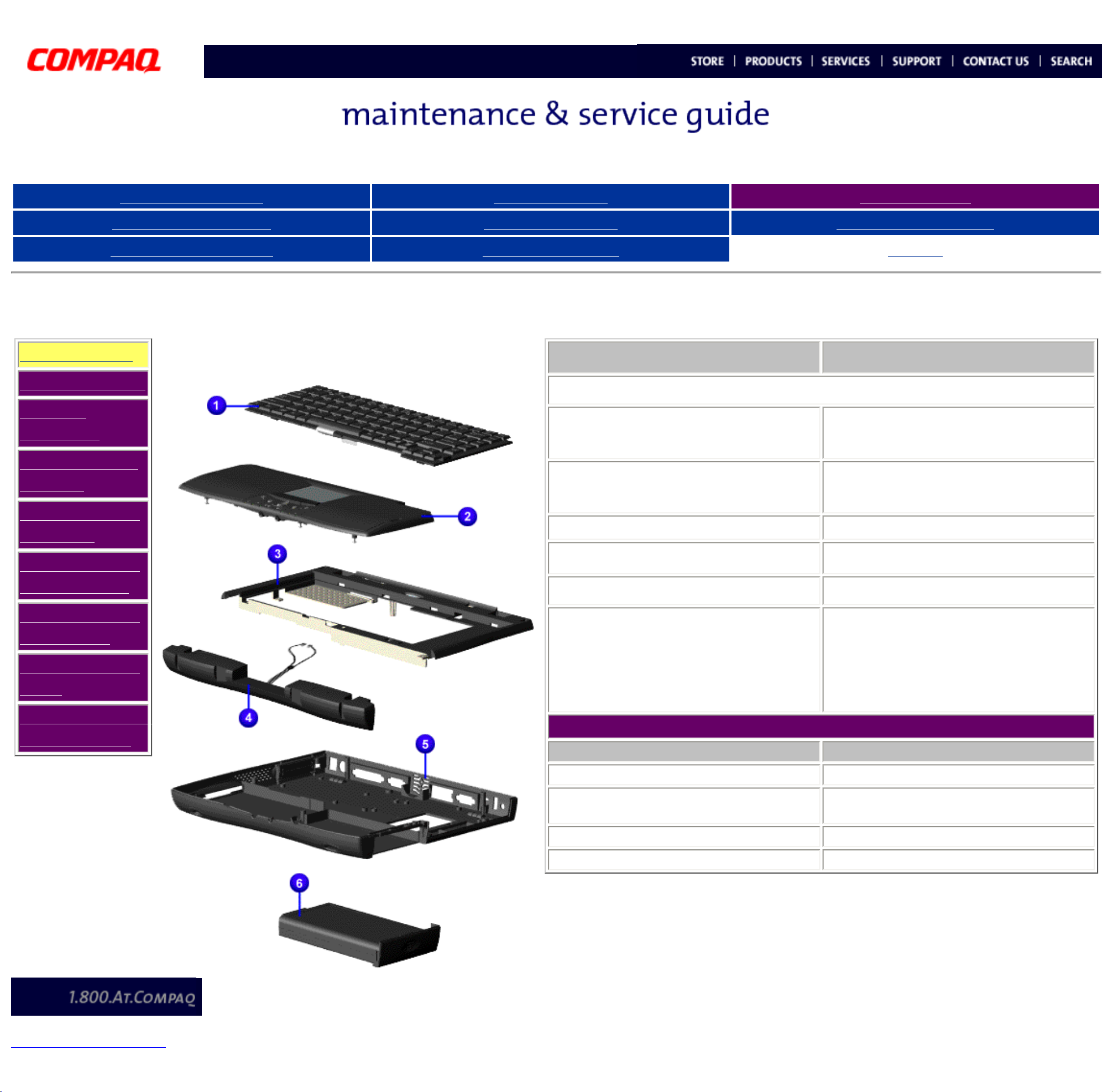
System Unit
Index
Part Description Spare Part Number
1. Keyboard
2. Palmrest Cover w/TouchPad
and Button Board (Models: 1687,
1688, 1690, 1693, 1694)
2. Palmrest Cover w/TouchPad and
Button Board (Models: 1683, 1685,
1688, 1692)
3. Upper CPU Cover w/Power Switch
4. Speaker Assembly w/Cables
142654-001
142653-001
141846-001
148108-001
Hardware Kit
Miscellaneous
Plastics Kit
Miscellaneous
Parts
Documentation
and Software
5. Base Enclosure
6. Battery Pack L ion Enhancement
(Models: 1683, 1685, 1687, 1688,
1690)
6. Battery Pack L ion Enhancement
(Models: 1692, 1693, 1694)
141845-001
388647-001
138-184-001
1600 Series CTO Description Spare Part Number
1. Keyboard
2. Palmrest Cover w/TouchPad and
Button Board
3. Battery
4. Port Replicator
EAB
142654-001
sLiON
400384-001
privacy and legal statement
Page 16

United States January 3, 2003
350-Mhz (Model: 1683) 122698-001
32-MB (Models: 1683,1685, 1687) 122699-001
Presario 1600 Series
Models: 1683, 1685, 1687, 1688, 1690, 1692, 1693, and 1694
Before You Begin Specifications Parts Catalog
Removal Sequence Troubleshooting Battery Operations
Product Description Pin Assignments
Parts Catalog
System Unit
System
Boards
Display
Assembly
Mass Storage
Devices
Miscellaneous
Cable Kit
System Boards
Index
Description Spare Part Number
1. Heatspreader 122702-001
2. Voltage Converter Board 352891-001
3. Modem 56K Data/Fax w/o SRAM 400445-001
3. Modem 56K Data/Fax w/o SRAM-
Intl
4. Processor AMD K6
143848-001
Miscellaneous
Hardware Kit
Miscellaneous
Plastics Kit
Miscellaneous
Parts
Documentation
and Software
privacy and legal statement
5. System Board w/512K Cache 144018-001 (models 1683-1690)
158848-001 (models 1692-1694)
6. Fan Assembly 400444-001
7. System Memory
Page 17

United States January 3, 2003
Presario 1600 Series
Models: 1683, 1685, 1687, 1688, 1690, 1692, 1693, and 1694
Before You Begin Specifications Parts Catalog
Removal Sequence Troubleshooting Battery Operations
Product Description Pin Assignments
Parts Catalog
System Unit
System Boards
Display
Assembly
Mass Storage
Devices
Miscellaneous
Cable Kit
Miscellaneous
Hardware Kit
Miscellaneous
Plastics Kit
Miscellaneous
Parts
Display Assembly
Index
Description
1. Display
12.1 TFT
(Models:
1683,
1685,
1687,
1692)
2. Display
13.3 TFT
w/LVDS
(Model:
1688)
3. Display
14.1 TFT
w/LVDS
(Model:
1690,
1693,
1694)
Spare
Part
Number
142304001
142305001
142306001
Documentation
and Software
privacy and legal statement
Page 18

United States January 3, 2003
1.) 3.2-GB Hard Drive 142309-001 (Model: 1683)
Presario 1600 Series
Models: 1683, 1685, 1687, 1688, 1690, 1692, 1693, and 1694
Before You Begin Specifications Parts Catalog
Removal Sequence Troubleshooting Battery Operations
Product Description Pin Assignments
Parts Catalog
System Unit
System Boards
Display
Assembly
Mass Storage
Devices
Miscellaneous
Cable Kit
Miscellaneous
Mass Storage Devices
Use the scroll down menu for the description and spare part number.
Index
Hardware Kit
Miscellaneous
Plastics Kit
Miscellaneous
Parts
Documentation
and Software
privacy and legal statement
Page 19

United States January 3, 2003
Presario 1600 Series
Models: 1683, 1685, 1687, 1688, 1690, 1692, 1693, and 1694
Before You Begin Specifications Parts Catalog
Removal Sequence Troubleshooting Battery Operations
Product Description Pin Assignments
Parts Catalog
System Unit
System Boards
Display
Assembly
Mass Storage
Devices
Miscellaneous
Cable Kit
Miscellaneous
Hardware Kit
Miscellaneous
Plastics Kit
Miscellaneous
Parts
Documentation
Miscellaneous Cable Kit
Index
Miscellaneous
Cable Kit
Spare Part
Number:
330946-001
1a.
Diskette
Drive
Cable
1b. Hard
Drive
Cable
1c. CD or
DVD
Drive
Cable
1d.
Touchpad
Cable
1e.
Modem
Cable
1
each
1
each
1
each
1
each
1
each
and Software
privacy and legal statement
Page 20

United States January 3, 2003
Presario 1600 Series
Models: 1683, 1685, 1687, 1688, 1690, 1692, 1693, and 1694
Before You Begin Specifications Parts Catalog
Removal Sequence Troubleshooting Battery Operations
Product Description Pin Assignments
Parts Catalog
System Unit
System Boards
Display
Assembly
Mass Storage
Devices
Miscellaneous
Cable Kit
Miscellaneous
Hardware Kit
Miscellaneous Hardware Kit
Index
Miscellaneous
Hardware Kit
Spare Part Number:
346853-001
Description Quantity
1. Hard
Drive
Mounting
Bracket
2. LCD
Guide FPC
3. Spring
Torsion
PCMCIA
1 each
1 each
4 each
Miscellaneous
Plastics Kit
Miscellaneous
Parts
Documentation
and Software
privacy and legal statement
Page 21

United States January 3, 2003
Presario 1600 Series
Models: 1683, 1685, 1687, 1688, 1690, 1692, 1693, and 1694
Before You Begin Specifications Parts Catalog
Removal Sequence Troubleshooting Battery Operations
Product Description Pin Assignments
Parts Catalog
System Unit
System Boards
Display
Assembly
Mass Storage
Devices
Miscellaneous
Cable Kit
Miscellaneous
Hardware Kit
Miscellaneous
Plastics Kit
Miscellaneous Plastics Kit
Index
Miscellaneous Plastics Kit
Spare Part Number: 142657001
Description Quantity
1. Door, Battery Pack 1 each
2. Cover, Memory
Module
3. Door, PCMCIA 1 each
4. Display Hinge
Cover, (Left)
5. Display Hinge
Cover, (Right)
6. CD Drive Guide 1 each
7. Rubber Plug (A) 4 each
8. Rubber Plug (B) 4 each
9. Rubber Foot 8 each
10. Latch (Right) 2 each
1 each
1 each
1 each
Miscellaneous
Parts
Documentation
and Software
privacy and legal statement
11. Latch (Left) 2 each
Page 22

United States January 3, 2003
1. AC Adaptor (Model: 1685) 293831-AA1
Presario 1600 Series
Models: 1683, 1685, 1687, 1688, 1690, 1692, 1693, and 1694
Before You Begin Specifications Parts Catalog
Removal Sequence Troubleshooting Battery Operations
Product Description Pin Assignments
Parts Catalog
System Unit
System Boards
Display
Assembly
Mass Storage
Devices
Miscellaneous
Cable Kit
Miscellaneous
Miscellaneous Parts
2. Port Replicator
3. Return Kit
4. Logo Kit
Index
102270-001
293799-001
141848-001
Hardware Kit
Miscellaneous
Plastics Kit
Miscellaneous
Parts
Documentation
and Software
privacy and legal statement
Page 23

United States January 3, 2003
Belgium Windows 98
Presario 1600 Series
Models: 1683, 1685, 1687, 1688, 1690, 1692, 1693, and 1694
Before You Begin Specifications Parts Catalog
Removal Sequence Troubleshooting Battery Operations
Product Description Pin Assignments
Parts Catalog
System Unit
System Boards
Display
Assembly
Mass Storage
Devices
Miscellaneous
Cable Kit
Miscellaneous
Hardware Kit
Miscellaneous
Plastics Kit
Miscellaneous
Parts
Index
Documentation and Software
Description
Quick Restore CD
[FrontPage Save Results Component]
Reference Guide
QuickFind for Windows, North America,
Latin America, Asia Pacific
QuickFind for Windows, Europe, Middle
East, Africa
*QuickFind is updated monthly. To complete the QuickFind part
number, add the suffix from the table below for the desired month. If
you do not specify the 3-digit suffix, the default is the current month
in which the order is placed.
Spare Part Number
Info. Not Available
Info. Not Available
Info. Not Available
Documentation
and Software
privacy and legal statement
QuickFind Part Number Suffix
Suffix Month Suffix Month
-001 January -007 July
-002 February -008 August
-003 March -009 September
-004 April -010 October
-005 May -011 November
-006 June -012 December
Page 24

United States January 3, 2003
Presario 1600 Series
Models: 1683, 1685, 1687, 1688, 1690, 1692, 1693, and 1694
Before You Begin Specifications Parts Catalog
Removal Sequence Troubleshooting Battery Operations
Product Description Pin Assignments
Removal and Replacement
IMPORTANT:
Removal
Sequence
Cables and
Connectors
Battery Pack
Palmrest Cover
with Touch Pad
Heatspreader
Prior to conducting any removal and/or replacement procedures, you should review and fully understand
the section titled "
Before You Begin".
Cables and Connectors (main page)
Most cables used throughout the unit are ribbon cables. Cables must be handled
with extreme care to avoid damage. Apply only the tension required to seat or
unseat the cables during insertion or removal from the connector. Handle cables
by the connector whenever possible. In all cases, avoid bending, twisting, or
tearing the cables, and ensure that the cables are routed in such a way that they
cannot be caught or snagged by parts being removed or replaced.
Index
Keyboard
Processor
Hard Drive
DVD or
CD Drive
Battery Charger
Board
Modem
Display Panel
Assembly
Upper CPU
Cover
Speaker
Assembly
Diskette Drive
Cables
In order to gain access to the cables, you must first remove the Battery
NOTE:
Pack and the Palmrest Cover with Touch Pad. Those steps are covered in the
Removal Sequence listed to the left.
Use the following precautions when handling cables to avoid damage to the cable
or computer:
● Always handle cables by their connectors.
● Avoid bending, twisting, or pulling on the cables.
● Apply minimum required force when seating or unseating the cables from their connectors.
● Place the cables in such a manner that they cannot be caught or snagged by parts being
removed or replaced.
● Handle flex cables with extreme care, they can tear easily.
Fan Assembly
System Board
Dip Switch
Settings
Memory Module
CAUTION: When servicing these computers, ensure that cables are placed in their
proper location during the reassembly process. Improper cable placement can cause
severe damage to the unit.
Select the Desired Illustration
● Removing a Cable from a ZIF Connector.
● The ribbon cable position for the 4.3-GB and 6.4-GB hard drive.
● The ribbon cable position for the CD or DVD drive.
● The ribbon cable position for the diskette drive.
● The cable position for the speaker assembly.
Plastic Parts
Plastic parts can be damaged by the use of excessive force during disassembly and reassembly. When
handling the plastic parts, use care. Apply pressure only at the points designated in the maintenance
instructions.
privacy and legal statement
Page 25

zif-cable.gif (10259 bytes)
United States January 3, 2003
maintenance & service guide
Compaq Presario 1600 Series
Models 1683, 1685 & 1692, 1687 & 1694, 1688, 1690 & 1693,
CTO
Before You Begin Specifications Parts Catalog
Removal Sequence Troubleshooting Battery Operations
Product Description Pin Assignments
Removal and Replacement
IMPORTANT:
Removal
Sequence
Cables and
Connectors
Battery Pack
Palmrest Cover
with Touch Pad
Heatspreader
Keyboard
Processor
Hard Drive
Prior to conducting any removal and/or replacement procedures, you should review and fully understand
the section titled "
Before You Begin".
ZIF Connectors
Index
Removing a ZIF Cable
The computer uses a zero insertion force (ZIF)
connector for the keyboard cable to the system
board. To remove a cable from a ZIF connector,
lift both corners of the ZIF connector and slide
simultaneously with constant light force.
A ZIF connector and its attached
cable can be easily damaged.
Handle only the connector slide
CAUTION:
when removing or replacing a
cable. Never pull or twist on the
cable while it is connected.
DVD or
CD Drive
Battery
Charger Board
Modem
Display Panel
Assembly
Upper CPU
Cover
Network
Interface Card
Speaker
Assembly
Diskette Drive
Fan Assembly
Back to Cables and Connectors main page.
CAUTION:
When servicing this computer,
ensure that cables are placed in
their proper location during the
reassembly process. Improper
cable placement can damage the
computer.
System Board
Dip Switch
Settings
Memory Module
privacy and legal statement
Page 26

United States January 3, 2003
maintenance & service guide
Compaq Presario 1600 Series
Models 1683, 1685 & 1692, 1687 & 1694, 1688, 1690 & 1693,
CTO
Before You Begin Specifications Parts Catalog
Removal Sequence Troubleshooting Battery Operations
Product Description Pin Assignments
Removal and Replacement
IMPORTANT:
Cables and Connectors
Battery Pack
Palmrest Cover with Touch Pad
Heatspreader
Prior to conducting any removal and/or replacement procedures, you should review and fully understand
the section titled "
Removal Sequence
Before You Begin".
Index
Hard Drive Ribbon
The ribbon cable position for the 4.3-GB and 6.4-GB hard drive
Keyboard
Processor
Hard Drive
DVD or
CD Drive
Battery Charger Board
Modem
Display Panel Assembly
Upper CPU Cover
Network Interface Card
Speaker Assembly
Diskette Drive
Fan Assembly
System Board
Dip Switch Settings
Memory Module
privacy and legal statement
Back to Cables and Connectors main page.
Page 27

United States January 3, 2003
maintenance & service guide
Compaq Presario 1600
Series
Models 1683, 1685 & 1692, 1687 & 1694, 1688,
1690 & 1693, CTO
Before You Begin Specifications Parts Catalog
Removal Sequence Troubleshooting Battery Operations
Product Description Pin Assignments
Index
Removal and Replacement
IMPORTANT:
Removal
Sequence
Cables and
Connectors
Prior to conducting any removal and/or replacement procedures, you should
review and fully understand the section titled "
Before You Begin".
DVD or CD Drive Ribbon
The ribbon cable position for the DVD or CD drive ribbon.
Battery Pack
Palmrest
Cover with
Touch Pad
Heatspreader
Keyboard
Processor
Hard Drive
DVD or
CD Drive
Battery
Charger
Board
Modem
Display Panel
Assembly
Upper CPU
Cover
Back to Cables and Connectors main page.
Network
Interface
Card
Speaker
Assembly
Diskette
Drive
Fan Assembly
System Board
Dip Switch
Settings
Memory
Module
privacy and legal statement
Page 28

United States January 3, 2003
maintenance & service guide
Compaq Presario 1600
Series
Models 1683, 1685 & 1692, 1687 & 1694, 1688,
1690 & 1693, CTO
Before You Begin Specifications Parts Catalog
Removal Sequence Troubleshooting Battery Operations
Product Description Pin Assignments
Index
Removal and Replacement
IMPORTANT:
Removal
Sequence
Cables and
Connectors
Prior to conducting any removal and/or replacement procedures, you should
review and fully understand the section titled "
Before You Begin".
Diskette Drive Ribbon
The ribbon cable position for the diskette drive.
Battery Pack
Palmrest
Cover with
Touch Pad
Heatspreader
Keyboard
Processor
Hard Drive
DVD or
CD Drive
Battery
Charger
Board
Modem
Display Panel
Assembly
Upper CPU
Cover
Network
Interface
Card
Speaker
Assembly
Diskette
Drive
Fan Assembly
System Board
Dip Switch
Settings
Memory
Module
Back to Cables and Connectors main page.
privacy and legal statement
Page 29

United States January 3, 2003
maintenance & service guide
Compaq Presario 1600 Series
Models 1683, 1685 & 1692, 1687 & 1694, 1688, 1690 & 1693,
CTO
Before You Begin Specifications Parts Catalog
Removal Sequence Troubleshooting Battery Operations
Product Description Pin Assignments
Removal and Replacement
IMPORTANT:
Cables and Connectors
Battery Pack
Palmrest Cover with Touch Pad
Heatspreader
Prior to conducting any removal and/or replacement procedures, you should review and fully understand
the section titled "
Removal Sequence
Before You Begin".
Index
Speaker Cable Assembly
The cable position for the speaker assembly.
Keyboard
Processor
Hard Drive
DVD or
CD Drive
Battery Charger Board
Modem
Display Panel Assembly
Upper CPU Cover
Network Interface Card
Speaker Assembly
Diskette Drive
Fan Assembly
System Board
Back to Cables and Connectors main page.
Dip Switch Settings
Memory Module
privacy and legal statement
Page 30

United States January 3, 2003
Presario 1600 Series
Models: 1683, 1685, 1687, 1688, 1690, 1692, 1693, and 1694
Before You Begin Specifications Parts Catalog
Removal Sequence Troubleshooting Battery Operations
Product Description Pin Assignments
Removal and Replacement
IMPORTANT:
Removal
Sequence
Cables and
Connectors
Battery Pack
Palmrest
Cover with
Touch Pad
Prior to conducting any removal and/or replacement procedures, you should review and fully understand
the section titled "
Before You Begin".
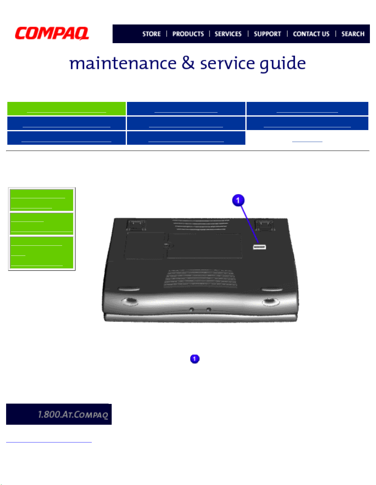
Removing the Battery Pack (step 1)
Index
Slide the battery pack
1.
compartment door down and
remove it from the battery
pack.
Next Step
Heatspreader
Keyboard
Processor
Hard Drive
DVD or
CD Drive
Battery
Charger
Board
Modem
Display Panel
Assembly
Upper CPU
Cover
Speaker
Assembly
Diskette
Drive
Fan
Assembly
System
Board
Dip Switch
Settings
Memory
Module
privacy and legal statement
Page 31

United States January 3, 2003
Presario 1600 Series
Models: 1683, 1685, 1687, 1688, 1690, 1692, 1693, and 1694
Before You Begin Specifications Parts Catalog
Removal Sequence Troubleshooting Battery Operations
Product Description Pin Assignments
Removal and Replacement
IMPORTANT:
Removal
Sequence
Cables and
Connectors
Battery Pack
Palmrest
Cover with
Touch Pad
Heatspreader
Prior to conducting any removal and/or replacement procedures, you should review and fully understand
the section titled "
Before You Begin".
Removing the Battery Pack (step 2)
Index
Pull down on the battery pack tab and
pull the battery pack from the chassis.
To replace the battery pack, reverse the
previous procedures.
Keyboard
Processor
Hard Drive
DVD or
CD Drive
Battery
Charger
Board
Modem
Display Panel
Assembly
Upper CPU
Cover
Network
Interface
Card
Speaker
Assembly
Diskette
Drive
Fan
Assembly
System
Board
Dip Switch
Settings
Memory
Module
privacy and legal statement
Page 32

United States January 3, 2003
Presario 1600 Series
Models: 1683, 1685, 1687, 1688, 1690, 1692, 1693, and 1694
Before You Begin Specifications Parts Catalog
Removal Sequence Troubleshooting Battery Operations
Product Description Pin Assignments
Removal and Replacement
IMPORTANT:
Removal
Sequence
Cables and
Connectors
Battery Pack
Palmrest
Cover with
Touch Pad
Heatspreader
Prior to conducting any removal and/or replacement procedures, you should
review and fully understand the section titled "
Removing the Palmrest Cover
with Touch Pad
Index
Before You Begin".
You must remove the
palmrest cover with
touchpad to gain
access to the interior
components, and it is
the first step in the
sequence of removal
and replacement.
Keyboard
Processor
Hard Drive
DVD or
CD Drive
Battery
Charger
Board
Modem
Display Panel
Assembly
Upper CPU
Cover
Speaker
Assembly
It is not
necessary to
remove the
display panel
NOTE:
To remove the
palmrest cover with
touch pad, complete
the following steps:
assembly to
access the
interior
components of
the computer.
1. Prepare the
computer for
disassembly.
Diskette
Drive
Fan
Assembly
System
Board
Dip Switch
Settings
Memory
Module
privacy and legal statement
2. Close the
computer and
turn the
computer upside
down.
3. Remove four
screws from the
underside of the
computer.
Next Step
Page 33

United States January 3, 2003
Presario 1600 Series
Models: 1683, 1685, 1687, 1688, 1690, 1692, 1693, and 1694
Before You Begin Specifications Parts Catalog
Removal Sequence Troubleshooting Battery Operations
Product Description Pin Assignments
Removal and Replacement
IMPORTANT:
Removal
Sequence
Cables and
Connectors
Battery Pack
Palmrest
Cover with
Touch Pad
Heatspreader
Keyboard
Processor
Hard Drive
Prior to conducting any removal and/or replacement procedures, you should review
and fully understand the section titled "
Removing the Palmrest Cover with
Touch Pad (steps 4 & 5)
Index
Before You Begin".
Previous Step
4. Turn the
computer
over (right
side up), pull
forward on
the display
latches to
release and
open the
display
assembly.
DVD or
CD Drive
Battery
Charger
Board
Modem
Display Panel
Assembly
Upper CPU
Cover
Speaker
Assembly
Diskette
Drive
Fan
Assembly
5. Lift up front
end of the
palmrest
cover with
touch pad and
remove it
from the
Next Step
groove in the
chassis.
System
Board
Dip Switch
Settings
Memory
Module
privacy and legal statement
Page 34

United States January 3, 2003
Presario 1600 Series
Models: 1683, 1685, 1687, 1688, 1690, 1692, 1693, and 1694
Before You Begin Specifications Parts Catalog
Removal Sequence Troubleshooting Battery Operations
Product Description Pin Assignments
Removal and Replacement
IMPORTANT:
Removal
Sequence
Cables and
Connectors
Battery Pack
Palmrest
Cover with
Touch Pad
Heatspreader
Keyboard
Processor
Hard Drive
DVD or
CD Drive
Battery
Charger
Board
Modem
Display Panel
Assembly
Upper CPU
Cover
Speaker
Assembly
Diskette
Drive
Fan
Assembly
System
Board
Dip Switch
Settings
Memory
Module
Prior to conducting any removal and/or replacement procedures, you should review
and fully understand the section titled "
Removing the Palmrest Cover with
Touch Pad (step 6)
Index
Before You Begin".
Previous Steps
6. Tilt the
palmrest cover
with touch pad,
allowing it to
rest on top of
the keyboard,
and disconnect
the flex cable
from the LIF
connector on
the palmrest
cover.
CAUTION: When
replacing the
palmrest cover
with touch pad,
ensure that the
cable is fully
inserted into
the LIF
connector on
the system
board. If the
metal end
should come in
contact with
the keyboard,
damage may
occur to the
computer.
To replace the
palmrest cover
with touch pad,
reverse the
previous
procedures.
privacy and legal statement
When
replacing the
palm rest
cover ensure
the cable is
NOTE:
properly
routed
through the
slot on the
Upper CPU
cover.
Page 35

United States January 3, 2003
Presario 1600 Series
Models: 1683, 1685, 1687, 1688, 1690, 1692, 1693, and 1694
Before You Begin Specifications Parts Catalog
Removal Sequence Troubleshooting Battery Operations
Product Description Pin Assignments
Removal and Replacement
IMPORTANT:
Removal
Sequence
Cables and
Connectors
Battery Pack
Palmrest
Cover with
Touch Pad
Heatspreader
Keyboard
Prior to conducting any removal and/or replacement procedures, you should
review and fully understand the section titled "
Heatspreader Removal (steps 1 - 3)
Prepare the computer for disassembly.
1.
2. Remove the palmrest cover with touch pad.
3. Gently lift and turn the keyboard over allowing it to rest on top of the
Palmrest Cover with Touchpad slot opening.
Index
Before You Begin".
Processor
Hard Drive
DVD or
CD Drive
Battery
Charger
Board
Modem
Display Panel
Assembly
Upper CPU
Cover
Speaker
Assembly
Diskette
Drive
Next Step
Fan Assembly
System Board
Dip Switch
Settings
Memory
Module
privacy and legal statement
Page 36

United States January 3, 2003
Presario 1600 Series
Models: 1683, 1685, 1687, 1688, 1690, 1692, 1693, and 1694
Before You Begin Specifications Parts Catalog
Removal Sequence Troubleshooting Battery Operations
Product Description Pin Assignments
Removal and Replacement
IMPORTANT:
Removal
Sequence
Cables and
Connectors
Battery Pack
Palmrest
Cover with
Touch Pad
Prior to conducting any removal and/or replacement procedures, you should review and
fully understand the section titled "
Heatspreader Removal (step 4)
Index
Before You Begin".
Previous Steps
4. Remove the
screws from the
heatspreader
and lift out of the
chassis.
Heatspreader
Keyboard
Processor
Hard Drive
DVD or
CD Drive
Battery
Charger
Board
Modem
Display Panel
Assembly
Upper CPU
Cover
Network
Interface
Card
To replace the
heatspreader, reverse
the previous
procedures.
Speaker
Assembly
Diskette
Drive
Fan
Assembly
System
Board
Dip Switch
Settings
Memory
Module
privacy and legal statement
Page 37

United States January 3, 2003
Presario 1600 Series
Models: 1683, 1685, 1687, 1688, 1690, 1692, 1693, and 1694
Before You Begin Specifications Parts Catalog
Removal Sequence Troubleshooting Battery Operations
Product Description Pin Assignments
Removal and Replacement
IMPORTANT:
Removal
Sequence
Cables and
Connectors
Battery Pack
Palmrest
Cover with
Touch Pad
Prior to conducting any removal and/or replacement procedures, you should review and
fully understand the section titled "
Removing the Keyboard
Before You Begin".
Index
Prepare the
1.
computer for
disassembly.
2. Remove the
palmrest cover
with touch pad.
Heatspreader
Keyboard
Processor
Hard Drive
DVD or
CD Drive
Battery
Charger
Board
Modem
Display Panel
Assembly
Upper CPU
Cover
Speaker
Assembly
3. Gently lift Zif
Socket and
remove
keyboard.
Diskette
Drive
Fan
Assembly
System
Board
Dip Switch
Settings
Memory
Module
privacy and legal statement
Page 38

United States January 3, 2003
Presario 1600 Series
Models: 1683, 1685, 1687, 1688, 1690, 1692, 1693, and 1694
Before You Begin Specifications Parts Catalog
Removal Sequence Troubleshooting Battery Operations
Product Description Pin Assignments
Removal and Replacement
IMPORTANT:
Removal
Sequence
Cables and
Connectors
Battery Pack
Palmrest
Cover with
Touch Pad
Prior to conducting any removal and/or replacement procedures, you should review and
fully understand the section titled "
Removing the Processor
Before You Begin".
Index
Prepare the
1.
computer for
disassembly.
2. Remove the
palmrest cover
with touch pad.
Heatspreader
Keyboard
Processor
Hard Drive
DVD or
CD Drive
Battery
Charger
Board
Modem
Display Panel
Assembly
Upper CPU
Cover
Speaker
Assembly
Diskette
Drive
Fan
Assembly
3. Remove the
keyboard.
4. Remove the
heatspreader.
5. Insert a small
blade screw
driver into the
top slot opening
on the processor
and push away
from the display
to release the
processor from
the chassis slot.
6. Lift the processor
out of the
processor chassis
slot.
Next Step (Replacing
the Processor)
System
Board
Dip Switch
Settings
Memory
Module
privacy and legal statement
Page 39

United States January 3, 2003
Presario 1600 Series
Models: 1683, 1685, 1687, 1688, 1690, 1692, 1693, and 1694
Before You Begin Specifications Parts Catalog
Removal Sequence Troubleshooting Battery Operations
Product Description Pin Assignments
Removal and Replacement
IMPORTANT:
Removal
Sequence
Cables and
Connectors
Battery Pack
Palmrest
Cover with
Touch Pad
Heatspreader
Keyboard
Processor
Hard Drive
Prior to conducting any removal and/or replacement procedures, you should
review and fully understand the section titled "
Replacing the Processor
Index
Before You Begin".
Previous Step
(Removing the
Processor)
The notch
on the
upper left
corner of
the
processor
serves as
an
orientation
indicator.
DVD or
CD Drive
Battery
Charger
Board
Modem
Display Panel
Assembly
Upper CPU
Cover
Network
Interface
Card
Speaker
Assembly
IMPORTANT:
1. Insert the
processor into
the slot on the
system board.
Align the
notch on
the left
corner of
the
processor
with the
notch on
the left
corner of
the
processor
chassis
slot.
Diskette
Drive
Fan
Assembly
System
Board
Dip Switch
Settings
Memory
Module
When installing
the processor
into the chassis
slot, be sure
that the hole
pattern on the
chassis slot lines
NOTE:
up with the pins
on the
processor.
The processor
should drop into
the socket
without any
force.
2. Insert a small
blade screw
driver into the
bottom slot
opening on the
processor and
push toward the
display to lock
the processor.
privacy and legal statement
Return
Page 40

United States January 3, 2003
Presario 1600 Series
Models: 1683, 1685, 1687, 1688, 1690, 1692, 1693, and 1694
Before You Begin Specifications Parts Catalog
Removal Sequence Troubleshooting Battery Operations
Product Description Pin Assignments
Removal and Replacement
IMPORTANT:
Removal
Sequence
Cables and
Connectors
Battery Pack
Palmrest
Cover with
Touch Pad
Heatspreader
Keyboard
Processor
Hard Drive
DVD or
CD Drive
Battery
Charger
Board
Modem
Prior to conducting any removal and/or replacement procedures, you should review
and fully understand the section titled "
Removing the Hard Drive (steps 1 -
4)
Before You Begin".
Index
Prepare the
1.
computer for
disassembly.
2. Remove the
palmrest cover
with touch pad.
3. Remove the
keyboard.
4. Remove two
screws from the
hard drive
mounting
bracket and lift
out the hard
drive with drive
mounting
bracket
attached.
Next Step
Display Panel
Assembly
Upper CPU
Cover
Speaker
Assembly
Diskette
Drive
Fan
Assembly
System
Board
Dip Switch
Settings
Memory
Module
privacy and legal statement
Page 41

United States January 3, 2003
Presario 1600 Series
Models: 1683, 1685, 1687, 1688, 1690, 1692, 1693, and 1694
Before You Begin Specifications Parts Catalog
Removal Sequence Troubleshooting Battery Operations
Product Description Pin Assignments
Removal and Replacement
IMPORTANT:
Removal
Sequence
Cables and
Connectors
Battery Pack
Palmrest
Cover with
Touch Pad
Prior to conducting any removal and/or replacement procedures, you should review
and fully understand the section titled "
Removing the Hard Drive (step 5)
Index
Before You Begin".
Previous Steps
5. Disconnect the
hard drive
data cable
from the hard
drive and
remove from
the chassis.
Heatspreader
Keyboard
Processor
Hard Drive
DVD or
CD Drive
Battery
Charger
Board
Modem
Display Panel
Assembly
Upper CPU
Cover
Speaker
Assembly
Next Step
Diskette
Drive
Fan
Assembly
System
Board
Dip Switch
Settings
Memory
Module
privacy and legal statement
Page 42

United States January 3, 2003
Presario 1600 Series
Models: 1683, 1685, 1687, 1688, 1690, 1692, 1693, and 1694
Before You Begin Specifications Parts Catalog
Removal Sequence Troubleshooting Battery Operations
Product Description Pin Assignments
Removal and Replacement
IMPORTANT:
Removal
Sequence
Cables and
Connectors
Battery Pack
Palmrest
Cover with
Touch Pad
Heatspreader
Keyboard
Processor
Prior to conducting any removal and/or replacement procedures, you should review and
fully understand the section titled "
Removing the Hard Drive (step 6)
Before You Begin".
Index
Previous Steps
6. Remove four
screws from
the hard
drive
mounting
bracket.
To replace the hard
drive and hard drive
mounting bracket,
reverse the
previous
procedures.
Hard Drive
DVD or
CD Drive
Battery
Charger
Board
Modem
Display Panel
Assembly
Upper CPU
Cover
Speaker
Assembly
Diskette
Drive
Return
Fan
Assembly
System
Board
Dip Switch
Settings
Memory
Module
privacy and legal statement
Page 43

United States January 3, 2003
Presario 1600 Series
Models: 1683, 1685, 1687, 1688, 1690, 1692, 1693, and 1694
Before You Begin Specifications Parts Catalog
Removal Sequence Troubleshooting Battery Operations
Product Description Pin Assignments
Removal and Replacement
IMPORTANT:
Removal
Sequence
Cables and
Connectors
Battery Pack
Palmrest
Cover with
Touch Pad
Heatspreader
Keyboard
Processor
Hard Drive
DVD or
CD Drive
Battery
Charger
Board
Prior to conducting any removal and/or replacement procedures, you should review
and fully understand the section titled "
Removal of DVD or CD Drive
Before You Begin".
Index
Prepare the
1.
computer for
disassembly.
2. Remove the
palmrest cover
with touch pad.
3. Remove the
keyboard.
4. Remove the
heatspreader.
5. Remove two
screws located at
the back of the
DVD or CD drive.
Next Step
Modem
Display Panel
Assembly
Upper CPU
Cover
Speaker
Assembly
Diskette
Drive
Fan
Assembly
System
Board
Dip Switch
Settings
Memory
Module
privacy and legal statement
Page 44

United States January 3, 2003
Presario 1600 Series
Models: 1683, 1685, 1687, 1688, 1690, 1692, 1693, and 1694
Before You Begin Specifications Parts Catalog
Removal Sequence Troubleshooting Battery Operations
Product Description Pin Assignments
Removal and Replacement
IMPORTANT:
Removal
Sequence
Cables and
Connectors
Battery Pack
Palmrest
Cover with
Touch Pad
Heatspreader
Prior to conducting any removal and/or replacement procedures, you should review and
fully understand the section titled "
Removal of DVD or CD Drive (step 6)
Index
Before You Begin".
Previous Steps
6. Remove two
screws from
the base
enclosure
which
secures the
DVD or CD
drive to the
chassis.
Keyboard
Processor
Hard Drive
DVD or
CD Drive
Battery
Charger
Board
Modem
Display Panel
Assembly
Upper CPU
Cover
Speaker
Assembly
Next Step
Diskette
Drive
Fan
Assembly
System
Board
Dip Switch
Settings
Memory
Module
privacy and legal statement
Page 45

United States January 3, 2003
Presario 1600 Series
Models: 1683, 1685, 1687, 1688, 1690, 1692, 1693, and 1694
Before You Begin Specifications Parts Catalog
Removal Sequence Troubleshooting Battery Operations
Product Description Pin Assignments
Removal and Replacement
IMPORTANT:
Removal
Sequence
Cables and
Connectors
Battery Pack
Palmrest
Cover with
Touch Pad
Heatspreader
Prior to conducting any removal and/or replacement procedures, you should review
and fully understand the section titled "
Removal of DVD or CD Drive (step 7)
Index
Before You Begin".
Previous Steps
7. Disconnect the
DVD or CD
drive cable
from the DVD
or CD drive
and remove
the DVD or CD
drive from the
chassis.
Keyboard
Processor
Hard Drive
DVD or
CD Drive
Battery
Charger
Board
Modem
Display Panel
Assembly
Upper CPU
Cover
Speaker
Assembly
To replace the DVD
or CD drive, reverse
the previous
procedures.
Return
Diskette
Drive
Fan
Assembly
System
Board
Dip Switch
Settings
Memory
Module
privacy and legal statement
Page 46

United States January 3, 2003
Presario 1600 Series
Models: 1683, 1685, 1687, 1688, 1690, 1692, 1693, and 1694
Before You Begin Specifications Parts Catalog
Removal Sequence Troubleshooting Battery Operations
Product Description Pin Assignments
Removal and Replacement
IMPORTANT:
Removal
Sequence
Cables and
Connectors
Battery Pack
Palmrest
Cover with
Touch Pad
Heatspreader
Keyboard
Processor
Hard Drive
DVD or
CD Drive
Battery
Charger
Board
Modem
Prior to conducting any removal and/or replacement procedures, you should review
and fully understand the section titled "
Removing the Battery Charger
Board
Before You Begin".
Index
Prepare the
1.
computer for
disassembly.
2. Remove the
palmrest cover
with touch pad.
3. Remove the
keyboard.
4. Remove the
heatspreader.
5. Remove the hard
drive.
6. Remove one scre
from the battery
charger board,
unplug the board
from the
connector on the
system board,
and lift out the
chassis.
Display Panel
Assembly
Upper CPU
Cover
Speaker
Assembly
Diskette
Drive
Fan
Assembly
System
Board
Dip Switch
Settings
Memory
Module
To replace the battery
charger board, reverse
the previous
procedures.
When replacing
the battery
charger board,
NOTE:
ensure the pins
are aligned with
the connector
on the system
board.
privacy and legal statement
Page 47

United States January 3, 2003
Presario 1600 Series
Models: 1683, 1685, 1687, 1688, 1690, 1692, 1693, and 1694
Before You Begin Specifications Parts Catalog
Removal Sequence Troubleshooting Battery Operations
Product Description Pin Assignments
Removal and Replacement
IMPORTANT:
Removal
Sequence
Cables and
Connectors
Battery Pack
Palmrest
Cover with
Touch Pad
Heatspreader
Keyboard
Processor
Hard Drive
DVD or
CD Drive
Battery
Charger
Board
Prior to conducting any removal and/or replacement procedures, you should review
and fully understand the section titled "
Removing the Modem (steps 1 - 5)
Before You Begin".
Index
Prepare the
1.
computer for
disassembly.
2. Remove the
palmrest cover
with touch pad.
3. Remove the
keyboard.
4. Remove the
heatspreader.
5. Remove three
screws securing
modem and pull
the modem off
the connector on
the system
board.
Next Step
Modem
Display Panel
Assembly
Upper CPU
Cover
Speaker
Assembly
Diskette
Drive
Fan
Assembly
System
Board
Dip Switch
Settings
Memory
Module
privacy and legal statement
Page 48

United States January 3, 2003
Presario 1600 Series
Models: 1683, 1685, 1687, 1688, 1690, 1692, 1693, and 1694
Before You Begin Specifications Parts Catalog
Removal Sequence Troubleshooting Battery Operations
Product Description Pin Assignments
Removal and Replacement
IMPORTANT:
Removal
Sequence
Cables and
Connectors
Battery Pack
Palmrest
Cover with
Touch Pad
Heatspreader
Prior to conducting any removal and/or replacement procedures, you should review
and fully understand the section titled "
Removing the Modem (step 6)
Index
Before You Begin".
Previous Steps
6. Disconnect the
modem cable
from the
modem.
To replace the
modem, reverse the
previous procedures.
Keyboard
Processor
Hard Drive
DVD or
CD Drive
Battery
Charger
Board
Modem
Display Panel
Assembly
Upper CPU
Cover
Speaker
Assembly
Return
Diskette
Drive
Fan
Assembly
System
Board
Dip Switch
Settings
Memory
Module
privacy and legal statement
Page 49

United States January 3, 2003
Presario 1600 Series
Models: 1683, 1685, 1687, 1688, 1690, 1692, 1693, and 1694
Before You Begin Specifications Parts Catalog
Removal Sequence Troubleshooting Battery Operations
Product Description Pin Assignments
Removal and Replacement
IMPORTANT:
Removal
Sequence
Cables and
Connectors
Battery Pack
Palmrest
Cover with
Touch Pad
Heatspreader
Keyboard
Processor
Hard Drive
DVD or
CD Drive
Battery
Charger
Board
Modem
Prior to conducting any removal and/or replacement procedures, you should review and
fully understand the section titled "
Removing the Display Panel Assembly
Before You Begin".
Index
Prepare the
1.
computer for
disassembly.
2. Remove the
palmrest cover
with touch pad.
3. Remove the
keyboard.
4. Remove the
heatspreader.
5. Remove the
modem.
6. Disconnect the
backlight cable
attached to the
display panel
assembly from
the connector on
the system
board.
Display Panel
Assembly
Upper CPU
Cover
Speaker
Assembly
Diskette
Drive
Fan
Assembly
System
Board
Dip Switch
Settings
Memory
Module
Next Step
privacy and legal statement
Page 50

United States January 3, 2003
Presario 1600 Series
Models: 1683, 1685, 1687, 1688, 1690, 1692, 1693, and 1694
Before You Begin Specifications Parts Catalog
Removal Sequence Troubleshooting Battery Operations
Product Description Pin Assignments
Removal and Replacement
IMPORTANT:
Removal
Sequence
Cables and
Connectors
Battery Pack
Palmrest
Cover with
Touch Pad
Heatspreader
Keyboard
Processor
Prior to conducting any removal and/or replacement procedures, you should review and
fully understand the section titled "
Removing the Display Panel Assembly
(step 7)
Index
Before You Begin".
Previous Step
7. Disconnect the
flex data cable
attached to the
display panel
assembly
from either
the TFT
connector
or the Low
Voltage
Differential
Signal (LVDS)
Hard Drive
DVD or
CD Drive
Battery
Charger
Board
Modem
Display Panel
Assembly
Upper CPU
Cover
Speaker
Assembly
Diskette
Drive
connector
on the system
board.
Next Step
Fan
Assembly
System
Board
Dip Switch
Settings
Memory
Module
privacy and legal statement
 Loading...