

Compaq 1600R - ProLiant - 128 MB RAM, ProLiant 1200, ProLiant 1600 Maintenance And Service Manual
Page 1

. . . . . . . . . . . . . . . . . . . . . . . . . . . . . . . . . .
. . . . .
ProLiant 1600 and
ProLiant 1200 Servers
Maintenance and Service Guide
First Edition (October 1997)
Document Part Number 149036-001
Spares Part Number 298015-001
Compaq Computer Corporation
Page 2

Notice
The information in this publication is subject to change without notice.
COMPAQ COMPUTER CORPORATION SHALL NOT BE LIABLE FOR TECHNICAL
OR EDITORIAL ERRORS OR OMISSIONS CONTAINED HEREIN, NOR FOR
INCIDENTAL OR CONSEQUENTIAL DAMAGES RESULTING FROM THE
FURNISHING, PERFORMANCE, OR USE OF THIS MATERIAL. THIS
INFORMATION IS PROVIDED “AS IS” AND COMPAQ COMPUTER
CORPORATION DISCLAIMS ANY WARRANTIES, EXPRESS, IMPLIED OR
STATUTORY AND EXPRESSLY DISCLAIMS THE IMPLIED WARRANTIES OF
MERCHANTABILITY, FITNESS FOR PARTICULAR PURPOSE, GOOD TITLE AND
AGAINST INFRINGEMENT.
This publication contains information protected by copyright. No part of this publication
may be photocopied or reproduced in any form without prior written consent from Compaq
Computer Corporation.
1997 Compaq Computer Corporation.
All rights reserved. Printed in the U.S.A.
The software described in this guide is furnished under a license agreement or
nondisclosure agreement. The software may be used or copied only in accordance with the
terms of the agreement.
Compaq, Compaq Insight Manager, QuickFind, registered United States Patent and
Trademark Office.
SoftPaq is a trademark and/or service mark of Compaq Computer Corporation.
Product names mentioned herein may be trademarks and/or registered trademarks of their
respective companies.
Compaq ProLiant 1600 and Pro Liant 1200 Servers
Maintenance and Service Guide
First Edition (October 1997)
Document Part Number 149036-001
Spares Part Number 298015-001
Page 3

. . . . . . . . . . . . . . . . . . . . . . . . . . . . . . . . . .
. . . . .
iii
Contents
Preface
About This Guide
Symbols........................................................................................................................viii
Technician Notes..........................................................................................................viii
Where to Go for Help.....................................................................................................ix
Integrated Management Display.............................................................................ix
Electronic Services..................................................................................................ix
Compaq CDs............................................................................................................x
Compaq Web Site....................................................................................................x
Other Information Sources......................................................................................xi
Chapter 1
Illustrated Parts Catalog
Mechanical Parts Exploded View............................................................................... 1-1
System Components Exploded View.......................................................................... 1-2
Spares Parts List.......................................................................................................... 1-3
Chapter 2
Removal and Replacement Procedures
Electrostatic Discharge Information ........................................................................... 2-1
Symbols in Equipment ................................................................................................ 2-2
Preparation Procedures ............................................................................................... 2-2
Rack Warnings..................................................................................................... 2-3
Server Warnings and Precautions ........................................................................ 2-4
Front Bezel.................................................................................................................. 2-5
Feet.............................................................................................................................. 2-6
Left Side Access Panel................................................................................................ 2-7
Top Cover ................................................................................................................... 2-8
Right Side Access Panel.............................................................................................. 2-9
Mass Storage............................................................................................................. 2-10
Hot-Plug Drive Cage.......................................................................................... 2-11
CD-ROM Drive.................................................................................................. 2-12
Diskette Drive.................................................................................................... 2-13
Compaq ProLiant 1600 and ProLiant 1200 Servers Maintenance and Service Guide
Page 4

. . . . . . . . . . . . . . . . . . . . . . . . . . . . . . . . . .
. . . . .
iv Contents
Removal and Replacement Procedures
Cable Diagrams......................................................................................................... 2-14
System I/O Board Cage............................................................................................. 2-16
I/O Fan ...................................................................................................................... 2-17
Power Switch.............................................................................................................2-18
Processor Cage Assembly......................................................................................... 2-20
Processor Cage................................................................................................... 2-20
Pentium II Adapter Board.................................................................................. 2-22
Terminator Board............................................................................................... 2-23
Processors .......................................................................................................... 2-24
Processor Power Module................................................................................... 2-26
Memory Expansion Board................................................................................. 2-28
Memory.............................................................................................................. 2-29
Power Supply............................................................................................................ 2-33
Backplane Board....................................................................................................... 2-34
External Replacement Battery .................................................................................. 2-35
(continued)
Chapter 3
Diagnostic Tools
Utility Access.............................................................................................................. 3-2
Power-On Self-Test (POST)....................................................................................... 3-4
Diagnostics Software................................................................................................. 3-17
Primary Processor Test Error Codes ................................................................. 3-18
Memory Test Error Codes ................................................................................. 3-19
Keyboard Test Error Codes ............................................................................... 3-20
Parallel Printer Test Error Codes....................................................................... 3-21
Video Display Unit Test Error Codes................................................................ 3-21
Diskette Drive Test Error Codes........................................................................ 3-22
Monochrome Video Board Test Error Codes.................................................... 3-22
Serial Test Error Codes...................................................................................... 3-23
Modem Communications Test Error Codes ...................................................... 3-23
Fixed Disk Drive Test Error Codes.................................................................... 3-24
Tape Drive Test Error Codes............................................................................. 3-25
Advanced VGA Board Test Error Codes........................................................... 3-26
Compaq Network Interface Cards Test Error Codes......................................... 3-27
SCSI Fixed Disk Drive Test Error Codes.......................................................... 3-28
SCSI/IDE CD-ROM Drive Test Error Codes.................................................... 3-28
Page 5

. . . . . . . . . . . . . . . . . . . . . . . . . . . . . . . . . .
. . . . .
v
Diagnostic Tools
SCSI Tape Drive Test Error Codes.................................................................... 3-29
Server Manager/R Board Test Error Codes....................................................... 3-29
Pointing Device Interface Test Error Codes...................................................... 3-30
Drive Array Advanced Diagnostics (DAAD)............................................................3-31
Integrated Management Log..................................................................................... 3-42
Multiple Ways of Viewing the Log.................................................................... 3-42
Compaq Survey Utility....................................................................................... 3-43
List of Events..................................................................................................... 3-44
Rapid Recovery Services........................................................................................... 3-46
Automatic Server Recovery-2............................................................................ 3-46
Server Health Logs............................................................................................. 3-55
Storage Fault Recovery Tracking....................................................................... 3-59
Storage Automatic Reconstruction.................................................................... 3-59
Network Interface Fault Recovery Tracking......................................................3-59
Memory Fault Recovery Tracking..................................................................... 3-59
Remote Service Features........................................................................................... 3-60
ROMPaq.................................................................................................................... 3-61
Compaq Insight Manager.......................................................................................... 3-61
Features of Compaq Insight Management......................................................... 3-61
Compaq Insight Management Software Architecture........................................ 3-62
(continued)
Chapter 4
Connectors, Switches, and Jumpers
Compaq ProLiant 1600 Processor Board.................................................................... 4-1
Components ......................................................................................................... 4-1
Rear Connectors and LEDs.................................................................................. 4-2
SW1 - Bus/Core Ratio Settings............................................................................ 4-3
Compaq ProLiant 1200 Processor Board.................................................................... 4-4
Components ......................................................................................................... 4-4
Rear Connectors and LEDs.................................................................................. 4-5
SW1 - Bus/Core Ratio Settings............................................................................ 4-6
System I/O Board........................................................................................................ 4-7
Components ......................................................................................................... 4-7
Rear Connectors................................................................................................... 4-8
SW1 - System Maintenance Switch..................................................................... 4-9
Compaq ProLiant 1600 and ProLiant 1200 Servers Maintenance and Service Guide
Page 6

. . . . . . . . . . . . . . . . . . . . . . . . . . . . . . . . . .
. . . . .
vi Contents
Chapter 5
Physical and Operating Specifications
System Unit................................................................................................................. 5-2
Power Supply.............................................................................................................. 5-3
Compaq ProLiant 1600........................................................................................ 5-3
Compaq ProLiant 1200........................................................................................ 5-4
Dual Inline Memory Modules (DIMMs).................................................................... 5-4
1.44-MB Diskette Drive.............................................................................................. 5-5
16X CD-ROM Drive................................................................................................... 5-6
Index
Page 7

. . . . . . . . . . . . . . . . . . . . . . . . . . . . . . . . . .
. . . . .
vii
Preface
About This Guide
This Maintenance and Service Guide is a troubleshooting guide that can be used for
reference when servicing Compaq ProLiant 1600 and ProLiant 1200 Servers.
WARNING: To reduce the risk of personal injury from
electrical shock and hazardous ener g y levels , only
authorized service technicians should attem pt to r epair this
equipment. Improper r epairs co uld cr eate co nditio ns that
are hazardous.
IMPORTANT: T he ins t allatio n o f o ptio ns and the s er vicing of this
product shall be perform ed by individuals w ho ar e kno wledgeable
of the procedures, precautio n s , and haz ar ds as s ociated with
equipment containing hazardous energ y cir cuits .
Compaq Computer Corporation reserves the right to make changes to Compaq
ProLiant 1600 and ProLiant 1200 Servers without notice. This document contains the
following chapters:
■
Chapter 1 - Illustrated Parts Catalog
Contains Compaq ProLiant 1600 and ProLiant 1200 Servers exploded views and
spares parts list.
■
Chapter 2 - Removal and Replacement Procedures
Contains steps for removing and replacing Compaq ProLiant 1600 and ProLiant 1200
Servers spare parts.
■
Chapter 3 - Diagnostic Tools
Describes software and firmware diagnostic tools available for all Compaq
server products.
■
Chapter 4 - Connectors, Switches, and Jumpers
Provides connector, switch, and jumper information for the Compaq ProLiant 1600
and ProLiant 1200 Servers.
■
Chapter 5 - Physical and Operating Specifications
Provides the physical and operating specifications for the Compaq ProLiant 1600 and
ProLiant 1200 Servers.
Compaq ProLiant 1600 and ProLiant 1200 Servers Maintenance and Service Guide
Page 8

. . . . . . . . . . . . . . . . . . . . . . . . . . . . . . . . . .
WARNING:
. . . . .
viii About This Guide
Symbols
The following text and symbols mark special information throughout this guide:
Text set off in this manner indicates that failure to
follow directions in the warning could result in bodily harm or
loss of life.
CAUTION:
follow directions co uld res ult in dam ag e to equipm ent o r lo s s
of data.
IMPORTANT:
information or
specific instructions.
Text set off in this manner pres ents co m m entar y, s idelig hts ,
NOTE:
or interesting points of inf o r m atio n.
Technician Notes
Text set off in this manner indicates that failure to
Text set off in this manner pres ents clar if ying
Compaq ProLiant 1600 and ProLiant 1200 Servers Maintenance and Service Guide
Page 9

. . . . . . . . . . . . . . . . . . . . . . . . . . . . . . . . . .
. . . . .
ix
WARNING:
electrical shock and hazardous ener g y levels , do not exceed
the level of repair specified in these pr o cedur es . Becaus e o f
the complexity of the individual boar ds and s ubas s em blies ,
do not attempt to make repairs at the component level or to
make modifications to any pr inted w ir ing bo ar d. Improper
repairs could create conditions that ar e haz ar do us .
WARNING:
to the equipment:
If the system has multiple power supplies,
■
disconnect power fro m the system by
unplugging all power cords f ro m the power
supplies.
Do not disable the power co r d g r o unding plug.
■
The grounding plug is an im po rt ant s af ety
feature.
Plug the power cord into a g r o unded ( ear thed)
■
electrical outlet that is easily accessible at all
times.
CAUTION:
provide at least
12 inches (30.5 cm) of clearance at the f r o nt and back o f
the computer.
To reduce the risk of personal injury from
To reduce the risk of electric shock or damage
To properly ventilate your sys tem , you must
IMPORTANT:
modification of a printed w ir ing bo ar d m ay vo id any w arr anty.
Any indication of repair at the compo n ent level o r
Compaq ProLiant 1600 and ProLiant 1200 Servers Maintenance and Service Guide
Page 10

. . . . . . . . . . . . . . . . . . . . . . . . . . . . . . . . . .
. . . . .
x About This Guide
Where to Go for Help
Major sources of additional information are as follows:
■
Integrated Management Display
■
Electronic services
■
Compaq CDs
■
Compaq Web Site (
■
Other information sources
http://www.compaq.com
Integrated Manage ment Display
The Compaq Integrated Management Display (IMD) is an integrated, 16x4 character
display mounted on the front of the server. This display provides easy-to-use, menu-driven
access to server information, including model number, LCD firmware revision, and POST
operations.
Electronic Services
Users can download drivers, patches, and Compaq service updates from the following
sources:
■
Internet: Questions can be submitted to Compaq Technical Support staff using the
electronic mail address:
using the address: FTP.COMPAQ.COM. Enter "anonymous" for the user name at
the log-in prompt and enter your full Internet electronic mail address for the
password. You can access the Compaq World Wide Web site through the Uniform
Resource Locator (URL):
■
Other online services: CompuServe, Prodigy, and America Online, can be used if
you are a member. Use the keywords below to access Compaq materials:
support@compaq.com
http://www. compaq.com.
)
. Compaq files can be accessed
❏
CompuServe - The keywords are “GO COMPAQ”.
❏
Prodigy - Choose the “Jump” navigation command, then enter the keyword
“COMPAQ”.
❏
America Online - Enter the keyword “COMPAQ”.
■
Compaq Download Facility: Call 1-281-518-1418
Compaq ProLiant 1600 and ProLiant 1200 Servers Maintenance and Service Guide
Page 11

. . . . . . . . . . . . . . . . . . . . . . . . . . . . . . . . . .
. . . . .
xi
Compaq CDs
Compaq offers the following CDs, which contain Compaq documentation and other
information.
Compaq Systems Reference Library CD
Compaq Systems Reference Library CD is located in the Reference Information pack and
includes the following online documents:
■
Diagnostics
■
Insight Manager documentation
■
Integration TechNotes
■
Part number lists
■
SCSI and other options guides
■
Security Management
■
Server Maintenance and Service Guides (MSGs)
■
Server reference guides
Compaq SmartStart and Support Software CD
Compaq SmartStart and Support Software CD is located in the Server Setup and
Management pack and contains:
■
System Configuration Utility software
■
ROMPaq
■
Drivers
Compaq Management CD
Compaq Management CD is located in the Server Setup and Management pack
and contains:
■
Insight Manager Utility software
■
Online Help for the Insight Manager Utility
Compaq Web Site
The latest product updates and Compaq information are available on the Internet at the
Compaq World Wide Web site. Access the site through the following address:
http://www.compaq.com
Compaq ProLiant 1600 and ProLiant 1200 Servers Maintenance and Service Guide
Page 12

. . . . . . . . . . . . . . . . . . . . . . . . . . . . . . . . . .
. . . . .
xii About This Guide
Other Information Sources
In addition to this guide, the following information sources are available:
■
User Documentation
■
Compaq Service Quick Reference Guide
■
Service Training Guides
■
Compaq Service Advisories and Bulletins
■
Compaq QuickFind
■
Compaq Insight Manager
Compaq ProLiant 1600 and ProLiant 1200 Servers Maintenance and Service Guide
Page 13

. . . . . . . . . . . . . . . . . . . . . . . . . . . . . . . . . .
. . . . .
1-1
Chapter 1
Illustrated Parts Catalog
This chapter provides the illustrated parts breakdown and a spares parts list for the Compaq
ProLiant 1600 and ProLiant 1200 Servers. See Table 1-1 for the names of referenced spare
parts.
Mechanical Parts Exploded View
4
3
22
23
1 2
11
17
20
14
15
7
3
6
13
5
8
Compaq ProLiant 1600 and ProLiant 1200 Servers Maintenance and Service Guide
Page 14
. . . . . . . . . . . . . . . . . . . . . . . . . . . . . . . . . .
. . . . .
1-2 Illustrated Parts C atalog
Figure 1-1.
Exploded View of the Compaq ProLiant 1600 and ProLiant 1200 Server Mechanical Parts
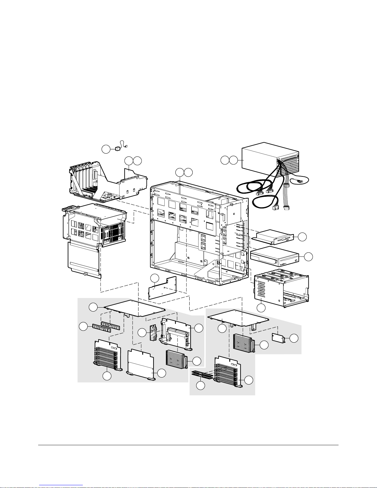
System Components Exploded View
12
22
23
1
2
10
9
29
27
1600
20
21
24
25
26
18
1200
19
30
8
17
24
16
21
28
Page 15

. . . . . . . . . . . . . . . . . . . . . . . . . . . . . . . . . .
. . . . .
1-3
Figure 1-2.
Components
Exploded View of the Compaq ProLiant 1600 and ProLiant 1200 Server System
Compaq ProLiant 1600 and ProLiant 1200 Servers Maintenance and Service Guide
Page 16

. . . . . . . . . . . . . . . . . . . . . . . . . . . . . . . . . .
. . . . .
1-4 Illustrated Parts C atalog
Spares Parts List
Table 1-1
Spares Parts List - Compaq ProLiant 1600 and ProLiant 1200 Servers
Item Description Spares Part #
CHASSIS
1 Chassis (ProLiant 1600 only) 298011-001
2 Chassis (ProLiant 1200 only) 333560-001
3 Top Cover and Left Side Access Panel 271927-001
4 Right Side Access Panel 298013-001
5 Front Bezel 298012-001
6 Front Bezel Plate (Rack-Mountable model only) 271924-001
7 Feet (Tower model only) 333575-001
8 Hot-Plug Drive Cage, 3 x 1.6-inch 250909-001
SYSTEM COMPONENTS
9 Power Supply, 280W (ProLiant 1200 only) 333594-001
10 Power Supply, 325W with Bracket (ProLiant 1600 only) 271916-001
11 Fan with bracket 281844-001
12 4.5 V Battery Replacement 160274-001
13 Power Switch and Bracket 271929-001
14 Power Supply Rear Panel (ProLiant 1600 only) 270265-001
15 Power Supply Rear Panel (ProLiant 1200 only) 333576-001
BOARDS
16 Processor with Heatsink, 233/66, 512KB (ProLiant 1200 only) 278262-001
17 Processor Board, without Processor, with Cage and Fan
(ProLiant 1200 only)
18 Processor, with Heat Sink 266/66 (ProLiant 1600 only) 333561-001
19 Processor Board, without Processor (ProLiant 1600 only) 149085-001
20 Processor Board, Dual SCSI, with Cage and Fan (ProLiant 1600
only)
21 Memory Expansion Board 270183-001
22 System I/O Board, (PCI-P6), with cage (ProLiant 1200 only) 149039-001
23 System I/O Board, (PCI-P6), with cage (ProLiant 1600 only) 333570-001
24 Processor Power Module 299306-001
25 Backplane Board, PCI, Dual SCSI 149046-001
26 Processor Terminator Board 270119-001
149088-001
149089-001
Continued
Page 17

. . . . . . . . . . . . . . . . . . . . . . . . . . . . . . . . . .
. . . . .
1-5
Spares Parts List - Co m paq Pro L ian t 1600 and ProLiant 1200 Servers
Continued
Item Description Spares Part #
27 16-MB Dual Inline Memory Module (EDO, buffered, 60-ns) 289746-001
28 32-MB Dual Inline Memory Module (EDO, buffered, 60-ns) 281857-001
29 3-Mode 1.44-MB Diskette Drive 333562-001
30 16X CD-ROM Drive 278791-001
31 Diskette Cable 271928-001 *
32 Point to Point SCSI Cable 149097-001 *
33 IDE/CD Cable 271936-001 *
34 SCSI DAT/DLT Cable 300926-001 *
35
36 Diskette/CD-ROM Power Cable 271939-001 *
37 SCSI Adapter Kit 50-to-68, Female 189638-001 *
38
39 Country Kit (ProLiant 1600 only) 333568-001 *
40 Country Kit (ProLiant 1600 Rack-Mountable model only) 333567-001 *
41 Return Kit 298017-001 *
42 Carton and Buns (International) 298017-002 *
43 Maintenance and Service Guide 298015-001 *
44 Illustrated Parts Map 298016-001 *
45 Slide Rail, 22-inch, Pair 165689-002 *
OPTIONS
46 64-MB Dual Inline Memory Module (EDO, buffered, 60-ns) 281858-001 *
47 128-MB Dual Inline Memory Module (EDO, buffered, 60-ns) 281859-001 *
48 Hot-Plug Drive Cage, 5 x 1.0-inch250911-001 *
49 Duplexed Hot-Plug Drive Cage, 4 x 1.0-inch 271932-001 *
50 Rack Conversion Kit 333574-001 *
51 Integrated Management Display 271930-001 *
52 9.1-GB Non-Hot-Pluggable Wide Ultra 1.6-inch Hard Drive199886-001 *
53 9.1-GB Hot-Pluggable Wide Ultra 1.6-inch Hard Drive 199888-001 *
54 9.1-GB Non-Hot-Pluggable Fast-SCSI-2 Hard Drive 199885-001 *
55 4.3-GB Hot-Pluggable Wide Ultra 1-inch Hard Drive 242622-001 *
56 4.3-GB Non-Hot-Pluggable Wide Ultra 1-inch Hard Drive 242606-001 *
57 4.3-GB Hot-Pluggable Fast-Wide SCSI-2 Hard Drive 199598-001 *
58 4.3-GB Non-Hot-Pluggable Fast-Wide SCSI-2 Hard Drive 199599-001 *
59 4.3-GB Hot-Pluggable Fast-SCSI-2 Hard Drive 199584-001 *
60 4.3-GB Non-Hot-Pluggable Fast-SCSI-2 Hard Drive 199585-001 *
MEMORY
MASS STORAGE DEVICES
CABLES
Parallel Cable
MISCELLANEOUS
Country Kit (ProLiant 1200 only)
271938-001 *
333569-001 *
Continued
Compaq ProLiant 1600 and ProLiant 1200 Servers Maintenance and Service Guide
Page 18

. . . . . . . . . . . . . . . . . . . . . . . . . . . . . . . . . .
. . . . .
1-6 Illustrated Parts C atalog
Spares Parts List - Co m paq Pro L ian t 1600 and ProLiant 1200 Servers
Continued
Item Description Spares Part #
OPTIONS
61 2.1-GB Hot-Pluggable Wide Ultra 1-inch Hard Drive 242603-001 *
62 2.1-GB Non-Hot-Pluggable Wide Ultra 1-inch Hard Drive 242604-001 *
63 2.1-GB Hot-Pluggable Fast-Wide SCSI-2 1-inch Hard Drive 199878-001 *
64 2.1-GB Hot-Pluggable Fast-Wide SCSI-2 Hard Drive 199643-001 *
65 2.1-GB Non-Hot-Pluggable Fast-Wide SCSI-2 Hard Drive 199644-001 *
66 2.1-GB Hot-Pluggable Fast-Wide SCSI-2 Hard Drive 199428-001 *
67 2.1-GB Non-Hot-Pluggable Fast-SCSI-2 Hard Drive 142272-001 *
68 1.05-GB Hot-Pluggable Fast-SCSI-2 Hard Drive 146717-001 *
69 1.05-GB Non-Hot-Pluggable Fast-SCSI-2 Hard Drive 146799-001 *
70 1-inch Drive Tray SCA Connector 242801-001 *
71 1-inch Drive Tray, Fast-Wide Connector 199880-001 *
72 1-inch Drive Tray, Fast-SCSI-2 Connector 242593-001 *
73 1.6-inch Drive Tray, Fast-SCSI-2 Connector 199656-001 *
* Not Shown
(continued)
Page 19

. . . . . . . . . . . . . . . . . . . . . . . . . . . . . . . . . .
. . . . .
2-1
Chapter 2
Removal and Replacement
Procedures
This chapter provides subassembly/module-level removal and replacement procedures for
the ProLiant 1600 and ProLiant 1200 Servers. After completing all necessary removal and
replacement procedures, run the Diagnostics program to verify that all components
operate properly.
To service Compaq ProLiant 1600 and ProLiant 1200 Servers, you might need
the following:
■
Torx T-15 screwdriver
■
From the Compaq SmartStart and Support Software CD:
❏
System Configuration Utility software
❏
Drive Array Advanced Diagnostics software
❏
Diagnostics software
Electrostatic Discharge Information
A discharge of static electricity can damage static-sensitive devices or microcircuitry.
Proper packaging and grounding techniques are necessary precautions to prevent damage.
To prevent electrostatic damage, observe the following precautions:
■
Transport products in static-safe containers such as conductive tubes, bags,
or boxes.
■
Keep electrostatic-sensitive parts in their containers until they arrive at static-free
stations.
■
Cover work stations with approved static-dissipating material. Provide a wrist strap
connected to the work surface and properly grounded tools and equipment.
■
Keep work area free of non-conductive materials such as ordinary plastic assembly
aids and foam packing.
■
Make sure you are always properly grounded when touching a static-sensitive
component or assembly.
■
Avoid touching pins, leads, or circuitry.
■
Always place drives PCB assembly side down.
■
Use conductive field service tools.
Compaq ProLiant 1600 and ProLiant 1200 Servers Maintenance and Service Guide
Page 20

. . . . . . . . . . . . . . . . . . . . . . . . . . . . . . . . . .
WARNING:
WARNING:
. . . . .
2-2 Removal and Replacement Procedur es
Symbols in Equipme nt
Any surface or area of the equipment
marked with these symbols indicates the presence
of a hot surface or ho t co m po nent. I f this s ur f ace
is contacted, the potential for injur y ex is ts . T o
reduce the risk of injury fro m a ho t co m po nent,
allow the surface to coo l bef o r e touching .
Any surface or area of the equipment
marked with these symbols indicates the presence
of electrical shock hazards . T he enclo s ed ar ea
contains no operator s er viceable par ts . To reduce
the risk of injury fr o m electr ical s ho ck haz ar ds , do
not open this enclosure.
WARNING: Any RJ-45 receptacle marked with
these symbols indicates a Netw ork Interface
Connection. To r educe the ris k of electrical shock,
fire, or damage to the equipment, do not plug
telephone or telecommunicatio ns co nnectors into
this receptacle.
CLASS 1 LASER PRODUCT
Preparation Procedures
Before beginning any of the removal and replacement procedures for non-hot-plug devices:
1. Turn off the server.
2. Disconnect the AC power cord from the AC outlet, then from the server.
3. Disconnect all external peripheral devices from the server.
4. For some removal and replacement procedures, you must remove the server from
the rack and place it on a sturdy table or workbench. Refer to the ProLiant 1600 and
ProLiant 1200 Servers Setup and Installation Guide for instructions.
WARNING: This label or equivalent is located on
the surface of your C D - R O M drive. This label
indicates that the product is classified as a C L AS S
1 LASER PRODUCT.
Page 21

. . . . . . . . . . . . . . . . . . . . . . . . . . . . . . . . . .
. . . . .
2-3
WARNING:
components on a vertical rather than ho r iz o ntal plane, yo u
must take precautions to pro vide f o r r ack s tability and s af ety.
It is important that you f o llo w thes e precautio ns to pr o vide
for rack stability and safety, and to protect both personnel
and property. Heed all cautions and warning s thr o ug ho ut
the installation instructions that came with the server.
CAUTION:
components. Be sure you are properly grounded before
beginning any installation procedur e. S ee the s ection titled
“Electro s t atic D is charge Information” in this chapter, f o r
more informatio n.
Because the rack allows you to st ack co m puter
Electrostatic discharge can damage electronic
Compaq ProLiant 1600 and ProLiant 1200 Servers Maintenance and Service Guide
Page 22

. . . . . . . . . . . . . . . . . . . . . . . . . . . . . . . . . .
. . . . .
2-4 Removal and Replacement Procedur es
Rack Warnings
WARNING:
To reduce the risk of personal injury, make sure
that the rack is adequately stabilized before ex tending a
component outside the rack. A rack may become unstable
if more than one com po nent is ex tended f o r any r eason.
Extend only one component at a time.
WARNING:
To reduce the risk of personal injury or damage
to the equipment, be sure that:
■ The leveling jacks are extended to the floor.
■ The full weight of the r ack r est s o n the leveling jacks .
■ The stabilizers are attached to the r ack if it is a s ing le r ack
installation.
■ The racks are coupled together in multiple rack
installations.
WARNING:
To reduce the risk of electric shock or damage
to the equipment:
■ Do not disable the power co r d g r o unding plug. The
grounding plug is an impo r tant s af ety f eature.
■ Plug the power cord into a g r o unded ( ear thed) electr ical
outlet that is easily accessible at all times .
■ Install the power supply bef o r e co nnecting the po w er
cord to the power supply.
■ Unplug the power cord befo r e rem o ving the po w er
supply from the server.
■ If the system has multiple power supplies, disconnect
power from the s y s tem by unplugging all power co rds
from the power s u pplies .
CAUTION:
The Compaq ProLiant S er ver m us t alw ays be
operated with the system unit co ver o n. Pr o per co o ling will
not be achieved if the system unit co ver is rem o ved.
Page 23

. . . . . . . . . . . . . . . . . . . . . . . . . . . . . . . . . .
. . . . .
2-5
Server Warnings and Precautions
WARNING:
surfaces, allow the inter nal s y s tem components to cool
before touching.
WARNING:
to the equipment:
■ Do not disable the power co r d g r o unding plug. The
grounding plug is an impo r tant s af ety f eature.
■ Plug the power cord into a g r o unded ( ear thed) electr ical
outlet that is easily accessible at all times .
■ Disconnect power fro m the s erv er by unplug g ing the
power cord fro m either the electr ical o utlet o r the s erv er .
CAUTION:
temporary interruptions w ith a r egu lating uninterr uptible
power supply (UPS). T his device pro t ects the har dw ar e fr o m
damage caused by power sur g es and vo ltag e s pikes and
keeps the system in operatio n dur ing a po wer failure.
CAUTION:
always be operated with the sys t em unit co ver o n. Proper
cooling will not be achieved if the s y s tem unit co ver is
removed.
To reduce the risk of personal injury from hot
To reduce the risk of electric shock or damage
Protect the server from power fluctuations and
The ProLiant 1600 and ProLiant 1200 Servers
must
Compaq ProLiant 1600 and ProLiant 1200 Servers Maintenance and Service Guide
Page 24

. . . . . . . . . . . . . . . . . . . . . . . . . . . . . . . . . .
. . . . .
2-6 Removal and Replacement Procedur es
Front Bezel
To remove the front bezel:
1. Unlock the front bezel keylock.
2. Open the front bezel.
3. Lift up the front bezel and pull it away from the chassis.
Figure 2-1.
Reverse steps 1 through 3 to replace the front bezel.
Removing the Front Bezel
Page 25

. . . . . . . . . . . . . . . . . . . . . . . . . . . . . . . . . .
. . . . .
2-7
Feet
To remove the feet from the chassis, one at a time:
1. Perform the preparation procedures. See page 2-2.
2. Remove the front bezel. See page 2-6.
3. Place the server on its left side.
4. Remove the T-15 screw from each foot ➊.
5. Pivot each foot down ➋, and pull it off the base of the chassis ➌.
3
2
1
Figure 2-2.
Reverse steps 1 through 5 to replace the feet. Make sure each foot snaps securely
in its holders.
Removing the Feet From the Chassis
Compaq ProLiant 1600 and ProLiant 1200 Servers Maintenance and Service Guide
Page 26

. . . . . . . . . . . . . . . . . . . . . . . . . . . . . . . . . .
. . . . .
2-8 Removal and Replacement Procedur es
Left Side Access Panel
Remove the top cover to service the hot-plug drive cage, CD-ROM drive, power supply,
and backplane board. To remove the left side access panel:
WARNING:
surfaces, allow the inter nal s y s tem components to cool
before touching them.
1. Perform the preparation procedures. See page 2-2.
2. Open the front bezel.
3. Loosen the two thumbscrews attaching the left side access panel to the front of
the chassis.
4. Slide the left side access panel back and pull it away from the chassis.
To reduce the risk of personal injury from hot
Figure 2-3.
Reverse steps 1 through 4 to replace the left side access panel.
Removing the Left Side Access Panel
Page 27

. . . . . . . . . . . . . . . . . . . . . . . . . . . . . . . . . .
. . . . .
2-9
Top Cover
Remove the top cover to service the PCI and EISA boards, system switches, signal cables,
I/O fan, Integrated Management Display (if installed), and the power switch.
WARNING:
surfaces, allow the inter nal s y s tem components to cool
before touching them.
To remove the top cover:
1. Perform the preparation procedures. See page 2-2.
2. Open the front bezel.
3. Loosen the thumbscrew attaching the top cover to the chassis ➊.
4. Slide the top cover back and out ➋.
5. Lift the top cover from the chassis.
To reduce the risk of personal injury from hot
2
1
Figure 2-4.
Reverse steps 1 through 5 to replace the top cover.
Removing the Top Cover
Compaq ProLiant 1600 and ProLiant 1200 Servers Maintenance and Service Guide
Page 28

. . . . . . . . . . . . . . . . . . . . . . . . . . . . . . . . . .
. . . . .
2-10 Removal and Replacement Procedur es
Right Side Access Panel
Remove the right side access panel to convert from tower to rack or to replace a damaged
panel. To remove the right side access panel from the chassis:
1. Perform the preparation procedures. See page 2-2.
2. Remove the front bezel. See page 2-6.
3. Remove the feet on the base of the right side access panel. See page 2-7.
4. Remove the two T-15 screws securing the right side access panel to the front
of the chassis.
5. Pull the right side access panel back and away from the chassis.
Figure 2-5.
Reverse steps 1 through 5 to replace the right side access panel.
Removing the Right Side Access Panel
Page 29

. . . . . . . . . . . . . . . . . . . . . . . . . . . . . . . . . .
. . . . .
2-11
Mass Storage
Compaq ProLiant 1600 and ProLiant 1200 Servers ship standard with a hot-plug drive cage
containing three 1.6-inch hot-plug drive bays. Four removable media bays contain one
third-height diskette drive and one half-height IDE CD-ROM drive. Two bays can contain a
second CD-ROM, tape drives, hard drives, or any SCSI device.
The Compaq ProLiant 1600 and ProLiant 1200 Servers support up to seven mass storage
devices. The following table and illustration describe the drive configurations.
6
6
5
5
4
4
3
3
Removable
Media
Area
Figure 2-6.
Drive
Position
0 Hot-Plug Drive Bay
1 Hot-Plug Drive Bay
2 Hot-Plug Drive Bay
3Media Slot
4Media Slot
5 CD-ROM Drive
6 Diskette Drive
Server Drive Positions
Description of Drive Bays
Hot-Pluggable
Table 2-1
Configuration
012
021
Hot-Pluggable
Hard Drive
Bays
Compaq ProLiant 1600 and ProLiant 1200 Servers Maintenance and Service Guide
Page 30

. . . . . . . . . . . . . . . . . . . . . . . . . . . . . . . . . .
. . . . .
2-12 Removal and Replacement Procedur es
Hot-Plug Drive Cage
To remove the hot-plug drive cage:
1. Perform the preparation procedures. See page 2-2.
2. Remove the front bezel. See page 2-6.
3. Remove the left side access panel. See page 2-8.
4. Disconnect all cables from the hot-plug drive cage.
5. Remove the four T-15 screws.
6. Slide the hot-plug drive cage out the front of the chassis.
Figure 2-7.
Reverse steps 1 through 6 to replace the hot-plug drive cage.
Removing the Hot-Plug Drive Cage
CAUTION:
the hot-plug drive cag e hav e been r eseat ed pr o per ly .
Make sure that all power and signal cables to
Page 31

. . . . . . . . . . . . . . . . . . . . . . . . . . . . . . . . . .
. . . . .
2-13
CD-ROM Drive
To remove the CD-ROM drive:
1. Perform the preparation procedures. See page 2-2.
2. Open the front bezel.
3. Remove the left side access panel. See page 2-8.
4. Remove the two T-15 screws and washers from the front of the drive.
5. Disconnect the CD-ROM cable.
6. Slide the CD-ROM drive out the front of the chassis.
7. Disconnect the power cable.
Figure 2-8.
Reverse steps 1 through 7 to replace the CD-ROM drive.
Removing the CD-ROM Drive
Compaq ProLiant 1600 and ProLiant 1200 Servers Maintenance and Service Guide
Page 32

. . . . . . . . . . . . . . . . . . . . . . . . . . . . . . . . . .
. . . . .
2-14 Removal and Replacement Procedur es
Diskette Drive
To remove the diskette drive:
1. Perform the preparation procedures. See page 2-2.
2. Remove the front bezel. See page 2-6.
3. Remove the top cover. See page 2-9.
4. Disconnect all cables from the diskette drive.
5. Remove the two T-15 screws and washers from the front of the drive.
6. Slide the diskette drive out the front of the chassis.
Figure 2-9.
Reverse steps 1 through 6 to replace the diskette drive.
Removing the Diskette Drive
Page 33

. . . . . . . . . . . . . . . . . . . . . . . . . . . . . . . . . .
. . . . .
2-15
Cable Diagrams
Figure 2-10.
Figure 2-11.
IDE CD-ROM Drive Cable Diagram
Diskette Drive Cable Diagram
Compaq ProLiant 1600 and ProLiant 1200 Servers Maintenance and Service Guide
Page 34

. . . . . . . . . . . . . . . . . . . . . . . . . . . . . . . . . .
. . . . .
2-16 Removal and Replacement Procedur es
Figure 2-12.
Figure 2-13.
Hot-Plug Drive Cage Cable Folding and Routing Diagram (ProLiant 1600)
Hot-Plug Drive Cage Cable Folding and Routing Diagram (ProLiant 1200)
Page 35

. . . . . . . . . . . . . . . . . . . . . . . . . . . . . . . . . .
. . . . .
2-17
System I/O Board Cage
The system I/O board cage contains the system I/O board with PCI slots, system switches,
EISA slots, and the battery. Four slots are PCI/EISA; two are PCI only, for a total of six
slots.
To remove the system I/O board cage:
1. Perform the preparation procedures. See page 2-2.
2. Remove the top cover. See page 2-9.
3. Disconnect all cables from the system I/O board cage.
4. Remove any installed boards. Place them on a non-conductive work surface. You
will install them on the replacement system I/O board cage.
5. Remove the two security screws (if installed).
6. Push down on the cage ejector lever ➊, and pull out ➋.
7. Pull the system I/O board cage out the back of the chassis ➌.
1
2
3
Figure 2-14.
Reverse steps 1 through 7 to replace the system I/O board cage. Install any boards removed
in step 4 onto the replacement system I/O board cage.
Removing the System I/O Board Cage
Compaq ProLiant 1600 and ProLiant 1200 Servers Maintenance and Service Guide
Page 36

. . . . . . . . . . . . . . . . . . . . . . . . . . . . . . . . . .
. . . . .
2-18 Removal and Replacement Procedur es
I/O Fan
To remove the I/O fan:
1. Perform the preparation procedures. See page 2-2.
2. Remove the top cover. See page 2-9.
3. Loosen the single thumbscrew attaching the I/O fan to the chassis ➊.
4. Tilt the top of the I/O fan forward and away from the chassis ➋.
5. Disconnect the I/O fan cable and slide it out of the clip ➌.
6. Lift the I/O fan away from the chassis.
1
Figure 2-15.
Reverse steps 1 through 6 to replace the I/O fan.
Removing the I/O Fan
2
3
Page 37

. . . . . . . . . . . . . . . . . . . . . . . . . . . . . . . . . .
WARNING:
. . . . .
2-19
Power Switch
To remove the power switch and cable assembly:
1. Perform the preparation procedures. See page 2-2.
Any surface or area of the equipment
marked with these symbols indicates the presence
of electrical shock hazards . T he enclo s ed ar ea
contains no operator- s er viceable par ts . To reduce
the risk of injury fr o m electr ical s ho ck haz ar ds , do
not open this enclosure.
2. Remove the front bezel. See page 2-6.
3. Remove the top cover. See page 2-9.
4. Remove the single T-15 screw ➊.
5. Slide the power switch housing back ➋ and lift it out of the chassis ➌.
Figure 2-16.
2
3
1
Removing the Power Switch Housing
Compaq ProLiant 1600 and ProLiant 1200 Servers Maintenance and Service Guide
Page 38

. . . . . . . . . . . . . . . . . . . . . . . . . . . . . . . . . .
. . . . .
2-20 Removal and Replacement Procedur es
6. Unwind the power supply cables and LED cables from the strain-relief casing and
disconnect them from the power switch.
Power
SCSI
Activity
Figure 2-17.
Reverse steps 1 through 6 to replace the power switch and cable assembly.
Disconnecting the Power Switch Cables
Page 39

. . . . . . . . . . . . . . . . . . . . . . . . . . . . . . . . . .
. . . . .
2-21
Processor Cage Assembly
The processor cage assembly contains the processor cage, processor board, Pentium II
adapter board (ProLiant 1600 only), processor, processor power module, terminator board,
memory expansion board, and memory. See Chapter 1, “Illustrated Parts Catalog,” for the
spares parts numbers for these items.
Processor Cage
To remove the processor cage:
1. Perform the preparation procedures. See page 2-2.
2. Disconnect all cables from the processor cage assembly.
3. Remove the two security screws (if installed).
4. Push down on the processor cage ejector lever ➊, and pull out ➋.
Figure 2-18.
1
2
Pulling Out the Processor Cage Lever
Compaq ProLiant 1600 and ProLiant 1200 Servers Maintenance and Service Guide
Page 40

. . . . . . . . . . . . . . . . . . . . . . . . . . . . . . . . . .
. . . . .
2-22 Removal and Replacement Procedur es
5. Pull the processor cage out through the back of the chassis.
Figure 2-19.
Reverse steps 1 through 5 to replace the processor cage.
Removing the Processor Cage
Page 41

. . . . . . . . . . . . . . . . . . . . . . . . . . . . . . . . . .
. . . . .
2-23
Pentium I I Adapter Board
The Pentium II adapter board ships standard in Compaq ProLiant 1600 only. To remove
the Pentium II adapter board:
IMPORTANT:
must be installed (Com paq Pro L iant 1600 o nly) .
1. Perform the preparation procedures. See page 2-2.
2. Remove the processor cage (see page 2-21) and open the cage door.
3. Lift up two levers on each end ➊ of the Pentium II adapter board.
4. Lift the Pentium II adapter board from the processor cage ➋.
If a single process or is installed, a terminato r bo ar d
1
1
2
Figure 2-20.
Reverse steps 1 through 4 to replace the Pentium II adapter board.
Removing the Pentium II Adapter Board
Compaq ProLiant 1600 and ProLiant 1200 Servers Maintenance and Service Guide
Page 42

. . . . . . . . . . . . . . . . . . . . . . . . . . . . . . . . . .
. . . . .
2-24 Removal and Replacement Procedur es
Terminator Board
IMPORTANT:
must be installed (Com paq Pro L iant 1600 o nly) .
To remove the terminator board from the Compaq ProLiant 1600:
1. Perform the preparation procedures. See page 2-2.
2. Remove the processor cage (see page 2-21) and open the cage door.
3. Lift up two levers on each end of the terminator board ➊.
4. Lift the terminator board from the processor cage ➋.
If a single process or is installed, a terminato r bo ar d
1
1
2
Figure 2-21.
Reverse steps 1 through 4 to replace the terminator board.
Removing the Terminator Board
Page 43

. . . . . . . . . . . . . . . . . . . . . . . . . . . . . . . . . .
. . . . .
2-25
Processors
Compaq ProLiant 1600
To remove the Compaq ProLiant 1600 processor:
IMPORTANT:
must be installed (Com paq Pro L iant 1600 o nly) .
1. Perform the preparation procedures. See page 2-2.
2. Remove the processor cage (see page 2-21) and open the cage door.
3. Remove the Pentium II adapter board and place it on a non-conductive work
surface. See page 2-23.
4. Push in the latches on each side of the processor until you hear two clicks ➊. This
locks the tabs in the open position.
5. Slide the processor from the Pentium II adapter board ➋.
If a single process or is installed, a terminato r bo ar d
Figure 2-22.
Reverse steps 1 through 5 to replace the Compaq ProLiant 1600 processor.
Removing the Processor from the Compaq ProLiant 1600 Server
1
2
Compaq ProLiant 1600 and ProLiant 1200 Servers Maintenance and Service Guide
1
Page 44

. . . . . . . . . . . . . . . . . . . . . . . . . . . . . . . . . .
. . . . .
2-26 Removal and Replacement Procedur es
Compaq ProLiant 1200
To remove the Compaq ProLiant 1200 processor:
1. Perform the preparation procedures. See page 2-2.
2. Remove the processor cage (see page 2-21) and open the cage door.
3. Push in the latches on each side of the processor until you hear two clicks ➊. This
locks the tabs in the open position.
4. Lift the processor from the processor board ➋.
1
1
1
Figure 2-23.
Reverse steps 1 through 4 to replace the Compaq ProLiant 1200 processor.
Removing the Processor from the Compaq ProLiant 1200 Server
2
Page 45

. . . . . . . . . . . . . . . . . . . . . . . . . . . . . . . . . .
. . . . .
2-27
Processor Power Module
Compaq ProLiant 1600
To remove the processor power module from a Compaq ProLiant 1600 Server:
1. Perform the preparation procedures. See page 2-2.
2. Remove the processor cage (see page 2-21) and open the cage door.
3. Remove the Pentium II adapter board and place it on a non-conductive work
surface. See page 2-23.
4. Pull out the clips on each end of the processor power module ➊.
5. Slide the processor power module from the Pentium II adapter board ➋.
1
2
Figure 2-24.
Reverse steps 1 through 5 to replace a processor power module in the Compaq ProL iant
1600 Server. The clips on the processor power module will snap into a locked position
automatically when the processor power module is pushed into the slot.
Removing the Processor Power Module from the Compaq ProLiant 1600
Server
Compaq ProLiant 1600 and ProLiant 1200 Servers Maintenance and Service Guide
Page 46

. . . . . . . . . . . . . . . . . . . . . . . . . . . . . . . . . .
. . . . .
2-28 Removal and Replacement Procedur es
Compaq ProLiant 1200
To remove a processor power module from a Compaq ProLiant 1200 Server:
1. Perform the preparation procedures. See page 2-2.
2. Remove the processor cage (see page 2-21) and open the cage door.
3. Remove the processor. See page 2-26.
4. Pull out the clips on each end of the processor power module ➊.
5. Lift the processor power module from the processor board ➋.
1
Figure 2-25.
Reverse steps 1 through 5 to replace a processor power module in the Compaq ProL iant
1200 Server. The clips on the processor power module will snap into a locked position
automatically when the processor power module is pushed into the slot.
Removing the Processor Power Module from the Compaq ProLiant 1200
Server
2
Page 47

. . . . . . . . . . . . . . . . . . . . . . . . . . . . . . . . . .
. . . . .
2-29
Memory Expansion Board
To remove the memory expansion board:
1. Perform the preparation procedures. See page 2-2.
2. Remove the processor cage. See page 2-21.
3. Lift up the locking levers on each side of the memory board ➊.
4. Lift up the memory expansion board to unplug it from the processor board slot ➋.
1
2
Figure 2-26.
Reverse steps 1 through 4 to replace the memory expansion board.
Removing the Memory Expansion Board
Compaq ProLiant 1600 and ProLiant 1200 Servers Maintenance and Service Guide
Page 48

. . . . . . . . . . . . . . . . . . . . . . . . . . . . . . . . . .
. . . . .
2-30 Removal and Replacement Procedur es
Memory
Compaq ProLiant 1600 Servers ship standard with 64 megabytes of memory (two 32-MB
DIMMs) installed on the processor board. Memory is expandable to 512 megabytes.
Compaq ProLiant 1200 Servers ship standard with 32 megabytes of memory (two 16-MB
DIMMs) installed on the memory board. Memory is expandable to 512 megabytes.
Figure 2-27.
J12
J11
J10
J9
J8
J7
J6
J5
Figure 2-28.
J4
J3
J2
J1
DIMM Sockets on the Processor Board (Compaq ProLiant 1600 only)
Bank 6
Bank 6
Bank 5
Bank 5
Bank 4
Bank 4
Bank 3
Bank 3
Note: Both slots in a bank must be populated.
DIMM Sockets on the Memory Expansion Board
Page 49

. . . . . . . . . . . . . . . . . . . . . . . . . . . . . . . . . .
. . . . .
2-31
The following guidelines MUST be followed when installing or replacing memory:
■
Use 60-ns or faster; 16-, 32-, 64-, or 128-MB; EDO 4-K refresh DIMMs.
■
DIMMs must be installed in matched pairs that are identical in size and speed.
However, each pair of DIMMs need not be of the same size. For example, two
16-MB DIMMs can be installed in sockets 1 and 2, and two 32-MB DIMMs can be
installed in sockets 3 and 4.
■
To optimize system performance, fill the DIMM sockets in the following order,
keeping in mind that some sockets may already be filled or are not included in your
model:
❏
Bank 1: DIMM sockets 1 and 2 on the processor board (ProLiant 1600 only)
❏
Bank 3: DIMM sockets 5 and 6 on the memory expansion board
❏
Bank 2: DIMM sockets 3 and 4 on the processor board (ProLiant 1600 only)
❏
Bank 4: DIMM sockets 7 and 8 on the memory expansion board
❏
Bank 5: DIMM sockets 9 and 10 on the memory expansion board
❏
Bank 6: DIMM sockets 11 and 12 on the memory expansion board
CAUTION:
Use only Compaq DIMMs. DIMMs from other
sources may adversely affect data integrity. Power-On SelfTest (POST) w ill warn of non-s upported DIMMs.
To remove a DIMM:
1. Perform the preparation procedures. See page 2-2.
2. Remove the processor cage and place it on a non-conductive work surface. See page
2-21. Open the cage door.
3. Locate the appropriate DIMM socket on the processor board or the memory
expansion board. If necessary, remove the memory expansion board and place it on
a non-conductive work surface. See page 2-29.
Compaq ProLiant 1600 and ProLiant 1200 Servers Maintenance and Service Guide
Page 50

. . . . . . . . . . . . . . . . . . . . . . . . . . . . . . . . . .
. . . . .
2-32 Removal and Replacement Procedur es
4. Push the levers on each end of the memory module ➊.
5. Pull the module from the board ➋.
Figure 2-29.
1
Removing a DIMM from the Processor Board (ProLiant 1600 only)
1
2
1
2
1
Figure 2-30.
Removing a DIMM from the Memory Expansion Board
Reverse steps 1 through 5 to replace the DIMM. The DIMM can be installed in only one
way. Match the notch on the module with the tab on the memory socket. Push the module
down into the socket, making sure that the module is fully inserted and properly seated.
Page 51

. . . . . . . . . . . . . . . . . . . . . . . . . . . . . . . . . .
. . . . .
2-33
The following tables show possible memory upgrade configurations for Compaq ProLiant
1600 and 1200 Servers.
Table 2-2
Examples of DIMM Upgrade Combinations -
Compaq ProLiant 1600
Total
Memory
64 MB 2 x 32 MB
128 MB 2 x 32 MB 2 x 32 MB
256 MB 2 x 32 MB 2 x 32 MB 2 x 32 MB 2 x 32 MB
256 MB 2 x 32 MB 2 x 64 MB 2 x 32 MB
256 MB 2 x 32 MB 2 x 16 MB 2 x 32 MB 2 x 16 MB 2 x 16 MB 2 x 16 MB
512 MB 2 x 128 MB 2 x 128 MB
512 MB 2 x 32 MB 2 x 64 MB 2 x 64 MB 2 x 32 MB 2 x 32 MB 2 x 32 MB
Bank 1 Bank 2 Bank 3 Bank 4 Bank 5 Bank 6
Table 2-3
Examples of DIMM Upgrade Combinations -
Compaq ProLiant 1200
Total Memory Bank 1 Bank 2 Bank 3 Bank 4
32 MB 2 x 16 MB
64 MB 2 x 16 MB 2 x 16 MB
64 MB 2 x 32 MB
128 MB 2 x 16 MB 2 x 16 MB 2 x 16 MB 2 x 16 MB
128 MB 2 x 32 MB 2 x 32 MB
128 MB 2 x 64 MB
128 MB 2 x 16 MB 2 x 16 MB 2 x 32 MB
256MB 2 x 16 MB 2 x 16 MB 2 x 32 MB 2 x 64 MB
256 MB 2 x 32 MB 2 x 32 MB 2 x 32 MB 2 x 32 MB
256 MB 2 x 32 MB 2 x 32 MB 2 x 64 MB
256 MB 2 x 64 MB 2 x 64 MB
256 MB 2 x 128 MB
512 MB 2 x 64 MB 2 x 64 MB 2 x 64 MB 2 x 64 MB
512 MB 2 x 64 MB 2 x 64 MB 2 x 128 MB
512 MB 2 x 128 MB 2 x 128 MB
Compaq ProLiant 1600 and ProLiant 1200 Servers Maintenance and Service Guide
Page 52

. . . . . . . . . . . . . . . . . . . . . . . . . . . . . . . . . .
. . . . .
2-34 Removal and Replacement Procedur es
Power Supply
To remove the power supply:
1. Perform the preparation procedures. See page 2-2.
2. Remove the left side access panel. See page 2-8.
3. Remove the processor cage. See page 2-21.
4. (Compaq ProLiant 1600 only) Slide the hot-plug drive cage out slightly ➊.
5. (Compaq ProLiant 1600 only) Remove the processor baffle by detaching the velcro
holding it to the power supply.
6. (Compaq ProLiant 1600 only) Disconnect the power supply cable from the power
switch.
7. Disconnect all other power supply cables.
8. Remove four T-15 screws securing the power supply to the back of the chassis ➋.
9. Pull the power supply out the side of the chassis ➌.
3
2
Figure 2-31.
Reverse steps 1 through 9 to replace the power supply.
Removing the Power Supply
1
Page 53

. . . . . . . . . . . . . . . . . . . . . . . . . . . . . . . . . .
. . . . .
2-35
Backplane Board
The Compaq ProLiant 1600 backplane board has two SCSI connectors. The Compaq
ProLiant 1200 backplane board has one SCSI connector
To remove the backplane board:
1. Perform the preparation procedures. See page 2-2.
2. Remove the top cover. See page 2-9.
3. Remove the left side access panel. See page 2-8.
4. Remove the system I/O board cage. See page 2-17.
5. Remove the processor cage. See page 2-21.
6. Disconnect all cables from the backplane board.
7. Remove the three T-15 screws from the backplane board.
8. Slide the backplane board down slightly and pull it from its mounting posts.
Figure 2-32.
Reverse steps 1 through 8 to replace the backplane board.
Removing the Backplane Board
Compaq ProLiant 1600 and ProLiant 1200 Servers Maintenance and Service Guide
Page 54

. . . . . . . . . . . . . . . . . . . . . . . . . . . . . . . . . .
. . . . .
2-36 Removal and Replacement Procedur es
External Replacement Battery
CAUTION:
system I/O board or permanent damage may occur. If the
battery fails, use the extern al replacem ent batter y.
To install the external replacement battery:
1. Perform the preparation procedures. See page 2-2.
2. Remove the top cover. See page 2-9.
3. Connect the replacement battery to the battery header on the system I/O board.
4. Move the jumper on connector E2 from pins 1 and 2 to pins 2 and 3.
Do not remove the lithium battery from the
Figure 2-33.
5. Remove the adhesive backing from the hook-and-loop fastener strip. Place the
battery and the hook-and-loop fastener strip as indicated in the following illustration.
6. Place the sticker included with your battery kit on the back of your server above the
power connector.
7. Run the System Configuration utility to reconfigure the server.
Installing the External Replacement Battery
Page 55

. . . . . . . . . . . . . . . . . . . . . . . . . . . . . . . . . .
. . . . .
3-1
Chapter 3
Diagnostic Tools
This chapter describes software and firmware diagnostic tools available for Compaq server
products. The sections in this chapter are:
■
Utility Access
■
Power-On Self-Test (POST)
■
Diagnostics Software
■
Drive Array Advanced Diagnostics (DAAD)
■
Integrated Management Log
■
Rapid Recovery Services
■
Remote Service Features
■
ROMPaq
■
Compaq Insight Manager
Compaq ProLiant 1600 and ProLiant 1200 Servers Maintenance and Service Guide
Page 56

. . . . . . . . . . . . . . . . . . . . . . . . . . . . . . . . . .
. . . . .
3-2 Diagnostic Tools
Utility Access
The Compaq SmartStart and Support Software CD contains the SmartStart program and
many of the Compaq utilities needed to maintain your system, including:
■
System Configuration Utility
■
Array Configuration Utility
■
Drive Array Advanced Diagnostics Utility
■
ROMPaq Firmware Upgrade Utilities
CAUTION: Do not select the Erase Utility when running the
SmartStart and Support So ftware CD. This w ill r esult in data
loss to the entire system.
There are several ways to access these utilities:
■
Run the Utilities on the system partition.
If the system was installed using SmartStart, the Compaq utilities are automatically
available on the system partition. The system partition could also have been created
during a manual system installation.
To run the utilities on the system partition, boot the system and press F10 when you
see the following message: “Press F10 for system partition utilities.” Then select the
utilities from the menu.
❏
System Configuration Utility is available under System Configuration menu.
❏
Array Configuration Utility is available under the System Configuration menu.
❏
Drive Array Advanced Diagnostics Utility is available under the Diagnostics
and Utilities menu.
❏
ROMPaq Firmware Upgrade Utility is available under the Diagnostics and
Utilities menu.
Page 57

. . . . . . . . . . . . . . . . . . . . . . . . . . . . . . . . . .
IMPORTANT:
. . . . .
3-3
■
Run the Utilities from diskette.
You can run the utilities from their individual diskettes. If you have a utility diskette
newer than the version on the SmartStart and Support Software CD, use that
diskette.
You can also create a diskette version of the utility from the SmartStart and Support
Software CD. To create diskette versions of the utilities from the CD:
1. Boot the Compaq SmartStart and Support Software CD.
2. From the Compaq System Utilities screen, select Create Support Software and
select Next.
3. Select the diskette you would like to create from the list and follow the
instructions on the screen.
■
Run the Utilities from the Compaq SmartStart and Support Software CD.
Only the System Co nf ig ur atio n U tility and the Ar r ay
Configuration U tility can be ex ecuted f r o m the Compaq
SmartStart and Support So ftware CD. All other utilities can be
executed only from the system partit io n o r from diskette.
To run these utilities directly from the Compaq SmartStart and Support Software CD:
1. Boot the Compaq SmartStart and Support Software CD.
2. From the Compaq System Utilities screen, select the utility you wish to run and
select Next.
❏
To execute the System Configuration Utility, select Run System
Configuration Utility.
❏
To execute the Array Configuration Utility, select Run Array
Configuration Utility.
Compaq ProLiant 1600 and ProLiant 1200 Servers Maintenance and Service Guide
Page 58

. . . . . . . . . . . . . . . . . . . . . . . . . . . . . . . . . .
. . . . .
3-4 Diagnostic Tools
Power-On Self-Test (POST)
POST is a series of diagnostic tests that runs automatically on Compaq computers when the
system is turned on. POST checks the following assemblies to ensure that the computer
system is functioning properly:
■
Keyboard
■
Power supply
■
System board
■
Memory
■
Memory expansion boards
■
Controllers
■
Diskette drives
■
Hard drives
If POST finds an error in the system, an error condition is indicated by an audible and/or
visual message. If an error code is displayed on the screen during POST or after resetting
the system, follow the instructions in Table 3-1. The error messages and codes listed in
Table 3-1 include all codes generated by Compaq products. Your system generates only
those codes that are applicable to your configuration and options.
Table 3-1
POST Error Messages
Audible
Beeps
Error Code
A Critical Error
occurred prior
to this powerup
101-ROM Error 1L,1S System ROM
101-I/O ROM
Error
102-System
Board Failure
L=Long
S=Short
None A catastrophic system
None Options ROM
None DMA, timers, etc. Replace the system
Probable Source of
Problem Action
error, which caused
the server to crash,
has been logged.
checksum.
checksum.
Run Diagnostics.
Replace failed
assembly as indicated.
Run Diagnostics.
Replace failed
assembly as indicated.
Run Diagnostics.
Replace failed
assembly as indicated.
board. Run the
Compaq System
Configuration Utility.
Page 59

. . . . . . . . . . . . . . . . . . . . . . . . . . . . . . . . . .
. . . . .
3-5
104-ASR-2
Timer Failure
162-System
Options Not
Set
None System bo ard failure. Run Diagnostics.
Replace failed
assembly as indicated.
2S Configuration
incorrect.
Run the System
Configuration Utility and
correct.
Continued
Compaq ProLiant 1600 and ProLiant 1200 Servers Maintenance and Service Guide
Page 60

. . . . . . . . . . . . . . . . . . . . . . . . . . . . . . . . . .
. . . . .
3-6 Diagnostic Tools
POST Error Messages
Audible
Error Code
163-Time &
Date Not Set
164-Memory
Size Error
170- Expansion
Device Not
Responding
172Configuration
Nonvolatile
Memory
Invalid
172-1
Configuration
Nonvolatile
Memory
Invalid
173- Slot ID
Mismatch
174Configuration/
Slot Mismatch
Device Not
Found
175Configuration/
Slot Mismatch
Device Foun d
176-Slot with
Not Readable
ID Yields
Valid ID
177Configuration
Not Complete
L=Long
S=Short
2S Invalid time or date in
2S Configuration
None EISA or PCI expansion
None Nonvolatile
None Nonvolatile
None Board replaced,
None EISA or PCI board not
None EISA or PCI board
None EISA or PCI board in
None Incomplete System
Continued
Beeps
Probable Source of
Problem Action
configuration
memory.
memory incorrect.
board failure.
configuration corrupt
or jumper installed.
configuration corrupt.
configuration not
updated.
found.
added, configuration
not updated.
slot that should
contain an ISA board.
Configuration.
Run the System
Configuration Utility and
correct.
Run the System
Configuration Utility and
correct.
Check board for secure
installation. Replace
the failed board if
necessary.
Run the System
Configuration Utility and
correct.
Run the System
Configuration Utility and
correct.
Run the System
Configuration Utility and
correct.
Run the System
Configuration Utility and
correct.
Run the System
Configuration Utility and
correct.
Run the System
Configuration Utility and
correct.
Run the System
Configuration Utility and
correct.
Page 61

. . . . . . . . . . . . . . . . . . . . . . . . . . . . . . . . . .
. . . . .
3-7
178-Processor
Configuration
Invalid
179-System
Revision
Mismatch
180-Log
Reinitialized
201-Memory
Error
None Proce ssor type or step
does not match
configuration
memory.
None A board was installed
that has a different
revision date.
None
None RAM failure. Run Diagnostics.
Run the System
Configuration Utility and
correct.
Run the System
Configuration Utility and
correct.
Replace failed
assembly as indicated.
Continued
Compaq ProLiant 1600 and ProLiant 1200 Servers Maintenance and Service Guide
Page 62

. . . . . . . . . . . . . . . . . . . . . . . . . . . . . . . . . .
. . . . .
3-8 Diagnostic Tools
POST Error Messages
Audible
Error Code
203-Memory
Address Error
205-Cache
Memory Error
205-Option
Cache
Memory Error
206-Cache
Controller Error
207-Invalid
Memory
Configuration Check DIMM
[SIMM]
Installation
208-Invalid
Memory
Speed - Check
DIMM [SIMM]
Installation
211-Cache
Switch Set
Incorrectly
212-System
Processor
Failed/Mappe
d out
213-Cache
Size Error
L=Long
S=Short
None RAM failure. Run Diagnostics.
None Cache memory error. Replace the processor
None Option cache
None Cache controller
None Memory module
1L, 1S The speed of the
None Switch not set
1S Processor in slot x
None Invalid optional
Continued
Beeps
Probable Source of
Problem Action
memory error.
failure.
installed incorrectly.
memory is too slow,
where:
xx00 = expansion
board SIMMs are too
slow, or
00yy = syste m board
SIMMs are too slow.
xx and yy have
correspon ding bit set.
properly during
installation or
upgrade.
failed.
cache size.
Replace failed
assembly as indicated.
board in the slot
indicated.
Replace the option
cache board.
Run Diagnostics.
Replace failed
assembly as indicated.
Verify placement of
memory modules.
The speed of the
memory modules must
be 60 ns. Verify the
speed of the memory
modules installed and
replace.
Verify switch setti ngs.
Run Diagnostics and
replace failed
processor.
Replace cache with
256K cache.
Page 63

. . . . . . . . . . . . . . . . . . . . . . . . . . . . . . . . . .
. . . . .
3-9
213-System
Processor Not
Installed
214-DC-DC
Converter
Failed
301-Keyboard
Error
301-Keyboard
Error or Test
Fixture Installed
1S System processor
configured for slot
indicated is missing.
None PowerSafe Module
(DC-DC Converter)
failed.
None Keyboard failure. Turn off the computer,
None Keyboard failure. Replace the keyboard.
Install processor in the
slot indicated or run the
System Configuration
Utility to remove the
processor from the
CFG
.
file.
Run Diagnostics.
Replace failed
assembly as indicated.
then reconnect the
keyboard.
Continued
Compaq ProLiant 1600 and ProLiant 1200 Servers Maintenance and Service Guide
Page 64

. . . . . . . . . . . . . . . . . . . . . . . . . . . . . . . . . .
. . . . .
3-10 Diagnostic Tools
POST Error Messages
Audible
Error Code
ZZ
-301-
Keyboard Error
303-Keyboard
Controller Error
304-Keyboard
or System Unit
Error
40X-Parallel
Port X Address
Assignment
Conflict
402Monochrome
Adapter
Failure
501-Display
Adapter
Failure
601-Diskette
Controller Error
605-Diskette
Drive
Type Error
L=Long
S=Short
None Keyboard failure. (
None System board,
None Keyboard, keyboard
2S Both external and
1L, 2S Monochrome display
1L, 2S Video display
None Diskette controller
2S Mismatch in drive
Continued
Beeps
Probable Source of
Problem Action
represents the
Keyboard Scan
Code.)
keyboard, or mouse
controller failure.
cable, or syst em
board failure.
internal ports are
assigned to parallel
port X.
controller.
controller.
circuitry failure.
type.
ZZ
1. A key is stuck. Try to
free it.
2. Replace the
keyboard.
1. Run Diagnostics.
2. Replace failed
assembly as
indicated.
1. Make sure the
keyboard is
attached.
2. Run Diagnostics to
determine which is in
error.
3. Replace the part
indicated.
Run the System
Configuration Utility and
correct.
Replace the
monochrome display
controller.
Replace the video
board.
1. Make sure the
diskette drive cables
are attached.
2. Replace the diskette
drive and/or cable.
3. Replace the system
board.
Run the System
Configuration Utility to
set diskette type
correctly.
Page 65

. . . . . . . . . . . . . . . . . . . . . . . . . . . . . . . . . .
. . . . .
3-11
702-A
coprocessor
has been
detected that
was not
reported by
CMOS
703-CMOS
reports a
coprocessor
that has not
been
detected
None Installed coprocessor
not configured.
2S Coprocessor or
configuration error.
Run the System
Configuration Utility and
correct.
1. Run the System
Configuration Utility
and correct.
2. Replace the
coprocessor.
Continued
Compaq ProLiant 1600 and ProLiant 1200 Servers Maintenance and Service Guide
Page 66

. . . . . . . . . . . . . . . . . . . . . . . . . . . . . . . . . .
. . . . .
3-12 Diagnostic Tools
POST Error Messages
Audible
Error Code
1151-Com Port
1 Address
Assignment
Conflict
1152-Com Port
2, 3, or 4
Address
Assignment
Conflict
1600-Server
Manager/R
Failure
1610Temperature
violation
detected.
Waiting for
system
to cool
1611-Fan
failure
detected
1612-Primary
power supply
failure
1613-Low
System Battery
1614Redundant fan
failure
detected
1701-SCSI
Controller
failure
L=Long
S=Short
2S Both external and
2S Both external and
None Server Manager/R
2S Ambient system
2S Required fan not
2S Primary power supply
None Real time cl ock
None
None A test on the Fast
Continued
Beeps
Probable Source of
Problem Action
internal serial ports
are assigned to
COM1.
internal serial ports
are assigned to
COM2, COM3 or
COM4.
board failure. Error
code displays after
error message.
temperature too hot.
installed or spinning.
has failed.
system battery is
running low on
power.
SCSI-2 Controller
failed.
Run the System
Configuration Utility and
correct.
Run the System
Configuration Utility and
correct.
Run Diagnostics.
Replace failed
assembly as indicated.
Check fan in system
environment.
Check fans.
Replace power supply
as soon as possible.
Run Diagnostics.
Replace failed
assembly as indicated.
Run Diagnostics.
Replace failed
assembly as indicated.
Page 67

. . . . . . . . . . . . . . . . . . . . . . . . . . . . . . . . . .
. . . . .
3-13
1702-SCSI
cable error
detected.
System halted.
None Incorrect cabling. 1. For integrated SCSI
Controllers, ensure
that the internal
connector has SCSI
termination
attached.
2. For option card SCSI
controllers, ensure
that only one of the
two internal
connectors has
termination
attached.
Continued
Compaq ProLiant 1600 and ProLiant 1200 Servers Maintenance and Service Guide
Page 68

. . . . . . . . . . . . . . . . . . . . . . . . . . . . . . . . . .
. . . . .
3-14 Diagnostic Tools
POST Error Messages
Audible
Error Code
1703-SCSI
cable error
detected.
Internal SCSI
cable not
attached to
system board
connector.
System halted.
1704Unsupported
Virtual Mode
Disk Operation.
DOS Driver
Required.
System halted.
1705-Locked
SCSI Bus
Detected.
System halted.
1730-Fixed Disk
0 does not
support DMA
Mode.
1731-Fixed Disk
1 does not
support DMA
Mode.
1740-Fixed Disk
0 failed Set
Block Mode
command
1741-Fixed Disk
1 failed Set
Block Mode
command
L=Long
S=Short
None Incorrect cabling. Ensure that the
None System attempted to
None SCSI bus failure. Run Diagnost ics.
None Fixed disk drive error. Run the System
None Fixed disk drive error. Run the System
None Fixed disk drive error. Run the System
None Fixed disk drive error. Run the System
Continued
Beeps
Probable Source of
Problem Action
perform a virtual
mode disk operation
without virtual mode
memory services.
integrated SCSI
controller has SCSI
termination attached.
Use fixed-disk device
driver that supports
virtual mode memory
services.
Replace failed
assembly as indicated.
Configuration Utility and
correct.
Configuration Utility and
correct.
Configuration Utility and
correct.
Configuration Utility and
correct.
Page 69

. . . . . . . . . . . . . . . . . . . . . . . . . . . . . . . . . .
. . . . .
3-15
1750-Fixed Disk
0 failed
Identify
command
1751-Fixed Disk
1 failed
Identify
command
1760-Fixed Disk
0 does not
support Block
Mode
1761-Fixed Disk
1 does not
support Block
Mode
None Fixed disk drive error. Run the System
Configuration Utility and
correct.
None Fixed disk drive error. Run the System
Configuration Utility and
correct.
None Fixed disk drive error. Run the System
Configuration Utility and
correct.
None Fixed disk drive error. Run the System
Configuration Utility and
correct.
Continued
Compaq ProLiant 1600 and ProLiant 1200 Servers Maintenance and Service Guide
Page 70

. . . . . . . . . . . . . . . . . . . . . . . . . . . . . . . . . .
. . . . .
3-16 Diagnostic Tools
POST Error Messages
Error Code
1764-Slot x Drive Array - Capacity Expansion Process is
temporarily disabled (followed by one of the following):
Expansion will resume when Array Accelerator has been
reattached.
Expansion will resume when Array Accelerator has been
replaced.
Expansion will resume when Array Accelerator RAM
allocation i s successful.
Expansion will resume when Array Accelerator battery
reaches full charge.
Expansion will resume when automatic data recovery
has been completed.
1765-Slot x Drive Array Option ROM Appears to Conflict
With an ISA Card. ISA cards with 16-bit memory cannot
be configured in memory range C0000 to DFFFF along
with the SMART-2/E 8-bit Option ROM due to EISA bus
limitations. Please remove or reconfigure your ISA card.
1766-Slot x Drive Array requires System ROM Upgrade.
Run Systems ROMPaq Utility.
1767-Slot x Drive Array Option ROM is Not Programmed
Correctly or may Conflict with the Memory Address
Range of an ISA Card. Check the Memory Address
Configuration of installed ISA Card(s) or run Options
ROMPaq Utility to attempt SMART-2/E Option ROM
Reprogramming.
1768-Slot x
Drive Array Resuming
logical drive
expansion
process.
Continued
Audible
Beeps
L=Long
S=Short
None SMART-2 Controller
Probable Source of
Problem Action
error.
Reattach or re place
Array Accelerator, wait
until the Array
Accelerator batteries
have charged, or for
Automatic Data
Recovery to complete,
as indicated.
Remove or reconfigure
conflicting ISA cards.
Disable “shared
memory” on any ISA
network cards that may
be installed.
Run the latest Systems
ROMPaq Utility to
upgrade your System
ROMs.
Remove or reconfigure
conflicting ISA cards,
especially any cards
that are not recognized
by the System
Configuration Utility. Try
reprogramming the
SMART-2/E Controller’s
ROMs using the latest
Options ROMPaq
(version 2.29 or higher).
No action required.
Appears whenever a
controller reset or
power cycle occurs
while array expansion is
in progress.
Page 71

. . . . . . . . . . . . . . . . . . . . . . . . . . . . . . . . . .
. . . . .
3-17
Continued
Compaq ProLiant 1600 and ProLiant 1200 Servers Maintenance and Service Guide
Page 72

. . . . . . . . . . . . . . . . . . . . . . . . . . . . . . . . . .
. . . . .
3-18 Diagnostic Tools
POST Error Messages
Audible
Error Code
1769-Slot x
Drive Array Drive(s)
disabled due
to failure
during
expand. Select
to continue
F1
with logical
drives
disabled.
Select
accept data
loss and to reenable logical
drives.
1771-Primary
Disk Port
Address
Assignment
Conflict
1772Secondary Disk
Port Address
Assignment
Conflict
1773-Primary
Fixed Disk Port
Assignment
Conflict
F2
to
L=Long
S=Short
None SMART-2 Controller
None Internal and external
None Address Assignment
None Fixed disk drive error. Run the System
Continued
Beeps
Probable Source of
Problem Action
error.
hard drive controllers
are both assigned to
the primary address.
Conflict. Internal and
external hard drive
controllers are both
assigned to the
secondary address.
Data has been lost
while expanding the
array, therefore the
drives have been
temporarily disabled.
Press F2 to accept the
data loss and re-en able
the logical drives.
Restore data from
backup.
Run the System
Configuration Utility and
correct.
Run the System
Configuration Utility and
correct.
Configuration Utility and
correct.
Page 73

. . . . . . . . . . . . . . . . . . . . . . . . . . . . . . . . . .
. . . . .
3-19
1774-Slot x
Drive Array Obsolete data
found in Array
Accelerator.
Select F1 to
discard
contents of
Array
Accelerator.
Select
write contents
of Array
Accelerator to
drives.
1776-Drive
Array - SCSI
Port
Termination
Error
F2
to
None SMART-2 Controller
error
None External and internal
SCSI drives are both
configured to Port 1.
Data found in Array
Accelerator is older
than data found on
drives. Press F1 to
discard the older data
in the Array Accelerator
and retain the newer
data on the drives.
Reconfigure drives.
Continued
Compaq ProLiant 1600 and ProLiant 1200 Servers Maintenance and Service Guide
Page 74

. . . . . . . . . . . . . . . . . . . . . . . . . . . . . . . . . .
. . . . .
3-20 Diagnostic Tools
POST Error Messages
Audible
Error Code
1777-Drive
Array External
Drive
Subsystem Error
1778-Drive
Array resuming
Automatic
Data Recovery
process
1779-Drive
Array
Controller
detects
replacement
drives
1780-Disk 0
Failure
1781-Disk 1
Failure
1782-Disk
Controller
Failure
1784-Drive
Array Drive
Failure,
Physical Drive
1785-Drive
Array not
Configured
L=Long
S=Short
None Cooling fan failure,
None This message appears
None Intermittent drive
None Hard drive/format
None Hard drive/format
None Hard disk drive
None Defective drive
None Configuration error. Run the System
Continued
Beeps
Probable Source of
Problem Action
internal temperature
alert or open side
panel.
whenever a controller
reset or power cycle
occurs while
Automatic Data
Recovery is in
progress.
failure and/or possible
loss of data.
error.
error.
circuitry error.
and/or cables.
Inspect for cooling fan
failure or open side
panel.
No action necessary.
If this message appears
and drive X has not
been replaced, this
indicates an
intermittent drive failure.
This message also
appears once
immediately following
drive replacement
whenever data must be
restored from backup.
Run Diagnostics.
Replace failed
assembly as indicated.
Run Diagnostics.
Replace failed
assembly as indicated.
Run Diagnostics.
Replace failed
assembly as indicated.
Check for loose cables.
Replace defective drive
X
and/or cable(s).
Configuration Utility and
correct.
Continued
Page 75

. . . . . . . . . . . . . . . . . . . . . . . . . . . . . . . . . .
. . . . .
3-21
POST Error Messages
Error Code
1786-Drive Array
Recovery
Needed
The following
drive(s) need
Automatic Data
Recovery: Drive X.
Select "F1" to
continue with
recovery of data
to drive(s).
Select "F2" to
continue without
recovery of data
to drive(s).
1787-Drive Array
Operating in
Interim Recovery
Mode.
Physical drive
replacement
needed: Drive
*1788-Incorrect
Drive Replaced:
Drive X Drive(s)
were incorrectly
replaced: Drive
Select "F1" to
continue - drive
array will remain
disabled.
Select "F2" to reset
configuration - all
data will be lost.
None Interim Data
None Hard drive X failed or
X
None Drives are not
Y
Continued
Audible
Beeps
L=Long
S=Short
Probable Source of
Problem Action
Press F1 key to allow
Recovery
mode. Data has not
been recovered yet.
cable is loose or
defective. Following
a system restart, this
message reminds
you that drive X is
defective and fault
tolerance is being
used.
installed in their
original p ositions, so
the drives have
been disabled.
note below.
See
Automatic Data
Recovery to begin.
Data will automatically
be restored to drive
now that the drive has
been replaced or now
seems to be working.
-Or-
Press the F2 key and
the system will
continue to operate in
the Interim Data
Recovery mode.
1. Replace drive X as
2. Check loose cables.
3. Replace defective
Reinstall the drives
correctly as indicated.
Press F1 to restart the
computer with the
drive array disabled.
-Or-
Press F2 to use the
drives as configured
and lose all the data
on them.
X
soon as possibl e.
cables.
Compaq ProLiant 1600 and ProLiant 1200 Servers Maintenance and Service Guide
Page 76

. . . . . . . . . . . . . . . . . . . . . . . . . . . . . . . . . .
. . . . .
3-22 Diagnostic Tools
: The 1788 error message might also be displayed inadvertently due to a bad
*NOTE
power cable connection to the drive or by noise on the data cable. If this
message was due to a bad power cable connection, but not because of an
incorrect drive replacement, repair the connection and press F2.
-OrIf this message was not due to a bad power cable connection, and no drive
replacement took place, this could indicate noise on the data cable. Check
cable for proper routing.
Continued
Page 77

. . . . . . . . . . . . . . . . . . . . . . . . . . . . . . . . . .
. . . . .
3-23
POST Error Messages
Audible
Error Code
1789-Drive Not
Responding,
Physical Drive
Check cables
or replace
physical drive
X
.
Select "F1" to
continue drive array will
remain
disabled.
Select "F2" to
fail drive(s)
that are not
responding Interim
Recovery
Mode will be
enabled if
configured for
fault
tolerance.
1790-Disk 0
Configuration
Error
1791-Disk 1
Error
L=Long
S=Short
None Cable or hard drive
None Hard drive error or
None Hard drive error or
Continued
Beeps
Probable Source of
Problem Action
failure.
wrong drive type.
wrong drive type.
1. Check the cable
connections.
2. If cables are
connected, replace
the drive.
3. If you do not want to
replace the drives
now, press F2.
Run the System
Configuration Utility and
Diagnostics and
correct.
Run the System
Configuration Utility and
Diagnostics and
correct.
Compaq ProLiant 1600 and ProLiant 1200 Servers Maintenance and Service Guide
Page 78

. . . . . . . . . . . . . . . . . . . . . . . . . . . . . . . . . .
. . . . .
3-24 Diagnostic Tools
1792-Drive
Array Reports
Valid Data
Found in Array
Accelerator.
Data will
automatically
be written to
drive array.
None This indicates that
while the system was
in use, power was
interrupted while
data was in the Array
Accelerator memory.
Power was then
restored within eight
to ten days, and the
data in the Array
Accelerator was
flushed to the drive
array.
No action necessary; no
data has been lost.
Perform orderly system
shutdowns to avoid
data remaining in the
Array Accelerator.
Continued
Page 79

. . . . . . . . . . . . . . . . . . . . . . . . . . . . . . . . . .
. . . . .
3-25
POST Error Messages
Audible
Error Code
1793-Drive
Array - Array
Accelerator
Battery
Depleted Data Lost
(Error message
1794 also
displays.)
1794-Drive
Array - Array
Accelerator
Battery
Charge Low.
Array
Accelerator is
temporarily
disabled.
Array
Accelerator
will be reenabled when
battery
reaches full
charge.
1795-Drive
Array - Array
Accelerator
Configuration
Error.
Data does not
correspond to
this drive array.
Array
Accelerator is
temporarily
disabled.
L=Long
S=Short
None This indicates that
None This is a warning that
None This indicates that
Continued
Beeps
Probable Source of
Problem Action
while the system was
in use, power was
interrupted while
data was in the Array
Accelerator memory.
Array Accelerator
batteries failed. Data
in Array Accelerator
has been lost.
the battery charge is
below 75%. Posted
writes are disabled.
while the system was
in use, power was
interrupted while
data was in the Array
Accelerator memory.
The data stored in the
Array Accelerator
does not correspond
to this drive array.
Power was not restored
within eight to ten days.
Perform orderly system
shutdowns to avoid
data remaining in the
Array Accelerator.
Replace the Array
Accelerator board if
batteries do not
recharge within 36
power- on hours.
Match the Array
Accelerator to the
correct drive array, or
run the System
Configuration Utility to
clear the data in the
Array Accelerator.
Compaq ProLiant 1600 and ProLiant 1200 Servers Maintenance and Service Guide
Page 80

. . . . . . . . . . . . . . . . . . . . . . . . . . . . . . . . . .
. . . . .
3-26 Diagnostic Tools
1796-Drive
Array - Array
Accelerator
Not
Responding.
Array
Accelerator is
temporarily
disabled.
None Array Accelerator is
defective or has
been removed.
1. Check that the Array
Accelerator is
properly seated.
2. Run the System
Configuration Utility
to reconfigure the
Compaq IDA-2
without the Array
Accelerator.
Continued
Page 81

. . . . . . . . . . . . . . . . . . . . . . . . . . . . . . . . . .
. . . . .
3-27
POST Error Messages
Audible
Error Code
1797-Drive
Array - Array
Accelerator
Read Error
Occurred.
Data in Array
Accelerator
has been lost.
Array
Accelerator is
disabled.
1798-Drive
Array - Array
Accelerator
Write Error
Occurred.
Array
Accelerator is
disabled.
1799-Drive
Array - Drive(s)
Disabled due
to Array
Accelerator
Data Loss.
Select "F1" to
continue with
logical drives
disabled.
Select "F2" to
accept data
loss and to reenable logical
drives.
Beeps only: 2
Long + 2 Short
L=Long
S=Short
None Hard parity error while
None Hard parity error while
None Volume failed due to
2L, 2S Power is cycled.
Continued
Beeps
Probable Source of
Problem Action
reading data from
posted writes
memory.
writing data to posted
writes memory.
loss of data in postedwrites memory.
Temperature too hot.
Processor fan not
installed or spinning.
Enable Array
Accelerator.
Enable Array
Accelerator.
Press F1 to continue
with logical drives
disabled or F2 to
accept data loss and
re-enable logical drive.
Check fans.
Compaq ProLiant 1600 and ProLiant 1200 Servers Maintenance and Service Guide
Page 82

. . . . . . . . . . . . . . . . . . . . . . . . . . . . . . . . . .
. . . . .
3-28 Diagnostic Tools
(Run System
Configuration
Utility (RESUME KEY)
F10
key)
F1
None A configuration error
occurred during POST.
None As indicated to
continue.
Press
Configuration Utility.
Press the F1 key.
to run System
F10
Page 83

. . . . . . . . . . . . . . . . . . . . . . . . . . . . . . . . . .
. . . . .
3-29
Diagnostics Software
The error messages and codes listed in Table 3-2 include all codes generated by Compaq
products. Your system generates only those codes that are applicable to your configuration
and options.
When you select Diagnostics and Utilities from the System Configuration Utility main
menu, the utility prompts you to test, inspect, upgrade, and diagnose the server.
Diagnostics and Utilities are located on the system partition on the hard drive and must be
accessed when a system configuration error is detected during the Power-On Self-Test
(POST). Compaq Diagnostics software is also available on the Compaq SmartStart and
Support Software CD. You can create a Diagnostics diskette from the SmartStart CD, and
run Diagnostics from diskette.
The following options are available from the Diagnostics and Utilities menu:
■
Test Computer
■
Inspect Computer
■
Upgrade Firmware
■
Remote Utilities
■
Diagnose Drive Array
Diagnostic error codes are generated when the Diagnostics software recognizes a problem.
These error codes help identify possible defective subassemblies. Tables 3-2 through 3-17
list possible error codes, a description of the error condition, and the action required to
resolve the error condition.
In each case, the Recommended Action column lists the steps necessary to correct the
problem. After completing each step, run the Diagnostics program to verify whether the
error condition has been corrected. If the error code reappears, perform the next step, then
run the Diagnostics program again. Follow this procedure until the Diagnostics program no
longer detects an error condition.
If you encounter an error condition, complete the following steps before starting problem
isolation procedures:
1. Be sure that there is proper ventilation. The computer should have approximately
12 inches (30.5 cm) clearance at the front and back of the system unit.
2. Turn off the computer and peripheral devices.
3. Disconnect any peripheral devices not required for testing. Do not disconnect the
printer if you want to test it or use it to log error messages.
4. Turn on the computer.
Compaq ProLiant 1600 and ProLiant 1200 Servers Maintenance and Service Guide
Page 84

. . . . . . . . . . . . . . . . . . . . . . . . . . . . . . . . . .
. . . . .
3-30 Diagnostic Tools
5. Delete the power-on password, if set. You will know that the power-on password is
set when a key icon appears on the screen when POST completes. If this occurs, you
must enter the password to continue. To delete the password, type the current
password, a forward slash ( / ), and press the Enter key.
6. If you do not have access to the password, you must disable the power-on password
by using the Password Disable switch on the system board.
7. When required by Diagnostics, install a loopback plug (Part Number 142054-001).
8. Run the latest version of Diagnostics.
Primary Processor Test Error Codes
The 100 series of Diagnostic error codes identifies failures with processor and system
board functions. Corrective action may require replacement of system boards or processor
assemblies (either processor boards or system boards that include the processor).
Table 3-2
Primary Processor Test Error Codes
Error Code Description Recommended Action
101-xx CPU test failed. Replace the processor board and
retest.
103-xx
104-xx
105-xx
106-xx
107-xx
108-xx
109-xx
110-xx
111-xx
112-xx
113-xx
DMA page registers test failed.
Interrupt controller master test
failed.
Port 61 error.
Keyboard controller self-test failed.
CMOS RAM test failed.
CMOS interrupt test failed.
CMOS clock load data test failed.
Programmable timer load data test
failed.
Refresh detect test failed.
Speed test slow mode out of range.
Protected mode test failed.
For error codes 103-xx through
106-xx, replace the processor
board and retest.
The following steps apply to error
codes 107-xx through 109-xx.
1. Replace the battery/clock
module and rete st.
2. Replace the system board and
retest.
For error codes 110-xx through
113-xx, replace the system board
and retest.
Page 85

. . . . . . . . . . . . . . . . . . . . . . . . . . . . . . . . . .
. . . . .
3-31
114-xx Speaker test failed. 1. Verify the speaker connection
and retest.
2. Replace the speaker and
retest.
3. Replace the system board and
retest.
116-xx Cache test failed. Replace the system board and
retest.
Continued
Compaq ProLiant 1600 and ProLiant 1200 Servers Maintenance and Service Guide
Page 86

. . . . . . . . . . . . . . . . . . . . . . . . . . . . . . . . . .
. . . . .
3-32 Diagnostic Tools
Primary Processor Test Error Codes
Error Code Description Recommended Action
122-xx
123-xx
199-xx Installed devices test failed. 1. Check the system configuration
Multiprocessor Dispatch test failed.
Interprocessor Communication test
failed.
Continued
1. Check the system configuration
and
retest.
2. Replace the processor board
and retest.
3. Replace the system board and
retest.
and retest.
2. Verify cable connections and
retest.
3. Check switch and/or jumper
settings and retest.
4. Run the Configuration utility
and retest.
5. Replace the processor board
and retest.
6. Replace the system board and
retest.
Memory Test Error Codes
The 200 series of Diagnostic error codes identifies failures with the memory subsystem.
Corrective action may require replacement of the memory expansion board, the memory
modules, or the processor assembly.
Error Code Description Recommended Action
200-xx Invalid memory configuration. Reinsert memory modules in
201-xx
202-xx
Memory machine ID test failed.
Memory system ROM checksum
failed.
Table 3-3
Memory Test Error Codes
correct location and rete st.
The following steps apply to error
codes 201-xx and 202-xx:
1. Replace the system ROM and
retest.
2. Replace the processor board
and retest.
3. Replace the memory
expansion board and retest.
Page 87

. . . . . . . . . . . . . . . . . . . . . . . . . . . . . . . . . .
. . . . .
3-33
203-xx
204-xx
205-xx
206-xx
207-xx Invalid memory configuration-check
Memory write/read test failed.
Memory address test failed.
Walking I/O test failed.
Increment pattern test failed.
DIMM installation. DIMMs installed
have 8K refresh.
The following steps apply to error
codes 203-xx through 210-xx:
1. Replace the memory module
and retest.
2. Replace the processor board
and retest.
3. Replace the memory
expansion board
and retest.
Replace DIMMs.
Continued
Compaq ProLiant 1600 and ProLiant 1200 Servers Maintenance and Service Guide
Page 88

. . . . . . . . . . . . . . . . . . . . . . . . . . . . . . . . . .
. . . . .
3-34 Diagnostic Tools
Memory Test Error Codes
Error Code Description Recommended Action
208-xx Invalid memory speed detected -
check DIMM installation. Slow DIMMs
may cause data loss.
210-xx Random pattern test failed. The following steps apply to error
215 Non-functioning DC-DC converter
for
processor X.
Keyboard Test Error Codes
The 300 series of Diagnostic error codes identifies failures with keyboard and system board
functions. Corrective action may require replacement of the keyboard or the system board
assembly.
Continued
Replace DIMMs with timing
greater than
60 ns.
code
210-xx:
1. Replace the memory module
and retest.
2. Replace the processor board
and retest.
3. Replace the memory
expansion board and retest.
Replace the DC-DC converter
(processor power module).
Table 3-4
Keyboard Test Error Codes
Error Code Description Recommended Action
301-xx
302-xx
303-xx
304-xx
Keyboard short test, 8042 self-test
failed.
Keyboard long test failed.
Keyboard LED test, 8042 self-test
failed.
Keyboard typematic test failed.
The following steps apply to error
codes 301-xx through 304-xx:
1. Check the keyboard
connection. If disconnected,
turn off the computer and
connect the keyboard and
retest.
2. Replace the keyboard and
retest.
3. Replace the system board and
retest.
Page 89

. . . . . . . . . . . . . . . . . . . . . . . . . . . . . . . . . .
. . . . .
3-35
Parallel Printer Test Error Codes
The 400 series of Diagnostic error codes identifies failures with parallel printer interface
card or system board functions. Corrective action may require replacement of the
serial/parallel interface board or the system board assembly.
Table 3-5
Parallel Print er Test Error Codes
Error Code Description Recommended Action
401-xx
402-xx
403-xx
498-xx
Printer failed or not connected.
Printer data register failed.
Printer pattern test failed.
Printer failed or not connected.
The following steps apply to error
codes 401-xx through 498-xx:
1. Connect the printer and retest.
2. Check the power to the printer
and retest.
3. Install the loopback connector
and retest.
4. Check the switch on the
Serial/Parallel Interface board
(if applicable) and retest.
5. Replace the Serial/Parallel
Interface board (if applicable)
and retest.
6. Replace the system board and
retest.
Video Display Unit Test Error Codes
The 500 series of Diagnostic error codes identifies failures with video or system board
functions. Corrective action may require replacement of the video board or the system
board assembly.
Video Display Unit Test Error Codes
Error Code Description Recommended Action
Compaq ProLiant 1600 and ProLiant 1200 Servers Maintenance and Service Guide
Table 3-6
Page 90

. . . . . . . . . . . . . . . . . . . . . . . . . . . . . . . . . .
. . . . .
3-36 Diagnostic Tools
501-xx
502-xx
503-xx
504-xx
505-xx
506-xx
507-xx
508-xx
509-xx
510-xx
511-xx
512-xx
514-xx
516-xx
Video controller test failed.
Video memory test failed.
Video attribute test failed.
Video character set test failed.
Video 80 x 25 mode 9 x 14 character cell
test failed.
Video 80 x 25 mode 8 x 8 character cell test
failed.
Video 40 x 25 mode test failed.
Video 320 x 200 mode color set 0 test failed.
Video 320 x 200 mode color set 1 test failed.
Video 640 x 200 mode test failed.
Video screen memory page test failed.
Video gray scale test f ailed.
Video white screen test failed.
Video noise pattern test failed.
The following steps apply to
error codes 501-xx through
516-xx:
1. Replace the monitor and
retest.
2. Replace the Advanced
VGA board and retest.
3. Replace the system
board and retest.
Page 91

. . . . . . . . . . . . . . . . . . . . . . . . . . . . . . . . . .
. . . . .
3-37
Diskette Drive Test Error Codes
The 600 series of Diagnostic error codes identifies failures with diskette, diskette drive, or
system board functions. Corrective action may require replacement of the diskette, the
diskette drive, or the system board assembly.
Table 3-7
Diskette Drive Test Error Codes
Error Code Description Recommended Action
600-xx
601-xx
602-xx
603-xx
604-xx
605-xx
606-xx
607-xx
608-xx
609-xx
610-xx
694-xx
697-xx
698-xx
699-xx Diskette drive/media ID error. The following steps apply to 699-
Diskette ID drive types test failed.
Diskette format failed.
Diskette read test failed.
Diskette write/read/compute test
failed.
Diskette random seek test failed.
Diskette ID media failed.
Diskette speed test fai led.
Diskette wrap test failed.
Diskette write protect test failed.
Diskette reset controller test failed.
Diskette change line test failed.
Pin 34 is not cut on 360 KB diskette
drive.
Diskette type error.
Diskette drive speed not within limits.
The following steps apply to error
codes 600-xx through 698-xx:
1. Replace the diskette and
retest.
2. Check and/or replace the
diskette power and signal
cables and retest.
3. Replace the diskette drive
and retest.
4. Replace the system board
and retest.
xx error codes:
1. Replace the media and
retest.
2. Run the Configuration utility
and retest.
Monochrome Video Board Test Error Codes
The 800 series of Diagnostic error codes identifies failures with monochrome video boards
or system board functions. Corrective action may require replacement of a monochrome
video board or the system board assembly.
Error Code Description Recommended Action
Table 3-8
Monochrome Video Board Test Error Codes
Compaq ProLiant 1600 and ProLiant 1200 Servers Maintenance and Service Guide
Page 92

. . . . . . . . . . . . . . . . . . . . . . . . . . . . . . . . . .
. . . . .
3-38 Diagnostic Tools
802-xx
824-xx
Video memory test failed.
Monochrome video text
mode
test failed.
The following steps apply to error codes 802-xx
and 824-xx:
1. Replace monitor and retest.
2. Replace the Advanced VGA board and
retest.
3. Replace monochrome board and retest.
4. Replace the system board and retest.
Page 93

. . . . . . . . . . . . . . . . . . . . . . . . . . . . . . . . . .
. . . . .
3-39
Serial Test Error Codes
The 1100 series of Diagnostic error codes identifies failures with serial/parallel interface
board or system board functions. Corrective action may require replacement of the
serial/parallel interface board or the system board assembly.
Table 3-9
Serial Test Error Codes
Error Code Description Recommended Action
1101-xx
1109-xx
Serial port test failed.
Clock register test failed.
The following steps apply to error
codes 1101-xx and 1109-xx:
1. Check the switch settings on
the Serial/Parallel Interface
board (if applicable) and
retest.
2. Replace the Serial/Parallel
Interface board (if applicable)
and retest.
3. Replace the system board
and retest.
Modem Communications Test Error Codes
The 1200 series of Diagnostic error codes identifies failures with the modem. Corrective
action may require replacement of the modem.
Table 3-10
Modem Communications Test Error Codes
Error Code Description Recommended Action
1201-xx
1202-xx
1203-xx
1204-xx
1206-xx
1210-xx
Modem internal loopback test failed.
Modem time-out test failed.
Modem external termination test failed.
Modem auto originate test failed.
Dial multi-frequency tone test failed.
Modem direct connect test failed.
The following steps apply to error
codes 1201-xx through 1210-xx:
1. Refer to the modem
documentation for correct
setup procedures and retest.
2. Check the modem line and
retest.
3. Replace the modem and
retest.
Compaq ProLiant 1600 and ProLiant 1200 Servers Maintenance and Service Guide
Page 94

. . . . . . . . . . . . . . . . . . . . . . . . . . . . . . . . . .
. . . . .
3-40 Diagnostic Tools
Fixed Disk Drive Test Error Codes
The 1700 series of Diagnostic error codes identifies failures with fixed disk drives, fixed
disk drive controller boards, fixed disk drive cabling, and system board functions.
Corrective action may require replacement of the fixed disk drive cables, fixed disk drive
controller, fixed disk, or system board assembly. If your system uses a drive array
controller, see the section for Drive Array Advanced Diagnostics (DAAD).
Table 3-11
Fixed Disk Drive Test Error Codes
Error Code Description Recommended Action
1700-xx
1701-xx
1702-xx
1703-xx
1704-xx
1705-xx
1708-xx
1709-xx
1710-xx
1715-xx
1716-xx
1717-xx
1719-xx
1736-xx
1799-xx
* Error Checking and Correcting
Fixed disk ID drive types te st failed.
Fixed disk format test failed.
Fixed disk read test failed.
Fixed disk write/read/compare test
failed.
Fixed disk random seek test failed.
Fixed disk controller test failed.
Fixed disk format bad track test
failed.
Fixed disk reset controller test failed.
Fixed disk park head test failed.
Fixed disk head select test failed.
Fixed disk conditional format test
failed.
Fixed disk ECC* test failed.
Fixed disk drive power mode test
failed.
Drive Monitoring failed.
Invalid fixed disk drive type failed.
The following steps apply to error
codes 1700-xx through 1799-xx:
1. Run the System Configuration
Utility and
verify the drive type.
2. Replace the fixed disk drive
signal and power cables and
retest.
3. Replace the fixed disk drive
controller
and retest.
4. Replace the fixed disk drive and
retest.
5. Replace the system board and
retest.
Page 95

. . . . . . . . . . . . . . . . . . . . . . . . . . . . . . . . . .
. . . . .
3-41
Tape Drive Test Error Codes
The 1900 series of Diagnostic error codes identifies failures with tape cartridge, tape drive,
tape drive cabling, adapter board, or system board assembly. Corrective action may require
replacement of the tape cartridge, tape drive cabling, adapter board, tape drive, or system
board assembly.
Table 3-12
Tape Drive Test Error Codes
Error Code Description Recommended Action
1900-xx
1901-xx
1902-xx
1903-xx
1904-xx
1905-xx
1906-xx
Tape ID failed.
Tape servo write failed.
Tape format failed.
Tape drive sensor test failed.
Tape BOT/EOT test fa i led.
Tape read test failed.
Tape write/read/compare test failed.
The following steps apply to error
codes 1900-xx through 1906-xx:
1. Replace the tape cartridge
and retest.
2. Check and/or replace the
signal cable and rete st.
3. Check the switch settings on
the adapter board (if
applicable).
4. Replace the tape adapter
board (if applicable) and
retest.
5. Replace the tape drive and
retest.
6. Replace the system board
and retest.
Compaq ProLiant 1600 and ProLiant 1200 Servers Maintenance and Service Guide
Page 96

. . . . . . . . . . . . . . . . . . . . . . . . . . . . . . . . . .
. . . . .
3-42 Diagnostic Tools
Advanced VGA Board Test Error Codes
The 2400 series of Diagnostic error codes identifies failures with the video board, monitor,
or system board assembly. Corrective action may require replacement of the monitor, video
board, or system board assembly.
Table 3-13
Advanced VGA Board Test Error Codes
Error Code Description Recommended Action
Page 97

. . . . . . . . . . . . . . . . . . . . . . . . . . . . . . . . . .
. . . . .
3-43
2402-xx
2403-xx
2404-xx
2405-xx
2406-xx
2407-xx
2408-xx
2409-xx
2410-xx
2411-xx
2412-xx
2414-xx
2416-xx
2417-xx
2418-xx
2419-xx
2420-xx
2421-xx
2422-xx
2423-xx
2424-xx
2425-xx
2431-xx
2432-xx
2448-xx
2451-xx
2456-xx
Video memory test failed.
Video attribute test failed.
Video character set test failed.
Video 80 x 25 mode 9 x 14 character
cell
test failed.
Video 80 x 25 mode 8 x 8 character
cell
test failed.
Video 40 x 25 mode test failed.
Video 320 x 320 mode color set 0 test
failed.
Video 320 x 320 mode color set 1 test
failed.
Video 640 x 200 mode test failed.
Video screen memory page test
failed.
Video gray scale test f ailed.
Video white screen test failed.
Video noise pattern test failed.
Lightpen text mode test failed, no
response.
ECG/VGC memory test failed.
ECG/VGC ROM checksum test failed.
ECG/VGC attribute test failed.
ECG/VGC 640 x 200 graphics mode
test failed.
ECG/VGC 640 x 350 16-color set test
failed.
ECG/VGC 640 x 350 64-color test
failed.
ECG/VGC monochrome text mode
test failed.
ECG/VGC monochrome graphics
mode test failed.
640 x 480 graphics test failure.
320 x 200 graphics (256-color mode)
test failed.
Advanced VGA Controller test failed.
132-column Advanced VGA test
failed.
Advanced VGA 256-Color test failed.
The following steps apply to error
codes 2402-xx through 2456-xx:
1. Run the System Configuration
Utility.
2. Replace the monitor and
retest.
3. Replace the Advanced VGA
board or other video board
and retest.
4. Replace the system board
and retest.
Compaq ProLiant 1600 and ProLiant 1200 Servers Maintenance and Service Guide
Page 98

. . . . . . . . . . . . . . . . . . . . . . . . . . . . . . . . . .
. . . . .
3-44 Diagnostic Tools
2458-xx
2468-xx
2477-xx
2480-xx
Advanced VGA Bit BLT Test
Advanced VGA DAC Test
Advanced VGA Data Path Test
Advanced VGA DAC Test
The following steps apply to error
codes 2458-xx through 2480-xx:
1. Run Setup.
2. Replace the system board
and retest.
Page 99

. . . . . . . . . . . . . . . . . . . . . . . . . . . . . . . . . .
. . . . .
3-45
Compaq Network Interface Cards
Test Error Codes
The 6000 series of Diagnostic error codes identifies failures with
32-bit DualSpeed NetFlex-2/Token Ring Controllers. Corrective action may require
replacement of the 32-bit DualSpeed NetFlex-2/Token Ring Controller.
Table 3-14
Compaq Network Interface Cards
Test Error Codes
Error Code Description Recommended Action
6000-xx
6001-xx
6002-xx
6014-xx
6016-xx
6028-xx
6029-xx
6089-xx
6090-xx
6091-xx
6092-xx
Network card ID failed.
Network card setup failed.
Network card transmit failed.
Network card configuration failed.
Network card reset failed.
Network card internal failed.
Network card external failed.
Network card open failed.
Network card initialization failed.
Network card Internal loopback failed.
Network card external lo opback
failed.
The following steps apply to error
codes 6000-xx through 6089-xx:
1. Check the controller
installation in the EISA slot.
2. Check the interrupt type and
number setting.
3. Check the media connection
at the controller and
Multistation Access Unit
(MAU)*.
4. Check the media speed
(4/16 ) an d type Unshielded
Twisted Pair/Shielded Twisted
Pair (UTP/ STP) settin gs.
5. Check the MAU, cabling, or
other network components.
6. Replace the controller.
Compaq ProLiant 1600 and ProLiant 1200 Servers Maintenance and Service Guide
Page 100

. . . . . . . . . . . . . . . . . . . . . . . . . . . . . . . . . .
. . . . .
3-46 Diagnostic Tools
SCSI Fixed Disk Drive Test Error Codes
The 6500 series of Diagnostic error codes identifies failures with SCSI fixed disk drives,
SCSI fixed disk drive controller boards, SCSI fixed disk drive cabling, and system board
functions. Corrective action may require replacement of the fixed disk drive cables, fixed
disk drive controller, fixed disk, or system board assembly. If your system uses a drive
array controller, see the section for Drive Array Advanced Diagnostics (DAAD).
Table 3-15
SCSI Fixed Disk Drive Test Error Codes
Error Code Description Recommended Action
6500-xx
6502-xx
6505-xx
6506-xx
6509-xx
6523-xx
6528-xx
SCSI Disk ID drive types test fa iled.
SCSI Disk Unconditional Format test
failed.
SCSI Disk Read Test Failed.
SCSI Disk SA/Media test failed.
SCSI Disk Erase tape test failed.
SCSI Disk Random Read test failed.
Media load/unload test failed.
The following steps apply to error
codes 6500-xx through 6599-xx:
1. Run the System Configuration
Utility and verify the drive type.
2. Replace the SCSI disk drive
signal and power cables and
retest.
3. Replace the SCSI controller and
retest.
4. Replace the SCSI disk drive and
retest.
5. Replace the system board and
retest.
SCSI/IDE CD-ROM Drive Test Error Codes
The 6600 series of Diagnostic error codes identifies failures with the CD-ROM cabling,
CD-ROM drive, adapter board, or system board assembly. Corrective action may require
replacement of the CD-ROM cabling, CD-ROM drive, adapter board, or system
board assembly.
Table 3-16
SCSI/IDE CD-ROM Drive Test Error Codes
Error Code Description Recommended Action
 Loading...