

Page 1

CONTENTS
preface
Symbols.......................................................................................... ix
Technician Notes............................................................................. x
Serial Number.................................................................................. x
Locating Additional Information.................................................... x
chapter1
1.1 Computer Features and Models............................................1-1
1.2 System Memory Options.......................................................1-4
1.3 Power Management Functions..............................................1-5
1.4 Setup Configuration Utility (SCU).......................................1-6
1.5 Compaq Configuration Record Utility ...............................1-16
1.6 Gathering Information.........................................................1-17
1.7 Diagnostics..........................................................................1-19
1.8 Computer External Components.........................................1-20
1.9 Design Overview.................................................................1-24
chapter2
2.1 Service Considerations..........................................................2-1
2.2 Basic Troubleshooting Checklist..........................................2-1
2.2 Power-On Self Test (Post) ....................................................2-2
2.3 Solving Common Problems..................................................2-5
2.4 Test Errors.............................................................................2-7
chapter3
3.1 Serial Number Location........................................................3-1
3.2 Computer System Major Components..................................3-2
3.3 Miscellaneous Plastic Kit Components................................3-4
3.4 Hardware Kit Components....................................................3-5
3.5 Cable Kit Components..........................................................3-6
3.6 Mass Storage Devices...........................................................3-7
3.7 Miscellaneous........................................................................3-8
chapter4
4.1 Tools Required......................................................................4-1
4.2 Service Considerations..........................................................4-1
Contents v
Page 2

4.3 Preventing Damage to Removable Drives ........................... 4-2
4.4 Preventing Electrostatic Damage.......................................... 4-3
4.5 Packaging and Transporting Precautions............................. 4-4
4.6 Workstation Precautions....................................................... 4-4
4.7 Grounding Equipment and Methods .................................... 4-5
chapter5
5.1 Serial Number....................................................................... 5-1
5.2 Disassembly Reference Chart............................................... 5-2
5.3 Preparing the Computer for Disassembly ............................ 5-3
5.4 Battery Pack.........................................................................5-4
5.5 Modem .................................................................................. 5-5
5.6 Fan Assembly........................................................................ 5-8
5.7 CD-ROM Drive................................................................... 5-10
5.8 Processor............................................................................. 5-12
5.9 Memory............................................................................... 5-15
5.10 Top Cover.......................................................................... 5-17
5.11 Hard Drive......................................................................... 5-19
5.12 Real Time Clock (RTC) Battery....................................... 5-20
5.13 Keyboard........................................................................... 5-21
5.14 EMI Shield........................................................................5-23
5.15 Touchpad........................................................................... 5-25
5.16 Speakers ............................................................................ 5-26
5.17 Display Assembly............................................................. 5-27
5.18 Speaker Housing...............................................................5-32
5.19 System Board.................................................................... 5-34
5.20 Diskette Drive................................................................... 5-38
chapter 6
SPECIFICATIONS
appendix A
CONNECTOR PIN ASSIGNMENTS
appendix B
POWER CORD SET REQUIREMENTS
3-Conductor Power Cord Set.......................................................B-1
Country-Specific Requirements...................................................B-2
INDEX .......................................................................................................I-1
vi Contents
Page 3
chapter
1
PRODUCT DESCRIPTION
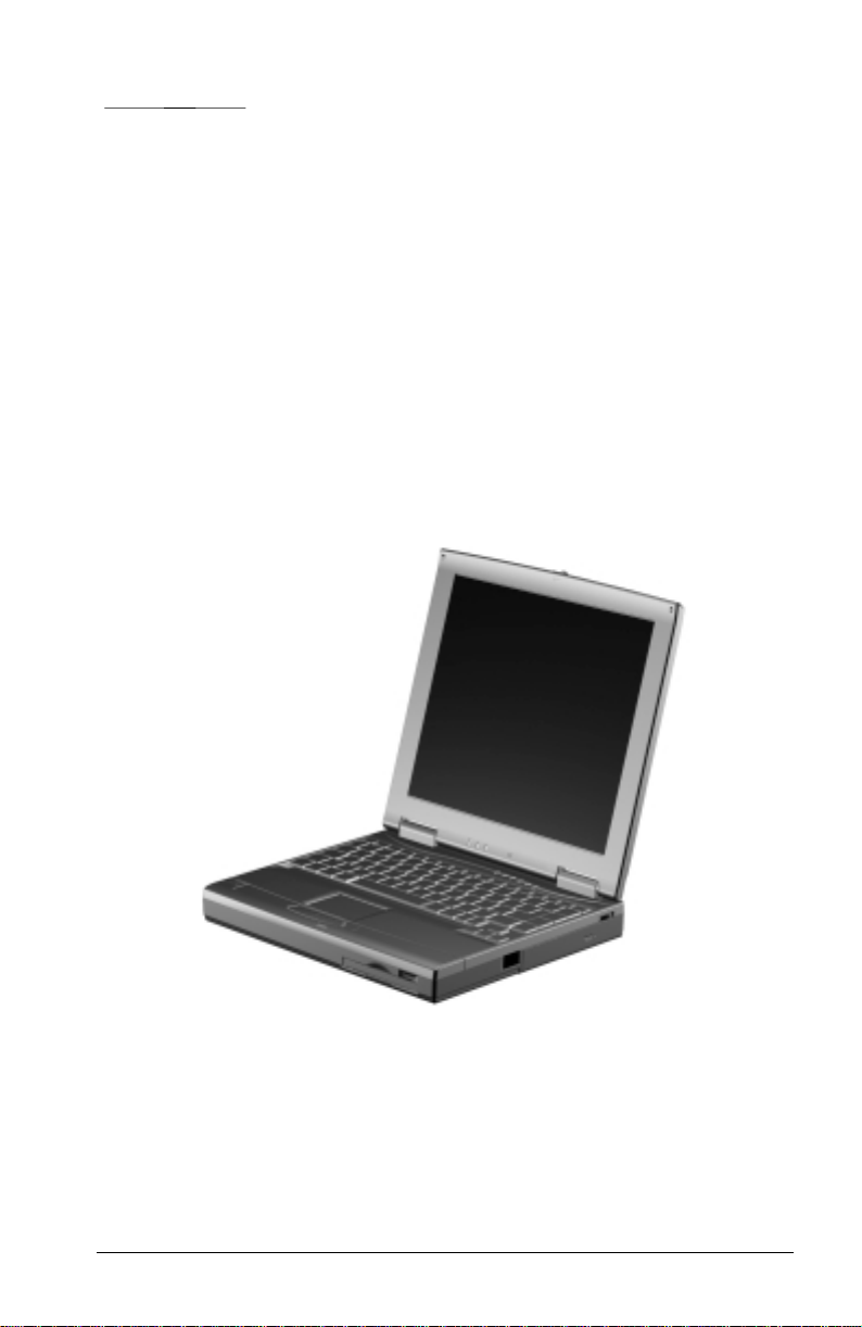
1.1 Computer Features and Models
The Compaq Notebook 100 Series offers an AMD K6-2 475-MHz
processor, a 12.1-inch SVGA TFT or HPA display, a 5.0-GB hard drive,
and a 24X Max CD-ROM drive. The computer also comes equipped with
a TouchPad pointing device and 4 MB of video SDRAM.
Figure 1-1. Compaq Notebook 100 Series
Product Description 1-1
Page 4
Models
The Compaq Notebook 100 Series is available in the models shown in
Table 1-1. The computer serial number is located on a bar code on the
bottom of the computer and identifies the model’s features.
Table 1-1
Compaq Notebook 100
Model Naming Convention
Example: serial number N10 K2 475 T1S 5 M 64 98
Key
A K2 475 T2S 5 M 64 98
1 2345678
KEY DESCRIPTION OPTIONS
1 Brand designator A = Notebook 100
2 Processor K2 = AMD k6-2
3 Processor speed 475 = 475-MHz
4 Display T2S = 12.1”, CTFT, SVGA H2S = 12.1”, HPA, SVGA
5 Hard drive size (MB) 5 = 5.0 MB
6 Integrated
communication
7 RAM (in MB) 64 = 64 MB 32 = 32 MB
8 Operating system 98 = Microsoft
M = Modem 0 = None
Windows 98
2 = Microsoft Word
2000
SB = Microsoft Small
Business
Table 1-2
Compaq Notebook 100 Models
12345678 SKU#
A K2 475 T2S 5 M 64 98/2 175844-XX4 FFG1
A K2 475 T2S 5 M 64 98 180641-XX4 FFG2
A K2 475 T2S 5 M 64 98 180641-XX5 FFG2
A K2 475 T2S 5 0 64 98/2 180097-XX4 FFG3
A K2 475 T2S 5 M 64 98/SB 175599-XX4 FFG4
A K2 475 H2S 5 M 32 98/2 175843-XX4 FFF1
A K2 475 H2S 5 M 32 98 180640-XX4 FFF2
A K2 475 H2S 5 M 32 98 180640-XX5 FFF2
A K2 475 H2S 5 0 32 98/2 180096-XX4 FFF3
A K2 475 H2S 5 M 32 98/SB 175598-XX4 FFF4
A K2 475 H2S 5 M 64 98/2 180095-XX4 FFF5
A K2 475 H2S 5 M 64 98/SB 180094-XX4 FFF6
1-2 Product Description
Config.
Code
Page 5

Features
The Compaq Notebook 100 Personal Computer has the following
features:
■ AMD K6-2 475-MHz processor with 512 KB integrated L2 cache.
■ 64-MB 100-MHz SDRAM, expandable to 192 MB, or 32-MB
100-MHz SDRAM, expandable to 160 MB, varying by computer
model. The Compaq Notebook 100 also features a SODIMM
memory expansion slot, capable of accepting a memory expansion
board of 32-, 64-, or 128-MB.
■ Primary memory cache is 64 KB; secondary memory cache is
512 KB.
■ 12.1-inch SVGA TFT or HPA (800 × 600) color display, varying by
computer model. These display feature:
■ over 16.8 million colors.
■ integrated Trident CyberBlade AGP2 controller bus.
The computer also features external monitor support with 4G color
(640 × 480, 800 ×600, 1024 ×768, 1280 ×1024), with up to 60-, 75-,
or 85-Hz refresh rate.
■ Microsoft Windows 98, professional or standard edition,
preinstalled.
■ Keyboard with TouchPad pointing device.
■ 56-Kbps AC97 modem (not supported in DOS mode).
■ External AC adapter with 6-foot power cord.
■ A 9-cell NiMH battery pack is standard equipment on the Compaq
Notebook 100 Personal Computer. An 8-cell Li ion battery pack is
available as an option.
■ One Type II PC Card slot with support for both 32-bit CardBus and
16-bit PC Cards.
■ Mass storage devices include a 5.0-GB hard drive, 3.5-inch,
1.44-MB diskette drive, and 24X Max CD-ROM drive.
■ Connectors for parallel, serial, audio in/out, external monitor,
universal serial bus, external keyboard, and AC power. An infrared
port is also available.
Product Description 1-3
Page 6
1.2 System Memory Options
Depending on the computer model, the main memory subsystem supports
a minimum of 32 or 64 megabytes of Synchronous SDRAM, expandable
to 160 or 192 megabytes. The minimum standard Synchronous SDRAM
is integrated on the system board. The upgrade SDRAM is accomplished
with memory expansion boards that are available on 128-, 64-, and 32megabytes.
The memory expansion slot is located underneath the fan/CPU cover.
Refer to Chapter 5, “Removal and Replacement Procedures,” for
information on installing and removing memory expansion boards.
System memory can be upgraded as shown in Table 1-3.
Table 1-13
Memory Upgrade
Base Memory on System Board Memory Expansion Board Total Memory
32 MB 32 MB 64 MB
32 MB 64 MB 96 MB
32 MB 128 MB 160 MB
64 MB 32 MB 96 MB
64 MB 64 MB 128 MB
64 MB 128 MB 192 MB
1-4 Product Description
Page 7

1.3 Power Management Functions
Power Management functions of the computer are designed to conserve
power. All Power Management functions can be configured from the
Setup Configuration Utility (SCU), described later in this chapter.
Automatic Power Management
Automatic Power Management operates at two levels as described in the
following paragraphs.
Local Power Management
Local Power Management controls computer subsystems. When a
subsystem is inactive for a period of time, it is automatically shut down
or slowed to reduce power consumption. The subsystem returns to an
active state when it is accessed.
Subsystems under Power Management include:
■ Hard disk drive
■ Diskette drive
■ CD-ROM drive
■ LCD display panel
Global Power Management
Global Power Management automatically puts the computer into Suspend
mode when the computer is inactive for a period of time. The computer
wakes up whenever activity resumes.
The time-out settings for Suspend mode are set up in the SCU program.
The computer uses Suspend-to-RAM (Standby) or Suspend-to-Disk
(Hibernation) depending on the Suspend Data To setting in the SCU
program.
Manual Power Management
Suspend mode can be initiated at any time in one of two ways:
■ By pressing Fn + F12.
■ By closing the top cover, if the Cover Close option is set to Suspend
in the SCU program.
Product Description 1-5
Page 8

Suspend-to-Disk (Hibernation)
When the computer suspends to disk, the system preserves all the running
application programs as a file in a Suspend-to-Disk partition on the hard
disk. The computer then turns off automatically. When the computer is
powered on, the system reads the file from the Suspend-to-Disk partition
back into memory, returning the computer to the state it was in before it
was suspended.
If there is no Suspend-to-Disk partition on the hard disk, use the
HIBERNAT utility to create the partition, in order to be able to use the
Suspend-to-Disk feature.
Suspend-to-RAM (Standby)
When the computer suspends to RAM, several subsystems enter standby
or power-off mode to conserve power. The system wakes up when any
key is pressed. Resume Timer and Ring Resume options also wake the
system from Suspend-to-RAM.
1.4 Setup Configuration Utility (SCU)
The system comes with a Setup Configuration Utility (SCU). This utility
configures BIOS settings via menu-driven utilities. Settings are stored in
the CMOS RAM.
The SCU must be used when:
■ An error message indicates that the SCU should be run.
■ Factory default settings need to be restored (after BIOS upgrades).
■ Specific settings must be modified.
Starting the SCU
The SCU resides on the system ROM chip. Start the utility by pressing
F10 during initial power up.
1-6 Product Description
Page 9

Main SCU Screen
The SCU main screen is divided into three areas:
Menu area – lists the available menu titles, across the top of the screen.
Each menu title provides a pull-down menu of item settings.
Display area – displays current system settings. This section also
displays submenus for items that provide multiple options.
Information and navigation area – provides keyboard/mouse
instructions for moving around and making decisions.
You can select items using either the keyboard or the TouchPad/mouse.
Product Description 1-7
Page 10

Startup Menu
The Startup pull-down menu contains basic system configuration
settings.
Startup Menu
Item Function Default
Date and
Time
Fast Boot When enabled, speeds up the booting
Boot
Device
Set Admin
password
Set User
password
Sets the system date and time. N/A
procedure by bypassing the memory test. This
option does not include a sub-menu. A check
mark indicates Enabled. An underline
indicates Disabled.
Sets the boot device sequence. If all booting
options are set to the same device, the
computer tries to boot only from that device.
Allows the creation of an administrator-level
password. This controls whether a nonadministrator can boot the system or enter the
SCU utility.
Sets up a user-level password. This controls
booting, running the SCU, or resuming the
system.
Enabled
Diskette A
Hard Drive C
CD-ROM Drive
■ An Administrator password must be set up prior to attempting to set
up a User password.
■ The Administrator password must be used to make changes in the
SCU. The User password only allows browsing.
1-8 Product Description
Page 11
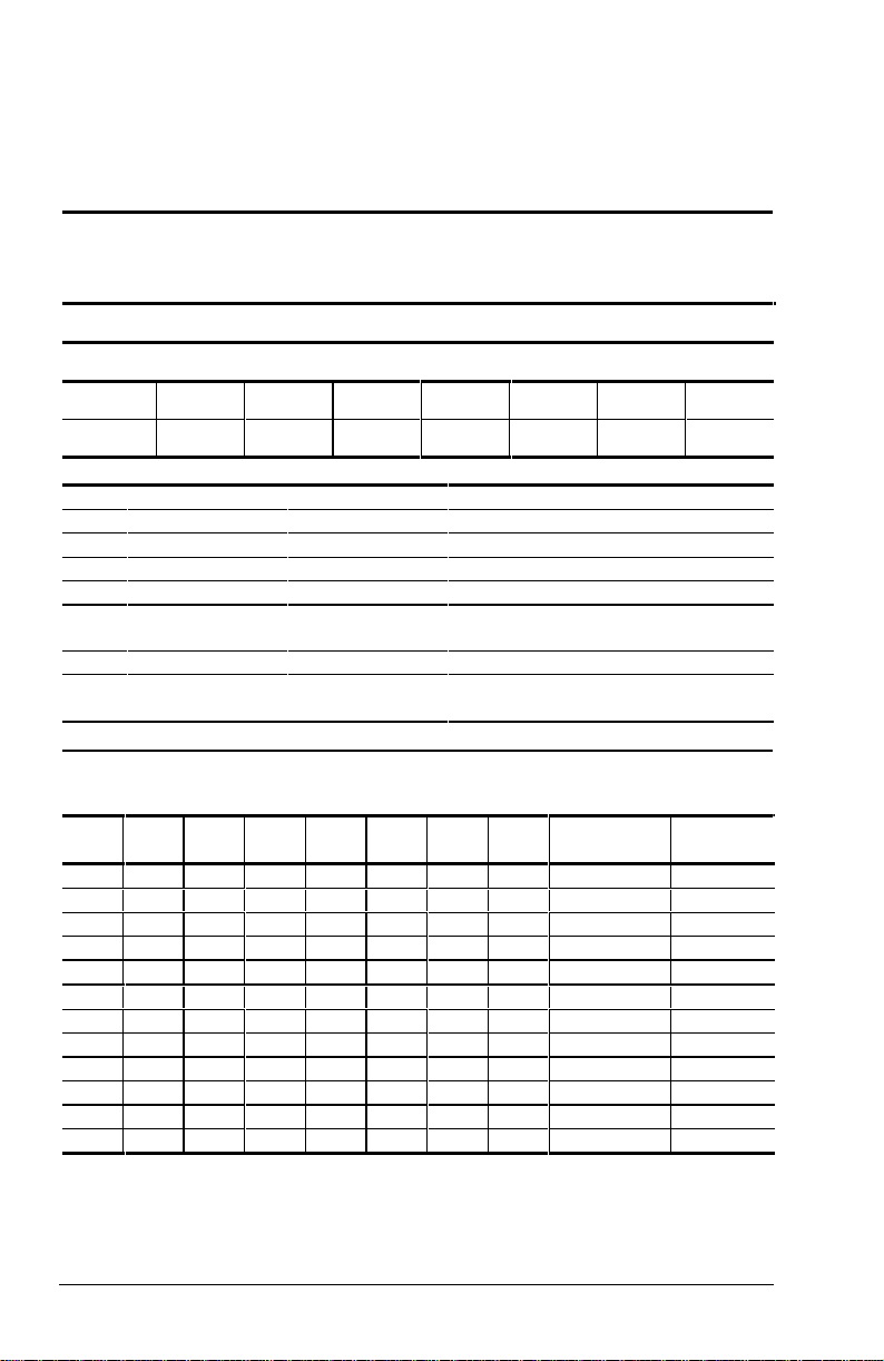
Memory Menu
The Memory pull-down menu controls memory usage. The setting
enables or disables usage of L2 cache memory. The default setting is
Enabled.
Disks Menu
The Disks menu contains settings that configure the system diskette drive
and hard drive. It also sets the virus alert option.
Product Description 1-9
Page 12

Disks Menu
Item Function Default
Internal
FDC
Sets when an internal diskette drive is present.
A check mark indicates that the item is
Enabled. An underline indicates Disabled.
Enabled
Diskette
Drives
Internal
HDC
IDE
Settings
Virus Alert Provides warning messages if the hard disk
Sets the type of diskette disk. 1.44MB
Sets when an internal hard drive is present. A
check mark indicates that the item is Enabled.
An underline indicates Disabled.
Sets the type of hard disk drive in the system.
HDD Timing – Sets the data transmit mode of
the hard drive. The default is Ultra DMA-33.
I/O 32 bit Transfer – If enabled, allows for a
faster transfer rate. The effect is more
noticeable under DOS. The default setting is
Enabled.
HDD Block Transfer – If enabled, allows for a
large capacity hard disk. The default setting is
Enabled.
boot sector (partition table) has changed. A
checkmark indicates that the item is Enabled.
An underline indicates Disabled.
Enabled
N/A
Enabled
1-10 Product Description
Page 13

Components Menu
The Components menu changes settings on various components such as
COM and LPT ports.
Components Menu
Item Function Default
Com Port Assigns COM1 and COM2 to specific
LPT Port Sets the address for the LPT (parallel) port.
Keyboard
Numlock
Keyboard
Repeat
functions. In general, assign COM1 to RS-232
(the serial port); then assign COM2 to IR.
Mode Setting for COM B – Sets the IR mode
for COM B. The mode depends on the type of
device that the computer will communicate
with.
This system supports Enhanced Parallel Port
(EPP) and Extended Capabilities Port (ECP)
standards. If the port is set to ECP, choose a
DMA channel setting for that port.
Sets the function of the numeric keypad. If you
disable this option, the numeric keypad on the
computer will not function, even if the Num
Lock indicator is on. However, an external
keyboard is not affected by this feature.
Sets the repeat rate and delay time of
keystrokes. The Key Repeat Rate sets the
repeat rate while holding down a key. The Key
Delay item sets delaying time between key
repeats.
Enabled
Product Description 1-11
Page 14
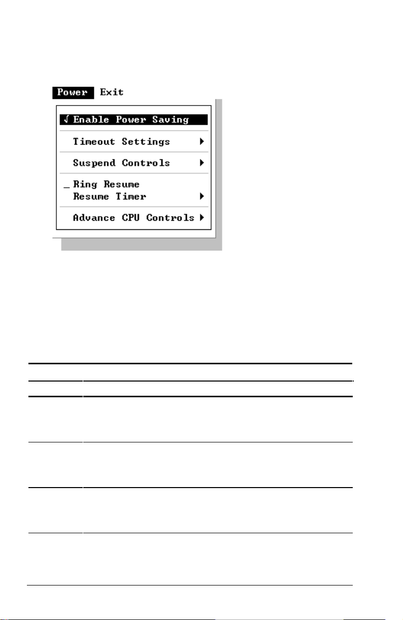
Power Menu
The Power menu contains Power Management settings that help conserve
system power.
Enable Power Saving – This is the master control for the Power
Management features. If disabled, all Power menu items with the
exception of Suspend Controls are automatically disabled.
Timeout Settings – Sets up timeout functions. Note that some operating
systems such as Windows 98 have built-in APM/ACPI configurations
that could override these settings.
Item Function
Video
Timeout
Disk
Timeout
Global
Timeout
1-12 Product Description
Sets the timeout period for the monitor to power down if not used
during a set period. The monitor powers up again when a key is
pressed. Available options are 30 Sec, 2 Min, 5 Min, 10 Min,
15 Min, and Always On.
Sets the timeout period for the hard disk to power down if not
accessed during the set period. The hard disk powers up again
when next accessed. Available options are 30 Sec, 1 Min,
1.5 Min, 2 Min, and Always On.
Sets the timeout period for the whole system to power down if
not in use during a specified period. The system powers up
again once any key is pressed. Available options are 1 Min,
2 Min, 4 Min, 6 Min, 8 Min, 12 Min, 16 Min, and Always On.
Power Menu
continued
Page 15

Power Menu continued
Item Function
Monitor
Video
Activity
Suspend
Timeout
Suspendto-Disk
Sets up the system to monitor video activity. If enabled, any
activity on the screen (such as displaying a movie) prevents the
monitor from powering down. Available options are Enabled or
Disabled.
Sets the timeout period for the system to enter Suspend Mode if
not in use during a pre-set period.
The Suspend Mode is determined by the “Suspend Type” item in
the “Suspend Controls” submenu. Choices may be Suspend-toRAM or Suspend-to-Disk.
When Suspend-to-RAM (Standby) mode is initiated, several
subsystems enter standby or power-off mode to conserve power.
The system wakes up when a key is pressed. “Resume Timer”
and “Ring Resume” items will also wake the system from
Suspend-to-RAM mode.
When Suspend-to-Disk (Hibernation) mode is initiated, the
system preserves all running application programs as a file in a
suspend-to-disk partition on the hard disk. Available options are
1 Min, 5 Min, 10 Min, 20 Min, 30 Min, and Never.
Sets the timeout period for the system to enter Suspend-to-Disk
mode if not in use during a set period.
When Suspend-to-Disk mode is initiated, the system preserves
all running application programs as a file in a suspend-to-disk
partition on the hard disk. Available options are 1 Min, 5 Min,
10 Min, 20 Min, 30 Min, and Never.
The Suspend-to-Disk item functions regardless of the “Suspend
Timeout” setting and the “Suspend Type” setting in the “Suspend
Controls” submenu. If the timing of this item is shorter that that of
“Suspend Timeout”, the system directly enters Suspend-to-Disk
mode if inactive for the timing.
Product Description 1-13
Page 16

Suspend Controls – Manages several suspend features.
Suspend Controls Menu
Item Function
Power
Button
Function
Lid Switch
Function
Suspend
Type
Sets the function of the Power button. Available options are
Power On/Off and Suspend/Resume. If this item is set to
Suspend/Resume, holding down the button for 5 seconds will
turn off power.
Sets the sequential event when the top cover is closed with
power still available. The available options are Blank LCD and
Suspend/Resume.
Sets the suspend mode the system enters if it stays inactive for
the time specified in the “Suspend Timeout” item.
Ring Resume – Enables or disables the system from waking up from
Suspend-to-RAM mode when the modem receives an incoming call.
Resume Timer – Sets the date and time the system resumes from
suspend mode. The default setting is Disabled.
Advance CPU Controls – Sets up further advanced CPU functions.
Advance CPU Controls Menu
Item Function
Clock
Control
Mechanism
Clock Run
Enable
Sets the CPU activity under normal condition. The available
options range from 6% to full speed (Disabled). Note that
although this item sets the usage of CPU resources, the CPU
can still reach its full speed if the system is under a heavy job
load.
Enables whether the system can take advantage of the
Southbridge chipset to help transmit data, thereby reducing the
CPU job load.
1-14 Product Description
Page 17
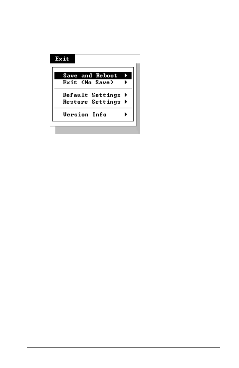
Exit Menu
The Exit pull-down menu displays ways of exiting SCU. This menu also
restores default settings and displays BIOS version information.
When troubleshooting the Compaq Notebook 100, it is important to
obtain all facts about the situation. Obtain details of the problem and any
circumstances surrounding the problem. Obtain all error codes or beep
codes. Once all facts have been gathered, determine possible causes and
search for issues.
Product Description 1-15
Page 18

1.5 Compaq Configuration Record Utility
Compaq Configuration Record Utility is an online information-gathering
tool meant to replace the DOS based Inspect utility. It runs from within
Windows and gathers critical hardware and software information from
various sources to give a complete view of the computer. The Compaq
Configuration Record Utility delivers comprehensive configuration
capture, provides a means for automatically identifying and comparing
configuration changes, and has the ability to maintain a computer
configuration history. The information can be saved as a history of
multiple sessions.
The Compaq Configuration Record Utility captures data as sessions; a
session is defined as an organized group of data describing the configured
state of the system at a specific point in time.
The session information is maintained in a log file, located in the same
directory as the executable portion of the program. This file contains all
of the ASCII text configuration information captured for a session. This
file can be analyzed locally by the Configuration Record Utility, or it can
be sent to another location such as a help center, or to Compaq.
The sessions are organized as two distinct types:
Active
The Active session (referenced as session now.log) is the most recent
information captured. The utility overwrites this session each time a
sample is taken.
Original
The Original session (referenced as session base.log) is the first session
sampled. The Compaq Configuration Record Utility will treat this
session as a "master configuration" and the utility will never overwrite
this session.
1-16 Product Description
Page 19
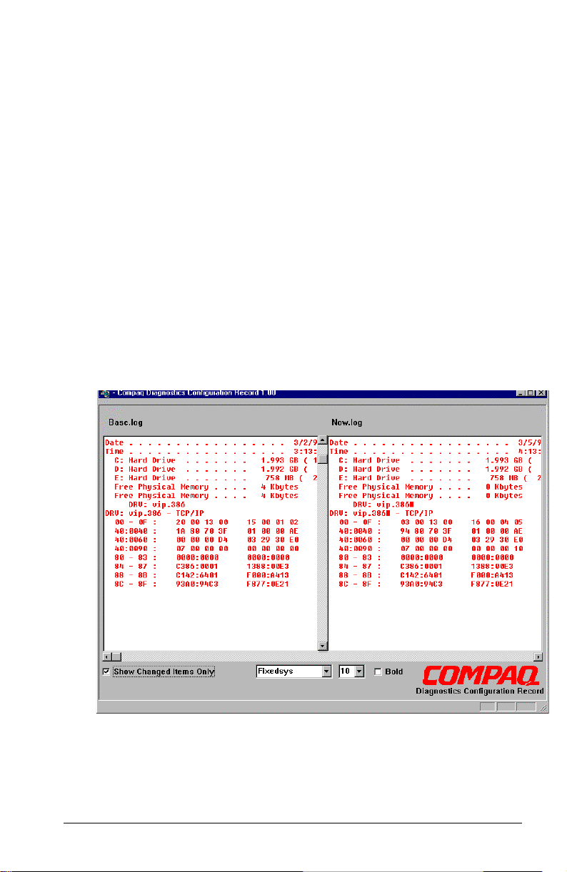
1.6 Gathering Information
The comparison feature provides several reports that enable the
administrator to specify the particular type and level of information that
will be most useful in a particular case. The different report types
available are:
Show Only Differences Report
This feature provides a mechanism for filtering the level of information
displayed when comparing two different configuration snapshots (or
sessions). For example, when a user requests that Configuration Record
Utility generate a comparison of sessions using the “differences” filter,
the tool automatically compares those two sessions (which are already
stored in a Configuration Record file). It then generates a report that
shows only the differences between the two generations. In this case, the
differences report will include all information recorded, such as changes
in amounts of free memory. Reviewing the differences occurring between
different configuration snapshots can help identify trends causing
intermittent computer problems, such as low memory resources.
Product Description 1-17
Page 20
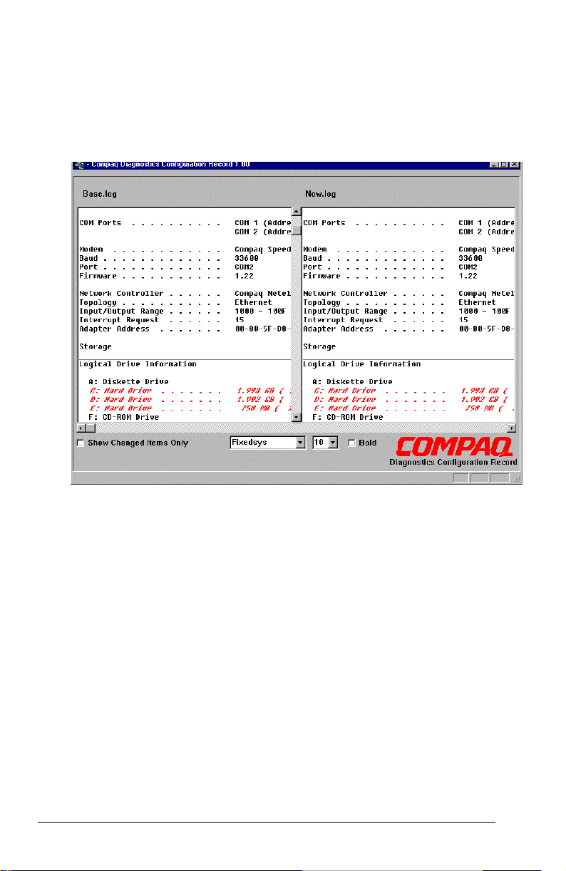
Show Details and Differences Report
This report provides the level of detail that is necessary for service
personnel to get a clear picture of the system configuration. It provides a
much greater depth of information on hardware, operating system
services, and drivers that are running on the computer.
The Compaq Configuration Record Utility is supported under
Windows 95, Windows 98, and Windows NT 4.0. This utility is available
on SoftPaq.
1-18 Product Description
Page 21

1.7 Diagnostics
Using Compaq Diagnostics
■ Access Compaq Diagnostics for Windows by selecting
StartÅSettingsÅControl PanelÅCompaq Diagnostics.
■ To select a category, choose one of two methods:
■ Select the Categories menu, then select a category from the drop-
down list.
■ Select a category icon on the toolbar.
To run diagnostic tests:
1. Select the Test tab.
2. In the scroll box, select the category or device you want
to test.
3. Select the Quick, Complete, or Custom test type.
4. Select the Interactive or Unattended test mode.
5. Select the Begin Testing button.
6. View test information by selecting a report from the Status, Log, or
Error tab.
■ To print the information or save it to a drive, select the File menu,
then select Print or Save As.
7. To exit, select the File menuÅExit.
Product Description 1-19
Page 22

1.8 Computer External Components
The external components on the display and right side of the computer
are shown in Figure 1-2 and described in Table 1-2.
Figure 1-2. Display and Right Side Components
Table 1-2
Display and Right Side Components
Item Component Function
1 TouchPad and touch
buttons
2 Keyboard Provides numeric keypad, 12 function keys,
3 Stereo speakers Produce high-quality stereo sound.
4 Activity lights Indicate AC/battery power, mass storage,
5 Display release latch Opens the computer.
6 Microphone Allows for audio input.
7 Volume control Adjusts the volume of the stereo speakers.
8 CD-ROM drive Accepts CD-ROM disks.
9 Infrared port Provides wireless communication between
10 Diskette drive Accepts 3.5-inch diskettes.
The TouchPad moves the mouse cursor,
selects, and activates.
The touch buttons function like the left and
right mouse button on an external mouse.
and special fn keys
and keyboard lock status.
the computer and another infraredequipped device using an infrared beam.
1-20 Product Description
Page 23
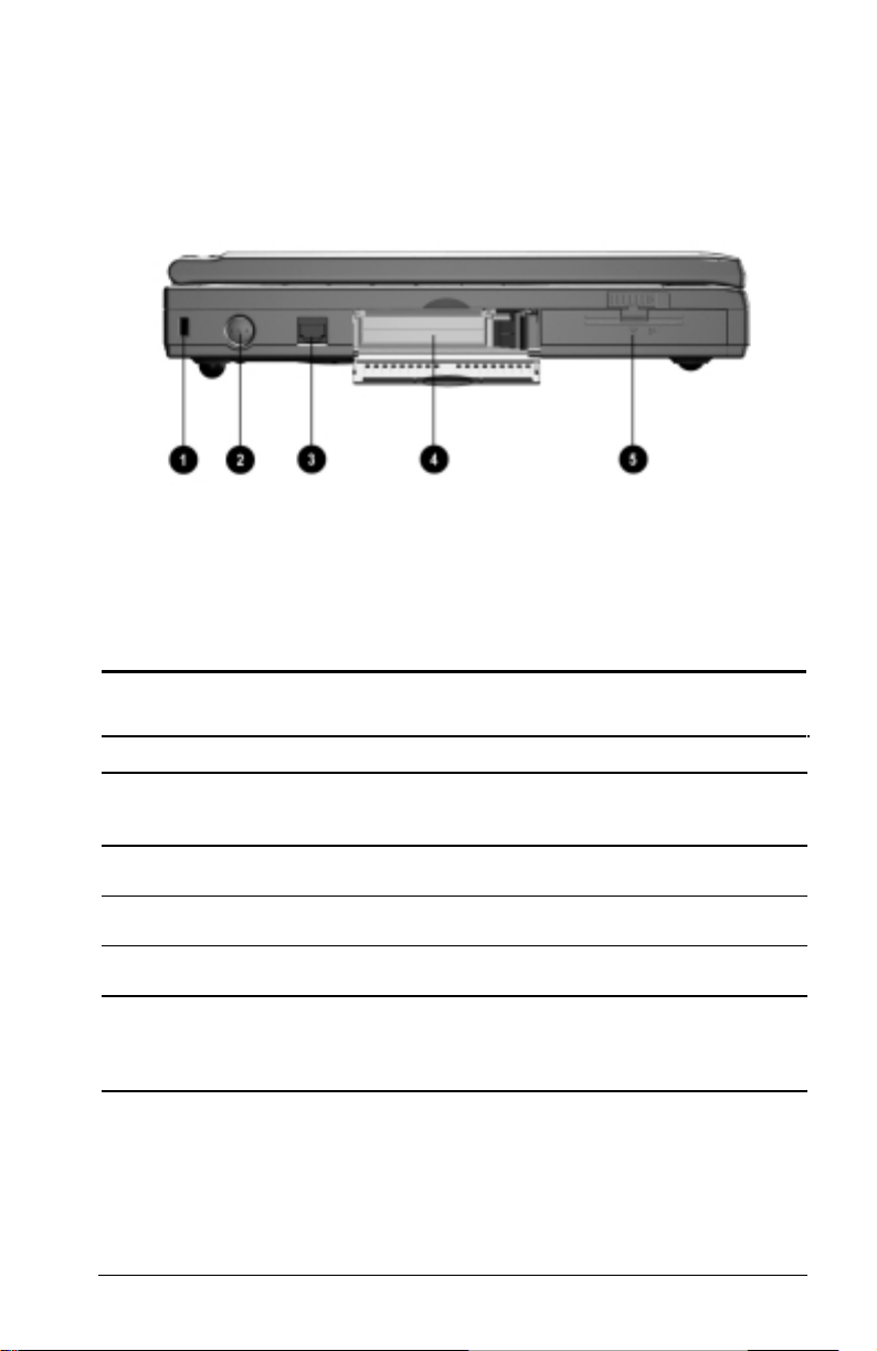
The external components on the left side of the computer are shown in
Figure 1-3 and are described in Table 1-4.
Figure 1-3. Left Side Components
Table 1-3
Left Side Components
Item Component Function
1 Security cable slot Accepts an optional security cable to secure
2 Power button Turns the computer on or off or exits
3 RJ-11 jack (internal
modem models only)
4 PC Card slot Supports 32-bit (CardBus) and 16-bit
5 Battery pack Accepts either the standard 9-cell NiMH or
the computer to a fixed object to prevent
theft.
Standby.
Connects the modem cable to an internal
modem.
PC Cards.
optional 8-cell Li ion battery packs. The
battery pack supplies power to the computer
of external power is not available.
Product Description 1-21
Page 24
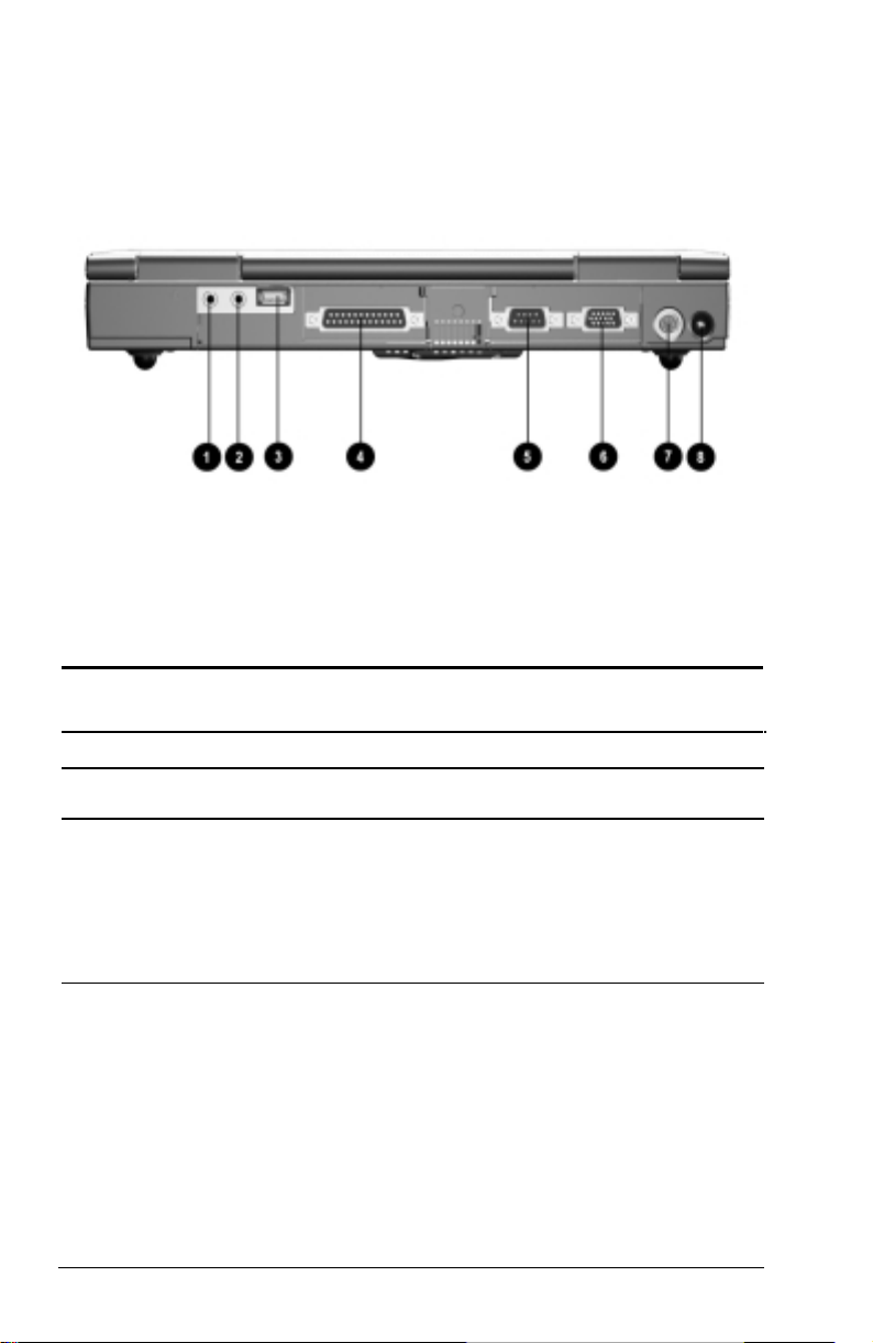
The external components on the rear of the computer are shown in Figure
1-4 and described in Table 1-5.
Figure 1-4. Rear Components
Table 1-4
Rear Components
Item Component Function
1 Mono microphone jack Connects a mono microphone, disabling
2 Stereo speaker/
headphone jack
the built-in microphone.
Connects stereo speakers, headphones, or
headset.
This jack is driven by an amplifier and has
volume control. The internal computer
speakers are turned off when external
speakers or headphones are plugged into
this jack.
continued
1-22 Product Description
Page 25

Table 1-4 continued
Item Component Function
3 Universal Serial Bus
(USB) connector
4 Parallel connector Connects an optional parallel device, such
5 Serial connector Connects optional serial devices, such as a
6 External monitor
connector
7 Keyboard/mouse
connector
8 AC Adapter connector Connects the AC power adapter.
Connects USB devices, such as cameras
for video conferencing, or hubs which
connect multiple USB devices.
The USB connector is a powered hub.
When running Windows 98, any
combination of up to five powered or
unpowered hubs can be connected in any
sequence, as long as two unpowered hubs
are not connected next to each other.
When running a lower version of Windows,
or if using a different operating system, up
to two hubs can be connected.
as a printer.
mouse.
Connects an optional external monitor,
overhead projector, or TV adapter.
Connects an optional full-sized keyboard or
a mouse. Both external mouse and
computer pointing device are active. An
optional splitter/adapter allows both an
external keyboard and mouse to be used at
the same time.
Product Description 1-23
Page 26

1.9 Design Overview
This section presents a design overview of key parts and features of the
computer. Refer to Chapter 3 for the illustrated parts catalog and
Chapter 5 for removal and replacement procedures.
The system board provides the following device connections:
■ Memory expansion board
■ Hard drive
■ Display
■ Keyboard/TouchPad
■ Audio
■ AMD K6-2 processor
■ Fan
■ PC Cards
■ Modem or modem/NIC
The Compaq Notebook 100 uses an electrical fan for ventilation. The fan
is controlled by a temperature sensor and is designed to turn on
automatically when high temperature conditions exist. These conditions
are affected by high external temperatures, system power consumption,
power management/battery conservation configurations, battery fast
charging, and software applications. Exhaust air is displaced through the
ventilation grill located on the right side of the computer.
CAUTION: To properly ventilate the computer, allow at least a
3-inch (7.6 cm) clearance on the left and right sides of the
computer.
1-24 Product Description
Page 27

chapter
2
TROUBLESHOOTING
2.1 Service Considerations
When troubleshooting the Compaq Notebook 100, it is important to
obtain all facts about the situation. Obtain details of the problem and any
circumstances surrounding the problem. Obtain all error codes or beep
codes. Once all facts have been gathered, determine possible causes and
search for issues.
2.2 Basic Troubleshooting Checklist
Use the following checklist in the event minor problems are encountered:
■ Is the computer connected to an external power source or does it
have a fully charged battery pack installed?
■ Is the computer turned on and is the power indicator illuminated?
■ Are all cables connected properly and secure?
■ Did the diskette drive contain a non-bootable diskette when the
system was powered up?
■ Does the computer have all necessary device drivers?
■ Have printer drivers been installed for each application?
■ Was the Windows operating system properly exited?
■ Has the computer hard drive been scanned for viruses?
Troubleshooting 2-1
Page 28

2.2 Power-On Self Test (Post)
When the computer starts, the system BIOS runs a series of internal
checks on the hardware. This allows the computer to detect problems as
early as the power-on stage. The POST alerts you to problems by
displaying error messages.
If POST detects an error, the system displays an error message on the
display. If the error occurs before the display comes up, error codes or
system beeps indicate the POST error.
The value for diagnostic POST (378H) is written at the beginning of the
test. Therefore, if the test fails, you can determine where the problem
occurred by reading the last value written to POST 378H by the PIO
Debug Board Plug at the PIO port. The following table lists error codes
in sequential order on the PIO Debug Board.
Table 2-1
Error Codes
Code Description
01h Start of boot loader sequence.
02h Initialize chipset.
03h Memory sizing.
04h Perform conventional RAM (1st 640K) test with crossed
pattern R/W.
05h Move boot loader to the RAM.
06h Start point of execution of boot loader in RAM.
07h Shadow screen BIOS.
08h Initialize clock synthesizer.
09h Initialize audio controller.
0Ah Detect internal ISA modem.
0Bh Proceed with normal boot.
0Ch Proceed with crisis boot.
0Fh DRAM sizing
10h Initial L1, L2 cache, make stack and diagnose CMOS.
11h Turn off fast A20 for post, Reset GDT’s, 8259’s quickly.
continued
2-2 Troubleshooting
Page 29

Table 2-1 continued
Code Description
12h Signal power on reset on COMS.
13h Initialize the chipset (DRAM).
14h Search for ISA bus VGA adapter.
15h Reset counter/timer 1, excite the RAM.
16h User register config through CMOS.
18h Dispatch to 1st 64K RAM test.
19h Checksum the ROM.
1Ah Reset PIC’s (8259s).
1Bh Initialize video adapter(s)
1Ch Initialize video (6845 regs).
1Dh Initialize color adapter.
1Eh Initialize monochrome adapter
1Fh Test 8237A page registers.
2Oh Perform keyboard self-test.
21h Test and initialize keyboard controller.
22h Check if CMOS RAM valid.
23h Test battery fail & CMOS X-SUM.
24h Test DMA controllers.
25h Initialize 8237 controller.
26h Initialize interrupt vectors table.
27h RAM quick sizing.
28h Protected mode entered safely.
29h RAM test completed.
2Ah Protected mode exit successful.
2Bh Setup shadow.
2Ch Prepare to initialize video.
2Dh Search for monochrome adapter.
2Eh Search for color adapter, VGA initialize
continued
Troubleshooting 2-3
Page 30

Table 2-1 continued
Code Description
2Fh Signon messages displayed.
30h Special init of keyboard ctlr.
31h Test if keyboard present.
32h Test keyboard interrupt.
33h Test keyboard command Byte.
34h Test, blank and count all RAM.
35h Protected mode entered safely (2).
36h RAM test complete.
37h Protected mode exit successfully.
38h Update keyboard output port to disable gate of A20.
39h Setup cache controller.
3Ah Test if 18.2Hz periodic working.
3Bh Initialize BIOS data area at 40.0.
3Ch Initialize the hardware interrupt vector table.
3Dh Search and initialize the mouse
3Eh Update NUMLOCK status.
3Fh OEM initialization of COM and LPT ports.
40h Configure the COM and LPT ports.
41h Initialize the diskette drive.
42h Initialize the hard disk.
43h OEM’s unit of PM with USB.
44h Initialize additional ROMs.
45h Update NUMLOCK status.
46h Test for coprocessor installed.
47h OEM’s unit of power management (check SMI).
48h OEM’s functions before boot (PC Card, CardBus).
49h Dispatch to operation system boot.
4Ah Jump into bootstrap code.
2-4 Troubleshooting
Page 31

2.3 Solving Common Problems
Table 2-2
Power
Problem Possible Cause Solution
The power button is
pressed and nothing
happens. The power
indicator does not
light up.
No AC or battery
power.
Table 2-3
Display
Problem Possible Cause Solution
There is no display
on either the internal
LCD or an external
monitor.
I/O devices and
cables causing a
problem.
■ Check to ensure the
AC adapter is
plugged in.
■ Check to ensure the
battery is charged.
■ Try another working
battery or adapter.
■ Try a working monitor
or LCD.
■ Check SW4 for
proper switch settings
■ Remove I/O devices
and cables and
reconnect one by one
to determine which is
causing the problem.
Table 2-4
VGA Controller Failure
Problem Possible Cause Solution
There is no display
on either the internal
LCD or an external
monitor, yet the
system passed
POST.
Faulty LCD or
Monitor
■ Try another working
monitor or LCD
module.
■ Remove I/O devices
and cables and
reconnect one by one
to determine which is
causing the problem.
Troubleshooting 2-5
Page 32

Table 2-5
LCD No Display
Problem Possible Cause Solution
The LCD shows
nothing or abnormal
picture. The picture
is fine on an external
monitor.
■ Improper switch
settings.
■ Faulty LCD
display.
■ Cables not
installed
properly.
■ LCD is not active
(toggle Fn + F5)
■ Check to see if SW4
is set properly.
■ Discharge CMOS for
wrong display mode
setting.
■ Try a working LCD
display.
■ Check if D/A BD is
good.
■ Make sure cables are
installed properly.
Table 2-6
External Monitor No Display
Problem Possible Cause Solution
The CRT monitor
shows nothing or
abnormal color. The
picture is fine on the
LCD.
■ Monitor power
cord not installed
properly.
■ CRT monitor
cable not
installed properly
■ CRT monitor is
faulty.
■ External display
not active
(toggle Fn + F5)
■ Check the monitor’s
power cord
■ Check the CRT
monitor cable.
■ Try a working
monitor.
■ Check the CMOS
settings
2-6 Troubleshooting
Page 33

2.4 Test Errors
The following topics contain checklists to help isolate and correct errors
generated during POST.
Memory Test Error
■ Check extended SDRAM modules for proper installation.
■ Visually inspect the SDRAM socket for bent pins.
■ Try a working SDRAM module.
Keyboard Test Error
■ Check the keyboard cable.
■ If using an external PS/2 keyboard, ensure that it is working properly
by testing a working keyboard.
Diskette Drive Test Error
■ Ensure that BIOS is set up correctly. Use the SCU to verify.
■ Ensure that the diskette drive is connected properly.
■ Try another working diskette drive.
CD-ROM Drive Test Error
■ Try another working CD.
■ Ensure that the CD-ROM drive is connected properly.
■ Try another working CD-ROM drive.
Hard Drive Test Error.
■ Check the CMOS hard disk drive settings.
■ Try another working hard disk drive.
Troubleshooting 2-7
Page 34

USB Board Test Error
■ Ensure that the USB device is installed properly.
■ Ensure that the USB driver is installed.
■ Verify that the USB device conforms to the correct standard, UHCI
as opposed to OHCI.
■ Try another working UHCI device.
Serial Port Test Error
■ Ensure that the mouse or other I/O devices are installed properly
(including associated drivers).
■ Check CMOS to ensure that the COM port is set properly.
■ Try another working device.
Parallel Port Test Error
■ Ensure that the PIO device is installed properly.
■ Check the CMOS LPT port settings
■ Try another working device.
Audio Failure
■ Ensure that all cables and devices are connected properly.
■ Ensure that the appropriate software drivers are installed.
■ Try another working speaker, cable, and CD-ROM.
■ Ensure that there are no address or IRQ conflicts.
2-8 Troubleshooting
Page 35

chapter
3
ILLUSTRATED PARTS CATALOG
This chapter provides an illustrated parts breakdown and a reference for
spare part numbers and option part numbers for the Compaq Notebook
100 Personal Computer.
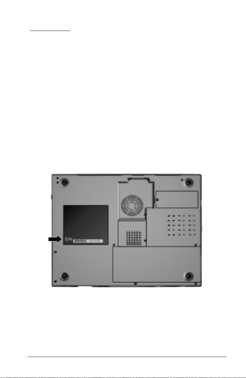
3.1 Serial Number Location
When ordering parts or requesting information, provide the computer
serial number and model number located on the bottom of the computer
(Figure 3-1).
Figure 3-1. Serial Number Location
Illustrated Parts Catalog 3-1
Page 36

3.2 Computer System Major Components
Figure 3-2. Computer System Major Components
3-2 Illustrated Parts Catalog
Page 37

Table 3-1
Spare Parts: Computer System Major Components
Item Description Spare Part Number
1 Display assembly
2a
2b
2c
2d
2e
2f
2g
3a
3b
3c
3d
4 Keyboard 176041-XXX
5 Top cover 176043-001
6 EMI shield 176002-001
7 TouchPad 176044-001
8 Hard drive
9 System board
10 Diskette drive 176047-001
11a
11b
11c
12 Base assembly 176042-001
13 Battery pack
14 AMD K6-2 475-MHz processor 176036-001
15 24X CD-ROM drive 176039-001
16 56 Kbps modem 176052-001
17 Fan assembly 176051-001
12.1-inch panel, HPA (used only with
config. codes beginning with “FFF”)
12.1-inch panel, TFT (used only with
config. codes beginning with “FFG”)
Miscellaneous Plastics Kit, includes:
Left and right hinge covers
Speaker housing
RJ11 cover
PC Card door
I/O cover
Modem cover
Fan/CPU cover
Hardware Kit, includes:
Speakers (2)
Real time clock battery and sponge
Processor bracket
Modem shield
Brazilian
French
German
International
Italian
Japanese
5.0 GB 176040-001
64 MB SDRAM (used only with config. codes
“FFG1” through “FFG4”)
64 MB SDRAM (used only with config. codes
“FFF5” and “FFF6”)
32 MB SDRAM (used only with config. codes
“FFF1” through “FFF4)
Cable Kit, includes:
Diskette drive cable
Modem cable
CD-ROM drive cable
NiMH (standard)
Li ion (available only as an option)
-201
-051
-041
-002
-061
-291
Latin American
Spanish
Portuguese
Spanish
U.K. English
U.S. English
176037-001
176038-001
176048-001
176049-001
189047-001
176035-001
176034-001
176004-001
174373-001
174372-001
-161
-131
-071
-031
-001
Illustrated Parts Catalog 3-3
Page 38

3.3 Miscellaneous Plastics Kit Components
Figure 3-3. Miscellaneous Plastics Kit Components
Table 3-2
Miscellaneous Plastics Kit Components
Spare Part Number 176048-001
Item Description
1 Left and right hinge covers
2 Speaker housing
3 RJ11 cover
4 PC Card door
5 I/O cover
6 Modem cover
7 Fan/CPU cover
3-4 Illustrated Parts Catalog
Page 39

3.4 Hardware Kit Components
Figure 3-4. Hardware Kit Components
Hardware Kit Components
Spare Part Number 176049-001
Item Description
1 Speakers (2)
2 Real time clock battery
3 Processor bracket
4 Modem shield
Table 3-3
Illustrated Parts Catalog 3-5
Page 40

3.5 Cable Kit Components
Figure 3-5. Cable Kit Components
Spare Parts: Cable Kit Components
Spare Part Number 176004-001
Item Description
1 Diskette drive cable
2 Modem cable
3 CD-ROM drive cable
Table 3-4
3-6 Illustrated Parts Catalog
Page 41

3.6 Mass Storage Devices
Figure 3-6. Mass Storage Devices
Table 3-5
Spare Parts: Mass Storage Devices
Item Description Spare Part Number
1 5.0-GB hard drive 176040-001
2 24X CD-ROM drive (standard) 176039-001
3 Diskette drive, 1.44-Megabyte 176047-001
Illustrated Parts Catalog 3-7
Page 42

3.7 Miscellaneous
Table 3-6
Spare Parts: Miscellaneous (Not Illustrated)
Description Spare Part Number
Power cord, black, 6 feet 246959-XXX
Australian
Danish
International
Italian
Japanese
PC Cards
Compaq Microcom 420 56K Global Modem
Compaq Netelligent 10/100 TX network card
Compaq Microcom 500 10/100 +56K combination
modem/network interface card
AC Adapter, 50 W 174371-001
Miscellaneous Screw Kit 176050-001
Memory expansion board
128 MB
64 MB
32 MB
Compaq Notebook 100 Maintenance & Service Guide 190369-001
-011
-081
-021
-061
-291
Korean
Swiss
U.K. English
U.S. English
-AD1
-AG1
-031
-001
317900-001
335506-B12
321550-B21
179966-001
179965-001
179964-001
3-8 Illustrated Parts Catalog
Page 43

chapter
4
REMOVAL AND REPLACEMENT
PRELIMINARIES
This chapter provides essential information for proper and safe removal
and replacement service.
4.1 Tools Required
You will need the following tools to complete the removal and
replacement procedures:
■ Magnetic Phillips screwdriver
■ Tool kit (includes connector removal tool, loopback plugs, and case
utility tool)
4.2 Service Considerations
Listed below are some of the considerations that you should keep in mind
during disassembly and assembly procedures.
IMPORTANT: As you remove each subassembly from the computer, place
it (and all accompanying screws) away from the work area to prevent
damage.
Plastic Parts
Using excessive force during disassembly and reassembly can damage
plastic parts. Use care when handling the plastic parts. Apply pressure
only at the points designated in the maintenance instructions.
Removal and Replacement Preliminaries 4-1
Page 44

Cables and Connectors
Cables must be handled with extreme care to avoid damage. Apply only
the tension required to unseat or seat the cables during removal and
insertion. Handle cables by the connector whenever possible. In all cases,
avoid bending, twisting, or tearing cables. Ensure that cables are routed
in such a way that they cannot be caught or snagged by parts being
removed or replaced. Handle flex cables with extreme care; they tear
easily.
CAUTION: When servicing the computer, ensure that cables are
placed in their proper location during the reassembly process.
Improper cable placement can damage the computer.
4.3 Preventing Damage to Removable Drives
Removable drives are fragile components that must be handled with care.
To prevent damage to the computer, damage to a removable drive, or loss
of information, observe these precautions:
■ Before removing or inserting a hard drive, shut down the computer.
If you are unsure whether the computer is off or in Hibernation, turn
the computer on, then shut it down.
■ Before removing a diskette drive or CD-ROM drive, ensure that a
diskette or disc is not in the drive. Ensure that the CD-ROM tray is
closed.
■ Before handling a drive, ensure that you are discharged of static
electricity. While handling a drive, avoid touching the connector.
■ Handle drives on surfaces that have at least one inch of shock-proof
foam.
■ Avoid dropping drives from any height onto any surface.
4-2 Removal and Replacement Preliminaries
Page 45

■ After removing a hard drive, place it into a static-proof bag.
■ After removing a CD-ROM drive or a diskette drive, place it into a
static-proof bag.
■ Do not use excessive force when inserting a drive into a drive bay.
■ Avoid exposing a hard drive to products that have magnetic fields
such as monitors or speakers.
■ Avoid exposing a drive to temperature extremes or to liquids.
■ If a drive must be mailed, do the following: place the drive into a
bubble pack mailer or other suitable form of protective packaging;
label the package “Fragile: Handle With Care.”
4.4 Preventing Electrostatic Damage
Many electronic components are sensitive to electrostatic discharge
(ESD). Circuitry design and structure determine the degree of sensitivity.
Networks built into many integrated circuits provide some protection, but
in many cases the discharge contains enough power to alter device
parameters or melt silicon junctions.
A sudden discharge of static electricity from a finger or other conductor
can destroy static-sensitive devices or microcircuitry. Often the spark is
neither felt nor heard, but damage occurs. An electronic device exposed
to electrostatic discharge may not be affected at all and can work
perfectly throughout a normal cycle. It may function normally for a
while, then degrade in the internal layers, reducing its life expectancy.
Removal and Replacement Preliminaries 4-3
Page 46

4.5 Packaging and Transporting Precautions
Use the following grounding precautions when packaging and
transporting equipment:
■ To avoid hand contact, transport products in static-safe containers
such as tubes, bags, or boxes.
■ Protect all electrostatic-sensitive parts and assemblies with
conductive or approved containers or packaging.
■ Keep electrostatic-sensitive parts in their containers until they arrive
at static-free workstations.
■ Place items on a grounded surface before removing them from their
container.
■ Always be properly grounded when touching a sensitive component
or assembly.
■ Place reusable electrostatic-sensitive parts from assemblies in
protective packaging or non-conductive foam.
■ Use transporters and conveyers made of antistatic belts and roller
bushings. Ensure that mechanized equipment used for moving
materials is wired to ground, and that proper materials were selected
to avoid static charging. When grounding is not possible, use an
ionizer to dissipate electric charges.
4.6 Workstation Precautions
Use the following grounding precautions at workstations:
■ Cover the workstation with approved static-dissipative material
(refer to Table 4-2 later in this chapter).
■ Use a wrist strap connected to a properly grounded work surface and
use properly grounded tools and equipment.
■ Use field service tools, such as cutters, screwdrivers, and vacuums
that are conductive.
■ When using fixtures that must directly contact dissipative surfaces,
use fixtures made of static-safe materials only.
■ Keep work area free of nonconductive materials such as ordinary
plastic assembly aids and Styrofoam.
■ Handle electrostatic-sensitive components, parts, and assemblies by
the case or PCM laminate. Handle them only at static-free
workstations.
4-4 Removal and Replacement Preliminaries
Page 47

■ Avoid contact with pins, leads, or circuitry.
■ Turn off power and input signals before inserting or removing
connectors or test equipment.
4.7 Grounding Equipment and Methods
Grounding equipment must include either a wrist strap or a foot strap at a
grounded workstation.
■ When seated, wear a wrist strap connected to a grounded system.
Wrist straps are flexible straps with a minimum of one megaohm
±10% resistance in the ground cords. To provide proper ground,
wear a strap snug against the skin at all times. On grounded mats
with banana-plug connectors, connect a wrist strap with alligator
clips.
■ When standing, use foot straps and a grounded floor mat. Foot straps
(heel, toe, or boot straps) can be used at standing workstations and
are compatible with most types of shoes or boots. On conductive
floors or dissipative floor mats, use them on both feet with a
minimum of one-megohm resistance between the operator and
ground. To be effective, the conductive strips must be worn in
contact with the skin.
■ Other grounding equipment recommended for use in preventing
electrostatic damage include:
■ Antistatic tape
■ Antistatic smocks, aprons, or sleeve protectors
■ Conductive bins and other assembly or soldering aids
■ Non-conductive foam
■ Conductive tabletop workstations with ground cord of one-megohm
resistance
■ Static-dissipative table or floor mats with hard tie to ground
■ Field service kits
■ Static awareness labels
■ Material-handling packages
■ Non-conductive plastic bags, tubes, or boxes
■ Metal tote boxes
■ Electrostatic Voltage Levels and Protective Materials
Removal and Replacement Preliminaries 4-5
Page 48

Table 4-1 shows how humidity affects the electrostatic voltage levels
generated by different activities.
Table 4-1
Typical Electrostatic Voltage Levels
Relative Humidity
Event 10% 40% 55%
Walking across carpet 35,000 V 15,000 V 7,500 V
Walking across vinyl floor 12,000 V 5,000 V 3,000 V
Motions of bench worker 6,000 V 800 V 400 V
Removing DIPS from plastic
tube
Removing DIPS from vinyl tray 11,500 V 4,000 V 2,000 V
Removing DIPS from Styrofoam 14,500 V 5,000 V 3,500 V
Removing bubble pack from
PCB
Packing PCBs in foam-lined
box
NOTE: A product can be degraded 700 volts.
Table 4-2 lists the shielding protection provided by antistatic bags and
floor mats.
2,000 V 700 V 400 V
26,500 V 20,000 V 7,000 V
21,000 V 11,000 V 5,000 V
Table 4-2
Static-Shielding Materials
Material Use Voltage Protection Level
Antistatic plastic Bags 1,500 V
Carbon-loaded plastic Floor mats 7,500 V
Metallized laminate Floor mats 15,000 V
4-6 Removal and Replacement Preliminaries
Page 49
Chapter
5
REMOVAL AND REPLACEMENT PROCEDURES
This chapter provides removal and replacement procedures for the
Compaq Notebook 100 Series.
5.1 Serial Number
Report the computer serial number to Compaq when requesting
information or ordering spare parts. The serial number is located on the
bottom of the computer (Figure 5-1).
Figure 5-1. Serial Number Location
Removal and Replacement Procedures 5-1
Page 50

5.2 Disassembly Reference Chart
Use the chart below to determine the section number to be referenced
when removing components from the computer.
5.3 Preparing the Computer for Disassembly
5.4 Battery Pack
5.5 Modem
5.6 Fan Assembly
5.7 CD-ROM Drive
5.8 Processor
5.9 Memory
Removing a Memory Expansion Board
Installing a Memory Expansion Board
5.10 Top Cover
5.11 Hard Drive
5.12 Real Time Clock (RTC) Battery
5.13 Keyboard
5.14 EMI Shield
5.15 TouchPad
5.16 Speakers
5.17 Display Assembly
5.18 Speaker Housing
5.19 System Board
5.20 Diskette Drive
5-2 Removal and Replacement Procedures
Page 51

5.3 Preparing the Computer for Disassembly
Perform the following steps before disassembling the computer. Consult
the computer reference guide for instructions on the steps below.
1. Remove any diskettes installed in the diskette drive.
2. Remove any CD-ROM discs installed in the CD-ROM drive.
3. Turn off the computer and close it.
4. Disconnect the AC Adapter and external devices.
5. Remove the battery pack (Section 5.4).
Removal and Replacement Procedures 5-3
Page 52

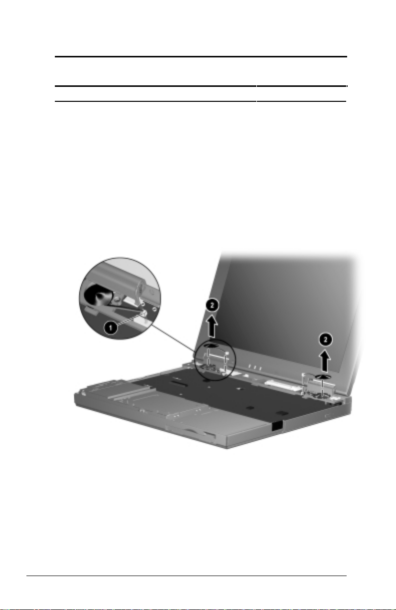
5.4 Battery Pack
Battery Pack
Spare Part Number Information
Battery pack, NiMH 174373-001
Battery pack, Li ion 174372-001
1. Prepare the computer for disassembly (Section 5.3).
2. Turn the computer bottom side up with the right side facing forward.
3. Lift the battery tab up
4. Slide the battery release switch to the left
5. Lift up the front edge of the battery pack and swing it away from
computer ➌.
6. Remove the battery pack.
➊ (Figure 5-2).
➋.
Figure 5-2. Removing the Battery Pack
Reverse the removal procedure described above to replace the battery
pack.
5-4 Removal and Replacement Procedures
Page 53

5.5 Modem
Modem
Spare Part Number Information
56Kbps modem board 176052-001
Modem cover (spared in Plastics Kit) 176048-001
Modem shield (spared in Hardware Kit) 176046-001
Modem cable (spared in Cable Kit) 176004-001
1. Prepare the computer for disassembly (Section 5.3).
2. Turn the computer bottom side up with the front facing forward.
3. Remove the screw
(Figure 5-3).
4. Lift the left side of the modem cover and swing it up and to the
➋.
right
5. Remove the modem cover.
➊ securing the modem cover to the base assembly
Figure 5-3. Removing the Modem Cover
Removal and Replacement Procedures 5-5
Page 54

6. Remove the two screws ➊ securing the modem shield to the
base assembly (Figure 5-4).
7. Remove the modem shield ➋.
Figure 5-4. Removing the Modem Shield
5-6 Removal and Replacement Procedures
Page 55

8. Swing the plastic modem protector toward the back of the
computer
➊ (Figure 5-5).
9. Disconnect the modem cable from the system board
10. Lift the left side of the modem board to disconnect it from the system
board ➌.
11. If necessary, disconnect the modem cable from the modem board and
replace the modem cable ➍.
➋.
Figure 5-5. Removing the Modem
12. Remove the modem board.
Reverse the removal procedure described above to replace the modem.
Removal and Replacement Procedures 5-7
Page 56

5.6 Fan Assembly
Fan Assembly
Spare Part Number Information
Fan assembly (includes fan shield, fan, and
heat sink)
Fan/CPU cover (spared in Plastics Kit) 176048-001
1. Prepare the computer for disassembly (Section 5.3).
2. Turn the computer bottom side up with the front facing forward.
3. Remove the four screws securing the fan/CPU cover to the base
assembly. Note that the two screws removed from the back edge of
the cover ➊ differ in size from the other two screws ➋ (Figure 5-6).
176051-001
4. Remove the fan/CPU cover
Figure 5-6. Removing the Fan/CPU Cover
➌.
5-8 Removal and Replacement Procedures
Page 57

5. Disconnect the fan cable ➊ from the system board (Figure 5-7).
6. Remove the four screws
board.
7. Remove the fan assembly
Figure 5-7. Removing the Fan Assembly
➋ securing the fan assembly to the system
➌.
Removal and Replacement Procedures 5-9
Page 58

5.7 CD-ROM Drive
CD-ROM Drive
Spare Part Number Information
24X Max CD-ROM drive 176039-001
CD-ROM drive cable (spared in Cable Kit) 176004-001
1. Prepare the computer for disassembly (Section 5.3).
2. Remove the fan assembly (Section 5.6).
3. Disconnect the CD-ROM drive cable from the system board
(Figure 5-8).
4. Remove the screw securing the CD-ROM drive to the base
assembly ➋.
5. Push on the back of the CD-ROM drive and slide the drive to the
left
➌.
➊
Figure 5-8. Removing the CD-ROM Drive
6. Remove the CD-ROM drive.
5-10 Removal and Replacement Procedures
Page 59

7. If necessary, disconnect the CD-ROM drive cable from the
CD-ROM drive (Figure 5-9).
Figure 5-9. Removing the CD-ROM Drive Cable
Reverse the removal procedure described above to replace the
CD-ROM drive.
Removal and Replacement Procedures 5-11
Page 60

5.8 Processor
Processor
Spare Part Number Information
475-MHz processor 176036-001
Processor bracket 176046-001
1. Prepare the computer for disassembly (Section 5.3).
2. Remove the fan assembly (Section 5.6).
3. Swing the left side of the processor bracket up and to the right
(Figure 5-10).
4. Remove the processor bracket
Figure 5-10. Removing the Processor Bracket
➋.
➊
5-12 Removal and Replacement Procedures
Page 61

5. Insert the tip of a flat-blade screwdriver into the left socket ➊. This
socket is marked “SKT OPEN” (Figure 5-11).
6. Swing the screwdriver to the right to release the processor ➋.
7. Remove the processor.
Figure 5-11. Removing the Processor
Removal and Replacement Procedures 5-13
Page 62

When replacing the processor, make sure the white square is in the
upper-right corner
socket (marked “SKT CLOSE)
to seat the processor
Figure 5-12. Replacing the Processor
➊. Insert the tip of the screwdriver into the right
➋ and swing the screwdriver to the right
➌ (Figure 5-12).
5-14 Removal and Replacement Procedures
Page 63

5.9 Memory
Memory Expansion Board
Spare Part Number Information
128 MB memory expansion board 179964-001
64 MB memory expansion board 179965-001
32 MB memory expansion board 179966-001
The Compaq Notebook 100 computer features one memory expansion
slot, located under the fan assembly.
Removing a Memory Expansion Board
1. Prepare the computer for disassembly (Section 5.3).
2. Remove the fan assembly (Section 5.6).
3. Spread the retaining tabs apart
upward (Figure 5-13).
4. Lift the edge of the memory expansion board and gently slide it out
of the memory expansion slot at a 45-degree angle
5. Place the memory expansion board in an electrostatic-safe container.
➊. The memory expansion board tilts
➋.
Figure 5-13. Removing a Memory Expansion Board
Removal and Replacement Procedures 5-15
Page 64

Installing a Memory Expansion Board
All memory expansion boards are asymmetrically keyed (notched) to
ensure correct positioning. Memory expansion boards can be used in
either memory expansion slot.
1. Insert the memory expansion board into an empty memory expansion
slot at a 45-degree angle
➊ (Figure 5-14).
2. Push the memory expansion board down
in the plastic retention clips.
Figure 5-14. Installing a Memory Expansion Board
➋ until the board is seated
5-16 Removal and Replacement Procedures
Page 65

5.10 Top Cover
Top Cover
Spare Part Number Information
Top cover 176043-001
1. Prepare the computer for disassembly (Section 5.3).
2. Turn the computer bottom side up, with the front facing forward.
3. Remove the six screws securing the top cover to the base assembly
(Figure 5-15).
Figure 5-15. Removing the Top Cover Screws
4. Turn the computer top side up, with the front facing forward.
5. Open the computer.
Removal and Replacement Procedures 5-17
Page 66

6. Lift up the front edge of the top cover ➊ and swing it toward the
back of the computer
Figure 5-16. Removing the Top Cover
7. Remove the top cover.
IMPORTANT: When installing the top cover, align the five tabs on the
back edge of the top cover with the slots in the speaker housing.
➋ (Figure 5-16).
5-18 Removal and Replacement Procedures
Page 67

5.11 Hard Drive
Hard Drive
Spare Part Number Information
5.0 GB hard drive 176040-001
1. Prepare the computer for disassembly (Section 5.3).
2. Remove the top cover (Section 5.10).
3. Remove the two screws securing the hard drive to the base
assembly
➊ (Figure 5-17).
4. Lift up the right side of the hard drive
to the right
Figure 5-17. Removing the Hard Drive
5. Remove the hard drive.
Reverse the removal procedure described above to replace the hard drive.
➌ to disconnect it from the TouchPad assembly.
➋, and then pull the hard drive
Removal and Replacement Procedures 5-19
Page 68

5.12 Real Time Clock (RTC) Battery
NOTE: Removal of the RTC battery clears all information from CMOS.
Real Time Clock Battery
Spare Part Number Information
Real time clock battery (spared in Hardware Kit) 176049-001
1. Prepare the computer for disassembly (Section 5.3).
2. Remove the top cover (Section 5.10).
3. Disconnect the RTC battery cable from the TouchPad
(Figure 5-18).
4. Remove the RTC battery from the base assembly
Figure 5-18. Removing the RTC Battery
Reverse the removal procedure described above to replace the
RTC battery.
➊
➋.
5-20 Removal and Replacement Procedures
Page 69

5.13 Keyboard
Keyboard
Spare Part Number Information
Keyboard 176041-XXX
Brazilian
French
German
International
Italian
Japanese
1. Prepare the computer for disassembly (Section 5.3).
2. Remove the top cover (Section 5.10).
-201
-051
-041
-002
-061
-291
Latin American
Spanish
Portuguese
Spanish
U.K. English
U.S. English
-161
-131
-071
-031
-001
Removal and Replacement Procedures 5-21
Page 70

3. Lift up the front edge of the keyboard ➊ and swing it back toward
the display (Figure 5-19).
4. Release the ZIF (zero insertion force) connector to which the
keyboard cable is attached
➋.
5. Disconnect the keyboard cable from the system board
Figure 5-19. Releasing the Keyboard and Disconnecting the
Keyboard Cable
6. Remove the keyboard.
IMPORTANT: When installing the keyboard, align the three tabs on the
back edge of the keyboard with the slots in the EMI shield.
➌.
5-22 Removal and Replacement Procedures
Page 71

5.14 EMI Shield
EMI Shield
Spare Part Number Information
EMI shield 176002-001
1. Prepare the computer for disassembly (Section 5.3).
2. Remove the top cover (Section 5.10).
3. Remove the keyboard (Section 5.13).
4. Remove the 12 screws securing the EMI shield to the base assembly
(Figure 5-20).
NOTE: There are three different-sized screws removed in this step: the
silver screws are removed/installed in location
screws are removed/installed in location
removed/installed in location
➌.
➊; the longer black
➋; the shorter black screw is
Also note that one of the silver screws
cable to the EMI shield.
Figure 5-20. Removing the EMI Shield Screws
➍ secures the display ground
Removal and Replacement Procedures 5-23
Page 72

5. Lift up the front edge of the shield and swing it toward the back of
computer (Figure 5-21).
Figure 5-21. Removing the EMI shield
6. Remove the EMI shield.
Reverse the removal procedure described above to replace the EMI
shield.
5-24 Removal and Replacement Procedures
Page 73

5.15 TouchPad
TouchPad
Spare Part Number Information
TouchPad 176044-001
1. Prepare the computer for disassembly (Section 5.3) and, in the order
below, remove the following components:
■ top cover (Section 5.10)
■ hard drive (Section 5.11)
■ RTC battery (Section 5.12)
■ keyboard (Section 5.13)
■ EMI shield (Section 5.14)
2. Lift the back edge of the TouchPad to disconnect it from the system
➊ (Figure 5-22).
board
3. Remove the TouchPad
Figure 5-22. Removing the TouchPad
Reverse the removal procedure described above to replace the TouchPad.
➋.
Removal and Replacement Procedures 5-25
Page 74
5.16 Speakers
Speakers
Spare Part Number Information
Speakers (2; spared in Hardware Kit) 176049-001
1. Prepare the computer for disassembly (Section 5.3) and, in the order
below, remove the following components:
■ top cover (Section 5.10)
■ keyboard (Section 5.13)
■ EMI shield (Section 5.14)
2. Disconnect the speaker cables from the system board
(Figure 5-23).
3. Remove the speakers from the speaker housing
Figure 5-23. Removing the Speakers
➋.
➊
Reverse the removal procedure described above to replace the speakers.
5-26 Removal and Replacement Procedures
Page 75

5.17 Display Assembly
Display Assembly Components
Spare Part Number Information
12.1-inch panel, HPA 176037-001
12.1-inch panel, TFT 176038-001
Left and right hinge covers (spared in Plastics
Kit)
1. Prepare the computer for disassembly (Section 5.3) and, in the order
below, remove the following components:
■ top cover (Section 5.10)
■ keyboard (Section 5.13)
■ EMI shield (Section 5.14)
2. Use a flat blade screwdriver to gently pry up and remove the left and
right hinge covers (Figure 5-24).
176048-001
Figure 5-24. Removing the Hinge Covers
Removal and Replacement Procedures 5-27
Page 76

3. Open the computer as far as it will open.
4. Disconnect the display video cable
microphone cable
Figure 5-25. Disconnecting the Display Cables
➌ (Figure 5-25).
➊, display inverter cable ➋, and
5-28 Removal and Replacement Procedures
Page 77

5. Remove the four screws ➊ securing the display hinges to the base
assembly (Figure 5-26).
6. Remove the display assembly ➋.
NOTE: Make sure the display assembly is supported and does not fall
when the screws are removed.
Figure 5-26. Removing the Display Assembly
Removal and Replacement Procedures 5-29
Page 78

When installing the display assembly, make sure the display video
cable
➊ is routed behind the left speaker connector ➋ on the system
board (Figure 5-27).
Figure 5-27. Routing the Display Video Cable
5-30 Removal and Replacement Procedures
Page 79

When replacing the display assembly, it is imperative that the DIP
switches are correctly set. To set the display DIP switches on the system
board, follow the steps below.
1. Remove the display assembly.
2. Locate the part number label on the display microphone cable ➊
(Figure 5-28).
3. Part number “441668500001/176038-001” corresponds to the
12.1-inch, TFT display assembly. If this is the part number on the
label, make sure the display DIP switch on the system board is set
according to setting ➋.
4. Part number “441668500002/176037-001” corresponds to the
12.1-inch, HPA display assembly. If this is the part number on the
label, make sure the display DIP switch on the system board is set
according to setting ➌.
Figure 5-28. Setting the Display DIP Switches
5. After the DIP switch settings have been verified, reassemble the
computer.
Removal and Replacement Procedures 5-31
Page 80

5.18 Speaker Housing
Speaker Housing
Spare Part Number Information
Speaker housing (spared in Plastics Kit) 176048-001
I/O cover (spared in Plastics Kit) 176048-001
1. Prepare the computer for disassembly (Section 5.3) and, in the order
below, remove the following components:
■ top cover (Section 5.10)
■ keyboard (Section 5.13)
■ EMI shield (Section 5.14)
■ display assembly (Section 5.17)
2. Position the computer so the rear panel faces forward.
3. Remove the screw securing the I/O cover to the speaker housing
(Figure 5-29).
4. Flex the middle of the I/O cover away from the computer
Figure 5-29. Removing the I/O Cover
5. Remove the I/O cover.
➋.
➊
5-32 Removal and Replacement Procedures
Page 81

6. Remove the five screws securing the speaker housing to the base
assembly
➊ (Figure 5-30).
7. Remove the speaker housing
Figure 5-30. Removing the Speaker Housing
Reverse the removal procedure described above to replace the speaker
housing.
➋.
Removal and Replacement Procedures 5-33
Page 82

5.19 System Board
System Board
Spare Part Number Information
System board with 32 MB SDRAM 176034-001
System board with 64 MB SDRAM 176035-001
RJ11 cover (spared with Plastics Kit) 176048-001
PC Card door (spared with Plastics Kit) 176048-001
1. Prepare the computer for disassembly (Section 5.3) and, in the order
below, remove the following components:
■ top cover (Section 5.10)
■ hard drive (Section 5.11)
■ RTC battery (Section 5.12)
■ keyboard (Section 5.13)
■ EMI shield (Section 5.14)
■ TouchPad (Section 5.15)
■ speakers (Section 5.16)
■ display assembly (Section 5.17)
■ speaker housing (Section 5.18)
2. Turn the computer bottom side up with the rear panel facing forward.
5-34 Removal and Replacement Procedures
Page 83

3. Remove the two screws securing the system board to the
base assembly (Figure 5-31).
Figure 5-31. Removing the System Board Screws
4. Turn the computer top side up with the front facing forward.
Removal and Replacement Procedures 5-35
Page 84
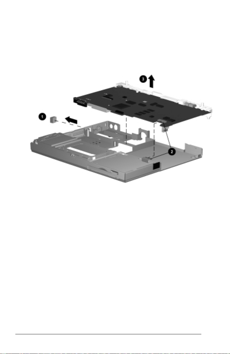
5. If installed, remove the RJ11 cover from the left side of the computer
➊ (Figure 5-32).
6. Disconnect the diskette drive LIF (low insertion force) cable from
the system board
➋.
7. Remove the system board from of the base assembly
Figure 5-32. Removing the System Board
IMPORTANT: When installing the system board, make sure the
diskette drive cable does not get trapped underneath the system board.
➌.
5-36 Removal and Replacement Procedures
Page 85

If necessary, remove the PC Card door by partially opening the door ➊,
flexing the middle of the door away from the computer ➋, and removing
the door (Figure 5-33).
Figure 5-33. Removing the PC Card Door
Removal and Replacement Procedures 5-37
Page 86

5.20 Diskette Drive
Diskette Drive
Spare Part Number Information
Diskette drive, 1.44 MB 176047-001
Diskette drive cable (spared in Cable Kit) 176004-001
1. Prepare the computer for disassembly (Section 5.3) and, in the order
below, remove the following components:
■ top cover (Section 5.10)
■ hard drive (Section 5.11)
■ RTC battery (Section 5.12)
■ keyboard (Section 5.13)
■ EMI shield (Section 5.14)
■ TouchPad (Section 5.15)
■ speakers (Section 5.16)
■ display assembly (Section 5.17)
■ speaker housing (Section 5.18)
■ system board (Section 5.19)
5-38 Removal and Replacement Procedures
Page 87

2. Lift the back edge of the diskette drive ➊ and swing it up and toward
the front of the base assembly
Figure 5-34. Removing the Diskette Drive
3. Remove the diskette drive.
➋ (Figure 5-34).
Removal and Replacement Procedures 5-39
Page 88
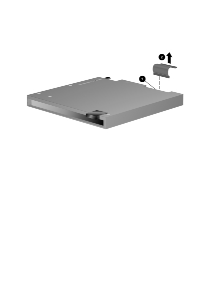
If necessary, remove the diskette drive cable by releasing the ZIF
connector
(Figure 5-35).
➊ to which the cable is attached and disconnecting the cable ➋
Figure 5-35. Disconnecting the Diskette Drive Cable
5-40 Removal and Replacement Procedures
Page 89

When installing the diskette drive, first insert the front of the drive
through the opening in the base assembly
the drive into the base assembly
back of the drive fits inside the diskette drive shield (Figure 5-36).
Figure 5-36. Installing the Diskette Drive
➋. Make sure the FPC cable ➌ on the
➊, then lower the back edge of
Removal and Replacement Procedures 5-41
Page 90

appendix
A
CONNECTOR PIN ASSIGNMENTS
Table A-1
RJ-11
Connector Pin Signal
1
1
7
3
2
8
654
2
3
4
5
6
7
8
NC_J3A
NC_J3B
TIP
RING
NC_J3C
NC_J3D
Unused
Unused
Table A-2
Serial Connector
13
Pin Signal Pin Signal
1 Carrier Detect 6 Data Set Ready
2 Receive Data 7 Ready to Send
3 Transmit Data 8 Clear to Send
4 Data Terminal Ready 9 Ring Indicator
5 Ground
49852
76
Connector Pin Assignments A-1
Page 91

Table A-3
Microphone Jack
Connector Pin Signal
1
1
2
2
Audio in
Ground
Table A-4
Stereo Speaker/Headphone Jack
Connector Pin Signal
1
1
2
2
Audio out
Ground
Table A-5
Stereo Line-in Jack
Connector Pin Signal
1
1
2
2
Audio in
Ground
A-2 Connector Pin Assignments
Page 92

Table A-6
Parallel Connector
5678910111213
1820 1921222325 24
151617 14
Pin Signal Pin Signal
1 Strobe 14 Auto Linefeed
2 Data Bit 0 15 Error
3 Data Bit 1 16 Initialize Printer
4 Data Bit 2 17 Select In
5 Data Bit 3 18 Ground
6 Data Bit 4 19 Ground
7 Data Bit 5 20 Ground
8 Data Bit 6 21 Ground
9 Data Bit 7 22 Ground
10 Acknowledge 23 Ground
11 Busy 24 Ground
12 Paper End 25 Ground
13 Select
1234
Connector Pin Assignments A-3
Page 93

Table A-7
Docking Connector
30
60
90
120
Pin Signal Pin Signal
1 EBOXL 29 XA3/R IN
2 AGND 30 MID0/MIC IN
3 EBOXS1 31 AUGND
4 RED 32 XA0/L OUT
5 AGND 33 XSD/MIC SN
6 GREEN 34 XA1/R OUT
7 AGRD 35 GND
8 BLUE 36 GND
9 AGND 37 EXPCLK2
10 VSYNC 38 +3.3V
11 HSYNC 39 EXPCLK0
12 DDC DAT 40 +5V (8051VCC)
13 DDC CLK 41 EXPCLK
14 GND 42 EBOXS2
15 INDEX 43 GND
16 RDATA 44 EBOXL
17 TRK0 45 EBOXL /GND
18 WDATA 46 SRDY
19 WGATE 47 EBOXS1 /GND
20 STEP 48 RI1 EX
21 DIR 49 GND
22 POWER ON 50 SLCT LD0
23 SYS RESET 51 PE LD1
24 GND 52 ACK LD2
25 DSKCHG 53 BUSY LD3
26 +5 V (VDD) 54 GND
27 AUGND 55 STRB LD4
28 XA2/L IN 56 ALF LD5
1
31
61
91
Continued
A-4 Connector Pin Assignments
Page 94

Table A-7 continued
Pin Signal Pin Signal
57 INIT LD6 91 PS2 VCC
58 SLCTIN LD7 92 SERIRQ
59 GND 93 PS2 CLK
60 PDATA0 LD8 94 EXPREQ
61 PDATA1 LD9 95 AD[29]
62 PDATA2 LD10 96 AD[31]
63 PDATA3 LD11 97 AD[30]
64 GND 98 AD[28]
65 PDATA4 LD12 99 AD[26]
66 PDATA5 LD13 100 GND
67 PDATA6 LD14 101 AD[24]
68 PDATA7 LD15 102 AD[22]
69 GND 103 AD[20]
70 ERROR LCLK 104 AD[18]
71 RXD1 LVREQ 105 AD[16]
72 TXD1 LCREQ 106 GND
73 RTS1 LEN 107 AD[15]
74 GND 108 AD[13]
75 CTS1 LIIC CLK 109 AD[11]
76 DTR1 LIIC DAT 110 AD[09]
77 DSR1 EX 111 GND
78 DCD1 EX 112 AD[06]
79 12C DATA 113 AD[04]
80 GND 114 AD[02]
81 12C CLK 115 AD[00]
82 GND 116 GND
83 HDSEL 117 FRAME
84 GND 118 TRDY
85 WPROT 119 STOP
86 EBOXS2 /GND 120 PAR
87 ERDY 121 CBE0
88 EBOXL /GND 122 CBE1
89 FLUSHREQ 123 GND
90 MEMACK 124 KB CLK
Continued
Connector Pin Assignments A-5
Page 95

Table A-7 continued
Pin Signal Pin Signal
125 RSVD1/M CTRL2 151 AD[12]
126 XSC/L OUT SN 152 AD[10]
127 RSVD2/M OFF HOOK 153 AD[08]
128 KB DATA 154 GND
129 MGND 155 AD[07]
130 STANDBY 156 AD[05]
131 M DRZP 157 AD[03]
132 M DRXN 158 AD[01]
133 VBATT 159 GND
134 EXPGNT 160 CBE3
135 VBATT 161 CBE2
136 GND 162 IRDY
137 VBATT 163 DEVSEL
138 PS2 DATA 164 LOCK
139 VBATT 165 OERR
140 AD[25] 166 SERR
141 VBATT 167 GND
142 AD[27] 168 RSVD3
143 VBATT 169 M 12C CLK
144 AD[23] 170 M 12C DATA
145 GND 171 M RING
146 AD[21] 172 MGND
147 AD[19] 173 M DXTN
148 AD[17] 174 GND
149 GND 175 M DXTP
150 AD[14] 176 MSTRBAT
A-6 Connector Pin Assignments
Page 96

Table A-8
External Keyboard/Mouse Connector
Connector Pin Signal
65
43
KEY
1
2
1
2
3
4
5
6
Keyboard/Mouse DATA
Keyboard/Mouse DATA
Ground
+5 VDC
Keyboard/Mouse CLK
Keyboard/Mouse CLK
Table A-9
External Monitor Connector
45
10
KEY
1623
87
1112131415
Pin Signal Pin Signal
1 Red Analog 9 NC
2 Green Analog 10 Ground
3 Blue Analog 11 NC
4 NC 12 DDC Data
5 Ground 13 Horizontal Sync
6 Ground 14 Vertical Sync
7 Ground 15 DDC Clock
8 Ground
Connector Pin Assignments A-7
Page 97

appendix
B
POWER CORD SET REQUIREMENTS
3-Conductor Power Cord Set
The wide range input feature of the Compaq Notebook 100 Personal
Computer permits it to operate from any line voltage from 100 to 120 or
220 to 240 volts AC.
The power cord sets received with the computers meets the requirements
for use in the country where the equipment is purchased.
Power cord sets for use in other countries must meet the requirements of
the country where the computer is used. For more information on power
cord set requirements, contact a Compaq authorized reseller or service
provider.
General Requirements
The requirements listed below are applicable to all countries:
1. The length of the power cord set must be at least 5.00 feet (1.5 m)
and a maximum of 6.50 feet (2.0 m).
2. All power cord sets must be approved by an acceptable accredited
agency responsible for evaluation in the country where the power
cord set will be used.
3. The power cord set must have a minimum current capacity of 10A
and a nominal voltage rating of 125 or 250 volts AC, as required by
each country’s power system.
4. The appliance coupler must meet the mechanical configuration of an
EN 60 320/IEC 320 Standard Sheet C13 connector, for mating with
appliance inlet on the back of the computer.
Power Cord Set Requirements B-1
Page 98

Country-Specific Requirements
3-Conductor Power Cord Set Requirements—By Country
Applicable Note
Country Accredited Agency
Australia EANSW 1
Austria OVE 1
Belgium CEBC 1
Canada CSA 2
Denmark DEMKO 1
Finland FIMKO 1
France UTE 1
Germany VDE 1
Italy IMQ 1
Japan JIS 3
The Netherlands KEMA 1
Norway NEMKO 1
Sweden SEMKO 1
Switzerland SEV 1
United Kingdom BSI 1
United States UL 2
Numbers
Notes
1. The flexible cord must be <HAR> Type HO5VV-F, 3-conductor,
1.0 mm2 conductor size. Power cord set fittings (appliance coupler
and wall plug) must bear the certification mark of the agency
responsible for evaluation in the country where it will be used.
2. The flexible cord must be Type SPT-3 or equivalent, No. 18 AWG,
3-conductor. The wall plug must be a two-pole grounding type with
a NEMA 5-15P (15A, 125V) or NEMA 6-15P (15A, 250V)
configuration.
3. The appliance coupler, flexible cord, and wall plug must bear a "T"
mark and registration number in accordance with the Japanese
Dentori Law. The flexible cord must be Type VCT or VCTF,
3-conductor, 0.75mm2 conductor size. The wall plug must be a
two-pole grounding type with a Japanese Industrial Standard C8303
(15A, 125V) configuration.
B-2 Power Cord Set Requirements
Page 99

INDEX
A
AC Adapter
spare part number, 3-8
specifications, 6-6
advance CPU controls menu, 1-14
applications. See software
B
base enclosure
illustrated, 3-2
spare part number, 3-3
battery pack, 5-4
illustrated, 3-2
Li ion
spare part number, 3-3, 5-4
specifications, 6-7
NiMH
spare part number, 3-3, 5-4
specifications, 6-7
removing, 5-4
C
Cable Kit
components
illustrated, 3-2, 3-6
spare part number, 3-3, 3-6
cables, 4-2
CD-ROM drive, 5-10
cable
disconnecting
from CD-ROM drive, 5-11
from system board, 5-10
illustrated, 3-2, 3-6
illustrated, 3-2, 3-7
removing, 5-10
spare part number, 3-3, 3-7, 5-10
specifications, 6-6
components menu, 1-11
computer
features, 1-3
major components
illustrated, 3-2
models, 1-2
specifications, 6-1
configuration record utility, 1-16
connector
pin assignments, A-1
connectors, 4-2
D
design overview, 1-24
diagnostics, 1-19
disassembly
preparing the computer, 5-3
reference chart, 5-2
diskette drive, 5-38
cable
disconnecting
from diskette drive, 5-40
from system board, 5-36
illustrated, 3-6
illustrated, 3-2, 3-7
installing, 5-41
removing, 5-39
spare part number, 3-3, 3-7, 5-38
specifications, 6-5
disks menu, 1-9
display assembly, 5-27
cables
disconnecting, 5-28
DIP switches
setting, 5-31
components, 1-20
illustrated, 3-2
removing, 5-29
video cable
routing, 5-30
12.1-inch
spare part number, 3-3, 5-27
12.1-inch, STN
specifications, 6-3
12.1-inch, TFT
specifications, 6-3
docking
connector
pinout, A-4
DOS. See MS-DOS
drivers. See device drivers
Index I-1
Page 100

E
electrostatic
preventing damage, 4-3
voltage levels, 4-6
EMI shield
illustrated, 3-2
removing, 5-23
spare part number, 3-3, 5-23
ESD. See electrostatic discharge
exit menu, 1-15
external monitor
connector
illustrated, 1-23
F
fan assembly, 5-8
illustrated, 3-2
removing, 5-9
spare part number, 3-3, 5-8
fan/CPU cover
illustrated, 3-2, 3-4
removing, 5-8
features, 1-3
floppy disk drive. See diskette drive
G
gathering information, 1-17
grounding
equipment, 4-5
methods, 4-5
H
hard drive
illustrated, 3-2, 3-7
removing, 5-19
spare part number, 3-3, 3-7, 5-19
specifications, 6-4
Hardware Kit
components
illustrated, 3-2, 3-5
spare part number, 3-3, 3-5
headphone
jack
pinout, A-2
Hibernation, 1-6
hinge covers
illustrated, 3-2, 3-4
removing, 5-27
I
I/O address. See input/output address
I/O cover
illustrated, 3-2, 3-4
removing, 5-32
IRQ. See interrupt requests
K
keyboard
cable
disconnecting, 5-22
connector
illustrated, 1-23
pinout, A-7
illustrated, 3-2
removing, 5-21
spare part number, 3-3, 5-21
L
left side components, 1-21
M
mass storage devices
illustrated, 3-7
spare part numbers, 3-7
memory, 5-15
expansion board
installing, 5-16
removing, 5-15
128 MB
spare part number, 5-15
32 MB
spare part number, 3-8, 5-15
64 MB
spare part number, 5-15
menu, 1-9
options, 1-4
upgrade table, 1-4
microphone
jack
pinout, A-2
I-2 Index
 Loading...