

Page 1
Operator's Manual
3/8 in. (10 mm) CORDLESS DRILL-DRIVER
Vadable Speed / Reversible
Model No.
315.101860 - 14.4 Volt
Save this manual for
future reference
,_ WARNING: To reducethe riskofinjury,
the usermustread and understandthe
operator'smanual beforeusingthis
product.
Customer Help Line: 1-800-932-3188
Sears, Roebuck and Co., 3333 Beverly Rd., Hoffman Estates, IL 60179 USA
Visit the Craftsman web page: www.sears.com/craftsman
983000-.409
6-04
Page 2
• Warranty........................................................................................................................................................................... 2
I Introduction...................................................................................................................................................................... 2
• General SafetyRules................................................................................................................................................... 3-4
I SpecificSafety Rules ....................................................................................................................................................... 4
• Safety Instructions forCharger ........................................................................................................................................ 5
• Symbols ........................................................................................................................................................................... 6
• Features....................................................................................................................................................................... 7-8
• Unpacking........................................................................................................................................................................ 8
• Operaifon .................................................................................................................................................................... 9-14
• Maintenance................................................................................................................................................................... 15
• Notes.............................................................................................................................................................................. 16
• Explodod View and Repair PartsList............................................................................................................................. 17
• Parts Ordering/ Service................................................................................................................................................. 18
FULL ONE YEAR WARRANTY ON COMPANION CORDLESS 3/8 In. DRILL-DRIVER
If this Sears Drill-Driverfails togive complete satisfactionwithinoneyear from the date of purchase, RETURN IT TO
THE NEAREST SEARS STORE OR SEARS SERVICE CENTER IN THE UNITED STATES_ and Sears will replaceit,
free of charge.
If this Sears CordlessDiflI-Driverisused for commemialor rentalpurposes,thiswarrantyappliesfor only 90 daysh'om
the date of purchase.
This warrantygivesyou specificlegal rights,and you may also have other rightswhichvary fromstate to state.
Sears, Roebuck end Co., Dept. 817 WA, Hoffman Estates, IL 60179
This toolhasmany fsaturesfor makingthe useof this
productmore pleasant and enjoyable.Safety,
performance, and dependabilityhave been giventop
priodty in the designof this productmaking it easy to
maintainand operate.
A Look for this symbol to point out important safety precautions. It
means attentionl!! Your safety is involved,
_l, WARNING: Do notattemptto usethisproduct
untilyoumad thoroughly and understandcomplataiy
the operator'smanual Paydose attentiontothe
safety rules,includingDangers,Warnings,and
Cautions.If you usethisproductproperlyand only
as intended,you willenjoyysar_ of safe, reliable
service.
WARNING:
The operation of any tool can result in foreignobjects being thrown into your eyes, which can
resultin severe eye damage. Beforebeginningpower tool operation, alwayswear safety goggles
or safety glasses with side shields and a full face shield when needed. We recommend Wide
VisionSafety Mask for use over eyeglasses or standardsafety glasses with sideshields. Always
wear eye protectionwhich is marked to complywith ANSI 7.87.1.
2
Page 3
_i WARNING! READ AND UNDERSTAND ALL
INSTRUCTIONS, Failure to followall instruCtions
listedbelow,may resultin electricshock,fireand/or
seriouspersonaliniury.
SAVE THESE INSTRUCTIONS
WORKAREA
• Keep your work area clean and well lit. Cluttered
benchesand dark areas Inviteaccidents.
• Do not operate power tools in explcelve atmo-
spheres, such as In the presence of flammable
liquids, gee(m, or dust. Powerfools create sparks
whichmayIgnitethe dustor fumes,
• Keep bystanders, children, end visitors away while
operating a power tool. Dtstractfonscancauseyouto
losecontrol.
ELECTRICAL SAFETY
• A battery operated tool with Integral batteries or a
separate battery pack must be recharged only with
the specified charger for the battery.A chargerthat
may be suitableforone type of batterymay createa
riskoffirewhen used withanother battery.
• Use battery operated tool only with specifically
designated battery pack. Use of anyotherbatteries
may create a riskoffire.
• Use battery only wlth charger listed.
[]ODEL BAI"I'IERYPACK CHARGER
315.101880 130122041 140209023
• Do not abuse the cord. Never use the cord to carry
the charger. Keep cord sway from heat, o11,sharp
edges, or moving parts. Replace damaged cords
Immediately. Damaged cordsmay create a fire.
PERSONAL SAFETY
• Stay alert, watch what you are doing and use
common sense w'nenoperatfng a power tool Do
not use tool while tired or under the Influence of
drugs, alcohol, or merllcation. A momentof inatten-
lion while operatingpower tools may msuH inserious
personalinjury.
• Dreea properly. Do not wear loose clothing or
Jewelry.Contain long heir. Keep your hair, clothing,
and gloves away from moving parts, Looseclothes,
jewelry,or long haircan be caught in movingpads.
• Avoid accidental atorUng. Be sure switch Is In the
lucked or off position before Incertlng battery pack.
Carryingtoolswith yourfingeron the switchor inserting
the batterypackintoa tool withthe switchon invites
accidents.
• Remove e_uatlng keys or wrenches before turning
the tool on. A wrenchor a key that isleft attachedto a
rotating partof the tool may resultin personalinjury,
• Do not overreach. Keep proper footing end balance
at all times. Properfootingandbalance enable better
controlofthetool in unexpeCtedsituations.
• Use safety equlpmenL Always wear eye protection.
Oustmask, non-skidsafetyshoes,hard hat,or hearing
protectionmustbe usedfor appropriateconditions,
• Do not wear loose clothing or jewelry. Contain long
hair. Loose d,othes,jewelry,or longhair can be drawn
intoai_vents.
• Do not use on a ladder or unstable support. Stable
foo,dngon a sol)dsurtacaenables better controlof the
toolin unexpectedsituations.
TOOL USE AND CARE
• Use clamps or other precUcstway to secure and
support the wod_ to a atabls platform. Holding
the workbyhandor againstyourbody Is unstableand
may lead totossof control
• Do not force tool, Use the correct tool for your
application. The correcttoolwilldo thejobbetter and
ea_eratthe rate forwh'_hitis designed.
• Do not use tool If switch doe6 notturn It on or off. A
tool thatcannotbe controlledwiththeswitchis danger~
ous and mustbe repaired.
• Disconnect battery pack from tool or place the
switch In the locked or off _ tx_fora _
any adjua_ment_ changing ac_mr,orlse, or storing
the tool, Such preventive safetymeasures reduce the
riskof startingthe toot accidan'm,y.
• Store Idle tools out of reach of children and other
untrafoed parsons. Toolsare dangerousinthe hands
of untrainedusers.
• When battery pack is not In use, keep It away from
other metal objects like: paper clips, coins, keys,
nails, screws, or other small metal objects that can
make a connection from one terminal to another.
Sho_ng the battery termi_ts togethermay cause
sparks,bums, era tim.
• Malntatn tools wfth care. Keep cutting tools sharp
end clean. Properlymaintainedtoolswithsharp cuffing
edges am lessfikelyto bindand are easier tocontrol.
[] Check for mlsstlgnment or binding of moving paris,
brenkage of parts, and any other condition tllat may
affect the tool's operation. If damaged, have the tool
serviced before using. Many accidentsare causedby
poorlymaintained tools.
[] Use only eooeasorles that are recommended by the
manufacturer for your model Accessoriesthatmay
be suitableforone tool mayoreale a riskof iniurywhen
used onanothertcoi.
• Keep the tool and Its handle dry, clean end free
from Oil and grease. Alwaysuse a cleanclothwhen
cleaning,Never use brakefluids,gasoline,petroleum-
based products,or anystrongsolventstoclean your
tool. Followingthisrole willreducethe riskof lossof
oont_ro{and deteriorationoft'r_eenclosure plastic.
Page 4
SERVICE
• Tool service must be performed only by qualified
repair personnel. Service or maintenancepedormed
byunqualifiedpersonnelcouldresultin e riskofinjury.
• When servlclng s tool, use only identical replace-
ment parts. FollowInstructions In the Maintenance
section of this manuel. Use of unauthorizedpartsor
failure to followMalnlenancelnstruc_ons may create a
r_skof shockor injury.
• Hold tool by insulated gripping surfaces when
performing an Operation where the cuffing tool may
contact h|dden wiring, Contactwith a "live"wirewill
also make exposedmetal paTtsofthe tool"live"and
shockthe operator.
ADDITIONAL RULES FOR SAFE OPERATION
• Know your power tool. Rsmdoperator's manual
carefully. Learn its applicatfona end limitations, as
well as the specific potential hazards related to this
tool. Fotlowlngthis rule willreducethe riskof electric
shock,fire, or sedous injury.
• Always wear safety glseemswith side shields.
Everydayglasseshave only Impact resistantlenses.
They ere NOT safetyglasses. Followingthis rulewill
reducethe dsk of eye injury.
IMPORTANT RULES FOR BATTERY TOOLS
• Battery tools do not have to be plugged into an
electrical outlet; therefore, they are always In
oper'etlng condition. Be aware of possible hazards
when not using your battery tool or when changing
accessories. Followingthisrulewillreducethe riskof
electricshock,fire,or seriouspersonalinjury.
[] DO not place battery tools or their batteries near fire
or heat. Thiswlllreducethe dsk of explosionand
possibly jury.
[] Batteriesvent hydrogengas and can explode inthe
presenceof asourceof )gnltlon,such as a p)lotI}ght.
To reduce the riskof seriouspersonalinjury, never use
any cesdlessproductinthe presence of open"flame.An
explodedbatterycan propeldebrisand chemicals, if
exposed, flush withwater immediately.
• Do not charge battery tool in • damp or wet Ioc_-
lion. Followingthisrule w_ reducethe riskof electric
shock.
• For best results,your batterytool should be charged
In a tocatlon where thetempemtere Is morethan 50°F
but less than 1QO°F.Do not store outside or in
vehicles.
• Under extreme usage or temperature conditions,
battery Iselmge may occur. If liquid comes In
contact wlth your skin, wash Immediately with soap
and water, then neutralize with lemon Juiceor
vinegar. If llquld gets Into your eyes, flush them
with clean water for st least 10 minutes, then seek
Immedlste medical attention. Followingthis rulewill
reducethe riskof sedous personal Injury.
4
Page 5
,A WARNINGI READ AND UNDERSTAND ALL
INSTRUCTIONS. Failureto followall Instructions
listed below, may re.suitin etect_ shock,fire and/or
seriouspersonalinjury.
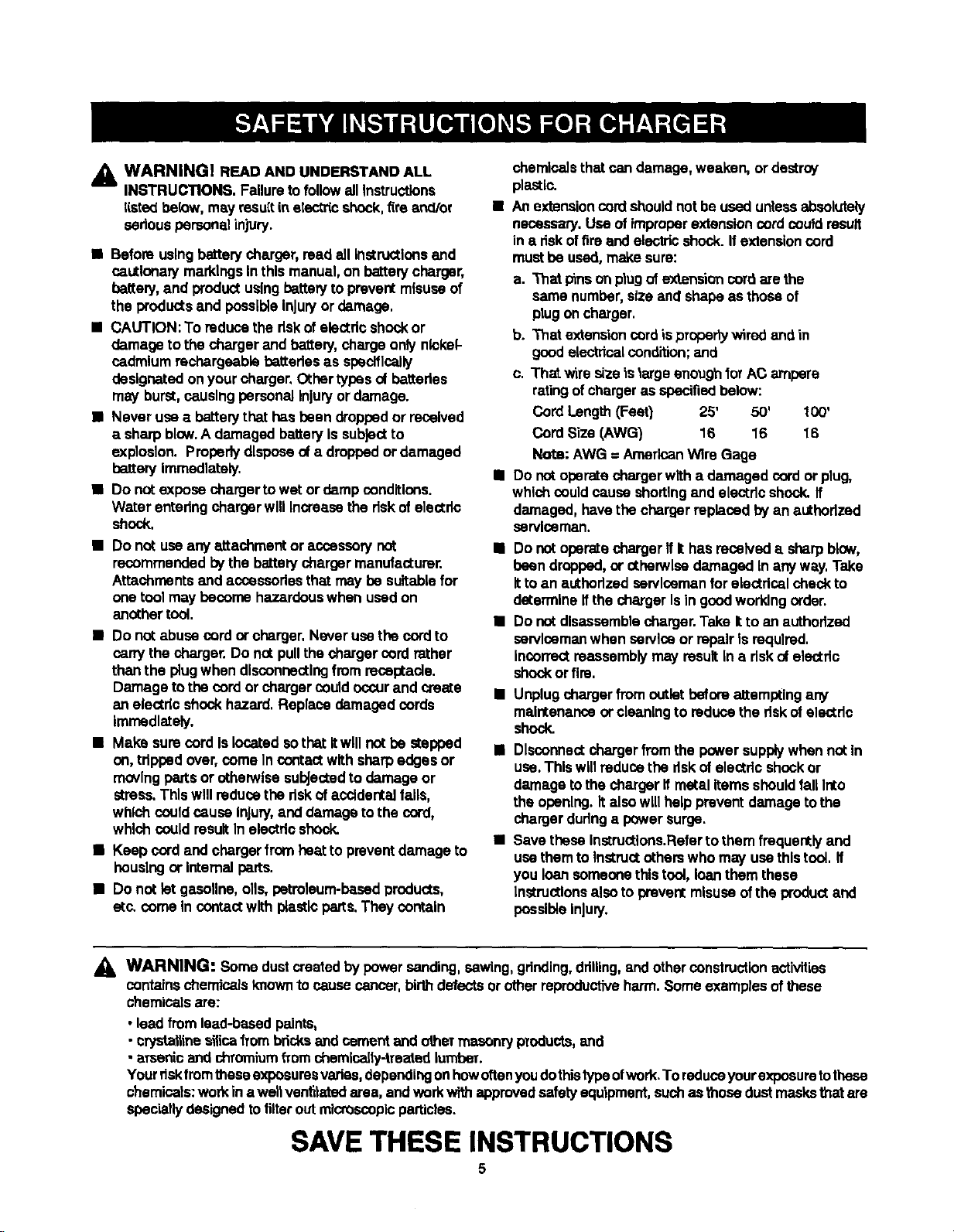
• Before usingbattery charger,read all instructionsand
nautlonary markingsInthis manual, on batterycharger,
battery,and productusingbatteryto preventmisuseof
the products and possibleInjuryor damage.
• CAUTION: To reducethe dskof electdcshockor
damage to the charger and battery, chargeonly nickel-
cadmiumrechargeable battedasas specifically
designatedonyour charger, Othertypesof batteries
may burst,causingpersonalInjuryor damage.
• Never use a batterythat has been droppedor received
a sharp blow.A damaged batteryIs subjectto
explosion. Propertydisposeof a droppedor damaged
battery Immediately.
• Do notexpose charger to wet ordamp conditions.
Water enteringcharger will Increasethe riskof electde
shock.
• Do not use any attachment oraccessorynot
recommendedby the batery charger manufacturer.
Attachmentsand accessoriesthat may be suitablefor
one tool may become hazardouswhen used on
another tool.
• Do not abuse cord or charger.Never usethe cordto
carrythe charger. Do not pullthe charger cord rather
than the plugwhen disconnectingfrom receptacle.
Damage to the onrd or charger couldoccurand create
an electdc shockhazard. Replace damaged cords
Immadlately.
• Make sure cordis locatedsothat Itwill not be stepped
on,tripped over, come Incontactwith sharpedges or
movingpartsor otherwise subjectedto damage or
stress. Thiswill reducethe dskof accidentalfalls,
which couldcause injury,and damage tothe cord,
whiohcouldresultIn electricshock.
• Keep cord and charger fromheat to prevent damage to
housingor internal perts.
• Do not letgesollne,oils, petroleum-based products,
etc. come Incontactwith plastic parts.They contain
chemicals that can damage,weaken, or dastmy
plastic.
• An extensioncordshouldnotbe used unlessabsolutely
necassa_. Use of improperextensioncordcould result
in e dskoffire and electricshock. If extensioncord
must be used,make sure:
a. "Thatpinson p|ugof extensioncord are the
same number,size and shape as those of
plugoncharger.
b. That extensioncord isproperly wired and in
goodelectricalcondition; and
c. That wire size is large enough forAC ampere
ratingofchargeras spec'd'ledbelow:
Cord Length(Feet) 25' 50' 100'
CordSize (AWG) 16 16 16
Note: AWG = AmericanWire Gage
• Do notoperate charger with a damaged cordor plug,
whichcould cause shortingand electdc shock, ff
damaged, have the chargerreplaced byan authorized
serviceman.
• Do not operatecharger ff It has receiveda sharpblow,
been dropped, or otbe_vlse damaged In any way. Take
Itto an authorizedservicemanforelectrisalcheck to
determine ffthe charger Is In goodworkingorder.
• Do not disassemblecharger.Take Itto an authorized
serviceman when service or repair Is required.
Incorrectreassemblymay resultIn a riskcAelectdc
shockor firs.
• Unplugcharger fromoutletbeforeattemptingany
maintenanceor cleaningto reducethe riskof electdc
shock.
• Disconnectcharger fromthe powersupplywhen not In
use.Thiswill reducethe riskofelectric shockor
damage to the charger ff metal itemsshouldfall Into
the opening.It also will help preventdamage to the
charger dudnga powersurge.
• Save these Instructions.Refertothem frequently and
usethem to Instructothers who may usethistool. ff
you loan someonethis tool,loan them these
Instructionsalsoto prevent misuse of the product and
possibleInjury.
_, WARNING: Some dustcreatedby powersanding,sawing, grinding,drilling,and other constructionactivities
contains chemicals knownto cause cancer,birthdefectsorotherreproductiveharm.Someexamples ofthese
chemicalsare:
• lead from lead-bssedpaints,
• crysta,ine e_Scafrombdcksand cement and other masonryproducts,and
• aTsenioand chromiumfrom chemica[ly-treated lumbar.
Yourriskfromtheseexposuresvedes,dependingonhowoftenyoudothistypeofwork.To reduceyourexposuretothese
chemicals: workin aweltventilatedarea, andwork withapprovedsafetyequipment,suchas thosedustmasks that are
speciallydesignedto filterout microscopicparticles.
SAVE THESE INSTRUCTIONS
Page 6
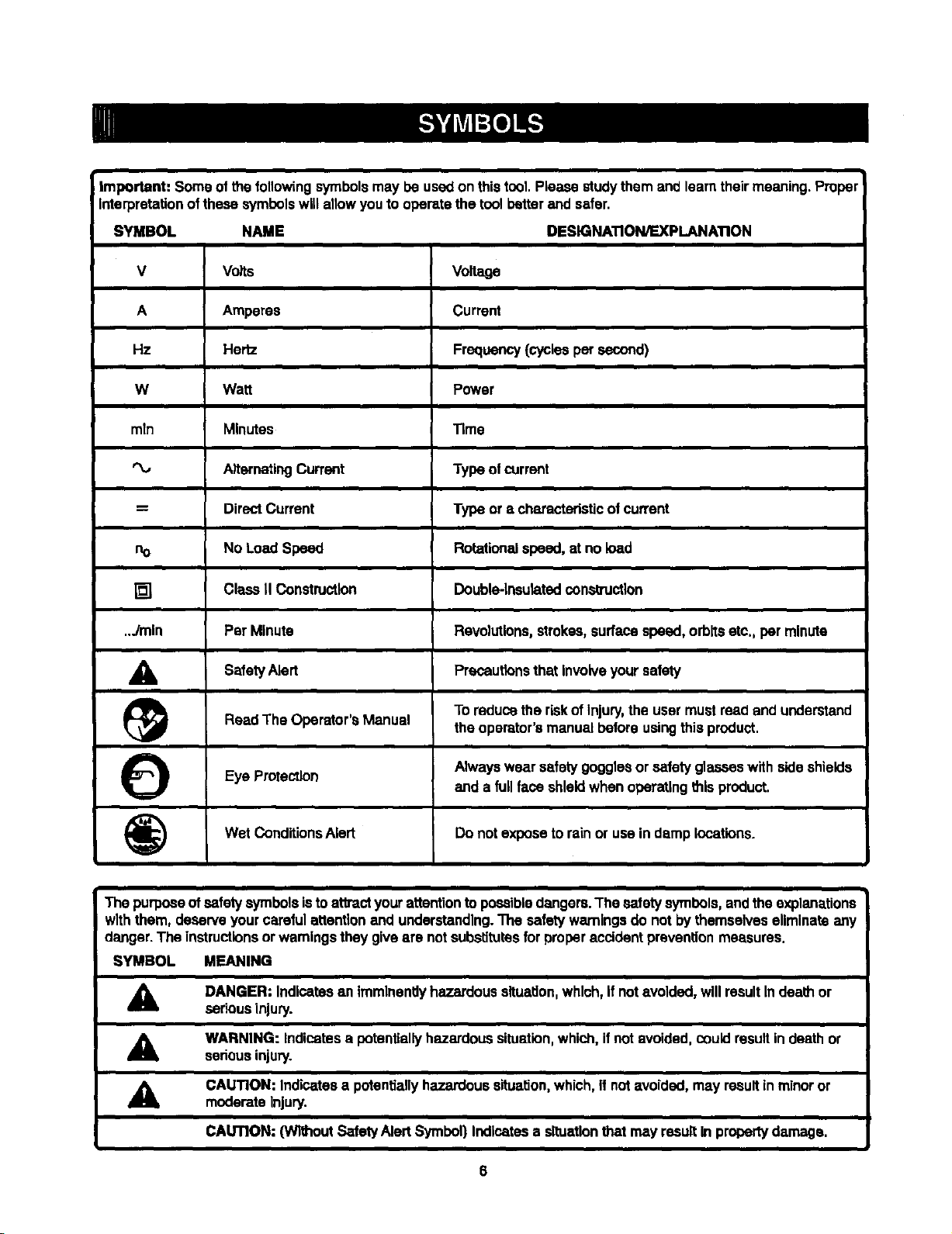
i Important: Some of the followingsymbolsmay be usedonthis tool.Please studythem and learntheirmeaning.Proper
Interpretationofthese symbolswillallowyou tooperatethe toolbetterand safer.
SYMBOL NAME DESIGNATION/EXPLANATION
V Volts Voltage
A Amperes Current
Hz Hertz Frequency(cyctesper second)
W Watt Power
mln Minutes Time
AlternatingCurrent Type of currant
= Direct Current Type or a characteristicof current
no NoLoad Speed Rotationalspeed, at no load
[] Class II Construction Double-insulatedoonsmJctlon
..Jmln Per Minute Revolutions,strokes,surfacespeed,orbitsetc., per minute
_lb SafetyAlert Precautionsthat Involve safety
(_ To reduce the riskofInjury,the usermust read and understandReadThe Operator'sManual theoperator'smanual before usingthis product.
Eye
Protection Alwayswearsafety gogglesor safety glasseswith sideshields
(_) Wet Dondltions Alert Do not torain or use in locations.
The purposeofsafetysymbolsistoat'l_ct yourattentionto possibledangers.The safetysymbols, andthe explanations
withthem, deserveyour careful attentionand understanding.The safetywarningsdo notby themselves eliminateany
danger.The instructionsorwarningstheygive are notsubstitutesforproberacddent preventionmeasures.
SYMBOL MEANING
A
A
A
DANGER: Indicatesan ImminentlyhazardoussltualJon,which,ifnot avoided,willresultIn deathor
seriousinjury.
WARNING: Indicatesa potentiallyhazardoussituation,which,if notavoided,cuuid resultin death or
seriousinjury.
CAUTION: Indicatesa potentiallyhazardoussituation, wh|ch,ifnotavoided,may result inminor or
moderateInjury.
and a fullface shieldwhen operatingthisproduct.
expose damp
your
CAUTION: (W_'mut SafetyAlertSymbol)Indicatesa situationthatmay resultIn propertydamage.
Page 7
PRODUCTSPECIFICATIONS
Chuck........................................... 3/8 in. (10 ram)Keyless
Motor.............................................................. 14.4 Volt DC
Switch ....................................................... Vadab[e Speed
Gear Train ............................................................. 1 Speed
No Load Speed ................................................. 0-6501min.
C[utoh............................................................... 4 Positions
Charger input........................_........ 120 V. 60 Hz, AC only
Charge Rate ....................................................... 3-6 Hours
Torque.................................................................... 90 In.lb.
KNOW YOUR DRILL-DRIVER
See Figure 1,
Beforeattempting to use your ddll-ddver,familiarize
yourselfwith alloperatingfeatures and safety
requirements.
WARNING: Carefully read throughttdsentire
operator'smanual before usingyour new dhlt-dr'rvar.
Pay closeattentionto all Salety Rules, Warningsand
Cautions. It you use yourdrill-driverpropertyand
onlyforwhat itIs Intended,you willenjoy years of
safe, reliableservice.
,_ WARN|NG: Do not allowJamiliaritywithyour rid}l-
driverto make you careless. Remember that a
careless tractiono1a second Is suff_em to Inflict
severeinjury.
KEYLESS CHUCK
Yourdrift-driverhasa keylesschuckthatallowsyouto hand
_ghtenor releasedrillbitinthechuckjeers.
DIRECTION OF ROTATION SELECTOR
FORWARD/REVERSE
Yourdrill-driverhasa forward/reverseselectorlocated
above t_e sw}tchtrigger.The sw_chtdggercan be locked
intheOFF position.
SWITCH TRIGGER
Toturnyourdrill.driverON, depressthe switchtrigger.
Release switchtrigger to turnyourdrill-driverOFF.
VARIABLE SPEED
This tool has a variable speed switch that delivershigher
speed withincreasedtriggerpressure.Speed iscontrolled
bythe amount ofswitchtdggerdapmse)on.
BIT STORAGE
When not In usa, bitspro'tidedwith yourclflfl-drivarcan be
placed_ the storage area locatedon the top ofthe motor
housing.
TORQUE ADJUSTMENT RING
Yourdrill Is equippedwith an adjustabletorquerk'vgfor
drivingdifferenttybes ofscrewsintod_farentrnaterials.
The proper settingdependson the type of materialand
the size of the screw you are using.
Page 8

TORQUE
ADJUSTMENTRING
KEYLES8
CHUCK
CHARQER
ASSEMBLY
BAI-rERY
INSTRUCTIONS
When unpackingthe tool:
• Carefully removethe tool andaccassodesfromthe box.
• Make surethatall items listedin the packing listare in-
cluded.
• Inspect the tool carefullyto make sure no breakage or
damage occurredduringshipping.
• Do notdiscardthe packing material untilyou havecare-
fully inspectedand satisfactorilyoperatedthe tool.
• If any parts are damaged or missing,pleasecall
1-800.932-3188 for assistance,
BIT
STORAGE
ROTATIONSELECTOR
(FORWARD/REVERSE)
TRIGOER
Fig. 1
PACKING LIST
3/8 in, (10 mm)Drill-Driver
ChargerAssembly
BatteryPack
Double-endedBit(2)
Operator'sManual
Case
,_ WARNING; Ifany parts are missing do not operate
the tooluntilthe missingparts are replaced.Failureto
do so coukiresultin possiblesedouspersonal injury.
8
Page 9

WARNING:Donot allow familiaritywithyourdrill-
df',verto make you careless.Remember that a
carelessfraction of a secondis sufficientto _nffict
severe Injury.
CHARGING YOUR DRILL-DRIVER
The battery packforthis tool has beenshippedIn e low
charge condition to preventpassible problems.Therefore,
you should chargeItat least 6 hourspdorto use.
Kote: Batterieswillnot reach furlchargethe firsttime they
are charged.Atlowseveral cycles (drillingtoltowedby
recharging)forthem to tullycharge.
• Charge batterypack onlywiththechargingassembly
provided.
[] Make sure power supply Is normal house voltage,
120 Volts, 60 Hz, AC only.
• Connectchargingassembly to power supply.
• Place batterypack In chargingassembly.Align raised
ribon battery pack withgroovein chargingassembly.
See Figure 2.
• Press downon batterypack to be sure contactson
batterypack engage properlywithcontacts incharg-
ingassembly, When pmpedy connected, red lightwill
turn on and remainon untilbatteryis removedor
chargeris unplugged.
• After normalusage, 3 hoursof chargingtime is
required to be tully charged. A minimumcharge time
of6 hours is requiredto rechargea completely
dischargedbattery.
• The batterypackwill becomeslightlywarm tothe
touchwhile charging.This isnormaland does not
indicatea problem.
• DO NOT place chargingassemblyin an ares of
extreme heat orcold. It willwork bestat temperatures
between 50°F-100°F.
TO INSTALL BAI"I'ERY PACK
• LockswitchIdggar on your drillby placingthedirection
of ro_a'_onselectorin centerposition.Sea F')gure3.
• Place file batterypack inyour drill.Align raised ribon
batterypackwithgroovein drill'sbattery pert.
See Figure 4.
• MBJCesurethe _tches on each sideof your battery
pack snap in place and thatbatterypack issecuredin
ddtibefore beginningoperation.
DIRECTIONOF
FLOTATIONSELECTOR
(i
CENTERPosmoN
(LOCiO swrrcH'reuG
Fig. 3
TO REMOVE BAT'rERY PACK
• Lockswit_ tr(ggaron your drillbyplacing thedirection
of rotationselector incenter pealtion. See Figure3.
II Looatelatchesonsldeofbatterypeckanddeprsesboth
sidestoreleasebatterypack[mmyourdrilLSee Figure6.
• Remove batterypackfromyourddti.
CAUTION: When placingbattery pack inyourdritl,
be sure raised db on batterypeck alignswithgroove
in ddll"Bbatterypert and latchessnap in place
properly.Improperassemblyof battery pack can
cause damage to internalcomponents.
CHARGE
INDICATOR
LIGHT(teD)
,ASSEMBLY
F_g.2
9
Page 10

BATrERT
PACK
BATrlERY
PORT
DEPRESSLATCHESTO
RELEASEBATTERYPACK
F'_.4
SWITCH
See Figure 5.
Your ddi]starts and stopsby depressingand releasingthe
switchtrigger.Release the switchbigger toturnddllOFF.
VARIABLE SPEED
See Figure 5.
Your ddll has a variable speed feature in the switch.The
switch delivem higher speed and torque with increased
tdgger pressure. Speed is controlled by the amount of
switchtriggerdepression.
SWITCH LOCK
See Figure 5.
The switchtriggercan be locked In the OFF position.This
feature helps reduce the possibilityof accidental starting
when notInuse.Tolocktheswitchtrigger,placethe direct'on
of rotationselector in thecenter position.
REVERSIBLE
See Figure 5.
This tool is reversible.The directionof rotationiscontrolled
bya selector locatedabovethe switchtdgger.Withthe drill
held in normaloperating position,the directionof rotation
selector shouldbe positionedto the left of the switchfor
drilling.Theddflingdirectionisreversedwhen theselector is
to the right of the switch. When the selector Is In center
position, the switchtriggerislocked.
CAUTION: Topreventgear damage,alwaysallowchuck
tocome toa completestopbefore changing the directionof
rotat|on.
To stop,release switchtriggerand allow the chuckto come
toa completestop.
_1= WARNING: Battery tools ere always in operating
cond_on. Therefore, switchshould always be locked
when notIn use orwhen cerwIng at your side.
DIRECTIONOF
ROTAllONSELECTOR
(FORWARD/ REVERSE)
REVERSE
!
CENTERPOSITION
(lOCK) SWITCHTRIGGER
KEYLESS CHUCK
See Figure 6.
Akeylasschuckhasbeen providedwithyourddllto allowfor
eas_JIr_mJlatton and ramoval ot b_ts.Asthe name '_las,
youcan hand tighten or releasedrillbitsinthe chuckjaws.
Graspandholdthecollar ofthechuckwithonehand.Rotate
the chuck body with your other hand. The arrows on the
chuck indicatewhich directionto rotate the chuck body in
orderto GRIP (_ghten)or RELEASE (ur_ck) the ddll bit.
,_ WARNING: Do not hold _ chuck body withone
hand and use the power ot the drill to tightenchuck
jawson drillbits.Chuck bodycouldslipinyourhand
or your hand could slip and coma In contact with
rotatingddit bit.This could causeanaccidentrasu_ng
in sedouspersonalinjury.
RELEASE
(UNLOCK) KEYI.ESS
BIT
GRip
(TIGHTEN)
CHUCK
COLLAR
tO
FORWARD
CHUCK
Fig. 6
Fig.5
Page 11

SCREW'DRIVING
TORQUE ADJUSTMENT
(Driving power of your drill-driver)
When using your drill-driverforvarlous drivingapplica-
tions,itbecomes necessaryto increase or decrease the
torquein orderto help prevent the possibilityofdamaging
screwheads, threads,workplace, etc. In general, torque
shouldcorrespondto the intensityof the screwdiameter.
Ifthe torque istoo highor the screwstoo small,the
screws may be damaged or broken.
The torque "isadjustedby rotatingthe torque adjustment
ring.See Figure7. The torqueis greaterwhen the torque
adjustmentringis set on ahighersetting. The torqueis
lesswhen the torque adjustmentdng Isset ona lower
setting.
The propersettingdependson the type of materialand the
size of screw youare using.
TO ADJUST TORQUE
Identify the four torque Indicator settingslocated on
the fi'ontof your drill.See Figure7.
Rotate adjustmentringto the desiredset'ring.
• Position_: For ddvingsmallscrews.
• Pos_on 2: Forddvlngscrews Intosoftmaterial.
• Pos_on3: Fordrivingscrews into hard wood.
41,_1 ForheavyddUing.
BIT STORAGE
See Figure 8.
When not in use, bitsprovidedwithyour drillcan be
placedInthe storagearea locatedon the topof yourdrill
as shownin figure 8.
BIT
STORAGE
Fig. B
TODECREASE TORQUE
TORQUE /LJ),IUS'INENTRING
Fig. 7
11
Page 12

INSTALLING BITS
• Place thedirectionofrotationcelector incenterposition.
See Figure 5. This will turnoffthe powertoyourdrill.
• Open or close the chuck jaws to a point where the
opening is slightlylargerthan the bitsize you intendto
use. Also,raisethe frontofyourdrillslightlyto keep the
bitfrom fallingout ofthe chuckjaws.
• lnsert your dntl bit intothe chuck the full lengthof the
Jaws.See Figure9.
RELEASE
(UNLOCK)
GRIP
(TIGHTEN)
CHUCKCOLLAR
• Tighten thechuck)awson thedrillbit.To tighten,grasp
and hold the collar of the chuckwith one hand, while
rotatingthe chuck bodywithyourotherhand.
Note: Rotatethe chuckbodyinthedirectionof thearrow
marked GRIP to tightenthe chucklaws.
• DO NOT use a wrench to tighten or loosen the chuck
laWS.
CHUCKBODY
Fig. 9
Fig. 10
REMOVING BITS
See Figure2.
• Place the directionof rotation selectorIncenter
posit_on.See Figure3. Thiswillturn off the power to
yourddlL
• Loocenthe chuck.jawsfromdfitlbit.
• To loosen:grasp and holdthe cellar of the chuckwl_
one hand, whi_erotatingchuckbodywithyour other
hand.
Note: Rotatechuckbodyinthe directionof the arrow
marked RELEASE to _oosanchuckjaws.
• DO NOT uses wrenchtotightenor loosenthe chuck
jews.
• Remove ddllbitfrom chuck Jaws.
A WARNING: Do notinsertdrillbitintochuckjaws
and tightenas shown in Rgure 10. Thiscouldcause
drtUt_t tobe thrown_mmddt_rasu_ng inpasstbls
serious personalinjuryordamage to the chuck.
12
Page 13

_1= WARNING: Always wearsafety gogglesor safety
glasseswith side shields whenoperatingtool,
Failureto do so couldresult inobjectsbeing thrown
intoyour eyes, resultingin possibleseriousinjury,
DRILLING
See Figure 11.
When drillinghard, smooth surfaces, usa a canterpunch
to markthe desiredhole Iocallon.Thiswff!preventthe ddl[
bitfrom slippingoffcanter as the hole is started. How-
ever, the lower speedfeature allowsstartingholeswithout
canter punchingifdesired.To accomplishthis, simply
operate yourdrillat lower speed untilthe hole Is started.
The matedsi to be ddlied shouldbe secured in a vise or
with clamp_to keep It fromturningas the drillbIt rotates.
Holdtoolfirmly and place the bitat the pointtobe drilled.
Depressthe switchtriggerto start tool.
Move the drillbit into the workpieca,applyingonlyenough
pressureto keepthe bitcutting. Do notforce or applyside
pressureto elongatea hole.
_= WARNING: Be prapaTedfor bindingor bit
breakthrough,When these situationsoccur,the drill
has a tendency to grab and kickoppositeto the
directionof rotationand couldcause toss of control
when breaking throughmaterial, if you are not
prepared, thislossof controlcan result in possible
sedousinjury.
When drillingmetals, use a light oil on the drillbitto keep
it from overheating.The oilwillprolongthe lifeofthe bit
and increasethe ddltingaction.
it the bitjams in workplaceor ifthe drillstalls,release
switchtriggerimmediately,Remove the bitfromthe
workplaceand determinethe reasonfor jamming.
Fig. 11
13
Page 14

CHUCK REMOVAL
See Figures 12 - 14.
• Lockthe swiLchtriggerbyplscingthedirectionof retation
selectorincenter position.See Figure 5.
• Insert a 5/15 inch or larger hex kay Intothe chuck of
yourddttand [_ghtenthe chuckjews sscumly.
• Tap the hax key sharply with a mallet ina clockwise
direction.See Figure 12. This will loosenthe screw In
thechuck for easy removal.
• Open chuck jaws end remove hex key, Remove the
chuckscrew byturningit In a ctuck_se direcffon.
See Figure 13.
Note: The screw has left handthreads.
• Inserthex key Inchuckend tightenchuck_ws securely.
"Tapsharp!,ywithe ma]_,a_ine counterclock_sedirection.
This will loosen chuck on the spindle, tt can now be
unscrewed by hand. See Figure14.
CHUCKJAWS
\
TO RETIGHTEN A LOOSE CHUCK
The chuckmay become iocse on spindleand develop a
wobble. Periodicallycheck the chuckscrew for tightneSs.
Totighten,followthese steps:
• Locktheswitchtriggerbypiecingthedirect_n ofrotation
selectorIncenter position. See Figure5.
• Open the chuckjaws.
• insert hex key into chuck and tighten chuck jaws
securety.Taphex keysherptywitha mallet ina clockwise
direction,This will_ightenchuckon the spindle.
[] Open the chuckJawsand removehax key.
• "Tightenthe chuckscrew.
Note: The chuck screw has lefthand threads.
Fig, 12
Fig. 13
Fig.
t4
Page 15

_lb WARNING: When servicing,useonly identical
Craftsmanreplacementperts. Useof any other pert
may create ahazard or cause productdamage.
Do not abuse powertools. Abusivepracticescandamage
toolas wall asworkplace.
,_, WARNING: Alwaysremove the battery packfrom
thetool when assemblingparts, making adiustments,
cleaningor whennot In use. Removingthe battery
peck wiltprevent accidentalsbartingthat couldcause
sedouspersonalinjury.
Use clean clothsto removedirt, carbondust, etc.
_, WARNING: Do notat any time let brakefluids,
gasoline, petroleum-basedproducts,penetraUngoils,
etc. come in contactwith ptssttcparts.They contain
chemicalsthat can damage, weaken or destroy
plastic.
Only the parts shownon parts list,page 17, are intended
to be repairedor replaced bythecustomer.Allother parts
shouldbe replaced at a Sears Service Center.
_1= WARNING: Do not attempt to mod_ this tool or
create acoessodesnot recommendedfor usewith
this tool Any such alteration or modification is
mfsuce and could result In a hazardous cona'i6on
leading to possibte serious persona[ injury.
A WARNING: Always wear safetyglasseswith side
shieldswhen usingcompressed air to cleantoots, it
the operationisdusty,also wear a dust mask.
BATTERIES
The batterypack forthe drill-driverisequipped with
nickel-cadmiumrechargeable batteries.Lengthofservice
fromeach chargingwill depend on the typeof workyou
are doing.
The batteriesin thistool have been designedtoprovide
max=mumtroublefree life. t-lowever,tike artbattaries, they
wilteventuallywear out. Do not disassemblebattery pack
and attemptto replace the batteries. Handfingofthese
batteries, especially when wearing ringsandjewelry,
could result In a seT_ousbum.
To obtainthe longestposslb(e battery life, we suggest the
following:
To preserverBtw_ resources,please
recy_e ordLsposeof batteries properly.
"Thisproductcontains n_cke_-cadmlum
batteries.Local,state or federal laws
may prohbit dispose| of nickel-cadmium
batteries in ordinarytrash.
Consultyour Ioca/waste authorityfor information
regardingavailable recyclingand/or disposaloptions,
[] Storeand chargeyourbatteries In a cool area.
Tempera_,uresbelow 50°F or above 10Q°Fw_l_shorten
batterylife.
[] Never storebattmles In a dischargedcondition.
Recharge them immediatelyafter they are
discharged.
[] All batterlesgr_du_lty losethelr chaTge..Thahlghar
thett_npersture the o_ickerthey k_sett_ir charge. If
you store yoz_rtootfor Ioogperiodsoftimewithout
using R,rechargethe batteries avery month ortwo.
Thl.spracticewill prok_ batteryIKe.
BATrERY PACK REMOVAL AND
PREPARATION FOR RECYCLING
_, WARNING: Uponremoval, cover the battery
pack'sterminals withheavy dutyadhesivetape. Do
not attempt to destroyor disassemblebatterypeck
or remove any of its components.Nickel..cadm(um
batteries mustbe recycledor disposedof properly.
Also, never touchboth terminaJswith metalobjects
and/or bodyparts as short c/muifmay result.Keep
away fromohltdren,Failure to comply withthese
wam_ngscould result"mfire and/or serious'injury.
15
Page 16

16
Page 17

COMPANION 14.4 VOLT CORDLESS DRILL
MODEL NO, 315.101860
I The model number will be found on a plate attached to the motorhousing. Always mentionthe model ]numberin all correspondenceregardingyourCORDLESS DRILL-DRIVER or when orderingrepairparts,
SEE BACK PAGE FOR PARTS ORDERING INSTRUCTIONS
2
1
Key PaR
No, Number
1 660120O01
2 690033022
3 130122041
4 140209O23
580013004
983000-409
4
PARTS LIST
Description Qty,
Screw .................................................................................................. 1
Chuck .................................................................................................. 1
Battery pack ........................................................................................ 1
Charger ............................................................................................... 1
Carrying Case (not shown) ................................................................. 1
Operator's Manual
17
Page 18

COMPANION 3/8 In. 14.4VOLT CORDLESS DRILL-DRIVER - MODEL NUMBER 315.101860
14
15
13
10
%, : 9
11
P 12 _ 14\
8
7
6
5
3 4
2
1
Page 19

COMPANION 3/8 In. 14.4 VOLT CORDLESS DRILL-DRIVER - MODEL NUMBER 315.101860
CORDLESS DRILL-DRIVER or when orderingrepair parts.
The model numberwill be found on a plateattachedto re motorhousing.Alwaysmentionthe modelnumber In allcorrespondenceregarding your |
PARTS LIST
|
J
KEY PART
NO. NUMBER
1 6620501
2 6320801
3 6722101
4 5267710
5 6759001
6 3656302
7 6320701
8 5267511
9 680095001
10 5369701
11 5260411
12 6711101
13 6710501
14 200202154
15 67_'_001
16 985348-001
17 270018018
18 66206O6
19 6620614
983000-409
983000-409R
12-04-03
DESCRIPTION QTY.
* SCREW (M3 X 14 mm)................................................................................................................ 4
MOUNTING PLATE..................................................................................................................... 1
BALL,,,,,,.*,,,*,,*,*.,*,*,*,*,**,,,,***,*.**,,,,,, ................ *.**.*,,*,*.*,,,,*,*,*,*,,, ....................... *.*...*,,,*.,,*,,,,,,,,,,., 6
BALL HOLDER ............................................................................................................................ 1
WASHER .................................................................................................................................... 1
CLUTCH CAP.............................................................................................................................. 1
SPRING PLATE........................................................................................................................... 2
SLEEVE ....................................................................................................................................... 1
SPRING ....................................................................................................................................... 1
DETENT RING ............................................................................................................................ 1
BIT CLIP ...................................................................................................................................... 1
WASHER ..................................................................................................................................... 1
CLUTCH WASHER ...................................................................................................................... 1
HOUSING ASSEMBLY................................................................................................................ 1
BALL.......................................................................................................................................... 16
MOTOR AND GEAR TRAIN ASSEMBLY.................................................................................... 1
SWITCH ASSEMBLY................................................................................................................... 1
* SCREW (M3.5 X 16 mm)............................................................................................................. 6
* SCREW (M3.5 X 14 mm) ............................................................................................................. 2
OPERATORS MANUAL
REPAIR SHEET
* STANDARD HARDWARE ITEM - MAYBE PURCHASED LOCALLY.
Page 20

COMPANION 3/8 In. 14.4 VOLT CORDLESS DRILL-DRIVER - MODEL NUMBER 315.101860
BLUE LEAD
RED LEAD
HEAT SINK
BLACK LEAD
BLACK LEAD
RED
BLACK LEAD
WIRING DIAGRAM
Page 21

Your Home
For repair-in your home-of all majorbrand appliances,
lawn and garden equipment, or heating and coolingsystems,
no matter who made it, no matter who sold it]
For the replacement parts, accessories and
owner's manuals that you need to do-it-yourself.
For Sears professionalinstallationof home appliances
and items like garage door openers and water heaters.
1-800-4-MY-HOME ® (l-eoo-4se-4s63)
Call anyUme, day or night(U.S.A. and Canada)
www.sears.com www.sears.ca
Our Home
For repair of carry-in items likevacuums, lawn equipment,
and electronics, call or go on-line for the Ioca_onof your nearest
Sears Parts & Repair Center.
1-800-488-1222
Call anytime, day or night (U.S.A. only)
www,sears.€om
To purchase a protectionagreement (U.S.A.)
or maintenance agreement (Canada) on a product serviced by Sears:
1-800-827-6655 (U.S,A.) 1-800-361-6665 (Canada)
Para pedir servicio de reparacibn Au Canada pour service en fran_ais:
a domicilio, y para ordenar plazas: 1.800.LE.FOYERaC
1-888-SU-HOGAR s" (1-800-533-6937)
(1-888-784.5427) www.sears.ca
8EAFR8
® RegiuteredTrademarkI _ Trademlrk / su_wl_ Mark o(Seara, Roebud,,andCo.
® MarneRegl_rada I xa Maroade Fibdca I m MerGede _dd o de 8earzz,p_ _ _.
uc Mre'quade commerceI MDMarqued6pos6edeSeallk Roebud_andC_ ® _, Roebuckmd Co.
 Loading...