

Page 1

File: SHC-100 User manual(Eng)_V0.7 (LT
Edit).docx
Date: 2018/07/16
Version: 0.7
Page: 8
isopropylique ou de 70% d'alcool éthylique.
SHC-100
Ne pas immerger ou rincer le SHC ou ses périphériques. Si vous renversez
accidentellement du liquide sur l'appareil, déconnectez l'appareil de la source
d'alimentation. Contactez votre service Biomed en ce qui concerne la sécurité
continue de l'unité avant de la remettre en service.
Ne pulvérisez pas de produit de nettoyage sur le châssis.
N'utilisez pas de désinfectants contenant du phénol. Ne pas autoclaver ou nettoyer
le SHC ou ses périphériques avec des solvants forts aromatiques, chlorés,
cétoniques, éthers ou Esther, des outils tranchants ou des abrasifs. Ne plongez
jamais les connecteurs électriques dans l'eau ou d'autres liquides.
Ne rayez pas la surface de l'écran avec des objets durs.
Ne vaporisez pas de liquide directement sur l'écran ou laissez l'excès de liquide
s'égoutter dans l'appareil.
Ne placez aucun objet, tel que de la nourriture et des boissons, sur l'écran à tout
moment pour éviter d'endommager l'écran.
Nettoyez l'écran LCD uniquement avec un chiffon doux imbibé de 70% d'alcool
Page 2

File: SHC-100 User manual(Eng)_V0.7 (LT
Edit).docx
Date: 2018/07/16
Version: 0.7
Page: 9
SHC-100
1.6 I
NTENDED USER PROFILE
Age: 25 - 60
Weight: Not relevant
Health: Not relevant
Nationality: Not relevant
Patient state: The patient will be the operator
Part of the body or type of tissue applied to or interacted with: Hands and fingers, expected
contact time shall be less than 1 min.
Education level: At least 8 years of intensive reading experience (school)
Knowledge:
Minimum – Can read and understand “westernized Arabic” numerals when written in Arial font
– Can distinguish every part of the body as described in the user manual
– Understands the potential risks and hazards regarding misjudgment of diagnostic images.
Language understanding: English or Chinese
Experience: Mentally and physically competent, specific medical training to read medical images
and to have a basic understanding of symbols.
Permissible impairments:
– Mild reading vision impairment or vision corrected to log MAR 0,2 (6/10 or 20/32)
– One arm/hand capable of guiding and holding the device
– An average degree of aging-related short-term memory impairment
– Hearing impairment of 40 % resulting in 60 % of normal hearing levels at 500 Hz to 2 kHz
Operating Principle:
A computer processing system panel with the following main components: the arithmetic logic unit
(ALU), the control unit, the memory, and the input and output devices (collectively termed I/O).
These parts are interconnected by buses, the control unit, ALU, and registers are collectively known
as a central processing unit (CPU), the unit processes and delivers patients electronic information to
an internal touchscreen.
Page 3

File: SHC-100 User manual(Eng)_V0.7 (LT
Edit).docx
Date: 2018/07/16
Version: 0.7
Page: 10
Environment:
– General Requirements:
• Hospital or clinics, professional healthcare personnel use only.
• Indoor use only
• Not for use in the shower, bathtub, or sink
• The display is to be placed on a desk.
– Expected to function normally
– Conditions of visibility:
• Ambient luminance range: 100 lux to 1,500 lux
• Viewing distance: 20 cm to 40 cm
SHC-100
• Viewing angle: Normal to the display ± 45°
– Physical:
• Temperature range: 0°C to 40 °C
• Relative humidity range: 10 % to 90 %, non-condensing
• Relative altitude range: 0 to 3000m
The frequency of use: 1 to 10 times a day.
Mobility:
– Fixed MEDICAL DEVICE to be used beside a resting PATIENT.
– Fixed MEDICAL DEVICE to be used on a nursing cart.
Quality related risks are considered in FMEA (doc no. EFH00-PM-004), quality-related risks
are not considered as a result of harm; therefore risk evaluation only lists those which may cause
harm to the user.
Page 4
File: SHC-100 User manual(Eng)_V0.7 (LT
Edit).docx
Date: 2018/07/16
Version: 0.7
Page: 11
Intel® Core™ i5 7200U, 2.5GHz Processor, KBL
Intel® Core™ i5 7300U, 2.6GHz Processor, KBL
Memory
4G DDR4 SODIMM 2133/2666MHz (up to 32G)
Storage
500G HDD (Optional: SSD)
Camera
8 Megapixel
Graphic Chip
Intel® HD Graphics
Trusted Platform Module (TPM2.0) &
Wake-on-LAN/WiFi
Bus Expansion
M.2
Size
21.5” (54.6cm), 16:9
Max Resolution
Full HD 1920x1080
Brightness
LED backlight, 250 nits
Contrast
1000:1
Cleaned by Disinfectant
Isopropyl alcohol 70%, Ethyl alcohol 70%
Type
Capacitive Touch (Multi-touch:10)
Light Transmission
95%
Durability
30 million touches
Surgical Glove Friendly
Need
USB Port
Rear: USB3.0*1+USB2.0*3, Side:USB2.0*1
1(included in USB ports, support Skype for
Business )
NFC/RFID
1 (support 14443A、14443B、SRIX4K)
HDMI out
1
Earphone/Microphone
1 (Combo audio jack)
COM Port
1 (RS-232)
Smart Card Reader
1
Card Reader(3合1)
1
Speaker
3 W x 2
Microphone
1 (Integrated)
LAN
10/100/1000/Gigabits Mbps RJ-45
WLAN
802.11 a/b/g/n/ac
WiFi antenna
integrated or external
Bluetooth
BT 4.1
Bus
Expansion
Platform
Operating System
Win10
Chapter 2 Hardware Description
SHC-100
2.1 S
Hardware
Display
Touchscreen
PECIFICATIONS
CPU
Chip Set
Support Intel®
I/O
Audio
Network
Microphone in
Mini-PCIe 1
Page 5
File: SHC-100 User manual(Eng)_V0.7 (LT
Edit).docx
Date: 2018/07/16
Version: 0.7
Page: 12
Mounting
VESA 100*100 & 75*75 mm
Dimensions ( W x H x D)
535.2 x 375.7 x 50.4 mm
Weight
6.3 kg (with stand: 8.5 kg)
SSD
256G
accessory port
ODD/ COM2+ USB2.0*3
Hand Set Holder
Optional (support Skype for Business )
Supply
Input Voltage
100 - 250 Vac, 1.5 - 0.75 A, @ 50 - 60 Hz
Output
19 VDC, 3.15A
Cooling System
Fanless
Operating Temperature
0 - 40° C
Storage/transportation
Temperature
Operating Humidity
10% - 90% (No Condensation)
Storage/transportation
Humidity
Operating Altitude
700 - 1060 hPa
Storage/transportation
Altitude
LED indicator
White = turn on
Vibration
1 G
Shock
10 G
approved, UL 60950, UL 62368, RoHS, CCC, CEL
Mechanical
Options
Power
-20 - 60° C
SHC-100
Environment
Certifications
10% - 90% (No Condensation)
500 - 1060 hPa
BSMI, CE,FCC Class B approval, IEC/ANSI60601-1
Page 6

File: SHC-100 User manual(Eng)_V0.7 (LT
Edit).docx
Date: 2018/07/16
Version: 0.7
Page: 13
SHC-100
2.2 E
2.2.1 Front View
XTERNAL VIEW
Figure 2.2.1-1 Front View
2.2.2 Side View
Figure 2.2.2-1 Side View
Page 7

File: SHC-100 User manual(Eng)_V0.7 (LT
Edit).docx
Date: 2018/07/16
Version: 0.7
Page: 14
2.2.3 Rear View
SHC-100
Figure 2.2.3-1 Rear View
Page 8

File: SHC-100 User manual(Eng)_V0.7 (LT
Edit).docx
Date: 2018/07/16
Version: 0.7
Page: 15
Warning!
The SHC-100 is supplied by a 60 Watt power supply and a special adapter as depicted
for the mode abovel.
If a medical adaptor is connected to the
regulatory compliance and that
requirements of this hardware.
Le SHC
que représenté pour le modèle ci
Si un adaptateur médical est connecté
conformité légale et réglementaire et que l'appareil répond aux exigences légales et aux
exigences de conformité de ce matériel.
Step 1
Step 2
Step 3
Chapter 3 Installation
SHC-100
3.1 I
NSTALLATION PROCEDURES
3.1.1 Connecting the Power Cord
The SHC-100 should only be powered by a DC power adapter (DELTA MDS-060AAS19 B).
Be sure to always handle the power cords by holding the plug ends only.
Follow these procedures sequentially:
1. Connect the female end of the power adapter to the DC-in power port of the PC. (See Figure
3.1.1-1)
2. Connect the female end of the power cord to the DC power adapter.
3. Connect the 3-pin male plug of the power cord to an electrical outlet.
Figure 3.1.1-1Connecting the power
Avertissement!
-100 est alimenté par une alimentation de 60 watts et un adaptateur spécial tel
SHC-100, the customer must ensure legal and
the device meets the law and standards compliance
-dessus.
au SHC-100, le client doit s'assurer de la
Page 9

File: SHC-100 User manual(Eng)_V0.7 (LT
Edit).docx
Date: 2018/07/16
Version: 0.7
Page: 16
3.1.2 Switching on the power
Push down the power button on the front panel of the SHC-100. (The color of the indicator
will turn white)
SHC-100
Page 10

File: SHC-100 User manual(Eng)_V0.7 (LT
Edit).docx
Date: 2018/07/16
Version: 0.7
Page: 17
Note!
Some distributors and system integrators may have already preinstalled system software
prior to shipment of your PC.
SHC-100
3.2 R
3.3 I
UNNING THE
Your SHC-100 is likely to have been properly set up and configured by your dealer prior to
delivery. You may still find it necessary to use the BIOS (Basic Input-Output System) setup program
to change system configuration information, such as the current date and time or your type of hard
drive. The setup program is stored in read-only memory. It can be accessed either when you turn on
or reset the panel PC, by pressing the " F1 " key on your keyboard immediately after powering on
the computer.
The settings you specify with the setup program are recorded in a special area of memory called
CMOS RAM. This memory is backed up by a battery so that it will not be erased when you turn off
or reset the system. Whenever you turn on the power, the system reads the settings stored in CMOS
RAM and compares them to the equipment check conducted during the power on self-test (POST). If
an error occurs, an error message will be displayed on the screen, and you will be prompted to run
the setup program.
NSTALLING SYSTEM SOFTWARE
BIOS S
ETUP PROGRAM
Recent releases of operating systems from major vendors include a setup program which loads
automatically and guides you through hard disk preparation and operating system installation. The
guidelines below will help you determine the steps necessary to install your operating system on the
PC’s hard drive.
Remarque!
If required, insert your operating system's installation or setup diskette into the external diskette
drive until the release button pops out.
The BIOS supports system boot-up directly from the CD-ROM drive. You may also insert your
system installation CD-ROM disk into your external CD-ROM drive. Power on or reset the system
and then enter the BIOS menu by pressing the “F1” key. And adjust the boot device sequence.
Or you can press “F12” key when booting, a bootable device popup menu will appear, you can
then select the bootable device that you want. The SHC terminal will automatically load the
operating system from the USB disk or CD-ROM. If you are presented with the opening screen of a
setup or installation program, follow the instructions on the screen. The setup program will guide
you through the preparation of your hard drive, and installation of the operating system.
Page 11

File: SHC-100 User manual(Eng)_V0.7 (LT
Edit).docx
Date: 2018/07/16
Version: 0.7
Page: 18
Warning!
Be sure to secure the screws of the mounting bracket tightly. A loose joint between the
SHC
Assurez
100 et le support de montage peut créer un risque de blessure.
SHC-100
3.4 I
NSTALL
integrate the PC into their system.
100. VESA mount installation should be carried out by a professional technician; please contact a
service technician or your retailer if you need mounting service.
Installation instructions:
1. First attach the wall-mount to the heat-sink of the SHC-100, securing it in place with the four
2. Mount on the wall, stand or another flat surface.
Avertissement!
VESA M
The SHC-100 also allows standard VESA mounting to help system integrators conveniently
Only use mounting brackets provided by Compal to prevent unreliable mounting of the SHC-
Phillips-head screws provided (M4 x L10).
OUNTING
-100 and mounting bracket may create a risk of injury.
-vous de bien serrer les vis du support de montage. Un joint lâche entre le SHC-
Figure 3.4-1 VESA mount
Page 12

File: SHC-100 User manual(Eng)_V0.7 (LT
Edit).docx
Date: 2018/07/16
Version: 0.7
Page: 19
SHC-100
3.5 T
ROUBLESHOOTING
See the technical support instructions below when the system behaves abnormally, such as in the
following conditions:
• Failure to power on
• Failure to power off
• Power LED ON but no DC power output
• AC power in and all switches ON, but the system doesn't power on
Contact your distributor, sales representative, or Compal's customer service center for technical
support if you need additional assistance. Please have the following information ready before you
call:
Product name and serial number
Description of your peripheral attachments
Description of your software (operating system, version, application software, etc.)
A complete description of the problem
The exact wording of any error messages
Symptoms, photo or video if available.
Page 13

File: SHC-100 User manual(Eng)_V0.7 (LT
Edit).docx
Date: 2018/07/16
Version: 0.7
Page: 20
Chapter 4 Software
SHC-100
4.1 D
ISPLAY CONTROL SETTINGS
Step 1: Right-click on the desktop and select “Intel® Graphics Settings”
Step 2: Select “Display”
Page 14

File: SHC-100 User manual(Eng)_V0.7 (LT
Edit).docx
Date: 2018/07/16
Version: 0.7
Page: 21
Step 3: Select “General Settings”
Set the Resolution and Refresh Rate.
SHC-100
Step 4: Select “Color Settings”
Set the Brightness, Contrast, Hue and Saturation.
Step 5: After all the settings have been completed, click “Apply”.
Page 15

File: SHC-100 User manual(Eng)_V0.7 (LT
Edit).docx
Date: 2018/07/16
Version: 0.7
Page: 22
Install sequence
Folder Name
Note
1
Chipset_Intel
2 Graphics_Intel
3 Audio 4
LAN_Realtek
5 Card reader
6 WLANBT_QCA
7 MEI 8
NFC 9
PL2303_Prolific_DriverInstaller_v1190
SHC-100
4.2 W
INDOWS DRIVERS LIST
Please install the proper driver based on the SHC-100’s OS version (Win 10).
The following drivers are located on the driver CD in the path\Driver\ Folder.
Please install the drivers based on the sequence below:
Page 16
File: SHC-100 User manual(Eng)_V0.7 (LT
Edit).docx
Date: 2018/07/16
Version: 0.7
Page: 23
The model SHC-100 is intended for use in the electromagnetic environment specified below. The
customer or the user of the model SHC-100 should assure that it is used in such an environment.
Emissions test
Compliance
Electromagnetic environment –guidance
The model SHC-100 uses RF energy only for its
in nearby electronic equipment.
RF emissions
CISPR 11
The model SHC-100 is suitable for use in all
Harmonic emissions
IEC 61000-3-2
Voltage fluctuations/
IEC 61000-3-3
The model SHC-100 is intended for use in an electromagnetic environment in which radiated RF disturbances are
model SHC-100 as recommended below, according to the maximum output power of the communications equipment.
Rated maximum output
power of transmitter W
Separation distance ac c ording to the frequency of transmitter m
150 kHz to 80 MHz
d = 1.2
80 MHz to 800 MHz
d = 1.2
800 MHz to 2,5 GHz
d = 2.3
0.01
0.12
0.12
0.23
0.1
0.38
0.38
0.73
1
1.2
1.2
2.3
10
3.8
3.8
7.3
100
12
12
23
For transmitters rated at a maximum output power not listed above, the recommended separation distance d in meters
reflection from structures, objects, and people.
Chapter 5 Appendix
SHC-100
5.1 A
5.1.1
NNEX
Guidance and manufacturer’s declaration – electromagnetic emissions
RF emissions
CISPR 11
flicker emissions
Group 1
Class B
Class A
Pass
internal function. Therefore, its RF emissions are
very low and are not likely to cause any interfere nce
establishments, including domestic establishments
and those directly connected to the public lowvoltage power supply network that supplies buildings
used for domestic purposes.
Table 5.1
5.1.2
Recommended separation distances between portable and mobile RF communications
equipment and the model SHC-100
controlled. The customer or the user of the model SHC-100 can help prevent electromagnetic interference by
maintaining a minimum distance between portable and mobile RF communications equipment (transmitters) and the
(m) can be estimated using the equation applicable to the frequency of the transmitter, where P is the maximum output
power rating of the transmitter in watts (W) according to the transmitter manufacturer.
NOTE 1 At 80 MHz and 800 MHz, the separation distance for the higher frequency range applies.
NOTE 2 These guidelines may not apply in all situations. Electromagnetic propagation is affected by absorption and
Table 5.2
Page 17

File: SHC-100 User manual(Eng)_V0.7 (LT
Edit).docx
Date: 2018/07/16
Version: 0.7
Page: 24
The model SHC-100 is intended for use in the electromagnetic environment specified below. The
customer or the user of the model SHC-100 should assure that it is used in such an environment.
Electromagnetic
environment guidance
Floors should be wood,
should be at least 30 %.
Mains power quality
hospital environment.
line to line
0.5 kV, ±1 kV, ±2 kV
line to line
0.5 kV, ±1 kV, ±2 kV
Mains power quality
supply or a battery.
Power frequency
hospital environment.
NOTE UT is the a.c. mains voltage prior to application of the test level
SHC-100
5.1.3
Guidance and manufacturer’s declaration – electromagnetic immunity
Immunity test IEC 60601 test level Compliance level
Electrostatic
discharge(ESD)
IEC 61000-4-2
Electrical fast
transient/burst IEC
61000-4-4
Surge
IEC 61000-4-5
Voltage dips
IEC 61000-4-11
Voltage
interruptions
IEC 61000-4-11
±8 kV contact
±2 kV, ±4 kV, ±8 kV,
±15 kV air
±2 kV
100 kHz repetition
frequency
±0.5 kV, ±1 kV
line to earth
±
0% UT; 0.5 cycle
At 0°, 45°, 90°,
135°, 180°, 225°,
270° and 315°
0% UT; 1 cycle
and
70% UT; 25/30 cycles
Single phase: at 0°
0% UT; 250/300 cycles 0% UT; 250/300 cycles
±8 kV contact
±2 kV, ±4 kV, ±8 kV,
±15 kV air
±2 kV
100 kHz repetition
frequency
±0.5 kV, ±1 kV
line to earth
±
0% UT; 0.5 cycle
At 0°, 45°, 90°,
135°, 180°, 225°,
270° and 315°
0% UT; 1 cycle
and
70% UT; 25/30 cycles
Single phase: at 0°
concrete or ceramic tile.
If floors are covered
with synthetic material,
the relative humidity
should be that of a
typical commercial or
Mains power quality
should be that of a
typical commercial or
hospital environment.
should be that of a
typical commercial or
hospital environment. If
the user of the model
SHC-100 requires
continued operation
during power mains
interruptions, it is
recommended that the
model SHC-100 be
powered from an
uninterrupted power
Power frequency
(50/60 Hz)
magnetic field
IEC 61000-4-8
30 A/m
50 Hz or 60 Hz
30 A/m
50 Hz or 60 Hz
Table 5.3
magnetic fields should
be at levels
characteristic of a
typical location in a
typical commercial or
Page 18

File: SHC-100 User manual(Eng)_V0.7 (LT
Edit).docx
Date: 2018/07/16
Version: 0.7
Page: 25
The model SHC-100 is intended for use in the electromagnetic environment specified below. The
customer or the user of the model SHC-100 should assure that it is used in such an environment.
Compliance
resoult
Electromagnetic
environment – guidance
Portable and mobile RF
NOTE 1 At 80 MHz and 800 MHz, the higher frequency range applies.
reflection from structures, objects, and people.
SHC-100
5.1.4
Guidance and manufacturer’s declaration – electromagnetic immunity
Immunity test IEC 60601 test level
Conducted RF
IEC 61000-4-6
Radiated
RF EM
IEC 61000-4-3
3 Vrms
50 kHz to 80 MHz
6Vrms in ISM bands
between 150 kHz
and 80 MHz
180% AM at 1 kHz
3 V/m
80 MHz to 2.7 GHz
80% AM at 1 kHz
Pass
Pass
communications equipment should be
used no closer to any part of the model
SHC-100, including cables, than the
recommended separation distance
calculated from the equation applicable
to the frequency of the transmitter.
Recommended separation distance
d = 1.2
d = 1.2 80 MHz to 800 MHz
d = 2.3 800 MHz to 2,5 GHz
Where P is the maximum output power
rating of the transmitter in watts (W)
according to the transmitter
manufacturer and d is the recommended
separation distance in meters (m).
Field strengths from fixed RF
transmitters, as determined by an
electromagnetic site surveyα, should are
less than the compliance level in each
frequency rangeβ.
Interference may occur in the vicinity
of equipment marked with the
following symbol:
NOTE 2 These guidelines may not apply in all situations. Electromagnetic propagation is affected by absorption and
α: Field strengths from fixed transmitters, such as base stations for radio (cellular/cordless) telephones and land mobile
radios, amateur radio, AM, and FM radio broadcast and TV broadcast cannot be predicted theoretically with accuracy. To
assess the electromagnetic environment due to fixed RF transmitters, an electromagnetic site survey should be considered. If
the measured field strength in the location in which the model SHC-100 is used exceeds the applicable RF compliance level
above, the model SHC-100 should be observed to verify normal operation. If abnormal performance is observed, additional
measures may be necessary, such as reorienting or relocating the model SHC-100.
β: Over the frequency range 150 kHz to 80 MHz, field strengths should be less than 3 V/m.
Page 19
File: SHC-100 User manual(Eng)_V0.7 (LT
Edit).docx
Date: 2018/07/16
Version: 0.7
Page: 26
SHC-100
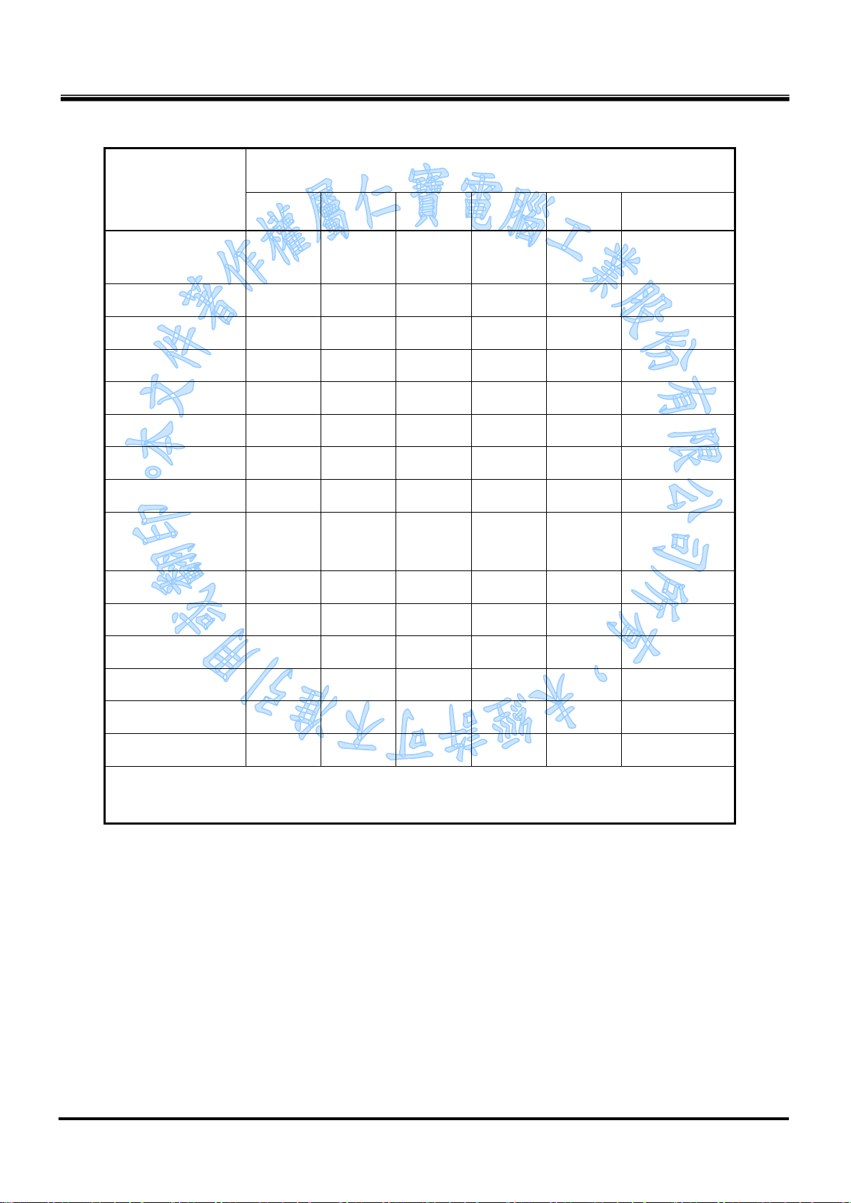
5.1.5
Names and contents of harmful substances in products (TW)
限用物質及其化學符號
單元Unit
印刷電路板組件
(含處理器)
硬碟
光碟機(選配)
記憶體
電腦I/O配件
電源供應器
機殼
螢幕
配件
(含電源線)
鉛
(Pb)
- ○ ○ ○ ○ ○
-
- ○ ○ ○ ○ ○
- ○ ○ ○ ○ ○
- ○ ○ ○ ○ ○
- ○ ○ ○ ○ ○
- ○ ○ ○ ○ ○
- ○ ○ ○ ○ ○
- ○ ○ ○ ○ ○
汞
(Hg)
○ ○ ○ ○ ○
鎘
(Cd)
六價鉻
+6
(Cr
)
多溴聯苯
(PBB)
多溴二苯醚
(PBDE)
散熱模組
喇叭(選配)
相機(選配)
麥克風(選配)
無線裝置(選配)
腳架(選配)
備考1.〝超出0.1 wt %〞及〝超出0.01 wt %〞係指限用物質之百分比含量超出百分比含量基準值。
備考2.〝○〞係指該項限用物質之百分比含量未超出百分比含量基準值。
備考3.〝-〞係指該項限用物質為排除項目。
- ○ ○ ○ ○ ○
- ○ ○ ○ ○ ○
- ○ ○ ○ ○ ○
- ○ ○ ○ ○ ○
- ○ ○ ○ ○ ○
- ○ ○ ○ ○ ○
Tabel 5.5 Taiwan RoHS
Page 20

File: SHC-100 User manual(Eng)_V0.7 (LT
Edit).docx
Date: 2018/07/16
Version: 0.7
Page: 27
(Cr(VI))
(PBB)
(PBDE)
SJ/T 11364
”X”
RoHS
SHC-100
5.1.6
产品中有害物质的名称及含量
部件名称
铅(Pb) 汞(Hg) 镉(Cd)
印刷电路板组件
硬盘
光驱
内存
计算机I/O附件
电源
机箱/附件
电池
本表格依据
○:表示该有害物质在该部件所有均质材料中的含量均在GB/T 26572规定的限值要求以下。
X:表示该有害物质至少在该部件的某一均质材料中的含量超出GB/T 26572规定的限值要求。
注:表中标记
的部件均符合欧盟
X
X
X
X
X
X
X
X
的规定编制
(China)
有害物质
六价铬
○ ○ ○ ○ ○
○ ○ ○ ○ ○
○ ○ ○ ○ ○
○ ○ ○ ○ ○
○ ○ ○ ○ ○
○ ○ ○ ○ ○
○ ○ ○ ○ ○
○ ○ ○ ○ ○
立法。
多溴联苯
多溴二苯醚
Tabel 5.6 China RoHS
 Loading...