

Page 1

User Manual
1
Page 2

1. Specification
2. Pin Definition
3. Software Installation
4. NCC Warning Statement
Outline
5. FCC Warning Statement
Page 3

Bluetooth Module Specification
• Brand: COMPAL
• Model Name: CEX01BT
• Product Name:Bluetooth module
• Supply Voltage: 1.7V~3.6V
• Processor: 32-bit ARM Cortex-M4F
• Memory: 512Kb Flash /64Kb RAM
• Mode: Single Mode BLE v4.2
• GPIOs: Up to 32 GPIOs
• Antenna Designation: Chip Antenna
• Dimension: 6.25mm*12.75mm*1.60mm
• Temperature Range: -20°C~+75°C(Operating)
Page 4
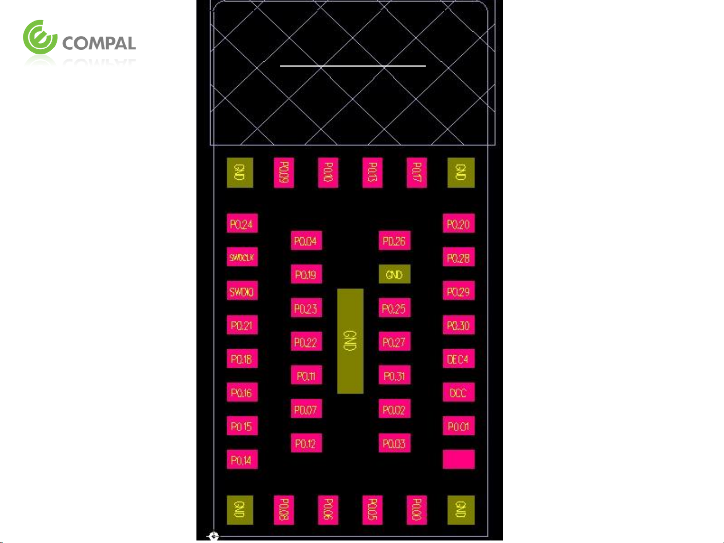
Bottom View
Pin Definition
0.3mm
0.3mm
0.3mm
9
8
7
6
5
4
3
2
10
11
35 36
34
33
32
31
30
29
12 13 14 15
37
38
39
40
43
41
42
16
17
18
19
20
21
22
23
1
28
26 27
25
24
Page 5

Pin No.
Name Pin Function Description
1,10,15,
24,37,43
The pad must be connected to
Serial wire debug clock input
GND Ground
a solid ground plane
2 P0.14 Digital I/O General-purpose digital I/O
3 P0.15 Digital I/O General-purpose digital I/O
4 P0.16 Digital I/O General-purpose digital I/O
5 P0.18 Digital I/O General-purpose digital I/O
6 P0.21 Digital I/O General-purpose digital I/O
7 SWDIO Digital I/O Serial wire debug I/O for
debug and programming
8 SWDCLK Digital input
for debug and programming
9 P0.24 Digital I/O General-purpose digital I/O
11 P0.09 Digital I/O General-purpose digital I/O
12 P0.10 Digital I/O General-purpose digital I/O
13 P0.13 Digital I/O General-purpose digital I/O
14 P0.17 Digital I/O General-purpose digital I/O
16 P0.20 Digital I/O General-purpose digital I/O
17 P0.28 Digital I/O General-purpose digital I/O
18 P0.29 Digital I/O General-purpose digital I/O
19 P0.30 Digital I/O General-purpose digital I/O
20 DEC4 Power 1V3 regulator supply
decoupling.
Input form DC/DC converter
Page 6

Pin No.
21 DCC Power DC/DC converter output pin
22 P0.01 Digital I/O General-purpose digital I/O
23 VCC_NRF Power Power-supply pin
25 P0.00 Digital I/O General-purpose digital I/O
26 P0.05 Digital I/O General-purpose digital I/O
27 P0.06 Digital I/O General-purpose digital I/O
28 P0.08 Digital I/O General-purpose digital I/O
29 P0.12 Digital I/O General-purpose digital I/O
30 P0.07 Digital I/O General-purpose digital I/O
31 P0.11 Digital I/O General-purpose digital I/O
32 P0.22 Digital I/O General-purpose digital I/O
33 P0.23 Digital I/O General-purpose digital I/O
Name Pin Function Description
34 P0.19 Digital I/O General-purpose digital I/O
35 P0.04 Digital I/O General-purpose digital I/O
36 P0.26 Digital I/O General-purpose digital I/O
38 P0.25 Digital I/O General-purpose digital I/O
39 P0.27 Digital I/O General-purpose digital I/O
40 P0.31 Digital I/O General-purpose digital I/O
41 P0.02 Digital I/O General-purpose digital I/O
42 P0.02 Digital I/O General-purpose digital I/O
Page 7

CEX01BT
Software Installation
Step1.
• Programming CEX01BT Module
using NRF52-DK Board and
build as shown in FIG.
• Download and install nRFgo tool
PC
Step2.
NRF52-DK Power
ON
USB cable
Page 8

Step3.
Run the nRFgo tool and program SoftDevice.
Software Installation
3.2
3.3
3.1
3.4
Page 9

Step4.
Program Application
Software Installation
4.1 3.2
4.2
Step5.
CEX01BT programmed to finish and NRF52-DK
Power turn OFF.
4.3
Page 10

NCC Warning Statement
低功率電波輻射性電機管理辦法:
• 第十二條經型式認證合格之低功率射頻電機,非經許可,公司、商號或使用者均不
得擅自變更頻率、加大功率或變更原設計之特性及功能。
• 第十四條低功率射頻電機之使用不得影響飛航安全及干擾合法通信;經發現有干擾
現象時, 應改善至無干擾時方得繼續使用。前項合法通信,指依電信法規定作業之無
線電通信。低功率射頻電機須忍受合法通信或工業、科學及醫療用電波輻射性電機
設備之干擾。
• Article 12
Without permission, any company, firm or user shall not alter the frequency, increase the
power, or change the characteristics and functions of the original design of the certified lower
power frequency electric machinery.
• Article 14
The application of low power frequency electric machineries shall not affect the navigation
safety nor interfere a legal communication, if an interference is found, the service will be
suspended until improvement is made and the interference no longer exists.
Page 11

FCC Warning Statement
This equipment has been tested and found to comply with the limits for a Class B digital device,
pursuant to part 15 of the FCC Rules. These limits are designed to provide reasonable protection
against harmful interference in a residential installation. This equipment generates, uses and can
radiate radio frequency energy and, if not installed and used in accordance with the instructions,
may cause harmful interference to radio communications. However, there is no guarantee that
interference will not occur in a particular installation. If this equipment does cause harmful
interference to radio or television reception, which can be determined by turning the equipment
off and on, the user is encouraged to try to correct the interference by one or more of the
following measures:
- Reorient or relocate the receiving antenna.
- Increase the separation between the equipment and receiver.
- Connect the equipment into an outlet on a circuit different from that to which the receiver is
connected.
- Consult the dealer or an experienced radio/TV technician for help.
You are cautioned that changes or modifications not expressly approved by the party responsible for
compliance could void your authority to operate the equipment.
This device complies with Part 15 of the FCC Rules. Operation is subject to the following two
conditions: (1) this device may not cause harmful interference and (2) this device must accept
any interference received, including interference that may cause undesired operation
Page 12

FCC Warning Statement
This module is intended for OEM integrator. The OEM integrator is still responsible for the FCC
compliance requirement of the end product, which integrates this module.20cm minimum
distance has to be able to be maintained between the antenna and the users for the host this
module is integrated into. Under such configuration, the FCC radiation exposure limits set forth
for an population/uncontrolled environment can be satisfied.
The OEM integrator has to be aware not to provide information to the end user regarding how to
install or remove this RF module in the user manual of the end product. The user manual which
is provided by OEM integrators for end users must include the following information in a
prominent location.
1. To comply with FCC RF exposure compliance requirements, the antenna used for this transmitter
must be installed to provide a separation distance of at least 20 cm from all persons and must
not be co-located or operating in conjunction with any other antenna or transmitter, except in
accordance with FCC multi‐transmitter product procedures.
2. Only those antennas with same type and lesser gain filed under this FCC ID number can be used
with this device.
3. The regulatory label on the final system must include the statement: “Contains FCC ID: GKR-
CEX01BT or using electronic labeling method as documented in KDB 784748.
4. The final system integrator must ensure there is no instruction provided in the user manual or
customer documentation indicating how to install or remove the transmitter module except such
device has implemented two‐ways authentication between module and the host system.
 Loading...