

Page 1

Chapter 5
Disassembly Guide
Page 2

Page 3

HGL30 Service Manual
Contents
Disassembling the Base Unit.......................................................................... 1
Removing the Battery Pack...........................................................................................2
Removing the HDD Module.......................................................................................... 3
Removing the DDR RAM.............................................................................................5
Disassembling the ODD (CD-ROM/DVD-ROM/CD-RW…)......................................6
Removing the Wireless LAN Card................................................................................ 8
Removing the Keyboard.............................................................................................. 10
Removing the Switch Board........................................................................................12
Removing the Bluetooth Module ................................................................................ 13
Removing the LCD Module........................................................................................ 14
Removing the NB Thermal Module, Fan, and CPU.................................................... 17
Removing the Logic Upper ......................................................................................... 20
Removing the Touch Pad Board.................................................................................. 22
Removing the Finger Printer Board............................................................................. 24
Removing the Speakers............................................................................................... 25
Removing the Motherboard.........................................................................................26
Removing the Modem Card ........................................................................................ 28
Removing the VGA Board and the VGA Thermal Module.........................................29
Removing the CRT Board and IO Board..................................................................... 30
Disassembling the Display and the Inverter Board..................................................... 32
Disassembling the CMOS ........................................................................................... 35
i
Page 4

Page 5

HGL30 Service Manual
Disassembling the Base Unit
These are the directions for disassembling the base unit. You will need a 5.5mm Nut
Driver, a medium size Philips screwdriver.
These directions are to disassemble the complete unit and are cross-referenced to Section
7 for the replacement of component parts.
Before disassembly, make sure the notebook is powered off.
5-1
Page 6
HGL30 Service Manual
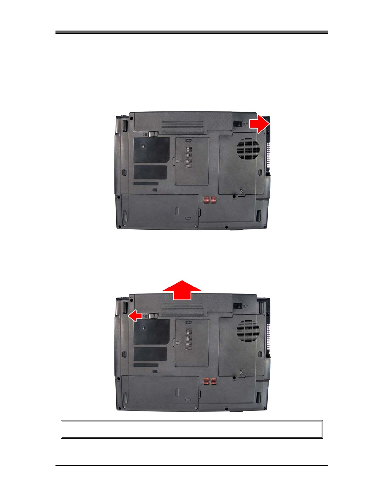
Removing the Battery Pack
To remove the battery pack from the battery bay, follow the steps below:
1. Turn the notebook upside down.
2. Unlock the battery lock. (Move the lock to the right.)
3. Slide the latch lock in the direction of the arrow. The battery pack will pop-up
automatically.
4. Gently pull the battery pack out of its housing.
NOTE: Always start laptop disassembly by removing the battery pack first.
5-2
Page 7
HGL30 Service Manual
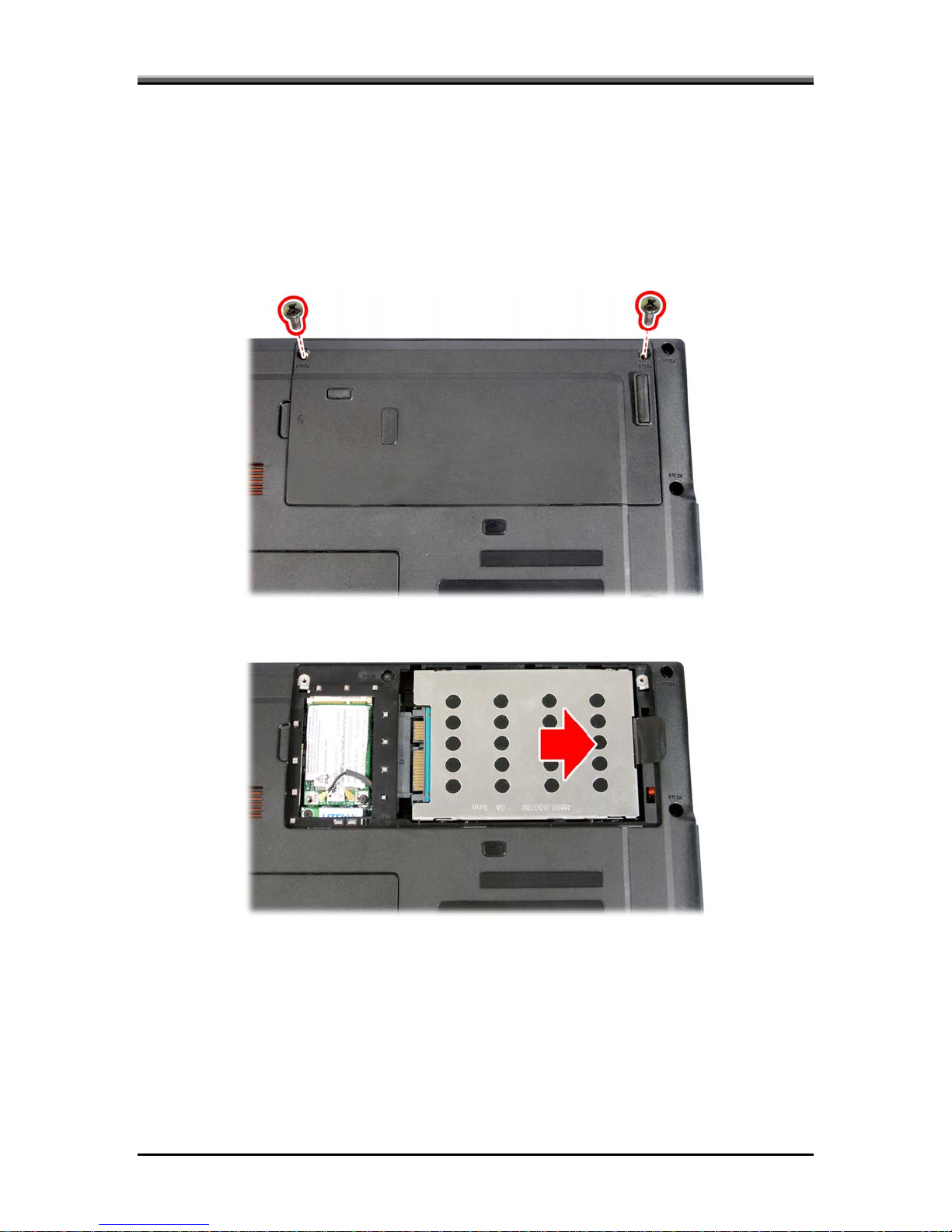
Removing the HDD Module
Follow the steps below to remove the HDD module:
1. Turn the notebook upside down.
2. Remove the two screws securing the HDD cover, and then remove the cover.
3. Pull out the Mylar tab to remove the HDD unit.
5-3
Page 8
HGL30 Service Manual
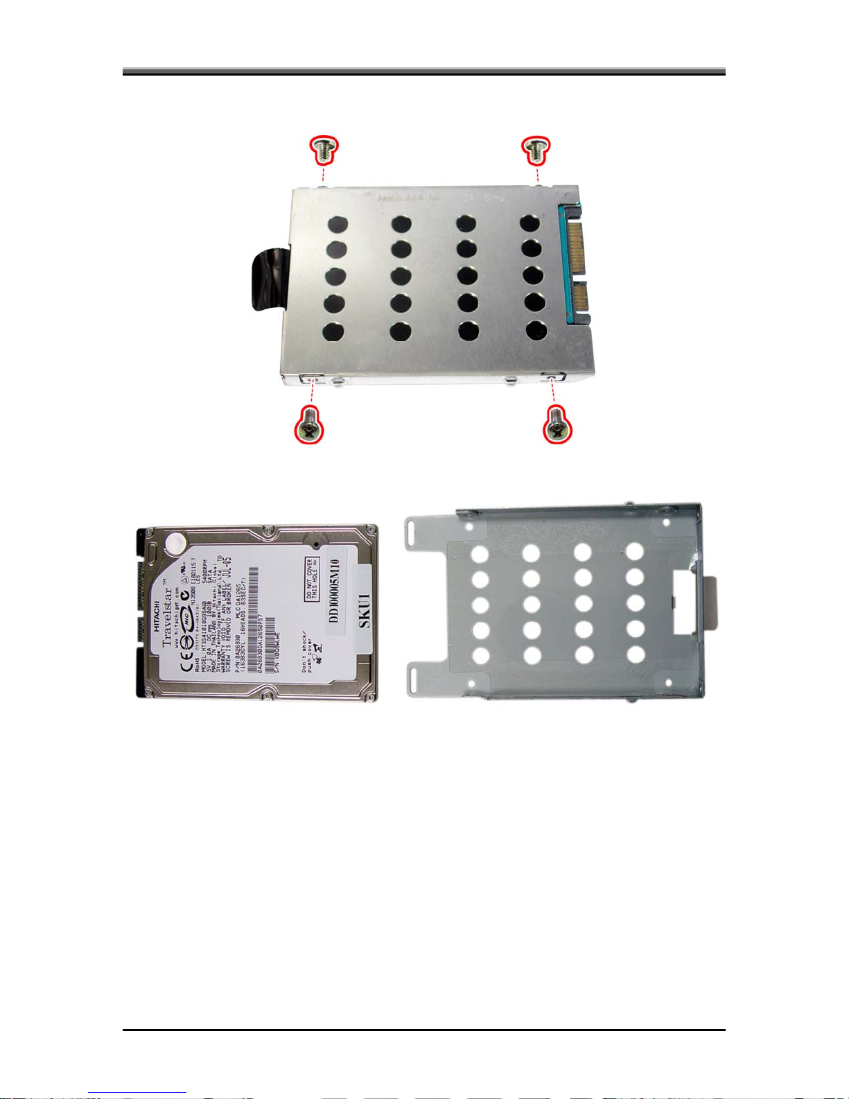
4. Remove the four screws to take off the HDD case.
5. Remove the HDD module from the HDD case.
5-4
Page 9
HGL30 Service Manual
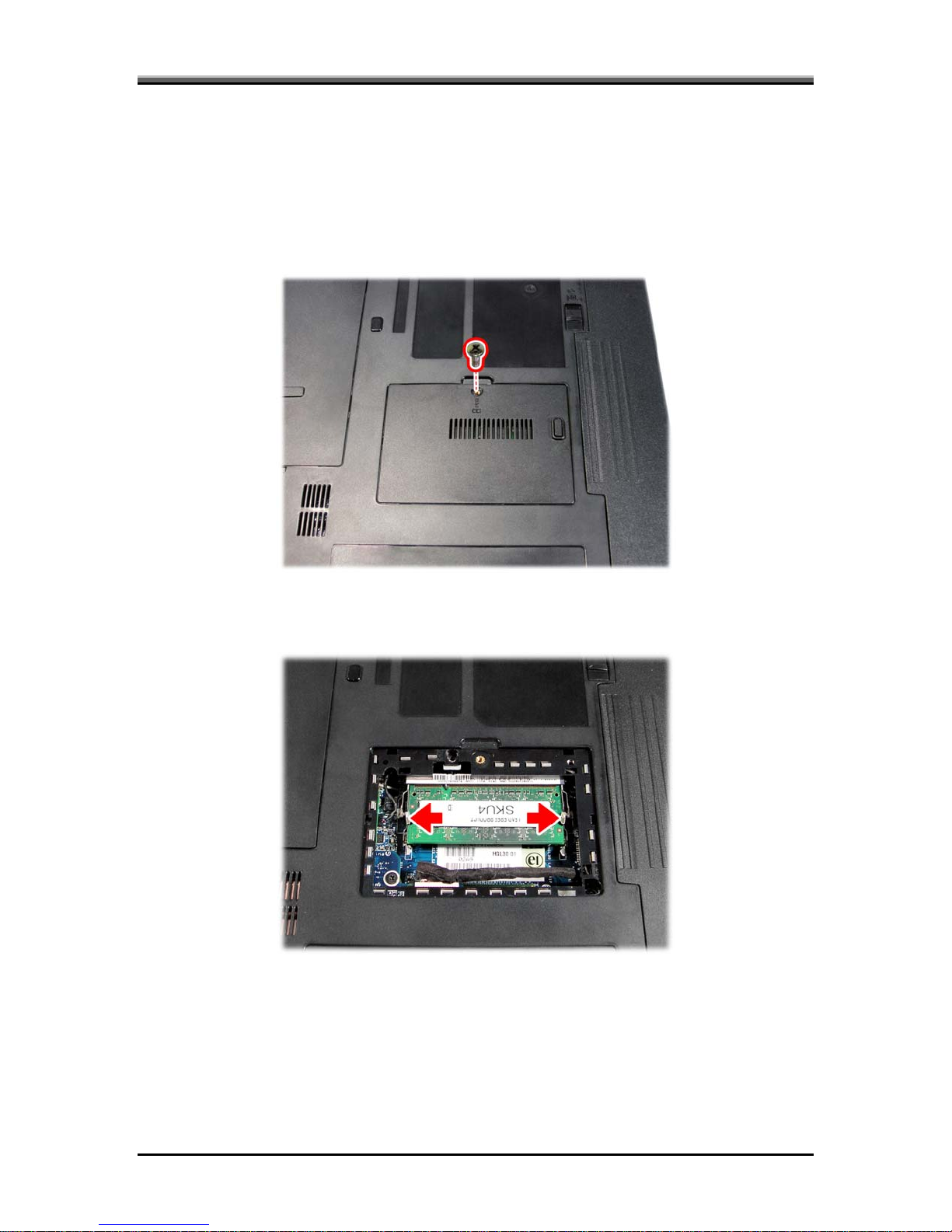
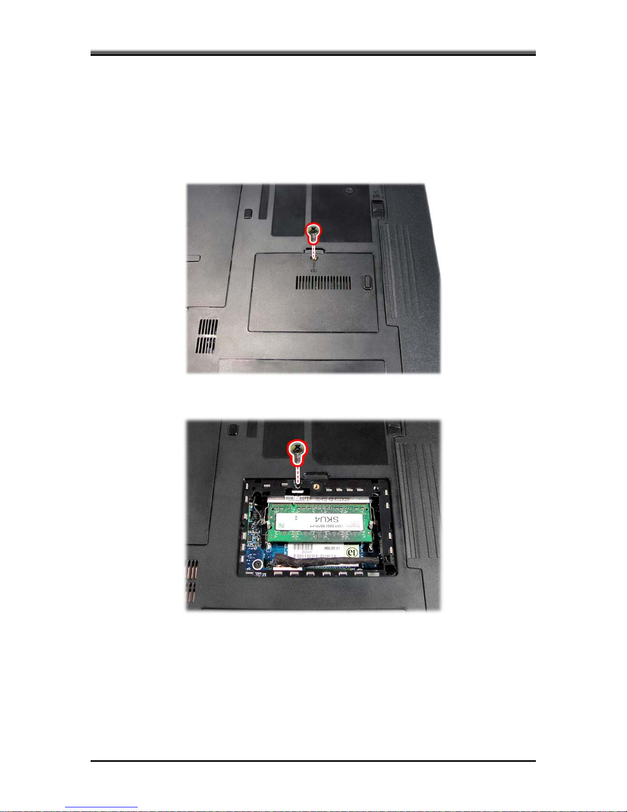
Removing the DDR RAM
Follow the steps below to remove the DDR RAM:
1. Turn the notebook upside down.
2. Remove the screw securing the RAM cover, and then remove the cover.
3. Push the latches to release the RAM module. A spring will force one end of the
module up.
4. Grasp the module and pull it out.
5-5
Page 10
HGL30 Service Manual
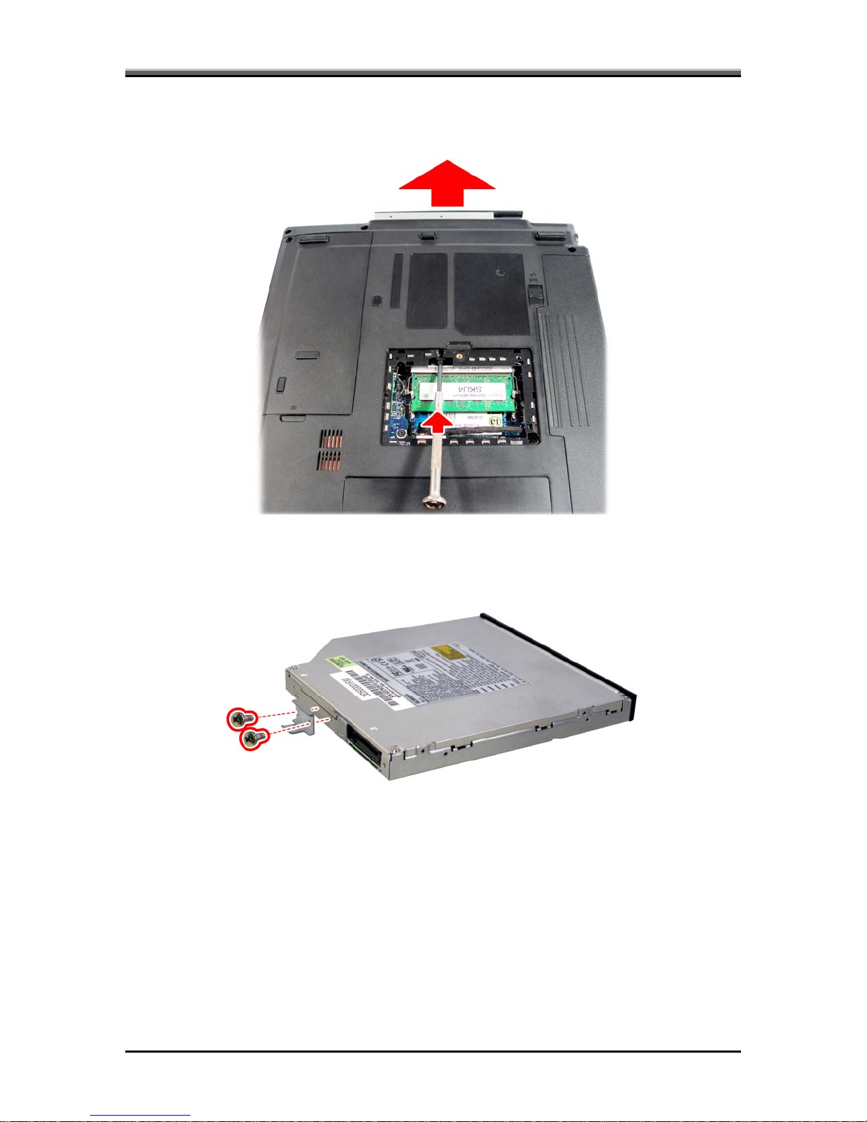
Disassembling the ODD (CD-ROM/DVD-ROM/CD-RW…)
Follow the steps below to disassemble the optical drive:
1. Turn the notebook upside down.
2. Remove the screw securing the RAM cover, and then remove the cover.
3. Remove the screw securing the optical drive.
5-6
Page 11
HGL30 Service Manual
4. Use a thin tool such as a flat screwdriver to slide out the optical drive in the direction
of the arrow.
5. Gently pull out the optical drive.
6. Remove the two screws from the bracket plate, and then remove the bracket plate.
5-7
Page 12
HGL30 Service Manual
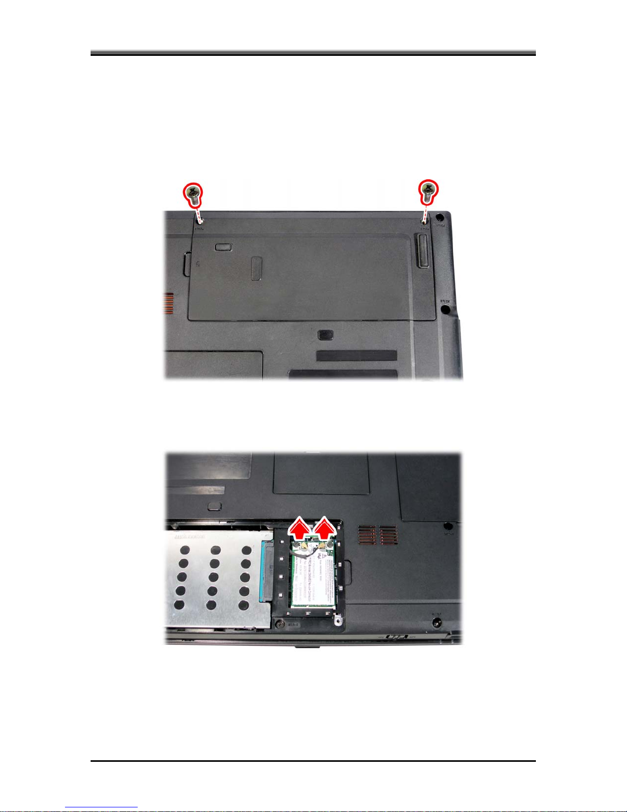
Removing the Wireless LAN Card
Follow the steps below to remove the wireless LAN card:
Turn the notebook upside down.
1. Remove the two screws securing the HDD cover, and then remove the cover.
2. Detach the two ends of the wireless LAN antenna (black and white).
5-8
Page 13

HGL30 Service Manual
3. Remove the two screws securing the wireless LAN card. The LAN card will pop up.
4. Grasp the wireless LAN card and pull it out.
CAUTION: Do not touch the connectors on the wireless LAN card or on the
computer. Debris on the connectors may cause malfunction.
5-9
Page 14

HGL30 Service Manual
Removing the Keyboard
Open the display panel and follow the steps below to remove the keyboard.
1. Insert a thin tool such as a flat screwdriver into the gap between the strip cover and
keyboard to lever the strip cover up. Then remove the strip cover.
2. Remove the three screws securing the keyboard.
5-10
Page 15

3. Turn over the keyboard, revealing the keyboard cable underneath.
HGL30 Service Manual
4. Use a thin tool such as a screwdriver to lever up the connector bracket and disconnect
the keyboard cable from the motherboard.
5. Lift and remove the keyboard.
5-11
Page 16

HGL30 Service Manual
Removing the Switch Board
Open the display panel and follow the steps below to remove switch board.
1. Remove the three screws securing the switch board to the logic upper .
2. Disconnect the switch board cable, and remove the switch board.
5-12
Page 17

HGL30 Service Manual
Removing the Bluetooth Module
To remove the Bluetooth module, first remove keyboard strip cover. Then follow the
steps below:
1. Disconnect the Bluetooth cable.
2. Remove the screw securing the Bluetooth module to the logic upper.
3. Remove the Bluetooth module.
5-13
Page 18

HGL30 Service Manual
Removing the LCD Module
To remove the LCD module, first remove the keyboard. Detach the two ends of the
wireless LAN antenna (black and white) as described earlier. Then follow the steps
below:
1. Release the two screws securing the LCD module from the rear side, and one screw
from the bottom side.
2. Remove the RAM cover.
5-14
Page 19

HGL30 Service Manual
3. Disconnect the LCD cable connector.
4. Turn the notebook over. The keyboard should have been disassembled. If not, remove
it now.
5. Disconnect the black LCD power (LVDS) cable, CMOS cable, and microphone cable
from the motherboard. Pull out the wireless LAN antenna wires from the logic upper.
5-15
Page 20

HGL30 Service Manual
6. Remove the four screws securing the LCD module to the logic upper.
7. Remove the LCD module.
5-16
Page 21

HGL30 Service Manual
Removing the NB Thermal Module, Fan, and CPU
Follow the steps below to remove the NB thermal module, Fan, and CPU:
1. Turn the notebook upside down.
2. Remove the screw securing the thermal cover, and then remove the cover.
3. Disconnect the Fan connector and DC-in connector from the motherboard as shown.
5-17
Page 22

HGL30 Service Manual
4. Remove the three screws securing the Fan from the motherboard to remove the Fan
module.
5. Remove the four screws securing the NB thermal module to the motherboard
following the numbered sequence in reverse.
NOTE: When reassembling the NB thermal module, reinstall the module in place
and secure the screws, following the numbered sequence above.
5-18
Page 23

HGL30 Service Manual
6. Lift and remove the NB thermal module from the motherboard.
7. Turn the cam on the CPU socket with a flat-blade screwdriver so that the notch on the
cam is aligned with the open side of the CPU socket to unlock the CPU.
8. Gently lift out the CPU.
CAUTION: When you remove the NB thermal module, use the CPU grease tool to
remove the grease on the CPU and NB thermal module. Reapply fresh grease before
reinstalling the NB thermal module.
5-19
Page 24

HGL30 Service Manual
Removing the Logic Upper
To remove the logic upper, first remove the battery pack, HDD, memory module, ODD,
wireless LAN card, NB thermal module, Fan, keyboard, switch board, Bluetooth, and
LCD module as described in the preceding sections. Follow the steps below to remove
the logic upper.
1. Turn the computer upside down and remove the following nine screws from the
bottom side of the notebook.
2. Turn the computer over again and remove the five screws securing the logic upper.
5-20
Page 25

HGL30 Service Manual
3. Detach the Bluetooth cable, speaker cable, touch pad cable, and finger printer cable as
shown.
4. Lift off the logic upper.
5-21
Page 26

HGL30 Service Manual
Removing the Touch Pad Board
To remove the touch pad board, first remove the keyboard, LCD module, and logic upper.
Then follow the steps below:
1. Detach the touch pad cable. Remove the screw securing the touch pad bracket to the
rear side of the logic upper.
2. Slide the bracket forward slightly and remove it.
5-22
Page 27

3. Remove the touch pad board by lifting it gently.
HGL30 Service Manual
5-23
Page 28

HGL30 Service Manual
Removing the Finger Printer Board
To remove the finger printer board, first remove the keyboard, LCD module, and logic
upper. Then follow the steps below:
1. Remove the screw securing the finger printer bracket to the rear side of the logic
upper.
2. Remove the bracket and the finger printer board.
5-24
Page 29

HGL30 Service Manual
Removing the Speakers
To remove the speakers, first remove the keyboard, LCD module, and logic upper. Then
follow the steps below:
1. Remove the two screws securing the left and right speakers to the rear side of the
logic upper.
2. Remove the speakers.
5-25
Page 30

HGL30 Service Manual
Removing the Motherboard
To remove the motherboard, first remove the keyboard, LCD module, and logic upper.
Then follow the steps below:
1. Remove the screw securing the motherboard to the base. Disconnect the IO cable
from the motherboard.
2. Disconnect the CRT and modem cable connectors from the front side of the
motherboard.
5-26
Page 31

HGL30 Service Manual
3. Remove the motherboard after making sure that all connectors are removed from their
respective sockets.
5-27
Page 32

HGL30 Service Manual
Removing the Modem Card
The modem card is securing to the front side of the motherboard. Remove the
motherboard before you start. Then follow the steps below:
1. Remove the two screws securing the modem board to the motherboard.
2. Remove the modem card.
5-28
Page 33

HGL30 Service Manual
Removing the VGA Board and the VGA Thermal Module
To remove the VGA board and the VGA thermal module, remove the motherboard first.
Then follow the steps below:
1. Release the four screws securing the VGA board to the motherboard, and remove the
VGA board.
2. Remove the four screws securing the VGA thermal module to the VGA board
following the numbered sequence in reverse.
NOTE: When reassembling the VGA thermal module, reinstall the module in place
and secure the screws following the numbered sequence above.
5-29
Page 34

HGL30 Service Manual
Removing the CRT Board and IO Board
To remove the CRT board and IO board, first remove the keyboard, LCD module, and
logic upper. Follow the steps below to remove these two boards.
1. Remove the screw securing the CRT board to the base, and the two hexagonal VGA
screws from the side of the CRT board.
5-30
Page 35

2. Detach the cables from the CRT board and IO board.
HGL30 Service Manual
3. Remove the CRT board (A) and IO board (B).
5-31
Page 36

HGL30 Service Manual
Disassembling the Display and the Inverter Board
To disassemble the display and inverter board, first remove the keyboard and LCD
module. Then follow these steps:
1. Remove the four screw pads and four screws securing the LCD bezel to the LCD
module.
2. Carefully insert your fingers between the display and the LCD bezel, and gently pry
up the LCD bezel.
5-32
Page 37

HGL30 Service Manual
3. Remove the three screws mounting the display and inverter board to the LCD
module.
y Two screws on the display.
y One screw on the inverter board.
4. Disconnect the two connectors on either side of the inverter board.
5. Remove the inverter board.
5-33
Page 38

HGL30 Service Manual
6. Gently lift out the display. Remove the eight screws securing the hinges to the
display.
7. Detach the LVDS cable from the back of the LCD panel.
5-34
Page 39

HGL30 Service Manual
Disassembling the CMOS
To disassemble the CMOS, first remove the keyboard, LCD module, and LCD bezel.
Then follow the steps below:
1. Release the two screws securing the CMOS bracket to the chassis.
2. Remove the CMOS bracket.
3. Disconnect the CMOS connector and remove the CMOS board.
5-35
 Loading...