

Page 1
coffee grinders
instructions manual
PROFESSIONAL ESPRESSO
K3
K3 ELITE
K6
K6 SILENZIO
K6 PB
K8 SILENZIO
K10 CONIC
K10 CONIC PB
K10 MASTER CONIC
K10 MASTER CONIC PB
Page 2

index
1. SAFETY MEASURES 1
2. DESCRIPTION 2
3. INSTRUCTIONS 3
4. IDENTIFICATION 3
5. TECHNICAL CARACTERISTICS 4
6. EXTERNAL COMPONENTS 6
7. INSTALLATION 8
8. OPERATION 10
9. CONFIGURATION 13
10. CLEANING 15
11. MAINTENANCE 16
12. EC CONFORMITY 22
Page 3

1. SAFETY MEASURES
NOTE: The manufacturer will not be held responsible for any damages resulting from
improper use of the equipment, or for not following the safety measures as outlined
below.
Safety measures incorporated into our grinders:
• Special screw to maintain the hopper xed in place.
• Access restrictor in the grind group.
Owners: Please pay careful attention with the following instructions:
• The grinder should be used exclusively for the function for which it was
designed: grinding whole bean coffee.
• Do not use this grinder to grind other types of food products such as dry fruit,
sugar or spices.
• Children should be supervised to ensure that they do not play with the
appliance.
• This appliance is not intended for use by persons (including children) with
reduced physical, sensory or mental capabilities, or lack of experience and
knowledge, unless they have been given supervision or instruction concerning
use of the appliance by a person responsible for their safety.
• Any other use of the machine will be considered improper and dangerous.
• Do not put liquids in contact with internal or external parts of this grinder while
ON or OFF, with the exception of parts expressly outlined in the “CLEANING”
section of this manual. If liquids do come in contact with the grinder,
immediately disconnect electrical connection and carefully clean the affected
areas. If it is necessary to access the interior parts of the grinder, contact your
local service professional.
• In case of any damage to parts or components, we recommend contacting your
local service professional to help with repair or replacement of such parts,
thereby guaranteeing the maintenance of the security standards of the grinder.
• If the supply cord is damaged, it must be repalced by the manufacturer, its
service agent or similarly qualied persons in order to avoid a hazard.
• Only an authorized distributor should replace the main power cable of the
grinder.
An equipotential grounding lug is provided with this unit. Some countries
require the grounding lug be properly attached to the rear of the frame by the
authorized installer. The installation location is marked by the equipotential
bonding symbol (5021 of IEC 60417-1) on the unit´s frame. (Only for MASTER
models).
K01068 | v. 02/09/2016 | Ref. quality process 002/03 | ORIGINAL INSTRUCTIONS
1
Page 4

SOUND DECIBEL LEVEL
The level of sound emitted in different models is:
Sound decibel level With coffee
K3, K3 ELITE 75,3 dB
K6, K6 PB 73,2 dB
K6 SILENZIO 68,7 dB
K8 SILENZIO 70,2 dB
K10 CONIC, K10 CONIC PB 68,4 dB
K10 MASTER CONIC, K10 MASTER CONIC PB 67,8 dB
2. DESCRIPTION
Your new grinder has been designed using the most sophisticated technologies in
existence. The result is a product of high quality that offers the assurance of the best
results possible. Our products are manufactured by hand, one by one, following the
strictest quality requirements. In the manufacturing process, we use only the highest
quality materials (aluminum, stainless steel, etc.) especially designated for being in
contact with food stuff.
For the optimum functionality of the grinder models described in this user manual,
the maximum work cycles are as follows:
Model
K3, K3 ELITE 2 minutes 10 minutes
K6, K6 SILENZIO, K6 PB 5 minutes 10 minutes
K8 SILENZIO, K10 CONIC, K10 CONIC PB 2 minutes 10 minutes
K10 MASTER CONIC, K10 MASTER CONIC PB 2 minutes 10 minutes
2
ORIGINAL INSTRUCTIONS | Ref. quality process 002/03 | v. 02/09/2016 | K01068
Working cycle
ON OFF
Page 5
3. INSTRUCTIONS
3.1. This manual is designed to provide the necessary information to correctly
install, use and maintain the grinder, as well as to highlight precautions for users to
keep in mind. To ensure the best operation of the coffee grinder, please follow the
instructions as outlined in this manual. This manual should be saved for the life of the
grinder, and should always be at the disposal of the operator.
3.2. This manual contains special terminology such as:
• Words in BOLD indicate important points or terminology.
• Numbers in parenthese after a word, indicate the location of this item in a parts
diagram.
Example: ( ) - Hopper lid
• Icons:
Information Atention Equipotential symbol
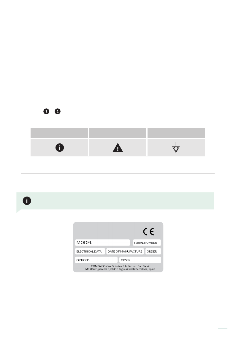
4. IDENTIFICATION
In the grinder information plaque is the following manufacturing/product information.
NOTE: The manufacturer reserves the right to change components/congurations of
any model, according to the different geographic market demands.
K01068 | v. 02/09/2016 | Ref. quality process 002/03 | ORIGINAL INSTRUCTIONS
3
Page 6

5. TECHNICAL CARACTERISITICS
5.1. Usage
The coffee grinders are intended for use on commercial premises and facilities where
ground coffee is required, or in small stores that sell coffee. The grinder must only be
used to grind coffee beans. Any use other than this will be considered improper and
dangerous.
NOTE: The manufacturer will not be held responsible for any damages resulting from
improper use of the equipment, or for not following the safety measures as outlined
below.
5.2. Technical data
100 V
100 V
110 V
220 V
230 V
240 V
400 V ψ
Model
50 Hz
60 Hz
60 Hz
60 Hz
50 Hz
50 Hz
50Hz
208 V ψ
60 Hz
K3,
K3 ELITE
K6,
K6 SILENZIO,
K6 PB
K8
SILENZIO
K10 CONIC,
K10 CONIC
PB
K10 MASTER
CONIC,
K10 MASTER
CONIC PB
4
Electric
power
Spin
speed
Electric
power
Spin
speed
Electric
power
Spin
speed
Electric
power
Spin
speed
Electric
power
Spin
speed
ORIGINAL INSTRUCTIONS | Ref. quality process 002/03 | v. 02/09/2016 | K01068
200 200 230 210 210 225
1,320 1,620 1,650 1,640 1,340 1,345 rpm
230 230 250 265 240 240 (W)
1,320 1,600 1,650 1,700 1,395 1,400 rpm
600 700 700 730 610 630 (W)
1,270 1,530 1,580 1,500 1,290 1,310 rpm
890 960 825 825 800 850 780 840 (W)
335 388 400 375 325 331 350 390 rpm
850 1,000 935 930 950 975 780 840 (W)
326 378 325 388 340 345 350 390 rpm
(W)
Page 7

Model
Ø Burrs
Production*
50Hz
Production*
60Hz
Hopper
capacity
Mini-hopper
capacity
(optional)
Doser
capacity
Doser lever
position
Net weight
K3,
K3 ELITE
2.3
58
8.2
3,7
9.5
4,3
1.76
38.5
0.6
275
0.66
300
right
left
15.07
6,85
K6,
K6 SILENZIO,
K6 PB
2.5
64
13
6
15
7
3.74
1700
0.6
275
0.66
300
right
left
25.47
11,58
K8 SILENZIO
3.3
83
33
15
38.5
17,5
3.74
1700
0.6
275
0.66
300
right
left
28.6
13
K10 CONIC,
K10 CONIC
PB
2.65
Conic 68
33
15
38.5
17,5
3.74
1700
0.6
275
0.66
300
right
left
37.24
16,93
K10 MASTER
CONIC,
K10 MASTER
CONIC PB
2.65
Conic 68
37
17
44
20
3.74
1700
0.6
275
0.66
300
right
left
37.24
16,93
in
mm
lb/h
Kg/h
lb/h
Kg/h
lb
gr
lb
gr
lb
gr
lb
Kg
19.5
495
25
635
25
Height
Width
Depth
6.7
14.37
170
365
8.46
15.74
215
400
8.46
15.74
635
215
400
in mm in mm in mm in mm in mm
Mini-hopper
Height
Widht
Depth
16.5
6.7
14.37
420
170
365
22
8.46
15.74
560
215
400
22
8.46
15.74
560
215
400
in mm in mm in mm in mm in mm
* Production is based on a medium-roasted coffee and an Espresso grind.
K01068 | v. 02/09/2016 | Ref. quality process 002/03 | ORIGINAL INSTRUCTIONS
25
8.46
15.74
22
8.46
15.74
635
215
400
560
215
400
26.77
8.46
15.74
23.82
8.46
15.74
680
215
400
605
215
400
5
Page 8
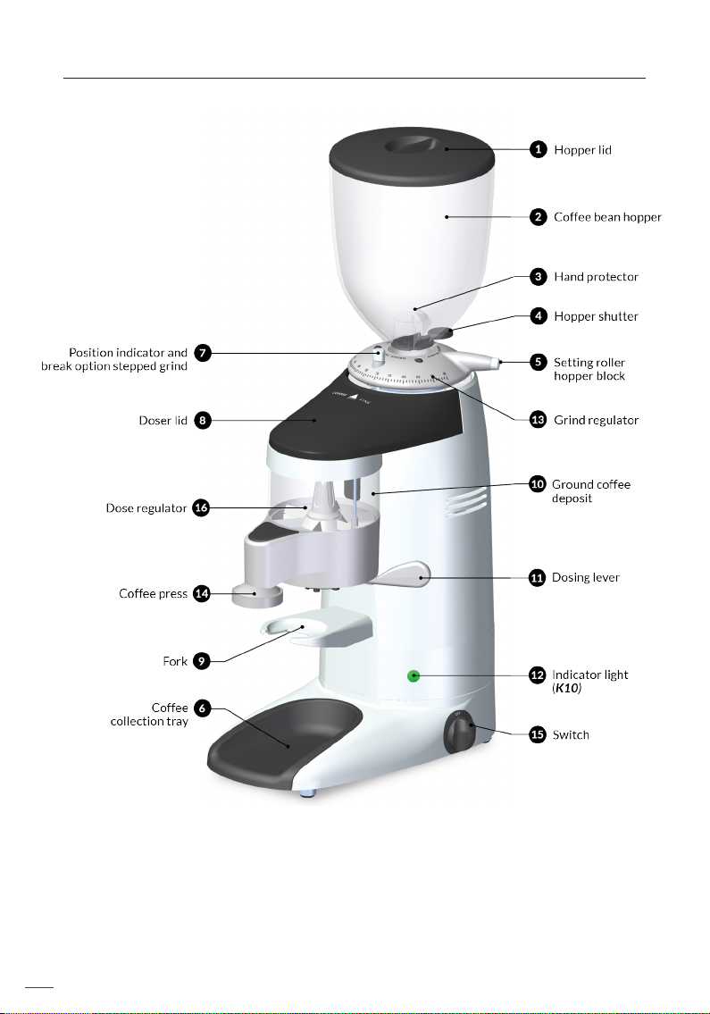
6. EXTERNAL COMPONENTS
K10 MASTER CONIC
6
ORIGINAL INSTRUCTIONS | Ref. quality process 002/03 | v. 02/09/2016 | K01068
Page 9

K3 ELITE
K01068 | v. 02/09/2016 | Ref. quality process 002/03 | ORIGINAL INSTRUCTIONS
7
Page 10

7. INSTALLATION
7.1. General Warnings
The person installing the grinder should carefully read this instruction manual
before installation. The installation of this machine should be completed by
qualied and authorized personnel, and all norms of safety and sanitation should be
followed.
7.2. Important Warnings
The operator of the grinder should be a responsible adult, and a never a minor
or person incapable of safely using such equipment. When using the grinder,
the following precautions should be followed:
• No bare feet.
• No wet hands or feet.
• Do not submerge in water.
• Do not expose the grinder to sun or other atmospheric conditions.
• Do not place any type of object in the coffee entrance or exit while the grinder
is running. (It should be kept in mind that the cutting burrs continue turning for
a couple revolutions after the grinder is powered off).
• To disconnect the grinder, use the main power switch and never the power
cable, to avoid a possible short circuit.
This unit is provided with an equipotential grounding lug that is to be properly
attached to the rear of the frame by the authorized installer. The installation
location is marked by the equipotential bonding symbol (5021 of IEC 60417-1)
on the unit´s frame. (Only for MASTER models).
8
ORIGINAL INSTRUCTIONS | Ref. quality process 002/03 | v. 02/09/2016 | K01068
Page 11

7.3. Where to use
The grinder should be installed on a at, stable surface. The minimum
dimensions of the work space should be as follows:
Model Height Width Depth
K3, K3 ELITE 20.27 515 7.28
K3, K3 ELITE
Mini-hopper (optional)
K6, K6 SILENZIO, K6 PB 25.78 655 9.25 235 16.53 420
K8 SILENZIO 25 655 9.25 235 16.53 420
K10 CONIC, K10 CONIC PB 25 655 9.25 235 16.53 420
K10 MASTER CONIC,
K10 MASTER CONIC PB
17.32 440 7.28
27.55 700 9.25 235 16.53 420
in mm in mm in mm
185
185
15.15 385
15.15 385
7.4. Grinder Installation
Before grinder installation, the following should be considered:
• The grinder information plaque data coincides with the electrical system on
site.
• The electrical outlet coincides with the grinder plug.
• The electric power at the location of installation should meet the minimum
required to properly run the grinder.
• The installation site should have the proper electrical overload protections.
• The grinder should be properly grounded as specied by local code.
NOTE: The grinder should be used in environments with mínimum temperature
of 77-86F and should not be installed in places (such as industrial kitchens) where
cleaning is done with direct water spray cleaning.
K01068 | v. 02/09/2016 | Ref. quality process 002/03 | ORIGINAL INSTRUCTIONS
9
Page 12

8. REGULATION
8.1. Grinder set up
Place the hopper ( ) on the grind regulator ( ) and make sure the bean trap ( )
is in the closed position. Lock the hopper ( ) in place using a at head screw driver
to gently tighten the hopper security screw making it match to the hole at the bean
hopper collar ( ) (Fig. 1).
Remove the hopper lid ( ), ll the hopper with coffee ( ), and replace the lid on the
hopper ( ) (Fig. 2).
Plug in the grinder, and place the main power switch ( ) ON-OFF to position ON and
open the bean trap ( ) to allow coffee to pass into the grind chamber.
10
ORIGINAL INSTRUCTIONS | Ref. quality process 002/03 | v. 02/09/2016 | K01068
Page 13

8.2. Grind adjustment system
8.2.1. Micrometrical system / Parallel micrometrical system
Rotate the grind regulator ( ) until reaching the grind level desired. Rotating the
grind regulator counterclockwise will result in a courser grind; turning the regulator
clockwise will result in a ner grinder* (Fig. 3).
Once you reach the desired grinding point, you can x the grinding regulation ( )
using the regulation break ( ) (Fig. 4). Except K3 and K3 ELITE models.
*NOTE: Changing grind settings must be done when the grinder is on and burrs are in motion.
Not doing this suposes that the burrs will gunk up and cleaning will be required.
8.2.2. Stepped grind adjustment
In the stepped adjustment versions, the positions on the grind regulator are limited
by “steps” that are dened by the hole and pin points (Fig. 5).
The instructions detailed in section 8.2.1. on adjusting the regulator should be
followed, while at the same time, pulling the brake post ( ) (Fig. 5) up to release the
locking action of the post.
K01068 | v. 02/09/2016 | Ref. quality process 002/03 | ORIGINAL INSTRUCTIONS
11
Page 14

NOTE: If the output is very slow, it could mean that the coffee is being ground too
ne. If the output is very fast, it could mean that the coffee is being ground too
coarse. A perfect espresso grind is found when the grind point gives an infusion of
25 ml of coffee in 25 seconds using 7 grams of ground coffee.
8.3. Regulating the coffee serving
The dispensers are factory adjusted to serve an amount of approximately 7 gr of
ground coffee, but this quantity can be regulated between 6 and 10 gr, as follows:
1. Remove the ground coffee dispenser lid ( ) and turn the dispensing regulation
screw ( ) clockwise to obtain a smaller amount of coffee, and counterclockwise
to obtain a larger amount (Fig. 6).
2. Once the quantity of eachserving has been regulated, replace the ground coffee
dispenser lid ( ).
12
ORIGINAL INSTRUCTIONS | Ref. quality process 002/03 | v. 02/09/2016 | K01068
Page 15

9. OPERATION
9.1. Main switch
The main swith ( ) has 2 positions of use, ON–OFF
ON: Working
OFF: Not working
9.2. Use
To turn the machine on and off use the ON–OFF switch ( ). The machine will start
to grind the coffee. If the automatic stop option is incorporated, the grinder will stop
grinding when the dispenser reaches the maximum level, and will restart after 8
portions of coffee have been served, grinding again to the maximum level.
If the machine does not incorporate the automatic stop option, we recommend that
you ll the doser 75% of its capacity in order to guarantee consistent dosing.
To serve the coffee servings, place the portalter on the fork ( ) as far in as possible
so that it is positioned under the ground coffee discharge tube. Pull the dispensing
lever ( ) to obtain one coffee serving (one serving is equal to one cup of coffee), and
release it so it returns to its normal position (Fig. 7).
K01068 | v. 02/09/2016 | Ref. quality process 002/03 | ORIGINAL INSTRUCTIONS
13
Page 16

9.3. Static press
Take the portalter and place it under the coffee tamper ( ), pressing upwards to
pack the coffee (Fig. 7).
9.4. Telescopic press
When using the telescopic coffee press option, place the portalter
on the fork ( ) and push the coffee tamper downwards (Fig. 8).
14
ORIGINAL INSTRUCTIONS | Ref. quality process 002/03 | v. 02/09/2016 | K01068
Page 17

10. CLEANING
10.1. General cleaning
To ensure that the grinder functions properly, and produces the highest quality grind
possible, the parts that come into contact with coffee should cleaned periodically.
General Cleaning guidelines as follows:
• Always turn the main power switch to the OFF position ( ).
• Unplug the machine from the power source.
• Do not submerge the grinder in water or use power washing devises.
• The appliance is not to be cleaned with a water jet.
10.2. Bean hopper cleaning
In order to properly clean the bean hopper ( ), rst empty out all remaining beans
and fragments.
To remove the hopper, rst close the bean trap ( ), and then loosen the hopper lock
screw ( ) and lift the hopper straight up.
Clean the hopper ( ) with a moist soft cloth or with a small amount of water and
soap to eliminate any oily residue from the beans.
Replace the bean hopper ( ) following the same steps as the removal process, but
in reverse.
10.3. Ground coffee deposit cleaning
To clean the ground coffee holder, rst empty all the coffee inside it. Remove the
ground coffee dispenser lid ( ) and clean the inside, using a small brush.
10.4. Grind chamber cleaning
It is recommended that the grind chamber be cleaned monthly with a cleaner as
recommended by Compak. This process will eliminate smelly residues from the
coffee remains, which can negatively affect the quality of the brewed coffee.
K01068 | v. 02/09/2016 | Ref. quality process 002/03 | ORIGINAL INSTRUCTIONS
15
Page 18

The steps to follow are:
• In order to properly clean the bean hopper , rst empty out all remaining beans
and fragments.
• Close the bean trap on the hopper ( ) and grind out the remaining coffee in the
grind chamber.
• Remove any remaining coffee beans from the bean hopper ( ).
• Pour the recommended grinder cleaning product into the bean hopper ( ) and
open the bean trap ( ), allowing the cleaning product to pass into the grind
chamber.
• Grind the cleaning product at a medium course grind setting until the recommended
amount is passed through the system and nothing remains in the grind chamber.
• Clean the hopper ( ) and rell with coffee beans.
• Discard the rst 2-3 doses of coffee to assure that the residual cleaning product
is removed from the grind chamber and set the grind regulator to the desired
setting ( ).
Following these steps will ensure that the grinder is clean and ready for use.
We do not recommend the taking apart of the grind assembly unless changing burrs,
or removing a blockage/obstruction in the grind chamber. Removal of the grind
assembly should be performed by a qualied service technician.
10.5. Cleaning the outside of the grinder
To clean the exterior of the grinder, rst wipe with a dry soft cloth, and then gently
wipe with a damp soapy cloth.
11. MAINTENANCE
11.1. General warning
Before performing any type of maintenance you should:
• Always turn OFF the main power switch to the OFF position ( ).
• If the grinder is jammed, unplug it from the power source and contact an
authorized service technician.
Not following these warnings can compromise the safety of the grinder as well as
the user.
16
ORIGINAL INSTRUCTIONS | Ref. quality process 002/03 | v. 02/09/2016 | K01068
Page 19

11.2. General maintenance of the grind chamber
To guarantee the efciency and correct operation of the grinder, it is essential to
follow manufacturer instructions and ensure that all maintenance work is carried
out by qualied staff.
Dull burrs will result in; a lower quality grind, greater heat generation in the coffee
and grinder, increased electrical consumption, and nally it puts additional stress on
the grinder motor.
NOTE: Based on extensive experience and a medium-hard coffee blend, we
recommend replacing the burrs after grinding 350 Kg/770 lb of coffee.
Steel Red Speed Lucidate
K3, K3 ELITE
K6, K6 PB
K6 SILENZIO
K8 SILENZIO
K10 CONIC, K10 CONIC PB
K10 MASTER CONIC, K10 MASTER CONIC PB
300 Kg
400 Kg
400 Kg
800 Kg 3500 Kg
1200 Kg 7500 Kg
1200 Kg 7500 Kg
11.3. Grinding group maintenance
Not following the recommended burr life guidelines can compromise the safety of
the grinder.
These operations should be done by a qualied service tecnician.
To perform grind chamber maintenance please observe the following steps:
K01068 | v. 02/09/2016 | Ref. quality process 002/03 | ORIGINAL INSTRUCTIONS
17
Page 20

Turn off the grinder by making sure the main power switch ( ) is on the OFF position.
Disconnect the plug from the power source. Loosen the hopper security screw ( )
using a at head screw driver as seen in Fig.1. and remove the hopper ( ) from the
grind regulator ( ). Loosen the screws on the grind regulator ( ) using an Allen key
A3 series for the K3 models following Fig.9. or a Torx T20 screw driver for the rest of
the models as seen in Fig. 10.
For the models with micrometric Parallel system, before removing the grinding
adjustment collar ( ) rotate the grind point lock screw ( ) counterclockwise to
release it from a locked position (Fig. 11).
18
ORIGINAL INSTRUCTIONS | Ref. quality process 002/03 | v. 02/09/2016 | K01068
Page 21

Rotate the grind regulator clockwise until it is completely unscrewed (Fig. 11) until
the upper and lower burrs touch and can not be turned further. Clean the grind
chamber and threads of the housing using a soft cloth and vacuum cleaner until all of
the oils and residue has been removed.
Make sure to put new food grade lubricant on the clean threading of the housing and
upper assembly. Insert the upper burr assembly into the grind chamber, and turn
counter clockwise.
For positioning and mounting the grinding adjustment ( ) distinguish between
models with at burrs, K3, K6 and K8, and the conical burr models K10.
11.3.1. Models with at burrs (K3, K6 and K8)
Position the regulator collar ( ) leaving about 45º between the grind point lock
screw ( ) and regulator limit stop (Fig. 13). In that position, tighten the regulator
( ) on the upper burr carrier and with an Allen key A3 series for the K3 (Fig. 9), or
a T20 Torx screwdriver for the other models, as Fig. 10.
K01068 | v. 02/09/2016 | Ref. quality process 002/03 | ORIGINAL INSTRUCTIONS
19
Page 22

For the models with the micrometric Parallel system, rst make sure that the grind
point lock screw ( ) is lined up with the locking foot. This will ensure that the lock
screw and locking foot move in conjunction with one another, and that the locking
mechanism works properly (Fig. 11).
20
ORIGINAL INSTRUCTIONS | Ref. quality process 002/03 | v. 02/09/2016 | K01068
Page 23

11.3.2. Models with conical burrs (K10)
Position the regulator collar ( ) leaving about 90º between the grind point lock
screw ( ) and regulator limit stop (Fig. 14). In that position, tighten the regulator
( ) on the upper burr carrier and with a T20 Torx screwdriver, as Fig. 10.
K01068 | v. 02/09/2016 | Ref. quality process 002/03 | ORIGINAL INSTRUCTIONS
21
Page 24

For the models with the micrometric Parallel system, rst make sure that the grind
point lock screw ( ) is lined up with the locking foot. This will ensure that the lock
screw and locking foot move in conjunction with one another, and that the locking
mechanism works properly (Fig. 11).
This process should be performed with extreme caution, making sure that there
are no coffee particles or debris in the housing threading. Also the placement of the
upper burr assembly should be done with caution, making sure it is perfectly level
and screwed in patiently. Failure to clean, lubricate or properly place the upper burr
assembly prior to screwing in, can result in blockage or locking of grind adjustment
system.
22
ORIGINAL INSTRUCTIONS | Ref. quality process 002/03 | v. 02/09/2016 | K01068
Page 25

12. EC CONFORMITY
In accordance with European commu-nity directives, quality certicates have been
applied. All materials have been adapted and technical reports are available at our
ofces.
04/108/EC on the approximation of the laws of the Member States relating to
electromagnetic compatibility.
06/42/EC amending Directive 89/392/EC on the approximation of the laws of the
Member States relating to machinery
REG. 1935/2004 amending Directive 89/109/CE on the approximation of the laws
of the Member States relating to material and objects destinated to make contact
with nutritional products.
03/108/EC amending Directive 2002/96/EC on waste electrical and electronic
equipment (WEEE).
06/95/EC of 12/12/2006 on the harmonization of the laws of Member States
relating to electrical equipment designed for use within certain voltage limits.
02/96/EC of 27/01/2003 on the approximation of the laws of the Member States on
waste electrical and electronic equipment (WEEE).
11/65/EU related to the restriction on the usage of certain dangerous
substances with electrical equipment and electronics.
Environment
Do not throw the applianceaway with the normal household waste; hand it in at
an ofcial recycling collection point. By doing this, you will help to preserve the
environment.
The Legal Representative
Jesús Ascaso
Molí Barri, Parcela B - Pol. Ind. Can Barri - 08415 Bigues i Riells - Barcelona - Spain
Ph. 34 93 703 13 00 - Fax 34 93 703 13 23 - www.compak.es
Compak Coffee Grinders, s.a.
23
Page 26

 Loading...