

Page 1
STUDER INNOTEC TEL : ++41 (0)27 205 60 80
Rue des Casernes 57 FAX : ++41 (0)27 205 60 88
CH – 1950 Sion E-MAIL : info@studer-innotec.com
User’s and installer’s Manual
Sine wave Inverter, Battery charger, Transfersystem
Betriebs- und Montageanleitung
Kombigerät mit Sinuswechselrichter Batterielader, Transferschaltung
Manuel d’utilisation et de montage
Onduleur, Chargeur de batterie, Système de transfert
COMPACT - C 1600-12
COMPACT - C 2600-24
COMPACT - C 4000-48
Temperature sensor, Temperatursonde, Sonde de temperature CT-35
Remote control, Fernsteuerung, Télécommande RCC-01
Solar charge regulator, Solarladeregler, Régulateur solaire Cxxxx-S
Remote control, Fernsteuerung, Télécommande
- Power sharing RPS-01
AC cable cover, Kabeleinführung, Capot câble AC CFC-01
IP-23 top cover, Abdeckung, Capot C-IP23
Page 2

STUDER Innotec COMPACT
COMPACT V6.6 2/83
English description ................................................................................ 5
1 General Information ......................................................................................... 5
1.1 Operating instructions ........................................................................................ 5
1.2 Quality and Warranty ......................................................................................... 5
1.3 Warranty Disclaimer ........................................................................................... 5
1.4 Liability Disclaimer .............................................................................................. 6
1.5 Warning ................................................................................................................ 6
1.6 Special precautions ............................................................................................ 6
2 Introduction ........................................................................................................ 7
2.1 Principle schematic ............................................................................................ 7
2.2 Description of the main functions ..................................................................... 8
2.3 Battery connecting .............................................................................................. 9
3 Mounting and installing ................................................................................ 10
3.1 Installation place ............................................................................................... 10
3.2 Fixing .................................................................................................................. 10
3.3 Connections ....................................................................................................... 11
3.4 Connection Plan ................................................................................................ 12
3.5 Cabling ............................................................................................................... 13
3.6 Pre-installation settings .................................................................................... 13
4 Control ............................................................................................................... 15
4.1 Display and control parameters ...................................................................... 15
4.2 Light Emitting Diodes (LED) ............................................................................ 15
4.3 Push buttons ...................................................................................................... 16
4.4 Turning Knobs ................................................................................................... 16
4.5 The Inverter ....................................................................................................... 17
4.6 The battery charger .......................................................................................... 18
4.7 The Transfer system ........................................................................................ 20
4.8 The Solar charge controller (option) .............................................................. 21
4.9 The Multifunctional Contact ............................................................................ 22
4.10 The Remote Control RCC-01 ......................................................................... 22
4.11 The Temperature sensor CT-35 ..................................................................... 23
4.12 Remote control for „Power Sharing“ RPS-01 ............................................... 23
5 Programming ................................................................................................... 24
5.1 Standard setting ................................................................................................ 24
5.2 Reset value (default settings) ......................................................................... 24
5.3 Battery voltages and absorption time ............................................................ 24
5.4 Auxiliary contact ................................................................................................ 25
5.5 Disabling some of the COMPACT functions ................................................ 27
6 Installation maintenance .............................................................................. 28
7 Declaration of CE Compliance .................................................................... 28
8 Technical Data ................................................................................................. 29
Page 3

STUDER Innotec COMPACT
COMPACT V6.6 3/83
Deutsche Beschreibung ...................................................................... 30
1 Allgemeine Informationen ............................................................................ 30
1.1 Zu dieser Bedienungsanleitung ...................................................................... 30
1.2 Qualität und Garantie ....................................................................................... 30
1.3 Garantieausschluss .......................................................................................... 30
1.4 Haftungsausschluss ......................................................................................... 31
1.5 Warnungen ........................................................................................................ 31
1.6 Besondere Schutzmassnahmen .................................................................... 32
2 Einführung ........................................................................................................ 32
2.1 Prinzip Schema ................................................................................................. 33
2.2 Beschreibung der Hauptfunktionen ............................................................... 33
2.3 Batterie Verschaltungen .................................................................................. 34
3 Montage und Installation .............................................................................. 36
3.1 Ort der Montage ................................................................................................ 36
3.2 Befestigung ........................................................................................................ 36
3.3 Anschluss ........................................................................................................... 36
3.4 Anschlussplan / Frontseite .............................................................................. 37
3.5 Verdrahtung ....................................................................................................... 38
3.6 Voreinstellungen ............................................................................................... 38
4 Bedienung ........................................................................................................ 40
4.1 Anzeigen und Bedienelemente ...................................................................... 40
4.2 Leuchtdioden (LED) ......................................................................................... 41
4.3 Tasten ................................................................................................................. 42
4.4 Drehknöpfe ........................................................................................................ 42
4.5 Der Wechselrichter ........................................................................................... 42
4.6 Der Batterielader ............................................................................................... 43
4.7 Der Umschaltautomat (Transferschalter) ...................................................... 46
4.8 Der Solarladeregler (Option) ........................................................................... 48
4.9 Der Multifunktionskontakt ................................................................................ 48
4.10 Die Fernsteuerung RCC-01 ............................................................................ 49
4.11 Die Temperatursonde CT-35 .......................................................................... 49
4.12 Fernsteuerung für die autom. Leistungsaufteilung „Power Sharing“ RPS-
01 ........................................................................................................................ 50
5 Programmierung ............................................................................................. 50
5.1 Standardeinstellungen ..................................................................................... 50
5.2 Zurücksetzen der Programmierung (Standardeinstellung) ........................ 51
5.3 Batteriespannungen und Absorptionsdauer ................................................. 51
5.4 Hilfskontakt ........................................................................................................ 52
5.5 Sperren von Funktionen .................................................................................. 54
6 Wartung ............................................................................................................. 55
7 Konformitätserklärung CE ........................................................................... 55
8 Technische Daten ........................................................................................... 56
Page 4

STUDER Innotec COMPACT
COMPACT V6.6 4/83
Instructions en français ....................................................................... 57
1 Informations générales ................................................................................. 57
1.1 Manuel d’utilisation ........................................................................................... 57
1.2 Qualité et garantie ............................................................................................ 57
1.3 Exclusion de garantie ....................................................................................... 57
1.4 Exclusion de la responsabilité ........................................................................ 58
1.5 Avertissements .................................................................................................. 58
1.6 Mesures de protection particulière ................................................................. 58
2 Introduction ...................................................................................................... 60
2.1 Schéma de principe .......................................................................................... 60
2.2 Description des fonctions principales ............................................................ 60
2.3 Câblage de la batterie ...................................................................................... 61
3 Montage et installation .................................................................................. 63
3.1 Lieu de montage ............................................................................................... 63
3.2 Fixation ............................................................................................................... 63
3.3 Raccordements ................................................................................................. 63
3.4 Coffret de raccordement .................................................................................. 64
3.5 Câblage .............................................................................................................. 65
3.6 Préparation au câblage .................................................................................... 65
4 Commande ....................................................................................................... 67
4.1 Affichage et éléments de commande ............................................................ 67
4.2 Indicateurs lumineux (LED) ............................................................................. 67
4.3 Touches .............................................................................................................. 69
4.4 Bouton de réglage rotatif ................................................................................. 69
4.5 L’onduleur .......................................................................................................... 69
4.6 Le Chargeur de batterie ................................................................................... 70
4.7 Le relais de transfert ........................................................................................ 73
4.8 Le régulateur de charge solaire (option) ....................................................... 75
4.9 Le contact auxiliaire multifonction .................................................................. 75
4.10 La télécommande RCC-01 .............................................................................. 76
4.11 La sonde de température CT-35 .................................................................... 76
4.12 La télécommande du répartiteur de courant à distance RPS-01 .............. 77
5 Programmation ............................................................................................... 77
5.1 Valeurs de programmation standard ............................................................. 77
5.2 Retour aux valeurs d’usine .............................................................................. 77
5.3 Tensions de batterie et temps d'absorption ................................................. 78
5.4 Contact auxiliaire .............................................................................................. 79
5.5 Verrouillage des modes de fonctionnement ................................................. 81
6 Entretien de l’installation ............................................................................. 82
7 Déclaration de conformité CE ..................................................................... 82
8 Données techniques ...................................................................................... 83
Page 5

STUDER Innotec COMPACT
COMPACT V6.6 5/83
English description
1 General Information
1.1 Operating instructions
This manual is part of the delivery package of every COMPACT inverter-charger. It
serves as guidelines for safe and efficient operation of COMPACT. The instructions
are only valid for use with the following devices and options:
COMPACT C 1600-12
COMPACT C 2600-24
COMPACT C 4000-48
Temperature sensor CT-35 AC cable cover CFC-01
Remote Control RCC-01 IP23 cover C-IP23
Power sharing remote control RPS-01 Solar charge controller CxxxxS
Every person who installs a COMPACT and/or works with it must be fully familiar with
the content of this manual and must follow exactly all the warning and safety
instructions. Installation of or any work on the COMPACT must be carried out by a
skilled and trained personnel. Installation and application must comply with the
respective local installations codes and safety regulations.
1.2 Quality and Warranty
During production and assembling, all COMPACT appliances go through many
controls and tests. Production, controls and tests are carried out in accordance with
firm and established procedures. Every COMPACT has its own serial number, which
helps to refer back to its original data in the event of controls or repairs. That is why
you should never remove the identification plate showing the serial number. The
production assembly and tests on all COMPACT appliances are totally carried out in
our company in Sion, Switzerland. The warranty for these appliances is valid for uses
and operating possibilities mentioned in this manual.
The warranty period for the COMPACT is 2 years.
1.3 Warranty Disclaimer
We do not accept any liability for any damages occurring through use, manipulation,
working situation and handling, which are not explicitly mentioned in these operating
instructions.
Following cases are not covered by the warranty:
High voltage at INPUT (i.e. 48V at the Battery INPUT of COMPACT 1600-12)
Reverse polarity on Battery connections (+/- reversed)
Running liquid or oxidation through condensation in the appliance
Defects caused by force, physical or mechanical means
Changes not explicitly authorized by STUDER INNOTEC
Not or only partly tightened screws and nuts after change of fuses or cables
connecting
Transport damage, i.e. through bad handling and /or packing
Damage from atmospheric over voltage (lightning)
Page 6

STUDER Innotec COMPACT
COMPACT V6.6 6/83
1.4 Liability Disclaimer
Respecting this manual, servicing and method of installation, functioning, application
and maintenance of the appliance can not be controlled or supervised by STUDER
INNOTEC. Hence we do not accept any liability and responsibility for damages,
losses and costs which result through the use of this appliance or which result
through incorrect installation, incorrect operation or wrong application and
maintenance, or which by some other means maybe connected to each other.
The use of STUDER INNOTEC’s inverters does exclusively involve the user’s
liability.
This device is not designed for applications involving health care and medical
treatments where the patient life is concerned and where any mishap may be lethal.
Similarly, we do not accept any liability for any violation of the patents rights or
violation of any third party’s rights resulting from the use of this appliance
STUDER INNOTEC reserves the right to modify the technical data or these operating
instructions without any prior notice.
1.5 Warning
This manual must be readily available for the user at any time. The user must be
familiar with the precautions and safety aspects in the country of installation.
During operation of COMPACT, high voltages are generated at the connections and
inside of the appliance which could be lethal. Work on the appliance and on the
installation should only be carried out by skilled and trained people.
The whole installation connected with the COMPACT must comply with the rules and
codes in force.
People without the written authorization from STUDER INNOTEC are strictly
forbidden to carry out any change or repair on the appliances. For authorized
changes only original parts are to be used.
The COMPACT may only be used when it has been installed in accordance with
these instructions and all parts have been correctly assembled and installed.
The COMPACT may only be connected to lead-acid or lead-gel batteries.
Caution: Even when a COMPACT has been disconnected from all connections,
at the OUTPUT point there could still be deadly voltages present. To remove
these voltages you must switch on the COMPACT ON with the ON/OFF switch.
After one minute the electronics are discharged and any work can now be
safely carried out.
The COMPACT is only suitable for internal use and under no circumstances should it
be subjected to snow, rain, or any other wet conditions.
By installations in motorized vehicles the COMPACT must be protected from waterspray and any other wet conditions.
Caution: In normal use lead-acid and lead-gel batteries give out explosive
gases. Never smoke or allow a spark or flame in the vicinity of batteries. The
batteries must always be stored or placed in a well ventilated room, they
should be placed in such a way that there is no danger of short-circuit through
carelessness. Never charge frozen batteries.
1.6 Special precautions
While working on batteries there should always be a second person close to you
or within your voice range, in case help is needed.
Plenty of fresh water and soap must be ready at hand so that in case of acid
coming in contact with skin, eyes and clothes, the areas in question can be
thoroughly washed.
Page 7
STUDER Innotec COMPACT
COMPACT V6.6 7/83
If acid enters the eyes, you must thoroughly wash them with cold running water
for at least 15 minutes. It is recommended that you immediately consult a
medical doctor.
Baking powder neutralizes battery acid electrolyte. Always keep some at hand.
Special care must be taken when working with metal tools near or on the
batteries. With tools such as screwdrivers, spanners etc. short-circuits can
result. Sparks produced by the short circuit can cause an explosion.
When working on batteries all personal metal items such as rings, necklaces
and bracelets must be removed. Batteries are so powerful that short-circuit with
these items can melt them and thus cause severe burns. Always follow the
battery manufacturer instructions.
Under certain conditions COMPACT or a connected generator can start
automatically. While working on an electrical installation you must ensure that
these appliances are disconnected beforehand from the installation.
2 Introduction
The COMPACT is a sine wave inverter with integrated battery charger with many
additional functions, it has been developed to be used as stand-alone (no gridfeeding) AC provider, or as continuous / break-free current supply provider (UPS).
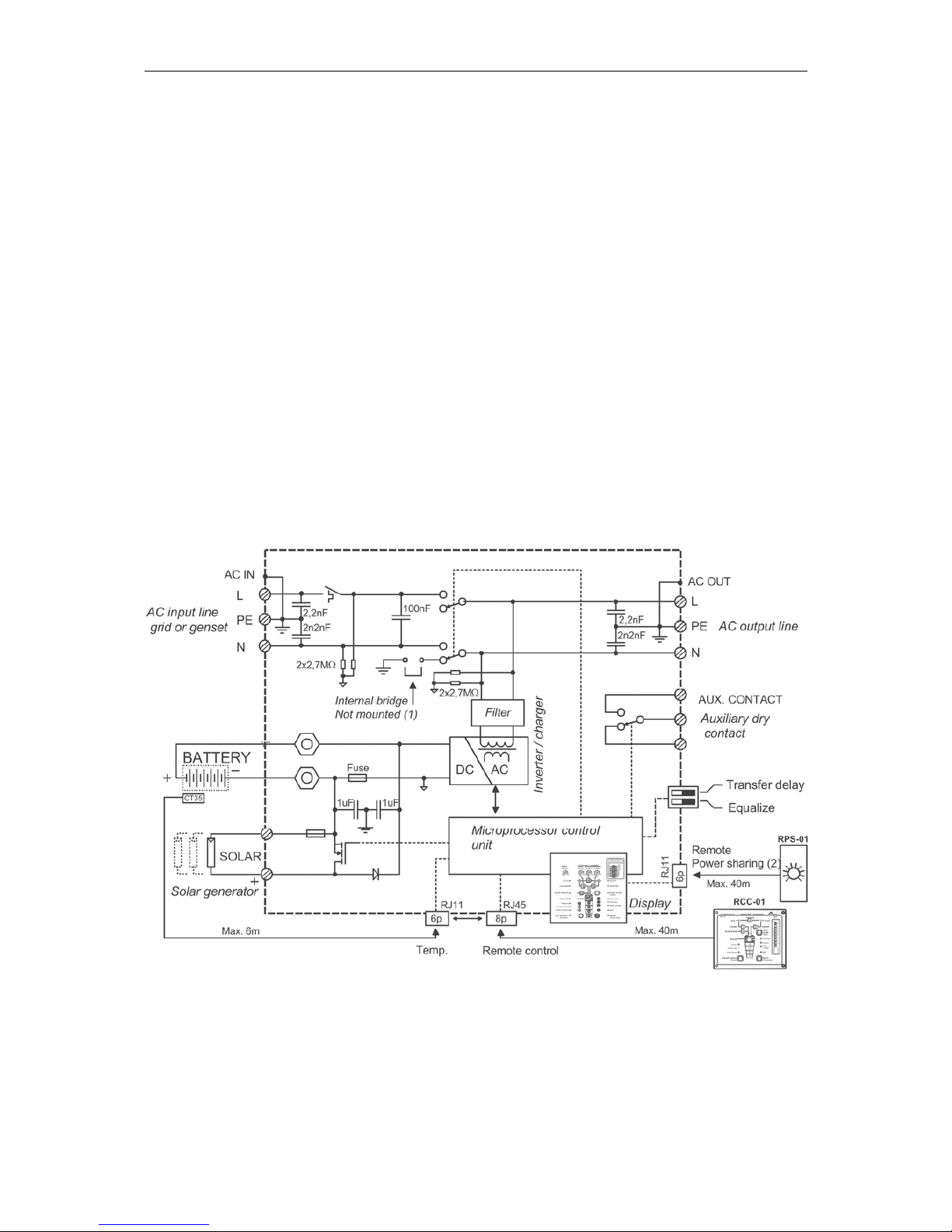
2.1 Principle schematic
Page 8

STUDER Innotec COMPACT
COMPACT V6.6 8/83
Notes:
(1) The neutral of the appliance is not connected to the earth whatever the
function mode is. If requested and according to the local regulation, an automatic
connection between Neutral and earth in inverter mode only may be done by
installing a bridge internally to the unit. Please contact your installer regarding this
point.
(2) Remote control for remote adjustment of the input limit. (see chap. 4.6.3)
2.2 Description of the main functions
2.2.1 The inverter
The sine wave inverter COMPACT generates a sinusoidal AC voltage with an
exceptionally precise voltage and stabilized frequency. In order to start large electric
motors, the user has the possibility to use a short surge power which is 3 times the
nominal power of the COMPACT.
The inverter is protected against overload and short circuit. A power stage with the
latest MOS-FET power transistors, a toroidal transformer, and a fast regulating
system makes a robust and reliable inverter with the highest efficiency. A 1-20 Watt
adjustable charge detection system allows the smallest energy consumption and
ensures a long life for the battery.
2.2.2 The transfer system
COMPACT can be connected to an AC source. For example a stand-by emergency
generator or the AC network. With the transfer system, on one side you have an
alternating voltage at the output for the use of consumer appliances. On the other
side the battery park is being charged. The distribution of energy between the
consumer appliances and battery charger is automatic.
2.2.3 The battery charger
The built-in battery charger is so designed that it can charge the battery quickly and
fully. A microprocessor controlled, Step charging process, ensures the optimal
charging of the battery. The desired charging current can be set continuously from 0
to 50/55 A, as per the model. The setting is made accordingly to the battery capacity
and power available.
The battery charger is designed for lead-acid and lead-gel batteries. Thanks to the
floating charge system the batteries can remain continuously connected.
2.2.4 The solar charge controller (optional)
With the built-in solar charge controller, the COMPACT is a complete solar-powercenter. In a solar installation this controller ensures that the batteries are charged
correctly. With the COMPACT, batteries can be charged with a generator and with
the solar modules at the same time. The charging of batteries with both energy
sources is carried out fully automatically.
2.2.5 Remote control
As an option, a remote control RCC-01 can be connected to COMPACT. All
operating features and displays, save the adjustment levels (22/23/24/26), are
available on the re-mote control. It is supplied with a 20m long cable. This cable can
be up to 40m long. On the remote control, output power and charging current are
also displayed.
Page 9
STUDER Innotec COMPACT
COMPACT V6.6 9/83
2.2.6 Remote control for Power Sharing
This remote control RPS-01 can be connected to the COMPACT in the dedicated
plug. The maximum current available from the energy source can be adjusted by the
turning button.
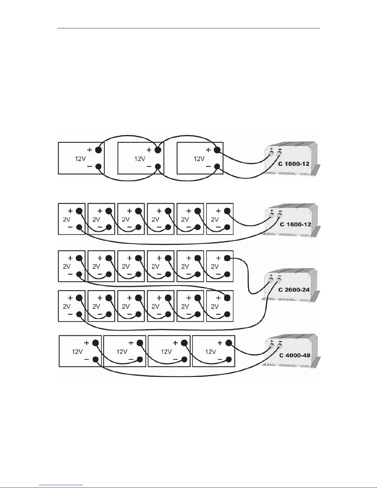
2.3 Battery connecting
Lead-acid batteries are normally available in blocks of 2V, 6V or 12V. In most cases,
to generate the necessary operating voltage and the capacity of the batteries for the
COMPACT many batteries have to be connected together in parallel and or in series.
Here are 3 examples of connection:
2.3.1 Connection in parallel
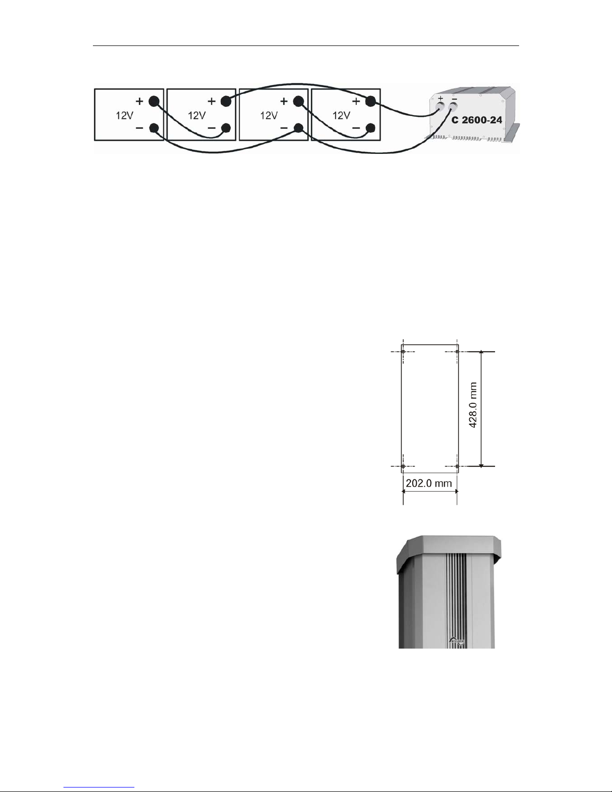
2.3.2 Serial connection
Page 10
STUDER Innotec COMPACT
COMPACT V6.6 10/83
2.3.3 Serial and parallel connection
3 Mounting and installing
3.1 Installation place
The location of the COMPACT must be driven by the following criteria:
Protection from unauthorized handling
Dry dust free room, no condensation
Never install directly over the battery and never in a cabinet together with the
batteries
Keep ventilation holes free
In mobile installations it is important to keep the vibrations down as low as
possible
3.2 Fixing
3.2.1 Fixing the COMPACT
Basically the COMPACT can be installed in any
desired location. Preferred is that the appliance be
wall mounted with battery cables downwards. The
COMPACT must be fixed directly on a flat, surface,
with four screws through the four holes (diameter
5.5mm) which are accessible from the outside. In
motor vehicles, the COMPACT must be fixed on a
flat plate itself fixed on vibrations reducing elements.
The COMPACT must not be fixed on a combustible
base, as the back of the casing can get hot and
reach up to 80 degree Celsius.
3.2.2 Protection cover IP-23
This cover IP23 (Order ref. CIP-23) can be easily
installed after the fixation of the COMPACT. For
that release a little the too screws down and more
the tow up. Then it’s possible to pass the IP 23
cover between the COMPACT and the wall. The
cover must touch the screws. Lock on the four
screws, it’s ready.
Page 11

STUDER Innotec COMPACT
COMPACT V6.6 11/83
3.3 Connections
3.3.1 General instructions on connecting
The cable connection on the terminals AC INPUT / AC OUTPUT / 16A 230VAC
are carried out with a screwdriver Nr.1 and the connection on the SOLAR
terminal with a screwdriver Nr.2.
The conductor cross section on the terminals AC INPUT / AC OUTPUT / 16A
230VAC of the connecting cable must be minimum 2.5mm2.
All connecting cables and also the mounted battery cables, must be fixed with
strain relief clamps.
The COMPACT is delivered with battery cables already connected.
The battery cables must never be extended. If the extension is unavoidable then
the conductor cross section must be elevated accordingly.
To protect the battery cable, a fuse corresponding to the conductor cross
section must be fixed directly on to the battery.
All cables must be tightly screwed in place. For safety, a yearly control is
recommended. In mobile installations control must be carried out more often.
Connecting must be done by qualified personnel. Material such as cable,
connectors and distribution boxes, fuses etc. used in the installation must
comply with the respective valid low-voltage installation rules and regulations.
3.3.2 Protection cover of the terminals connections
The protection is available as an option (Order ref.
CFC-01) to avoid to do accidental and hazardous
contact on the terminals 230Vac if the unit is monted
in a non restricted area. It mounted with strain relief
clamps for the cable.
Page 12
STUDER Innotec COMPACT
COMPACT V6.6 12/83
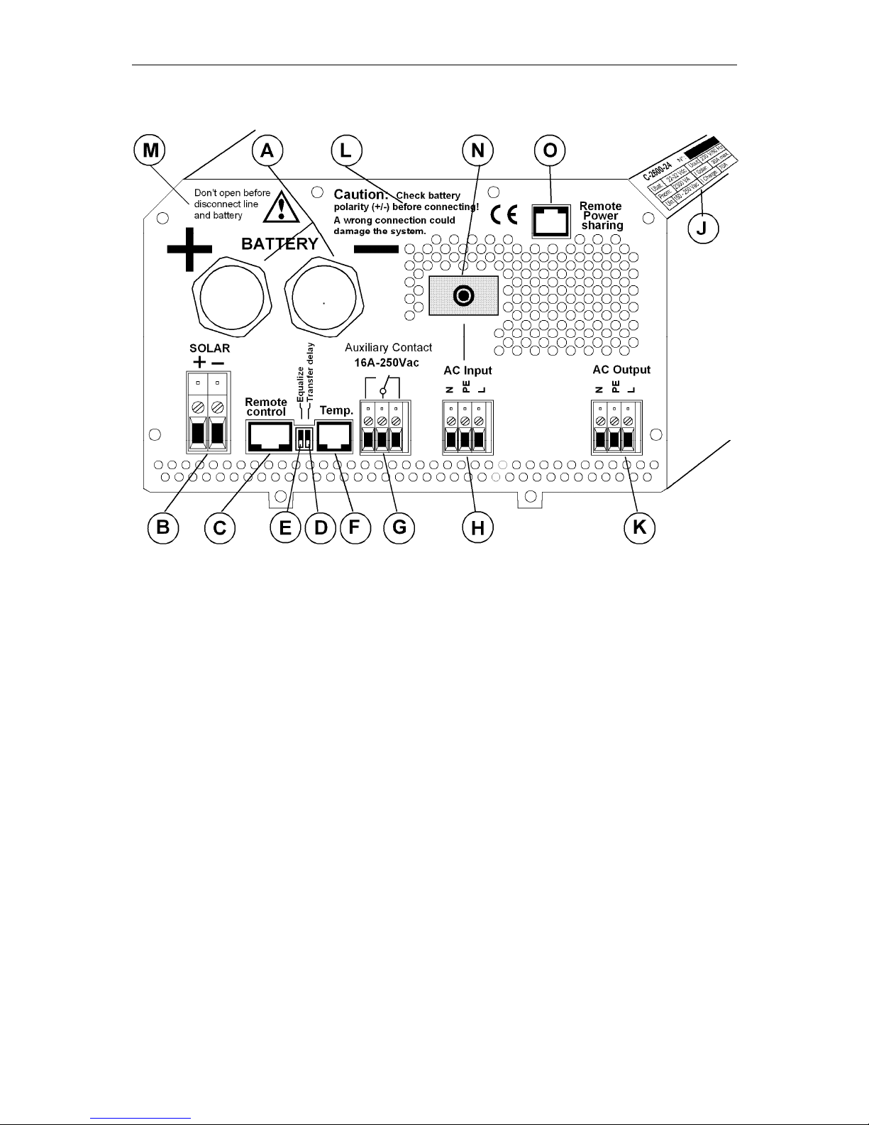
3.4 Connection Plan
A Battery +/- Battery cable (already installed)
B SOLAR +/- Connection terminal for Solar modules
C Remote contr. Connection terminal for Remote Control RCC-01
D Delayed transfer Slide switch to delay the opening of the transfer swich
E Equalize Slide switch for equalization of the Battery
F Temp. Connection terminal for Temperature sensor CT-35
G Aux. Contact Connection terminal for Auxiliary Contact
H AC Input Connection terminal for AC-input. Located directly
above this terminal is the automatic safety cut-out for
this terminal.
J ID Plate Identification plate with Technical data and Serial
number
K AC Output Connection terminal for AC-output
L Caution… Caution: Check Polarity (+/-) before connecting the
battery !
M Don’t… Do not open without disconnecting all terminals
N 16A Protection 16A Protection switch for the Transfer system
O Remote Power Sharing Input current repartition
Page 13

STUDER Innotec COMPACT
COMPACT V6.6 13/83
3.5 Cabling
Connecting the COMPACT is a very important step of the installation. You must take
care that all connection work is carried out in a clean and correct way and that under
no circumstance a cable is connected to a wrong terminal.
Connecting of the COMPACT must be carried out in the following order. In case of
dismantling this order must be reversed.
3.6 Pre-installation settings
Before you start with the cabling of the COMPACT you must set the type of battery.
In case sealed-gel batteries are used then you must set the small slide-switch
„Equalize“ which is on the front with the connection terminals, in OFF position. In
case of „normal“ lead-acid – batteries, these can handle a higher equalizing charge,
the same slide switch can be set in ON position. In case of doubt leave the setting in
OFF position.
This will allow an equalizing cycle (higher end of charge voltage) during the next
charge process. Since then equalizing will occur every 25 usual cycles.
3.6.1 Connection to battery
Get the batteries ready for connection: Matching battery terminals, matching fuse on
a clamp. Prepare battery cables, if necessary press on cable tabs/shoes. Connect
red cable on Plus (+)-Pole and the black cable on the Minus (-) Pole. On connecting
the second cable to the battery pole a spark is produced, because for a short time
high current flows in the COMPACT to charge the capacitors. For this reason follow
strictly the safety measures described in this manual. Check if the red LED OFF (13)
is lit. If it is not lit, press shortly on the switch ON/OFF (19), now OFF should be lit.
On connecting the battery the COMPACT needs 1 – 2 Minutes to calculate the actual
capacity of the battery. During this time the battery condition is shown as 100%
charged. (LED 14 – 17 lit).
If the LED 12 Battery Low/High is lit, the battery charge is too low. If the LED 12
Battery Low/High is blinking, the battery charge is too high.
Caution: With a wrong battery voltage the COMPACT can be destroyed. (for
example: connecting a C 1600-12 to a 48V-Battery).
Nevertheless, if the COMPACT had been connected with reverse polarity, it is highly
probable that the fuse inside the casing is defect. Before opening the casing cover all
terminals must be disconnected including the battery. If the COMPACT does not
function after the changing of the fuse and correcting of the polarity, it means that it is
defect and must be sent for repair.
3.6.2 Connection to the 230Vac-consumer appliances (AC OUTPUT)
The 230V consumer appliances must be connected to the terminals AC OUTPUT
with cables which cross section has to follow the local rules in force (usually
2.5mm2). Connections are marked as follows “N“ Neutral, “PE“ Earth (connected to
the appliance case), “L“ Live.
Caution: High voltages can be there. Make sure that the COMPACT is turned off
(LED 13 lighting) before the connection.
3.6.3 Connection to the 230Vac Input (AC INPUT)
The 230V-supply from network or from a generator must be connected to the input
terminals AC INPUT with cables which cross section depends on the power source
(usually 2.5mm2). Connections are marked as follows: “N“ Neutral, “PE“ Earth
(connected to the appliance case), “L“ Live.
3.6.4 Connect the solar modules: SOLAR +/- (Only for solar option)
Page 14

STUDER Innotec COMPACT
COMPACT V6.6 14/83
Solar modules are connected on these terminals. Under no circumstances should
any other energy source i.e. wind generator be connected to these terminals! Only
solar modules must be connected with two cables +/-. Depending on the power of the
modules, the cable cross section should be 2.5 up to 6mm2. Before connecting it is
necessary to check with a Voltmeter that the voltage of the Module meets the
following values:
C 1600-12 17-25V/30A, C 2600-24 34 – 45V/30A,C 4000-48 68 – 90V/20A.
3.6.5 Connection to Auxiliary Contact
This contact is a potential free change over contact the currents and voltages allowed
for this contact are max. 16A/250Vac. The LED 5 “Contact active” shows the position
of them: alight mind active and off mind non-active. The schematic view of the
connections on the front, show the relay in the non-active mode.
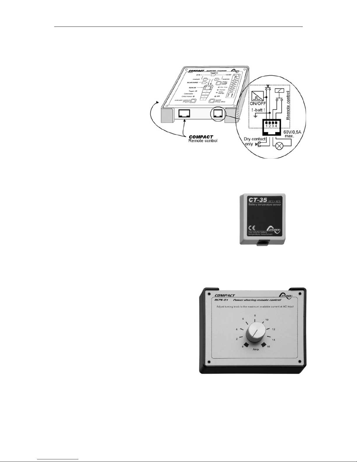
3.6.6 Connection to Remote control
The Remote Control RCC-01 is connected in the terminal marked „Remote control“
with a 20m long cable and a RJ11/8 connector. The Remote Control can be plugged
IN or plugged OUT during any operation situation. Push in the connector softly until
you hear the „click“ showing that the connector is locked. The same applies to the
plug in the Remote Control.
The length of the cable for Remote Control should not exceed 40m. We deliver it with
20m cable.
3.6.7 Connection to Temperature Sensor (Temp.)
The temperature sensor CT-35 is connected in the terminal marked „Temp“ with a
3m long cable and a RJ11/6 connector. The temperature sensor can be plugged IN
or plugged OUT during any operating situation. Push in the connector softly until you
hear the „click“ showing that the connector is locked. The temperature sensor must
be glued to the wall of the battery or near it. The Temperature Sensor cable must
not be tied together with the battery cables or laid in a rope/bundle.
3.6.8 Connection to the Remote Control for the „Power Sharing“ (RPS-01)
This remote control is connected with a 20m long cable to a RJ11/6 plug. It can be
connected and disconnected at any time. Push in the connector softly until you hear
the „click“ showing that the connector is locked.
Page 15
STUDER Innotec COMPACT
COMPACT V6.6 15/83
4 Control
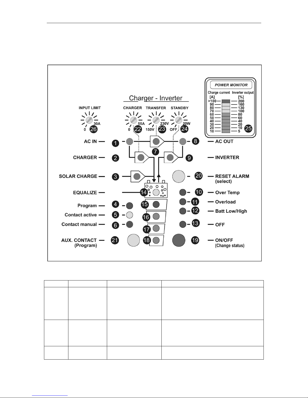
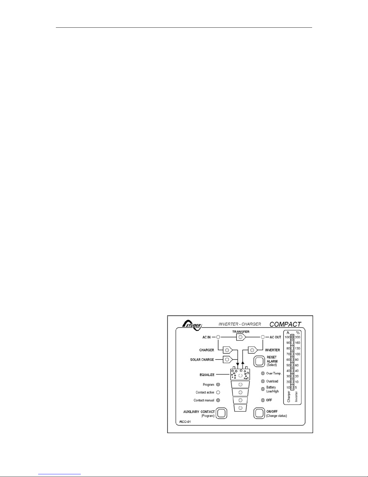
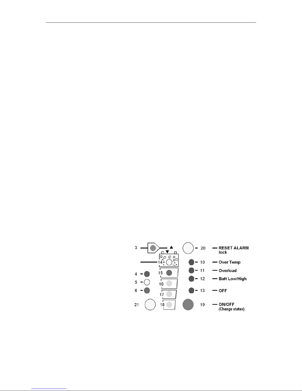
4.1 Display and control parameters
4.2 Light Emitting Diodes (LED)
LED Marking LED lit LED blinks
1 AC IN
Voltage
corresponding to
self-adjusted
values is at the AC
IN input.
A voltage outside the self-adjusted
values is at the AC IN input, or the
COMPACT is in synchronization
phases
2 CHARGER
Battery charger is
working
The battery charger is locked OFF
(see chap. 4.6) or provisory out of
order. In that last case it will restart
within 10 seconds
3
SOLAR
CHARGE
Connected solar
modules are
Page 16
STUDER Innotec COMPACT
COMPACT V6.6 16/83
delivering energy
4 Program
Program mode for
Aux. Contact
5
Contact
active
Auxiliary Contact is
activated
6
Contact
manual
Aux. Cont.
manually activated
7 TRANSFER
Transfer system is
active. In- coming
voltage is being
sent directly to AC
OUT outlet
Transfer (bypass) is disabled (see
chap. 4.7)
8 AC OUT
There is a voltage
at the AC OUT
outlet
The Inverter is in Standby-Mode
9 INVERTER Inverter is working Forced Inverter Mode (see chap. 4.5)
10 Over Temp.
For the time being
the COMPACT is
out of service
because of
overheating.
11 Overload
The COMPACT is
out of service
because of
overload or shortcircuit
12
Batt.
Low/High
Battery voltage is
too low
Battery voltage is or was to high
13 OFF
COMPACT is
turned off. Turning
it back on is only
possible manually.
COMPACT is for the time being
turned off. Turning it back on will
follow automatically !
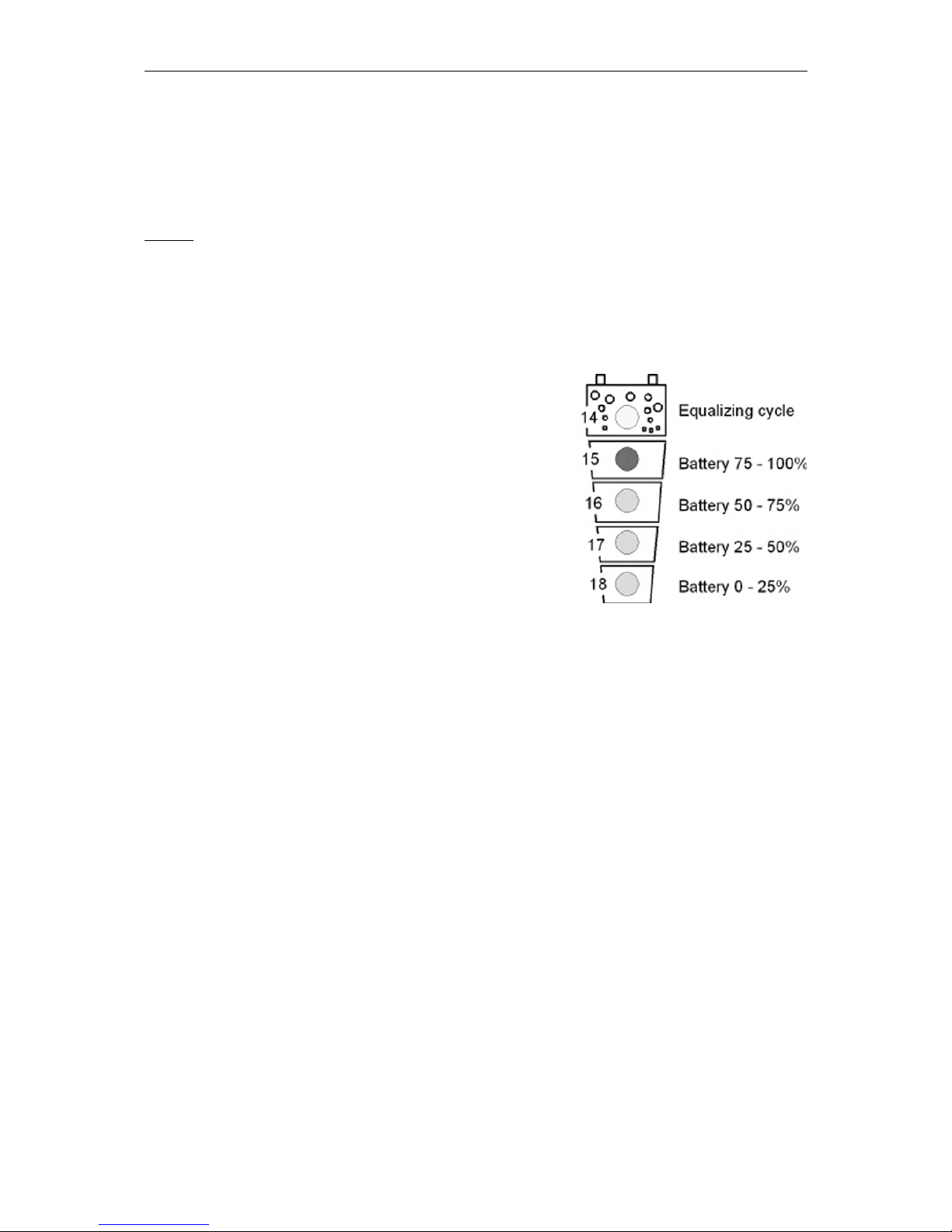
14 EQUALIZE
Battery equalizing
is set
15–18
State of charge of
the battery
LED 15 – Absorption time is running
25
POWER
MONITOR
Display the value of the output power in % of Pnom (in
Inverter Mode) and the charge current in Amps (in Charger
Mode). In this mode the red LED indicates that power
sharing is in use (>100A).
4.3 Push buttons
19 ON/OFF
Turning the COMPACT on and off (Help Button for
Programming)
20 RESET Alarm Signal off (Help Button for Programming)
21 Aux. Contact Control Aux. contact (Help Button for Programming)
4.4 Turning Knobs
Page 17

STUDER Innotec COMPACT
COMPACT V6.6 17/83
22 CHARGER Adjustment for max. Charging Current
23 TRANSFER
Adjustment for Transfer Voltage Threshold (TRANSFER –
INVERTER)
24 STANDBY Adjustment for „Standby“ system
26 INPUT LIMIT
Must be adjusted to the maximal available current of your
AC INPUT supply
4.5 The Inverter
An Inverter is built in the COMPACT, which generates a sinusoidal alternating
voltage of a very high quality. With this Inverter any 230Vac alternating voltage
appliance up to the nominal power of your COMPACT can be operated. Thanks to
the generous dimensioning of the COMPACT, you can operate appliances requiring
higher power than the nominal power of the COMPACT for a short time. The
COMPACT provides up to 3-times the nominal power to start motors.
The Inverter mode is displayed through LED 9 (Inverter). If the Inverter Mode is
disabled (see chap. 5.5) LED 9 will blink. If the LED 9 is lit, the Inverter is in operation
and you have 230Vac at the output AC OUT. The actual power of the connected
appliance is displayed on the power monitor 25 and on the Remote Control.
4.5.1 Charge detection system „Standby“
In order to avoid unnecessary discharge of the battery, the inverter switches OFF
automatically if no appliance is connected and switches ON automatically again if
appliance is connected. The LED 8 blinks if the inverter is in Standby-Mode. The
switching-on/starting level can be adjusted with the turning knob 24 „STANDBY”.
Adjusting the switching-on level is as follows: Switch off all consuming devices, turn
the Turning Knob 24 to the right until the LED 8 is blinking, switch on the smallest
consuming device (i.e. Mobile phone charger), turn the Turning Knob slowly to the
left until LED 8 is lit.
If the Standby-Mode is not wanted, turn the Turning Knob 24 to the left, to the OFF
position.
4.5.2 Overload
If the Inverter is too long or too heavily overloaded, it switches off. The LED 11
„Overload“ is lit and LED 13 „OFF“ blinks. After ca. 10 seconds the Inverter switches
on automatically. If the Inverter is overloaded four times one after another in a short
time, then it no longer switches on automatically. The LED 13 remains lit. Press the
push button 19 „ON/OFF“ in order to switch on the Inverter.
4.5.3 Overheating (Over Temp.)
If the Inverter has been overloaded for a long time or it has been working in too high
surrounding temperatures, it will switch off. The LED 10 „Over Temp.“ is lit and the
LED 13 „OFF“ blinks. After cooling down, the inverter switches back on automatically.
One minute before the inverter switches off for too high temperature it gives out an
acoustic alarm signal. If the Auxiliary Contact has been programmed to detect the
high temperature then it synchronizes the relay with the alarm signal. In this way, for
example, an emergency back- up system can be started without any break in the
energy supply.
4.5.4 Battery Condition
Deep discharge of the lead-acid batteries leads to high losses in capacity and early
aging. That is why the battery condition is continuously controlled and supervised.
With low volt-age the inverter switches off. The LED 12 „L/H Batt.“ is lit and the LED
Page 18
STUDER Innotec COMPACT
COMPACT V6.6 18/83
13 „OFF“ blinks. When the battery voltage gets up to 12.1V / 24.2V / 48.4V, the
Inverter switches on automatically. One minute before the Inverter switches off due to
low voltage it gives out an acoustic alarm signal. If the Auxiliary Contact has been
programmed to detect the low voltage then it synchronizes the Aux. Contact with the
alarm signal. In this way, for example, an emergency back up system can be started
without any break in the energy supply.
The low voltage is set to 11.6V / 23.2V / 46.4V. These settings are standard for most
batteries. These voltage levels are maintained by the built-in Battery-ManagementSystem of the COMPACT by matching the load and the battery condition.
This setting is comparable with the levels of 10.8V/ 21.6V / 43.2 which are given
for most batteries at nominal load.
All voltage levels can be programmed. See the instructions under the section on
Programming. Check with your battery supplier which voltage values should be set.
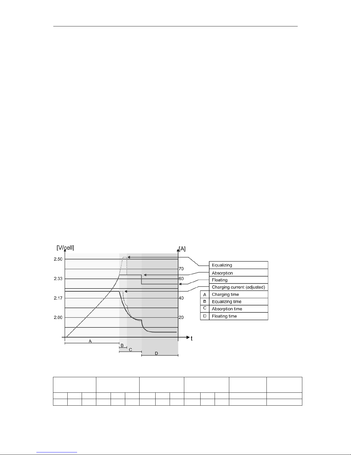
4.6 The battery charger
4.6.1 Cycle of charge
The full automatic COMPACT Battery Charger is adjusted at the factory so that most
lead-acid and lead-gel batteries can be charged to the maximum. As soon as the
minimum alternating voltage for the AC IN set on the Turning Knob 23 is available at
the input (LED 1 AC IN is lit), the Battery Charger is switched on automatically (LED
2 CHARGER is lit). The battery is fully automatically charged matching to the charge
level, the adjusted volt-age levels and the charge current. Thanks to the built-in Float
Charge System, the batteries can be left connected for unlimited time with the
Battery Charger switched on.
During the charging phase the appliances at the outlet AC OUT are continually
supplied with power (LED 8 AC OUT is lit).
The charger functions are shown in the following diagram:
4.6.2 Default values for battery voltage thresholds
Low voltage Float charge Absorption Equalization
Absorption
time
Equalization
time
12V 24V 48V 12V 24V 48V 12V 24V 48V 12V 24V 48V 12/24/48V 12/24/48V
11.6 23.2 46.4 13.5 27.0 54.0 14.4 28.8 57.6 15.6 31.2 62.4 2h 20’
These values can be modified by mean of the optional remote control
Page 19
STUDER Innotec COMPACT
COMPACT V6.6 19/83
4.6.3 Equalization charging
Before you program the COMPACT for Equalization-charge you must check with
your supplier that the batteries are suitable for this process.
Equalization is recommended for the lead-acid batteries in order to mix well the
electrolyte fluid and to clean the lead plates.
If the COMPACT is operating with a lead-acid battery, which is suitable for
equalization, the slide switch „Equalize“ which is on the cable connection side, must
be placed in the ON position. In this setting, every 25 charge cycles an equalization
is carried out for 20 minutes (factory setting). During such a charge cycle the LED 14
is lit and during equalizing it is blinking. Charge cycle with equalization can be started
independently from the actual program. For this purpose the slide switch must be slid
from “OFF” to the “ON” position. The LED 14 will light up. If the periodic equalization
is not required, slide switch must be slid back to the „OFF“ position after the
completion of the manual cycle.
The equalizing voltage can be changed. How to proceed is explained in chap. 5.3.
Batteries not designed for equalize should never been charged this way.
CAUTION: During the equalization process, the batteries produce a lot more
gas. DANGER OF AN EXPLOSION !! The battery room must be well ventilated.
Equalization mode should never be used when using Gel-Batteries.
4.6.4 Input current repartition (Power sharing)
To manage the power available on the AC INPUT (depends on the supply use) the
COMPACT is equipped with a system usually called “Power sharing” or INPUT power
distribution. With this function it is possible to limit the AC INPUT current assigned to
the charger. The more current it uses on the OUTPUT the less it gives to the charger.
Priority to the OUTPUT. When the power sharing is used the LED 200% (red) is lit to
point out that the charge is limited.
Caution: if the power use on the OUTPUT is higher than the value of the INPUT
LIMIT (26) the COMPACT cannot limit the current, then the generator means to
stop or the circuit breaker means to break before.
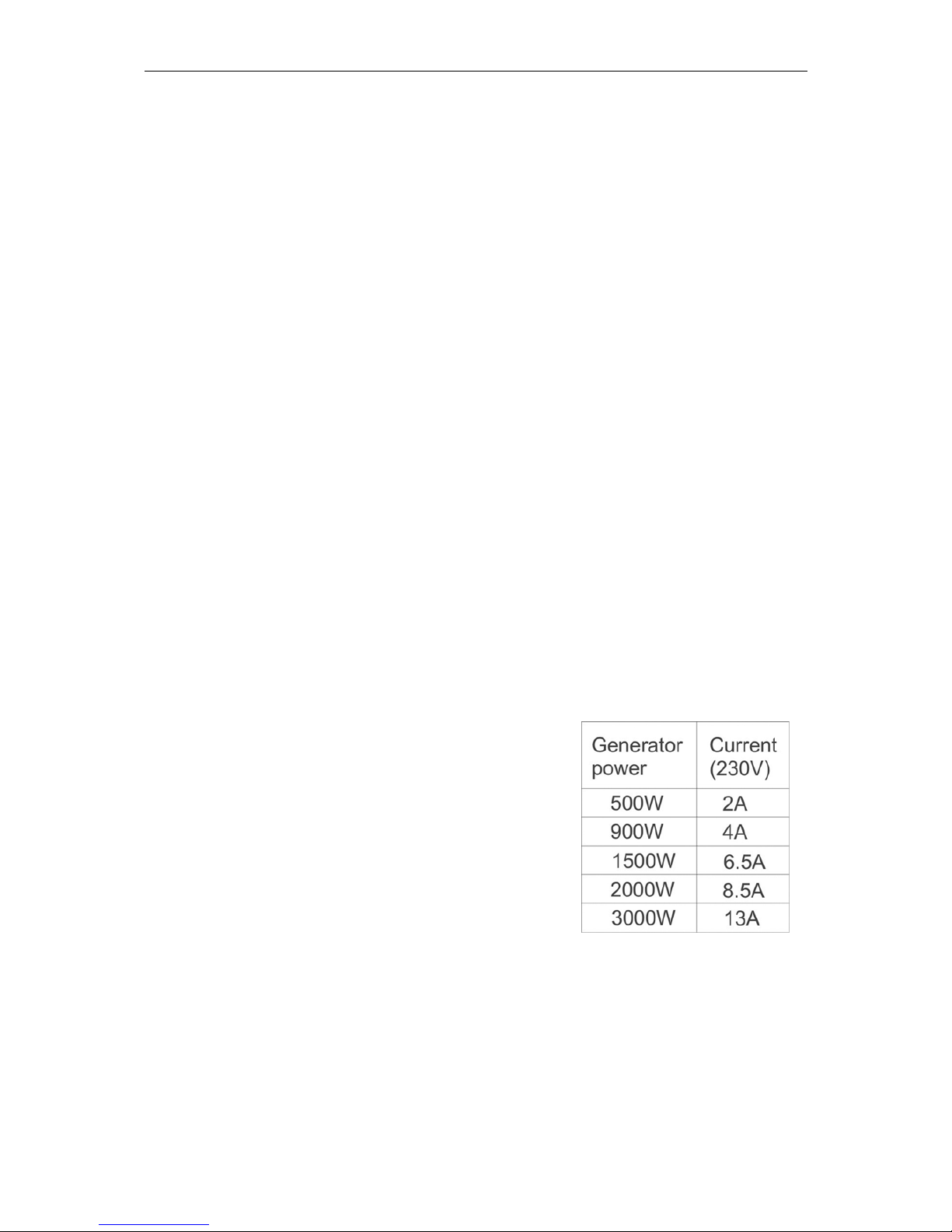
4.6.5 Set the INPUT LIMIT (26)
The current available for the COMPACT depends on
the supply used from a motor generator, the network
of a camping or of a shore connection. The value of
the turning knobs INPUT LIMIT (26) must be adjusted
lower or equal to the current available from the
source.
For example if you have a generator of 2kW you must
adjust the turning knobs 26 to a max. 8.5A. To
calculate this, one divides the nominal power (2000W)
by the voltage (230V). If you have a circuit breaker
(i.e. 6A) before the COMPACT, then you set this
value on the turning knobs (26) (i.e. 6A).
This adjustment can be done remotely with the optional RPS-01 (see section 3.6.7).
In that case the smallest values will be taken into account.
4.6.6 Charging current
The maximum charging current for the battery can be adjusted with the Turning Knob
22 (CHARGER). The charging current of the battery should be set to approximately
10 – 20% of the battery capacity (at C10). This means that the charging current for a
battery with 300Ah should be set between 30 – 60A.
Page 20
STUDER Innotec COMPACT
COMPACT V6.6 20/83
The charging current is displayed on POWER MONITOR (25) of the front panel
or on the Remote Control.
4.6.7 Battery Condition
Built-in microprocessor with a specially developed algorithm calculates the actual
state of charge of the battery and displays it on LED 15 – 18. The LED 14 is lit when
the system is carrying out a charge cycle with equalization.
Notice: the exact measure of the battery state of charge with electrical parameters is
al-most impossible. The display of the state of charge is always more or less precise.
The measure system built in the COMPACT takes into account the battery voltage,
the discharge and charge current as well as the undulation of the voltage. If the
battery and the COMPACT are used according to their technical data, the battery
state of charge is displayed accurately. In the following cases of use the display can
diverge:
Battery charge or discharge with too high
currents
Battery cable cross section too small
Battery connections badly tightened or corroded
Charge of the battery with external battery
charger
Discharge of the battery with users not
connected to the COMPACT
Work with defective or sulphated batteries
This means that the display can, within few minutes
during the charge, commute from 25% to 75% or
during the discharge, to the opposite direction.
As many of the working cases mentioned above often occur, the measure system of
the COMPACT takes into account, during the charge, only the peaks of the voltage
undulation. As a consequence, the battery voltage at the start of the absorption
stage, measured by a voltmeter will appear deeper. By decrease of the charge
current the voltage will reach the exact values.
For safety reasons, you must get the recommended charge voltage and charge
currents from your battery supplier. The voltage levels and charge characteristics can
be changed through Programming. The instruction for programming of battery
charger is in the section „Programming“ (Chap. 5.3). The correct charging is
mandatory for a safe function and a long-life of the battery.
The battery charger functions are described by the graphic in chap. 4.6.1.
4.7 The Transfer system
When an AC voltage is at the input AC IN of the COMPACT, the LED 1 AC IN is lit.
When this voltage matches the lowest adjusted value set by the Turning Knob 23
TRANSFER, and the frequency is between 44Hz and 65Hz, this voltage is switched
directly to the battery charger and to the output AC OUT. The LED 7 TRANSFER is
lit. The inverter is switched off and the battery charger switched on. This process is
automatic, unless the charger mode or the transfer mode is disabled (see Chap. 5.5).
The maximum current of the Transfer switch is 16A. That means through this system,
consuming devices up to a maximum of al 3700 Watt can be operated. When the
Battery Charger is working, part of this power is used for charging according to the
power sharing system.
Page 21

STUDER Innotec COMPACT
COMPACT V6.6 21/83
The Transfer system is protected against overload with a circuit breaker on the AC
Input side of the COMPACT. If the system has been overloaded, the button/pin of the
fuse will pop out. To put the automatic safety system back in to operating you must
push this pin back.
Note: in the Inverter operation, The COMPACT generates a true sinusoidal and
quartz stabilized output voltage. However if the COMPACT is supplied from a grid or
a generator and the transfer contact is active, then you have at the output AC OUT
the same voltage as that at the input. This voltage can not be modified by the
COMPACT !
4.7.1 Set the transfer voltage threshold
The voltage threshold of the transfer can be adjusted between 150 to 230V with the
turning knobs (23). From factory this value is 200V. Most appliances can work on this
voltage. When the Input voltages reach the selected value on turning knob, the
inverter switches off and the AC INPUT goes directly on the AC OUTPUT. When the
voltage INPUT is less of 20V the value set, the transfer is stopped and the OUTPUT
switches back on the inverter.
Note : Don’t use the turning knobs “TRANSFER” (23) to adjust the AC OUTPUT
voltage ! This is only it’s only a voltage threshold level to enable or disable the
transfer.
4.7.2 FAST (UPS)- MODE for the Transfer Switch
The quick and break free Transfer mode is programmed with a slide switch „Transfer
Delay“ OFF, which is on the front side (cable connections side).
The aim of the COMPACT is to supply the appliance with a break-free alternating
voltage. When the incoming voltage AC IN no longer matches values which have
been set with the Turning Knob 23, the inverter switches on at once. The transfer is
carried out in 0.02 seconds. This quick transfer ensures a break-free function for
most appliances. If you have an alternating voltage back at the input AC IN, transfer
system starts up again with-out any break, and the inverter is stopped.
4.7.3 Delayed mode of the Transfer System
The delayed mode of the transfer system is programmed with the slide switch (D) on
front plate under the battery connection.
The COMPACT provides a break-free alternating voltage for the appliance. A quick
transfer switch is not always sensitive nor is it always desired. For example, when the
appliances are operated by a small back-up generator. An overload of a short period
on such a generator, i.e. start of a vacuum cleaner etc., has the effect of decreasing
the voltage for a short time. As in such cases the transfer to the Inverter is not
desired, the transfer system can be programmed with a delay. When the slide switch
“Transfer delay” (D) is in the „On“ position, the transfer to the inverter takes place
with a delay of 5 seconds. If the voltage falls below 100Vac, the transfer takes place
without delay! The transfer switching to the Inverter takes place without any break.
4.8 The Solar charge controller (option)
The COMPACT also has a Solar Charge Controller built in. For charging the
batteries, Solar modules can be connected to the screw terminal SOLAR +/-. The inbuilt controller is a „Shunt controller“ for the maximum input current of 30A for C
1600-12 and C 2600-24 and 20A for C 4000-48. The operating voltage of solar
panels to be connected must match the actual operating voltage of the COMPACT
and never exceeds the max. rated value.
Under no circumstances should any other systems such as wind-generator be
connected at the input of the Solar Charge Controller.
Page 22
STUDER Innotec COMPACT
COMPACT V6.6 22/83
The Solar Charge Controller works automatically and is always in operation. As soon
as the energy is delivered from the Solar Charge Controller, LED 3 “SOLAR
CHARGE” is lit and the batteries are being charged. The Solar Charge Controller
works even when the Battery Charger is functioning. The way of working is the
principally the same as that of the Battery Charger. The function is described in the
section on Battery Charger. The programming and the adjustments are carried out in
accordance with the same conditions. Check with your battery supplier which
adjustments must be carried out for your battery.
4.9 The Multifunctional Contact
In the COMPACT there is a built-in programmable power relay. The potential-free
change-over contact (NO – NC) of this power relay is connected to the screw
terminal AUX CONTACT.
Maximum Contact load: 230Vac / 12Vdc / 24Vdc / 16A !
> 36Vdc / 3A !
With the Push Button 21 „AUXILIARY CONTACT“ the contact can be manually
switched on or off independently from programming and from the operating situation.
The LED 5 “Contact active” shows the status of the contact. The drawing up the
screw terminal “AUX CONTACT” is the inactive position mode, LED 5 “Contact
active” off.
The switching on and off of this contact can be freely programmed for every
operating situation of the COMPACT witch situation is indicated with a LED. There is
no limitation to its application and it is left to your wishes as to where and how you
would like to use it. The example and the setting of this contact are explained in
chapter 5.4.
In factory we program this for a dysfunction alarm. The contact is active when one of
these situations is detected:
Over temperature (LED 10 lit)
Overload (LED 11 lit)
Over or less voltage of batteries (LED 12 lit or blinking)
COMPACT is turned off manually or with a fault (LED 13 lit)
In case this function is not wished, it must be modified by programming according to
procedure in chap. 5.4.
4.10 The Remote Control RCC-01
As an option, a Remote Control
can be connected to the
COMPACT. All operating controls
and displays except from level
adjustment are available on the
Remote Control. The Remote
Control is supplied with a 20m long
cable. It can as long as 40m. The
Remote Control is sui-table for
surface mounting on the wall or on
to a switch board. It is fixed with 4
screws. The COMPACT can also
be programmed with the Remote
Control. The Programming is
descry-bed in the section
„Programming“.
Page 23
STUDER Innotec COMPACT
COMPACT V6.6 23/83
The output power and the charging currents are displayed on the Remote Control.
In the Remote Control there is an additional Alarm Contact and a built-in Control
Input. These two functions are available through Tip-jack RJ11/4 for use. This
Auxiliary Contact is Front / Work Contact (max. 0.5A!), which is independent from the
Auxiliary Contact of the
COMPACT. This con-tact is
active in case of an alarm of
the COMPACT.
The Control Input is connected
in parallel to the ON/OFFpush button. The COMPACT
can be switched on or off
through this input with an
impulse button or an impulse
contact.
Caution: No external voltage
should be connected to this
Input Control.
Order Number for Remote Control: RCC-01
Dimensions: H x B x T / 111.5 x 136.5 x 25mm
4.11 The Temperature sensor CT-35
Operating voltage of lead-acid batteries change depends
on the temperature. To correct the operating voltages
according to the actual temperatures, a temperature
sensor can be connected to the COMPACT.
The compensation through the sensor is –3mV/°C/Cell.
Order Number: CT-35
Dimensions: H x B x T / 58 x 51.5 x 22mm
4.12 Remote control for „Power Sharing“ RPS-01
If the Remote control RPS-01 is installed, the
Trimmer (26) “INPUT LIMIT“ has to be set on
the value max.. The COMPACT takes into
account the lowest values set on the inverter
and on the Remote control.
The current available at the COMPACT input
will be determined by the power of the
connected source (generator, grid etc...). The
potentiometer on the RPS-01 must be
adjusted lower or equal to max. value of the
power source.
For instance if the source is a generator of
2000 Watt, the potentiometer has to be set at
max. 8A. This value is obtained in dividing
2000 Watt by 230V. If the COMPACT is connected to a power source which is
protected by a 6A circuit breaker, the potentiometer must be set at a max. value of
6A.
Page 24
STUDER Innotec COMPACT
COMPACT V6.6 24/83
Caution: the COMPACT will not limit if an appliance draws more current than
available from the source ! This means that the connected generator will be
over-loaded or that the circuit-breaker before the COMPACT will break.
5 Programming
The COMPACT is equipped with a Flash processor fitted out with a Flash
memory, which means that even when it is disconnected from the battery, the
parameters that were programmed for the application remain after a new
connection to the battery.
It is possible to reinitialize (RESET) the COMPACT by pressing simultaneously
on the three push buttons 19/20/21 during at least 2 seconds. A beep will
confirm the RESET. The inverter switches off after this operation. It can be
turned on again after the beep. The programmed parameters will remain.
5.1 Standard setting
The COMPACT is delivered with the following default settings:
Auxiliary contact: active in case of defect or manual turn off with the LED 10/11/12/13
Battery voltage : Low voltage 11.6V / 23.2V / 46.4V
Float Charge 13.5V / 27.0V / 54.0V
End of Charge Voltage 14.4V / 28.8V / 57.6V
Equalization 15.6V / 31.2V / 62.4V
Absorption Time : 2 Hours
Equalizing Time : 20 Minutes
5.2 Reset value (default settings)
To come back to the default settings, press simultaneously on the push buttons
20/21 during at least 2 seconds. A beep will confirm the comeback to the factory
settings. The inverter switches off after this operation. It can be turned on again after
the beep.
5.3 Battery voltages and absorption time
5.3.1 Set the voltage and timing threshold
The programming is done in
accordance with the following
steps:
Push and hold down, the Push
Button 21 (Program) and the
Push Button 19 (Change status)
for minimum 2 seconds
simultaneously.
With the Push Button 20 (select)
select which of the battery level
and of the absorption time have
to be changed.
These four red LED’s show the function set:
Low voltage LED 13 (ON/OFF)
Float charge LED 12 (Batt. Low/high)
Absorption (End of charge) LED 11 (Overload)
Equalization LED 10 (Overtemp.)
Page 25
STUDER Innotec COMPACT
COMPACT V6.6 25/83
Absorption Time LED 10/11/12/13 (altogether)
With the Push Button 19 (Change status) set the desired parameter (voltage or time)
to modify (LED 14/ 15/16/17/18). Push Button 19 (Change status) to set the desired
value according to the table 5.3.2.
If desired, repeat the operation with any other parameter (voltage or time) to be
changed.
If during 30 seconds no buttons are pressed, the selected values are automatically
stored and the COMPACT switches back in to the normal operating status.
The voltage levels and times changed through programming are only first active with
the next charge cycle!
The voltage level which is not suitable can greatly reduce the battery life or
could even destroy it ! Therefore check beforehand with your battery supplier.
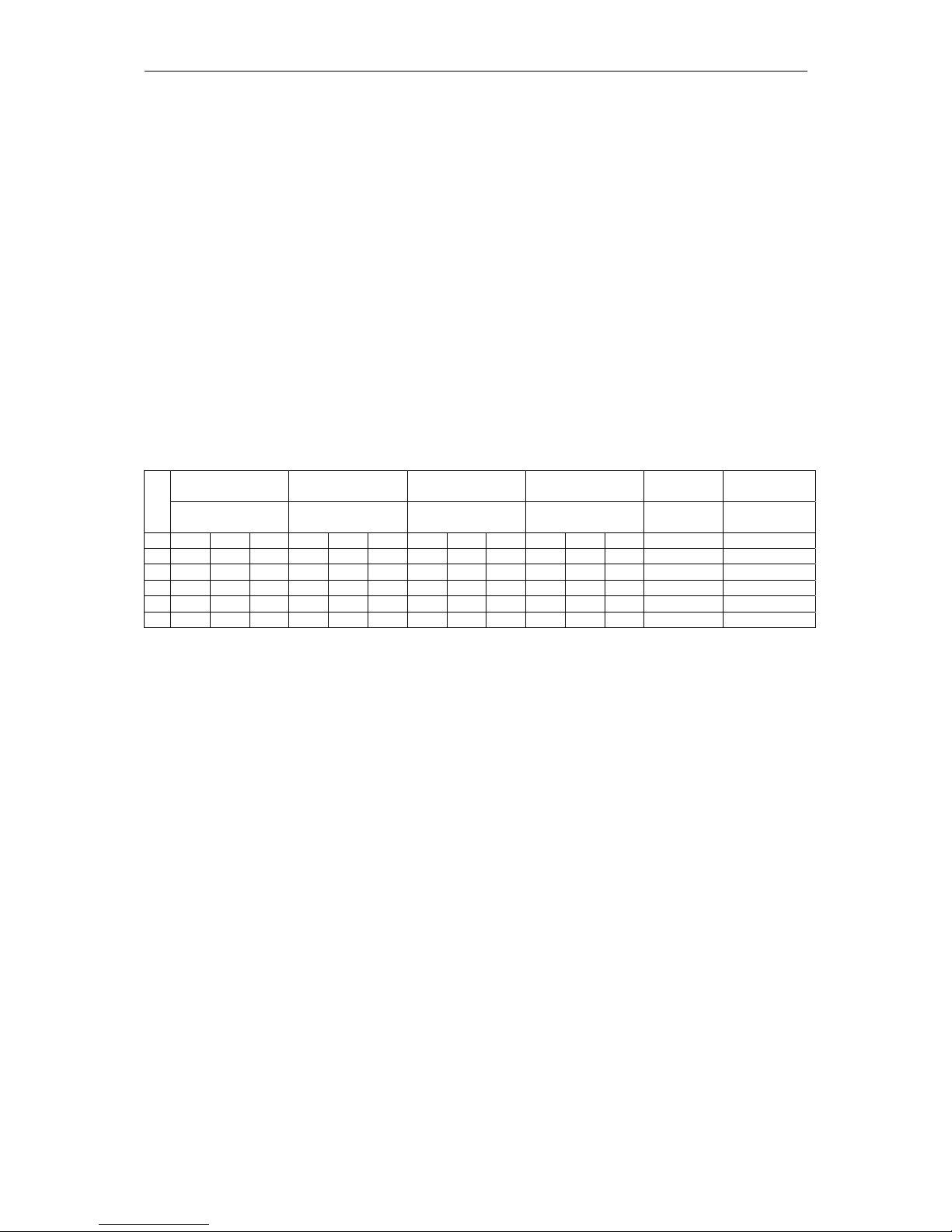
5.3.2 Table of voltage and timing threshold
The voltage levels (low voltage, float charge, end of charge and equalization) and the
duration of the absorption charge can be changed.
The display of these voltages and the times in the program mode are in accordance
with the diagram shown below:
LED
Low voltage Float charge Absorption Equalization
A
bsorption
time
Equalization
time
LED 13 LED 12 LED 11 LED 10
LED
10/11/12/13
LED 10/11
12 24 48 12 24 48 12 24 48 12 24 48 12/24/48 12/24/48
14
12.0 24.0 48.0 13.7 27.4 54.8 16.2 32.4 64.8 16.2 32.4 64.8 4h 3h
15
11.8 23.6 47.2 13.6 27.2 54.4 15.6 31.2 62.4 15.9 31.8 63.6 3h 2h
16 11.6 23.2 46.4 13.5 27.0 54.0
15 30 60
15.6 31.2 62.4 2h
1h
17
11.4 22.8 45.6 13.4 26.8 53.6
14.4 28.8 57.6
15.3 30.6 61.2 1h 40’
18
11.2 22.4 44.8 13.3 26.6 53.2 14.2 28.4 56.8 15 30 60 0 – 1’
20’
The heavy printed values show the standard settings.
5.4 Auxiliary contact
5.4.1 Principle
The Auxiliary Contact can be basically programmed for any operating situation of the
COMPACT which is indicated with a LED. The programming is possible for one or
more operating situations. If the contact is programmed for many situations, it is
activated as soon as the COMPACT finds itself in any one of the programmed
situations. That means that the work of the contact meets that of the logic OR–
Function.
5.4.2 The programming of the Auxiliary Contact
The programming of the Auxiliary Contact is carried out in the following Steps:
The Push Button 21 (Program) presses down for min. 2 seconds. The LED 4
„Program“ is lit as an indication, that the COMPACT is in program mode.
A blinking LED shows the programmed condition for the auxiliary contact (LED
10/11/ 12/13 factory setting).
With the Push Button 20 (select), select the desired condition in which the
contact should be activated.
With the Push Button 19 (Change status) confirm or change the status for this
condition. If desired, with the Push Button 20 (select) select another condition in
which the contact should be activated.
With the Push Button 19 (Change status) confirm or change the status for this
condition. If during 30 seconds no buttons are pushed, then the settled values
Page 26

STUDER Innotec COMPACT
COMPACT V6.6 26/83
are automatically stored and the COMPACT switches back to normal operating
condition.
5.4.3 Auxiliary Contact as generator starter
As per the battery capacity
When in the programming of the Auxiliary Contact, the Battery Capacity (LED 15-18)
is used as a condition, you must then take note of the following requirements.
If you have to start an emergency back-up supply with a battery having a certain
residual capacity, then two battery levels must be programmed. The first (i.e. Battery
25% LED 17) for the starting or activating the Auxiliary Contact and the second (i.e.
Battery 100% LED15) for stopping or disabling the Auxiliary Contact. Programmed
like this the Auxiliary Contact works with the lowest set condition and stops when it
has reached the highest programmed condition through charging.
Example: start of a generator with the COMPACT
In order to program the auxiliary contact to start at 25% and to stop at 75% of the
battery state-of-charge, here is the procedure to follow:
Press the key AUX. CONTACT (Program) 21 dur ing at least 2 seconds. Then
the states will be displayed blinking (factory settings LED’s 10/11/12/13). As
these states are not wished for the start of the generator, they must be disabled.
With the key (select) 20, select the LED’s to disable (the active LED’s are
blinking) and disable them with the key 19 Change Status. Select the other
LED’s to switch off with the key (select) 20 and switch them off with the key 19
Change Status until all are disabled.
Then select the LED 17 with the key (select) 20 and activate the contact with the
key 19 Change Status. The generator will start once the LED 17 switches of.
Then select the LED 16 with the key (select) 20 and activate the contact with the
key 19 Change Status. The generator will stop once the LED 16 switches on.
If no key is activated during 30 seconds, the normal operation states are
displayed automatically again.
For a control the key Program can be pressed at least 2 seconds. The values set are
displayed blinking.
As per the inverter output power (not available with some special executions)
Activating the auxiliary contact for the generator start can be programmed also on a
pre-determined output power of the inverter. The auxiliary contact will be activated if
the inverter output power exceeds 80% of the inverter nominal power during 3
minutes and/or 100% during 30 seconds.
The auxiliary contact will remain activated 30 minutes after the input current has
come back to a value lower than the one adjusted by the “INPUT LIMIT” (chap.
4.6.4). In other words, the contact will be deactivated 30 minutes after the lighting out
of the LED 200%.
This programming is achieved accordingly to chap. 5.4.2 of the user manual and by
activating the contact on LED 100% of “Power Monitor” (25).
5.4.4 Auxiliary Contact as Twilight Witch (with solar charger option)
The Auxiliary Contact of the COMPACT can also be used as a twilight switch, i.e. to
operate automatically the exterior lighting. With it the connected solar modules
measure the light intensity. If the COMPACT is operating without solar modules and
a twilight-switching function is desired, you can connect small solar cells with the
nominal voltage of the COMPACT on to the SOLAR terminals for the purpose of
measuring the light intensity. To function as a twilight-switch the Auxiliary Contact
must be programmed so that the condition SOLAR CHARGE (LED 3) is active.
Page 27

STUDER Innotec COMPACT
COMPACT V6.6 27/83
Programming must be carried out in steps and in accordance with the description for
the programming of the Auxiliary Contact.
5.4.5 Power cut of the second priority loads
The auxiliary contact can also be used to cut the power of less priority loads when
the battery state of charge is lower than a given threshold. In that case, only one of
the battery state of charge, or the “transfer” function will be programmed as power
cut criteria.
The second priority loads will be supplied only when the generator is ON or when the
battery has a sufficient threshold.
5.4.6 Manual operating of Auxiliary Contact
The Auxiliary Contact can be operated at any time with the Push Button 21 (AUX.
CONTACT). The LED 6 „Contact manual“ lights up as information that the Contact is
manually operated, and LED 5 „Contact active“ lights up when the Contact is active.
By pushing the Push Button 21 a second time, the Contact is disabled. By pushing it
the third time, automatic functions are restored.
5.5 Disabling some of the COMPACT functions
Each different function charger, inverter and transfer can be disabled. This is useful
for specific applications witch required to disable some of these three functions.
If you press the buttons 19 and 20 more than 2 seconds you can have access to the
different possibilities shown in the following diagram.
In programming mode the display shows only the different types of program with the
three LED’s 2, 7 and 9 to each function. To change the type of programming, press
shortly the button 20 until you reach the right function used according to the table
below. After 10 seconds the COMPACT exits the programming mode and loads the
new change.
In user mode, the disabled functions are displayed by blinking LED. So you can see
which mode is disabled.
5.5.1 Diagram of the different modes
Shows an off LED
Shows a blinking LED
Shows a lighted LED
All the functions are enabled. This is the
factory setting.
The inverter is disabled. Only the transfer
switch and the charger will work
normally.
Inverter and charger are both disabled.
Only the transfer switch function is enabled in input voltage and frequency is OK
Charger and transfer switch are disabled.
the inverter will work continuously even if
there is a correct AC voltage at the input.
Page 28

STUDER Innotec COMPACT
COMPACT V6.6 28/83
6 Installation maintenance
Apart from the periodic controls mentioned for the connections, the COMPACT does
need any maintenance. Keep the appliance clean and from time to time, wipe it clean
with a damp cloth.
7 Declaration of CE Compliance
Hereby we state that the products described in this user manual comply with the
following standards:
EN 61000-6-1, EN 61000-6-3, EN 55014, EN 55022, EN 61000-3-2, Dir.
89/336/EEC, LVD 73/23/EEC, EN 50091-2, EN 60950-1.
CH - 1950 Sion, the 31st of March 2000 STUDER INNOTEC (R. Studer)
Page 29

STUDER Innotec COMPACT
COMPACT V6.6 29/83
8 Technical Data
IP 22 with top cover CxxxxIP22
C-xxxx-IP22
Page 30

STUDER Innotec COMPACT
COMPACT V6.6 30/83
Deutsche Beschreibung
1 Allgemeine Informationen
1.1 Zu dieser Bedienungsanleitung
Diese Anleitung ist ein fester Lieferbestandteil jedes Kombiwechselrichters
COMPACT. Sie dient als Richtlinie für den sicheren und effizienten Betrieb des
COMPACT. Die Anleitung ist nur gültig für die folgenden Geräte und Optionen:
COMPACT C 1600-12
COMPACT C 2600-24
COMPACT C 4000-24
Temperatursonde CT-35 Fernsteuerung für „Power Sharing“ RPS-01
Fernsteuerung RCC-01 AC-Kabeleinführung CFC-01
Solarladeregler Cxxxx-S IP-23 Abdeckung C-IP23
Jede Person, die einen COMPACT installiert und/oder mit einem COMPACT arbeitet,
muss vollständig mit dem Inhalt dieser Anleitung vertraut sein und strikt alle Warnund Sicherheitshinweise befolgen. Die Installation des COMPACT und Arbeiten
daran müssen von qualifiziertem und dafür ausgebildetem Personal ausgeführt
werden. Installation und Anwendung müssen in jedem Fall den jeweiligen örtlichen
Installations- und Sicherheitsvorschriften entsprechen.
1.2 Qualität und Garantie
Während der Produktion und der Montage der COMPACT durchlaufen sämtliche
Geräte mehrere Kontrollen und Tests. Fabrikation, Kontrollen und Tests erfolgen
gemäss genau festgelegten Protokollen. Jeder COMPACT hat seine eigene
Seriennummer, welche dazu dient bei eventuellen Kontrollen oder Reparaturen auf
die genauen Gerätedaten zurückzugreifen. Entfernen Sie darum nie das Typenschild
mit der Seriennummer. Die Fabrikation, Montage und Tests aller COMPACT werden
vollständig in unserer Firma in Sion (CH) ausgeführt. Die Garantie für dieses Gerät
gilt für die in dieser Betriebsanleitung aufgeführten Anwendungen und Betriebsfälle.
Die Garantiedauer für die COMPACT beträgt 2 Jahre.
1.3 Garantieausschluss
Für Schäden, welche durch Anwendungen, Manipulationen, Betriebsfälle und
Behandlungen entstehen, welche nicht ausdrücklich in dieser Betriebsanleitung
aufgeführt sind, können keine Garantieleistungen gewährt werden.
Nachfolgend eine Liste von Fällen für welche explizit keine Garantie gewährt wird.
Überspannungen an den Eingängen (z.B. 48V am Batterieeingang des
COMPACT 1600-12)
Verpolung bei Batterieanschluss(+/- vertauscht)
In das Gerät eingelaufene Flüssigkeiten oder Oxydation durch Kondensation
Defekte durch mechanische Einflüsse
Nicht ausdrücklich von STUDER INNOTEC autorisierte Änderungen
Nicht oder nur teilweise festgezogene Schr auben und Muttern nach Wechseln
von Sicherungen oder Anschlusskabeln.
Transportschäden, z.B. durch unsachgemässe Behandlung oder Verpackung
Schäden durch atmosphärische Überspannungen (Blitzschlag)
Page 31

STUDER Innotec COMPACT
COMPACT V6.6 31/83
1.4 Haftungsausschluss
Die Einhaltung dieser Betriebsanleitung und der Bedingungen und Methoden der
Installation, dem Betrieb, der Verwendung und der Wartung dieses Gerätes können
von der Firma STUDER INNOTEC nicht kontrolliert oder überwacht werden. Daher
übernehmen wir keinerlei Haftung und Verantwortung für Schäden, Verluste und
Kosten, die aus dem Betrieb dieses Gerätes entstehen oder die aus fehlerhafter
Installation, unsachgemässem Betrieb oder falscher Verwendung und Wartung
entstehen oder in irgendwelcher Art und Weise damit zusammenhängen. Ebenso
übernehmen wir keine Verantwortung für patentrechtliche Verletzungen oder
Verletzung anderer Rechte Dritter, die aus der Verwendung dieses Gerätes
entstehen.
Der Einsatz und Betrieb von Geräten von STUDER INNOTEC obliegt in jedem Fall
der Verantwortung des Kunden.
Die in dieser Beschreibung erwähnten Geräte sind nicht für den Betrieb von
lebenserhaltenden Systemen einzusetzen.
Die Firma STUDER INNOTEC behält sich das Recht vor, Änderungen der
technischen Daten dieses Gerätes oder dieser Betriebsanleitung ohne vorherige
Mitteilung oder Ankündigung vorzunehmen.
1.5 Warnungen
Diese Betriebsanleitung muss so aufbewahrt werden, dass sie den Benutzern
jederzeit zur Verfügung steht. Die Benutzer müssen mit den Warn- und
Sicherheitsangaben vertraut sein.
Beim Betrieb des COMPACT treten an dessen Anschlüssen und im Geräteinnern
lebensgefährliche Spannungen auf. Arbeiten am Gerät und an der Installation dürfen
nur von entsprechend ausgebildeten und dafür geschulten Personen ausgeführt
werden.
Die gesamte mit dem COMPACT zusammenhängende Installation muss in jedem
Fall den jeweiligen gültigen Vorschriften entsprechen.
Nicht von STUDER INNOTEC schriftlich autorisierten Personen ist es ausdrücklich
untersagt, Änderungen oder Reparaturen am Gerät auszuführen. Für autorisierte
Änderungen dürfen nur Originalteile verwendet werden.
Der COMPACT darf nur dann betrieben werden, wenn er gemäss dieser Anweisung
installiert ist und wenn sämtliche Teile richtig montiert sind.
An den Ein- und Ausgängen der Geräte dürfen nur die dafür vorgesehenen
Energiequellen oder Verbraucher angeschlossen werden.
Um an einem Compact gefahrlos Unterhalt oder Reparaturen auszuführen, müssen
sämtliche Anschlüsse vorher abgetrennt werden.
Vorsicht: Auch wenn ein COMPACT von sämtlichen Anschlüssen getrennt
wurde, können an dessen Ausgang noch lebensgefährliche Spannungen
anliegen. Um dies zu vermeiden, muss der COMPACT mit der ON/OFF-Taste
eingeschaltet werden. Nach einer Minute ist die Elektronik entladen und die
jeweiligen Arbeiten können gefahrlos ausgeführt werden.
Der COMPACT ist nur für Innenmontage geeignet und darf auf keinen Fall Schnee,
Regen oder sonstigen Flüssigkeiten ausgesetzt werden. Bei Montage in Fahrzeugen
muss darauf geachtet werden, dass er vor Spritzwasser geschützt ist.
An einen COMPACT dürfen nur Blei-Säure- oder Blei-Gel- Batterien angeschlossen
werden.
Vorsicht: Blei- Säure- Batterien sowie auch Blei- Gel- Batterien erzeugen im
normalen Betrieb ein hoch explosives Gas. In der Nähe von Batterien dürfen
Page 32

STUDER Innotec COMPACT
COMPACT V6.6 32/83
weder Feuer entfacht noch Funken erzeugt werden. Die Batterien müssen in
einem gut belüfteten Raum untergebracht sein, und sie müssen so
untergebracht sein, dass aus Unachtsamkeit keine Kurzschlüsse auf deren
Anschlüssen entstehen können.
Versuchen Sie nie gefrorene Batterien zu laden.
Ein COMPACT darf nicht für lebenserhaltende Anlagen oder Applikationen verkauft
oder in solchen Anlagen eingesetzt werden.
1.6 Besondere Schutzmassnahmen
Bei Arbeiten an Batterien muss für eventuelle Hilfeleistung immer eine 2.
Person in Rufnähe sein.
Genügend frisches Wasser und Seife muss in der Nähe bereitgestellt werden ,
damit bei Kontakt der Säure mit Kleidern Haut oder Augen die entsprechenden
Stellen sofort gut gewaschen werden können.
Bei Säurekontakt mit den Augen müssen diese mindestens während 15 Minuten
mit kaltem Wasser gründlich gespült werden. Es empfiehlt sich, danach sofort
einen Arzt aufzusuchen.
Mit Backpulver kann Batteriesäure neutralisiert werden. Halten Sie darum
immer eine Handvoll davon bereit.
Bei Arbeiten mit metallischen Werkzeugen in der Nähe oder an den Batterien ist
besondere Vorsicht geboten. Mit Werkzeugen wie Schraubenzieher,
Schraubenschlüssel usw. können Kurzschlüsse verursacht werden. Dabei
entstehende Funken können eine Explosion verursachen.
Bei Arbeiten an Batterien müssen auch alle persönlichen Metallteile wie Ringe,
Hals- und Armbänder, Uhren usw. abgelegt werden. Batterien sind so stark,
dass bei Kurzschlüssen mit solchen Gegenständen diese sofort zum Schmelzen
gebracht werden und somit schwere Brandwunden entstehen können.
Halten Sie sich an die Vorschriften des Batteriefabrikanten.
Unter bestimmten Bedingungen kann der COMPACT oder ein angeschlossener
Generator automatisch starten. Bei Arbeiten an der elektrischen Installation
muss darum sichergestellt sein, dass diese Geräte vorher von der Installation
getrennt wurden.
2 Einführung
Der COMPACT ist ein Sinuswechselrichter mit integriertem Batterielader mit vielen
Zusatzfunktionen der für den Einsatz als netzunabhängiges
Wechselstromversorgungssystem oder als unterbrechungsfreie Stromversorgung
entwickelt wurde.
Page 33

STUDER Innotec COMPACT
COMPACT V6.6 33/83
2.1 Prinzip Schema
Bemerkung :
(1) Der Neutralleiter “N“ des COMPACT ist in keiner Funktionsart mit dem
Erdleiter “PE“ verbunden. Falls nötig und wenn es die jeweiligen gültigen
Vorschriften verlangen kann die automatische Zuschaltung der Erde mit dem
Neutralleiter mit dem Einbringen einer Brücke im Geräteinnern realisiert werden.
Klären Sie eine eventuelle Änderung mit dem Installateur.
(2) Fernbedienung für das Einstellen des maximalen Eingangsstroms (siehe
Abschnitt 4.6.3)
2.2 Beschreibung der Hauptfunktionen
2.2.1 Der Wechselrichter
Der im COMPACT eingebaute Sinuswechselrichter erzeugt eine äusserst präzise
spannungs- und frequenzstabile, sinusförmige Wechselspannung. Um auch grosse
Lasten wie Elektromotoren usw. starten zu können, steht dem Verbraucher eine
kurzzeitige Startleistung grösser als die Nominalleistung des COMPACT zur
Verfügung.
Der Wechselrichter ist gegen Überlast, Übertemperatur und Kurzschluss geschützt.
Ein Leistungsteil mit modernsten Power-MOS-FET Transistoren, ein
Ringkerntransformator und ein schnelles Regelsystem bilden einen robusten und
zuverlässigen Wechselrichter mit höchstem Wirkungsgrad. Eine von 1 – 20 Watt
einstellbare Standby- oder Lasterkennungsschaltung sorgt für kleinsten
Energieverbrauch und möglichst lange Lebensdauer der Batterie.
2.2.2 Der Transferschalter
Der COMPACT kann an eine Wechselstromquelle angeschlossen werden. Zum
Beispiel an Notstromgeneratoren oder ans öffentliche Netz. Über den
Page 34

STUDER Innotec COMPACT
COMPACT V6.6 34/83
Transferschalter steht einerseits diese Wechselspannung am Ausgang für die
angeschlossenen Verbraucher zur Verfügung. Andererseits werden damit die
Batterien geladen. Die Energieaufteilung zwischen Verbraucher und Batterielader
erfolgt automatisch.
2.2.3 Der Batterielader
Der eingebaute Batterielader ist so ausgelegt, dass er die Batterien möglichst schnell
und voll-ständig laden kann. Ein mikroprozessorgesteuerter, 3- resp. 4- stufiger
Ladeprozess sorgt für eine optimale Ladung der Batterien. Der gewünschte
Ladestrom kann von 0 – 50/55A (je nach Model) stufenlos eingestellt werden. Der
Batterielader ist für Blei- Säure- und Blei- Gel- Batterien ausgelegt. Dank einem
geregelten Schwebeladungssystem (Ladeerhaltung) kann die Batterie
ununterbrochen angeschlossen bleiben.
Die Einstellung muss entsprechend den Batteriekapazitäten und der zu ladenden
Energiequelle vorgenommen werden.
2.2.4 Der Solarladeregler (Option)
Mit dem eingebauten Solarladeregler wird der COMPACT zu einem kompletten
Solarpowercenter. In einer Solaranlage sorgt dieser Regler für die richtige Ladung
der Batterien. Mit dem COMPACT können die Batterien gleichzeitig mit einem
Generator und mit den Solarmodulen geladen werden. Die Ladung der Batterien mit
beiden Energiequellen erfolgt vollautomatisch.
2.2.5 Die Fernsteuerung (Remote control)
Als Option kann eine Fernsteuerung am COMPACT angeschlossen werden. Alle
Bedienungselemente und Anzeigen mit Ausnahme der Pegeleinstellungen sind auf
dieser Fernsteuerung vorhanden. Die Fernsteuerung ist mit einem 20m langen Kabel
versehen. Dieses Kabel kann bis auf 40m verlängert werden.
2.2.6 Fernsteuerung für Power Sharing (Automatische Eingangsstromaufteilung)
Diese Fernsteuerung RPS-01 kann am COMPACT angeschlossen werden. Mit dem
Drehknopf kann der maximale Strom der zur Verfügung stehenden Energiequelle
eingestellt werden.
2.3 Batterie Verschaltungen
Blei- Säure- Batterien stehen normalerweise als Blöcke für 2V, 6V oder 12V zur
Verfügung. Um die benötigte Betriebsspannung und Kapazität der Batterien für den
Betrieb des COMPACT zu erzeugen, müssen in den meisten Fällen mehrere
Batterien parallel und oder in Serie geschaltet werden. Nachfolgend sind einige
Beispiele aufgeführt.
Page 35

STUDER Innotec COMPACT
COMPACT V6.6 35/83
2.3.1 Parallelschaltung
2.3.2 Serieschaltung
2.3.3 Parallel- Serieschaltung
Page 36

STUDER Innotec COMPACT
COMPACT V6.6 36/83
3 Montage und Installation
3.1 Ort der Montage
Der Standort des COMPACT muss nach folgenden Kriterien ausgewählt werden:
Geschützt vor unbefugtem Zugriff
Trockener, staubfreier Raum, keine Kondensation
Nie direkt über der Batterie montieren und auch nie in einem Schrank
zusammen mit der Batterie
Belüftungslöcher freihalten. Bei mobilem Einsatz muss darauf geachtet werden,
dass die Vibrationen möglichst klein sind.
3.2 Befestigung
3.2.1 Befestigung des COMPACT’S
Grundsätzlich kann der COMPACT in jeder beliebigen
Lage montiert werden. Vorzugsweise ist das Gerät
aber für Wandmontage mit den Batteriekabeln nach
unten zu montieren. Der COMPACT wird mit vier
Schrauben durch die vier von aussen zugänglichen
Löcher (Durchm. 5.5mm) an einer Wand befestigt. In
Fahrzeugen sollte der COMPACT auf
vibrationsdämpfenden Elementen befestigt werden.
Der COMPACT darf nicht auf eine brennbare
Unterlage montiert werden, da die Gehäuserückseite
bis 80 Grad Celsius heiss werden kann.
3.2.2 Schutzabdeckung IP23 (Option)
Die Schutzabdeckung IP23 (Best. Nr. C-IP23) wird auf der
Oberseite des COMPACT montiert. Am einfachsten erfolgt
die Montage nachdem der COMPACT an der Wand
befestigt wurde. Die 4 Befestigungsschrauben des
COMPACT leicht lösen. Die oberen beiden Schrauben
soweit lösen, dass die Abdeckung mit der Seite mit den Uförmigen Ausschnitten zwischen Wand und COMPACT
eingeschoben werden kann bis sie auf den Schrauben
ansteht. Danach die 4 Befestigungsschrauben gut
festziehen.
3.3 Anschluss
3.3.1 Allgemeine Hinweise zum Anschluss:
Der Kabelanschluss auf den Klemmen AC INPUT / AC OUTPUT / 16A 230VAC
erfolgt mit einem Schraubenzieher Nr.1 und der Anschluss auf den Klemmen
SOLAR mit einem Schraubenzieher Nr.2.
Der Leiterquerschnitt der auf den Klemmen AC INPUT / AC OUTPUT / 16A
230VAC anzuschliessenden Kabel muss mind. 2.5mm2 betragen.
Sämtliche Anschlusskabel, auch die Batteriekabel, müssen mit einer
Zugentlastung montiert werden.
Die Batteriekabel dürfen grundsätzlich nicht verlängert werden. Ist eine
Verlängerung unumgänglich, muss der Leiterquerschnitt entsprechend erhöht
werden.
Page 37

STUDER Innotec COMPACT
COMPACT V6.6 37/83
Um die Batteriekabel zu schützen, muss direkt auf der Batterie eine dem
Leiterquerschnitt entsprechende Sicherung montiert werden.
Sämtliche Kabel müssen gut festgeschraubt sein. Zur Sicherheit empfehlen wir
eine jährliche Kontrolle. Bei mobilen Anlagen sollten die Anschlüsse öfter
kontrolliert werden.
Der Anschluss muss von ausgebildeten Fachleuten ausgeführt werden. Das für
die Installation verwendete Material wie Kabel, Steck- und Verteildosen,
Sicherungen usw. muss den jeweils gültigen Installationsvorschriften für
Niederspannungsanlagen entsprechen.
Der COMPACT wird mit bereits angeschlossenen Batteriekabeln geliefert.
3.3.2 Kabeleinführung mit Stopfbuchsen (Option CFC-01)
Eine Schutzabdeckung mit Zugentlastung für die
Kabel kann als Option CFC-01 angebracht werden.
Diese Abdeckung wird mit 2 Schrauben befestigt
und erlaubt die korrekte Zugentlastung der
Anschlusskabel.
3.4 Anschlussplan / Frontseite
A Battery +/- Batteriekabel (bereits montiert)
B SOLAR +/- Anschlussklemmen für Solarmodule
C Remote contr. Steckanschluss für Fernsteuerung RCC-01
D Transfer delay Schiebeschalter für Transferverzögerung
E Equalize Schiebeschalter für Egalisierung der Batterie
F Temp. Steckanschluss für Temperatursonde CT-35
Page 38

STUDER Innotec COMPACT
COMPACT V6.6 38/83
G Aux. Contact Anschlussklemmen für den Hilfskontakt
H AC Input Anschlussklemmen für Wechselspannungseingang.
Direkt über diesen Klemmen liegt der dazugehörige
Sicherungsautomat.
J Typ… Typenschild mit Leistungsdaten und Seriennummer
K AC Output Anschlussklemmen für Wechselspannungsausgang
L Caution… Vorsicht: Vor dem Anschliessen der Batterie unbedingt
Polarität (+/-) kontrollieren! Faschanschluss kann den
Compact beschädigen
M Don’t… Nicht öffnen bevor sämtliche Anschlüsse entfernt
wurden
N 16A Schutzsch. 16A Schutzschalter für das Transfersystem
O Remote Power Sharing Aufteilung des Eingangsstromes
3.5 Verdrahtung
Der Anschluss des Kombigerätes COMPACT ist eine wichtige Etappe bei der
Installation. Achten Sie darum gut darauf, dass die Anschlussarbeiten sauber und
korrekt ausgeführt werden und dass auf keinen Fall die Anschlussdrähte auf falsche
Klemmen geführt werden.
Der Anschluss des COMPACT muss in folgender Reihenfolge ausgeführt werden.
Bei einer eventuellen Demontage ist die umgekehrte Reihenfolge einzuhalten.
3.6 Voreinstellungen
Bevor Sie mit der Verdrahtung des COMPACT beginnen, muss der verwendete
Batterietyp eingestellt werden. Falls Gel-Batterien verwendet werden, muss der
kleine Schiebeschalter „Equalize“(E) in die Position OFF (Schiebeschalter nach
unten) gebracht werden. Falls „normale“ Blei – Säure – Batterien verwendet werden
und diese eine erhöhte Ausgleichsladung vertragen, kann der Schiebeschalter
„Equalize“ in die Position ON gebracht werden. Mit dieser Einstellung wird bei jedem
25. Zyklus automatisch eine Ausgleichsladung ausgeführt. Im Zweifelsfalle muss der
Schiebeschalter auf der Stellung OFF belassen werden.
3.6.1 Anschluss der Batterie
Bereiten Sie die Batterien für den Anschluss vor: Passende Batterieklemmen,
entsprechende Sicherung auf einer Klemme. Batteriekabel vorbereiten, wenn nötig
Kabelschuhe aufpressen. Das rote Kabel auf dem Plus(+)-Pol und das schwarze
Kabel auf dem Minus(-)-Pol befestigen. Beim Kontakt mit dem Batteriepol beim
Anschluss des zweiten Kabels entsteht ein Funke, weil kurzzeitig ein hoher Strom in
den COMPACT fliesst (die Kondensatoren werden geladen). Befolgen Sie darum
strikt die in dieser Beschreibung empfohlenen Schutzmassnahmen. Kontrolliern Sie,
ob die rote Leuchtdiode OFF (13) leuchtet. Wenn dies nicht der Fall ist, drücken Sie
bitte kurz die Taste ON/OFF (19), darauf muss OFF leuchten.
Beim Anschluss der Batterie benötigt der COMPACT 1 – 2 Minuten um die jeweilige
Batteriekapazität zu berechnen. Während dieser Zeit wird der Batteriezustand als
100% geladen angezeigt (LED 15 – 18 leuchten).
Leuchtet die LED 12 Battery Low/High, ist die Batteriespannung zu tief. Blinkt die
LED 12 Battery Low/High, ist die Batteriespannung zu hoch. Vorsicht: Bei zu hoher
Batteriespannung kann der COMPACT zerstört werden. (Zum Beispiel bei Anschluss
eines C 1600-12 an eine 48V-Batterie).
Wurde der COMPACT trotzdem mit falscher Polarität angeschlossen, ist mit grösster
Wahrscheinlichkeit die Sicherung defekt. Die Sicherung befindet sich im
Geräteinnern. Bevor der Gehäusedeckel geöffnet wird, müssen sämtliche
Page 39

STUDER Innotec COMPACT
COMPACT V6.6 39/83
Anschlüsse entfernt werden; auch die Batterie muss abgeklemmt werden. Arbeitet
der COMPACT nach dem Auswechseln der Sicherung und der Richtigstellung der
Polarität nicht, ist das Gerät defekt und muss zur Reparatur gesandt werden.
3.6.2 Anschluss der 230Vac-Verbraucher (AC OUT)
Die 230V Verbraucher müssen auf den Schraubklemmen AC OUT angeschlossen
werden. Verwenden Sie dazu ein 3-adriges Kabel mit einem entsprechenden
Leiterquerschnitt. Die Anschlüsse sind wie folgt gekennzeichnet: “N“ Nulleiter, “PE“
Erde(mit dem Gehäuse verbunden), „L“ Phase.
Vorsicht: Auf diesen Klemmen liegt eine lebensgefährliche Spannung von 230V
an. Vor jeglicher Manipulation muss der Compact ausgeschaltet sein (LED 13
leuchtet).
3.6.3 Anschluss des 230Vac Eingangs (AC IN)
Die 230V-Speisung vom Netz oder von einem Generator muss auf den
Schraubklemmen AC IN angeschlossen werden. Verwenden Sie dazu ein 3-adriges
Kabel mit einem entsprechenden Leiterquerschnitt. Die Anschlüsse sind wie folgt
gekennzeichnet: “N“ Nulleiter, “PE“ Erde (mit dem Gehäuse verbunden), “L“ Phase.
3.6.4 Anschluss der Solarmodule: SOLAR +/- (Option)
Auf diesen Klemmen werden die Solarmodule angeschlossen. Es dürfen auf keinen
Fall andere Energiequellen wie z. B. Windgeneratoren angeschlossen werden! Die
Solarmodule müssen mit zwei Leitern +/- angeschlossen werden. Der
Drahtquerschnitt sollte je nach Leistung der Module 2.5 bis 6mm2 betragen. Vor dem
Anschluss muss mit einem Voltmeter kontrolliert werden, dass die Leerlaufspannung
der Module den folgenden Werten entsprechen: C 1600-12 17-25V / C 2600-24 34 –
45V / C4000-48 68 – 90V.
3.6.5 Anschluss des Hilfskontaktes
Dieser Kontakt ist ein potentialfreier Wechselkontakt. Die zugelassenen Spannungen
und Ströme für diesen Kontakt sind in den technischen Daten festgelegt. Die
Kontaktdarstellung auf der Anschlussfront ist in Ruhestellung (nicht aktiv) des Relais
gezeichnet (LED 5 “Contact active“ gelöscht).
3.6.6 Anschluss der Fernsteuerung (Remote control RCC-01)
Die Fernsteuerung RCC-01 wird mit einem 20m langen Kabel mit einem Stecker
RJ11/8 in die mit „Remote control“ bezeichnete Buchse “C“ eingesteckt. Die
Fernsteuerung kann in jeder Betriebssituation ein- bzw. ausgesteckt werden. Den
Stecker ohne Kraftaufwand einschieben, bis ein hörbares Klicken das Einrasten
anzeigt. Das gleiche Vorgehen gilt für den Stecker in der Fernsteuerung. Die Länge
des Kabels für die Fernsteuerung kann bis auf 40m verlängert werden.
3.6.7 Anschluss der Temperatursonde (Temp. CT-35)
Die Temperatursonde CT-35 wird mit einem 3m langen Kabel mit einem Stecker
RJ11/6 in die mit „Temperatur Sensor“ bezeichnete Buchse „F“ eingesteckt. Die
Temperatursonde kann in jeder Betriebssituation ein- bzw. ausgesteckt werden. Den
Stecker ohne Kraftaufwand einschieben, bis ein hörbares Klicken das Einrasten
anzeigt. Die Temperatursonde muss an der Seitenwand der Batterie oder in deren
Nähe festgeklebt werden. Das Kabel der Temperatursonde darf nicht mit den
Batteriekabeln zusammengebunden oder in einem Strang verlegt werden.
3.6.8 Anschluss der Fernsteuerung für die autom. Leistungsaufteilung „Power
Sharing“ (RPS-01)
Page 40

STUDER Innotec COMPACT
COMPACT V6.6 40/83
Diese Fernsteuerung wird mit einem 20m langen Kabel mit Stecker RJ11/6
eingesteckt. Sie kann in jeder Betriebssituation ein- bzw. ausgesteckt werden. Den
Stecker ohne Kraftaufwand einschieben, bis ein hörbares Klicken das Einrasten
anzeigt.
4 Bedienung
4.1 Anzeigen und Bedienelemente
Page 41

STUDER Innotec COMPACT
COMPACT V6.6 41/83
4.2 Leuchtdioden (LED)
LED Bezeichnung LED leuchtet LED blinkt
1 AC IN
Eine Spannung entsprechend
den eingestellten Werten liegt
am Eingang AC IN an
Eine Spannung,
ausserhalb der
eingestellten Werte, liegt
am Eingang AC IN an,
oder der COMPACT
befindet sich in
Synchronisationsphase
2 CHARGER
Der Batterielader arbeitet Der Batterielader ist
vorübergehend ausser
Betrieb und startet in den
nächsten 10 Sekunden.
Oder er ist durch
Programmierung
gesperrt
3
SOLAR
CHARGE
Die angeschlossenen
Solarmodule liefern Energie
4 Program Programmodus für Hilfskontakt
5 Contact active Der Hilfskontakt ist aktiv
6 Contact manual
Der Hilfskontakt wurde manuell
betätigt
7
Das Transfersystem ist aktiv.
Die Eingangsspannung wird
direkt an den Ausgang AC OUT
geleitet
Die Transferfunktion ist
mittels Programmierung
gesperrt
8 AC OUT
Am Ausgang AC OUT liegt
Spannung an
Der Wechselrichter ist im
Standby-Modus
9 INVERTER
Der Wechselrichter arbeitet Der WR ist mittels
Programmierung
gesperrt
10 Over Temp.
Der COMPACT ist wegen
Überhitzung vorübergehend
ausser Betrieb
11 Overload
Der COMPACT ist wegen
Überlast oder Kurzschluss
ausser Betrieb
12 Batt. Low/High
Die Batteriespannung ist zu tief Die Batteriespannung ist
oder war zu hoch
13 OFF
Der COMPACT ist
ausgeschaltet
Wiedereinschalten nur manuell
möglich
Der COMPACT ist
vorübergehend
ausgeschaltet. Das
Wiedereinschalten erfolgt
automatisch sobald der
Fehler verschwunden ist!
14 Equalize
Ein Egalisierungszyklus ist
programmiert
Der Batterielader macht
einen
Egalisierungszyklus
Page 42

STUDER Innotec COMPACT
COMPACT V6.6 42/83
15–18
Ladezustand der Batterie
25%/50%/75%/100%
LED 15: Der Lader ist
in der
Absorbtionsphase
25 Power Monitor
Ausgangsleistung in % der Nominalleistung (Betriebsart
Wechselrichter) sowie Ladestrom in A (Betriebsart Batt.-
Lader)
(Bei aktiviertem „Power Sharing“ leuchtet der obere rote
Balken)
4.3 Tasten
19 ON/OFF
Ein- bzw. Ausschalten des COMPACT (Hilfstaste für
Programm.)
20 RESET Akustisches Signal aus (Hilfstaste für Programmierung)
21 Aux. Contact
Manuelle Steuerung des Hilfskontakt (Hilfstaste für
Programmierung)
4.4 Drehknöpfe
22 CHARGER Einstellen des max. Ladestroms
23 TRANSFER
Einstellen der Umschaltschwelle TRANSFER –
Wechselrichter
24 STANDBY Einstellen der Lasterkennungsschaltung
26 INPUT LIMIT
Einstellen des max. Stromes der am Eingang
angeschlossenen Energiequelle
4.5 Der Wechselrichter
Im COMPACT ist ein Wechselrichter eingebaut, welcher eine SinusWechselspannung höchster Qualität erzeugt. Mit diesem Wechselrichter können
jegliche Wechselstromverbraucher 230Vac bis zur Nominalleistung des COMPACT
betrieben werden. Zum Starten von Motoren steht mit dem COMPACT erhöhte
Leistung zur Verfügung.
Der Wechselrichtermodus wird angezeigt durch die LED 9 (Inverter). Wurde der
Wechselrichterbetrieb mittels Programmierung gesperrt, blinkt die LED 9. Wenn LED
9 und LED 8 leuchten, ist der Wechselrichter in Betrieb und am Ausgang AC OUT
liegen 230Vac an.
Die jeweilige Leistung der angeschlossenen Verbraucher wird auf dem Power
Monitor und auf der Fernsteuerung angezeigt.
4.5.1 Lasterkennungsschaltung „Standby“
Um die Batterie nicht unnötig zu entladen, schaltet sich der Wechselrichter
automatisch aus, wenn kein Verbraucher angeschlossen ist, und automatisch wieder
ein, wenn ein Verbraucher eingeschaltet wird. Die LED 8 blinkt, wenn der
Wechselrichter im Standby- Modus ist. Der Einschaltpegel kann mit dem Drehknopf
24 „STANDBY“ eingestellt werden. Das Einstellen des Einschaltpegels geschieht
folgendermassen: Sämtliche Verbraucher ausschalten (die LED 8 muss blinken);
Drehknopf 24 nach rechts bis zum Anschlag drehen; kleinsten Verbraucher
einschalten (z.B. Ladegerät für das Mobiltelefon); Drehknopf langsam nach links
drehen bis LED 8 leuchtet.
Ist der Standby- Modus nicht erwünscht, muss der Drehknopf 24 nach links in die
Stellung OFF gedreht werden.
Page 43

STUDER Innotec COMPACT
COMPACT V6.6 43/83
4.5.2 Überlast
Wird der Wechselrichter zu lange oder zu stark überlastet, erfolgt seine Abschaltung.
Die LED 11 „Overload“ leuchtet und die LED 13 „OFF“ blinkt. Nach ca. 10 Sekunden
schaltet sich der Wechselrichter automatisch wieder ein. Wird der Wechselrichter vier
mal hintereinander in kurzer Folge überlastet, schaltet der Wechselrichter nicht mehr
automatisch ein. Die LED 13 leuchtet dauernd. Ein Wiedereinschalten muss durch
Drücken der Taste 19 „ON/OFF“ erfolgen.
4.5.3 Überhitzung
Wird der Wechselrichter zu lange überlastet oder wird er bei zu hoher
Umgebungstemperatur betrieben, erfolgt seine Abschaltung. Die LED 10 „Over
Temp.“ leuchtet und die LED 13 „OFF“ blinkt. Nach Abkühlung schaltet sich der
Wechselrichter automatisch wieder ein. Eine Minute bevor sich der Wechselrichter
wegen Übertemperatur abschaltet, ertönt ein akustisches Signal. Wenn der
Hilfskontakt für das Ansprechen bei Übertemperatur programmiert wurde, spricht der
Kontakt zusammen mit dem akustischen Signal an. Auf diese Weise kann zum
Beispiel ein Notstromsystem gestartet werden, ohne dass eine Unterbrechung der
Energieversorgung auftritt.
4.5.4 Batteriezustand
Tiefentladungen von Blei-Säure-Batterien führen zu grossem Kapazitätsverlust und
vorzeitiger Alterung. Der Batteriezustand wird darum laufend überwacht. Bei
Unterspannung schaltet sich der Wechselrichter ab. Die LED 12 „Batt. Low/High“
leuchtet und die LED 13 „OFF“ blinkt. Wenn die Batteriespannung wieder auf 12.1V /
24.2V / 48.4V ansteigt, schaltet sich der Wechselrichter automatisch wieder ein. Eine
Minute bevor sich der Wechselrichter wegen Unterspannung abschaltet, ertönt ein
akustisches Signal. Falls der Hilfskontakt für das Ansprechen bei Unterspannung
programmiert wurde, spricht der Kontakt zusammen mit dem akustischen Signal an.
Auf diese Weise kann zum Beispiel ein Notstromsystem gestartet werden, ohne dass
eine Unterbrechung der Energieversorgung auftritt.
Die Unterspannung ist auf 11.6V / 23.2V / 46.4V eingestellt. Diese Einstellung gilt für
die meisten handelsüblichen Batterien. Diese Spannungsschwelle wird von dem im
COMPACT eingebauten Batteriemanagement-System entsprechend der Last und
dem Batteriezustand nachgeführt. Diese Einstellung ist etwa zu vergleichen mit
der Entladeschlussspannung von 10.8V/ 21.6V / 43.2, welche für die meisten
Batterien bei Nominallast angegeben wird.
Sämtliche Spannungsschwellen können programmiert werden. Die Beschreibung
finden Sie im Abschnitt Programmierung. Erkundigen Sie sich bei Ihrem
Batteriehändler welche Werte für Ihre Batterie einzustellen sind.
4.6 Der Batterielader
4.6.1 Ladezyklus
Der vollautomatische Batterielader des COMPACT ist ab Werk so eingestellt, dass
die meisten Blei-Säure- und Blei- Gel- Batterien optimal geladen werden. Sobald
mindestens die auf dem Drehknopf 23 eingestellte Wechselspannung am Eingang
AC IN anliegt (LED 1 AC IN leuchtet), schaltet der Batterielader automatisch ein
(LED 2 CHARGER leuchtet). Die Batterie wird entsprechend ihrem Ladezustand, den
eingestellten Spannungsschwellen und dem Ladestrom vollautomatisch aufgeladen.
Dank dem eingebauten Schwebeladesystem können die Batterien bei
eingeschaltetem Batterielader unbegrenzt lange angeschlossen bleiben.
Page 44

STUDER Innotec COMPACT
COMPACT V6.6 44/83
Während des Ladevorganges werden die Verbraucher am Ausgang AC OUT
weiterhin versorgt (LED 8 AC OUT leuchtet).
4.6.2 Spannungsschwellen der Batterie (Grundeinstellung)
Unterspannung Schwebeladung Absorption Egalisierung
Absorptions-
dauer
Egalisie-
rungsdauer
12V 24V 48V 12V 24V 48V 12V 24V 48V 12V 24V 48V 12/24/48V 12/24/48V
11.6 23.2 46.4 13.5 27.0 54.0 14.4 28.8 57.6 15.6 31.2 62.4 2 St. 20’
Mit der Fernsteuerung RCC-01 können diese Werte verschieden programmiert
werden
4.6.3 Egalisierungsladung (Equalize)
Bevor Sie den COMPACT für eine Egalisierungsladung programmieren, müssen Sie
sich bei Ihrem Händler erkundigen, ob die Batterien auch wirklich dafür geeignet
sind.
Um bei Blei-Säure-Batterien die Elektrolytflüssigkeit gut zu durchmischen und die
Bleiplatten zu „entschlacken“, empfiehlt sich von Zeit zu Zeit eine Egalisierung. Die
Egalisierungsspannung kann geändert werden. Das Vorgehen ist im Abschnitt
„Programmierung“ beschrieben. Wenn der COMPACT mit einer Blei-Säure-Batterie
betrieben wird, welche für Egalisierungsladungen zugelassen ist, kann der
Schiebeschalter „E“ in die Stellung ON gebracht werden (nach oben schieben). In
dieser Schalterstellung wird automatisch bei jedem 25. Ladezyklus eine Egalisierung
während 20 Minuten durchgeführt. Während eines solchen Ladezyklus leuchtet die
LED 14 und während der Egalisierung blinkt sie. Ein Ladezyklus mit Egalisierung
kann auch unabhängig von der jeweiligen Programmierung gestartet werden. Dazu
muss der Schiebeschalter von der Position „Off“ in die Position „On“ geschoben
werden. Die LED 14 leuchtet auf. Falls die periodische Egalisierung nicht erwünscht
ist, muss nach diesem manuell ausgelösten Zyklus der Schiebeschalter wieder in die
Stellung „Off“ gebracht werden.
VORSICHT: Während der Egalisierung wird von den Batterien erheblich mehr
Gas produziert. EXPLOSIONSGEFAHR BATTERIERAUM MUSS GUT GELÜFTET
WERDEN!! Nicht dafür geeignete Batterien dürfen auf keinen Fall auf diese
Weise geladen werden.
Page 45

STUDER Innotec COMPACT
COMPACT V6.6 45/83
4.6.4 System zur automatischen Aufteilung des Eingangsstromes (Power sharing)
Damit die am Eigang des COMPACT angeschlossenen Energiequellen (Netz oder
Notstromgenerator) möglichst effizient genutzt werden können, ist ein automatisches
System (Power Sharing) zur Aufteilung der Leistung zwischen Batterielader und
Verbraucher eingebaut. Die angeschlossenen Verbraucher haben gegenüber dem
Batterielader Priorität. Entsprechend der von den Verbrauchern verlangten Leistung
wird der Ladestrom automatisch reduziert. Der maximale am Eingang zur Verfügung
stehende Strom wird mit einem Trimmer (26) eingestellt. Wenn der Batterielader mit
reduziertem Ladestrom arbeitet wird dies mittels des roten Leuchtbalkens 200% auf
dem Power Monitor (25) angezeigt.
4.6.5 Einstellung des maximalen Eingangsstromes „Input Limit“
Der am Eingang des COMPACT zur Verfügung
stehende Strom wird durch die Leistung der
angeschlossenen Stromquelle bestimmt (Generator,
Netz usw.). Der Trimmer „INPUT LIMIT“ (26) muss auf
höchstens den maximalen Wert der Stromquelle
eingestellt werden.
Wird zum Beispiel ein Generator mit 2000 Watt
angeschlossen muss der Trimmer (26) auf höchstens
8,5A eingestellt werden. Diesen Wert erhält man,
indem die Leistung von 2000 Watt durch 230 geteilt
wird. Wenn der COMPACT an eine Stromquelle
angeschlossen wird die zum Beispiel mit einer 6A Sicherung geschützt ist, muss der
Trimmer (26) „Input Limit“ auf maximal 6A eingestellt werden.
Diese Einstellung kann auch über die optionale Fernsteuerung erfolgen (siehe 3.6.7).
In diesem Fall wird der kleinste eingestellte Wert berücksichtigt.
Vorsicht: Wenn der von den Verbrauchern aufgenommene Strom den der
angeschlossenen Quelle übersteigt, ist dessen Begrenzung durch den
COMPACT nicht möglich! Das bedeutet, dass der angeschlossene Generator
überlastet werden kann oder die dem COMPACT vorgeschaltete Sicherung
anspricht.
4.6.6 Ladestrom Einstellung
Der maximale Ladestrom für die Batterie kann mittels Drehknopf 22 (CHARGER)
eingestellt werden. Der Ladestrom der Batterie sollte auf ca. 10 – 20% der
Batteriekapazität eingestellt werden. Das heisst, dass der Ladestrom für eine Batterie
mit 200Ah zwischen 20 – 40A eingestellt werden sollte.
Der Ladestrom wird auf dem POWER MONITOR (25) und auf der
Fernbedienung angezeigt.
4.6.7 Batteriezustand
Der jeweilige Ladezustand der Batterie wird vom
eingebauten Mikroprozessor mit einem speziell
dafür entwickelten Algorithmus errechnet und mit
den LED 15 – 18 angezeigt. Die LED 14 leuchtet,
wenn das System einen Ladezyklus mit
Egalisierungsladung ausführt.
Bemerkung: die genaue Messung des
Ladezustands einer Batterie anhand elektrischer
Parameter ist fast unmöglich. Anzeigen des
Ladezustandes sind darum immer nur mehr oder weniger präzise Annäherungen.
Page 46

STUDER Innotec COMPACT
COMPACT V6.6 46/83
Das im COMPACT eingebaute Messsystem berücksichtigt die Batteriespannung, den
Entlade- respektive den Ladestrom sowie die Welligkeit der Spannung. Werden die
Batterien und der COMPACT entsprechend deren technischen Daten betrieben zeigt
das System den Zustand der Batterie verlässlich an. Bei folgenden nicht
abschliessend behandelten Betriebsfällen kann die Anzeige abweichen:
Laden oder Entladen der Batterie mit zu hohen Strömen
Querschnitt der Batteriekabel zu klein
Schlecht befestigte oder korrodierte Batterieanschlüsse
Ladung der Batterien mit externen Batterieladern
Entladung der Batterien mit nicht am COMPACT angeschlossenen
Verbrauchern
Bei Betrieb mit defekten oder sulfatierten Batterien.
Das heisst die Anzeige kann innerhalb weniger Minuten beim Laden von 25% auf
75% umschalten oder beim Entladen in die umgekehrte Richtung.
Da viele der oben aufgeführten Betriebsfälle recht häufig auftreten, berücksichtigt
das Messsystem des COMPACT beim Laden nur die Spitzen der
Spannungswelligkeit. Das hat zur Folge, dass die mit einem Voltmeter gemessene
Batteriespannung bei Beginn der Absorptionsphase tiefer erscheint, sich aber mit
dem automatischen Absenken des Ladestroms richtig einstellt.
Zur Sicherheit setzten Sie sich mit Ihrem Händler in Verbindung, um die empfohlenen
Ladespannungen und Ladeströme für Ihre Batterie zu erfahren. Die
Spannungsschwellen und die Ladecharakteristik können durch Programmierung
geändert werden. Die Instruktionen für die Programmierung des Batterieladers finden
Sie im Abschnitt „Programmierung“ (5.3). Die richtige Ladung der Batterien ist für die
Sicherheit, für die einwandfreie Funktion und für die Lebensdauer unerlässlich.
Die Funktion des Batterieladers ist in der Abbildung unter 4.6 dargestellt.
4.7 Der Umschaltautomat (Transferschalter)
Wenn eine Wechselspannung am Eingang AC IN des COMPACT anliegt, blinkt die
LED 1 AC IN. Wenn diese Spannung mit dem mittels dem Drehkopf 23 (Transfer)
eingestellten Wert übereinstimmt und die Frequenz zwischen 44Hz und 65Hz liegt,
wird diese Spannung direkt auf den Batterielader und auf die Verbraucher am
Ausgang AC OUT geschaltet (LED 1 leuchtet). Die LED 1 (AC IN), LED 7
(TRANSFER) und LED 8 (AC OUT) leuchten. Der Wechselrichter wird aus- und der
Batterielader eingeschaltet. Diese Schaltung erfolgt immer automatisch, ausser wenn
die Funktion Lader und oder Transfer durch entsprechende Programmierung
gesperrt wurde.
Der maximale Strom des Transferschalters beträgt 16A. Dass heisst, es können über
diesen Schalter Werbraucher bis maximal 3700 Watt betrieben werden. Wenn der
Batterielader in Betrieb ist, wird ein Teil dieser Leistung für die Ladung benötigt. Dank
dem automatischen System zur Stromaufteilung „Power Sharing“ steht aber am
Ausgang immer die volle Leistung für die Verbraucher zur Verfügung.
Der Transferschalter ist mit dem 16A Sicherungsautomaten (N) auf der
Kabelanschlussseite des COMPACT gegen Überlast geschützt. Sollte dieser
Sicherungsautomat ausgelöst haben, ist dieser Zustand durch einen vorstehenden
Knopf angezeigt. Durch Eindrücken dieses Knopfes wird der Sicherungsautomat
wieder zurückgesetzt.
Bemerkung: Der COMPACT erzeugt im Wechselrichterbetrieb eine reine,
sinusförmige und quarzstabile Ausgangsspannung. Wenn aber der COMPACT vom
Page 47

STUDER Innotec COMPACT
COMPACT V6.6 47/83
Netz oder einem Generator gespeist wird und das Transferrelais aktiv ist, liegt am
Ausgang AC OUT die am Eingang anliegende Spannung. Diese Spannung kann
vom COMPACT nicht beeinflusst werden!
4.7.1 Einstellen der minimalen Transferspannung
Mit dem Trimmer „TRANSFER“ (23) KANN DIE GEWÜNSCHTE EingangsSpannungsschwelle von 150 bis 230Vac eingestellt werden. Ab Fabrik ist dieser
Trimmer auf ca. 200Vac eingestellt. Dieser Wert ist für die meisten Anwendungen
richtig.
Eine Eingangsspannung (ACin) über diesem Wert bewirkt das Durchschalten dieser
Spannung an den Ausgang (ACout), stoppt den Wechselrichter und aktiviert den
Batterielader. Wenn die Eingangsspannung 20V unter dem eingestellten Wert liegt,
wird der Transfer ausgeschaltet und gleichzeitig der Wechselrichter eingeschaltet.
Bemerkung: Mit dem Trimmer „TRANSFER“ (23) wird der Schaltpunkt des
Transfersystems eingestellt und in keinem Fall die Eingangs- oder die
Ausgangspannung!!!
4.7.2 Schneller Umschaltmodus des Transfersystems
Der schnelle respektive unterbrechungsfreie Umschaltmodus wird mit dem
Schiebeschalter (D) „Transfer delay“ Off im Kabelanschlussteil programmiert.
Das Ziel des COMPACT ist, für die Verbraucher eine Wechselspannung
unterbrechungsfrei zur Verfügung zu stellen. Wenn die Eingangsspannung AC IN
nicht mehr den mit dem Drehknopf 23 eingestellten Werten entspricht, schaltet sich
sofort der Wechselrichter ein. Die Umschaltung erfolgt in 0.02 Sekunden. Diese
schnelle Umschaltung garantiert, dass die unterbrechungsfreie Funktion der meisten
Verbraucher sichergestellt ist. Liegt am Eingang AC IN wieder Wechselspannung an,
erfolgt erneut die Umschaltung ohne Unterbrechung, und der Wechselrichter wird
gestoppt.
4.7.3 Verzögerter Umschaltmodus des Transfersystems
Der verzögerte Umschaltmodus „Transfer Delay ON“ wird mit dem Schiebeschalter
(D) im Kabelanschlussteil programmiert. Der COMPACT stellt für die Verbraucher
unterbruchsfrei Wechselspannung zur Verfügung. Eine sofortige Umschaltung ist
jedoch nicht in jedem Fall sinnvoll oder erwünscht. Zum Beispiel, wenn die
Verbraucher mit einem kleinen Notstromgenerator betrieben werden. Eine kurzzeitige
Überlastung eines solchen Generators, zum Beispiel beim Start eines Staubsaugers
usw., bewirkt einen kurzzeitigen Einbruch der Spannung. Da in solchen Fällen eine
Umschaltung auf den Wechselrichter nicht sinnvoll ist, kann der Umschaltautomat mit
einer Verzögerung programmiert werden. Wenn der Schiebeschalter (Transfer delay)
in der Stellung „On“ steht, erfolgt die Umschaltung auf den Wechselrichter mit einer
Verzögerung von 5 Sekunden. Fällt die Spannung unter 100Vac erfolgt die
Umschaltung ohne Verzögerung! Die Rückschaltung Wechselrichter - AC-IN erfolgt
ohne Unterbrechung.
Page 48

STUDER Innotec COMPACT
COMPACT V6.6 48/83
4.8 Der Solarladeregler (Option)
Der COMPACT kann mit einem eingebauten Solarladeregler geliefert werden. Auf
den Schraubklemmen SOLAR +/- können für die Ladung der Batterien Solarmodule
angeschlossen werden. Der eingebaute Regler ist ein „Shuntregler“ für einen
maximalen Eingangsstrom von 30A für C 1600-12 und C 2600-24 sowie 20A für C
4000-48. Die Betriebsspannung der anzuschliessenden Solarmodule muss der
jeweiligen Betriebsspannung des COMPACT entsprechen.
Am Eingang des Solarladereglers dürfen auf keinen Fall andere Systeme wie zum
Beispiel Windgeneratoren usw. angeschlossen werden.
Der Solarladeregler arbeitet vollautomatisch und ist immer in Betrieb (auch wenn die
LED 13 „OFF“ leuchtet). Sobald Energie von den Solarmodulen geliefert wird,
leuchtet die LED 3 SOLAR CHARGE und die Batterien werden geladen. Der
Solarladeregler arbeitet immer, auch wenn der Batterielader in Funktion ist. Die
Arbeitsweise ist prinzipiell gleich wie die des Batterieladers. Die Funktion ist im
Abschnitt Batterielader beschrieben. Die Programmierung und die Einstellungen
erfolgen gemäss den selben Bedingungen. Erkundigen Sie sich bei Ihrem, Händler
welche Einstellungen für Ihre Batterie vorgenommen werden müssen.
4.9 Der Multifunktionskontakt
Im COMPACT ist ein frei programmierbares Leistungsrelais eingebaut. Der
potentialfreie Wechselkontakt dieses Leistungsrelais kann über die Schraubklemmen
G „AUX CONTACT“ angeschlossen werden.
Mit der Taste 21 „AUXILIARY CONTACT“ kann der Kontakt manuell und unabhängig
von Programmierung und Betriebszustand ein- bzw. ausgeschaltet werden.
Achtung: wird der Hilfskontakt manuell betätigt ist seine programmierte Funktion
inaktiv. LED 6 leuchtet bei manueller Betätigung und LED 5 zeigt den Zustand des
Kontaktes.
Das Ein- und das Ausschalten dieses Kontakts kann aber auch frei für jeden
Betriebszustand des COMPACT programmiert werden. Seiner Anwendung sind
somit fast keine Grenzen gesetzt und bleiben vollständig Ihren Bedürfnissen und
Phantasien überlassen.
Beispiele für die Programmierung sind in Kapitel 5.4 beschrieben.
Dieser Kontakt kann zum Beispiel als Alarmkontakt, als Wechselstromausgang 2.
Priorität, als Gleichstromausgang, als automatischer Generatorstart, usw. verwendet
werden.
In seiner Grundeinstellung ist dieser Kontakt als Alarmkontakt programmiert und wird
bei folgenden Zuständen aktiv:
Übertemperatur (LED 10)
Überlast (LED 11)
Unter- oder Überspannung (LED 12)
OFF (LED 13)
Maximale Kontaktbelastung: 230Vac / 12Vdc / 24Vdc / 16Amp.
> 36Vdc / 3Amp.
Das Programmieren des Hilfskontakts ist im Abschnitt Programmierung beschrieben.
Page 49

STUDER Innotec COMPACT
COMPACT V6.6 49/83
4.10 Die Fernsteuerung RCC-01
Als Option kann eine
Fernsteuerung am
COMPACT
angeschlossen werden.
Alle Bedienungselemente
und Anzeigen mit
Ausnahme der
Pegeleinstellungen sind
auf dieser Fernsteuerung
vorhanden. Die
Fernsteuerung ist mit
einem 20m langen Kabel
versehen. Die
Fernsteuerung ist für
Aufputzmontage oder für
den Einbau in Schalttafeln
geeignet. Die Befestigung
erfolgt mit 4 Schrauben.
Die Programmierung des COMPACT kann auch mit der Fernsteuerung erfolgen. Das
Vorgehen für die Programmierung ist im Abschnitt Programmierung beschrieben.
In der Fernsteuerung sind ein weiterer Hilfskontakt und ein Steuereingang eingebaut.
Diese beiden Funktionen stehen über eine Steckbuchse RJ11/4 zur Verfügung.
Der Hilfskontakt ist ein Arbeitskontakt (max. 0.5A!), welcher unabhängig vom
Hilfskontakt des COMPACT bei einer Störung der Anlage aktiv ist. Das heisst, es ist
ein zusätzlicher Alarmkontakt
welcher mit einer oder mehrerer
der LED 10 - 13 aktiv ist.
Der Steuereingang ist parallel zur
ON/OFF- Taste geschaltet. Mit
einer Impulstaste oder einem
Impulskontakt kann über diesen
Eingang der COMPACT einbzw. ausgeschaltet werden.
VORSICHT: An diesen
Steuereingang darf keine
Fremdspannung angelegt
werden.
Bestellnummer der Fernsteuerung: RCC-01
Abmessungen: H x B x T / 111.5 x 136.5 x 25mm
4.11 Die Temperatursonde CT-35
Entsprechend der Temperatur ändern sich die
Betriebsspannungen der Blei-Säure-Batterien. Um die
Betriebsspannungen entsprechend der jeweiligen Temperatur
zu korrigieren, kann eine Temperatursonde am Compact
angeschlossen werden.
Die Kompensation durch die Sonde beträgt –3mV/°C/Zelle.
Bestellnummer: CT-35
Abmessungen: H x B x T / 58 x 51.5 x 22mm
Page 50

STUDER Innotec COMPACT
COMPACT V6.6 50/83
4.12 Fernsteuerung für die autom. Leistungsaufteilung „Power Sharing“
RPS-01
Wenn die Fernsteuerung RPS-01 eingesetzt
wird, sollte der Trimmer (26) “INPUT LIMIT“ auf
den maximalen Wert eingestellt werden. Der
COMPACT berücksichtigt jeweils den tieferen
der auf dem Gerät und der Fernsteuerung
eingestellten Werte.
Der am Eingang des COMPACT zur Verfügung
stehende Strom wird durch die Leistung der
angeschlossenen Stromquelle bestimmt
(Generator, Netz usw.). Der Drehknopf auf der
Fernsteuerung RPS-01 muss auf höchstens den
maximalen Wert der Stromquelle eingestellt werden.
Wird zum Beispiel ein Generator mit 2000 Watt angeschlossen muss der Drehknopf
auf höchstens 8,7A eingestellt werden. Diesen Wert erhält man, indem die Leistung
von 2000 Watt durch 230V geteilt wird. Wenn der COMPACT an eine Stromquelle
angeschlossen wird die zum Beispiel mit einer 6A Sicherung geschützt ist, muss der
Drehknopf auf maximal 6A eingestellt werden.
Achtung: Wenn der von den Verbrauchern aufgenommene Strom den der
angeschlossenen Quelle übersteigt, ist dessen Begrenzung durch den
COMPACT nicht möglich! Das bedeutet, dass der angeschlossene Generator
überlastet werden kann oder die dem COMPACT vorgeschaltete Sicherung
anspricht.
5 Programmierung
Hinweis: Der COMPACT ist mit einem Flash-Prozessor mit EEPROM-Speicher
ausgerüstet; das heisst, auch wenn er von der Batterie getrennt und wieder
neu angeschlossen wird bleiben die vorgängig gemachten Einstellungen
bestehen.
Es ist möglich den COMPACT zu initialisieren (RESET) indem die drei Tasten
19/20/21 während mindestens 2 Sekunden gedrückt werden. Der RESET wird
durch einen Signalton bestätigt. Bei diesem Vorgang wird der COMPACT
ausgeschaltet. Sofort nach dem ertönen des Signaltones kann das Gerät
wieder eingeschaltet werden. Die vorgängig gemachten Einstellungen bleiben
bestehen.
5.1 Standardeinstellungen
Der Compact ist ab Fabrik mit folgender Grundeinstellung programmiert:
Hilfskontakt: Aktiv bei Alarm oder manuellem Ausschalten (LED 10/11/12/13)
Batteriespannungen: Unterspannung 11.6V / 23.2V / 46.4V
Schwebeladung 13.5V / 27.0V / 54.0V
Ladeschlussspannung 14.4V / 28.8V / 57.6V
Egalisierung 15.6V / 31.6V / 62.4V
Absorptionszeit: 2 Stunden
Egalisierungszeit 20 Minuten
Page 51

STUDER Innotec COMPACT
COMPACT V6.6 51/83
5.2 Zurücksetzen der Programmierung (Standardeinstellung)
Um die Programmierung des COMPACT in die Grundeinstellungen zurückzuführen,
müssen die Tasten 20/21 während mindestens 2 Sekunden zusammen gedrückt
werden. Mit einem Signalton wird das Rücksetzen in die Grundeinstellungen
bestätigt. Bei diesem Vorgang wird der COMPACT ausgeschaltet. Sofort nach dem
ertönen des Signaltones kann das Gerät wieder eingeschaltet werden.
5.3 Batteriespannungen und Absorptionsdauer
5.3.1 Programmierungsverfahren
Die Schaltspannungen (Unterspannung, Schwebeladung, Ladeschluss und Egalisierung) sowie
die Dauer der Absorptionsladung
können geändert werden.
Die Anzeige dieser Spannungen
und der Zeiten im Programmiermodus erfolgen entsprechend dem
nachstehenden Schema:
Die Programmierung erfolgt
gemäss folgenden Schritten:
Die Taste 21 (Programm) zusammen mit der Taste 19 (Change status) mind. 2
Sekunden lang drücken.
Mit der Taste 20 (select) die zu ändernde Batterieschwelle oder
Absorptionsdauer wählen.
Unterspannung LED 13
Schwebeladung LED 12
Absorption (Ladeschluss) LED 11
Egalisierung LED 10
Absorptionszeit LED 10/11/12/13
Mit der Taste 19 (Change status) die gewünschte Spannung oder Dauer
einstellen (LED 14/15/16/17/18). Die jeweiligen Werte sind in der
nachstehenden Tabelle aufgeführt.
Falls gewünscht, mit der Taste 20 (select) eine weitere zu ändernde
Schaltspannung oder Dauer wählen.
Mit der Taste 19 (Change status) auch diese gewünschte Spannung oder Dauer
einstellen.
Wird während 30 Sekunden keine Taste gedrückt, werden die eingestellten
Werte automatisch gespeichert und der COMPACT schaltet in den normalen
Betriebszustand zurück.
Durch Programmierung geänderte Spannungsschwellen und Zeiten
werden erst beim nächsten Ladezyklus aktiv!
Page 52

STUDER Innotec COMPACT
COMPACT V6.6 52/83
5.3.2 Liste der möglichen Spannungsschwellen und Zeiten
LED
Unterspannung Schwebeladung Absorption Egalisierung
Absorp-
tionsdauer
Egali-
sierungs-
dauer
LED 13 LED 12 LED 11 LED 10
LED
10/11/12/13
LED 10/11
12 24 48 12 24 48 12 24 48 12 24 48 12/24/48 12/24/48
14
12.0 24.0 48.0 13.7 27.4 54.8 16.2 32.4 64.8 16.2 32.4 64.8 4 St. 3 St.
15
11.8 23.6 47.2 13.6 27.2 54.4 15.6 31.2 62.4 15.9 31.8 63.6 3 St. 2 St.
16 11.6 23.2 46.4 13.5 27.0 54.0
15 30 60
15.6 31.2 62.4 2 St.
1 St.
17
11.4 22.8 45.6 13.4 26.8 53.6
14.4 28.8 57.6
15.3 30.6 61.2 1 St. 40’
18
11.2 22.4 44.8 13.3 26.6 53.2 14.2 28.4 56.8 15 30 60 0 – 1’
20’
Die fettgedruckten Werte entsprechen den Standardeinstellungen.
Nicht geeignete Spannungsschwellen können die Lebensdauer der Batterien
stark vermindern oder gar zur Zerstörung der Batterie führen! Informieren Sie
sich darum vorher eingehend bei Ihrem Händler.
5.4 Hilfskontakt
5.4.1 Prinzip
Der Hilfskontakt kann grundsätzlich für jeden Betriebszustand programmiert werden.
Die Programmierung ist für einen oder mehrere Betriebszustände des COMPACT
möglich. Wird der Kontakt für mehrere Zustände programmiert ist er aktiv sobald sich
der COMPACT in einem der programmierten Zustände befindet. Das heisst die
Arbeit des Kontaktes entspricht einer logischen ODER- Funktion. Als
Betriebszustand wird jeweils die einer LED zugeordnete Funktion bezeichnet, zum
Beispiel LED 8 (AC OUT).
5.4.2 Die Programmierung des Hilfskontakts
Die Programmierung des Hilfskontakts erfolgt gemäss folgenden Schritten:
Die Taste 21 (Programm) mind. 2 Sekunden lang drücken. Die LED 4
„Programm“ leuchtet als Zeichen, dass sich der COMPACT im Programmodus
befindet. Die für den Hilfskontakt bereits programmierten Zustände blinken.
Mit der Taste 20 (select) den gewünschten Zustand wählen bei welchem der
Kontakt aktiviert werden soll. Nicht erwünschte Zustände müssen mit der Taste
19 (Change Status) gelöscht werden ! Zum Beispiel die vier in der
Grundeinstellung aktivierten Zustände (LED 10-13).
Mit der Taste 19 (Change status) den Zustand bestätigen.
Um weitere Zustände zu programmieren diesen Vorgang wiederholen.
Wird während 30 Sekunden keine Taste gedrückt, werden die eingestellten
Werte automatisch gespeichert und der COMPACT schaltet in den normalen
Betriebszustand zurück.
Zur Kontrolle der Programmierung muss von neuem die Taste 21 länger als 2
Sekunden gedrückt werden. Die programmierten Zustände werden durch
blinkende LED‘s angezeigt. Nach 30 Sekunden schaltet der COMPACT
automatisch wieder in den Betriebsmodus zurück.
5.4.3 Der Hilfskontakt für den Generatorstart
Generatorstart entsprechend der Batteriekapazität
Wenn die Batteriekapazität (LED 15 – 18) für die Programmierung des Hilfskontaktes
verwendet werden soll, müssen folgende Bedingungen beachtet werden.
Page 53

STUDER Innotec COMPACT
COMPACT V6.6 53/83
Wenn bei einer bestimmten Restkapazität der Batterie mit dem Hilfskontakt eine
Notstromversorgung gestartet werden soll, müssen zwei Batteriekapazitäten
programmiert werden. Die erste (z.B. Batterie 50% LED 17) für das Starten resp.
Aktivieren des Hilfskontaktes und der zweite (z.B. Batterie 100% LED 15) für den
Stop resp. zum deaktivieren des Hilfskontaktes. Bei dieser Programmierung arbeitet
der Hilfskontakt mit dem am tiefsten eingestellten Zustand und fällt nach der Ladung
beim Erreichen des höheren programmierten Zustandes ab.
Beispiel : Generatorstart mit COMPACT
Für das Programmieren des Hilfskontakts für den Generatorstart bei 25% und Stop
bei 75% der Batterie müssen folgende Schritte ausgeführt werden:
Taste AUX. CONTACT (Program) 21 mind. 2 Sekunden drücken. Danach
werden die Programmierten Zustände durch blinken angezeigt
(Fabrikeinstellung LED 10/11/12/13) Da diese Zustände für den Generatorstart
nicht gewünscht sind, müssen sie gelöscht werden.
Mit der Taste (select) 20 die zu löschenden LED’s anwählen (aktive LED’s
blinken) und mit der Taste Program 19 Change Status ausschalten. Mit der
Taste select 20 die nächste zu löschende LED anwählen und mit der Taste 19
Change Status löschen usw. bis al-le nicht gewünschten Zustände gelöscht
sind.
Danach mit der Taste select 20 die LED 17 anwählen und mit der Taste 19
Change Status den Kontakt aktivieren. Der Generator wird beim Löschen der
LED 17 starten.
Danach mit der Taste select 20 die LED 16 anwählen und mit der Taste Change
Status 19
den Kontakt aktivieren. Der Generator wird beim Aufleuchten der LED 16
abschalten.
Wird während 30 Sekunden keine Taste aktiviert geht die Anzeige automatisch
in den normalen Betriebszustand zurück.
Zur Kontrolle kann die Taste Program wieder länger als 2 Sekunden gedrückt
werden. Die programmierten Zustände werden durch Blinken angezeigt.
Leistungsabhängiger Generatorstart (mit einigen spez. Ausführungen nicht
verfügbar)
Das Schalten des Hilfskontaktes und somit das Starten des Generators kann auch
auf eine vorbestimmte Ausgangsleistung des Wechselrichters programmiert werden.
Es besteht die Möglichkeit den Hilfskontakt zu aktivieren, wenn die Ausgangsleistung
des Wechselrichters 80% der Nominalleistung während 3 Minuten überschreitet
und/oder 100% während 30 Sekunden. Der Hilfskontakt bleibt solange aktiv bis der
Eingangsstrom während 30 Minuten unter dem für den „Input Limit“ (4.6.4)
eingestellten Strom liegt (Das heisst der Generator schaltet aus wenn während 30
Min. die LED 200% nicht mehr leuchtet). Das Programmieren erfolgt gemäss der
Beschreibung „ 5.4 Hilfskontakt“. Im Programmiermodus wird diese Funktion auf dem
„Power Monitor“ (25) mit der LED 100% angezeigt.
5.4.4 Der Hilfskontakt als Dämmerungsschalter (Nur bei COMPACT mit
Solarladeregler)
Der Hilfskontakt des COMPACT kann auch als Dämmerungsschalter, zum Beispiel
für den automatischen Betrieb einer Aussenbeleuchtung verwendet werden. Dabei
messen die angeschlossenen Solarmodule die Helligkeit. Wird der COMPACT ohne
Solarmodule betrieben und ist trotzdem die Funktion des Dämmerungsschalters
Page 54

STUDER Innotec COMPACT
COMPACT V6.6 54/83
erwünscht, können für die Messung der Helligkeit kleine Solarzellen mit der
Nominalspannung des COMPACT an den Klemmen SOLAR angeschlossen werden.
Für die Funktion als Dämmerungsschalter muss der Hilfskontakt so programmiert
werden, dass er mit dem Zustand SOLAR CHARGE (LED 3) aktiv ist. Die
Programmierung erfolgt mit den Schritten gemäss der Beschreibung zur
Programmierung des Hilfskontakts.
5.4.5 Der Hilfskontakt für Verbraucher 2. Priorität
Oft ist es sinnvoll, dass Verbraucher mit grosser Leistung oder minderer Priorität
nicht oder nur teilweise über den Wechselrichter (Batterie!) betrieben werden. Solche
Verbraucher werden am besten mit dem Hilfskontakt zu- resp. abgeschaltet.
Soll zum Beispiel ein Verbraucher nur betrieben werden, wenn das Netz vorhanden
ist oder der Generator läuft, muss der Hilfskontakt auf den Zustand des
Transfersystems (LED 7) programmiert werden. Es ist auch möglich, dass solche
Verbraucher bei Netz- oder Generatorbetrieb und bei mindestens halbvoller Batterie
funktionieren sollen. Dafür muss der Hilfskontakt auf den Zustand des
Transfersystems (LED 7) und auf die Batteriezustandsanzeige z.B. LED 15+16
programmiert werden.
Der Hilfskontakt ist für einen maximalen Strom von 16A (3600VA) ausgelegt.
Grössere Verbraucher können über einen entsprechenden Leistungsschütz
betrieben werden welcher vom Hilfskontakt gesteuert wird.
5.4.6 Manuelle Betätigung des Hilfskontakts
Der Hilfskontakt kann jederzeit mit der Taste 21 (AUX. CONTACT) betätigt werden.
Die LED 6 „Contact manual“ leuchtet als Information, dass der Kontakt manuell
betätigt wurde, und LED 5 „Contact active“ leuchtet, wenn der Kontakt aktiv ist. Mit
einem zweiten Tastendruck wird der Kontakt deaktiviert. Mit dem dritten Tastendruck
wird die automatische Funktion des Kontakts wiederhergestellt.
5.5 Sperren von Funktionen
Im COMPACT können die Funktionen Lader, Wechselrichter oder Transfer (bypass)
durch Programmierung gesperrt werden. Für Standardanwendungen sind solche
Sperrungen nicht nötig. Es gibt aber Anwendungen wofür solche Sperrungen sinnvoll
sind.
Das Programmieren solcher Sperrungen wird gemäss folgendem Ablauf ausgeführt:
Taste 19 (change status) und 20 (select) mind. 2 Sekunden lang drücken – Einstieg
in den Programmodus für Sperrungen.
In diesem Programmodus leuchten die LED‘s der nicht gesperrten Funktionen und
die LED‘s der gesperrten Funktionen blinken. Die Funktionen deren Sperrungen
programmiert werden können sind: Lader (LED 2), Transfer (LED 7) und
Wechselrichter (LED 9).
Durch kurzes Drücken der Taste 20 (Select) wird jeweils auf den nächsten möglichen
Sperrzustand weiter geschaltet bis die LED‘s der gewünschten zu sperrenden
Funktionen blinken.
10 Sekunden nach dem letzten Tastendruck werden automatisch die so eingestellten
Zustände übernommen und die Anzeige des COMPACT schaltet in den normalen
Betriebsmodus zurück.
Im normalen Betriebsmodus werden die gesperrten Funktionen durch Blinken der
jeweiligen LED angezeigt.
Page 55

STUDER Innotec COMPACT
COMPACT V6.6 55/83
5.5.1 Anzeige der verschiedenen Sperrzustände
LED gelöscht
LED blinkt
LED leuchtet
Standard Einstellung, keine Funktion ist
gesperrt
Die Wechselrichter-Funktion ist gesperrt.
Transfer und Batterielader arbeiten normal. Bei Stromunterbrechung am Eingang wird sich der Wechselrichter nicht
einschalten (verhindert die Entladung der
Batterie bei langen Unterbrechungen)
Die Wechselrichter- und die Lader-Funktionen sind gesperrt. Nur das Transfersystem ist aktiv vorausgesetzt die Eingangsspannung und die Frequenz sind
korrekt
Die Batterielader und die Transfersystem
Funktionen sind gesperrt. Nur der
Wechselrichter ist aktiv
6 Wartung
Ausser der erwähnten periodischen Kontrolle der Anschlüsse benötigt der
COMPACT keine Wartung. Halten Sie das Gerät sauber und wischen Sie es mit
einem feuchten Lappen von Zeit zu Zeit ab.
7 Konformitätserklärung CE
Hiermit erklären wir, dass die in dieser Anleitung beschriebenen Produkte den
folgenden Normen entsprechen:
EN 61000-6-1, EN 61000-6-3, EN 55014, EN 55022, EN 61000-3-2, Dir.
89/336/EEC, LVD 73/23/EEC, EN 50091-2, EN 60950-1.
CH-1950 Sion den 31. März 2000 STUDER INNOTEC (R. Studer)
Page 56

STUDER Innotec COMPACT
COMPACT V6.6 56/83
8 Technische Daten
IP 22 mit C-IP22 Abdeckung
C-IP22
Page 57

STUDER Innotec COMPACT
COMPACT V6.6 57/83
Instructions en français
1 Informations générales
1.1 Manuel d’utilisation
Ce manuel fait partie intégrante de chaque onduleur / chargeur COMPACT.
Pour plus de clarté dans le présent manuel, l’appareil est nommé COMPACT lorsque
la description de fonctionnement s’applique indifféremment aux différents modèles
COMPACT.
Ce manuel d’utilisation sert de directive pour une exploitation sûre et efficace du
COMPACT. Il est valable uniquement pour les appareils mentionnés ci-dessous :
COMPACT C 1600-12
COMPACT C 2600-24
COMPACT C 4000-48
Sonde de température CT-35 Télécommande Power Sharing RPS-01
Télécommande RCC 01 Capot pour câbles AC in/out CFC-01
Régulateur de charge solaire C xxxx-S Capot IP 23 C-IP23
Toute personne qui installe ou utilise un COMPACT peut se fier totalement à ce
manuel d’utilisation, et est tenu d’observer toutes les consignes et les indications de
sécurité qui y figurent. L’installation et la mise en service du COMPACT doivent être
confiées à un personnel qualifié. L’installation et l’usage doivent être conformes aux
consignes de sécurité locales et aux normes en vigueur dans le pays concerné.
1.2 Qualité et garantie
Durant la production et l’assemblage du COMPACT, chaque appareil subit plusieurs
contrôles et tests. Ceux-ci sont faits dans le strict respect des procédures établies.
Chaque COMPACT est muni d’un numéro de série permettant un parfait suivi des
contrôles éventuels conformément aux données particulières de chaque appareil.
Pour cette raison, il est très important de ne jamais enlever la plaque signalétique
portant le numéro de série. La fabrication, le montage et les tests de chaque
COMPACT sont entièrement réalisés par notre usine de Sion (CH). La garantie de
cet appareil est conditionnée par la stricte application des instructions figurant dans
le présent manuel.
La durée de garantie pour le COMPACT est de 2 ans.
1.3 Exclusion de garantie
Aucune prestation de garantie ne sera accordée pour des dégâts consécutifs à des
manipulations, une exploitation ou des traitements ne figurant pas explicitement dans
le présent manuel. Sont notamment exclus de la garantie les dégâts consécutifs aux
évènements suivants :
Une surtension sur l’entrée batterie, (par exemple 48V sur l’entrée batterie d’un
C 1600-12)
L’inversion de polarité de la batterie
La présence accidentelle de liquides dans l’appareil ou une oxydation
consécutive à la condensation
Les défauts consécutifs à des chutes ou à des chocs mécaniques
Des modifications réalisées sans l’autorisation explicite de STUDER INNOTEC
Des écrous partiellement ou insuffisamment serrés après un changement de
fusibles ou un remplacement des câbles de batterie
Page 58

STUDER Innotec COMPACT
COMPACT V6.6 58/83
Des dommages dus à une surtension atmosphérique (foudre)
Les dégâts dus au transport suite à un emballage incorrect
1.4 Exclusion de la responsabilité
La pose, la mise en fonction, l'utilisation, la maintenance et le service du COMPACT
ne peuvent pas faire l'objet d'une surveillance par la société STUDER INNOTEC.
Pour cette raison, nous déclinons toute responsabilité pour les dommages, les coûts
ou les pertes résultant d'une installation non conforme aux prescriptions, d'un
fonctionnement défectueux, ou d'un entretien déficient. L’utilisation des onduleurs
STUDER INNOTEC relève dans tous les cas de la responsabilité du client.
Cet appareil n’est ni conçu ni garanti pour l’alimentation d’installations destinées à
des soins vitaux, ou de toute autre installation critique comportant des risques
potentiels de dégâts importants pour l’homme ou pour l’environnement.
Nous n'assumons aucune responsabilité pour les violations de droits de brevets ou
d'autres droits de tiers résultant de l'utilisation de l’onduleur.
STUDER INNOTEC se réserve le droit de toute modification sur le produit sans
communication préalable.
1.5 Avertissements
Le présent manuel fait partie intégrante de l’appareil et doit être tenu à la disposition
de l’usager et de l’installateur. L’utilisateur doit parfaitement connaître les mesures de
précaution et les prescriptions en vigueur dans le pays. Lorsque le COMPACT est en
service, il peut générer des tensions pouvant être fatales à la vie. Le travail sur ou à
proximité de l’installation ne doit être réalisé que par un personnel parfaitement formé
et qualifié.
Tous les éléments raccordés sur le COMPACT doivent être conformes aux lois et
règlements en vigueur.
Les personnes ne disposant pas d’une autorisation écrite de STUDER INNOTEC ont
l’interdiction de procéder à quelque changement, modification ou réparation que se
soit. Pour les modifications ou remplacements autorisés, seuls des composants
originaux doivent être utilisés. Seules les batteries au plomb à acide liquide ou les
batteries au plomb avec gel conviennent au bon usage du COMPACT.
Attention: même lorsque le COMPACT a été déconnecté il peut subsister aux
points de sortie une source de tensions mortelles Pour les éliminer vous devez
mettre le COMPACT sur ON à l’aide du bouton ON/OFF. Après une minute
l’électronique est déchargée et l’intervention peut se faire sans danger.
Le COMPACT n’est conçu que pour une utilisation en intérieur et ne doit en aucune
circonstance être soumis à la pluie, la neige ou toute autre condition humide.
En cas d’utilisation dans des véhicules motorisés le COMPACT doit être protégé de
la projection d’eau et de toute autre condition humide.
Prudence ! Les batteries au plomb à électrolyte liquide ou gel produisent un
gaz hautement explosif lors d’une exploitation normale. Aucune source
d’étincelles ou de feu ne doit être présente dans l’environnement immédiat des
batteries. Les batteries doivent être logées dans un espace bien aéré et
montées de manière à éviter les courts-circuits accidentels lors du
branchement.
Ne jamais essayer de charger des batteries congelées.
1.6 Mesures de protection particulière
Lors de travaux avec des batteries, la présence d’une seconde personne est
requise de manière à prêter assistance en cas de problème.
Page 59

STUDER Innotec COMPACT
COMPACT V6.6 59/83
Il doit être gardé à portée de main suffisamment d’eau fraîche et de savon afin
de permettre un lavage suffisant et immédiat de la peau ou des yeux entrés
accidentellement au contact avec l’acide.
En cas de contact accidentel de l’acide avec les yeux, ceux-ci doivent être
soigneusement lavés pendant 15 minutes au moins avec de l’eau froide. Il est
ensuite nécessaire de consulter immédiatement un médecin.
L’acide de batterie peut être neutralisé avec de la levure en poudre. Une
quantité suffisante
de levure en poudre devra être tenue à disposition à cet effet.
Lors de travaux avec des outils métalliques à proximité des batteries, une
prudence particulière est requise. Les outils tels que tournevis, clés à fourche
etc.… peuvent provoquer des courts-circuits. Les étincelles consécutives à ces
courts-circuits peuvent provoquer l’explosion de la batterie.
Lors du travail avec des batteries, tous les objets personnels en métal tels que
les bagues, les montres à bracelet métallique, les boucles d’oreille etc. doivent
être enlevés. Le courant fourni par les batteries en court-circuit est
suffisamment puissant pour faire fondre le métal et causer de sévères brûlures.
En tous les cas, suivre attentivement les consignes et prescriptions du
fabriquant de batteries.
Le COMPACT, ou le générateur qui y est connecté, peut démarrer
automatiquement sous certaines conditions prédéterminées. Lors de travaux
sur l’installation électrique, il est impératif de s’assurer que ces appareils ont été
déconnectés de l’installation électrique.
Page 60

STUDER Innotec COMPACT
COMPACT V6.6 60/83
2 Introduction
Le COMPACT est un onduleur sinusoïdal avec chargeur de batterie. Il a été
développé pour être utilisé comme installation en îlot pour la fourniture de courant AC
(pas d’injection dans le réseau) ou comme alimentation sans coupure (UPS).
2.1 Schéma de principe
Notes :
(1) Le neutre de l’appareil n’est pas relié à la terre quel que soit le mode de
fonctionnement de l’appareil. Si nécessaire, et sous réserve de conformité avec les
normes locales en
vigueur, une commutation automatique terre neutre peut être réalisée par
l’installation d’un pont à l’intérieur de l’onduleur. Veuillez contacter votre installateur à
ce sujet.
(2) Commande à distance pour le réglage de la limitation d’entrée (voir chap. 4.6.3)
2.2 Description des fonctions principales
2.2.1 L’onduleur
L’onduleur du COMPACT produit un courant de sortie d’une grande précision,
parfaitement sinusoïdal et de fréquence stable. Afin de pouvoir démarrer de grandes
charges telles que les moteurs électriques ou les compresseurs, le COMPACT est
dimensionné de manière à supporter des charges jusqu’à 3 fois la puissance
nominale.
L’onduleur est protégé contre les surcharges et les courts-circuits. Un étage de
puissance à commutateur MOSFET, un transformateur toroïdal et un système de
réglage ultra rapide rendent cet ensemble robuste et fiable avec un rendement
optimal. Le système de détection de charge particulièrement précis est réglable de 1
Page 61

STUDER Innotec COMPACT
COMPACT V6.6 61/83
à 20 watts, il permet la mise en veille de l’onduleur lorsque aucun consommateur
n’est utilisé.
2.2.2 Le relais de transfert
Le COMPACT peut être raccordé à une source de tension alternative telle que
génératrice ou réseau public. Lorsque le relais de transfert est activé, la tension
présente à l’entrée du COMPACT est disponible sur la sortie pour les
consommateurs connectés. Dans le même temps le chargeur de batteries est mis en
fonction. Le partage d’énergie entre consommateur et chargeur de batteries est réglé
automatiquement.
2.2.3 Le chargeur de batterie
Le chargeur de batterie est conçu de manière à garantir une charge aussi complète
que possible des batteries. Le processus de charge à quatre niveaux géré par
microprocesseur garantit une charge optimale des batteries. Le courant de charge
peut être réglé en continu de 0 à 50/55 ampères selon le modèle, Le réglage doit se
faire en fonction de la capacité de la batterie ou de la puissance à disposition. Ce
chargeur de batterie est conçu pour des batteries au plomb à électrolyte liquide ou
au plomb à électrolyte gel. Grâce au régulateur de charge flottante, la batterie peut
rester connectée en continu sur le chargeur.
2.2.4 Le régulateur de charge solaire (en option)
Grâce au régulateur de charge solaire intégré, le COMPACT devient une véritable
centrale solaire complète. Dans le cas d’une installation solaire, ce régulateur
pourvoit à une charge correcte des batteries. Avec le COMPACT, les batteries
peuvent donc être chargées simultanément par un générateur ou une source
alternative externe et des modules solaires. La charge des batteries avec les deux
sources d'énergie est réglée de manière automatique.
2.2.5 La télécommande en option
En option, une télécommande peut être raccordée au COMPACT. Tous les éléments
de commande à l'exception des boutons de réglage (22/23/24/26) sont disponibles
sur la télécommande. Celle-ci est livrée avec un câble de 20 mètres. Il peut être
rallongé jusqu’à une longueur de 40 mètres. La puissance en sortie et le courant de
charge sont aussi affichés sur la télécommande.
2.2.6 Réglage du power sharing à distance (en option)
Le réglage du répartiteur de courant d’entrée peut être déporté sur une commande à
distance RPS-01 livré avec un câble de 20 m. Cette longueur peut être portée à 40 m
au maximum.
2.3 Câblage de la batterie
Habituellement les batteries au plomb sont disponibles sous forme de blocs de 2V,
6V ou 12V. Dans la plupart des cas, afin d’obtenir une tension d’exploitation correcte
pour l’usage du COMPACT, plusieurs batteries doivent être connectées en série ou
en parallèle selon les cas.
Les 3 cas de figures possibles sont présentés dans les exemples ci-après.
D’autres configurations que celles mentionnées ci-dessous sont possibles pour
autant qu’elles respectent la tension de l’appareil.
Page 62

STUDER Innotec COMPACT
COMPACT V6.6 62/83
2.3.1 Raccordement en parallèle
2.3.2 Raccordement en série
2.3.3 Raccordement en série et en parallèle
Page 63

STUDER Innotec COMPACT
COMPACT V6.6 63/83
3 Montage et installation
3.1 Lieu de montage
Le lieu du montage du COMPACT est important et doit satisfaire aux critères
suivants :
A l’abri de toute personne non autorisée
A l’abri de l’eau et de la poussière et dans un lieu sans condensation
Il ne doit pas être situé directement au-dessus de la batterie ou dans une
armoire avec celle-ci
Les ouvertures de ventilation doivent rester en permanence dégagées
Dans des applications mobiles il est important de tenir les vibrations au niveau
le plus bas possible
3.2 Fixation
3.2.1 Fixation du COMPACT
De manière générale le COMPACT peut être installé
dans n’importe quelle position. Le COMPACT est fixé
contre le mur à l’aide de 4 vis adaptées aux trous d’un
diamètre de 5.5 situées de part et d’autre de
L’appareil. Afin de garantir un refroidissement
correct, le COMPACT doit être monté directement sur
une surface plane non ajourée. Dans les véhicules à
moteur le compact devrait être monté sur une plaque
montée sur des éléments anti-vibration.
Le COMPACT ne doit pas être monté sur un support
combustible, la partie arrière du boîtier pouvant
atteindre une température de 80° C.
3.2.2 Capot de protection IP-23 (Option)
Le capot de protection IP 23 (Réf. de commande CIP-
23) est installé après fixation de l’appareil ou peut
facilement être rajouté ultérieurement. Pour ce faire, il
suffit de desserrer légèrement les deux vis de fixation du
bas de l’appareil et dévisser un peu plus les deux vis de
fixation du haut du COMPACT de manière à permettre
le glissement du Capot IP entre l’appareil et la paroi de
montage. Glisser ensuite le capot jusqu’à buttée sur les
vis de fixation. Resserrer ensuite complètement les
quatre vis.
3.3 Raccordements
3.3.1 Recommandations générales de raccordement
Le serrage des bornes d’entrée AC INPUT / AC OUTPUT et AUX RELAY doit
être réalisé avec un tournevis N°1 et celui des bornes d’entrées « SOLAR »
avec un tournevis N° 2.
La section de câble sur les bornes. AC INPUT / AC OUTPUT et AUX RELAY
doit être de 2,5 mm2.
Tous les câbles de raccordement, ainsi que les câbles de batterie doivent être
montés avec des retenues de câble de manière à éviter toute traction sur la
connexion.
Page 64

STUDER Innotec COMPACT
COMPACT V6.6 64/83
DE manière générale les câbles de batteries ne devraient pas être rallongés. Si
toutefois cela s’avérait nécessaire la section du conducteur doit être augmentée
en conséquence (pour un doublement de la longueur, doubler la section
utilisée).
Afin de protéger les câbles de batterie, il est nécessaire d’installer un
fusible adapté à la section du câble, aussi proche que possible de la
batterie.
Tous les câbles doivent être soigneusement vissés. Par sécurité, nous
recommandons un contrôle annuel. Sur des installations mobiles, le bon
serrage des connexions devrait être contrôlé plus souvent.
Le câblage et raccordement de l’installation doit être effectué exclusivement par
du personnel parfaitement qualifié. Le matériel d’installation tel les câbles, les
connecteurs, les boîtes de distributions, fusibles etc. doit être adapté et
conforme aux lois et règlements en vigueur.
3.3.2 Capot de protection pour bornes de sorties
CFC-01 (option)
Un capot de protection avec passe câble est
disponible en option (Réf. N° CFC-01). Il empêche
tout contact accidentel sur les bornes Ac out (230
Vac).
3.4 Coffret de raccordement
A Battery + / - Câbles de batterie, (déjà montés)
B SOLAIRE + / - Bornes connexion pour les modules solaires (Option
chargeur solaire)
Page 65

STUDER Innotec COMPACT
COMPACT V6.6 65/83
C Remote control Connecteur pour la télécommande RCC-01
D Transfert delay Selecteur coulissant pour retard du transfert à l’ouverture
E Equalize Selecteur coulissant pour l’égalisation de la batterie
F Temp. Connecteur pour la sonde de température CT-35
G Aux. Contact Bornes de connexion pour le contact auxiliaire
H AC INPUT Bornes connexion pour l’entrée de la tension AC. Le
disjoncteur de protection de l’entrée (N) se trouve
directement en dessus.
J Plaquette signalétique Etiquette sur laquelle figure le type, le N° de série ainsi
que les données principales de l’appareil
K AC Output Bornes connexion pour la sortie de la tension AC
L Caution… Notice d’avertissement : Vérifiez attentivement la polarité
(+/-) de la batterie avant le raccordement. Une erreur de
polarité peu gravement endommager l’appareil.
M Don’t… Notice d’avertissement : L’appareil ne doit pas être ouvert
avant déconnexion complète de tous les raccordements.
N Disjoncteur 16A Disjoncteur 16A pour la protection du relais de transfert
O Remot Power Sharing Répartition du courant d’entrée
3.5 Câblage
Le raccordement de l’onduleur / chargeur COMPACT est une étape importante de
l'installation. Veillez consciencieusement à ce que chaque branchement soit
soigneusement serré et que chaque fil soit raccordé au bon endroit. Le branchement
du COMPACT doit être réalisé dans l'ordre mentionné ci-dessous. Un démontage
éventuel sera réalisé dans l'ordre inverse.
3.6 Préparation au câblage
Avant de commencer le câblage du COMPACT, il est nécessaire de sélectionner le
type de batterie. Lors de l’utilisation de batterie au plomb/gel, le petit interrupteur à
glissière marqué « Equalize » (E) doit être mis en position off (en direction du bas de
l’appareil). Si des batteries plomb / électrolyte liquide sont utilisées, le même
interrupteur à glissière peut être mis en position ON. Ceci permettra un cycle
d’égalisation (tension de fin de charge plus élevée) lors du prochain cycle de charge.
Dès lors, ce cycle d’égalisation se reproduira chaque 25 cycles de charge usuels. En
cas de doute, l'interrupteur coulissant doit être laissé sur la position OFF.
3.6.1 Le branchement de la batterie
Préparez les batteries pour le branchement : Cosses de batterie adaptées, fusible
adéquat sur une des deux bornes, câble en bon état avec, si nécessaire, des cosses
correctement sertie. Fixer le câble rouge sur le pole positif (+)et le câble noir sur le
pole négatif (-) de la batterie. Lors du branchement du deuxième câble, une étincelle
due à la charge des capacités de l’étage d’entrée apparaît de façon tout à fait
normale. Dans le même temps, un signal acoustique signale le démarrage du
processeur de contrôle. Tous les indicateurs lumineux (LED) du synoptique
s’allument un bref instant puis le synoptique indique que l’appareil est arrêté. La LED
« OFF » (13) doit être allumée.
Après branchement de la batterie, l’indicateur d’état de charge de la batterie indique
une capacité de 100% durant 1 à 2 minutes, le temps pour le processeur de
recalculer l’état de charge actuel de la batterie.
Si la LED « Battery Low/High » (12) est allumée, la tension de batterie est trop
basse. Si la LED « Battery Low/High » clignote, la tension de batterie est trop haute.
Page 66

STUDER Innotec COMPACT
COMPACT V6.6 66/83
Attention ! Une tension de batterie trop haute et inappropriée peut gravement
endommager le COMPACT. Par exemple installation d’une batterie 24V sur le
COMPACT C 1600-12.
Si par accident, le COMPACT à été raccordé à l’envers, (inversion de la polarité de la
batterie) il est fort probable que le fusible de protection à l’intérieur de l’appareil soit
fondu et doit être remplacé. Si tel est le cas, il est nécessaire de déconnecter tous les
raccordements au COMPACT y compris la batterie. Si après remplacement du
fusible le COMPACT, s’avère encore non fonctionnel après reconnections de la
batterie avec une polarité correcte, il doit être renvoyé en usine pour réparation.
3.6.2 Raccordement des consommateurs sur la sortie 230 Vac (AC Output)
Les consommateurs 230V doivent être connectés sur les bornes de raccordement «
AC OUT » avec des fils d’une section à déterminer selon les normes. Les bornes
sont marquées de la manière suivante : N = neutre, PE = terre (raccordé au boîtier
de l’appareil), L = phase.
Attention : de hautes tensions peuvent être présentes sur ces bornes de
raccordement. Assurez-vous que l’onduleur est hors fonction (LED 13 allumée)
avant de procéder au raccordement.
3.6.3 Branchement de l’entrée 230Vac (AC INPUT)
Les sources de courant AC telles que le réseau ou la génératrice doivent être
raccordées sur les bornes d’entrée marquées « AC INPUT » avec des fils d’une
section dépendante de la puissance de la source. Les bornes sont marquées de la
manière suivante : N = neutre, L = phase, PE = terre (raccordé au boîtier de
l’appareil).
3.6.4 Le branchement des modules solaires « SOLAR + / -» (Seulement pour
l’option solaire)
Les modules solaires sont connectés directement sur les bornes d’entrées «
SOLAR +/-».
« Aucune source de courant autre que des générateurs solaires ne doit être
raccordée sur les bornes d’entrée « SOLAR +/- »
Les sections de câbles utilisées pour le raccordement du panneau solaire peuvent
varier de 2.5 à 6mm2 en fonction du courant max. du champ de panneaux solaires.
Avant raccordement la tension à vide et la polarité du panneau solaire doivent être
vérifiées avec un voltmètre. La tension à vide et le courant max. du champ de
panneau solaire doit être inférieur ou égal aux valeurs suivantes : C 1600-12 17-25V
/ 30A, C 2600-24 34–45V / 30A, C 4000-48 68–90V/20A.
3.6.5 Câblage du contact auxiliaire
Ce contact est un contact inverseur libre de potentiel. Les courants et tensions admis
pour ce contact sont de max.16A / 250VAC. La représentation du contact près des
bornes correspond à l’état du contact au repos (indicateur lumineux « Contact active
» (5) éteint).
3.6.6 Le branchement de la télécommande, « remote control »
La télécommande RCC-01 est livrée avec un câble de 20m pourvu de fiches de type
RJ11/8. Il se connecte en tout temps (y compris lorsque l’appareil est en fonction) sur
la prise correspondante (remote control) du COMPACT et de la télécommande RCC-
01.
La longueur du câble de la télécommande ne doit pas excéder 40m.
3.6.7 Le branchement de la sonde de température (Temp.)
Page 67

STUDER Innotec COMPACT
COMPACT V6.6 67/83
La sonde de température CT-35 est livrée avec un câble de 3 m pourvu de fiches de
type RJ11/6. Il se connecte ou se déconnecte en tout temps (y compris lorsque
l’appareil est en fonction) sur la prise correspondante (temp.) du COMPACT et de la
sonde de température CT-35. Veillez à introduire les fiches dans les prises
correspondantes jusqu’au déclic. Le boîtier de la sonde de température peut être
simplement collé sur la batterie ou directement à proximité de celle-ci.
3.6.8 Le branchement du Power sharing réglable à distance (RPS-01)
L’option commande à distance du power sharing est livrée avec un câble de 20 m
pourvu d’un connecteur de type RJ11/6 qui se connecte à la prise prévue à cet effet).
La longueur du câble de la télécommande ne doit pas excéder 40m.
4 Commande
4.1 Affichage et éléments de commande
4.2 Indicateurs lumineux (LED)
LED Inscription LED allumée LED clignotante
1 AC IN Une tension AC correcte est Une tension insuffisante mais
Page 68

STUDER Innotec COMPACT
COMPACT V6.6 68/83
présente sur l’entée AC de fréquence correcte est
présente sur l’entrée AC, ou le
COMPACT est en cours de
synchronisation
2 CHARGER
Le chargeur de batterie est
en fonction
Le chargeur de batterie est
verrouillé éteint (voir chap. 4.6)
ou momentanément hors
fonction. Dans ce dernier cas il
va redémarrer dans moins de
10 secondes
3
SOLAR
CHARGE
Le champ de panneaux
solaires délivre du courant
4 Program
Mode de programmation du
contact auxiliaire
5
Contact
active
Le contact auxiliaire est
activé
6
Contact
manual
Le contact auxiliaire est
commandé manuellement
7 TRANSFER
Le relais de transfert est
activé. La tension d’entrée
est présente sur la sortie
Le transfert (bypass) est inhibé
(voir chap. 5.5)
8 AC OUT
Une tension AC est
présente sur la sortie
L’onduleur est en mode standby
9 INVERTER
Le mode onduleur est activé L’onduleur est verrouillé hors
fonction (voir chap. 4.5)
10 Over Temp.
Le COMPACT s’est arrêté
suite à une surchauffe
11 Overload
Le COMPACT s’est arrêté
suite à une surcharge
importante
12
Batt.
Low/High
La tension de la batterie est
trop basse
La tension de la batterie a
dépassé au moins une fois la
valeur limite haute
13 OFF
Le COMPACT est arrêté et
ne peut être redémarré que
par une commande
manuelle
Le COMPACT est
momentanément arrêté et
redémarrera automatiquement
dès que la condition de faute
aura disparu
14 EQUALIZE
L’égalisation de la batterie
est programmée pour le
prochain cycle de charge
15-18
Etat de charge de la batterie LED (15) Phase d’absorption
du cycle de charge
Page 69

STUDER Innotec COMPACT
COMPACT V6.6 69/83
25
POWER
MONITOR
En mode onduleur indique la valeur de la puissance de sortie
en % de la puissance nominale. En mode chargeur indique le
courant de charge en Ampères et l’activation du « power
sharing » par la LED rouge (>100A)
4.3 Touches
19 ON/OFF
Touche de commande marche / arrêt du COMPACT (touche
de programmation)
20 RESET Arrêt de l’avertisseur sonore (touche de programmation)
21
Aux.
Contact
Commande manuelle du contact auxiliaire (touche de
programmation)
4.4 Bouton de réglage rotatif
22 CHARGER Règle le courant maximum du chargeur
23 TRANSFER Règle la tension de commutation « transfert – onduleur »
24 STANDBY Règle le niveau de détection de la reconnaissance de charge
26
INPUT
LIMIT
Doit être réglé à la valeur max. permise par la source de
courant
4.5 L’onduleur
Le COMPACT est équipé d’un onduleur haute performance qui fourni une onde
parfaitement sinusoïdale et de grande précision. Chaque appareil conçu pour le
réseau électrique public 230V/50 Hz peut s’y brancher sans aucun problème jusqu’à
concurrence de la puissance nominale de votre COMPACT. Grâce à l’étage de
puissance largement surdimensionné, des charges supérieures à la puissance
nominale du COMPACT sont acceptables pour de courtes durées d’utilisation.
L’onduleur du COMPACT peut supporter jusqu’à 3 fois la puissance nominale
permettant le démarrage de moteurs sans aucun problème.
Lorsque le COMPACT est en mode onduleur, la LED « INVERTER » (9) et allumée.
Si celle-ci clignote, le mode onduleur est verrouillé éteint (interdit), La puissance
utilisée par les consommateurs est affichée sur le histogramme « power monitor »
(25) ainsi que sur la télécommande.
4.5.1 Le système de reconnaissance de charge « stand-by »
Afin de ne pas décharger inutilement la batterie, L’onduleur du COMPACT se met
automatiquement en mode veille lorsqu’aucun consommateur n’est en fonction. Il se
remet automatiquement en service dès qu’un consommateur le sollicite. La LED 8
clignote si l’onduleur est en mode « Standby », indiquant par-là également que la
tension AC est présente à la sortie de manière intermittente. La valeur de la charge
permettant un enclenchement automatique de l’onduleur est réglable de 1 à 20 W
par le bouton rotatif (24) appelé « STANDBY ». Le réglage de ce niveau se fait de la
manière suivante : déclenchez préalablement tous les consommateurs (la LED 8 doit
clignoter). Raccorder ensuite le plus petit consommateur que vous souhaitez
détecter, (par exemple : le chargeur de téléphone mobile), tourner lentement le
bouton rotatif « stand-by » dans le sens antihoraire jusqu’à enclenchement de
l’onduleur. Vérifier que l’onduleur s’arrête quelques secondes après déconnexion de
la charge minimale. Si le mode stand-by n’est pas souhaité, tourner le bouton rotatif
Page 70

STUDER Innotec COMPACT
COMPACT V6.6 70/83
dans le sens antihoraire jusqu’à la butée. L’onduleur sera dans ce cas en
permanence en fonction.
4.5.2 Surcharge
Si l’onduleur est surchargé, il est automatiquement arrêté. La LED 11 «Overload »
s’allume et la LED13 «OFF» clignote. Après env. 10 secondes, l’onduleur redémarre
automatiquement. Si la situation se présente successivement à 4 reprises à
intervalles rapprochés, il s’arrête définitivement. La LED13 s’allume alors de manière
continue. L’onduleur devra dans ce cas être redémarré manuellement à l’aide du
bouton ON/OFF (19) après suppression de la cause de l’arrêt.
4.5.3 Surchauffe
Si l’onduleur est continuellement surchargé durant une longue période ou que la
température environnante est trop élevée, il sera automatiquement arrêté. Dans ce
cas la LED 10 « Over temp.» s’allume et la LED13 «OFF» clignote, indiquant que
l’onduleur redémarrera de lui-même lorsque la température sera redevenue normale.
Avant que l’onduleur ne soit arrêté pour surchauffe, un signal acoustique retentit
environ 1 minute avant coupure sauf si l’accroissement de la température atteint des
valeurs critiques. Si le contact auxiliaire à été programmé pour réagir à une
surchauffe, il sera également activé 1 minute avant que l’onduleur ne coupe,
permettant ainsi le démarrage éventuel d’un groupe d’alimentation de secours et
évitant toute interruption d’alimentation
4.5.4 État de la batterie
Les décharges profondes des batteries au plomb / acide entraînent une perte de
capacité importante et un vieillissement prématuré des batteries. L’état des batteries
est donc surveillé en permanence et l’onduleur se coupe automatiquement lorsque le
seuil de sous-tension est atteint. La LED12 «L/H Batt.» s’allume et la LED13 «OFF»
clignote. Dès que la tension de batterie atteint à nouveau un niveau de 12.1V / 24.2V
/ 48.4V (selon le modèle) l’onduleur redémarre automatiquement. Avant que
l’onduleur ne soit arrêté par sous-tension, un signal acoustique retentit environ 1
minute avant coupure sauf si la tension atteint une valeur basse critique. Si le contact
auxiliaire à été programmé pour réagir à une sous-tension, il sera également activé 1
minute avant que l’onduleur ne coupe permettant ainsi le démarrage éventuel d’un
groupe d’alimentation de secours et évitant toute interruption d’alimentation
La sous-tension préréglée en usine à respectivement 11.6V / 23.2V / 46.4V est
valable pour la plupart des batteries courantes. Ce seuil de tension et
automatiquement adapté à la charge et à la capacité de la batterie par l’algorithme
de contrôle du COMPACT. Ce seuil est comparable aux seuils de 10.8V / 21.6V /
43.2 utilisés la plupart du temps comme limite de sous-tension dans les
systèmes usuels.
Tous les seuils de tension peuvent être programmés. Vous trouvez la description y
relative dans la section programmation de ce manuel. Veuillez vous informer auprès
de votre fournisseur sur les seuils particuliers conseillés par le fabricant de batterie.
4.6 Le Chargeur de batterie
4.6.1 Cycle de charge
Le Chargeur de batterie du COMPACT est entièrement automatique et il est conçu
de manière à garantir une charge optimale de la plupart des batteries plomb / acide
ou plomb / gel. Dès que le relais de transfert est activé, le chargeur de batterie est
mis en fonction et la LED 2 CHARGER s’allume. Le cycle de charge se déroule de
manière automatique. Il commence d’abord par une charge à courant constant tel
Page 71

STUDER Innotec COMPACT
COMPACT V6.6 71/83
que réglé par le bouton de réglage 22. Dès que la tension d’absorption est atteinte, le
cycle passe en mode de réglage de tension pour une durée de 2 heures
(programmable de 0 à 4h). A l’expiration de cette durée, le réglage de tension se fait
sur une valeur inférieure (tension de maintien ou floating). La batterie peut ainsi
rester connectée en permanence au chargeur de batterie qui assurera un parfait
maintien de la charge. Pendant le processus de charge, les consommateurs sont
alimentés par la tension présente à l’entrée « AC IN » via le relais de transfert.
4.6.2 Valeur par défaut des seuils de batterie
Sous-tension
Tension de
maintien
Tension
d’absorption
Tension
d’égalisation
Temps
d’absorption
Temps
d’égalisation
12V 24V 48V 12V 24V 48V 12V 24V 48V 12V 24V 48V 12/24/48V 12/24/48V
11.6 23.2 46.4 13.5 27.0 54.0 14.4 28.8 57.6 15.6 31.2 62.4 2 h 20’
Ces valeurs peuvent être programmées différemment par la télécommande RCC-01
en option
4.6.3 Cycle d’égalisation de la batterie
Avant de programmer le COMPACT pour une égalisation de la batterie, vous devez
vous renseigner chez votre commerçant si le type de batteries que vous utilisez est
adapté à ce type de charge. Des batteries gel ne peuvent en aucun cas être
chargées de cette façon.
Sur les batteries au plomb à électrolyte liquide, il est recommandé de procéder de
temps en temps a une « détoxication » des plaques en appliquant durant une courte
période une tension de charge supérieure. Ce processus permet, dans une certaine
mesure, d’atténuer le processus naturel de sulfatation des plaques de batterie et,
ainsi, de prolonger la durée de vie de la batterie. La tension d’égalisation est réglable
par le client selon la tabelle et la procédure décrite au chapitre programmation.
Si la charge d’égalisation est admise pour votre batterie, et que vous souhaitez
utiliser ce
mode, l’interrupteur coulissant (E) « Equalize » situé entre les connecteurs RJ11 et
les porte-fusibles du chargeur, doit être en position ON (côté câble de batterie).
Lorsque ce mode est programmé, le prochain cycle se fera avec une tension
d’égalisation en fin de charge et la procédure se renouvellera automatiquement tous
Page 72

STUDER Innotec COMPACT
COMPACT V6.6 72/83
les 25 cycles. L’Égalisation dure 20 minutes. La LED 14 s’allumera dés le début du
cycle d’égalisation et clignotera pendant la phase d’égalisation. Si seul 1 cycle
d’égalisation est souhaité, l’interrupteur coulissant (E) devra être remis en position
OFF après le cycle d’égalisation.
ATTENTION: pendant l'égalisation une quantité considérable de gaz est
produite par les batteries. Cette opération nécessite une ventilation correcte du
local de batterie. FORT DANGER D'EXPLOSION !
4.6.4 Système de répartition du courant d’entrée (Power sharing)
Afin d’utiliser au mieux les ressources disponibles sur l’entrée (dépendant de la taille
du générateur ou de la puissance mise à disposition par le réseau) le COMPACT
dispose d’un système appelé « power sharing » ou répartiteur de puissance.
Il s’agit d’un système qui permet de limiter le courant du chargeur - de sa valeur de
consigne jusqu'à 0 - en fonction du courant utilisé en sortie. Plus le courant de sortie
est grand, plus la part de courant affectée au chargeur diminue.
Ce système permet la répartition de la puissance à disposition en donnant la priorité
à la sortie AC (AC out) et aux utilisateurs qui y sont raccordés. Le chargeur n’utilisera
que la puissance non exploitée en sortie pour assurer la charge des batteries. Dès
que le système entre en fonction, la LED 200% (rouge) du moniteur de puissance
s’allume indiquant que le courant de charge est limité.
Attention : si l’utilisation de la puissance en sortie est plus grande que la
valeur du courant d’entrée (26), le COMPACT ne peut pas limiter le courant,
alors la génératrice est censée s’arrêter ou le disjoncteur est censé couper
avant.
4.6.5 Réglage du « Input Limit »
Le courant disponible à l’entrée est déterminé par la
puissance de la génératrice ou par des limites
imposées par le fournisseur du courant (camping,
installation de raccordement portuaire, etc.) la valeur
de courant réglé sur le bouton de réglage « input limit »
(26) doit être égale (ou inférieure) au courant
disponible à la source.
Par exemple, si l’on dispose d’une génératrice 2 kW on
réglera le bouton 26 sur 8.5A. Cette valeur est obtenue
en divisant la puissance nominale disponible (2000 W)
par 230 (voir tableau ci-contre). Si la connexion sur
laquelle vient se raccorder le COMPACT est limitée en puissance et protégée par un
fusible (par ex. 6A.) le bouton (26) sera réglé sur cette valeur.
Ce réglage peut être déporté sur une commande à distance (voir chap. 3.6.7). Dans
ce cas la plus petite valeur réglée sera prise en compte par l’appareil.
4.6.6 Réglage du courant de charge de la batterie
Le courant de charge maximal pour la batterie doit être réglé au moyen du bouton
(22) « CHARGER ». Le courant de charge de la batterie devrait être réglé à env. 10–
20 % de la capacité de batterie (à C10). Pour une batterie de 200Ah il devrait être
réglé entre 20 et 40A.
Le courant de charge est visualisé sur l’indicateur histogramme du moniteur
de puissance (25) ou sur la télécommande.
Page 73

STUDER Innotec COMPACT
COMPACT V6.6 73/83
4.6.7 Etat de charge de la batterie
L’état de charge de la batterie est calculé par le microprocesseur grâce à un
algorithme spécialement adapté tenant compte de la tension de la batterie. L’état de
charge est signalé par les LED 15 à 18 du panneau synoptique. La LED 14 indique
que le cycle de charge en cours sera terminé par une égalisation de batterie en fin
de charge.
Note : cet affichage est indicatif et ne saurait être
interprété comme une valeur exacte de la capacité
de la batterie. L’indication peut être également
affectée par d’autres systèmes en paralléle sur la
batterie. L’affichage peut varier dans les cas
d’utilisation suivants :
charge et décharge de la batterie avec
courants excessifs
section de câble batterie trop petite
connexions batterie mal serrées ou corrodées
charge de la batterie avec un chargeur externe
décharge de la batterie avec des utilisateurs non connectés au COMPACT
travail avec des batteries défectueuses ou sulfatées
Cela signifie que l’affichage peut, en quelques minutes durant la charge, commuter
de 25% à 75 % ou durant la décharge dans la direction inverse.
Comme beaucoup des cas mentionnés plus haut se produisent fréquemment, le
système de mesure du COMPACT tient compte, durant la charge, seulement des
pointes de l’ondulation de la tension. Par voie de conséquence, la tension de la
batterie mesurée par un voltmètre au début de la phase d’absorption apparaîtra plus
basse. Lors de la baisse du courant de charge la tension atteindra les valeurs
exactes.
Pour des raisons de sécurité vous devez obtenir de votre fournisseur de batterie les
valeurs recommandées de courant et de tension de charge.
Les seuils de tension et les caractéristiques de la charge peuvent être modifiés par la
Programmation, dont les modalités se trouvent au chap. 5.3. Une charge correcte est
obligatoire pour un bon fonctionnement et une longue de vie de la batterie.
Les fonctions du chargeur de batterie sont décrites par le schéma du chap. 4.6.
4.7 Le relais de transfert
Le but du relais de transfert est de commuter automatiquement les utilisateurs de
l’onduleur sur une source externe si celle-ci correspond aux critères de tension et de
fréquence choisis. Si une tension alternative (courant AC du réseau ou d’une
génératrice) est présente à l’entrée « AC Input » (H) la LED (1) clignote. Si la
fréquence est correcte (entre 44 et 65 Hz) et que la valeur de la tension est
supérieure au niveau choisi par le bouton de réglage « TRANSFER » (23), la LED «
AC Input » (1) s’allume. Le relais de transfert entre en fonction, reportant la tension
d’entrée sur la sortie AC Output. Les LED « TRANSFER » (7) et « AC Output » (8)
sont dès lors allumés. Les consommateurs en service sont alimentés par la source
présente à l’entrée. Le chargeur rentrera en service dans les secondes qui suivent.
Cette commutation se fera toujours de manière automatique, sauf si le mode «
transfert verrouillé » - voir chap. 5.5- est utilisé.
Le courant maximal du relais de transfert est de 16A. Ceci signifie que la puissance
maximum permanente des utilisateurs en fonction sur la sortie doit être au maximum
Page 74

STUDER Innotec COMPACT
COMPACT V6.6 74/83
de 3700VA (@230V). Si le chargeur de batterie est en fonction, une partie de cette
puissance sera utilisée pour la charge de la batterie.
Le relais de transfert est protégé par un disjoncteur (N) de 16A. Suite à une
surcharge importante, le disjoncteur thermique déclenchera et devra être réarmé
manuellement.
Remarque: l’onduleur du COMPACT produit une tension purement sinusoïdale.
Lorsque le relais de transfert du COMPACT est actif, la tension à la sortie du
COMPACT est équivalente à celle présente à l’entrée et ne peut pas être influencée
par le COMPACT !
4.7.1 Réglage de la tension de transfert
Le seuil de tension d’entrée autorisant la fonction de transfert est réglable de 150 à
230 V par le bouton de réglage « TRANSFER » (23). Il est réglé en usine en position
médiane soit 200V. Cette valeur est correcte pour la plupart des applications
usuelles. Une tension d’entrée (sur AC in) supérieure à cette valeur provoquera le
transfert de la tension d’entrée sur la sortie (AC out) et désactivera le mode onduleur.
Si la tension d’entrée est inférieure de 20 V à la tension réglée, le transfert sera
désactivé en même temps que l’onduleur sera remis en fonction.
Note : Le bouton de réglage « TRANSFER » (23) ne sert en aucun cas au
réglage de la tension de sortie, ni en mode chargeur, ni en mode onduleur.
4.7.2 Mode rapide (UPS) du système de transfert
Le mode « transfert rapide » est programmé lorsque le commutateur à glissière
marqué « Transfer delay » est placé en position OFF.
Le but du COMPACT est de mettre à disposition des utilisateurs une alimentation AC
sans coupure permettant de fournir l’utilisateur sans interruption de courant. Lorsque
la tension d’entrée est inférieure à la valeur choisie par le bouton de réglage «
TRANSFER » (23), l’onduleur se met immédiatement en fonction et la sortie est
automatiquement commutée sur l’onduleur. La coupure due à la commutation est
inférieure à 0,02 sec. Cette commutation rapide garantit un fonctionnement
ininterrompu pour la plupart des utilisateurs connectés sur la sortie du COMPACT.
Lorsque la tension AC et à nouveau présente sur l’entrée AC In, la commutation du
relais de transfert se fait sans coupure.
4.7.3 Mode retardé du système de transfert
Le mode « transfert retardé » est programmé lorsque le commutateur à glissière
marqué « Transfer delay » est placé en position ON (glissé en direction des câbles
de batterie). Il peut être – dans certain cas – indésirable d’obtenir une commutation
trop sensible du relais de transfert, en particulier lorsque la source de tension AC est
une génératrice de faible puissance. En effet, dans ce cas, des démarrages
d’appareil tels que réfrigérateurs ou aspirateurs peuvent provoquer des soustensions momentanées à la suite desquelles il n’est pas souhaitable ou raisonnable
de réagir par le passage du COMPACT en mode « onduleur ». Quand le
commutateur à glissière « Transfer delay » est en position ON (glissé en direction
des câbles de batterie), le COMPACT est programmé de manière à ne pas réagir
aux situations de sous-tension d’une durée inférieure à 5 secondes. Dans tous les
cas, si la tension d’entrée est inférieure à 100Vac, la commutation s’effectue sans
délai comme dans le mode non-retardé.
Page 75

STUDER Innotec COMPACT
COMPACT V6.6 75/83
4.8 Le régulateur de charge solaire (option)
Le COMPACT est équipé en option d’un régulateur de charge 30A (20A pour le
modèle C 4000-48). Les générateurs solaires peuvent être raccordés directement sur
les bornes « SOLAR + / -».
Le régulateur de charge, de type « shunt » garanti une charge parfaite des batteries
par un mode (I-U-Uo-Egalisation) identique au chargeur de batterie fonctionnant sur
l’entrée AC tel que décrit au chapitre 4.6. La tension d'exploitation des modules
solaires doit correspondre à la tension d'exploitation respective du COMPACT.
Il est strictement interdit de raccorder toute source de courant autre que des modules
solaires. Les sources de courant telle que micro turbine, aérogénérateur etc. doivent
être raccordé séparément sur la batterie via leurs chargeurs respectifs.
Le régulateur de charge solaire travaille de façon automatisée et est toujours en
service quel que soit le mode de fonctionnement du COMPACT. Le cycle de charge
et les niveaux de charge sont identiques à ceux du chargeur. Veuillez vous informer
sur les seuils particuliers conseillés par le fabricant de batterie auprès de votre
fournisseur
4.9 Le contact auxiliaire multifonction
Le COMPACT dispose d’un contact inverseur (NC-NO) libre de potentiel qui peut
être librement programmé pour diverses applications. Le câblage s’effectue sur les
bornes marquées « Auxiliary contact. »
Charge maximale du contact : 230Vac / 12Vdc / 24Vdc / 16A !
> 36Vdc / 3A !
Le contact dessiné directement au-dessous des bornes (G) indique la position du
contact lorsque la LED 5 « active » est éteinte.
Le bouton 21 «Auxiliary contact » permet une commande manuelle bistable de ce
contact. Attention : lorsque le contact est commandé manuellement le mode
programmé du contact est désactivé. La LED 6 confirme que le contact est
commandé manuellement et la LED 5 indique l’état du contact.
En mode programme, le contact peut être activé en fonction de chaque état de
fonctionnement du COMPACT ce qui laisse une grande liberté d’application. Des
exemples ainsi que la procédure de programmation sont mentionnés au chapitre 5.4.
L’application par défaut de ce contact est une fonction d’alarme. Le contact sera
activé dans les situations suivantes :
Surchauffe (LED 10 allumée)
Surcharge (LED 11 allumée)
Sur- ou sous-tension de batterie (LED 12 allumée ou clignotante)
COMPACT arrêté par commande manuelle ou par faute (LED 13 allumée)
Si cette fonction n’est pas souhaitée, elle doit être modifiée par programmation selon
la procédure décrite au chapitre 5.4.
Page 76

STUDER Innotec COMPACT
COMPACT V6.6 76/83
4.10 La télécommande RCC-01
En option, une télécommande
peut être raccordée au
COMPACT via un câble de
20 mètres inclus. La longueur
peut être portée à 40 m au
maximum.
Tous les éléments de
commande et d’affichage sont
disponibles sur la
télécommande à l’exception
des 4 boutons de réglage de
niveau (22-23-24-26).
La télécommande est prévue
aussi bien pour un montage
mural que pour un montage
encastré. Le montage se fait
à l’aide de quatre vis de 3mm,
adaptées au support (non
fournie avec la télécommande). La programmation du COMPACT peut aussi se faire
par la télécommande.
La puissance instantanée fournie par l’onduleur ou le courant de charge sont affichés
en continu via un histogramme de 10 LED.
Dans la télécommande, une entrée de commande et un contact de d’alarme sont
disponibles via un connecteur RJ11/4.
Le contact d’alarme est
normalement ouvert. (max.
0.5A) il est fermé quant le
COMPACT est en fonction.
L’entrée de commande
ON/OFF est directement en
parallèle avec le bouton de
commande dans la
télécommande. Celui-ci doit
être exclusivement raccordé
à un contact libre de
potentiel.
N° de commande de la
télécommande (y inclus 20m de câble) : RCC-01
Dimension: H x L x l 111.5 x 136.5 x 25mm
4.11 La sonde de température CT-35
Les tensions d'exploitation pour les batteries au plomb varient
en fonction de la température. Une sonde de température est
fournie en option afin de corriger la tension de batterie en
fonction de la température. La compensation de la sonde est de
–3mV/°C/cellule.
N° de commande de la sonde de température (y inclus 3m de
câble) : CT 35
Dimension: H x L x l / / 58 x 51.5 x 22mm
Page 77

STUDER Innotec COMPACT
COMPACT V6.6 77/83
4.12 La télécommande du répartiteur de courant à distance RPS-01
Si la télécommande RPS-01 est installée, le
potentiomètre (26) ‘’INPUT LIMIT’’ doit être
réglé sur la valeur maximale. Le COMPACT
prend en compte la valeur la plus basse
réglée sur l’onduleur et sur la télécommande
RCC-01. Le courant disponible à l’entrée du
COMPACT sera déterminé par la puissance
de la source (génératrice, réseau etc…). Le
potentiomètre sur la RPS-01 doit être ajusté
pour être inférieur ou égal à la valeur max.
de la source de puissance.
Par exemple si la source est une génératrice
de 2000 Watt, le potentiomètre doit être réglé
sur 8A max.. Cette valeur est obtenue en divisant 2000 Watt par 230V. Si le
COMPACT est connecté à une source de puissance qui est protégée par un
disjoncteur de 6A, le potentiomètre doit être réglé sur une valeur de max. 6A.
Attention : le COMPACT ne limitera pas si un appareil tire plus de courant que
disponible à la source ! Cela signifie que la génératrice connectée sera
surchargée ou que le disjoncteur situé avant le COMPACT se déclenchera.
5 Programmation
Le COMPACT est équipé d'un processeur Flash contenant une mémoire
EEPROM, ce qui signifie que même si il est déconnecté de la batterie, les
paramètres qui ont été programmés pour l'application demeureront après une
nouvelle connexion à la batterie.
Il est possible de réinitialiser (RESET) le COMPACT en appuyant
simultanément sur les trois touches 19/20/21 pendant au moins 2 secondes. Un
bip sonore confirmera le RESET. L'onduleur s'arrête après cette procédure. Il
peut être réenclenché après le bip sonore. Les paramètres programmés
demeurent.
5.1 Valeurs de programmation standard
Le COMPACT est livré avec des valeurs et états de programmation par défaut,
réglés en usine aux valeurs suivantes :
Contact auxiliaire : actif en cas de défaut ou d’arrêt manuel (LED 10/11/12/13).
Tension de batterie : Sous-tension 11.6V / 23.2V / 46.4V
Tension de maintien 13.5V / 27.0V / 54.0V
Tension d’absorption 14.4V / 28.8V / 57.6V
Tension d’égalisation 15.6V / 31.2V / 62.4V
Durée d’absorption : 2 heures
Durée d’égalisation : 20 minutes
5.2 Retour aux valeurs d’usine
Pour revenir aux valeurs et états de programmation réglés par défaut en usine,
appuyer simultanément sur les touches 20/21 pendant au moins deux secondes. Un
bip sonore confirmera le retour aux valeurs par défaut. L'onduleur s'arrête après cette
procédure. Il peut être réenclenché après le bip sonore.
Page 78

STUDER Innotec COMPACT
COMPACT V6.6 78/83
5.3 Tensions de batterie et temps d'absorption
5.3.1 Procédure de programmation
Appuyer simultanément sur les
touches 19 et 21 pendant plus de 2
sec. Vous entrez ainsi dans le mode
de programmation des paramètres.
Les 5 LED d’indications de l’état de
charge de la batterie (14/15/16/17/18)
vous indiquent alors la valeur de
réglage actuelle de chaque
paramètre, selon la première colonne
du tableau ci-dessous. Les valeurs
par défaut (valeurs d’usine) sont
indiquées dans ce tableau en
caractères gras.
Les quatre LED rouges (10/11/12/13) vous indiquent quel est le paramètre concerné
soit :
LED 13 (ON/OFF) : Seuil de sous-tension de batterie
LED 12 (Batt Low/high) :Tension de maintien
LED 11 (Overload): Tension d’absorption
LED 10 (Overtemp) : Tension d’égalisation
LED 10/11/12/13 (ensemble) : Durée d’absorption
Passer du réglage d’un paramètre à l’autre en appuyant sur la touche 20 « RESET
ALARM (select) ». Pour chaque paramètre, l’utilisateur dispose de 5 valeurs de
réglage selon la tabelle ci-dessous. Le choix de cette valeur se fait par la touche «
ON/OFF (Change status) ». La LED clignotante indique la tension (ou le temps)
réglé.
Si aucun bouton n'est pressé pendant 30 secondes, les valeurs réglées sont
stockées automatiquement et le COMPACT retourne en condition d'exploitation
normale.
Les niveaux de tension et les durées changés par la programmation ne deviennent
actifs que lors du prochain cycle de charge !
Des niveaux de tension incorrects et ne correspondant pas au type de batteries
utilisé peuvent nuire gravement à la durée de vie de celles-ci.
Renseignez-vous sur les valeurs des différents niveaux spécifiquement
adaptés à votre batterie auprès de votre fournisseur.
Page 79

STUDER Innotec COMPACT
COMPACT V6.6 79/83
5.3.2 Tableau des niveaux, plage de tension et temps
Tous les niveaux de tension intervenant dans la charge et la maintenance de la
batterie sont réglables selon le tableau ci-dessous.
LED
Sous-tension
Tension de
maintien
Tension
d’absorption
Tension
d’égalisation
Temps
d’absorption
Temps
d’égalisation
LED 13 LED 12 LED 11 LED 10
LED
10/11/12/13
LED 10/11
12 24 48 12 24 48 12 24 48 12 24 48 12/24/48 12/24/48
14
12.0 24.0 48.0 13.7 27.4 54.8 16.2 32.4 64.8 16.2 32.4 64.8 4h 3h
15
11.8 23.6 47.2 13.6 27.2 54.4 15.6 31.2 62.4 15.9 31.8 63.6 3h 2h
16 11.6 23.2 46.4 13.5 27.0 54.0
15 30 60
15.6 31.2 62.4
2h 1h
17
11.4 22.8 45.6 13.4 26.8 53.6
14.4 28.8 57.6
15.3 30.6 61.2 1h 40’
18
11.2 22.4 44.8 13.3 26.6 53.2 14.2 28.4 56.8 15 30 60 0 – 1’
20’
Les chiffres en gras sont les valeurs par défaut
5.4 Contact auxiliaire
5.4.1 Principe
Le contact auxiliaire peut être programmé en fonction de chaque état de l’appareil
signalé sur le synoptique. Une ou plusieurs conditions d’activation du contact sont
possibles. Le contact sera activé dès que l’une de ces conditions sera atteinte
(fonction logique OU).
5.4.2 Programmation du contact auxiliaire
Le COMPACT est programmé par défaut avec quatre états conditionnant l’activation
du contact, soit :
Le Bouton Poussoir 21 (Program) est pressé pendant au minimum 2 secondes.
La LED 4 « Program » est allumée, indiquant ainsi que le COMPACT est en
mode programmation.
Une LED clignotante montre les valeurs programmées du contact auxiliaire
(LED 10/11/12/13, valeurs par défaut).
Avec le Bouton Poussoir 20 (Select), choisir la valeur à laquelle il est souhaité
que le contact soit activé.
Avec le Bouton Poussoir 19 (Change status) confirmer ou changer la valeur de
cette condition.
Si cela est souhaité, avec le Bouton Poussoir 20 (Select) choisir une autre
valeur à laquelle le contact sera activé.
Avec le Bouton Poussoir 19 (Change status) confirmer ou changer la valeur de
cette condition.
Si durant 30 secondes aucun bouton n’est pressé, alors les valeurs établies
sont automatiquement stockées et le COMPACT revient aux conditions
normales de fonctionnement.
5.4.3 Démarrage automatique d’une génératrice de secours
Si l’état de charge de la batterie (LED 15 à 18) ou les états d’alarme (LED 10 à 12)
sont utilisés comme condition d’activation du relais, le contact auxiliaire peut être
utilisé pour commander le démarrage automatique d’une génératrice de secours.
En fonction de la capacité de la batterie
Page 80

STUDER Innotec COMPACT
COMPACT V6.6 80/83
Afin de programmer le contact auxiliaire pour un démarrage à 25% et un arrêt à 75%
de l’état de charge de la batterie, voici la procédure à suivre :
Presser la touche AUX. CONTACT (Program) 21 pendant au moins 2 secondes. Puis
les états programmés s’affichent en clignotant (programmation d’usine LED
10/11/12/13). Comme ces états ne sont pas souhaitables pour le démarrage de la
génératrice, ils doivent être désactivés.
Avec la touche (select) 20, sélectionner les LED à désactiver (les LED activés
clignotent) et les désactiver avec la touche 19 Change Status. Sélectionner les
autres LED à éteindre avec la touche (select) 20 et les éteindre avec la touche 19
Change Status jusqu’à ce que tous les états à désactiver le soient.
Puis sélectionner la LED 17 avec la touche (select) 20 et activer le contact avec la
touche 19 Change Status. La génératrice démarrera lorsque la LED 17 s’éteindra.
Puis sélectionner la LED 16 avec la touche (select) 20 et activer le contact avec la
touche 19 Change Status. La génératrice s’arrêtera lorsque la LED 16 s’allumera.
Si aucune touche n’est activée pendant 30 secondes, les valeurs normales de
fonctionnement s’affichent automatiquement à nouveau.
En guise de contrôle la touche Program peut être pressée au moins 2 secondes. Les
valeurs programmées s’affichent en clignotant.
Selon la puissance de sortie de l’onduleur (indisponible avec certaines exéc.
spéc.)
L’activation du contact auxiliaire peut aussi être programmée selon 2 états de la
puissance de sortie de l’onduleur : plus de 80% de la puissance pendant 3 minutes
et/ou 100% de la puissance pendant 30 secondes.
Le contact auxiliaire restera actif pendant 30 minutes après que le courant d’entrée
soit revenu à une valeur inférieure à la limite définie par l’« Input Limit » (voir chap.
4.6.3 du manuel), soit 30 minutes après l’extinction de la LED « 200% » (sur
l’histogramme « Power Monitor »).
Cette programmation se fait selon le chap. 5.3.2 du manuel et en activant le contact
sur la LED 100% du « Power Monitor ».
5.4.4 Délestage d’utilisateurs de seconde priorité
Le contact auxiliaire peut également être utilisé comme délestage des applications
non prioritaires lorsque l’état de charge de la batterie est inférieur à un certain seuil.
Dans ce cas, seul un des 4 états de charge de la batterie, ou la fonction
« TRANSFER », sera programmé comme critère de délestage. Les utilisateurs de
seconde priorité seront alimentés uniquement lorsque la génératrice est en fonction
ou que la batterie a un niveau suffisant.
5.4.5 Commande manuelle du contact auxiliaire
Le contact auxiliaire peut en tout temps, être actionné avec le bouton «AUX.
CONTACT » (21). La LED (6) «Contact manuel » s’allume, vous informant que la
commande du contact est manuelle et que le programme pilotant le contact est
temporairement inopérant. La LED « contact active » s’allume à la première
impulsion sur la touche (21). Si le contact était déjà actif (par programme) il va rester
activé avec la première impulsion. A l’impulsion suivante sur la touche (21) le contact
auxiliaire est désactivé (LED (5) éteinte). À la troisième impulsion le contact auxiliaire
est à nouveau commandé par le programme. La LED « contact manual » s’éteint.
Page 81

STUDER Innotec COMPACT
COMPACT V6.6 81/83
5.5 Verrouillage des modes de fonctionnement
Les fonctions Chargeur, Onduleur, et Transfert peuvent être verrouillées. Ces
verrouillages s’utilisent dans certaines situations particulières pour bloquer une des
fonctions du COMPACT. L’accès aux différents verrouillages se fait par la pression
simultanée des touches 19 et 20 durant plus de deux secondes.
En mode programmation du verrouillage, l’affichage indique uniquement le mode de
verrouillage sélectionné à l’aide des 3 diodes lumineuses 2, 7 et 9.
Pour changer le type de verrouillage, appuyer à nouveau brièvement sur la touche
20 jusqu’à l’obtention du mode souhaité.
La sortie du mode programmation se fait automatiquement après 10 secondes et le
mode choisi est alors mémorisé.
Une fois un verrouillage activé, les diodes lumineuses continuent à clignoter lorsque
le mode de programmation est quitté, pour indiquer à l’utilisateur un mode de
fonctionnement verrouillé.
5.5.1 Affichage des différents modes
Indique une Diode lumineuse éteinte
Indique une Diode lumineuse clignotante
Indique une Diode lumineuse allumée
Fonction du COMPACT STANDARD
aucun mode verrouillé.
La fonction onduleur est interdite. En cas
de coupure de courant sur l’entrée,
l’onduleur ne s’enclenchera pas. Seul le
chargeur fonctionne (évite de décharger
les batteries en cas de coupure prolongée).
Onduleur et Chargeur verrouillés éteints.
L’onduleur ne fonctionne pas, le chargeur ne fonctionne pas, seul le relais de
transfert est activé si la tension à l’entrée
est correcte.
Chargeur verrouillé éteint. En cas de
présence de tension à l’entrée, le relais
de transfert n’est pas activé. Seul l’onduleur fonctionne. (alimentation stable sans
microcoupures ou perturbations).
Page 82

STUDER Innotec COMPACT
COMPACT V6.6 82/83
6 Entretien de l’installation
À l'exception du contrôle périodique (voir chapitre 3.3.1) des branchements, le
COMPACT ne nécessite pas d’entretien particulier.
7 Déclaration de conformité CE
Les onduleurs et les accessoires décrits dans le présent manuel sont conformes aux
normes suivantes:
EN 61000-6-1, EN 61000-6-3, EN 55014, EN 55022, EN 61000-3-2, Dir.
89/336/EEC, LVD 73/23/EEC, EN 50091-2, EN 60950-1.
CH -1950 Sion, le 31 mars 2000 STUDER INNOTEC (R. Studer)
Page 83

STUDER Innotec COMPACT
COMPACT V6.6 83/83
8 Données techniques
IP 22 avec capot CxxxxIP22
C-xxxx-IP22
 Loading...