


CNG DISPENSER
SERVICE
MANUAL
CNG Dispenser Service Manual
Version 1.1.4
Date: 8th December 2017

Conditions of Use
Conditions of Use
▪ Read this manual completely before working on,
or making adjustments to, the Compac
equipment
▪ Compac Industries Limited accepts no liability for
personal injury or property damage resulting
from working on or adjusting the equipment
incorrectly or without authorization.
▪ Along with any warnings, instructions, and
procedures in this manual, you should also
observe any other common sense procedures
that are generally applicable to equipment of this
type.
▪ Failure to comply with any warnings,
instructions, procedures, or any other common
sense procedures may result in injury, equipment
damage, property damage, or poor performance
of the Compac equipment
▪ The major hazard involved with operating the
Compac C4000 processor is electrical shock.
This hazard can be avoided if you adhere to the
procedures in this manual and exercise all due
care.
▪ Compac Industries Limited accepts no liability for
direct, indirect, incidental, special, or
consequential damages resulting from failure to
follow any warnings, instructions, and
procedures in this manual, or any other common
sense procedures generally applicable to
equipment of this type. The foregoing limitation
extends to damages to person or property
caused by the Compac C4000 processor, or
damages resulting from the inability to use the
Compac C4000 processor, including loss of
profits, loss of products, loss of power supply,
the cost of arranging an alternative power
supply, and loss of time, whether incurred by the
user or their employees, the installer, the
commissioner, a service technician, or any third
party.
▪ Compac Industries Limited reserves the right to
change the specifications of its products or the
information in this manual without necessarily
notifying its users.
▪ Variations in installation and operating conditions
may affect the Compac C4000 processor's
performance. Compac Industries Limited has no
control over each installation's unique operating
environment. Hence, Compac Industries Limited
makes no representations or warranties concerning
the performance of the Compac C4000 processor
under the actual operating conditions prevailing at
the installation. A technical expert of your choosing
should validate all operating parameters for each
application.
▪ Compac Industries Limited has made every effort to
explain all servicing procedures, warnings, and
safety precautions as clearly and completely as
possible. However, due to the range of operating
environments, it is not possible to anticipate every
issue that may arise. This manual is intended to
provide general guidance. For specific guidance and
technical support, contact your authorised Compac
supplier, using the contact details in the Product
Identification section.
▪ Only parts supplied by or approved by Compac may
be used and no unauthorised modifications to the
hardware of software may be made. The use of nonapproved parts or modifications will void all
warranties and approvals. The use of non-approved
parts or modifications may also constitute a safety
hazard.
▪ Information in this manual shall not be deemed a
warranty, representation, or guarantee. For warranty
provisions applicable to the Compac C4000
processor, please refer to the warranty provided by
the supplier.
▪ Unless otherwise noted, references to brand names,
product names, or trademarks constitute the
intellectual property of the owner thereof. Subject to
your right to use the Compac C4000 processor,
Compac does not convey any right, title, or interest
in its intellectual property, including and without
limitation, its patents, copyrights, and know-how.
▪ Every effort has been made to ensure the accuracy
of this document. However, it may contain technical
inaccuracies or typographical errors. Compac
Industries Limited assumes no responsibility for and
disclaims all liability of such inaccuracies, errors, or
omissions in this publication.

Product Identification
Product Identification
Validity
Compac Industries Limited reserves the right to revise or change product specifications at any
time. This publication describes the state of the product at the time of publication and may not
reflect the product at all times in the past or in the future.
Models Covered
Standard
High Flow
Ultra-High Flow
Laser
L-CNG15
L-CNGD15
L-CNG50
L-CNGD50
L-CNG50-15
L-CNG80
L-CNGD80
L-CNG80-15
Legend
LGDCNG15
LGDCNGD15
LE3KG25D
LGDCNG50
LGDCNGD50
LGDCNG50-15
LGDCNG80
LGDCNGD80
LGDCNG80-15
Manufactured By:
The Compac CNG dispenser is designed and manufactured by Compac Industries Limited
52 Walls Road, Penrose, Auckland 1061, New Zealand
P.O. Box 12-417, Penrose, Auckland 1641, New Zealand
Phone: + 64 9 579 2094
Fax: + 64 9 579 0635
www.compac.co.nz
Copyright ©2015 Compac Industries Limited, All Rights Reserved

Document Control
Document Control
Document Information
Document Details
CNG Dispenser Service Manual
File Name and Location
G:\Masters\Manuals\Authorised Manuals\CNG
Manuals
Current Revision Author(s)
J Jang
Authorised By
W Zheng
Release Date:
27/01/2016
Revision History
Version
Date
Author(s)
Revision Notes
1.0.0
12/01/2010
R Lacey
Added document control
information
1.0.2
08/09/2010
R Lacey
Added troubleshooting
hyperlinks
1.0.3
10/02/2011
R Lacey
Added RS485 MOD-BUS &
Micro Motion wiring
1.0.4
13/04/2011
R Lacey
Added RS485 wiring
diagram
1.0.5
11/05/11
A.Kingstone
Corrected part numbers
1.0.6
10/02/2014
R Lacey
Added 350 Bar solenoid
information
1.0.7
14/04/2014
R Lacey
Added new Temperature
Pressure Board
connections
1.0.8
05/05/2014
R Lacey
Added Er FLO error
message
1.0.9
12/06/2015
R Lacey
Added information about air
actuated valve supplement
1.1.0
21/07/2015
R Lacey
Included Isolation valve and
gas operated valve
servicing instructions
1.1.1
20/11/2015
H Kleyer
Updated C4000 Power
Supply diagram

Document Control
1.1.2
10/03/2016
H Kleyer
Updated manual for Mk2
C4000 Power Supply
1.1.3
10/03/2016
H Kleyer
Updated PID
1.1.4
22/01/2018
J Jang
Updated manual

1.
Contents
Contents
Conditions of Use ................................................................................................. 1
Product Identification .......................................................................................... 2
Document Control ................................................................................................ 3
Contents ............................................................................................................... 1
Safety ................................................................................................................... 4
Mechanical Safety ..................................................................................... 4
Electrical Safety ........................................................................................ 5
Introduction .......................................................................................................... 6
Refuelling Modes ................................................................................................. 7
Dispenser Operation ............................................................................................ 8
Turning the Dispenser on ......................................................................... 8
Refuelling a Vehicle ............................................................................................. 9
Fast Fill Refuelling Process .................................................................... 10
Temperature Compensated Refuelling Process..................................... 11
Reading the Dispenser Totals ................................................................. 12
Electronics ......................................................................................................... 13
C4000 Processor ..................................................................................... 13
Menu Options ..................................................................................................... 15
Unit Price ............................................................................................................ 16
To set the unit price: ............................................................................... 16
Sequencing Rate ................................................................................................ 17
Hose Number ...................................................................................................... 18
To Set the dispenser hose numbers: ...................................................... 18
Software Version HIA29.24.9CNG onwards: ........................................... 18
Dispenser Software ........................................................................................... 19
To Identify the software Program Version Number: .............................. 19
End of Sale Indicators ........................................................................................ 20
To View the End of Sale indicators: ........................................................ 20
Dispenser Passcode .......................................................................................... 22
To Set the Dispenser Passcode: ............................................................. 22
To Disable the Dispenser Passcode: ...................................................... 22

2.
Contents
Troubleshooting ................................................................................................. 23
Fault Codes ........................................................................................................ 25
Indicator LED’s ................................................................................................... 27
Servicing ............................................................................................................ 31
Degassing the Dispenser ........................................................................ 31
Schedules Servicing ................................................................................ 32
Checking Dispenser Operation ............................................................... 33
Checking the Sealing of the Solenoid .................................................... 33
Checking the Setting and Sealing of the Regulator ............................... 33
Checking the Over-Pressure Switch Operation (Fast Fill & Temperature
Compensated Units Only)........................................................................ 34
Checking the Dispenser for Leaks ......................................................... 35
Checking the Refuelling Hoe for Leaks .................................................. 36
Checking the Isolation Ball Valve Sealing and Operation ..................... 36
Checking the Three-Way Refuelling Valve Sealing and Operation ....... 37
Draining the Coalescing Filter ................................................................ 37
Filter Element Replacement ......................................................... 38
Solenoid Valve Seal Replacement .......................................................... 39
Solenoid Coil Replacement ..................................................................... 42
Complete Solenoid Valve Replacement .................................................. 43
Regulator Valve Seal Replacement ........................................................ 44
Isolation Valve Seal Replacement .......................................................... 46
Gas Operated Valve (option) Seal Replacement .................................... 48
Bleed Valve Replacement ....................................................................... 52
Pressure Relief Valve Replacement ....................................................... 52
KG80 Meter Replacement ....................................................................... 52
Compac Breakaway Seal Replacement ................................................. 53
Three-Way Refuelling Valve Seal Replacement ..................................... 55
Compac Refuelling Valve Exploded View ............................................... 57

3.
Contents
Refuelling Hose Replacement ................................................................. 58
Power Supply Fuse Replacement ........................................................... 58
Power Supply Replacement .................................................................... 60
Processor Board Replacement ............................................................... 61
Temperatuer Pressure Board Replacement (Fast Fill & Temperature compensation
Units Only) ............................................................................................... 62
Dispenser Software Upgrade/Replacement ........................................... 63
Meter Replacement ................................................................................. 65
Unserviceable Parts List ......................................................................... 65
Dispenser Calibration ........................................................................................ 66
Meter Calibration .................................................................................... 66
Pressure Transducer Calibration (Fast Fill & Temperature Compensated Units Only)
................................................................................................................. 68
Ambient Temperature Sensor Calibration .............................................. 69
Appendix ............................................................................................................ 70
Specifications .................................................................................................... 71
Model Specifications .............................................................................. 71
Technical Specifications ......................................................................... 72
Component Specifications ...................................................................... 74
Mechanical Drawings ........................................................................................ 77
Dispenser Component Locator ............................................................... 77

4.
Safety
Safety
DANGER PRECAUTIONS
You must adhere to the following safety precautions at all times when working on the
Compac equipment. Failure to observe these safety precautions could result in
damage to the dispenser, injury, or death.
Make sure that you read and understand all safety precautions before operating the
Compac equipment
Failure to take adequate safety precautions could result in explosion, injury and loss of
life.
System Design
Ensure the system design does not allow the dispenser inlet pressure to
exceed its rating. The dispenser does not include any safeties to protect
against excessive inlet pressure. If necessary, suitable protective devices
should be fitted prior to the dispenser inlet.
Mechanical Safety
Observe the following electrical precautions:
▪ Never tighten a fitting under pressure, even if a fitting or joint is leaking.
Always depressurise the line first.
▪ Never disassemble a fitting under pressure. Always depressurise the line first.
▪ Be very careful when disassembling frozen pipework, as gas pressure may be
trapped and suddenly released. Always depressurise the line before using.
▪ Never reuse any O-ring seals that have been in a high pressure gas
atmosphere and then exposed to air. These o-rings swell and cannot be
reused. Always make sure you have a new seal kit available to replace the
seals before disassembly.
▪ Make sure that all internal surfaces are cleaned and that sliding surfaces are
lightly greased with O-ring lubricant before reassembly. Dust and dirt entering
components reduce the life span of the components and can affect operation.
▪ Ensure the service area is thoroughly cleaned before initiating service on CNG
components. Dust and dirt entering the components reduce the life span of the
component and affect future operations.

5.
Safety
Electrical Safety
Observe the following electrical precautions:
▪ Always turn off the power to the CNG Dispenser before removing the box lid.
Never touch wiring or components inside the CNG Dispenser with the power
on.
▪ Never power up the CNG dispenser with the flameproof box lid removed.
▪ Always turn off the power to the dispenser before removing or replacing
software or memory IC’s
▪ Always take basic anti-static precautions when working on the electronics,
i.e., wearing a wristband with an earth strap. The Compac CNC dispenser is
designed to provide safe and reliable dispensing of CNG fuels. They are
available in either single or dual hose configurations and with different flow
rates.
▪ Compac CNG dispensers are controlled by a C4000 board which has many
programmable features to suit your individual operation.

6.
Introduction
Introduction
The Compac CNC dispenser is designed to provide safe and reliable dispensing of CNG
fuels. They are available in either single or dual hose configurations and with different
flow rates.
Compac CNG dispensers are controlled by a C4000 board which has many
programmable features to suit your individual operation.
This manual contains the information required to operate and maintain your dispenser.
Due to ongoing improvements and customised designs, there may be software
features that are not available on your particular unit.
For clarity, this manual will refer to the "Dollars" display. If you do not use dollars
please substitute this for your local currency.

7.
Refuelling Modes
Refuelling Modes
Fixed Pressure Refuelling
The fuel is dispensed through a fixed pressure regulator. When fuel flow reaches a
minimum rate. The fuel flow is shut off. Refer to Fixed Pressure Refuelling.
Fast Fill Refuelling
To enable fast refuelling, the pressure in the tank is measured then a small amount of
precisely measured fuel is dispensed into the tank and the pressure rise is measured.
From these figures, the volume of the tank is calculated, and the tank filled rapidly to
this level. When the tank is full the flow is shut off by a solenoid valve. Refer to Fast Fill
Refuelling Process.
Temperature Compensated Refuelling
In cold environments, a tank filled to maximum pressure may exceed its maximum
pressure if the temperature rises. To prevent overfilling, a thermometer measures
ambient temperature and reduces the maximum fill pressure to eliminate this
possibility. Refer to Temperature Compensated Refuelling Process.

8.
Dispenser Operation
Dispenser Operation
Turning the Dispenser on
When the power is applied to the dispenser, the display will show PA:Use and
count down from 60seconds. This start-up procedure ensures the dispenser is
functioning properly before gas is dispensed.
Dispenser will be ready to use when the display indicates 0.00
NOTE: Before starting a fill, the software checks the status of the Stop switch. If the
switch is latched on, the display will flash STOP and will not allow the fill to proceed
until the switch is reset. The switch can be reset by rotating the Stop switch in a
clockwise direction.

9.
Refuelling a Vehicle
Refuelling a Vehicle
There can be up to three storage banks for CNG refuelling. During filling the dispenser
sequences through these banks from low to high as the pressure in the vehicle
cylinder increases and the flow rate drops.
Appropriate personal safety equipment should be worn whilst refuelling a vehicle.
To refuel a vehicle
▪ Press the start button or remove the nozzle from the holster to initiate a fill.
▪ The display will show 888888 and clear, at this point both the gas and
value totals will display 0.00
▪ Connect the refuelling nozzle to the vehicle.
▪ Open the nozzle refuelling valve to commence filling.
▪ The dispenser will emit a long beep signalling the end of the fill, at this point
the gas total display flashes Fin.
▪ Close the refuelling valve.
NOTE: Closing the valve shuts off the gas from the dispenser. It also vents the gas
between the refuelling valve and coupling to the dispenser vent point.
▪ Disconnect the nozzle from the vehicle.
▪ Return the refuelling nozzle to the nozzle holder.

10.
Refuelling a Vehicle
Fast Fill Refuelling Process
The fast fill refuelling process uses pressure sensors to calculate the quantity of gas
required to fill a vehicle to a configurable target fill pressure (FPA).
The technical operation of a fast fill dispenser is as follows:
▪ Press the start button or remove the nozzle from the holster to initiate a fill.
o The display will indicate 888888 then clear, at this point both the
gas and value totals will display 0.00.
▪ Connect the refuelling nozzle to the vehicle.
▪ The refuelling valve is opened and when flow is detected the solenoids shut
immediately. Pressure reading and amount dispensed is recorded.
▪ The solenoids are opened and filling continues as follows:
o If
was less than 50bar , the fill will continue for 20
seconds.
o If
was greater than 50bar but less than 100bar ,
the fill will continue for 14 seconds.
o If
was greater than 100bar but less than 150bar
, the fill will continue for 10 seconds.
o If
was greater than 150bar but less than 180bar
r, the fill will continue for 6 seconds.
▪ The solenoids shut and pressure reading
and amount dispensed
are recorded.
▪ The amount of gas
to completely fill the vehicle to FPA is calculated as
follows:
▪ The dispenser fills to
and stops. This is the end of the fill.

11.
Refuelling a Vehicle
Temperature Compensated Refuelling Process
The technical operation of a temperature compensated dispenser is as follows:
▪ Press the start button or remove the nozzle from the holster to initiate a fill.
The display will indicate 888888 and then clear, at this point both the
gas and value totals will display 0.00.
▪ Connect the refuelling nozzle to the vehicle.
▪ The refuelling valve is opened and when flow is detected the solenoids shut
immediately. Pressure reading and amount dispensed are
recorded.
▪ The compensated fill pressure Ptc is calculated. If the vehicle is within 20 bar
of this pressure, no filling takes place.
▪ The solenoids are opened, and filling continues as follows:
o If
was less than 50bar , the fill will continue for 20
seconds.
o If
was greater than 50bar but less than 100bar
, the fill will continue for 14 seconds.
o If
was greater than 100bar but less than 150bar
, the fill will continue for 10 seconds.
o If
was greater than 150bar but less than 180bar
r, the fill will continue for 6 seconds.
▪ The solenoids shut and pressure reading
and amount dispensed
are recorded.
▪ The amount of gas
to completely fill the vehicle to is calculated as
follows:
▪ The dispenser fills to
and stops. This is the end of the fill.

12.
Refuelling a Vehicle
Reading the Dispenser Totals
To read the dispenser totals:
▪ Quickly press the Start button or nozzle switch five times on the side of
the dispenser you wish to view the totals for. The total is 10 digits long. The
four most significant digits are displayed on the top line and the number wraps
to the second line showing the six least significant digits.
The dispensed amount will be shown on the display for 10 seconds.
This will be shown as:
d Followed by a 10-digit total (eg. d**********).
The dispensed quantity will then be shown next and will be displayed for 10
seconds.
This will be shown as:
L Followed by a 10-digit total (eg. L**********).
NOTE: From software version HIA29.25.3CNG onwards the decimal place has been
removed from the tote. There will be two digits on the top ($) display and six digits on
the lower (kg) display. For dual dispensers, the A or B side will be indicated in the unit
price display.

13.
Electronics
Electronics
C4000 Processor
The Parameter switch is located on the C4000 processor board and allows you to
adjust the unit price, horse number, sequencing rate and password.
The Parameter switch also enables you to view the Dispenser Software Version and
End of Sale Indicators.
The Compac C4000 is a microprocessor-based circuit board designed for use in liquid
and gaseous fuel metering. One C4000 head is used for a single or dual LPG
dispenser. The C4000 accepts inputs from the V50 meter. It converts the V50 meter
output to litres, which are corrected to litres at 15°C and displayed with the price and
total of the sale on the retail LCD display.
NOTE: Wait at least 30 seconds from powering up the C4000 before starting a fill.
Failure to do this will result in a "density” error.
The parameter and K-Factor switches are used to configure the dispenser’s C4000
processor. Changes made can affect how the dispenser operates and can result in it
becoming inoperable. Only make changes when you understand what you are
changing.
The parameter and K-Factor switches are located on the C4000 board, which is in the
dispenser cabinet and covered by a metal panel. The K-Factor switch is sealed to
prevent tampering.

14.
Electronics
PARAMETER
K-FACTOR

15.
Menu Options
Menu Options
Listed below is the order in which the Parameter switch menu options are presented.
There are different menu options depending on the current setting of the C
configuration code.
The X indicates that you can achieve the displayed menu option, regardless of what
the indicated part is set to. You may need to change the C configuration in order to
access the parameter code you require.
C Configuration
Set-Up Code
Code Description
CXXX61
P
Software Program version
Pr
Unit Price
SE9
CNG Sequencing rate
(FAS,nOr,SLO)
Pn
Hose Number
Code
Dispenser Passcode
CXXX62
P
Software Program version
PrA
Unit Price Side A
PrB
Unit Price Side B
PnA
Hose Number Side A
PnB
Hose Number Side B
Code
Dispenser Password
To change the value of a selected digit, hold down the K-Factor switch. This will cause
the digit to cycle through (0,9). Releasing the K-Factor switch will select the digit.
The K-Factor switch must be resealed after use to prevent unauthorised access.
NOTE: Before altering any K-Factor switch settings, ensure the nozzles are hung up,
and the dispenser is idle.

16.
Unit Price
Unit Price
The unit price (Pr, PrA and Prb) is used to calculate the total value of the
quantity dispensed. The unit price can be different on each side of a dual hose
dispenser.
PR or PrA is the unit price for side A of the dispenser.
Prb is the unit price for side B of the dispenser
The unit price can be set at the dispenser or set remotely with the Compac Dispenser
Monitor.
NOTE: If the unit price is not set Error 3 will be displayed and the dispenser
will not operate.
To set the unit price:
▪ Make sure that the dispenser is idle, with the nozzle in its holster.
▪ Press and release the Parameter switch until the required unit price is
displayed. (Pr, PrA or Prb)
▪ Enter in the unit price.
NOTE: Each press of the Parameter switch passes you over a digit in a setting,
making the digit blink. Holding the switch down for more than a second changes
whichever digit is currently displayed. If you want to pass over a setting without
changing any digits, keep pressing and releasing the switch.
▪ Let the menu time out so that the value and quantity amounts are displayed.

17.
Sequencing Rate
Sequencing Rate
NOTE: Only available on CNG dispensers. Appropriate software required.
The sequencing rate (SE9) enables you to set the percentage level of maximum flow
that sequencing occurs to the next pressure bank.
These are three settings to choose from;
▪ FAS: Switching to the next higher-pressure bank occurs at 40% of the
maximum flow rate for a particular bank.
▪ nOr: Switching to the next higher-pressure bank occurs at 30% of the
maximum flow rate for a particular bank.
▪ SLO: Switching to the next higher-pressure bank occurs at 20% of the
maximum flow rate for a particular bank.
NOTE: From software version HIA29.25.3CNG onwards the sequencing rates are as
follows:
▪ FAS: Switching to the next higher-pressure bank occurs at 60% of the
maximum flow rate for a particular bank or when the flow rate drops to
,
whichever occurs first.
▪ nOr: Switching to the next higher-pressure bank occurs at 30% of the
maximum flow rate for a particular bank or when the flow rate drops to
,
whichever occurs first.
▪ SLO: Switching to the next higher-pressure bank occurs at 20% of the
maximum flow rate for a particular bank or when the flow rate drops to
,
whichever occurs first.
NOTE: The dispenser leaves the factory with the FAS setting.
To set the sequencing rate:
▪ Make sure that the dispenser is idle, with the nozzle in its holster.
▪ Press and release the Parameter switch (17 or more times) until SE9 xxx is
displayed.
▪ Enter the sequencing rate. Each press of the Parameter switch passes you
over a digit in the setting, making the digit blink. Holding the switch down for
more than a second changes whichever digit is currently displayed. If you
want to pass over a setting without changing any digits, keep pressing and
releasing the switch.
▪ The displayed sequencing rate is now selected, and operation of the dispenser
will be affected immediately. The displays will reset after a 10 second timeout.

18.
Hose Numb
er
Hose Number
The Hose Number (Pn, PnA and Pnb) identifies the dispensers hose(s) when the
dispenser is communicating to a forecourt controller such as the Compac Dispenser
Monitor.
Pn or PnA is the hose number of side A of the dispenser.
Pnb is the hose number side B of the dispenser
When using forecourt controller all dispenser hoses must have unique numbers.
To Set the dispenser hose numbers:
▪ Make sure that the dispenser is idle, with the nozzle in its holster.
▪ Press and release the Parameter switch until the required hose number is
displayed. (Pn, PnA or Pnb).
▪ Enter the hose number.
NOTE: Each press of the Parameter switch passes you over a digit in a setting,
making the digit blink. Holding the switch down for more than a second changes
whichever digit is currently displayed. If you want to pass over a setting without
changing any digits, keep pressing and releasing the switch.
▪ Let the parameter menu time out so that the value and quantity amounts are
displayed
Software Version HIA29.24.9CNG onwards:
From this version of software onwards the hose number(PN) display has been modified
to also display the following information:
▪ A count of the total error 9 faults in the unit shown in the price display.
▪ The display will also flash in the
screen, the last recorded reason for the
end of sale and the last recorded error 9.
This information can be used as a diagnostic aid to check whether error 9 faults are
occurring on a regular basis.

19.
Dispenser Software
Dispenser Software
The dispenser software version (P) is the version number of the software currently
loaded in the dispensers C4000.
See Dispenser Software Upgrade/Replacement for instructions on Upgrading dispenser
software.
To Identify the software Program Version Number:
▪ Make sure the dispenser is idle, with the nozzle in its holster.
▪ Press and release the Parameter switch once or until P is displayed. The
system enters a diagnostic mode whereby it displays the software program
version and performs a display segment test. It cycles through this program
for approximately 10 seconds before reverting to the normal display.
When displaying the program version data, the display panel shows P in the Dollars
screen and XXXXX. In the kilograms screen where XXXXX is the abbreviated
program version number. From example: Software version HIA29.26.0CNG will read
29260.

20.
End of Sale Indicators
End of Sale Indicators
The end of sale indicator allows you to determine the reason why the last fill ended.
This can be very useful for fault finding and diagnostics.
Recent versions of CNG software will flash the end of sale indicator in the price per
litre window at the end of each fill during normal operation. Older versions of software
will need to use the procedure below to view the end of sale indicator.
To View the End of Sale indicators:
▪ Press and release the Parameter switch until the required hose number (Pn,
PnA or Pnb) is displayed.
▪ The number in the unit price display is the end of sale indicator for the hose
number shown
See the table below for the meaning of the number displayed.
Number
Meaning
Checks
1
Nozzle switch de-activated (does not
apply to push to start dispensers).
2
Preset or temperature compensated value
reached. Normal end of sale message
for temperature compensated and Fast
Fill dispensers.
3
Fill timed out. Start button pressed, or
nozzle lifted, without flow.
Check inlet gas pressure.
Check solenoid operation.
Refer Solenoid Problems
Check nozzle and breakaway
for blockages.
4
The dispenser was stopped by a remote
device such as a Point of Sale (POS) or
Compac Communicator.
Check that the point of sale is
not sending a stop command
and is correctly configured.
5
Maximum display value reached.
Check display resolution (Sr)
setting. Refer Display
Resolution
7
An error has occurred. The error will be
shown on the main display.
Check error code reason.
Refer Error Codes
8
Outputs sequenced normally and
dispenser finished on the low flow cutoff
setting. Normal end of sale message for
regulator controlled dispensers

21.
End of Sale Indicators
Number
Meaning
Checks
12
Parity error on main display. This is
caused by a fault in the display or a bad
connection in the display wiring loom.
Check displays are dry and all
connections tight. Try
swapping with another display
if available.
14
Main display not detected. This is caused
by a fault in the display or a bad
connection in the display wiring loom.
See above.
20
The pressure at the first measurement
was within 20bar of the calculated
maximum pressure.
Check for blockage in the fuel
delivery hose, breakaway or
vehicle pipework.
21
The pressure at the second measurement
exceeded the calculated maximum
pressure.
Check for blockage in the fuel
delivery hose, breakaway or
vehicle pipework.
22
The pressure at the third measurement
exceeded the calculated maximum
pressure.
Check for blockage in the fuel
delivery hose, breakaway or
vehicle pipework.
25
Stop switch operated.
Check the stop switch wiring
and switch operation. Refer
CNG Dispenser Electrical
Schematic.
26
Twin pressure sensor values (when fitted)
do not agree.
Check pressure sensor
calibration.
30
Maximum flow rate exceeded.
31
Over-pressure switch has been activated.
32
Dispenser on Hold. (No fuel will be
dispensed).

22.
Dispenser Passcode
Dispenser Passcode
The dispenser passcode (Code and PASS ) enables you to limit the access to
sensitive settings found under the parameter and K-factor switches.
If set, only the dispenser software version can be viewed.
NOTE: If the dispenser is connected to the forecourt PC, you can access the dispenser
information via the Compac Dispenser Monitor program, even if the dispenser is
passcode is enabled.
To Set the Dispenser Passcode:
▪ Make sure that the dispenser is idle, with the nozzle in its holster.
▪ Press and release the Parameter switch until Code is displayed.
▪ Enter the new passcode.
NOTE: Each press of the Parameter switch passes you over a digit in a setting,
making the digit blink. Holding the switch down for more than a second changes
whichever digit is currently displayed. If you want to pass over a setting without
changing any digits, keep pressing and releasing the switch.
▪ Let the menu time out so that the value and quantity amounts are displayed.
The dispenser is now passcode protected. Store the passcode in a secure place.
To Disable the Dispenser Passcode:
▪ Make sure that the dispenser is idle, with the nozzle in its holster.
▪ Press and release the Parameter switch until PASS is displayed.
▪ Enter the current password.
NOTE: Each press of the Parameter switch passes you over a digit in a setting,
making the digit blink. Holding the switch down for more than a second changes
whichever digit is currently displayed. If you want to pass over a setting without
changing any digits, keep pressing and releasing the switch.
▪ Press and release the Parameter switch until Code is displayed.
▪ Clear the password by setting it to 000000.
NOTE: Each press of the Parameter switch passes you over a digit in a setting,
making the digit blink. Holding the switch down for more than a second changes
whichever digit is currently displayed. If you want to pass over a setting without
changing any digits, keep pressing and releasing the switch.
▪ Let the menu time out so that the value and quantity amounts are displayed.
The dispenser passcode is now disabled.

23.
Troubleshooting
Troubleshooting
This troubleshooting section outlines issues that you may encounter when using the
dispenser, and provides recommended actions.
For sites where the temperature falls below –10°C, power should only be removed
from the dispenser for servicing.
Problem
Likely Cause(s)
Recommended Action
For all problems not listed here please contact your service agent
After powering the
dispenser, PA:uSE is
displayed on the
countdown from 60 does
not start.
For push to start dispensers
the start button is held
down.
Release the start
button.
The nozzle is not stowed, or
the nozzle switch is active.
Correctly stow the
nozzle.
The C4000 electronics are
not working. The indicator
LEDs are off and nothing
happens when you lift the
nozzle (i.e., no beeps or
888888s are
displayed).
Unacceptable voltage spikes
are causing the fuses on the
C4000 to blow.
Fit a voltage-stabilising
UPS to the dispenser.
Contact your service
agent.
There is low input voltage.
Turn the dispenser off
and then on again.
Check power supply to
dispenser.
A display LCD segment is
always on or always off.
Display is faulty.
Contact your service
agent
When the start
button is pressed the
dispenser does not
display the 88888s
and reset for the next fill.
The dispenser number has not
been set.
Set the dispenser
number.
The start button or
nozzle switch is faulty, stuck,
or broken.
Check that the nozzle
switch is operating
correctly and is not
broken. Check the
nozzle switch
mechanism is free to
move in and out.
Contact your service
agent.
The connection between the
forecourt controller and
dispenser communications
connection is faulty.
Checkthe forecourt
controller.
Contact your service
agent.

24.
Troubleshooting
Problem
Likely Cause(s)
Recommended Action
The dispenser is under
filling the vehicle
The pressure in the storage
cascades is lower than target
filling pressure.
This is not a dispenser
fault.
If cascade pressure is
above target filling
pressure, please contact
your service agent.
The preset display is
flashing after a fill.
The preset amount has been
exceeded.
NOTE: The preset display will
stop flashing when the next fill
is started
If problem continues
contact your service
agent.
Gas flows but does not
read up on the display.
The C4000 needs to be reset.
Re-power dispenser.
If problem continues
contact your service
agent
The dispenser stops at
9999.99,
99999.9, or
999999 units
according to where the
decimal point is set.
The dispenser will stop
dispensing if either the money
or the quantity displays ever
reach these values.
Hang up the nozzle to
reset the display and
restart.
This is not a dispenser
fault.
NOTE: When fixing a Compac CNG Dispenser fault, please follow the recommendations
and safety information in this manual. Failure to do this may cause injury or void the
warranty.

25.
Fault Codes
Fault Codes
Fault codes indicate any problems with the dispenser. These problems are indicated
to you by codes displayed on the screen.
After you have physically corrected a fault, you need to clear the fault message
displayed on the control panel before normal operation can resume.
You can clear all fault codes by quickly pressing the start button or nozzle switch five
times. This also displays the tote information, which remains on the screen for 10
seconds for each section of tote data.
NOTE: You should read and understand all safety precautions before operating or
maintaining the Compac CNG Dispenser.
NOTE: When fixing Compac CNG Dispenser faults, please follow the recommendations
in this manual. Otherwise you may injure yourself and void the warranty.
Fault Code
Likely Cause
Recommended Action
Err 3
Loss of price in the
C4000 head.
If the dispenser is connected to a site Controller,
the price on the dispenser should be set to
0.00 and the pricing should be sent from the
Controller.
This procedure is outlined in the Hose Price
section.
If the dispenser is not connected to a site
Controller, the price must be set on the
dispenser.
This procedure outlined in Hose Price section.
Loss of hose number
in the C4000 head.
Check that the hose number has been set.
This procedure is outlined in the Hose Number
section.
Err 8
Excessive reverse
flow.
Repower dispenser
If problem persists contact your service agent.
Err 9
Gas metering error
Re-power the dispenser.
If problem persists contact your service agent
Err 10
No Configuration
data
Contact your service agent
Err 12
EPROM failure.
Contact your service agent

26.
Fault Codes
Fault Code
Likely Cause
Recommended Action
Err 13
The temperature
pressure interface
board is
disconnected or has
failed.
Contact your service agent
Err 14
The temperature
probe has been
disconnected, or is
connected with wire
links still in place.
Contact your service agent
Err 15
The pressure probe
has been
disconnected.
Contact your service agent
PA:uSE
The dispenser is in
start-up mode.
Hang up the nozzle.
The PA:uSE message stays on the display
for 60 seconds, then changes to 0.00.
When the display changes to 0.00, the
dispenser is ready to dispense gas.
STOP
The Stop switch
is latched on.
Establish why the Stop switch was
operated.
If safe, reset the switch by rotating the button
clockwise.
PrSErr
There is a pressure
difference of 10 bar
or more between the
pressure probes.
Contact your service agent
:0.0
The dispenser's
power supply has
been turned off and
back on since the
last transaction.
The colon disappears when the nozzle is lifted
for the next transaction.
Ab d
PE d
PE P
PS d
PS P
The display has an
error
Check for moisture or humid environment
Contact your service agent

27.
Indicator LEDs
Indicator LEDs
LED indicators are used to provide power, output status, and diagnostic information.

28.
Indicator LEDs

29.
Indicator LEDs

30.
Indicator LEDs
Indicator
LEDs
LED
Reference
Description
Power
D1
Indicates power is being supplied
to the processor board. If it is not
lit there is a fault on the processor
power supply.
RXD
D6
Flashes when polling information is
being received.
TXD
D7
Flashes when polling information is
being sent.
Diagnostic
D18
Provides diagnostic information
(see below).
Diagnostic
LED
The diagnostic LED D18 flashes in three different states when the
processor is working properly, as outlined in the table below.
State
LED Flashes
When
1
Slowly and
consistently.
The hose is idle and in stand-alone
mode.
2
Slowly but
erratically.
The hose is idle and
communicating with a Controller.
3
Quickly.
The start button is being pressed
or the nozzle has been lifted from
its holster.

31.
Servicing
Servicing
Degassing the Dispenser
When replacing or servicing dispenser hydraulics the dispensers must be de-gassed.
Degass the Dispenser
- Isolate the dispenser by closing the inlet gas supply valves at the base of the
unit or at the priority panel.
- Fill one or more CNG bottles until the dispenser pipework is completely
depressurized. Ensure that the isolation valve remains open during this
process.
Open the bleed valve on the utility manifold (where fitted) to remove any remaining gas
inside the dispenser.

32.
Servicing
Schedules Servicing
Weekly-checks
- Check the sealing and operation of the three-way refuelling valve.
- Check the sealing and operation of the solenoids.
- Check the sealing and setting of the regulator.
- Drain the Coalescing Filter.
Suggested 6-monthly or 400 compressor run hour service
Check the dispenser for leaks.
Check the Coalescing filter elements, replace if necessary.
Check damage and electrical continuity of Refuelling Hoses
Replace Breakaway seals.
Replace 3-way refuelling valve seals and inspect ball for scratches and wear.
Replace ball if necessary.
Replace refuelling probe O-rings. Check that the probe is not damaged or bent,
replace if necessary.
OEM Nozzles and Breakaways - Refer to manufacturer’s instructions.
Suggested yearly or 8000 compressor run hour service
In addition to all the checks listed in the 6-month service, carry out the following:
Dismantle and clean the solenoid valves. Replace the seals and O-rings.
Dismantle and clean the regulator valves. Replace the seals and O-rings.
Check the dispenser calibration. Meter Calibration.
Check the C4000 Processor Board is clean, dry and dust free.
Check the UPS and voltage stabiliser supplying power to the dispenser is working
according to the manufacturer’s specifications.
Check the C4000 flameproof box lid is bolted down tight and all glands are tight.
Check the zero point and calibration of the dispenser pressure transducers (fast fill &
temperature compensation only).

33.
Servicing
Checking Dispenser Operation
To check that the dispenser is operating correctly:
1. Fill two gas bottles.
2. Check that:
- The bottles fill to the desired pressure.
- The dispenser fills to the preset value.
- The displays and gauges are working
Checking the Sealing of the Solenoid
- De-gas the hose by opening the 3 way valve.
- When the hose is empty check that the flow has stopped. If the flow does not
stop, the seals in the final stage solenoid will need to be replaced.
Checking the Setting and Sealing of the Regulator
Before you start, make sure you have:
An 8mm hex key
NOTE: When you are undertaking this check, the dispenser must be turned on and
pressurised.
To check the setting and sealing of the regulator:
- Hang up the nozzle and check that the three-way valve is closed.
- Press the start button to initiate a fill and open the solenoids
- Check that the pressure gauge is at the setpoint reading (typically 200 bar).
- Check that the pressure gauge reads at a steady state, rather than creeping after
a fill.
If the pressure gauge is not reading the correct setpoint:
▪ Insert an 8mm hex key into the top of the regulator body.
▪ Adjust the pressure up clockwise or down anticlockwise to 200 bar.
If the pressure on the gauge does not remain stable, the regulator valve seal is
leaking and will have to be replaced.

34.
Servici
ng
Valve Adjuster (use 8 mm Hex Key)
Checking the Over-Pressure Switch Operation (Fast Fill & Temperature
Compensated Units Only)
To check the operation of the Over-Pressure cut off:
- Access the K-Factor switch on the C4000 processor.
- Obtain the over-pressure settings, PLa (for side A) and PLb (for side B),
as per the K-Factor Switch Settings section.
- Set the over-pressure cut-off point to below the regulator pressure or target
fill pressure (FPA, FPb).
- For example, if the regulator pressure is 220 bar, then set the over-pressure
to 100 bar. An exact value is not required; just make sure that the value is
significantly lower than the regulator pressure.
- Start a fill. The dispenser should stop shortly after the fill begins.
- Check the dispenser End of Sale indicator states that the fill has ended
because of over-pressure. End of Sale Indicators.
- Reset the over-pressure cut-off point to its original value.

35.
Servicing
Checking the Dispenser for Leaks
Before you start, make sure you have:
- Soapy water
To check the dispenser for leaks:
CAUTION: Be careful not to spray or drip water into any of the dispenser electronics
when checking for leaks.
- Apply soapy water to all joins in the assemblies and fittings on the inside and
outside of the dispenser, including the hose.
If bubbles form, there is a leak with that assembly or fitting. The fitting may require
tightening, or the seals might need to be replaced.
DANGER: You must isolate the gas supply and depressurise the dispenser before
disassembling any component or adjusting any fitting. Serious injury may result if
components are removed while the dispenser is under pressure.
- Threaded SAE Fittings.
- Adjustable Threaded SAE Fittings.
- Compression Fittings.
- To remedy a leak, refer to the appropriate section, depending on the leak is
location.
- After checking for leaks, wipe any excess water off the dispenser to prevent
corrosion.

36.
Servicing
Checking the Refuelling Hoe for Leaks
Before you start, make sure you have:
- Soapy water
To check the refuelling hose:
- Visually check the refuelling hose for damage, such as fraying and cuts.
- Apply soapy water to all valves and connections.
If bubbles form, there is a leak in that assembly or fitting. The fitting may require
tightening or the seals might need to be replaced.
DANGER: You must isolate the gas supply and depressurise the dispenser before
disassembling any component or adjusting any fitting. Serious injury may result if
components are removed while the dispenser is under pressure.
Replace the hose if it is damaged or leaking.
Checking the Isolation Ball Valve Sealing and Operation
Before you start, make sure you have:
- Soapy water
To check the operation of the isolation ball valve:
- Close the isolation valve.
- Open the dispenser access door.
- Open the bleed valve on the utility manifold block (where fitted) and bleed the gas
from the refuelling hose.
- Close the bleed valve once the hose is degassed.
- Start a fill.
If the pressure gauge starts to move, the isolation ball valve is leaking or passing
gas.
- Apply soapy water to the valve.
If bubbles form, there is a leak in the assembly or fitting. The fitting may require
tightening or the seals might need to be replaced.
For servicing refer to Isolation Valve Seal Replacement.

37.
Servicing
Checking the Three-Way Refuelling Valve Sealing and Operation
Before you start, make sure you have:
- Soapy water
Check the Sealing of the Three-Way Refuelling Valve
To check the sealing of the three-way refuelling valve, apply soapy water to the
valve.
If bubbles form, there is a leak, in which case you should replace the three-way
refuelling valve seals.
Check the Operation of the Three-Way Refuelling Valve
To check the operation of the three-way refuelling valve, do a test fill to check that
the valve is filling the vehicle, and venting properly when you disconnect it from the
vehicle.
If bubbles form, there is a leak, in which case you should replace the three-way
refuelling valve seals.
Draining the Coalescing Filter
Before you start, make sure you have:
- A 3/16" hex key
To drain the coalescing filter:
- De-gas the dispenser.
- Open the dispenser access doors.
- Unscrew the drain plug from the bottom of the filter cover.
- Allow all oil and water to drain from the filter*.
- If excessive amounts of oil and water are present, remove and replace the
coalescing filters.
- Screw in the drain plug and repeat steps 1 to 4 for all additional filters.
Note: Make sure you dispose of any fluids responsibly.
38.
Servicing
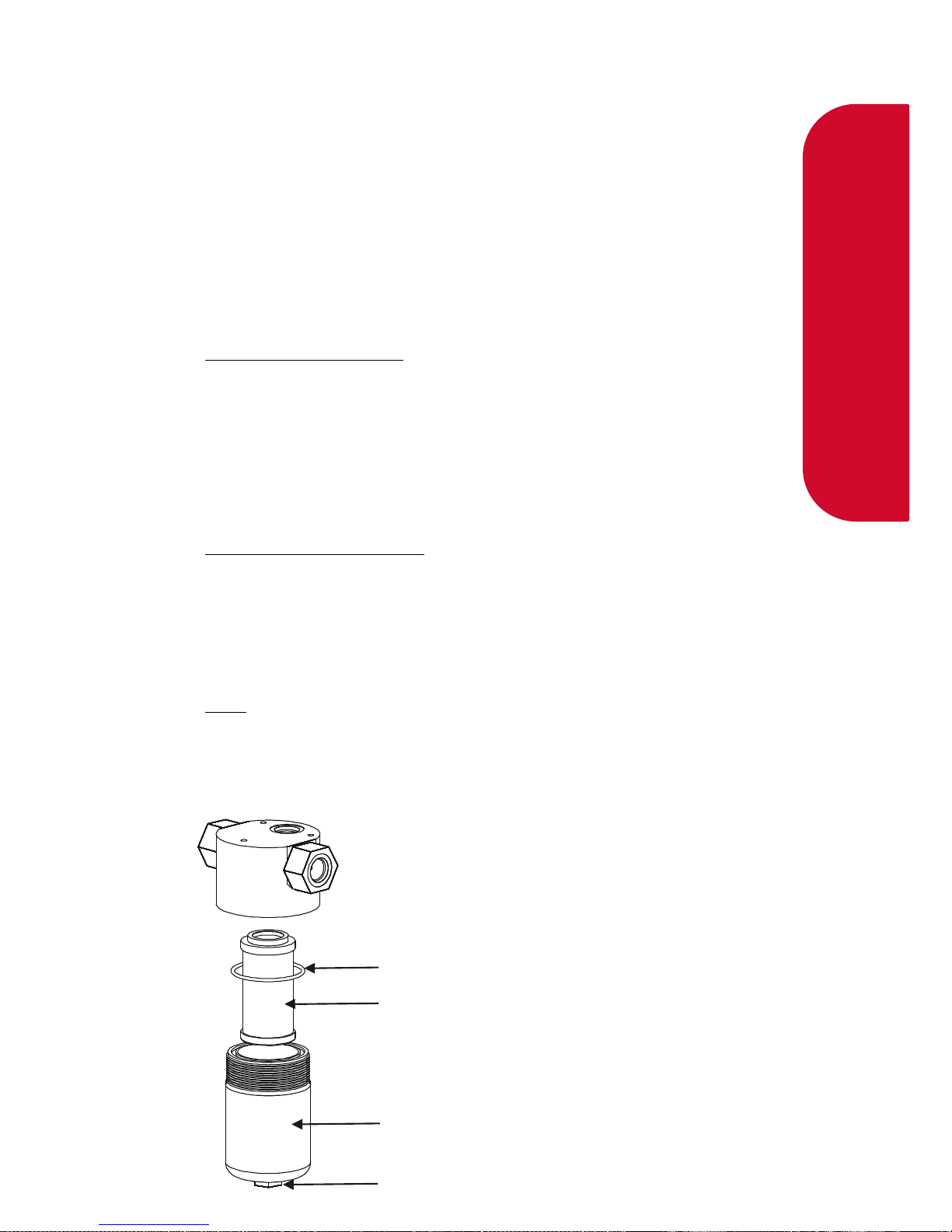
Filter Bowl O-ring Seal
Filter Element
Filter Bowl
Drain Plug
Filter Element Replacement
The coalescing filters are designed to trap dirt, moisture, oil, and other debris that
may damage the valve seals.
Before you start, make sure you have:
- A seal kit - Part number FC-FIL-0001
▪ 1 x filter
▪ 1 x filter bowl O-ring seal
- O-ring lubricant
Remove the coalescing filter
- Degas the dispenser.
- Drain the coalescing filters if they have not been drained already.
- Unscrew the filter bowl(s) with a spanner on the 22mm hex nut at the base of
the filter bowl.
- Remove the filter element.
- Clean all oil and dirt off the components with a clean cloth.
Install the new coalescing filter
- Insert the new filter element and lubricated filter bowl O-ring seal.
CAUTION: O-rings that are subjected to natural gas at high pressure swell when
exposed to air. Once swollen, they cannot be reused and must be replaced.
NOTE: Always use O-ring lubricant to prevent damage to the O-rings.
- Screw in the filter bowl(s)
- Check the dispenser for leaks.

39.
Servicing
Solenoid Valve Seal Replacement
These instructions refer to the current Compac S2-350 solenoid valve. The
solenoids are available in several types: Standard, high oil and low temperature.
Always quote the dispenser serial number when ordering parts and check the
model number on the valve body before installation.
NOTE: For applications where the gas has a high oil content, a special piston with
an O ring seal is available. If you are having problems, discuss this option with your
service agent. If the special piston is used for low oil content gas, no harm will
occur, but the service life of the seal may be shortened.
Before you start, make sure you have:
- A seal kit - Part number FC-SK-0001
▪ 1 x Teflon valve seal
▪ 1 x solenoid top O-ring seal
▪ 1 x gas return line O-ring seal
- O-ring lubricant
- Solenoid piston - Part number FC-VLV-PSTN-0001 (optional standard)
- Solenoid piston – Part number FC-VLV-PSTN-S2 (optional high oil)
- Solenoid top service kit standard. Part number FC-SVK-0003 (replace valve top
if leak detected through stem)
- Solenoid top service kit - low temperature option (-40 degrees C). Part number
FC-SVK-0004 (replace valve top if leak detected through stem).
CAUTION: Never remove or service the stem. If it is leaking, it must be replaced
using the appropriate top service kit.
CAUTION: Cleanliness is essential. When working on the open solenoid assembly,
cover the opening with a cloth to prevent dust and dirt from entering.
CAUTION: O-rings that are subjected to natural gas at high pressure swell when
exposed to air. Once swollen, they cannot be reused and must be replaced.
CAUTION: The Nitrile O-rings have a life span of over 10 years from cure date but
improper handling of these O-rings before use can shorten their useful life. O-rings
will deteriorate if exposed to ozone or ultraviolet light so keep in original packaging
and away from UV light. If in unsure about their condition, do not use old O-rings
and order new ones.
NOTE: It is not necessary to remove the solenoid body from the dispenser to service
the solenoid seals.

40.
Servicing
Remove the Old Solenoid Valve Seals
- De-gas the dispenser.
- Switch off the power supply to the dispenser.
DANGER: Never remove any electrical components without first switching off the
power to the dispenser. Failure to turn off the power could result in an electric
shock.
- Unscrew the solenoid coil retaining nut and move the coil out of the way.
- Remove the six cap screws from the solenoid top.
NOTE: Do not remove the angled grub screw from the solenoid top. This is epoxied
in place during manufacture and should never be removed.
- Remove the solenoid top and remove the old top O-ring seal and gas return O-
ring.
- Remove the solenoid spring.
- Screw an M6 cap screw into the solenoid piston to withdraw it from the
solenoid body.

41.
Servicing
- Taking care not to damage the piston, hold the flat part of the piston with a
spanner to prevent rotation, then unscrew the M6 x 12 mm cap screw from
the bottom of the piston. This releases the solenoid seal retainer and valve
seal.
- Discard the old valve seal.
- Clean all oil and dirt off the components with a clean cloth and check that
the bleed hole is not blocked.
- While the solenoid is apart, inspect the solenoid piston centre seal and piston
for wear, scratching or damage. Replace piston if required.
Install new Solenoid Valve Seals
- Place the new valve seal and seal retainer on the cap screw.
- Taking care not to damage the piston, hold the flat part of the piston to prevent
rotation, and then screw the M6 cap screw into the bottom of the piston.
- Insert a new gas return O-ring.
- Insert the piston back into the solenoid body.
- Insert the solenoid spring.
- Replace the solenoid top O-ring seal.
- Place the solenoid top back on the solenoid body, making sure that the locating
dowel is engaged.
- Screw in and tighten the six cap screws.
- Replace the solenoid coil.
- Re-power and re-gas the dispenser then check for leaks and correct operation of
the valve.

42.
Servicing
Solenoid Coil Replacement
Before you start, make sure you have:
- Replacement solenoid coil FC-COIL-0005 (Compac S2-350).
NOTE: Solenoid coils are not interchangable between models. Make sure you order
the correct one by quoting the dispenser serial number. To replace obsolete coils,
the entire solenoid will need replacing.
Remove the Solenoid Coil
- De-gas the dispenser.
- Switch off and isolate the power supply to the dispenser.
DANGER: Never remove any electrical components without first switching off the
power to the dispenser. Failure to turn off the power could result in an electric
shock.
- Remove the flameproof box lid to gain access to the C4000 power supply
board.
- Disconnect the appropriate solenoid coil wiring from the C4000 power supply
board.
CAUTION: Take basic anti-static precautions by wearing a wristband with an earth
strap.
- Loosen the gland on the flameproof box that is clamping the solenoid coil lead
and pull the lead out of the gland.
Undo the nut on the top of the solenoid valve that is securing the coil and remove
the coil from the top of the valve
Install the New Solenoid Coil
- To install a new solenoid coil, reverse the procedure above.
NOTE: Before replacing the lid on the flameproof box, make sure that the O-ring is
not damaged and is seated properly in its groove. If the O-ring is damaged and
needs replacing, replace it with an O-ring of the same size and specification (176
N70).

43.
Servicing
Complete Solenoid Valve Replacement
These instructions refer to the current Compac S2-350 solenoid valve. This
replaces all previous solenoids.
Before you start, make sure you have:
- Solenoid valve standard 350 bar model (FC-VALVE-0035) or
- Solenoid valve 350 bar O ring seal option for high oil content gasses (FC-
VALVE-0036) or
- Solenoid valve 350 bar low temperature option (FC-VALVE-0037)
NOTE: Solenoid valves are supplied without coils. If you need the coil it must be
ordered as well.
CAUTION: Cleanliness is essential. When working on the open pipes and
solenoids, cover the openings with a clean, lint-free cloth to prevent dust and dirt
from entering.
Remove the Old Solenoid Valve
- De-gas the dispenser.
- Switch off the power supply to the dispenser.
DANGER: Never remove any electrical components without first switching off the
power to the dispenser. Failure to turn off the power could result in an electric
shock.
- Undo the nut and remove the solenoid coil.
- Undo the gland nuts connecting the solenoid valve to the pipework and
manifold and remove valve
Replacing Solenoid Valve
- Ensuring all surfaces are clean and any sealing plugs are removed from
the valve, reconnect the pipework and tighten the gland nuts.
- Replace the solenoid coil.
- Repower and re-gas the unit, check for leaks and test for correct
operation.

44.
Servicing
Regulator Valve Seal Replacement
Before you start, make sure you have:
- A regulator seal kit - Part Number FC-SK-0002
▪ 2 x regulator O-ring seals
▪ 2 x Teflon back-up ring
▪ 1 x Teflon valve seal
- O-ring lubricant
Remove the Old Regulator Valve Seals
- De-gas the dispenser.
- Open the dispenser access doors.
- Unscrew the spring tube by placing a 1 ¼" spanner on the machine hex nut
at the top of the spring tube.
NOTE: Do not unscrew the valve adjustment nut. The spring remains at the set
tension.
- Unscrew the bottom plug in the regulator body.
- Using a hex key inserted into the base of the piston to stop the piston from
twisting sideways and being damaged, push the piston downwards out the
bottom of the regulator body.
- Hold the piston by the 8mm flat and remove the M6 cap screw from the
bottom.
NOTE: The M6 cap screw has a special hole through it. Never substitute it for a
normal cap screw.

45.
Servicing
Install New Regulator Valve Seals
- Install the new valve seal. Make sure that the larger flat side of the
seal faces upwards.
NOTE: O-rings that are subjected to natural gas at high pressure swell when
exposed to air. Once swollen, they cannot be reused and must be replaced.
CAUTION: The Nitrile O-rings have a life span of over 10 years from cure
date but improper handling of these O-rings before use can shorten their
useful life. O-rings will deteriorate if exposed to ozone or ultraviolet light so
keep in original packaging and away from UV light. If in unsure about their
condition, do not use old O-rings and order new ones.
- Lever off the two regulator O-rings and two Teflon back-up rings.
- Install two new regulator O-rings and two new Teflon back-up seals.
The back-up rings go on the outside of the O-rings.
NOTE: Always use O-ring lubricant on the O-rings to increase the service life.
- Reassemble the piston.
- Push the piston back up into the regulator body with a hex key.
NOTE: Keep the piston straight, rotate it clockwise to prevent the new O-ring
from catching or ripping.
- Screw in the bottom plug.
- Screw on the spring tube until tight.
Check the setting and sealing of the regulator for correct pressure.
A
B
DETAIL B
Regulator O-Ring
Teflon Back-Up Ring
DETAIL A
Teflon Back-Up Ring
Regulator O-Ring
Make sure that the
flat face of the seal
faces up

46.
Servicing
Isolation Valve Seal Replacement
NOTE: Please make sure you identify the valve before disassembling it to make
sure you have the correct seal kit available.
Complete valve is part number FC-Valve-0001
Before you start
Obtain the following replacement parts and equipment:
- FC-SK-0010 Parker Isolation Valve Seal Kit
- Refer to Spare Parts list for other items that you may need.
Remove the isolation valve seals.
CAUTION: Take care when disassembling the valve, as a lot of parts look
similar.
- De-pressurise the valve and remove it from the pipework.
- Remove the handle and panel nut to remove it from the cabinet.
- Disassemble the valve, as per the drawing below.
- Undo the packing nut and remove packing washers, packing and stem.
- Undo the end connectors and remove the seals, seat assembly and ball
Clean all components with a clean dry lint free rag.
CAUTION: O-rings that are subjected to Natural Gas at high pressure. Swell
when exposed to air. Once swollen they must be replaced.
- Blow compressed air (100 psi) through all ports to remove any impurities
that may damage the seals in operation.
CAUTION: Wear appropriate safety eye wear when using compressed air.

47.
Servicing
Replace the isolation valve seals
CAUTION: Take care to keep all parts clean while assembling.
- Apply a light coating of approved grease to the ball then replace the ball
and ball seat sub-assemblies, making sure the slot in the ball is at the
top.
- Making sure the retainer seal and end connector O ring are in place,
screw in the end connectors. Do not tighten yet.
- Locate the stem in the ball slot then replace the stem washers, stem
packing and packing nut.
- Open and close the valve a few times to seat the ball valve before
tightening the end connectors and packing nut.
- Reattach the valve to the cabinet and reconnect the pipework.
- Reapply gas to the valve and check for leaks.
48.
Servicing
Gas Operated Valve (option) Seal Replacement
CAUTION: Follow all safety precautions listed at the front of this manual.
Before doing any work on the valve, ensure that the power is off and the
system pressure is reduced to atmospheric levels. Ensure that the pressure is
removed from both the inlet and outlet ports of the valve and from the air
supply line.
Before you start
Obtain the following replacement parts and equipment:
- FC-SK-0029 Oasis Gas Operated Valve Seal Kit
Always quote model and serial number of your dispenser when ordering.
Diassembly
CAUTION: Take care when disassembling the valve, as a lot of parts look
similar.
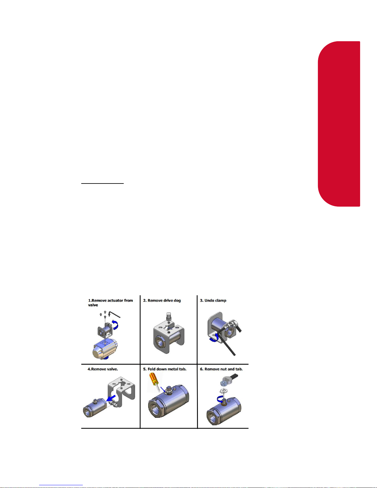
- Undo the pipework and remove the valve and actuator.
- Undo the four Allen screws and remove the actuator from the valve
- Remove the drive dog (note orientation)
- Undo clamp (note orientation of clamp in relation to flow direction)
- Remove valve from the clamp
- Fold down metal locking tab
- Remove nut and tab

49.
Servicing
- Use a pick to pull out the stem seal and discard.
- Undo the end cap, remove the valve seat and discard it.
- Turn the valve stem to the “Closed” position then tap on the end of the ball
valve with a wooden or soft plastic dowel (BV ASST) to remove it. Discard
the ball.
- Push the valve stem down into the valve and remove it from the valve
body. Discard the valve stem.
1. With a pick, carefully remove the second valve seat taking care not to
scratch the internal surfaces of the valve. Discard the valve seat.
2. Remove and discard the O-ring from the end cap.

50.
Servicing
Service kit
Suggested service tools
Replacement
- Thoroughly clean and dry the valve body and end cap.
- Place the new O-ring on the end cap and lubricate with the supplied
grease. Put an anti-seize compound on the threads.
- Fit the new valve seat making sure it is seated properly. Insert the valve
stem into the valve body and pull it upwards until it clicks into place.

51.
Servicing
- With the valve stem in the “Closed” position, insert the ball so the slot
engages with the stem.
- Insert the second valve seat
- Install the end cap and tighten to 60 N/m
- Install the valve stem gland then the lock tab and nut. Tighten nut to 3
N/m and bend the lock tab to stop the nut undoing
- Hold the valve stem with pliers and open and close the valve four or
more times to bed in the seal. Leave the valve in the closed position
- Reinstall the bracket, drive dog and air actuator
- Reinstall the assembled valve and connect pipework
- Repower the dispenser and check for correct operation of the valve and
for any leaks
DANGER: Do not use thread tape or sealing compounds on parallel SAE
fittings.
CAUTION: O-rings that are subjected to natural gas at high pressure swell
when exposed to air. Once swollen, they cannot be reused and must be
replaced.

52.
Servicing
Bleed Valve Replacement
The bleed valve seldom gives problems and is not serviceable
For a replacement valve and instructions if required, contact your Compac
service agent with your Model and Serial numbers
Pressure Relief Valve Replacement
The pressure relief valve seldom gives problems and is not serviceable
For a replacement valve and instructions if required, contact your Compac
service agent with your Model and Serial numbers
KG80 Meter Replacement
Removal
This section describes how to replace the KG80Meter.
- Shut off gas supply and degas the meter.
- Remove the inlet and outlet pipes from the old meter.
- Unscrew the SAE fittings from the meter inlet and outlet.
- Take note of the position and orientation of the communications plug
then unplug the meter cable from the C4000 processor board and cut
any cable ties that hold it in place.
- Undo the four bolts that hold the meter on the dispenser frame.
- Remove the old meter.
Replacement
- Secure the new meter to the dispenser frame using the four bolts.
- Plug the communications cable into the C4000 processor board.
- Screw the SAE fittings into the meter inlet and outlet.
- Install the inlet and outlet pipes.
- Cable tie the communications cable to avoid pulling or damage to it.
- Pressurise the meter and check for leaks.
- Calibrate the meter in accordance with the instructions in the
dispenser service manual.
53.
Servicing
Compac Breakaway Seal Replacement
This section describes how to replace the seal in a QBCI model breakaway.
The Compac Breakaway QBCI is only used on 15 kg/min models or on
models where the vent is returned to the dispenser.
The excess flow end (female) and check valve end (male) should not require
servicing. Both have metal to metal seats that are not affected by dirt.
Before you start, make sure you have:
Obtain the following replacement parts and ancillary equipment:
- A seal kit - Part number FC-SK-0011
▪ 3 x O-rings
▪ 2 x probe O-rings
- O-ring lubricant
Reassemble the Breakaway
In the event of a breakaway, check the O-rings in the male end of the
breakaway for damage.
If they are damaged, replace the breakaway QBCI seals by following the
steps below.

54.
Servicing
Replace the Breakaway Seals
To replace the breakaway seals:
- Remove the old O-rings.
NOTE:If you are dismantling the quick breakaway valve, make sure that you
have a spare seal kit available. O-rings that are subjected to natural gas at
high pressure swell when exposed to air and must be replaced.
- Replace the old O-rings with the new lubricated O-rings.
NOTE: Always use O-ring lubricant to prevent the O-rings from being
damaged.
If the breakaway parts under gas pressure for no apparent reason check that
the pressure relief hole is clear. If the pressure relief hole is blocked, gas
pressure will force the male and female ends apart.
Reconnect the Breakaway
To reconnect the breakaway:
- Make sure that both male and female receptacle breakaway parts are
clean before reassembly.
- Check that the pressure relief hole is clear.
NOTE: If the pressure relief hole is not clear, gas pressure will force the male
and female ends to part.
- Firmly connect the female and male connectors.
NOTE: If the breakaway is not connected correctly when gas pressure is
applied, it will come apart completely.

55.
Servicing
Three-Way Refuelling Valve Seal Replacement
NOTE: Make sure you identify the valve before disassembling it to make sure
you have the correct seal kit available. For more information see Compac
Technical bulletin CTB10015.
Before you start
Obtain the following replacement parts and equipment:
Seal Kit Part Number is FC-SK-0049
Three-way valve ball spindle is FC-SVK-0002 (optional)
Remove the three-way valve seals.
CAUTION: Take care when disassembling the valve, as a lot of parts look
similar.
- De-pressurise the valve and remove it from the hose assembly.
- Disassemble the valve, as per the figure on the next page.
Clean all components with a clean dry lint free rag.
CAUTION: O-rings that are subjected to Natural Gas at high pressure. Swell
when exposed to air. Once swollen they must be replaced.
- Blow compressed air (100 psi) through all ports to remove any impurities
that may damage the seals in operation.
CAUTION: Wear appropriate safety eye wear when using compressed air.
Install New Three-Way Valve Seals
- Cut the handle shaft back-up ring on an angle so it can be fitted onto the
shaft
NOTE: Check that the back-up rings are free of burrs and sharp edge.
- Position the seals in the appropriate slots on the handle shaft.
CAUTION: O-rings that are subjected to Natural Gas at high pressure swell
when exposed to air. Once swollen they must be replaced.

56.
Servicing
- Insert the handle shaft into the valve body from the bottom.
- Insert the ball shaft into the valve body from the bottom.
Note: Ensure that the slotted handle shaft and ball shaft engage.
- Insert the ball shaft seals in both sides of valve body.
- Insert the ball shaft retainers in either side of the valve body until the
retainer face meets with body of the valve.
- Place the handle on the handle shaft and screw in the grub screw to lock
it in place.
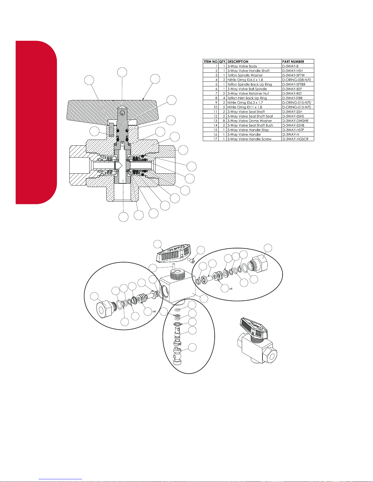
57.
Servicing
Compac Refuelling Valve Exploded View
16
17
15
2
1
4
5
3
6
12
11
13
8
14
7
10
9
11
12
13
14
8
9
8
10
7
15
16
17
12
11
14
8
8
7
10
9
13
1
5
4
4
3
2
6
Retainer Nut “B” assembly
Retainer Nut “A” assembly
Shaft/Spindle assembly

58.
Servicing
Refuelling Hose Replacement
Remove refuelling hose
- De-gas the dispenser.
- Undo the JIC hose connection at the dispenser's outlet block.
- Undo the connection between the hose and the nozzle assembly
Install new refuelling hose
- Attach the nozzle assembly to the new hose.
- Attach the new hose to the dispenser at the outlet block.
- Regas the dispenser and push the Start button to fill the new hose
assembly with gas.
- Check all hose connections for leaks by applying soapy water
mixture and looking for bubbles.
Power Supply Fuse Replacement
NOTE: There are three fuses used in the C4000 power supply, and each fuse
has a different rating.
Before you start, make sure you have:
The following fuses with these ratings:
▪ F1 = 0.5 A
▪ F2 = 0.25 A
▪ F3 = 1.0 A
▪ OR Compac fuse kit F-C4PWR-FUSEKIT
Fuse locations are displayed on the C4000 Power Supply Board
.
NOTE: Every new dispenser is supplied with one spare fuse of each value
located on the inside of the flameproof box lid.

59.
Servicing
Remove C4000 power supply fuse(s):
- Degas the dispenser.
- Switch off the power supply to the dispenser.
DANGER: Never remove any electrical components without first switching off
the power to the dispenser. Failure to turn off the power could result in an
electric shock.
- Remove the flameproof box lid.
- F2 is underneath the top PCB, and the board must be removed to access
the fuse.
- Remove the blown fuse and discard.
CAUTION: Take basic anti-static precautions by wearing a wristband with an
earth strap.
Install new C4000 power supply fuse(s):
- Replace the blown fuse element with a new one of equal type and rating.
CAUTION: You must use the correct rating when replacing a fuse. The
correct ratings are printed next to each fuse on the printed circuit board.
Using the incorrect fuse rating may compromise the intrinsic safety of the
dispenser.
- Replace the flameproof box lid, ensuring that the O-ring in the lid
engages in its associated groove.
- Turn on the power to the dispenser.
DANGER: Do not power up the dispenser with the flameproof box lid
removed.
NOTE: Before replacing the lid on the flameproof box, make sure that the Oring is not damaged and is seated properly in its groove. If the O-ring is
damaged and needs replacing, replace it with an O-ring of the same size and
specification (176 N70).

60.
Servicing
Power Supply Replacement
Before you start
Obtain the following replacement parts
- Replacement Power Supply part number F-CP-C4PWR-ASSEM
Remove the C4000 Power Supply
- De-gas the dispenser.
- Switch off the power supply to the dispenser.
DANGER: Never remove any electrical components without first switching off
the power to the dispenser. Failure to turn off the power could result in an
electric shock.
- Remove the flameproof box lid to gain access to the C4000 power supply
board.
CAUTION: Take basic anti-static precautions by wearing a wristband with an
earth strap.
- Disconnect the incoming power wiring from the phase and neutral
terminals, and from the earth bar.
- Remove all of the solenoid and communications plugs on the top of the
C4000 power supply board, with the wiring still intact.
- Remove the screws that are securing the earth bar, taking care not to
lose any of the spacers or other mounting hardware.
- Remove the two screws on the other end of the C4000 power supply
board.
- Carefully slide out the C4000 power supply board to gain access to the
plugs on the IS Cable that connect into the bottom PCB, and unplug
these.
Completely remove the C4000 power supply board.

61.
Servicing
Install the New C4000 Power Supply
- To install the new C4000 power supply, reverse the procedure above
CAUTION: Make sure that the triac snub switches SW1, SW2, & SW4 are left
in the factory set position 2 (Low Current Output) after you have completed
all procedures. Switches are easily knocked out of position during service.
The C4000 Power Supply Board section shows the appropriate switch
settings used on the dispenser.
DANGER: Before replacing the lid on the flameproof box, make sure that the
O-ring is not damaged, and is seated properly in its groove. If the O-ring is
damaged and needs replacing, replace it with an O-ring of the same size and
specification (176 N70).
NOTE: It should not be necessary to recalibrate the dispenser. However, in
some locations, this may be legally required as per the Calibrate the Meter
section.
Processor Board Replacement
Before you start
Obtain the following replacement parts
- Replacement C4000 Processor part number F-CP-C4PROCES-A
Remove the C4000 Processor board
- De-gas the dispenser.
- Remove the cover of the C4000 enclosure.
- If possible, record all the set-up data by accessing the Parameter switch
(SW1) and the K-Factor switch (SW2). The Software Set-Up and Upgrade
section contains details on obtaining this information.
- Switch off the power supply to the dispenser.
- Remove both the EPROM and memory chips Dispenser Software
Upgrade/Replacement.
CAUTION: Take basic anti-static precautions by wearing a wristband with an
earth strap.
- Unplug all wiring from the C4000 microprocessor board and remove the
board from its position.
CAUTION: Take basic anti-static precautions by wearing a wristband with an
earth strap.

62.
Servicing
Install New C4000 Processor
- Put the new board in place of the old one, and plug all the wiring back in
the same order as before.
- Refit the EPROM and memory chips, as per Dispenser Software
Upgrade/Replacement
- Check dispenser operation Checking Dispenser Operation
NOTE: It should not be necessary to recalibrate the dispenser.
Temperature Pressure Board Replacement (Fast Fill & Temperature
compensation Units Only)
Before you start
Obtain the following replacement parts
- Replacement Temperature and Pressure board part number :
F-CP-CNG-TEMP
Remove the Temperature pressure board
- De-gas the dispenser.
- Switch off the power supply to the dispenser.
DANGER: Never remove any electrical components without first switching off
the power to the dispenser. Failure to turn off the power could result in an
electric shock.
- Access the temperature pressure board.
CAUTION: Take basic anti-static precautions by wearing a wristband with an
earth strap.
Unplug all wiring from the temperature pressure board and remove the board
from its position.
Install New Temperature pressure board
- Put the new board in place of the old one, and plug all the wiring back in
the same order as before.
- Turn the power to the dispenser back on.
- Check Dispenser operation. Checking Dispenser Operation.
NOTE: It should not be necessary to re-calibrate the dispenser unless a
pressure transducer or temperature probe needs to be replaced.

63.
Servicing
Dispenser Software Upgrade/Replacement
You can only upgrade the dispenser software by replacing the EPROM chip.
Follow this software upgrade procedure for all CNG Dispensers that use the
C4000 Microprocessor.
CAUTION: Before working on the dispenser electronics, take basic anti-
static precautions by wearing a wristband with an earth strap.
Record Set-up Data and Tote Information
- Access the C4000 Microprocessor PCB by opening the front panel.
- Record all the set-up data by accessing the Parameter switch (SW1)
and the K-Factor switch (SW2). Refer to Parameter Switch Settings and
K-Factor Switch Settings to obtain this information.
The following data is required from the Parameter switch (SW1):
▪ Dispenser pump price.
▪ Dispenser pump number.
▪ Dispenser sequencing rate.
▪ Software Program number, if you are upgrading to a new version.
The following data is required from the K-Factor switch (SW2):
▪ The K-Factor. There is a value for side A and side B in dual hose
dispensers.
▪ The temperature.
▪ The Set Resolution. This sets the number of decimal places after
the decimal point.
▪ The pressure values. ( Record if applicable: u uA uA2 ub
ub2 )
▪ The pressure gain. (Record if applicable: GAin GAinA
9Ainb GAinA2 GAinb2)
▪ Configuration Code C.
▪ Configuration Code b.
▪ The Density Factor.
- Record the tote information by pressing the nozzle switch or start
button quickly five times

64.
Servicing
Remove the software EPROM
- Turn off the dispenser.
- Remove the software EPROM chip, using an EPROM extractor
Install new software EPROM
- Plug in the new software EPROM, checking that all of the legs are
correctly located in the socket. The chip should be located as far to
the bottom of the socket as possible. This leaves a gap of two pins
from the top of the chip to the top of the socket. Pin 1 of the
EPROM is then located in the top left corner (pin 3 of the socket).
- Turn on the dispenser.
- Check that the initial set-up data and tote information is the same.
- If the initial set-up data is different, re-enter this information, as per
Parameter Switch Settings and K-Factor Switch Settings.
- Check the dispenser operation Checking Dispenser Operation.

65.
Servicing
Meter Replacement
Before you start, make sure you have:
- A new Compac meter F-D-METER-KG80T
Remove the Meter
- De-gas the dispenser.
- Remove the tubing from the meter inlet and outlet.
- Unscrew the SAE fittings from the meter inlet and outlet.
- Unplug the meter connections to the C4000 processor.
- Undo the four bolts that hold the meter on the dispenser frame.
- Remove the meter.
Install new Meter
- Reverse the steps above to install the new meter.
- Enter the new meter K-Factor into the C4000 processor Meter K
Factor.
- Check the dispenser calibration with the master meter. Refer:
Meter Calibration.
Unserviceable Parts List
The following parts are unserviceable on site and have to be returned to
Compac for servicing.
Part
Comment
KG meter
The KG meter:
- Can have its firmware upgraded by approved
service agents.
- Can only be serviced by Compac.
- Has no set-up functions.
- Is self-characterising. The only function performed
in the set-up is setting the K- Factor on the C4000
head.
C4000 power supply
C4000 CPU Board
Nozzles
Solenoid stem
Replacing the solenoid stem seal requires special tooling.

66.
Dispenser Calibration
Dispenser Calibration
Meter Calibration
Calibrating the meter involves:
▪ Comparing the dispensers stated amount dispensed to actual
amount dispensed.
▪ Adjusting the K-Factor if accuracy is not within the required
tolerance.
NOTE: The K-Factor for each new dispenser is factory set and usually does
not need to be changed.
Test the meter accuracy
Record the dispenser’s current density factor and set it to read out in kg
Density Factor (dSF).
• Test the meter accuracy using Calibration Test Fill Procedure - Method
1 or Calibration Test Fill Procedure - Method 2.
Calculate the meter K-Factor
- Make sure that the dispenser is idle, with the nozzle in its holster.
- Press and release the K-Factor switch nine times.
- The display shows the K-Factor as F ***** (single nozzle
dispenser) or FA ***** (Side A of a dual nozzle dispenser).
- To view the K-Factor for side B, quickly press and release the K-
Factor switch eight more times when viewing side A. The display
shows Fb ***** (side B of a dual nozzle dispenser).
NOTE: With a dual dispenser, it’s easier to set side A first.
Calculate the new K-Factor with the following formula:

67.
Dispenser Calibration
Input dispenser settings
- Input the new meter K-factor (FA & Fb).
- Set the density factor back to its original value. (dSF).
Calibration Test Fill Procedure (Method 1)
Method 1 of checking calibration involves filling a gas bottle and comparing
the read-out scale reading with the dispenser display reading.
Before you start, make sure you have:
- Certified weighing scales with a read-out accuracy of +/- 20 g or
better and a range of 0—120 kg
- A CNG cylinder with a fill and release valve
To carry out the calibration test fill procedure (Method 1):
- Put the CNG cylinder on the scales.
- Empty the CNG cylinder by venting it to the atmosphere.
DANGER: Always vent cylinders in a safe manner and safe location.
- Zero the TARE read-out on the scales.
- Fill the CNG cylinder from the dispenser.
- Compare the read-out weight (True Quantity) on the scales with the
dispenser display (Display Amount).
If the results are not within 0.5% of each other, you will need to change the
calibration, as per the Calculate and Set the New K-Factor section.
Calibration Test Fill Procedure (Method 2)
Method 2 of checking calibration involves filling a vessel and comparing a
master meter reading with the dispenser display readings.
This method assumes that the master meter is sufficiently accurate and
reliable enough to be considered a good reference.
Before you start, make sure you have:
A master meters
To carry out the calibration test fill procedure (Method 2):
- Plug the dispenser refuelling probe into the master meter, and then
plug the master meter refuelling probe into a vehicle to fill.
- Turn on the master meter valve, if applicable, and reset to zero.

68.
Dispenser Calibration
- Fill the vehicle from the dispenser.
- Turn off the dispenser refuelling valve and master meter valve, if
applicable.
- Compare the master meter read-out (True Quantity) with the dispenser
display (Display Amount).
If the results are not within 0.5% of each other, you will need to change the
calibration, as per the Calculate and Set the New K-Factor section
Pressure Transducer Calibration (Fast Fill & Temperature Compensated
Units Only)
Calibrating the dispenser pressure transducers involves two steps:
- Determine the transducer gain. Compare the dispensers gauge
pressure to its electronic pressure reading to determine and set the
correct transducer gain.
- Adjust the transducer gain by adjusting the dispenser’s electronic
pressure reading to match the actual pressure.
NOTE: The pressure transducers are calibrated at the factory and usually do
not require recalibration.
Determine transducer gain
- Degas the dispenser and close all outlet isolation valves
- View and note down the current transducer gain (TG) setting for the
transducer to be tested. Pressure Transducer Gain.
- Turn on the gas to the dispenser.
- Remove the nozzle from its holster or press the start button, allowing
gas to pass through the dispenser.
- Slowly open the outlet isolation valve and watch as the pressure gauge
begins to rise. Shut the valve when the reading is approximately 100
bar.
- Hang up the nozzle.
- View and record the electronic pressure reading for the pressure
transducer. This value is D1.
- Record the value on the dispenser gauge. This value is TG1.
- Remove the nozzle from its holster again or press the start button.
- Increase the gauge pressure to approximately 200 bar.
- Hang up the nozzle.
- View and record the electronic pressure reading for the pressure
transducer. This value is D2.
- Record the value on the dispenser gauge. This value is TG2
- Calculate the new gain using the following formula:

69.
Dispenser Calibration
Adjust the transducer gain
Input the new gain. Refer Pressure Transducer Gain.
Adjust the electronic pressure offset
Adjust the electronic pressure reading to equal that displayed on the
dispenser’s pressure gauge using the following procedure:
- Use the "K" factor switch to display the pressure reading.
- Press and hold the "K" factor switch to change the display to equal
the pressure on the gauge.
- Allow the "K" factor setting to time out.
- Re-check the pressure at 100 and 200 bar gauge pressure to see if
display and gauge read the same.
Ambient Temperature Sensor Calibration
Calibrating the Ambient Temperature Sensor involves:
- Comparing the dispensers stated temperature to the actual
temperature.
- Adjusting the ambient temperature reading if it is found to be
incorrect.
Test the sensor accuracy
Using a calibrated temperature meter, determine the temperature of the
body of the dispenser Ambient temperature sensor.
Access the current dispenser ambient temperature reading.
Adjust dispenser reading
Adjust the dispenser’s ambient temperature reading to match that of the
calibrated temperature meter.

70.
Appendix
Appendix
The C4000 electronic head is ATEX approved for use in a Class 1, Zone 1 hazardous
area. Dispensers are wired to Class 1, Zone 1 Australian and European standards.
Approval numbers appear on labels attached to the C4000 lid and the flameproof
junction box lid.
ATEX Approval Marking
on the Equipment
Equipment or Protective
System
EC - Type Examination
Certificate Number
2 G EEx d A T3 (T
amb
= -25°C to + 55°C)
A Type C4000 Control Unit
Baseefa03ATEX0612
(2)G [EEx ib] A
(-25°C ≤ Ta ≤ 80°C)
C4000 Power Supply Unit
PCB CI138 & CI139
Baseefa03ATEX0684X
G EEx ib A T3 (-
25°C ≤ Ta ≤ 80°C)
(CWIT Aerial only:-
1G EEx ia A T3
C4000 Fuel Dispenser
Control Unit
Baseefa03ATEX0683X
The Compac CNG equipment is also PED approved for use up to 275 bar.
PED Approval Marking
on the Equipment
Equipment
EC - Type Examination
Certificate Number
Cat. II Group I
Filter housing, Solenoid, &
various Dispenser models.
SGS UK Ltd. 0790/025074

71.
Specifications
Specifications
Model Specifications
There are various CNG Dispenser models and options available.
The models include:
▪ Legend frame or Laser frame.
The options include:
▪ One, two or three lines.
▪ Single or dual hose.
▪ Fixed pressure final cut-off or temperature compensated final fill cut-off.
▪ Standard, high or ultra-high flow.
Model
Numbers
Standard
High Flow
Ultra-High Flow
Laser
Single
L-CNG15
L-CNG50
L-CNG50-15
L-CNG80
L-CNG80-15
Dual
L-CNGD15
L-CNGD50
L-CNGD80
Legend
Single
LGDCNG15
LGDCNG50
LGDCNG50-15
LGDCNG80
LGDCNG80-15
Dual
LGDCNGD15
LGDCNGD50
LGDCNGD80
LE3KG25D
(Pakistan only)

72.
Specifications
Technical Specifications
Operating Conditions:
Compac CNG Dispensers (excluding hose assembly) are designed to operate within the
atmospheric environment. Gas parameters are outlined below.
CNG Dispensers require the following operating conditions:
CNG Dispensers require the following operating conditions:
Air temperature range
- 25 °C to + 55 °C
Air humidity range
10% to 95%
Gas type
High pressure natural gas
(CNG)
Gas temperature
- 40 °C to + 80 °C
(continuous)
- 55 °C to + 80 °C
(intermittent)
Maximum water Dew Point
- 32 °C at 250bar
Maximum Working Pressure(Inlet)
275bar (350 bar option)
General
Specifications
Power Requirements
230V +/-10%, 50Hz, 2A

73.
Specifications
Specific
Specifications
Standard Model
High-Flow Model
Ultra-High-Flow
Model
Flow
(The maximum flow
rate is not only
determined by the
type of dispenser but
also depends on the
size of the refuelling
hose, the model of
the breakaway, the
type of refuelling
nozzle, and the
vehicle coupling.)
1 – 15 kg /min
1-50 kg /min
1 – 80 kg /min
Pressure rating
(350 bar options
utilise air actuated
valves and require a
compressed air
supply.)
275 bar
(350 bar option)
275 bar
(350 bar option)
350 bar
Accuracy
+/- 1.0%
+/- 1.0%
+/- 1.0%
Meter
Compac KG80
coriolis mass flow
Compac KG80
coriolis mass flow
Compac KG80
coriolis mass flow
Internal Pipework
1/2”
1/2”
1/2” or 3/4"
Refuelling hose
3/8”
1/2”
1/2” or 3/4"
In-line breakways
Various available
Various available
Heavy duty
Refuelling valve
NGV1 or NZ 7/16"
probe
NGV1 or NGV2
NGV2
Laser (without
hoses or high
masts)
830W x 450D x
1608H
830W x 450D x
1608H
830W x 450D x
1608H
Legend (without
hoses)
850W x 425D x
2355H
850W x 425D x
2355H
850W x 425D x
2355H
Minimum flow cut
off
0.5 -10 kg/min
(settable)
0.5 -10 kg/min
(settable)
0.5 -10 kg/min
(settable)
Maximum flow cut
off
10 - 99 kg/min
(settable)
10 - 99 kg/min
(settable)
10 - 99 kg/min
(settable)

74.
Specifications
Component Specifications
See below for information on serviced equipment.
Equipment
Item
Compac Code
Specifications
Description
Coalescing
filters
Grade 10
Coalescing Filter
The coalescing filters are
designed to trap dirt, moisture,
oil, and other debris that may
damage the valve seals. A Grade
10 coalescing filter will remove
95% of liquid aerosols in the 0.3
to 0.6 micron range.
Compac
filter/check
valve
FCVCI-12-SS
3/4” SAE female
inlet.
2 x 3/4” SAE
female outlets.
350 bar max.
The filter/check valve prevents
back-flow from the high storage
to the medium and low storage,
and from the medium storage to
the low storage.
The valve has a metal to metal
seat and should not leak or
require servicing.
Solenoid
valve
SCI-12-SS
3/4” SAE female
inlet.
3/4" SAE female
outlet.
275 bar max.
The high flow solenoid valve is
designed to control the flow of
gas in a CNG Dispenser.
Between the inlet and outlet, the
valve opens with a differential
pressure of more than 275 bar.
Regulator
valve
RCI-12-SS
3 x 3/4" SAE
female inlets.
3/4" SAE female
outlet.
275 bar max.
The regulator is a high flow valve,
designed to limit the outlet
pressure of the dispenser.
In the fixed pressure dispenser,
the regulator limits the final fill
pressure to 200 bar.
In the temperature
compensating dispenser, the
regulator acts as a safety device
to limit the amount of overpressure if the main solenoid fails
to shut off at the correct pressure.
Three-way
refuelling
valve
RVCI-04
1/4" NPT ports
250 bar max.
The three-way valve is designed
specifically for refuelling CNG
vehicles. The inlet, outlet, and
exhaust ports are designed to be

75.
Specifications
Equipment
Item
Compac Code
Specifications
Description
used as shown in the figure in the
Dispenser Component Location
section. Do not re-pipe the valve
in a different configuration.
Nozzles
7/16" NZ
Probe
1-15 kg/min
1/4" NPT port.
In New Zealand, the probe
complies with NZS 5425.1.
In Australia, the probe complies
with AS/NZS 2739.
OPW CT1000
1-50 kg/min
9/16" SAE inlet
port
200 bar max.
Nozzles allow refuelling for high
pressure NGV applications.
OPW CT5000
1-80 kg/min
7/8" SAE inlet
port
250 bar max.
Nozzles allow refuelling for high
pressure NGV applications.
Inline
breakaways
QBCI-09
1-15 kg/min
9/16" SAE inlet
& outlet ports
Brass inline breakaway with
reconnectable design.
OPW ILB- 1
1-50 kg/min
9/16" SAE inlet
& outlet ports.
250 bar max.
150 to 200 lbs.
(668 to 890 N)
breakaway
force.
Inline breakaway with
reconnectable design. CorrosionResistant with high flow for all
NGV-1 nozzles.
OPW ILB-5
1-80 kg/min
7/8" SAE inlet &
outlet ports.
310 bar max.
150 to 200 lbs.
(668 to 890 N)
breakaway
force.
Inline breakaway with
reconnectable design. CorrosionResistant with high flow quick
fuelling of large storage vehicles.
Isolation
ball valve
Parker 2-way 8 series ball valve
Microproces
sor
C4000
The Compac C4000 processor
controls all the electronics in the
dispenser.
Display
GD1, GD2 or
GD3
The display has six 1" digits for
price, six 1" digits for quantity
and four 3/4" digits for unit price.
(Available with one, two or three

76.
Specifications
Equipment
Item
Compac Code
Specifications
Description
unit price displays.)
Pressure
Gauge
Dual scale pressure gauges are
available with psi and either bar,
MPa, or kPa. CE Approved
Hose
Parker single
and twin line
hose.
3/8", 1/2" or
3/4".
The hose is specifically designed
to dissipate static electrical buildup and wear resistance. Each
hose assembly must be properly
grounded.
The temperature range for the
hose is -40 to +66°C.

77.
Mechanical Drawings
Mechanical Drawings
Dispenser Component Locator
NOTE: The C4000 Dispenser Power supply is housed in a flameproof box. All other
components are simply located in enclosures. See below.

78.
Mechanical Drawings
GA
MB
Inlet
Outlet
BV
Manifold Block Assembly
MBA
FV Filter Check Valve
SV Solenoid Valve.
RV Regulator Valve
KG KG80 Mass Flow Meter
IV Isolation Valve
GA
MB Manifold Block
GA Pressure Gauge
TR Pressure Transducer
PR Pressure Relief Valve
BV Bleed Valve
TR
(Temperature compensated models only)
OB Outlet Block
HB Hose from Outlet to Breakaway
BA Inline hose breakaway coupling
HN Hose from Breakaway to Nozzle
RA Refueling Nozzle Assembly
IN1
RV1KG1
KG2
SV5
SV6
SV1
SV2
SV3
SV4RV2
IV2
FV2
FV1
FV3
Low Bank Inlet
SIDE A SIDE B
OB2
MBA
IN2
Medium Bank Inlet
IN3
High Bank Inlet
BA2
RA2
HB2
HN2
IV1
OB1
MBA
BA1
RA1
HB1
HN1
(Two and Three Line Models)
(Optional)
(Three Line Models Only)
(See Below)
(Dual Hose Models Only)

79.
Mechanical Drawings
 Loading...