

Page 1

DCA Installation & Service Manual
Version 1.1.4
Page 2

Compac Industries Ltd.
Page 2
www.compac.co.nz
Conditions of Use
Read this manual completely before working on or
making adjustments to the Compac equipment.
Compac Industries Limited accepts no liability for
personal injury or property damage resulting from
working on or adjusting this unit incorrectly or
without authorisation.
Along with any warnings, instructions, and
procedures in this manual, you should also observe
any other common sense procedures that are
generally applicable to equipment of this type.
Failure to comply with any warnings, instructions,
procedures, or any other common sense procedures
may result in injury, equipment damage, property
damage, or poor performance of the Compac
equipment
The major hazard involved with installing and
operating the unit is electrical shock. This hazard
can be avoided if you adhere to the procedures in
this manual and exercise all due care.
Compac Industries Limited accepts no liability for
direct, indirect, incidental, special, or consequential
damages resulting from failure to follow any
warnings, instructions, and procedures in this
manual, or any other common sense procedures
generally applicable to equipment of this type. The
foregoing limitation extends to damages to person or
property caused by the unit or damages resulting
from the inability to use the unit including loss of
profits, loss of products, loss of power supply, the
cost of arranging an alternative power supply, and
loss of time, whether incurred by the user or their
employees, the installer, the commissioner, a
service technician, or any third party.
Compac Industries Limited reserves the right to
change the specifications of its products or the
information in this manual without necessarily
notifying its users.
Variations in installation and operating conditions
may affect the unit's performance. Compac
Industries Limited has no control over each
installation's unique operating environment. Hence,
Compac Industries Limited makes no
representations or warranties concerning the
performance of the unit under the actual operating
conditions prevailing at the installation. A technical
expert of your choosing should validate all operating
parameters for each application.
Compac Industries Limited has made every effort
to explain all servicing procedures, warnings, and
safety precautions as clearly and completely as
possible. However, due to the range of operating
environments, it is not possible to anticipate every
issue that may arise. This manual is intended to
provide general guidance. For specific guidance
and technical support, contact your authorised
Compac supplier, using the contact details in the
Product Identification section
Only parts supplied by or approved by Compac
may be used and no unauthorised modifications to
the hardware of software may be made. The use of
non-approved parts or modifications will void all
warranties and approvals. The use of nonapproved parts or modifications may also constitute
a safety hazard.
Information in this manual shall not be deemed a
warranty, representation, or guarantee. For
warranty provisions applicable to this unit, please
refer to the warranty provided by the supplier.
Unless otherwise noted, references to brand
names, product names, or trademarks constitute
the intellectual property of the owner thereof.
Subject to your right to use the unit, Compac does
not convey any right, title, or interest in its
intellectual property, including and without
limitation, its patents, copyrights, and know-how.
Every effort has been made to ensure the accuracy
of this document. However, it may contain technical
inaccuracies or typographical errors. Compac
Industries Limited assumes no responsibility for
and disclaims all liability of such inaccuracies,
errors or omissions in this publication.
Page 3

iii
Contents
Conditions of Use ............................................................................................................................................................. 2
Product Identification ....................................................................................................................................................... 6
Document Control Information ........................................................................................................................................ 7
Symbols and Units of Measure ........................................................................................................................................ 8
Safety ................................................................................................................................................................................. 9
Introduction ..................................................................................................................................................................... 10
Options................................................................................................................................................................... 11
Components ........................................................................................................................................................... 12
Litres Total ............................................................................................................................................................. 14
Installation Guidelines .................................................................................................................................................... 15
Electrical Connections.................................................................................................................................................... 17
Tank Gauging Setup .............................................................................................................................................. 18
Precautions when using Generator Power ................................................................................................................... 18
Wiring Diagram ................................................................................................................................................................ 19
Modem Connections ....................................................................................................................................................... 20
Operating Instructions .................................................................................................................................................... 22
CWID Key & CWID Block Readers ........................................................................................................................ 22
HID Readers .......................................................................................................................................................... 24
iTrack Reader ........................................................................................................................................................ 25
USB Module ..................................................................................................................................................................... 26
USB Memory Stick ................................................................................................................................................. 27
Uploading and Downloading Files ................................................................................................................................. 28
1) Do All ................................................................................................................................................................. 29
2) Set Price ............................................................................................................................................................ 30
3) Send Cards ........................................................................................................................................................ 30
4) Get Buffer .......................................................................................................................................................... 31
5) Get Transactions ............................................................................................................................................... 31
Working with USB Module Files .................................................................................................................................... 32
1) Cards ................................................................................................................................................................. 33
2) Price................................................................................................................................................................... 35
3) Transactions ...................................................................................................................................................... 36
Customising Your Transaction Reports ................................................................................................................. 37
Powering Up .................................................................................................................................................................... 39
Set Up ............................................................................................................................................................................... 40
System Setup ......................................................................................................................................................... 40
Page 4

Compac Industries Ltd.
Page iv
www.compac.co.nz
Main Menu Options ......................................................................................................................................................... 41
Option #1 REPORTS ............................................................................................................................................. 41
Option #2 CARDS .................................................................................................................................................. 42
Option #3 FUELS ................................................................................................................................................... 43
Option #4 SYSTEM ................................................................................................................................................ 45
Option #5 PUMPS .................................................................................................................................................. 54
Comms Options ..................................................................................................................................................... 57
Option #6 TANKS .................................................................................................................................................. 63
Option #7 PRODUCT GROUPS and GRADES ..................................................................................................... 67
Tanks/Pumps/Groups ............................................................................................................................................ 68
Setting Product Groups .......................................................................................................................................... 70
Assigning Pump Numbers to Hoses ............................................................................................................................. 71
Pump numbers for each model .............................................................................................................................. 71
Order of pump numbers ......................................................................................................................................... 71
Assigning Hoses to Product Groups............................................................................................................................. 71
Legend 4 Hose, 6 Hose and Laser 4 Hose Quad .................................................................................................. 72
Master, Premier and Laser (Single and Dual) ........................................................................................................ 73
Cards ................................................................................................................................................................................ 74
Expiry Date ............................................................................................................................................................ 74
Setting ISO and Access codes ............................................................................................................................... 74
Oil company ISO and Access codes ...................................................................................................................... 75
ATG / CE Box ................................................................................................................................................................... 76
Mechanical Registers ............................................................................................................................................. 77
Cardreaders ..................................................................................................................................................................... 81
Modems ............................................................................................................................................................................ 82
Dynalink (Hayes type) ............................................................................................................................................ 82
GSM Modem (Wavecom)....................................................................................................................................... 82
Lantronix .......................................................................................................................................................................... 83
Diagnostic LEDs .............................................................................................................................................................. 87
Diagnostic LEDs in a system with Compac comms only ....................................................................................... 88
Reports ............................................................................................................................................................................. 89
Deleting Transactions ............................................................................................................................................ 90
Troubleshooting .............................................................................................................................................................. 91
Error Messages ............................................................................................................................................................... 91
Service and Upgrade Procedures .................................................................................................................................. 92
Com FMS Board Replacement (DCA) ................................................................................................................... 92
C4000 Board Replacement .................................................................................................................................... 95
Compac Box Replacement .................................................................................................................................... 96
Fit PC Replacement ............................................................................................................................................... 97
Wiring a USB Module ............................................................................................................................................. 98
CWID Interface Board Replacement .................................................................................................................... 101
CWID Aerial Replacement ................................................................................................................................... 103
CWID Nozzle Aerial Replacement ....................................................................................................................... 104
HID Reader Replacement .................................................................................................................................... 106
iTrack Reader Installation and Replacement ....................................................................................................... 108
Card Reader Replacement .................................................................................................................................. 111
Multiplex Board Replacement .............................................................................................................................. 114
Keypad and Display Screen Replacement ........................................................................................................... 115
Router / Switch Replacement ............................................................................................................................... 116
Replacing the Receipt Printer .............................................................................................................................. 117
Page 5

v
Software Upgrading ............................................................................................................................................. 118
Maintenance .................................................................................................................................................................. 120
Receipt Printer ..................................................................................................................................................... 120
Replacing Paper - Seiko Printer ........................................................................................................................... 121
Changing Paper on a Custom Printer .................................................................................................................. 122
Appendix ........................................................................................................................................................................ 123
Comm FMS Board Connections .......................................................................................................................... 123
Plugs and Connectors .......................................................................................................................................... 126
Part Locations ............................................................................................................................................................... 130
Spare Parts List ............................................................................................................................................................. 132
DCA Cabinet ........................................................................................................................................................ 132
Electronic Components ........................................................................................................................................ 133
Modem / Router Options (DCA) ........................................................................................................................... 134
Printer .................................................................................................................................................................. 135
Card Reader ........................................................................................................................................................ 135
CWID HID & USB ................................................................................................................................................ 136
Exchange Parts .................................................................................................................................................... 136
Glossary of Terms ......................................................................................................................................................... 137
Installation Checklist .................................................................................................................................................... 138
Page 6
Product Identification
Compac Industries Ltd.
Page 6
www.compac.co.nz
Product Identification
Manual Title
DCA Installation and Service Manual
Publication Date
Wednesday, 29 August 2012
Application
Compac models RAS, DCA, CC DCA and variants
Power supply
220 - 240 V +/- 10%, 50 Hz, 1 Amp
Related Manuals
C4000 Master Manual (CWID and Mechanical Register DCAs)
CompacOnline User Guide (CompacOnline capable DCAs)
Validity
Compac Industries Limited reserves the right to revise or change
product specifications at any time. This publication describes the state
of the DCA at the time of publication and may not reflect the product at
all times in the past or in the future.
Manufacturer Contact
Details
The Compac DCA is designed and manufactured by:
Compac Industries Limited
52 Walls Road, Penrose, Auckland 1061, New Zealand
P.O. Box 12-417, Penrose, Auckland 1641, New Zealand
Phone: + 64 9 579 2094
Fax: + 64 9 579 0635
www.compac.co.nz
Copyright ©2012 Compac Industries Limited, All Rights Reserved
Page 7
Document Control Information
Compac Industries Ltd.
Page 7
www.compac.co.nz
Document Control Information
Document Information and Revision History
Document Details:
DCA Installation and Service Manual
File Name and Location:
G:\Masters\Manuals\Authorised Manuals\DCA
Current Revision Author(s):
R Lacey
Authorised By:
Release Date:
Version
Date
Author(s)
Revision Notes
1.0.1
07/12/2009
R Lacey
Added USB Module instructions
1.0.2
06/09/2010
R Lacey
Republished with formatting changes from Comfutra manual
1.1.0
13/01/2011
R Lacey
Added Working with USB Module & Gilbarco comms update
1.1.1
28/02/2011
R Lacey
Added USB key USBTransJoin.exe instructions
1.1.2
11/07/2011
R Lacey
Updated grade map table
1.1.3
01/11/2011
R Lacey
Added generator precautions, tank gauging cable restrictions and DCA
installation checklist
1.1.4
29/08/2012
R Lacey
Updated Conditions of Use. Added Colibri TG info. New Custom printer.
Updated ATG Box to Compac Box.Added Roseman spec Compac Box
to spare parts. Added Litres Total info. Added Fit PC info.
Distribution
Name
Indicator
Location
Page 8

Symbols and Units of Measure
Compac Industries Ltd.
Page 8
www.compac.co.nz
Symbols and Units of Measure
Symbols
Symbols are used in this manual to highlight information that is critical
to the safety of people and equipment, and for the safe and correct
operation of the Compac equipment
An extreme hazard that may result in death or injury if
proper precautions are not taken.
A reminder of safety practices or unsafe practices that
could result in personal injury or damage to associated equipment.
A reminder of safety practices or unsafe practices that
could result in damage to associated equipment and/or voids the
warranty.
Important information essential to the installation and
operation of the Compac equipment
Units of Measure
The following units of measure are used in this manual:
Unit
Measure
Pressure
Bar (bar)
Temperature
Degrees Celsius (°C)
Volume
Litres (L)
Cubic Metres (m³)
Mass
Kilograms (kg)
Length
Metres (m)
Millimetres (mm)
Microns, Micrometres (m)
Inches (")
Torque
Newton Metres (Nm)
Voltage
Volts (V)
Current
Amps (A)
Frequency
Frequency (Hz)
Page 9

Safety
Compac Industries Ltd.
Page 9
www.compac.co.nz
Safety
You must adhere to the following safety precautions at all times when working
on this unit. Failure to observe these safety precautions could result in electrical
or mechanical damage to the unit or injury or death to yourself or bystanders.
Make sure that you read and understand all safety precautions before installing,
servicing or operating this unit.
Failure to follow safety instructions may invalidate any warranty.
Mechanical Safety
Observe the following mechanical precautions:
During installation, take care that the unit is well supported and
cannot fall over.
Take care with handling sharp edges, wear gloves where
required.
Make sure that the service area is thoroughly clean when
servicing. Dust and dirt entering the components may reduce the life span of the
components and can affect operation.
Electrical Safety
Observe the following electrical precautions:
Always turn off the power to the unit before commencing work on
any wiring. Never touch wiring or components inside the high voltage area with
the power on. Be aware that capacitors and back up batteries may power the
unit even after mains power is removed.
Always turn off the power to the unit at the mains switch before
removing or replacing software or memory ICs.
Always take basic anti-static precautions when working on the
electronics, i.e., wearing a wristband with an earth strap.
Environmental Safety
Observe the following environmental precautions:
Take care that you clean up after working on the unit.
Remove and carefully dispose of any waste.
Any spills must be cleaned up and disposed of in an approved manner.
Any spillage of fuel must be handled to minimise the risk of fire or
explosion. Major spills must be reported to the local environmental authorities.
Site Safety
Observe the following precautions when on site:
Personal safety is the responsibility of the site manager and technician.
Personal protective equipment appropriate to the situation is to be worn and if
required, the working area appropriately cordoned off with cones, tape and/or
barriers.
When working in or near hazardous areas, take all precautions to
avoid sources of ignition. Obtain a Hot Work Permit if required.
These instructions are intended as a guide only. It is the
responsibility of the technician and the site manager to manage safety in
accordance with local regulations and best safe site practice.
Page 10

Introduction
Compac Industries Ltd.
Page 10
www.compac.co.nz
Introduction
The Compac DCA is designed as an authorisation station for controlling the
operation of fuel pumping systems. It is compatible with most common fuel
pumps and can be easily customised to accept a variety of authorisation
methods and provide detailed transaction reporting. The main features
include:
Stand alone unit for unattended refuelling
Stainless steel construction
Tactile keypad
Robust, reliable receipt printer
Authorisation options include: Card, Pin, HID tag, iTrack, Roseman or
Compac Wireless ID (CWID) tag or nozzle loop
Most major oil, gas company and third party cards accepted
Data retrieval and client management by CompacOnline software or
USB key
Reporting of tank gauge readings via CompacOnline (option)
Communication via ADSL modem, 3G wireless, LAN cable or wireless
LAN.
Ability to authorise high volume pumping systems
There are two basic models of Driveway Card Acceptor.
Model 1 is known as a Driveway Card Acceptor [DCA]
A Driveway Card Acceptor is designed to be used on an unattended site
where the fuel pumps are authorised and controlled totally by the DCA.
A DCA has the site controller circuit board [Communicator Controller]
included inside the unit.
A DCA can be configured with the appropriate hardware to communicate to
and control Compac, PEC protocol and selected Gilbarco and Email
protocol pumps.
Model 2 is known as a Retail Authorisation Station [RAS]
A RAS is designed to be used on a retail site where cash and card sales
can take place during attended hours and card sales only can take place
after hours. A RAS is connected to a Compac Communicator Controller on
the pump communication loop. The Communicator Controller is normally
located in a nearby office. You can have multiple Retail Authorisation
Stations on one site connected to the controller.
For clarity, all units are referred to as DCA units unless it
contains a feature specific to a RAS unit.
Page 11

Introduction
Compac Industries Ltd.
Page 11
www.compac.co.nz
Options
The DCA is a very versatile unit and can be equipped for many different
functions depending on the customer's requirements.
Driveway Card Acceptor
The Compac Driveway Card Acceptor [DCA] is a standalone unit designed
for unattended refuelling. The DCA can accept multiple card bases
simultaneously including all major Oil Company, Gas Company and third
party cards. It can authorise and control Compac, PEC, Gilbarco and Email
Pumps with the appropriate hardware. It is NSC [Weights and Measures
Australia] approved.
The DCA uses a DS1250 memory chip which has the ability to change the
partition on the memory to make more space for more card numbers in
exchange for a reduction in transaction memory.
Standard partition
5,500 Transactions
5,000 Cards
Optional partition
4,000 Transactions
22,000 Cards
These figures are approximate depending on the fields
required.
Card numbers can be stored in two different ways: In limited validation
mode, only the card numbers stored in the DCA can be used. In extended
validation mode all valid ISO or mapped cards will be accepted apart from
the "Hot Card" numbers that are stored in the DCA.
To download and manage transactions, the DCA has the following
interfaces available:
USB key
CompacOnline
The following interfaces are no longer sold:
Dial-up modem interface - (download via Netbase) - supported
Printer interface (download to audit trail printer) - no longer supported
PC interface - (downloads direct to a PC) - no longer supported
Standard Operation for a DCA
The driver goes to the DCA and Swipes their Card.
If the card is valid, the DCA display will request PIN entry [optional] and
Odometer entry [optional].
The DCA display requests the driver to select which pump they wish to
refuel from.
The DCA display advises the driver to take fuel.
After the transaction, if the driver requires a receipt he/she goes back to the
DCA and re-swipes their card. Select YES to print receipt. (If NO is
pressed, a new transaction will be started.)
To access DCA data there are the
following options:
1. Print out reports on the Audit Trail Printer
2. Download the data directly to a PC running NETBASE
3. Download the data VIA MODEM to a PC running NETBASE
4. Display real time information and download data using CompacOnline
software via a 3G or ADSL modem.
5. Download data to a USB stick
Page 12

Introduction
Compac Industries Ltd.
Page 12
www.compac.co.nz
Components
The DCA consists of the following components:
Galvanised post base that is secured to the ground.
Post to support the DCA. This post is manufactured from stainless steel
and is powder coated white. It has a removable back plate to allow the
DCA housing to be easily bolted on and allow access to the electrical wiring
to and from the cabinet.
DCA Housing. The housing is manufactured from stainless steel and is
powder coated white. The card-reader, printer and PINpad keypad/display
are fitted into the DCA housing door. A Communicator Controller circuit
board is located inside.
A heater and thermostat are provided for climates where the temperature
may fall below 10 degreesC to prevent moisture forming inside the cabinet.
Other components such as a modem, Gilbarco or Email Pump Interface,
and Pump comms booster circuit may be installed.
The DCA housing door is weather sealed and secured by two locks.
The Card Reader can be track 1 or 2. We do not support a reader reading
and processing track 1 and 2 simultaneously.
From 2012 onwards DCAs are fitted with a tactile key pad. Previous
versions have a capacitance non-contact type.
Receipt printers are fitted to units where a printed receipt is required.
Printer
DCAs are fitted with two types of receipt printer. Prior to June 2012, DCAs
are fitted with a guillotine style printer with receipts dispensed into a
container accessed via a sliding door. From June 2012 onwards DCAs are
fitted with a tear-off style printer with receipts dispensed via a chute.
The two styles of printer use different sized paper rolls that
are not interchangeable.
For guillotine style printers order: F-BA-PRTER-CK-RL
For tear-off style printers order: F-BA-PRT-TG60X80
Use only Compac supplied water-resistant thermal paper.
Page 13
Introduction
Compac Industries Ltd.
Page 13
www.compac.co.nz
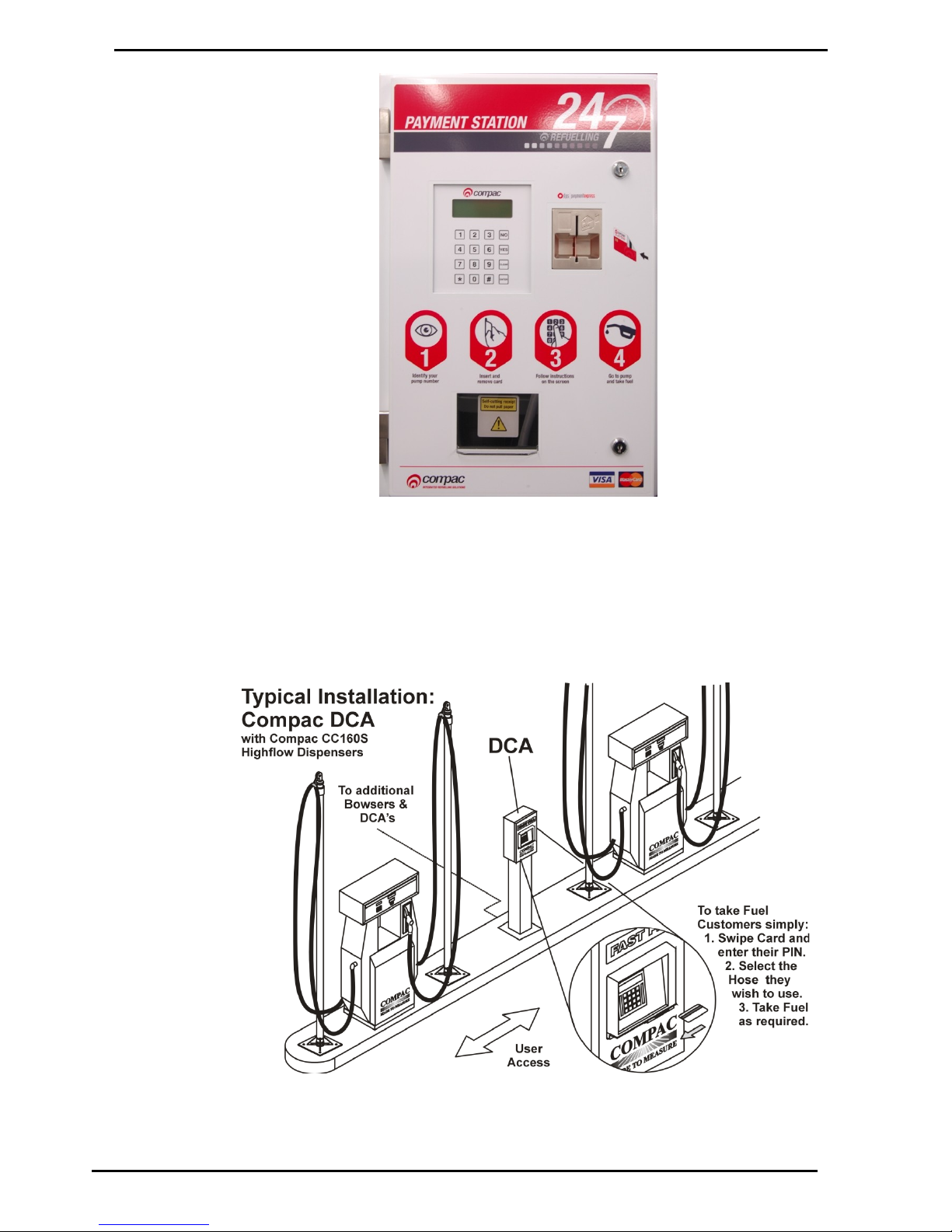
Figure 1: CC DCA Front View
Page 14

Introduction
Compac Industries Ltd.
Page 14
www.compac.co.nz
Litres Total
From July 2012, Compac dispensers that are connected to Compac fuel
management systems (FMS) that do not have a customer receipt printer,
are fitted with an additional display line labelled "Litres Total". This display
shows the total amount of fuel dispensed from the site to the authorisation
card or ID tag. The total is shown as litres to two decimal places.
Use
When a PIN number is entered, authorisation card swiped or an ID tag
detected by the fuel management system, the selected dispenser will
display the current total litres dispensed to the card (or ID tag) by the site
FMS.
The total will update as fuel is dispensed. When the transaction has been
completed, the new total is stored in the fuel management system. The
next time the card is swiped or ID tag detected by the FMS, the current
Litres Total will display on any of Litres Total capable dispensers on the
site.
The displayed total only relates to the amount of fuel
dispensed to the individual card or tag on that particular site.
Standalone
If the dispenser is set to standalone mode, the authorisation unit is
bypassed and no totals are recorded against the card or ID tag.
Software
The dispensers with Litres Total capability run software version 29255.
Fuel management systems manufactured after July 2012 have Litres Total
capability. Systems manufactured earlier than this require a software
upgrade.
Page 15

Installation Guidelines
Compac Industries Ltd.
Page 15
www.compac.co.nz
Installation Guidelines
You must be properly qualified, trained and authorised to install this
unit. Ensure you are qualified to perform each of the operations described.
Location
The Compac DCA is NOT suitable for mounting in a hazardous area.
Please consult the site's zone drawings to find the exact positions of the hazardous
areas for each particular site.
For adequately ventilated fuel dispensing sites (not including CNG/NGV), in most
cases the following will apply:
The unit is not designed to be constantly exposed to the elements. A canopy or
shelter should be installed to protect it.
The card reader and PIN pad should face away from the prevailing wind
especially in dusty or wet areas.
In areas experiencing extremes of weather (heat, cold, wind, rain, salt spray
etc.) consideration should be given to installing additional shelter.
The DCA location or protection should be such as to minimise the possibility of
damage from vehicles, trailers, boats, or the like.
On heavy vehicle sites, mounting the unit on a raised pad and/or installing
bollards to help protect from damage.
If mounting on a post, the base needs to be attached to a smooth, level surface
of sufficient strength to securely hold the retaining bolts or fasteners.
The DCA should be placed at least 8 metres from any above ground flammable
liquid storage or handling facility other than a dispenser.
The DCA should be placed at least 0.5 metres from any flammable liquid fuel
dispensers and 1.5 metres from any LPG dispensers.
The DCA should be mounted so that the base of the cabinet is at least
1.2 metres above the ground. If mounted on the post supplied by Compac it will
be 1.2 metres high.
Whenever running a cable through the post into the base of the cabinet always
ensure that the cable entry into the cabinet uses a vapour tight gland.
If the DCA post is within 4 metres of a dispenser or within 1 metre of the end of
any fuel dispenser hose, then the entire interior of the post may be considered a
hazardous area. Any cables running through, or electrical equipment mounted
in the post should be suitable for that hazardous area (refer AS/NZS 2381).
Generally the area below the DCA may be a hazardous area and therefore
some appropriate signage may be required e.g. no smoking.
Lighting should be provided during the hours of operation. Lighting should be
sufficient to provide safe working conditions that include, but are not limited to,
clear visibility of all markings on packages, signs, instruments and other
necessary items.
A minimum value of 50 lux is recommended.
These requirements do not apply to any specific site but are merely
recommendations that will apply in most cases. The owner/installer must ensure that
the installation complies with AS/NZS 3000, AS 1940, and any other applicable
regulations.
Page 16

Installation Guidelines
Compac Industries Ltd.
Page 16
www.compac.co.nz
Guidelines for Mounting the
DCA on a post
If a post is part of the installation:
Make sure you have all the appropriate wiring (power, pump comms, modem, printer
etc) led to the location where you are mounting the DCA.
The post assembly should include the following parts:
Galvanised base
DCA post
Back panel for DCA post
Flange with 4 studs
Nuts, washers and spring washers for studs
Button head cap screws for back plate
Level and securely mount the galvanized post base using appropriate fastenings for
the surface it is being mounted on. The mounting plate has 4 x 19 mm holes for
fastenings.
Due to the different surfaces that the DCA can be mounted on,
Compac does not supply fastenings for the base plate. Installers should use
fastenings suitable for the individual situation.
Attach the post to the base with the 4 coach bolts provided.
Feed all wires through the base plate
Place the DCA cabinet on top of the post and line up the mounting holes in the
cabinet to the holes in the base.
Insert the flange into the post, push the studs through the holes and fasten the
cabinet to the post using the 4 washers, spring washers and nuts.
Use only the Compac supplied 4 bolt mounting plate to secure the
DCA to the post.
Feed the wiring into the DCA cabinet using appropriate glands and plug any unused
holes in the cabinet.
Mount the cover plate onto the post using the supplied button head cap screws. The
cutout goes to the bottom of the post.
No open holes in the base of the DCA cabinet are permitted. Any
unused holes in the bottom of the DCA cabinet must be blanked.
Guidelines for Mounting the
DCA on a Wall
If the DCA is to be mounted on a wall, it needs to be attached to a bracket that bolts
to and supports the unit from underneath. No holes are to be made in the back of
the cabinet unless specifically approved by Compac. All wires into the cabinet must
be glanded and all unused holes in the base must be blanked.
Security Guidelines
To help prevent the possibility of unauthorised tampering, it is recommended that
tamper resistant fasteners be used and that all wiring outside the cabinet be
enclosed.
Page 17

Electrical Connections
Compac Industries Ltd.
Page 17
www.compac.co.nz
Electrical Connections
Gland the Mains and Comms SWA cables up through the post into the 20mm holes
provided in the bottom of the DCA cabinet.
Cable recommendations
Dial up or ADSL modem (if fitted): 2 core Steel Wire Armour (SWA).
Audit Trail Printer (if fitted): 4 core shielded data cable.
Direct Host (if fitted): Standard 9 pin serial cable.
230V Mains
3 Core Steel Wire Armour Cable 2.5 mm2. 230 Volts, 10A, 50 Hz
Connect the incoming mains to the circuit breakers as follows:
All terminals marked “N” are common.
All terminals marked “P” are common.
Connect the Earth to the busbar at the bottom of the cabinet
Generator power
If the unit is connected to a generator or an unstable power supply, please refer to:
Precautions when using generator power (see page 18).
Pump Comms
2 Core Steel Wire Armour (SWA) cable 1.5 mm2.
Connect pump comms cable to the terminals marked as follows:
CC for Compac and PEC protocol pumps
GG for Gilbarco protocol pumps
EE for Email protocol pumps
Total cable length in the comms circuit should not exceed 100 metres.
Compac, PEC and Email protocol pump comms are wired in parallel.
Gilbarco protocol pumps are wired in series.
If the site is active, do not connect pump comms until the correct price
has been entered into the DCA.
Phone or ADSL
Connect the lines to the terminals marked T, R and G
Comms Lightning Protection
If lightning protection is fitted on the Compac comms, connect the comms cable
directly into terminals marked LINE. Match up cables to the colours at the other end
of the lightning protection unit.
Tank Gauging (option)
Connect the wires from the tank gauging unit to the terminals on the Din rail marked
Tx Rx and G. The Tx wire from the tank gauging unit connects to the Rx terminal.
Cable length should be less than 3 metres.Cable length can be extended up to 10
metres if an opto-isolator is used. Part number FO-TEST-0001
Mechanical Registers
Refer to the specific instructions for the individual unit.
Ensure the perspex cover is refitted after cables are connected.
Page 18
Compac Industries Ltd.
Page 18
www.compac.co.nz
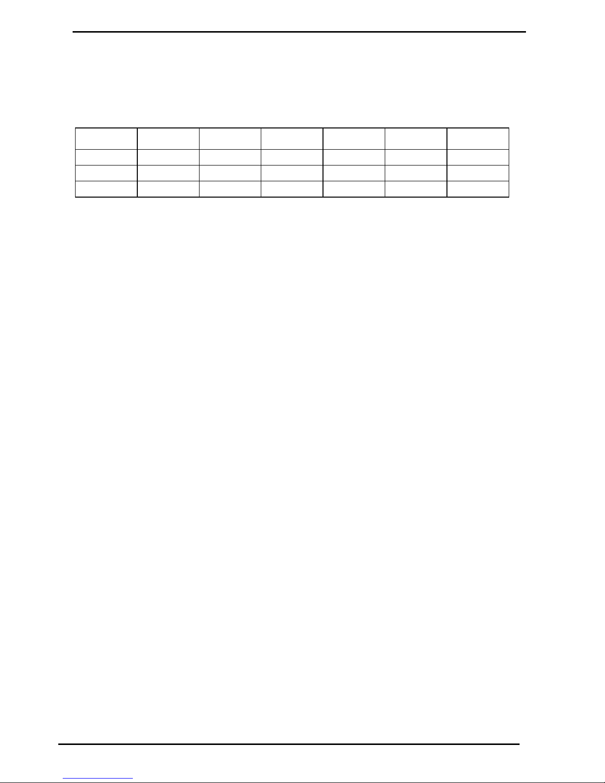
Tank Gauging Setup
Tank gauging is wired into the terminals marked Tx, Rx and G.
The tank gauging unit will have to be set up with the correct outputs to
communicate with the FMS board. Settings depend on the unit.
Type
Mode
Baud Rate
Parity
Bit
1 Stop Bit
Handshake
Veeder Root
Serial
1200
Odd
7 Bit
Yes
Off
Franklin
Veeder Root
9600
No
8 Bit
Yes
Off
Colibri
Veeder Root
9600
No
8 Bit
Yes
Off
The Compac settings for each model of tank gauge are usually either set at the
factory or sent via CompacOnline.
Precautions when using Generator Power
The power output from onsite generators can cause power spikes that may
damage electrical components within the cabinet. When connecting to sites
powered by generators, please take the following precautions:
Install power conditioner
Although generators are fitted with power regulators, most are not filtered
sufficiently for powering sensitive electrical components. We recommend installing
a commercial power conditioner and/or UPS between the generator and the unit.
Start up
1. Before starting a generator, make sure the power to the unit is turned off.
2. Start the generator, let the generator reach stable operating speed and wait
30 seconds before reconnecting the power to the unit.
For units where the generator starts and stops on demand, install a delay timer or
PLC to automatically isolate the unit until the operating speed and consistent
power output is achieved.
Shut down
Isolate the unit before shutting down the generator.
Page 19
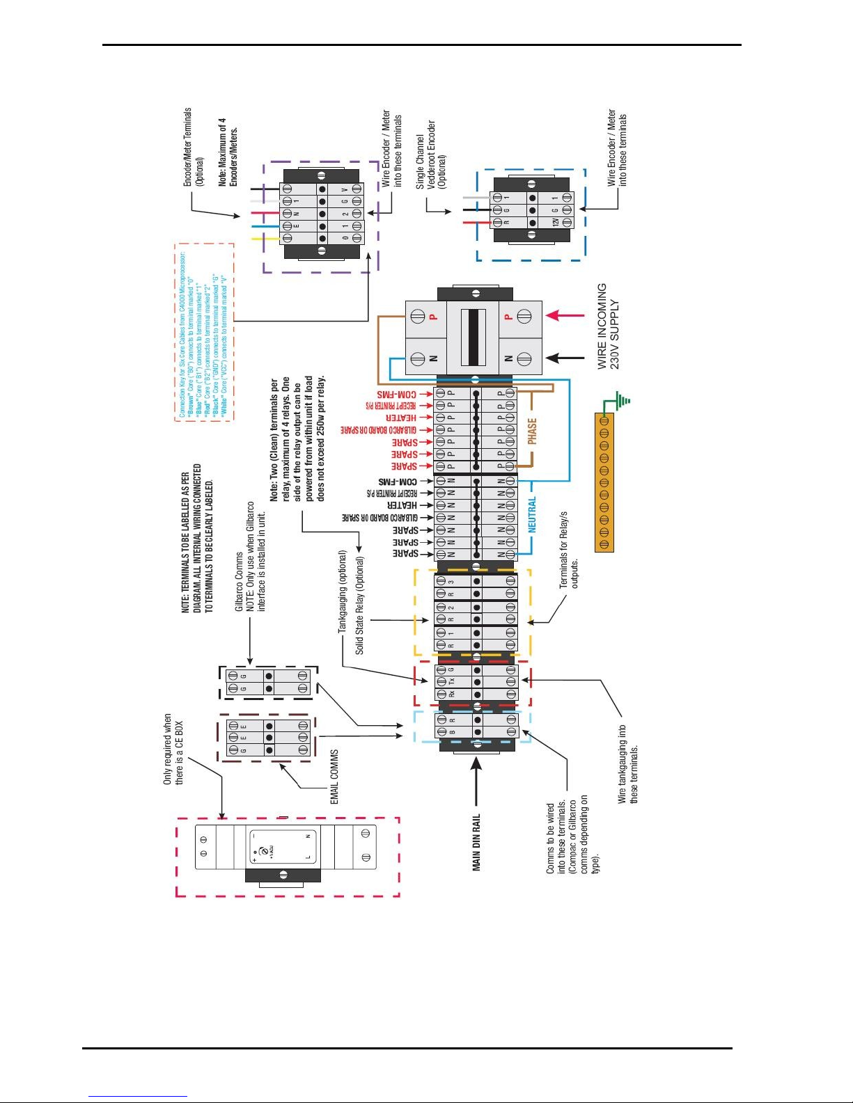
Wiring Diagram
Compac Industries Ltd.
Page 19
www.compac.co.nz
Wiring Diagram
Page 20

Compac Industries Ltd.
Page 20
www.compac.co.nz
Modem Connections
Dial In 56 K Modem
The phone line into the DCA cabinet should be 2 core Steel Wire Armour (SWA).
Gland and terminate this cable into the connector on the left hand side of the DIN
rail. Apart from the telephone line, the modem is pre-wired at Compac.
ADSL Modem
ADSL communication requires an ADSL enabled phone line and a Lantronix board.
The Lantronix board is installed and pre-wired at the factory if an ADSL capable
DCA is ordered.
The phone line is connected to the DCA in the same manner as the 56K modem.
3G (NZ) or NextG (Aus)
Modem
The 3G modem (if fitted) is prewired and only requires a SIM card to be fitted.
To fit the SIM card
1. Using a pin or small screwdriver, press the small yellow button in the hole next
to the SIM card tray. The SIM card tray will pop out.
2. Remove the black plastic SIM card tray.
3. Insert the SIM card.
4. Refit the SIM card tray.
There is a red diagnostic LED on the end of the Cell modem which will
initially be permanently on but will start to flash when the Cell Modem is connected
to the Network.
If upgrading from a dial-in cell modem, a Lantronics board is required.
Cell Modem - Dial In
The Cell modem is no longer sold. To change a SIM card:
1. Depress the small yellow button on the top of the cell modem.
2. Remove the black plastic SIM card-holder.
3. Insert the SIM card.
4. Refit the SIM card holder.
There is a red diagnostic LED on the end of the Cell modem which will
initially be permanently on but will start to flash when the Cell Modem is connected
to the Network.
Page 21

Modem Connections
Compac Industries Ltd.
Page 21
www.compac.co.nz
Direct Host
If the DCA is to be connected directly to the PC without a modem, a cable with a 9
pin female d-connector each end is available as an option. This may be cut and
additional cable spliced into it to make up the required length up to a maximum of 9
metres.
At the DCA it plugs into the socket marked “Modem”. The wiring for this cable is as
follows:
DCA PC
Pin 2 to Pin 3
Pin 3 to Pin 2
Pin 5 to Pin 5
Distances greater than 9 metres may require RS422 or RS485
converters.
Audit Trail Printer
If an Audit Trail / Report printer is part of the installation, plug the data cable into the
9pin D connector located in the top left hand corner marked 'Audit Printer'
The Yellow LED CTS/2 on the processor board should come on to
indicate that the printer is connected
Page 22

CWID Key & CWID Block Readers
Operating Instructions
Compac Industries Ltd.
Page 22
www.compac.co.nz
Operating Instructions
CWID Key & CWID Block Readers
Overview
Compac authorisation units can be equipped with a Compac Wireless
Identifier (CWID) sensor. Drivers with CWID keys can place their key close to
the sensor to enable the pumps. The CWID keys have unique numbers so
that each transaction can be assigned to a particular CWID.
CWID block transceivers can also be mounted on the pump nozzle so that
the pump is authorised automatically when the nozzle is inserted into a fuel
tank fitted with a CWID key. The unit can be programmed to cut out if the
CWID signal is lost for 10 seconds in order to prevent filling of unauthorised
vehicles.
Standard CWID Key Operation
The driver goes to the unit and places their CWID key close to the CWID
"target". If the CWID is valid, the display will request PIN entry [optional] and
Odometer entry [optional].
If more than one pump is available, the display then requests the driver to
select which pump they wish to refuel from.
The display then advises the driver to take fuel.
After the transaction, if the unit is equipped with a receipt printer and the
driver requires a receipt, he/she goes back to the unit and re-presents their
CWID key. Select YES to print receipt. (If NO is pressed, a new transaction
will be started.)
After printing, the driver lifts the sliding door to retrieve receipt. The receipt is
cut off automatically.
CWID Block Nozzle Mount
Operation
The driver goes to the pump and inserts the nozzle into the fuel tank. The unit
recognises the key and starts the pump.
If the nozzle is removed from the filler, the unit will shut the
pump down after approximately ten seconds. This it to prevent the filling of
unauthorised tanks.
When refuelling is complete, the driver hangs up the pump nozzle and
departs.
Setup
The CWID aerial is tuned for best performance at the factory. If the CWID
board or aerial is replaced then the aerial must be re-tuned. Follow the
instructions for Tuning the Aerial (see page 105)
Page 23
Operating Instructions
CWID Key & CWID Block Readers
Compac Industries Ltd.
Page 23
www.compac.co.nz
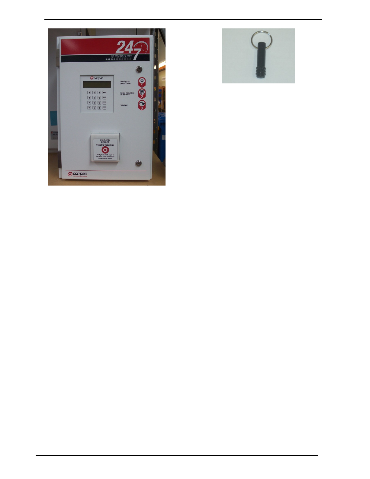
Figure 2: DCA with CWID Key Reader
Figure 3: CWID Key
Page 24
HID Readers
Operating Instructions
Compac Industries Ltd.
Page 24
www.compac.co.nz
HID Readers
Overview
Compac authorisation units can be equipped with an HID reader. Drivers
with HID keys can place their key close to the sensor to enable the pumps.
The HID keys have unique numbers so that each transaction can be
assigned to a particular key.
Standard HID Key Operation
The display on the unit will read "PASS HID KEY"
The driver goes to the unit and places their HID key close to the HID panel
on the unit. If the HID key is valid, the red light at the top of the sensor will
turn green and beep once.
If the unit is configured to ask for a customer ID, odometer reading or job
number it will read: "ENTER CUSTOMER ID", "LOAD ODOMETER AND
PRESS ENTER" or "ENTER JOB NUMBER".
When the correct numbers have been entered the display will read: LOAD
PUMP NUMBER AND PRESS ENTER". The driver selects the pump
number he wishes to use and presses enter. The display will now read:
"GO TO PUMP AND TAKE FUEL". (If the pump number selected is not one
connected to the unit or the pump is switched off, the display will read:
"PUMP OFF LINE".)
The driver will then take fuel and then hang up the nozzle, this completes
the transaction.
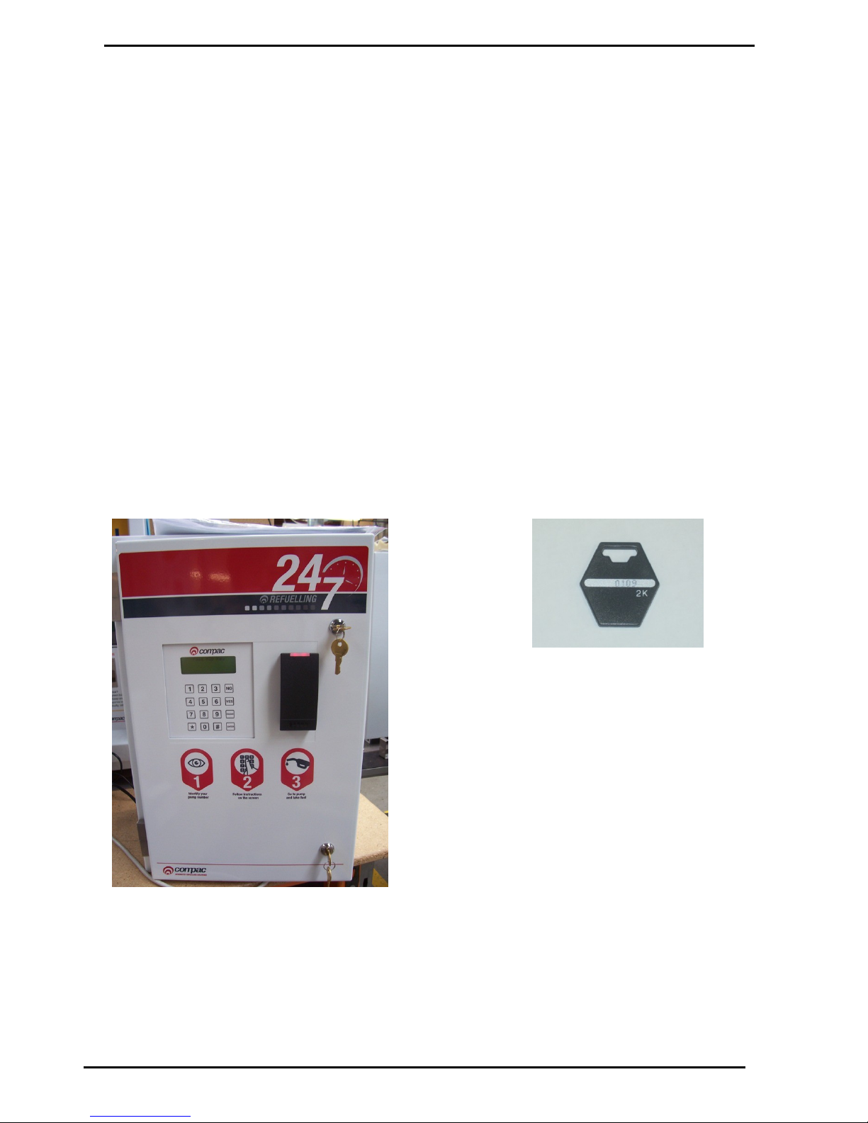
Figure 4: DCA with HID Reader
Figure 5: HID Key
Page 25

Operating Instructions
iTrack Reader
Compac Industries Ltd.
Page 25
www.compac.co.nz
iTrack Reader
Overview
The Compac unit can be supplied with an iTrack reader that detects vehicles
fitted with an authorised transponder and authorises the pump to dispense
fuel.
Standard iTrack Operation
When the driver drives up to the pump the iTrack reader will sense the
presence of an authorised vehicle. Depending on site setup the unit display
will request PIN entry [optional], Odometer entry [optional] and which pump
they wish to refuel from [optional].
The display then advises the driver to take fuel.
After refuelling, if the unit is equipped with a receipt printer and the driver
requires a receipt they select YES to print receipt. (If NO is pressed, a new
transaction will be started.)
After printing, the driver lifts the sliding door to retrieve receipt. The receipt is
cut off automatically.
The driver then drives away from the pump. The pump is now ready for the
next transaction.
Page 26
iTrack Reader
USB Module
Compac Industries Ltd.
Page 26
www.compac.co.nz
USB Module
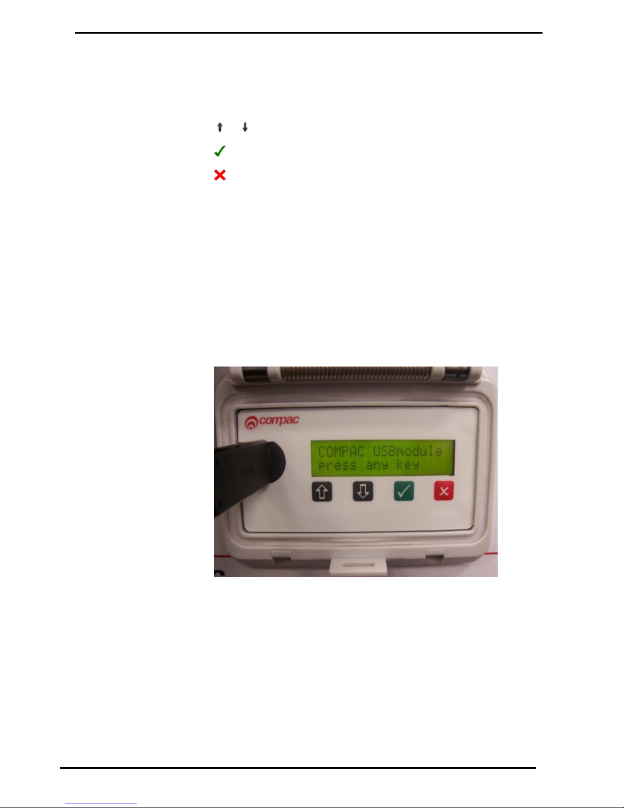
The USB Module is mounted in a plastic enclosure with a sealed lid. Under the lid is
a slot for a USB stick, an LCD display and four buttons:
and arrows toggle between the screens
accepts the Yes/No option displayed
rejects the Yes/No option displayed and returns to the "press any key" screen
The screens available for uploading and downloading are:
Set Price - Upload new price schedule from USB stick
Send Cards - Uploads new card authorisation files from USB stick
Get Trans - Downloads all untagged transaction details to the USB stick
Get Buffer - Downloads all transactions in the memory to the USB stick
including previously downloaded transactions. (This could be up to several
thousand transactions.)
Get All - Uploads and downloads all the above files
The USB module and key can be used while the unit is in operation.
While not recommended, if the USB key is removed while in use, no transaction
data will be lost. If the USB key is removed, the operation will need to be repeated to
ensure all the data stored on the unit is retrieved.
Figure 6: USB Module
Page 27
USB Module
USB Memory Stick
Compac Industries Ltd.
Page 27
www.compac.co.nz
USB Memory Stick
The Compac USB Module comes with a USB stick that has already been
programmed for the customer with a unique file number. The number is located in
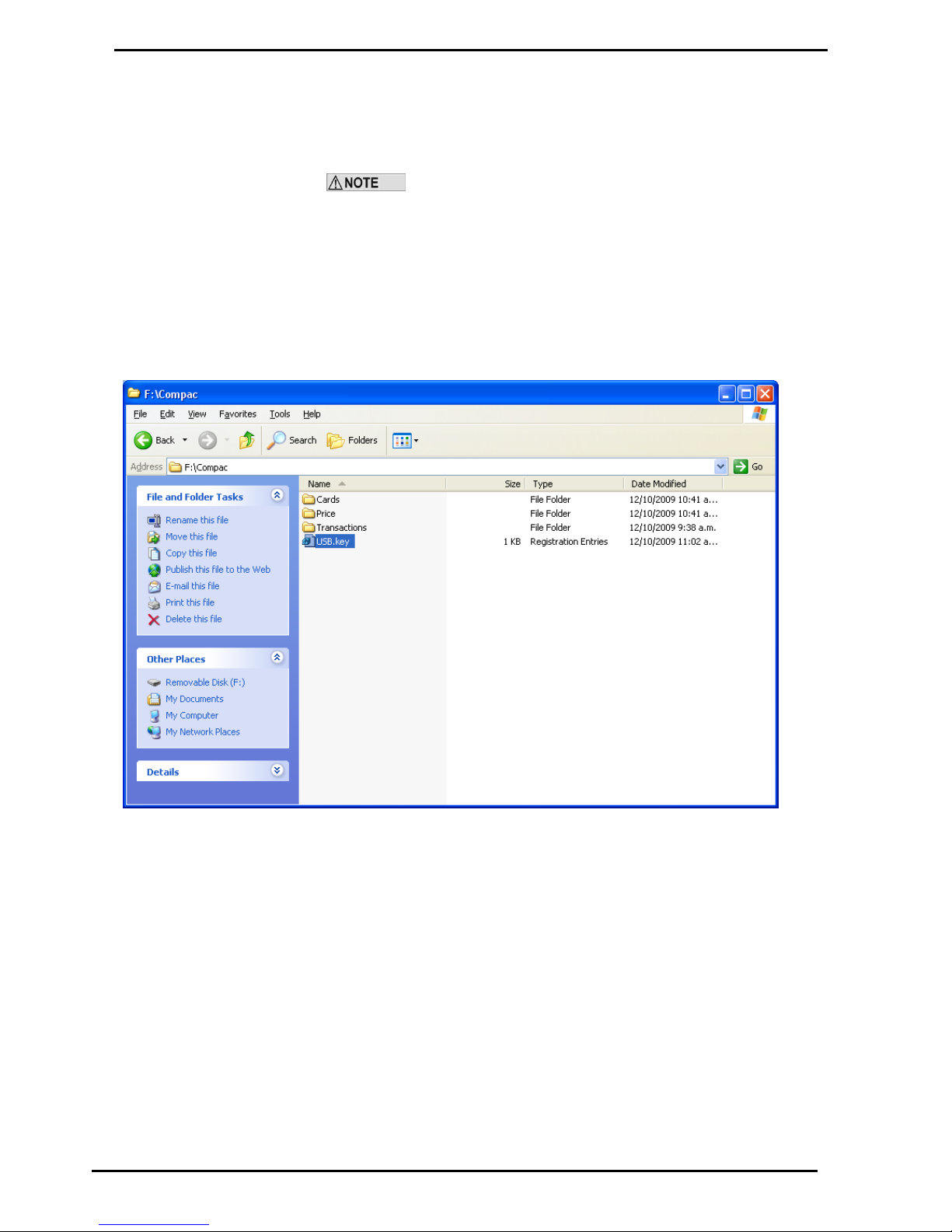
the Compac folder and will allow the USB module to recognise the USB stick.
Each module must have its own key. You cannot have one USB key
that covers multiple units.
You should always keep a secure copy of this file as if you lose your Compac USB
stick the USB Module will not recognise any other USB stick unless it contains the
unique “USB.key” file in the Compac folder.
It is also good practice to keep a secure copy of the Cards folder and Price folder if
you are setting up the price through the USB.
The USB Module will display a “Non-Secure USB” error message if the USB Stick
does not have the “USB.key” file or the file is not under the Compac folder.
For instructions on handling these files refer to: Working With USB Module Files
(see page 32)
Page 28
USB Memory Stick
Uploading and Downloading Files
Compac Industries Ltd.
Page 28
www.compac.co.nz
Uploading and Downloading Files
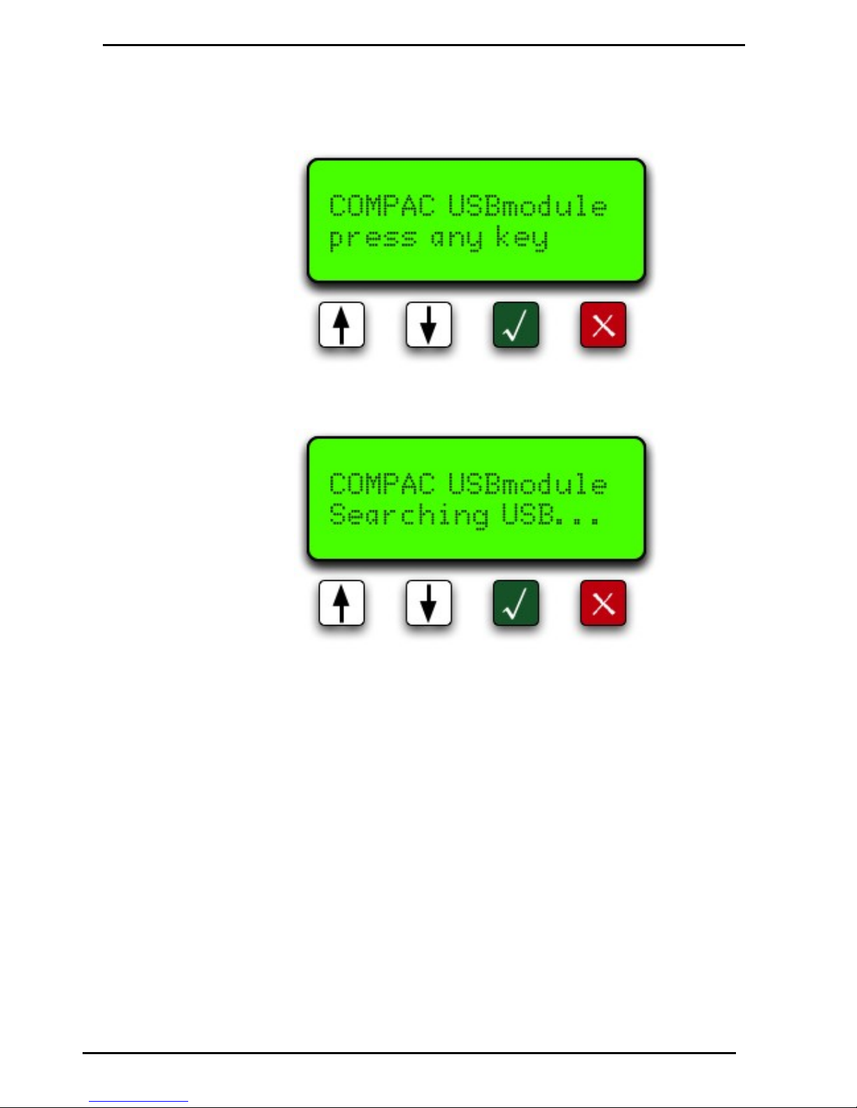
To use the USB Module lift the plastic cover of the module. The screen should
display: “COMPAC USB module press any key”.
Plug your USB stick into the USB slot and push any of the keys. It will then display
“Searching USB...”.
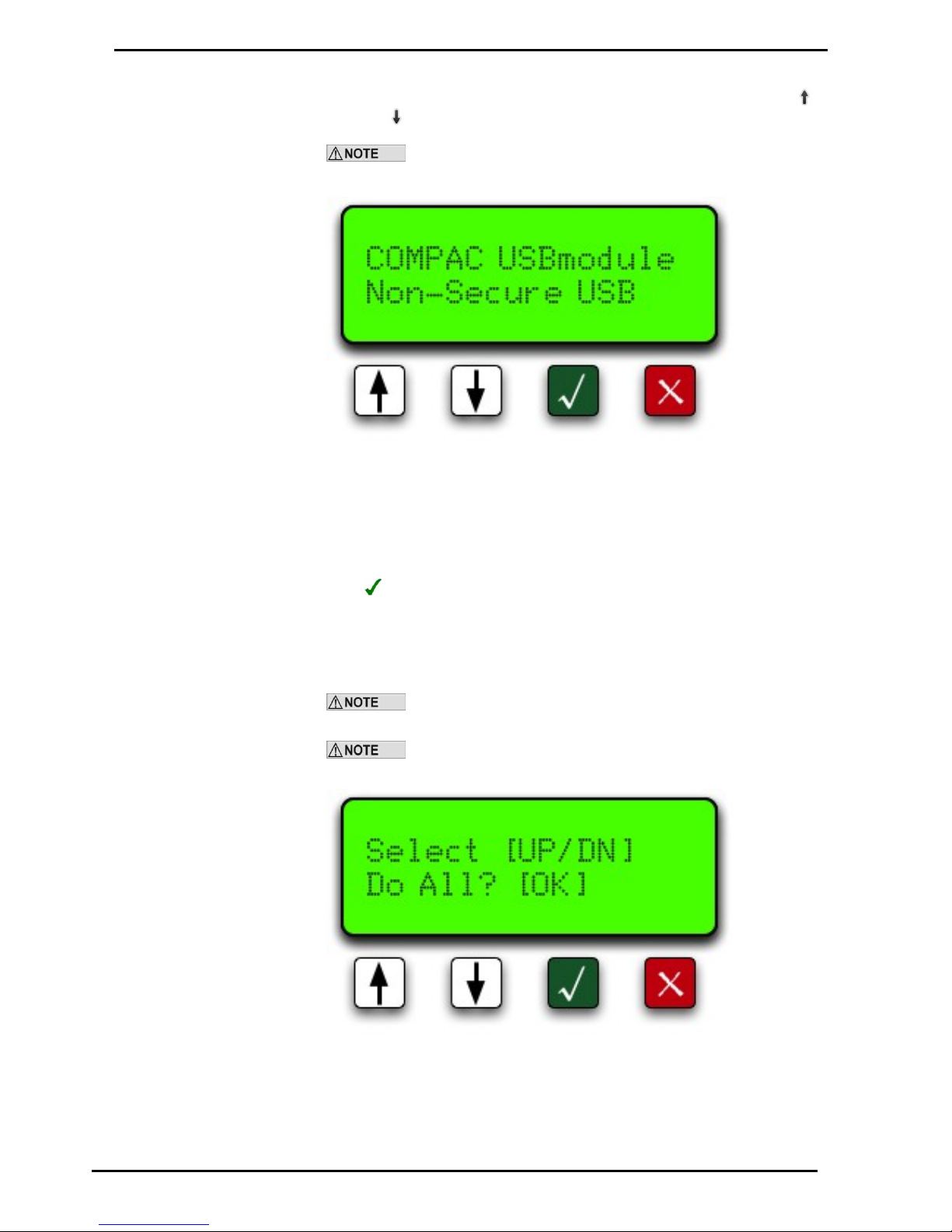
If the USB stick does not contain the Comapc USB security code the display will
read "Non Secure USB". You will have to load the "USB Key" file onto the key before
it will work.
Page 29
Uploading and Downloading Files
1) Do All
Compac Industries Ltd.
Page 29
www.compac.co.nz
If the USB stick has the security code and it has found the data on the USB stick, it
will display “Select [UP/DN] Do All? [OK]” Refer to the screen Do All. Use the up
and down buttons to go through the menu on the USB Module.
If the USB Module can’t find the USB stick, pull it out and push it in
again.
1) Do All
“Do All” uploads the cards files and price files from the USB stick to the module and
downloads transactions and buffers from the module to the USB stick. Push the
green button to start the operation. The unit will read “Please wait...” while it’s
uploading transaction and buffer files and downloading cards and price files. Be
patient.
If you do not want to use this function, use the up or down keys to scroll through the
other options.
Getting the buffer itself could take up to 5 minutes depend on how
many transactions are in the unit.
It is very important that you DO NOT unplug the USB stick before the
USB module says “Complete Remove USB”.
Page 30
2) Set Price
Uploading and Downloading Files
Compac Industries Ltd.
Page 30
www.compac.co.nz
2) Set Price
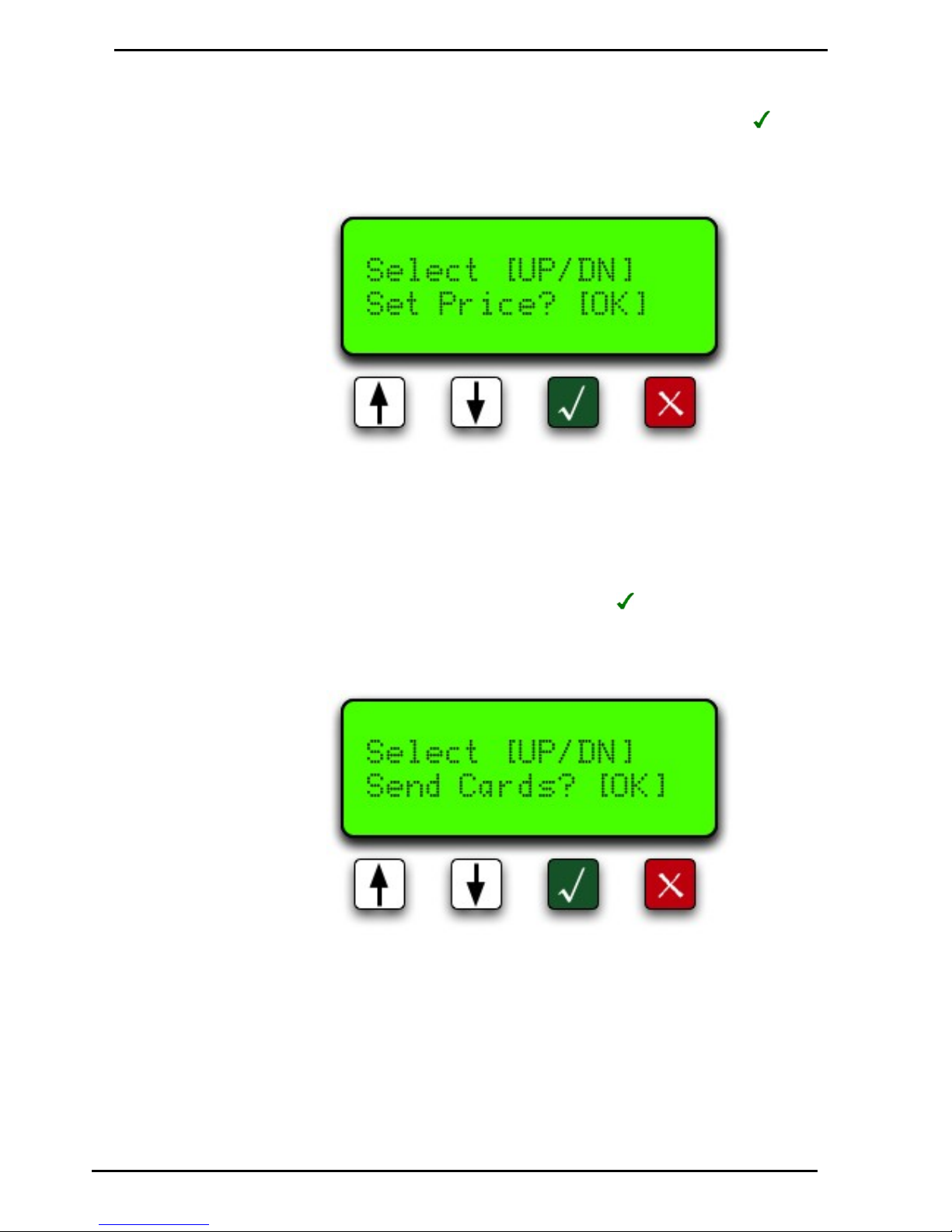
Push down button to move to the next option “Set Price”. Push the green button
to send the price file to the module. The unit will read “Please wait...” Once the file
has been uploaded to the unit it will say “Complete Remove USB”. You can now
either unplug the USB stick or wait a few seconds for the screen to return to the
menu to continue uploading or downloading more files.
3) Send Cards
The next option is “Send Cards”. Push the green button to upload the card files
to the module. The unit will read “Please wait...” Wait for the USB Module to say
“Complete Remove USB”. You can now either unplug the USB stick or wait a few
seconds for the screen to return to the menu to continue uploading or downloading
more files.
Page 31
Uploading and Downloading Files
4) Get Buffer
Compac Industries Ltd.
Page 31
www.compac.co.nz
4) Get Buffer
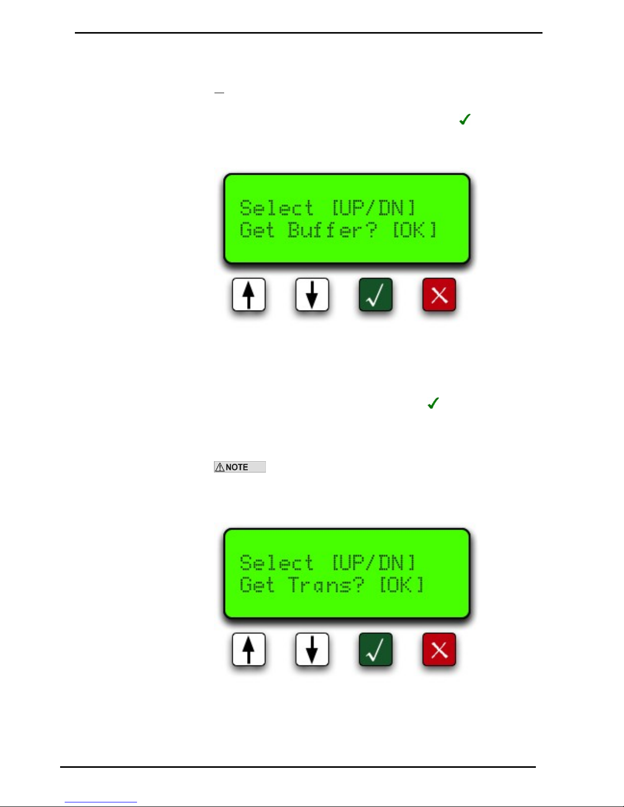
Move down to the next option “Get Buffer”. Use this option if you want to download
all the transactions from the module. This would include the old transactions that
have been downloaded from the module before. This operation could take up to 5
minutes depending on how long the unit has been trading and how many
transactions are held in the memory of the equipment. Push the button. The unit
will read “Please wait...” Wait for the USB Module to say “Complete Remove USB”.
You can now either unplug the USB stick or wait a few seconds for the screen to
return to the menu to continue uploading or downloading more files.
5) Get Transactions
The last option is "Get Trans"(actions). Push the green button to download
transaction file from the module to the USB stick. The unit will read “Please wait...”
Wait for the USB Module to say “Complete Remove USB”. You can now either
unplug the USB stick or wait a few seconds for the screen to return to the menu to
continue uploading or downloading more files.
Every time you download transactions from the equipment, it tags
them so they will not be downloaded again using this function. It also marks them as
re-writable so as the transactions fill up the memory, it will overwrite the old
transactions. Depending on functions, the equipment can store up to 5,000
transactions.
Page 32
5) Get Transactions
Working with USB Module Files
Compac Industries Ltd.
Page 32
www.compac.co.nz
Working with USB Module Files
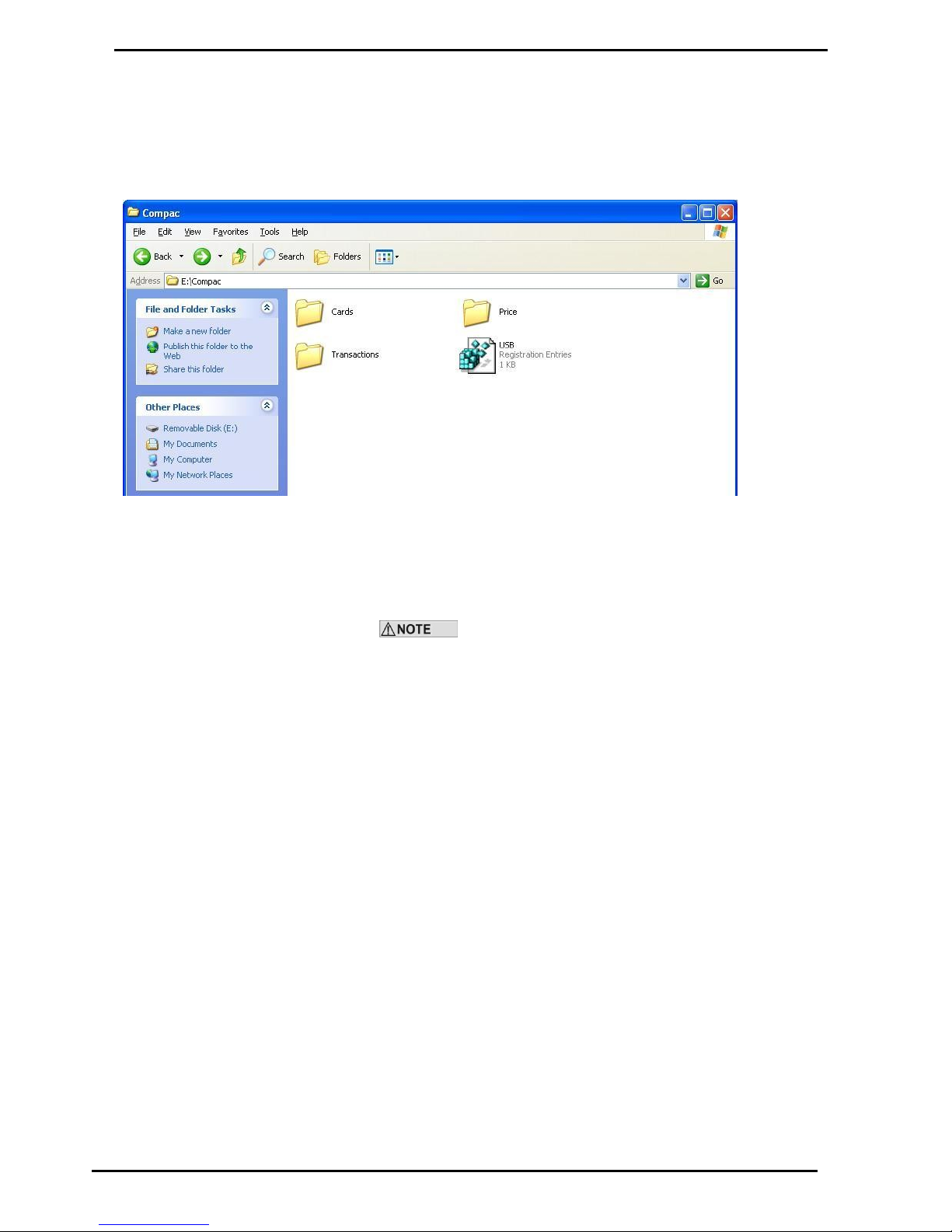
You can access the files on your USB key by plugging it into the USB port
of your computer and clicking on the Compac file.
You will see the following folders:
Click on the Cards, Price or Transactions files to view, change or retrieve
information.
Only transaction information is uploaded from the module.
Card and pricing information is stored on the key and downloaded to the
module when requested.
Figure 7: USB key folders
Page 33
Working with USB Module Files
1) Cards
Compac Industries Ltd.
Page 33
www.compac.co.nz
1) Cards
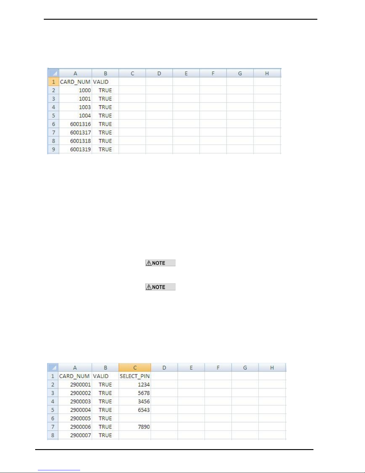
Opening the Cards folder will show the Excel spreadsheet file for the cards
called cards.csv.
Adding a Card
To add a card, enter the new card number in column A and the word TRUE
in column B. Save the changes. Next time the USB key is inserted in the
module and the Send Cards function selected, the new card number(s) will
be installed.
Deleting a Card
Change the appropriate field in column B to FALSE. Save the changes.
Next time the USB key is inserted in the module and the Send Cards
function selected, the card(s) will be deleted.
The module will upload card information from the USB key
and overwrite card information stored in the USB Module. The module
cannot download card information to the USB key.
It is not recommended to delete cards by deleting the card
information.
PIN Numbers
If you wish to use PIN numbers for added card security, you can add a new
column titled SELECT_PIN. (Depending on the set-up you ordered, this
may already be entered.) When a PIN number is added in this column, the
user will be prompted to enter their PIN number. If a cell in this column is
left blank, a PIN will not be asked for.
PIN numbers are 4 digits as standard.
Figure 8: Cards spreadsheet
Page 34
1) Cards
Working with USB Module Files
Compac Industries Ltd.
Page 34
www.compac.co.nz
User ID
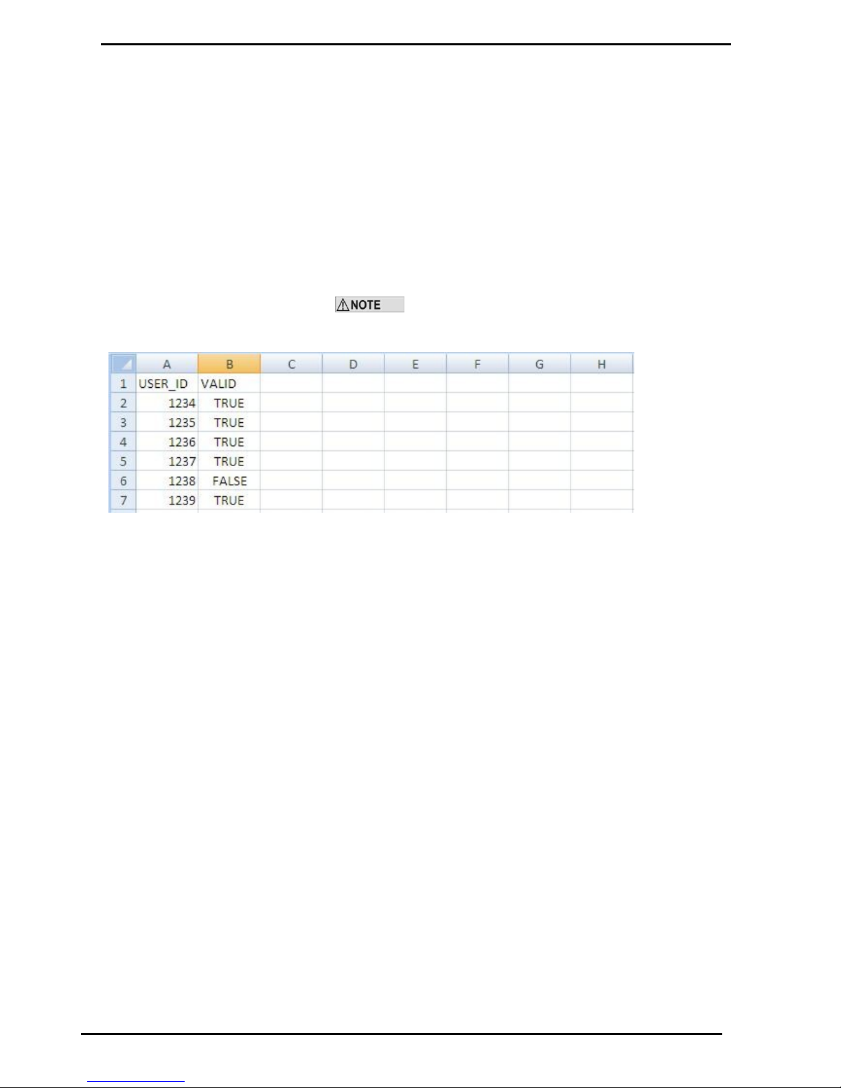
The unit can be set up to manage user ID numbers. It requires a change to
the configuration code of the unit and a new file called cardusers.csv added
to the Cards folder of the USB key.
When set up, the unit will prompt for a user ID number and then a PIN
number (if the card is set-up with a PIN).
Users are not linked to a particular card.
As PIN numbers are assigned to the card, all users will have to enter the
same PIN number.
To assist with administration, you can set up a column linking names to ID
numbers but this information will not be transferred to any reports.
It is not recommended to delete user IDs by deleting the
information. Use the word FALSE in the VALID column to remove the user
ID from the unit.
File Format
If the any of the above files are lost then a new file can be recreated by
duplicating the headers in row 1 (case sensitive). Enter the card fields and
save as a .csv file.
Page 35

Working with USB Module Files
2) Price
Compac Industries Ltd.
Page 35
www.compac.co.nz
2) Price
Clicking on the Price file will show the pricing spreadsheet. Click on the
icon to display the pricing information.
Changing Price
To change pricing, change the figure(s) in column B to the new value. ($
per litre) Next time the USB key is inserted in the module and the Set Price
function selected, the new price(s) will be installed.
The module will upload pricing information from the USB key
and overwrite the information stored in the USB Module. The module
cannot download pricing information to the USB key.
File Format
If the price file is lost then a new file can be recreated by duplicating the
headers in row 1 (case sensitive). Enter the pricing information and save as
a .csv file.
Figure 9: Pricing Spreadsheet
Page 36
3) Transactions
Working with USB Module Files
Compac Industries Ltd.
Page 36
www.compac.co.nz
3) Transactions
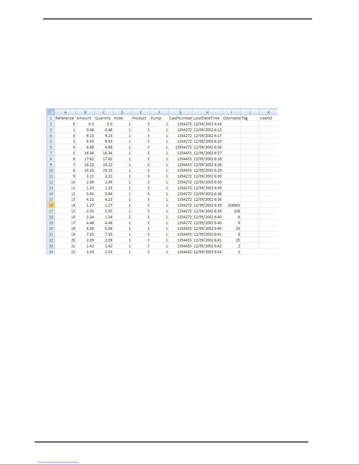
The Transactions folder has the downloaded transactions from the USB
module. Click on the file you wish to view.
To help you find the correct file the transaction files are named using the
following format: Transactions_Day (DD) Month (MM) Year (YYYY) Time
(Hours Minutes Seconds).TRA
Example: Transactions_30112009140653.TRA was created on the 30th
November 2009 at 2.06 and 53 seconds PM.
File Format
The files shown are as follows:
Reference - Every transaction is given a consecutive number from
initialisation of the USB module
Amount - The value of the transaction in local currency
Quantity - The amount of fuel dispensed in litres
Hose - The hose number used
Product - The product code number
Pump - The pump number
Card Number - The number of the card used for the transaction
Local Date Time - The date (DD/MM/YYYY) and time (24 hour clock)
of the transaction
Odometer - The odometer reading if entered
Tag - Information is shown here if the unit uses mapped cards
User ID - The ID number of the user if the unit is set up to prompt for a
number
Figure 10: Transactions file
Page 37
Working with USB Module Files
Compac Industries Ltd.
Page 37
www.compac.co.nz
Customising Your Transaction Reports
If you want to include more card information on your Transaction reports
we have developed an automated process to include card information in
your transaction file. This software requires an update to existing USB keys
that do not have it. The new software is called USBTransJoin.exe and as
its name suggests, it joins the card information on the USB key to the
transaction records
Software installation and setup
instructions
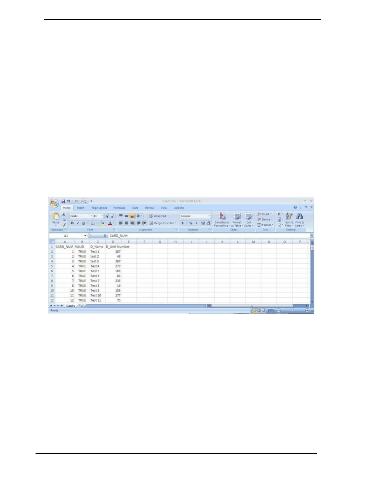
1. Copy the USBTransJoin.exe file onto the Compac USB key and put it
in the “Compac” Folder
2. In the “Cards” folder you will have a file called cards.csv . The two
standard columns in this file are “CARD_NUM” and “VALID”
3. To include information from this file into your transaction records you
will need to create new columns that start with the prefix “D_” . For
example, if you wanted to include the name and unit number of the
vehicle using cards you would add in two columns titles “D_Name” and
“D_ Unit Number”. See the screen shot below showing this example.
4. There is no limitation to the number of extra columns you add to the
card file however the “CARD_NUM” and “VALID” column must not
have their column names altered or other columns added to the left
hand side of them.
Page 38
Customising Your Transaction Reports
Working with USB Module Files
Compac Industries Ltd.
Page 38
www.compac.co.nz
How to use the software
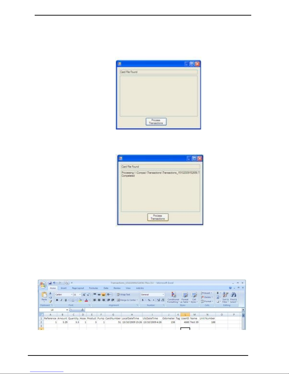
Run the USBTransJoin.exe software by double clicking on it. A dialog box
with appear with the message
“ Card file found”
Click on the “Process Transactions” button to merge the card information
with the transaction information. A conformation message will appear
showing the file path of the file created.
Browse to the transactions folder on the USB key, a new folder will have
been created titled “PostProcess”. Inside this folder will be a CSV file with
the merged transaction and card information. Any of the card information
fields with the “D_” suffix will appear on the right side directly after all the
normal fields that are in a transaction file. If you do not have any
information allocated to that card the headers will be in this file but there
will not be any information against that card. In this example below card
number 51 had the name “Test 39” and Unit number “188” assigned
against it.
Page 39
Powering Up
Compac Industries Ltd.
Page 39
www.compac.co.nz
Powering Up
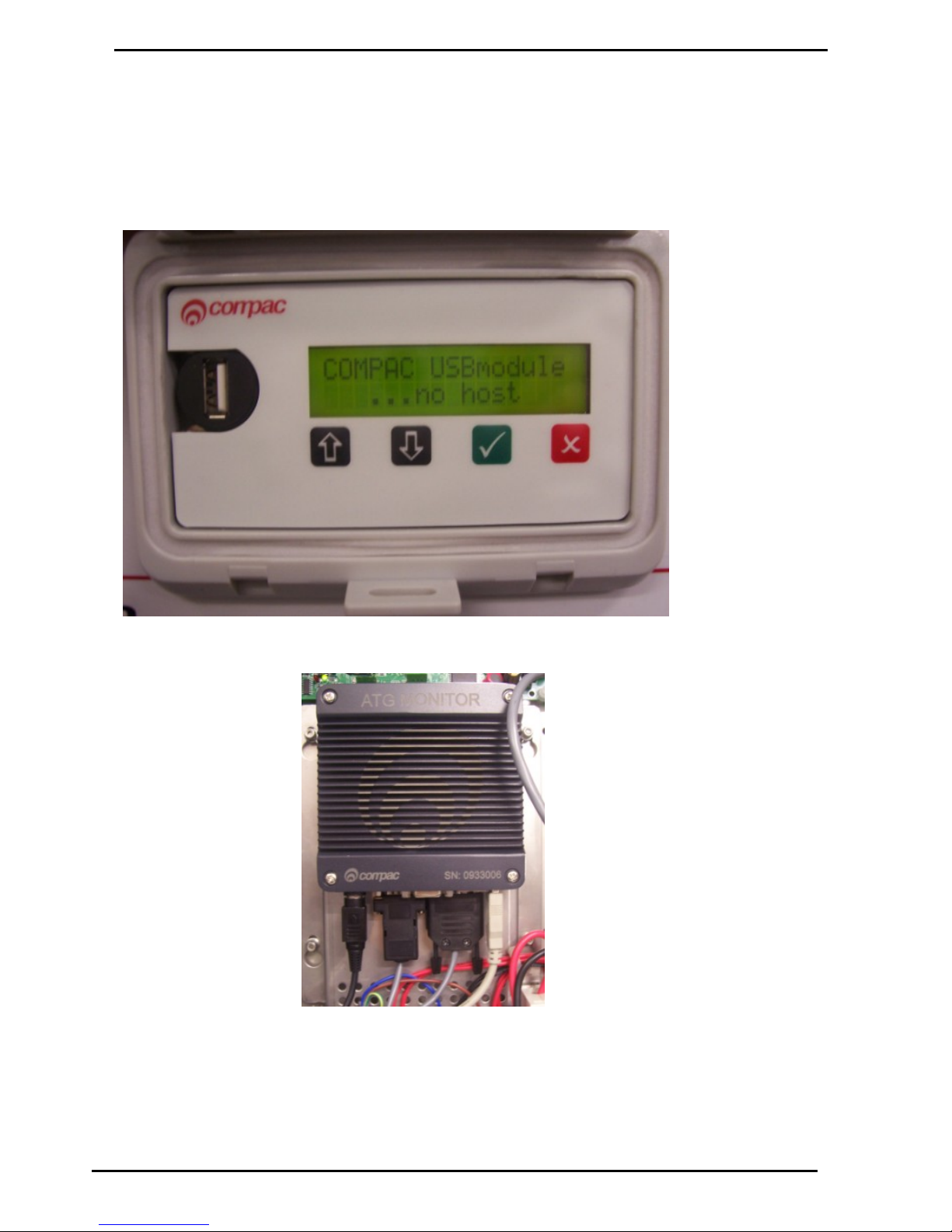
When you power up the USB Module it will display “COMPAC USB module
...no host” as the software has not started running yet. It should change
after 2 minutes or so and display the idle message saying ”press any key”.
If the no host message does not clear in 5 minutes, check all the cables are
plugged in to the Compac Box.
Figure 11: ....No Host Screen
Figure 12: Compac Box
Connections
Page 40
System Setup
Set Up
Compac Industries Ltd.
Page 40
www.compac.co.nz
Set Up
System Setup
The unit uses the ComFMS circuit board. All set up is done using the four line dot
matrix display on the PIN Pad.
Please contact your local Compac service agent if you have any problems.
The area where installers have the most difficulty is in setting up pumps and cards.
Where possible Compac will set up the Pumps and Cards in the unit during
manufacture. However as these details are not always available, some setting up
may be required on site
Refer to tables later in this manual for detailed instructions on how to
set up each parameter.
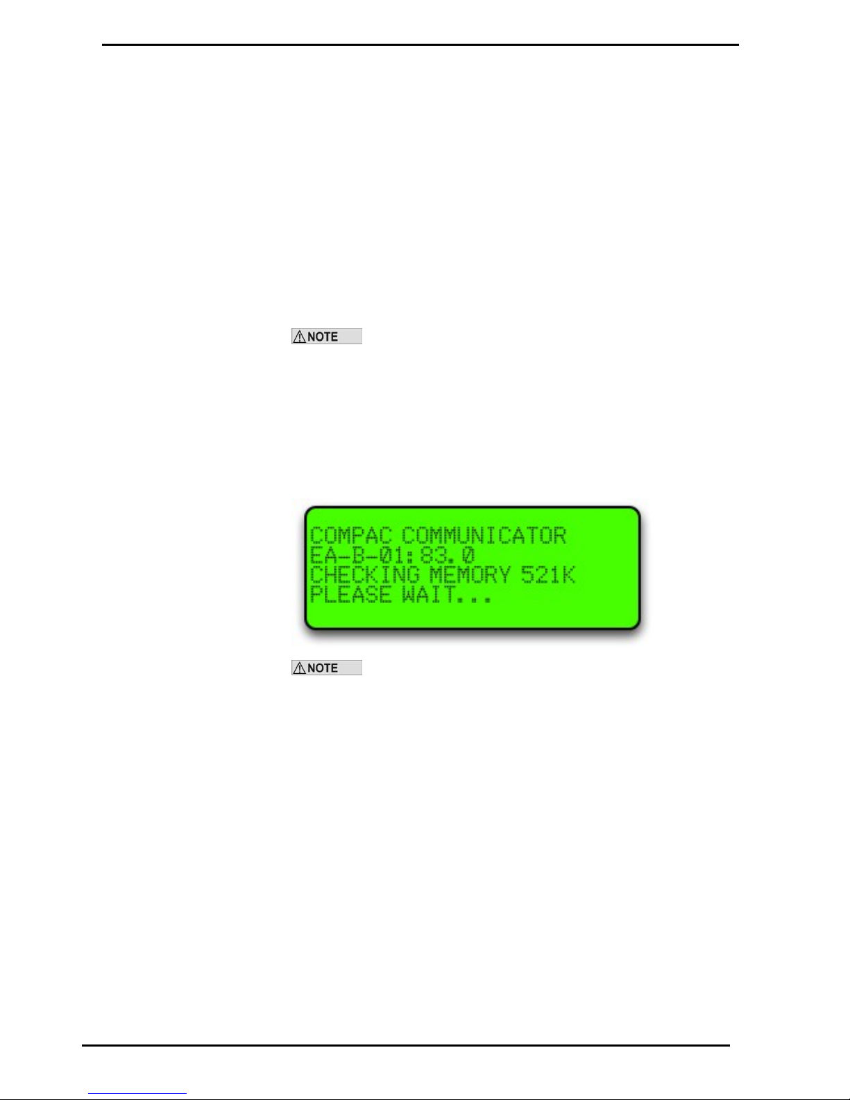
Software Identification
To identify the software versions installed in the unit, the eprom software version
and then the downloaded software version are shown on the display during powerup. The downloaded software version is displayed in the screen below.
Software version may differ from example shown above. Check with
help desk for the appropriate version for your unit.
Page 41
Main Menu Options
Option #1 REPORTS
Compac Industries Ltd.
Page 41
www.compac.co.nz
Main Menu Options
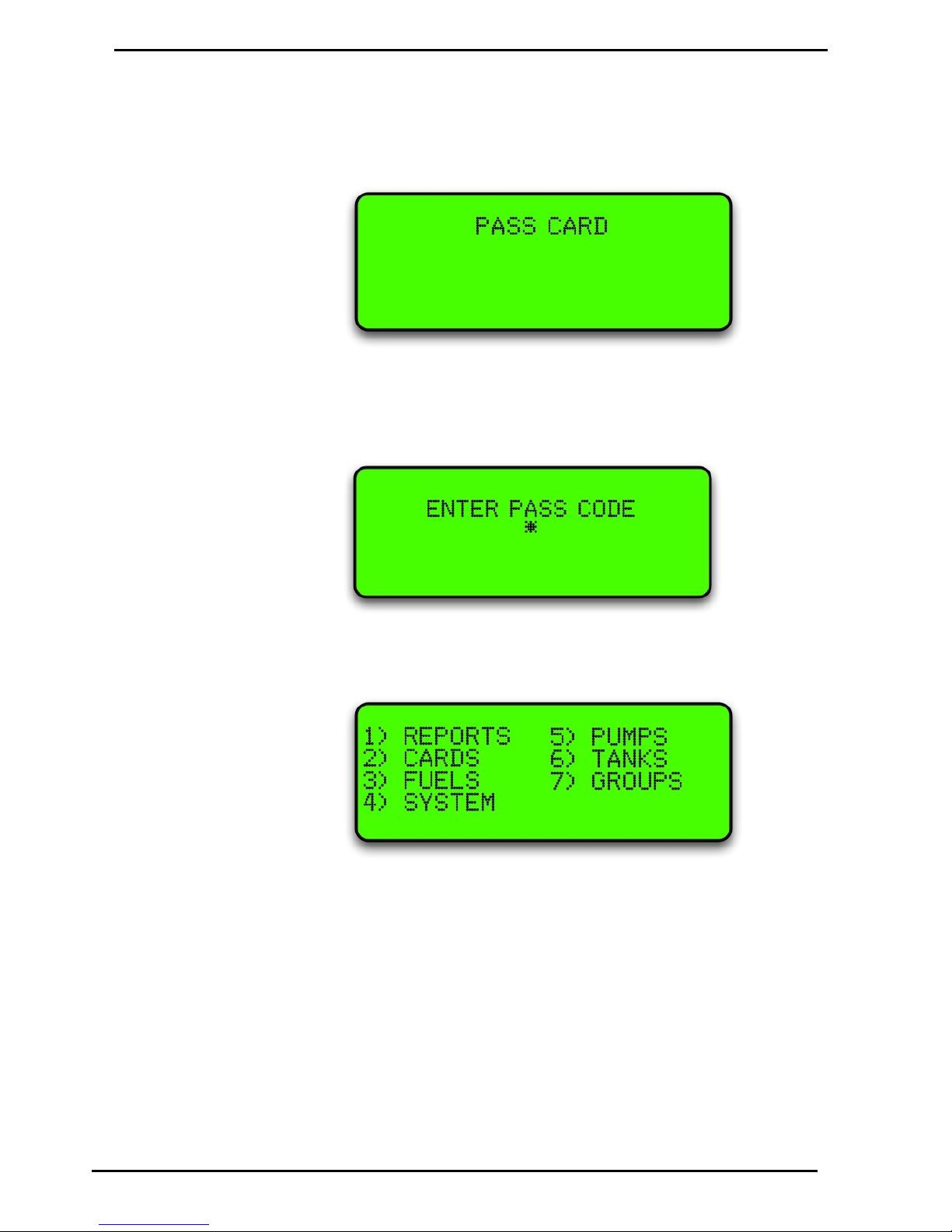
The following is usually displayed when the unit is not in use.
If setup is required, push <NO> and “ENTER PASS CODE” will be displayed. Enter
the pass code to access the main menu. (Factory default 654321). If you lose your
pass code, contact Compac to get it reset.
The following options are displayed:
Option #1 REPORTS
The reports menu is not used on current models. For old systems running audit trail
printers, contact Compac for setup advice.
Page 42
Option #2 CARDS
Main Menu Options
Compac Industries Ltd.
Page 42
www.compac.co.nz
Option #2 CARDS
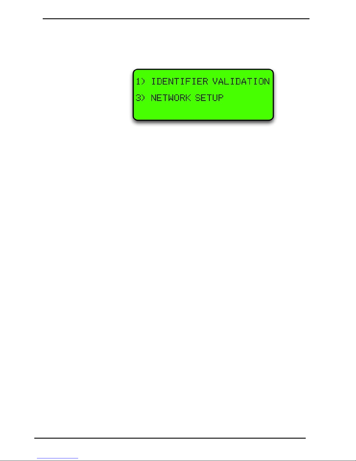
Selecting 2 Cards will bring up this screen
Choose 1 Identifier Validation to set up cards or 3 Network Setup to enter Access
and ISO settings
Page 43
Main Menu Options
Option #3 FUELS
Compac Industries Ltd.
Page 43
www.compac.co.nz
Option #3 FUELS
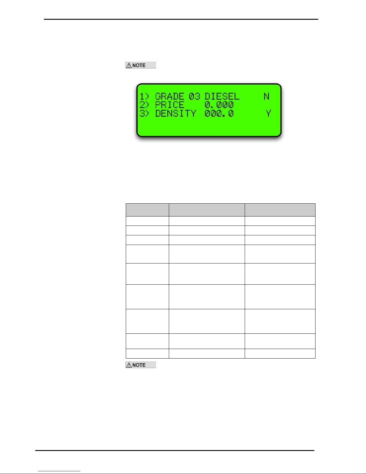
Selecting Fuels will bring up the following screen:
Depending on your software, the Density line may not show.
Use the Yes and No buttons to scroll through the fuel types.
To change the price for the fuel grade, press 2 and the price will start flashing
Enter the new price in a four digit format and press Enter.
The following table describes the process.
Keyboard Entry
Result on Display
Operation
Enter Passcode
<ENTER>
Main Menu is displayed
<3>
Fuel Menu is displayed
1) GRADE XX
2) PRICE 0.000
Change Price
<2>
1) GRADE XX
2) PRICE 0.000 (flashes)
Use the N and Y keys to
scroll up and down the
Grades
Type in new
price
1) GRADE XX
2) PRICE 0.000 (still
flashes)
<ENTER>
1) GRADE XX
2) PRICE 0.000 (stops
flashing)
<N> or <Y> to
change grade
Change another price
<CLEAR>
Returns to Main Menu
Escape
Manual pricing is overidden by USB or internet pricing.
Page 44
Option #3 FUELS
Main Menu Options
Compac Industries Ltd.
Page 44
www.compac.co.nz
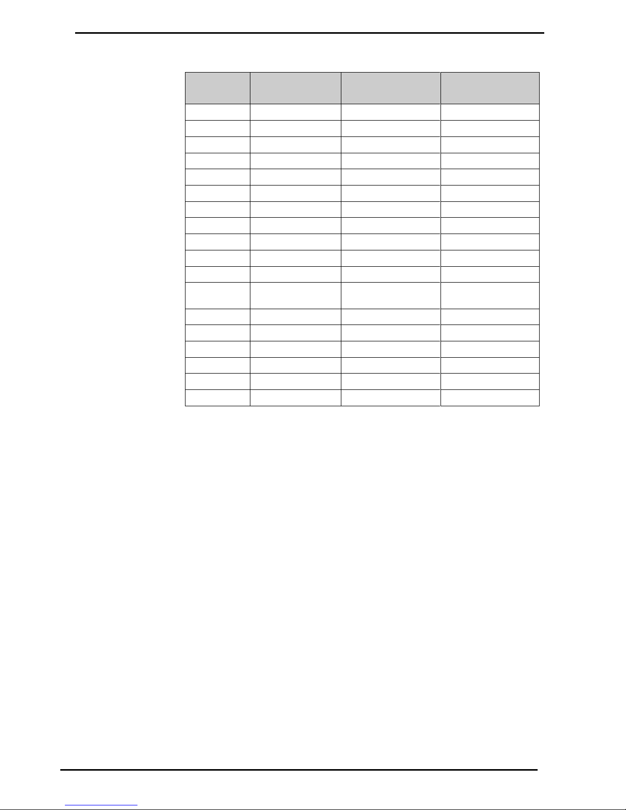
Pump Grade Maps
Grade
Number
Standard
Setup
BP Fuelcard
Setup (NZ)
Mobil Fuelcard
Setup (NZ)
1
Super
Diesel
Super
2
Unleaded
Super
Unleaded
3
Diesel
Oil 1
Diesel
4
PULP
Oil 2
CNG
5
LPG
T/Wash
LPG 6 Oil
C/Park
Oil 7 Kerosene
LPG
Kerosene
8
Avgas
Unleaded
Avgas
9
Jet A1
W/Bridge
Jet A1
10
Water
Oil 3
Water
11
CNG
Avgas
(not used)
12
MPD (Multiproduct)
Jet A1
Multi-product
13
Oil 1
Multi-product
Oil 1
14
Oil 2
Oil 4
Avgas
15
Oil 3
Oil 5
Jet A1
16
Oil 4
N/A
N/A
21
Receipt
Receipt
Receipt
22
Auth.
Auth.
Auth.
A receipt station (grade 21) has a cardreader with which the holder of a validated
card may request a receipt for a transaction carried out on any pump.
An authorisation station (grade 22) has a cardreader that enables the holder of a
validated card to select and use a pump. This is typically used when non-Compac
pumps are installed. An optional receipt printer may be attached to the authorisation
station.
Page 45
Main Menu Options
Option #4 SYSTEM
Compac Industries Ltd.
Page 45
www.compac.co.nz
Option #4 SYSTEM
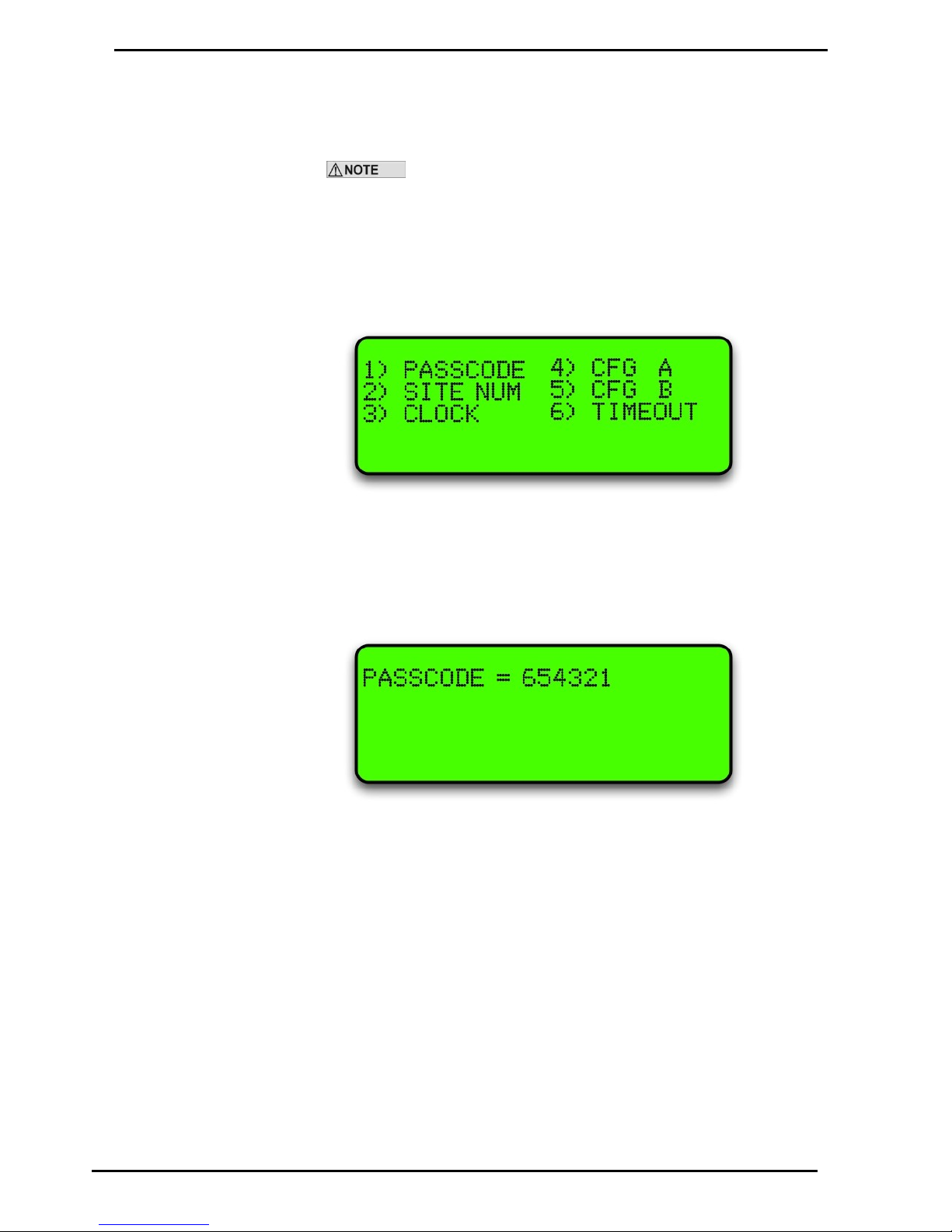
To set up a system the following parameters have to be set:
The Passcode and Site number have to be set up to enable Netbase
to dial into it.
The password and site number have to be set on site as they cannot be changed
remotely by Netbase
The Compac factory Passcode on new equipment is 654321.
The system screen looks like this:
Passcode
The factory set passcode 654321 can be changed using the "PASSCODE" option in
the Systems menu. Passcodes can be from 1 to 6 digits long.
If you want to change the passcode, enter it and press Enter.
Make sure you have recorded the new passcode as you will be locked out if you
forget it and the memory will have to be erased to reset it.
The following table describes the process.
Page 46
Option #4 SYSTEM
Main Menu Options
Compac Industries Ltd.
Page 46
www.compac.co.nz
Keyboard Entry
Result on Display
Operation
Enter Passcode
<ENTER>
Main Menu is displayed
<4>
System menu is displayed
<1>
PASSCODE = XXXXXX
(flashes)
Change Passcode
Type in new
passcode
PASSCODE = XXXXXX (still
flashes)
<ENTER>
Returns to System menu
Site Number
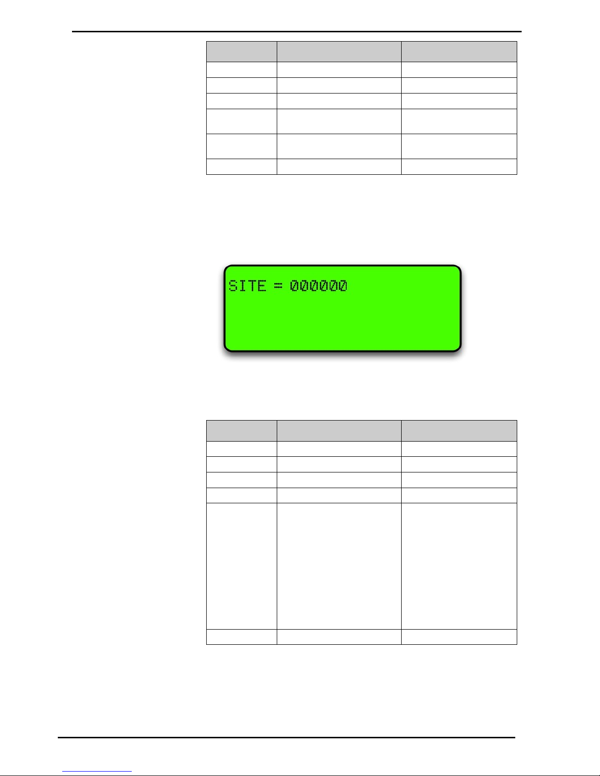
The site number is set by using the "SITE NUM" option in the Systems menu
If you want to set the site number, enter it and press Enter.
The following table describes the process.
Keyboard Entry
Result on Display
Operation
Enter Passcode
<ENTER>
Main Menu is displayed
<4>
System menu is displayed
<2>
SITE = XXXXXX (flashes)
Change Site Number
Type in site
number
(Factory set Site
number is #1
which can be
left if unit is not
part of a
Network. If part
of a Network,
consult the
Network
Supervisor.)
SITE = XXXXXX (still flashes)
<ENTER>
Returns to System menu
Page 47
Main Menu Options
Option #4 SYSTEM
Compac Industries Ltd.
Page 47
www.compac.co.nz
Setting the Clock
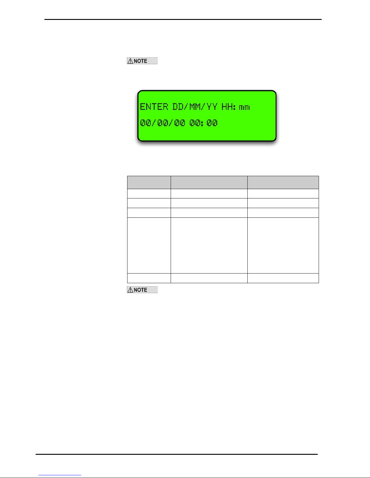
The setting of the clock is very important, as transactions are stored in chronological
order. The clock will need to be changed to compensate for Daylight Saving time.
If the clock setting is found to be wrong, upload transactions before
setting the clock correctly to ensure that transactions are picked up in the correct
order
To set the clock follow this procedure carefully as changing the wrong numbers may
disable the system < > means push that key.
Keyboard Entry
Result on Display
Operation
Enter Passcode
<ENTER>
Main menu is displayed
<4>
System menu is displayed
<3> ENTER DD/MM/YY HH:mm
DD = day
MM = month
YY = year (20YY)
HH = hour (in 24hr time)
mm = minutes
Set Date and Time
<ENTER>
Returns to system menu
The clock setting is not shown on the display. To check the clock
setting is correct, do a zero dollar transaction and check the time/date data on the
receipt.
Page 48
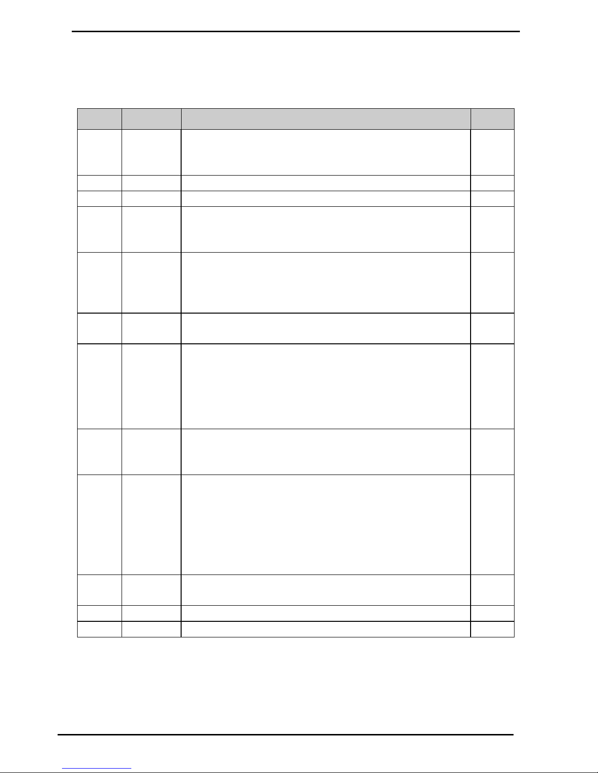
Option #4 SYSTEM
Main Menu Options
Compac Industries Ltd.
Page 48
www.compac.co.nz
Configuration "A" Settings
The configuration "A" is a 12 digit code that configures the unit for each application.
This is usually set at the factory. Only change the configuration settings if you are
sure that all information is backed up and that you are aware of any consequences.
Digit
Operation
Options
Display
1
Controller
Type
3 - Driveway Card Acceptor (DCA / ComFutra Default / Card King )
4 - Enable HID reader (Clock&Data)
5 - Enable HID reader (26bit Wiegand)
2
Unused
0- Default
3 Unused
0- Default
4
Receipt
Option
0 - Default
5 - Does not display NO RECEIPT in DCA mode if no receipt printer fitted
PR2
5
Unused
0- Default
6
Card File
0 - Default
5 - Big Hot Card file
7
User ID option
0 - No PIN. Note: Encoding on the card can activate a prompt for PIN
1 - Prompts for Employee number
2 - Prompts for Fleet number
4 – Prompts to "Enter Pin" and then forced User ID. If the wrong pin is
entered it will display "invalid Card"
6 - Prompts for Vehicle number
UIP
8
Odometer
prompt
0 - No odometer. Note: Encoding on the card can prompt for odo
1 - Load Odo/Engine Hours
ODO
9
Card type
0 - Cards not requiring specific configuration
2 - Mobilcard
4 - Prompts for Employee Number (Card number used as Employee
Number)
6 - Air BP card
7 - Shellcard
9 -Vehicle Number Authorisation (Prompts for vehicle number)
ABP
10
Validation
option
2 - Limited Validation - Cards
3 - Extended validation - Cards
LVC
EVC
11
Unused
0 - Default
12
Track
2 - Track 2
T2
Page 49

Main Menu Options
Option #4 SYSTEM
Compac Industries Ltd.
Page 49
www.compac.co.nz
Changing the "A" Settings
This is changed using the keypad and display. Follow this procedure carefully as
changing the wrong numbers may disable the system. < > means push that key.
Keyboard Entry
Result on Display
Operation
Enter Passcode
<ENTER>
Main Menu is displayed
<4>
System menu is displayed
<4>
CFG A = XXXXXXXXXXXX
(flashes)
was XXXXXXXXXXXX
Set Configuration A
Edit 12 digit
number
CFG A = XXXXXXXXXXXX (
still flashes)
was XXXXXXXXXXXX
<ENTER>
Returns to System menu
Page 50
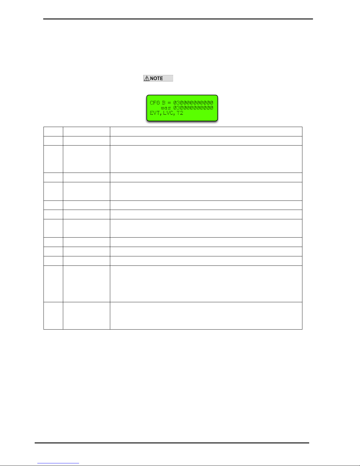
Option #4 SYSTEM
Main Menu Options
Compac Industries Ltd.
Page 50
www.compac.co.nz
Communicator Configuration code B (CFG B)
The Configuration Code B options available may depend on the software
version. Refer to the following charts for options.
For credit card units refer Credit Card Units "B" Settings (see page 52)
Not all options shown may be available on your unit. If
unsure, please refer to the Helpdesk for more information.
Digit
Operation
Options
1
Unused
0
2
Printer
0 - Seiko drop box printer
2 - T2460 printer with cutter
3 - T2460 printer without cutter
3
Unused
0
4
CIM-less DCA
0 – DCA with CIM (early version card reader) Default Setting
1 – DCA with PINPad and Magtek TTL card-reader (changes receipt cut length)
5
Unused
0 6 Shift Reports
0
7
Audit Trial
0 - LX300 (7bit; Even parity; 1 stop bit; 9600baud)
1 - LX300+ (8bit; No parity; 1 stop bit; 9600baud)
8
Netpac reports
0
9
Tax
0
10
Accountpac
0
11
Override
0 - Default
1 - Ignore expiry date
2 - Ignore Grade Restriction
3 - Ignore both Expiry date and Grade restriction (software dependent)
12
OIML options
1 - OIML checking
2 - OIML checking and Video Primary display (COMMANDER)
2- UPS checking (DCA)
Page 51
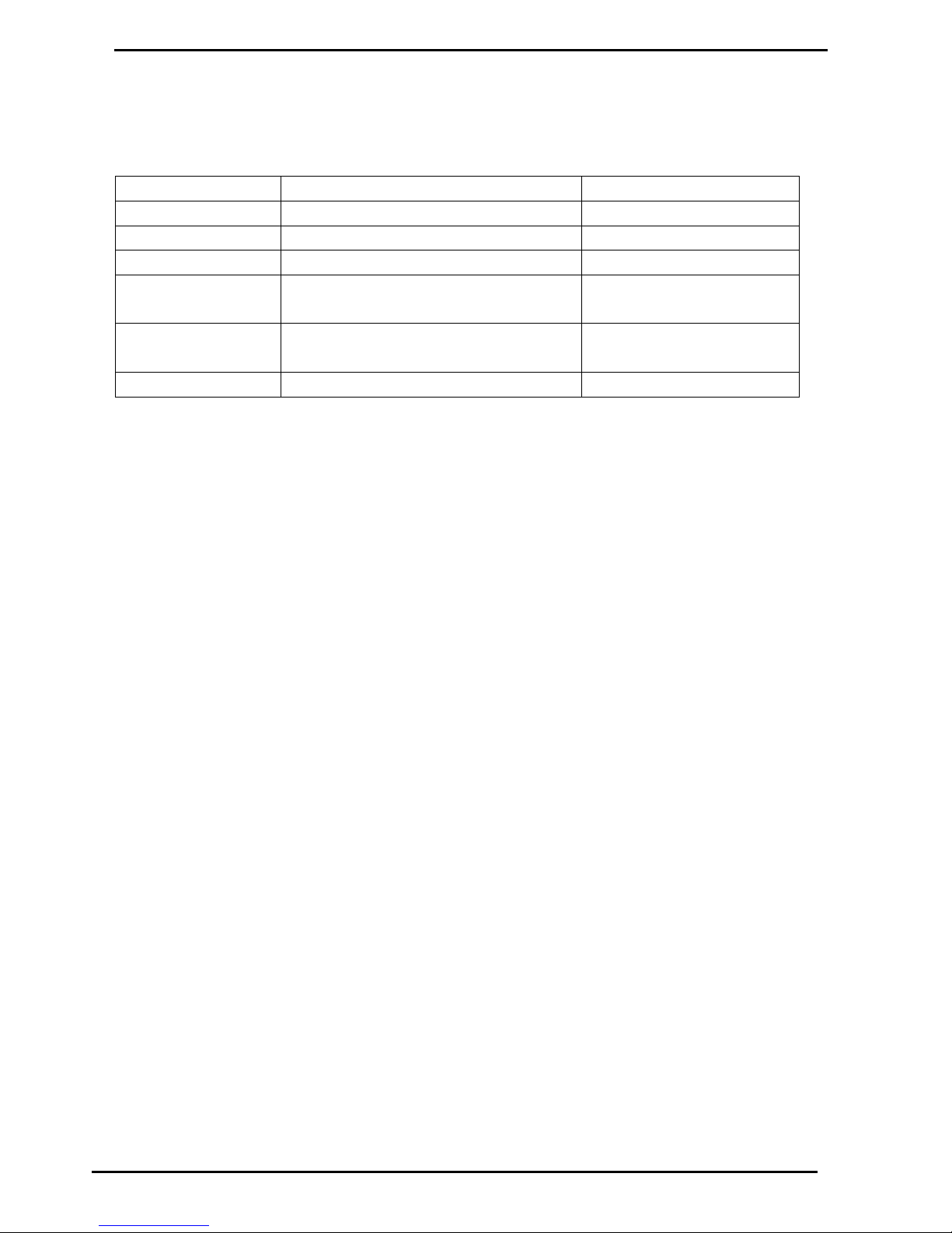
Main Menu Options
Option #4 SYSTEM
Compac Industries Ltd.
Page 51
www.compac.co.nz
To change the "B" settings
This is changed on the keypad and display on the unit. Follow this
procedure carefully as changing the wrong numbers may disable the
system < > means push that key.
Keyboard Entry
Result on Display
Operation
Enter Passcode
<ENTER>
Main Menu is displayed
<4>
System menu is displayed
<5>
CFG B = XXXXXXXXXXXX (flashes)
was XXXXXXXXXXXX
Set Configuration B
Type in 12 digit number
CFG B = XXXXXXXXXXXX ( still flashes)
was XXXXXXXXXXXX
<ENTER>
Returns to System menu
Page 52

Option #4 SYSTEM
Main Menu Options
Compac Industries Ltd.
Page 52
www.compac.co.nz
Credit Card Units "B" Settings
The Compac credit card capable units can be set up with a variety of credit
card authorisation options using the "B" settings. The settings differ from the
normal "B" options fitted to the standard unit.
Digit
Operation
Options
1
Unused
0
2
Printer
0 - Seiko drop box printer
2 - T2460 printer with cutter
3 - T2460 printer without cutter
3
Transactions
0 – Default, transactions must be deleted before over writing.
6 – Transactions are automatically deleted.
4*
CC DCA
0 – Default
1 – $5 Over Authorisation
5**
CC DCA
0 – Standard, no CVC2 Prompt, no authorisation retry
1 – CVC2 Prompt, no authorisation retry
2 – Authorisation retry, no CVC2 prompt
3 – CVC2 Prompt and authorisation retry
4 – Selectable authorisation range
5 – CVC2 + Enter authorisation
6 – Enter user selected authorisation
6
Unused
0 7 Unused
0
8
Unused
0
9
Unused
0
10
Unused
0
11
Override
0 - Default
1 - Ignore expiry date
2 - Ignore Grade Restriction
3 - Ignore both Expiry date and Grade restriction
12
OIML options
0 - No OIML checking.
2 - UPS checking (DCA)
Page 53

Main Menu Options
Option #4 SYSTEM
Compac Industries Ltd.
Page 53
www.compac.co.nz
* When option 1 is selected, the unit applies for an authorisation amount
$5.00 more than selected. This is to prevent pumps over running and
dispensing more than the amount authorised which can create conflict at the
authorising bank.
** These options can be set to offer a variety of authorisation amounts and
whether a CVC2 (back of card security code) entry is required.
To change the "B" settings
This is changed on the keypad and display on the unit. Follow this procedure
carefully as changing the wrong numbers may disable the system. < > means
push that key.
Keyboard Entry
Result on Display
Operation
Enter Passcode
<ENTER>
Main Menu is displayed
<4>
System menu is displayed
<5>
CFG B = XXXXXXXXXXXX (flashes)
was XXXXXXXXXXXX
Set Configuration B
Type in 12 digit number
CFG B = XXXXXXXXXXXX ( still flashes)
was XXXXXXXXXXXX
<ENTER>
Returns to System menu
Page 54
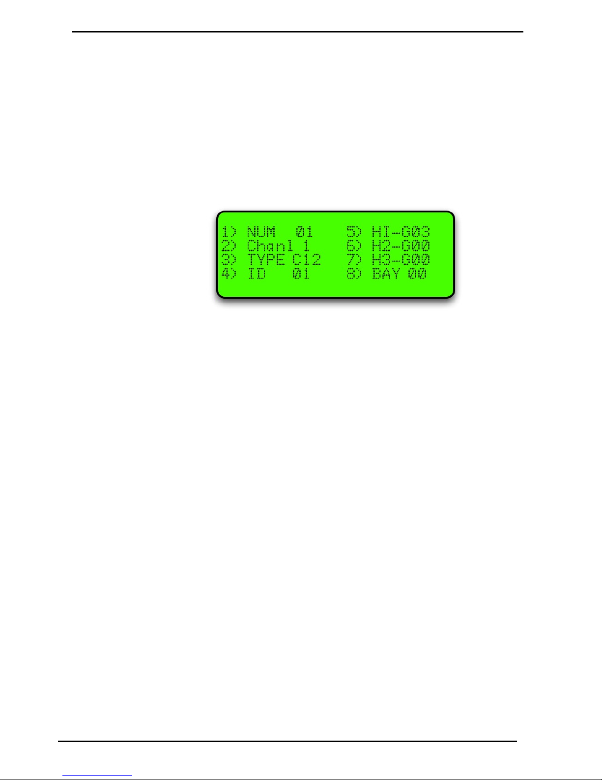
Option #5 PUMPS
Main Menu Options
Compac Industries Ltd.
Page 54
www.compac.co.nz
Option #5 PUMPS
To set up a pump each of the following parameters have to be set:
(There is also an option for Bay Number which is only used in special applications.)
Use the YES and NO keys to select to the pump number
If a Dual pump on Gilbarco comms the pump number on side B should be lower
than the pump number on side A. e.g. A = 2, B = 1
For Compac comms the side A pump number is usually the larger number but will
work either way round.
Figure 13: Typical settings for hose 1
Page 55

Main Menu Options
Option #5 PUMPS
Compac Industries Ltd.
Page 55
www.compac.co.nz
Comms Channel
The comms channel will usually be set at the factory depending on the site setup.
Channel 1 or Channel 2 are the available options.
Number
Operation
1
Channel 1 pump comms e.g. via 2 pin 'PUMP COMMS 1' on rear panel
(for Compac pumps) Can also be setup for RS232 comms via Port #5
2
Channel 2 pump comms used for the following:
(a) Gilbarco comms I/F via TTL Port #4
(b) Email comms I/F via TTL Port #4
(c) 2nd Comms channel (pumps 17 to 32) 'PUMP COMMS 2' on rear
panel via TTL Port #4
(d) Tankgauging I/F (e.g. VeederRoot, Diptronic, Franklin )
0
No comms -This will disable comms to a pump even if all the other
parameters are set correctly
Comms Type
For Compac pumps enter <2>
For Gilbarco pumps enter <6> (goes to sub-menu to select Gilbarco type)
Important note when setting up Gilbarco pumps
Electroline pumps may need to be setup as Hilines or vice-versa. If experiencing
difficulties getting Gilbarco pumps to work on a Communicator, try changing the
type. After changing the type, the Communicator MUST be re-powered.
For Email pumps enter <7> or <8> (depending on type of pump)
If in doubt, contact your Compac agent for the correct settings.
Pump ID
For simplicity, this is usually set to the same number as the Pump number. The
Controller looks for a pump with a pump number that matches the ID number
Eg. Pump number 01 set up in controller but ID set to 05
Controller looks for a pump with pump # 05
Page 56
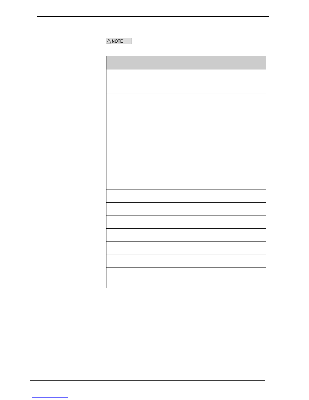
Option #5 PUMPS
Main Menu Options
Compac Industries Ltd.
Page 56
www.compac.co.nz
Product Group Number
Options 1,4,5,6 & 7 require the <ENTER> key to be pressed to save
the number you have entered (the cursor flashes). Options 2 & 3 are saved as you
type in the number (the cursor does not flash).
Keyboard Entry
Result on Display
Operation
Enter Passcode *
<ENTER>
Main Menu is displayed
<5>
Pump Menu is displayed
<1>
'Num xx' flashes
Set Pump Number
Type in pump
number
'Num xx' still flashes
<ENTER>
'Num xx' stops flashing (number
saved)
<2> **
Scrolls between 1,2 & 0 each time
<2> pressed
Set pump channel
number
<3> ***
Comms Type Menu is displayed
Set pump comms type
<4>
'ID' flashes
Set ID Number
Type in ID
number
'ID' still flashes
<ENTER>
'ID stops flashing (number saved)
<5>
'H1-G01' flashes
Set hose 1 Product
group
Type in Number
'H1-G01' still flashes
(Single, Dual, 4 & 6
Hose Multi)
<ENTER>
'H1-G01' stops flashing (number
saved)
<6>
'H1-G02' flashes
Set hose 2 Product
group
Type in Number
'H1-G02' still flashes
(Dual, 4 & 6 Hose Multi
only)
<ENTER>
'H1-G02' stops flashing (number
saved)
<7>
'H1-G03' flashes
Set hose 1 Product
group
Type in Number
'H1-G03' still flashes
(6 Hose Multi only)
<ENTER>
'H1-G03' stops flashing (number
saved)
Refer to Tanks/Pumps/Groups (see page 68) first for a detailed explanation on how
to set up groups.
Page 57

Main Menu Options
Comms Options
Compac Industries Ltd.
Page 57
www.compac.co.nz
Comms Options
The unit can support two protocols at once out of the following:
Compac/PEC
Gilbarco
Email
For Email and Gilbarco comms, interface boards are required
These can be connected to either Port 4 (TTL) or Port 5 (RS232) although if only
one interface board is used, it is normally connected to Port 4 (TTL)
If BOTH Email and Gilbarco comms are required, then Compac comms are
unavailable.
Comms Channels
The Communicator has two comms channels (Compac or Gilbarco and Email).
Usually Compac pump comms are assigned to channel 1 and the other comms
assigned to channel 2.
Channel 1 can be either Current loop or RS232 (to either an Email or Gilbarco I/F
board)
Channel 2 is TTL (to either an Email or Gilbarco I/F board)
This table shows which combinations of protocols are used on the two channels
Channel 1
(Current Loop)
Channel 2
(Current Loop)
Channel 1
RS232
(Port 5)
Channel 2
TTL (Port
4)
Dip-Switch
1
Dip-Switch
2
Dip-Switch
6
Dip-Switch
7
Compac/PEC
ON
OFF
OFF
OFF
Compac/PEC
Compac/PEC
ON
OFF
ON
ON
Compac/PEC
Gilbarco
ON
OFF
OFF
OFF
Compac/PEC
Email
ON
OFF
OFF
OFF
Email
Gilbarco
OFF
ON
OFF
OFF
Gilbarco
Email
OFF
ON
OFF
OFF
Page 58

Comms Options
Main Menu Options
Compac Industries Ltd.
Page 58
www.compac.co.nz
Comms Dip-switches
The comms dip-switch is an 8 way switch but normally only numbers 1 and 2 are
used. These two switches direct Channel 1 comms to either Current Loop or RS232
(Port 5).
Only one of these switches must be on. The factory default setting is 1 ON 2-8 OFF.
Where more than 16 pumps are controlled, the Current Loop Channel 2 can be
added by using Dip switches 6 and 7.
Second Current Loop Comms Channel
There are two current loop comms channels (for Compac Pumps) on the Com FMS
board. If a fault occurs on Current Loop Channel 1 and Current Loop Channel 2 is
not being used then the channels can be switched over.
To connect Compac pumps to the second current loop comms channel
1. Change the comms channel in the pump setup to Channel 2. Refer to Pumps
(see page 69)
2. Move the wires on the 2 core comms cable on the “Current Loop” plug to the
second position in from each end. Refer Comm FMS Board Replacement (see
page 92) for detail.
3. Change the dipswitches to the following settings:
1
X
2 X 3 X 4
X
5
X
6
ON
7
ON
8
X
Page 59
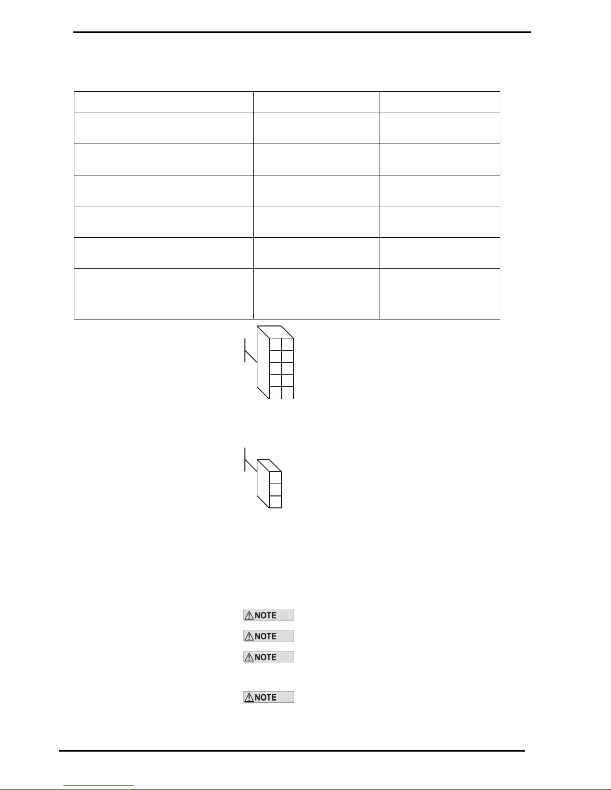
Main Menu Options
Comms Options
Compac Industries Ltd.
Page 59
www.compac.co.nz
Email Comms
Status of LEDs on Communicator board when connected to Port #4
Red Rx
Green Tx
Email board unplugged from Communicator
board
Off
Flashes rapidly
Email board plugged in but pump not
connected
Flashes
Flashes in time with Rx
Email board plugged in but pump set up for
Compac comms
Off
Flashes rapidly
Email board plugged in but pump set up for
wrong channel
Off
Off
Email board plugged in but pump ID
incorrect
Flashes
Flashes in time with Rx
Email board plugged in and operating
correctly
Flashes very rapidly and is
much brighter that Tx
almost looks like its stuck
on
Flashes very rapidly
1
2
3
4
5
6
7
8
9
10
1-
2- Brown
3- Blue
4-
5- Red
6- Green
7-
89- Black
10- White
Cable between Port #4 and J4 on Email board
Note the connections are the same both ends
J1 Comms plug on Email board
1
2
3
1- White
2- Blue
3- Shield
Dip Switch SW1
The Yellow, Orange Red and Brown switches should be closest to the
centre of the board
i.e. A,B,C & D visible
Only issue C Communicator boards support Email protocol
Multi hose Email pumps are not supported.
The Shield and Blue wires should not be swapped over. If
they are the system may appear to work but cause intermittent comms
problems.
Take great care line up the locking tabs on the green plugs
correctly as reversal of these will damage the Email board.
Page 60
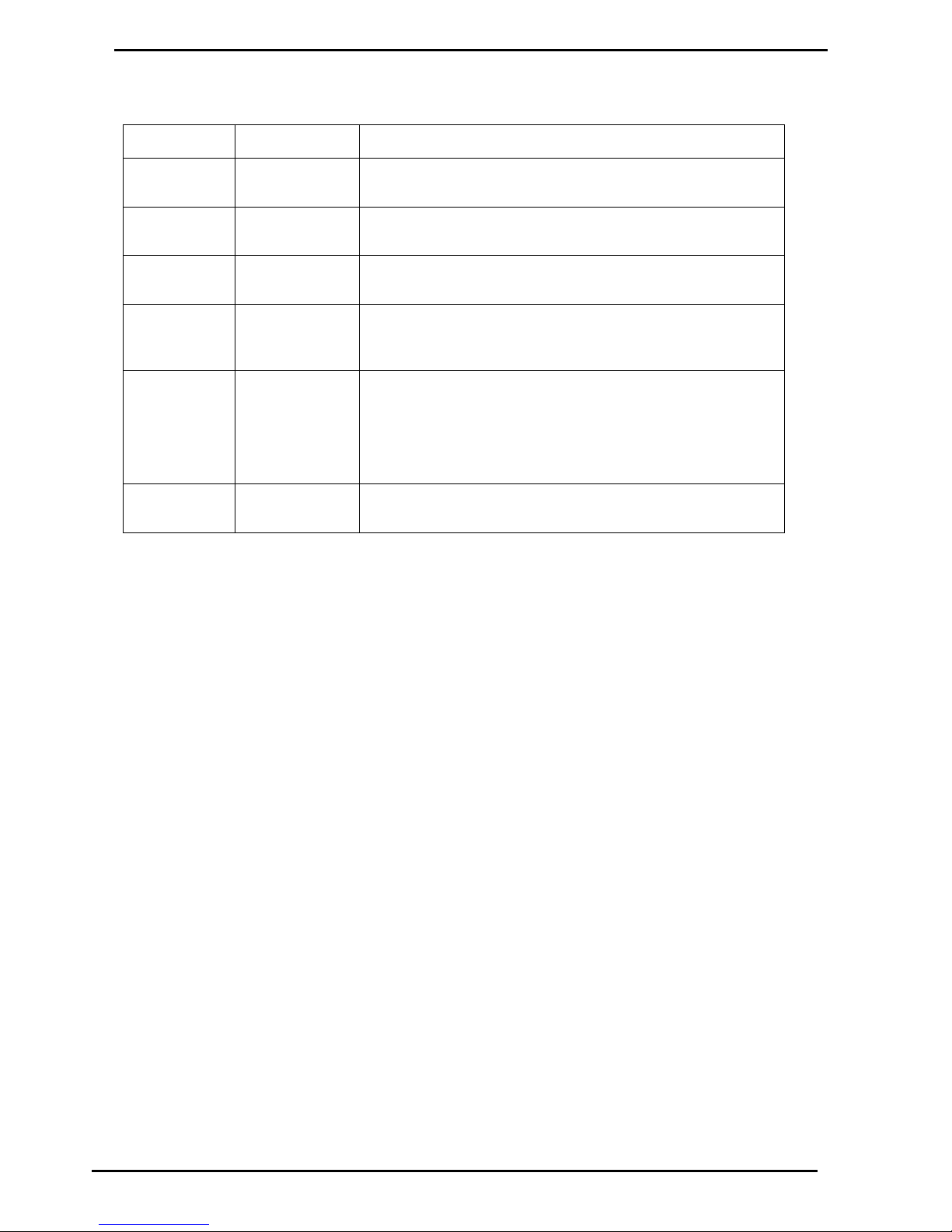
Comms Options
Main Menu Options
Compac Industries Ltd.
Page 60
www.compac.co.nz
Gilbarco Comms
Status of the Red and Green LEDs on Port #4
Red LED
Green LED
Flashes rapidly
and unevenly
Flashes rapidly
and unevenly
Pump communicating normally
OFF
Flashes rapidly
Comms channel set up for Channel 2 but Gilbarco board not
connected
ON
OFF
Gilbarco board connected but Comms channel not set up for Channel
2
ON
Flashes rapidly
(dimly)
Gilbarco board connected, Comms channel set up for Channel 2 but
no pump connected
Flashes slowly
(and dimly)
Flashes slowly
(and dimly)
(simultaneously
with Red LED)
Comms channel set up for Channel 2 but short on Gilbarco pump
comms or pump comms wires reversed.
Flashes rapidly
and unevenly
Flashes rapidly
and unevenly
Pump appears to be communicating but does not work when nozzle is
lifted - Pump is set up as a Hi-line instead of an Electroline
A DC voltage of approx 2 to 5V can be measured across the Gilbarco
comms to establish whether a pump is connected.
Page 61
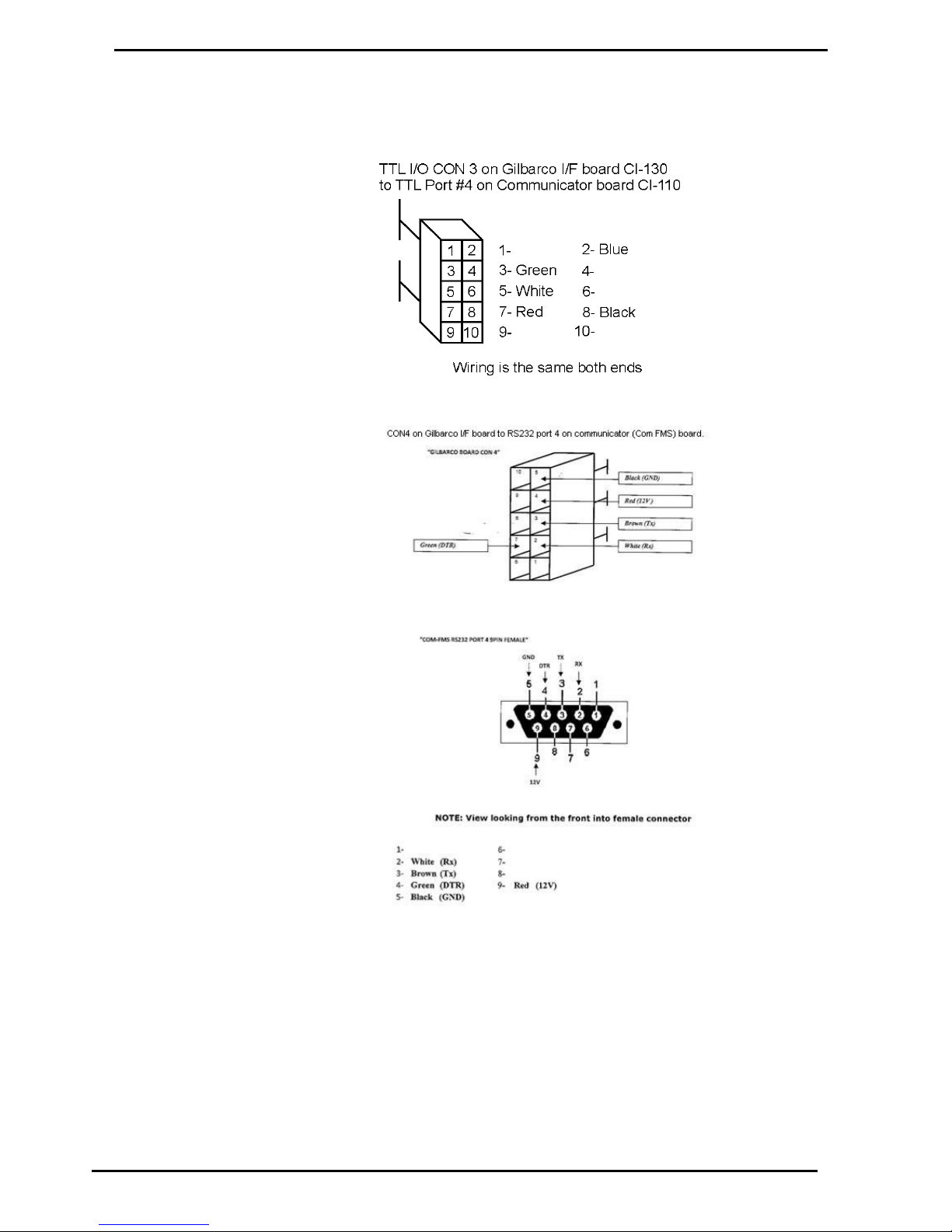
Main Menu Options
Comms Options
Compac Industries Ltd.
Page 61
www.compac.co.nz
Gilbarco Wiring
Wiring can either be from CON3 on the Gilbarco I/F board to TTL port 4 on
the communicator board (channel 2 only) or from CON4 to RS232 port 4 on
the communicator board. Examples are shown below:
Page 62
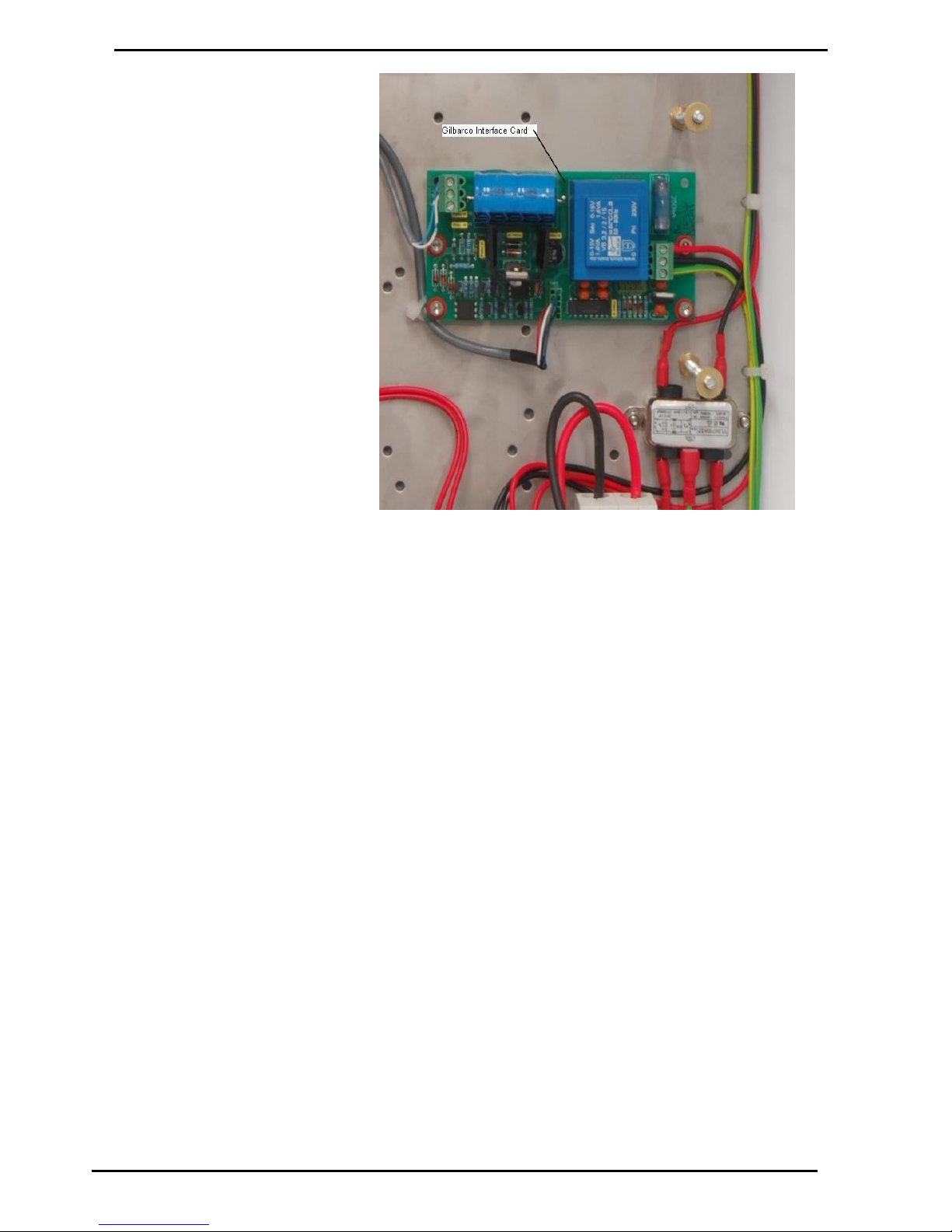
Comms Options
Main Menu Options
Compac Industries Ltd.
Page 62
www.compac.co.nz
Figure 14: Gilbarco Interface Card with TTL connection
Page 63
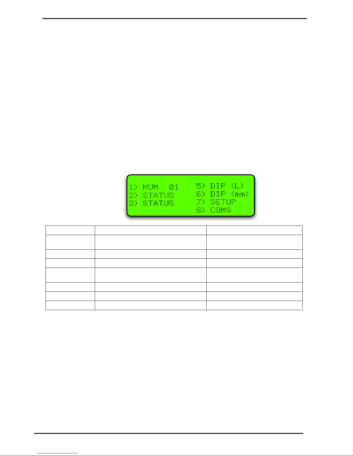
Main Menu Options
Option #6 TANKS
Compac Industries Ltd.
Page 63
www.compac.co.nz
Option #6 TANKS
This is usually set at the factory. The only time it might need to be changed is if a
tank gauge is added or if the tank gauge is changed.
The following Tank interface options are available:
1. Theoretical (THEO)
2. VeederRoot (VDDR or FRNK)
3. Diptronic (DIPT)
4. Franklin (FRNK)
5. Colibri (FRNK)
The following instructions refer to the Franklin setup. Slightly different screens may
appear if other tank options are selected.
The Franklin setup displays the information sent from the tank gauging unit and also
works for Veeder Root TLS2 and Colibri units. Other setups require a strapping table
to be entered.
Select Tanks from the main menu.
Menu Option
Function
Operation
1. No XX
Tank number
Scroll up and down with NO and YES to
select tank
2. Status
Displays theoretical Capacity and Volume
3. Status
Displays tank temperature (Franklin option only)
4. Delivery
Enter in delivery of product
Type in delivery volume (Theoretical
only)
5. Dip (L)
Enter in dipped volume (in litres)
Type in new volume (Theoretical only)
7. Setup
Sets up alarms, capacity and Product Group.
Refer to Tank setup table
8. COMMS
Sets up comms type
Refer to Tank Comms table
Tank number is usually set as 1. If there are more tanks, use the YES and NO keys
to select to the tank number you want to set up.
Page 64
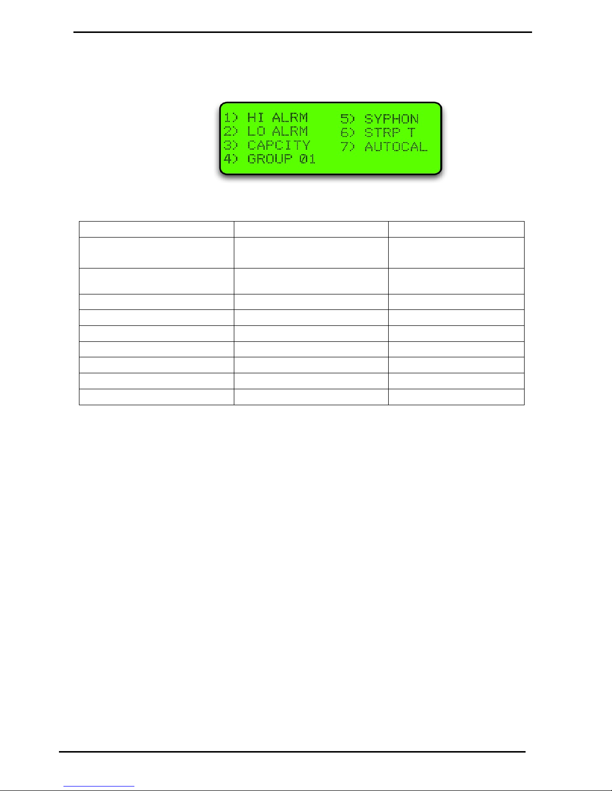
Option #6 TANKS
Main Menu Options
Compac Industries Ltd.
Page 64
www.compac.co.nz
Tank Setup Table
Select Setup from the Tanks menu and the following screen will open.
For the Franklin and Colibri units, only the capacity and group (if using groups) need
to be entered.
Keyboard Entry
Result on Display
Operation
<7>
Capacity
Group 00
<3>
Capacity = XXXXXXXX
Set Tank capacity (NOT required
for Diptronic, Franklin or Colibri)
Type in capacity
<ENTER>
Returns to Setup menu
<4>
Cursor flashes
Set group
Type in product group number
<ENTER>
Cursor stops flashing
<CLEAR>
Returns to setup menu
<CLEAR>
Returns to main menu
For the units setup with Franklin comms, return to the main tanks menu and select
(2) Status. The tank gauge readings should be displayed. Select (3) Status and the
tank temperature should be displayed.
Depending on tank gauging and software installed, other options may or may not be
available.
Page 65
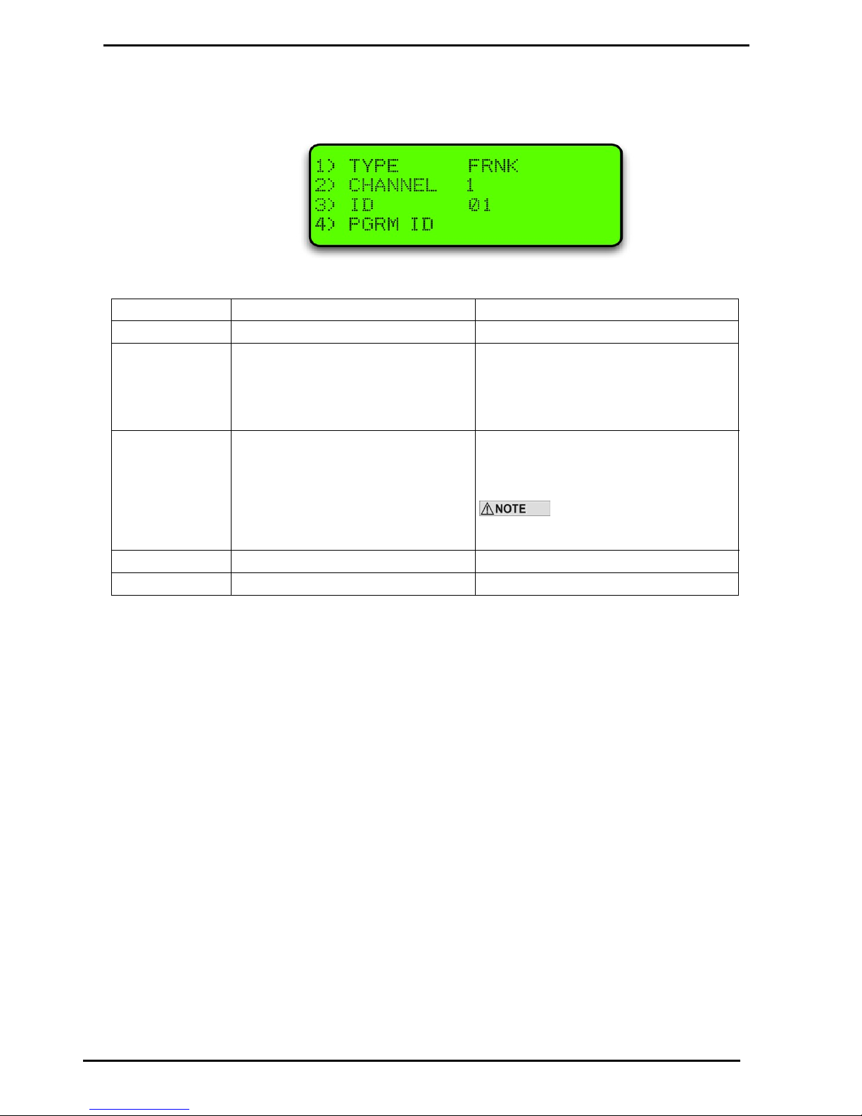
Main Menu Options
Option #6 TANKS
Compac Industries Ltd.
Page 65
www.compac.co.nz
Tank Comms Table
Select Comms from the menu and the following screen will open.
Pressing 1 will scroll through the comms options.
Keyboard Entry
Result on Display
Operation
<8>
<1>
THEO \ FRNK \ VDDR \ DIPT
2. CHANNEL X
3. ID XX
4. PGRM ID
Scroll through by repeatedly pressing <1> to
select comms type
<2> (NOT shown in
THEO Mode)
2. CHANNEL 0, 1 or 2
Scroll through by repeatedly pressing <2> to
select Channel number 2
Tank Gauging normally works on
Channel 2 (Selecting Channel 0 turns the tank
off)
<3>
ID
Same as tank number
<4>
PGRM ID
Not used
Depending on tank gauging and software installed, other options may or may not be
available.
Tank Gauging Troubleshooting
To check that the tank gauging unit is communicating with the FMS board,
look at the following LEDs:
Page 66
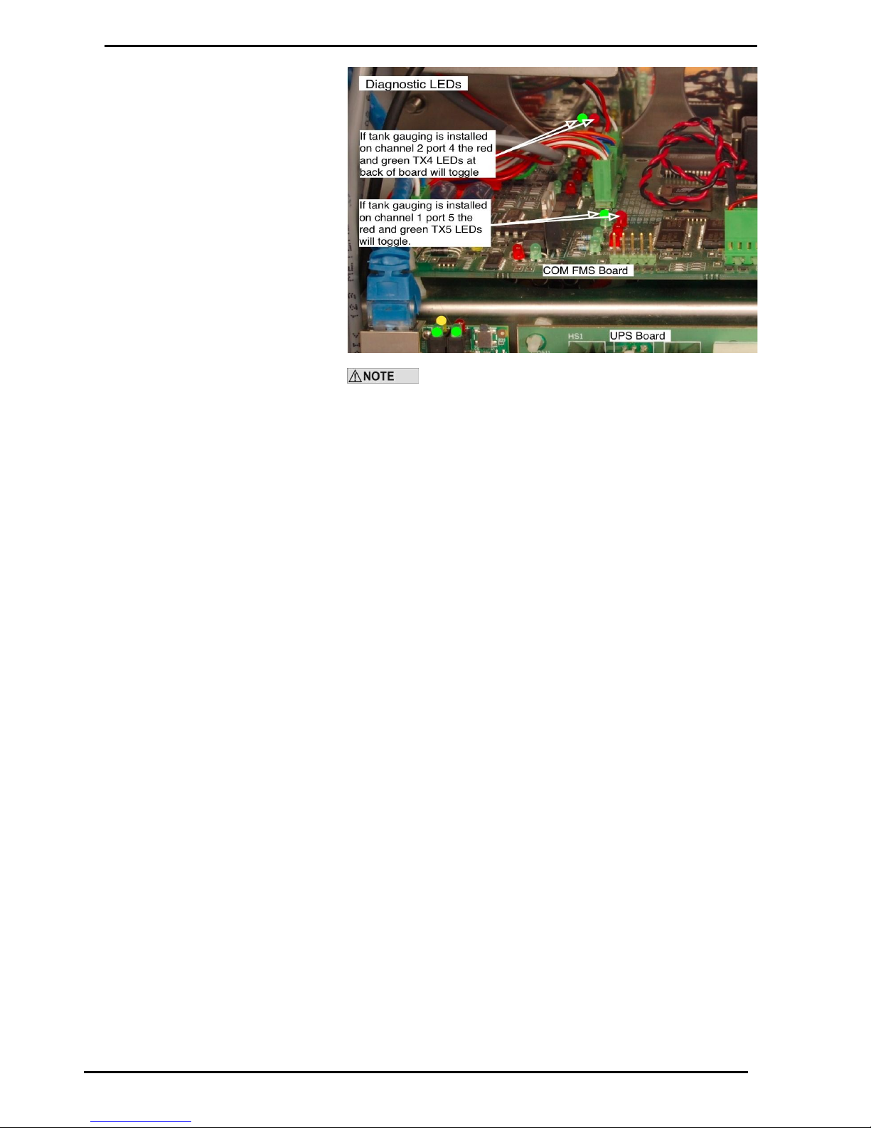
Option #6 TANKS
Main Menu Options
Compac Industries Ltd.
Page 66
www.compac.co.nz
Most tank gauging is set up on Port 4 Channel 2. The
exception is for units controlling Gilbarco pumps.
If the green Tx LED is not flashing, check the settings in the FMS board.
If the red Rx LED is not flashing, check the settings in the tank gauge unit.
If all settings are correct, check for a cable fault by shorting the Rx and Tx
wires together at the tank gauge end. The LEDs should flash together. If
not, there is a break in the cable.
The wiring of the tank gauging cable may change for different models. If
you are changing tank gauge units, you may need to swap the Tx and Rx
wires to get it to work.
Page 67
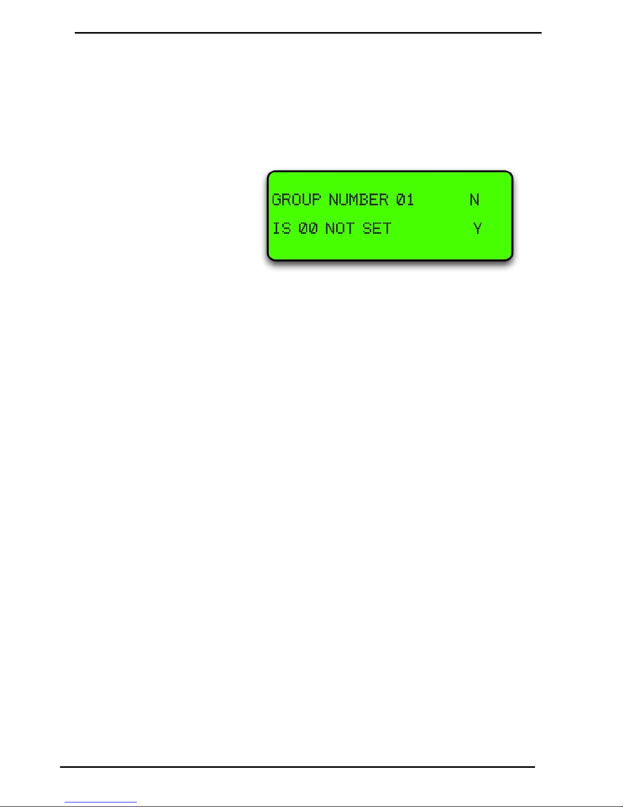
Main Menu Options
Option #7 PRODUCT GROUPS and GRADES
Compac Industries Ltd.
Page 67
www.compac.co.nz
Option #7 PRODUCT GROUPS and GRADES
The allocation of tanks and pumps for fuel dispensing involves the use of
groups. (If you are used to the concept of grades, you can think of groups
as the equivalent of grades.) The group is a controller protocol that aids
product reconciliation and also enables fuel dispensing to be tailored to suit
different local conditions. The group is like a junction box through which
tanks, pumps, devices and products are assigned.
Page 68
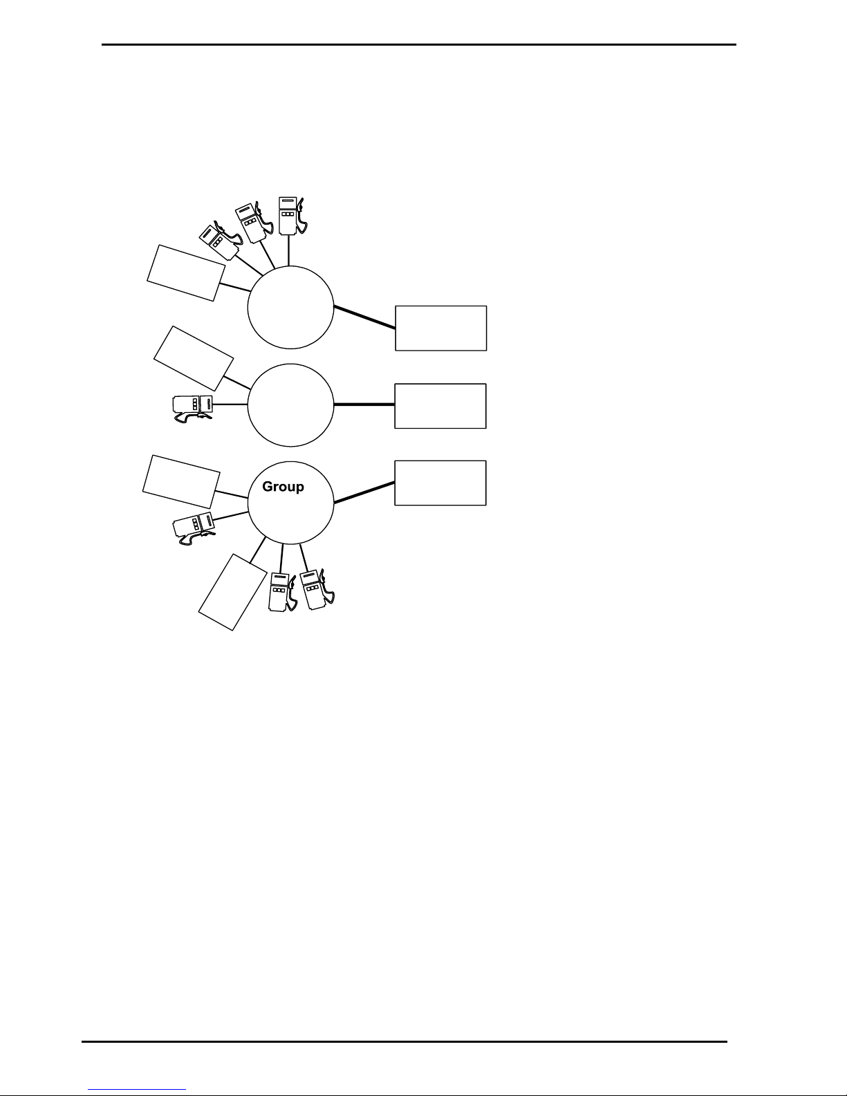
Tanks/Pumps/Groups
Main Menu Options
Compac Industries Ltd.
Page 68
www.compac.co.nz
Tanks/Pumps/Groups
Concept
Function
2
Unleade
d
Function
3
Supe
r
Function
1
LPG
T
a
n
k
#
1
1
U
n
l
e
a
d
e
d
Group
1
dedicated
to
Function
2
S
u
p
e
r
L
P
G
U
n
l
e
a
d
e
d
Unleaded
A group is set to one function - e.g. a product with all the tanks, pumps, and devices needed
to perform that function.
Groups
A function is an interface between the
installation and client - e.g. dispensing
a product.
Functions 1 - 16 are products,
Function 21 is the receipt station,
Function 22 is the authorisation station.
Functions
Each tank must be individually set to
a group.
A tank can only be set to one group.
However, more than one tank
may be set to the same group.
Tanks
Each pump must be individually set to
a group.
A pump can only be set to one group.
However, more than one pump
may be set to the same group.
Pumps
Each hose on an M.P.D. must be individually set to a group.
E.g. in the example shown, an M.P.D. dispensing
LPG and Super would have its LPG hose(s) set to
Group 2 and its Super hose(s) set to Group 3.
Multi-Product Dispensers
U
n
l
e
a
d
e
d
T
a
n
k
#
1
2
L
P
G
T
a
n
k
#
1
3
S
u
p
e
r
Group
2
dedicated
to
Function
1
3
dedicated
to
Function
3
T
a
n
k
#
1
4
S
u
p
e
r
S
u
p
e
r
S
u
p
e
r
Groups
The first stage in setting up is to marry the functions performed by the site to
groups that you create in the groups menu option. Each group is dedicated to
one grade or function.
In the 'Groups' menu option, first select a unique number for a group, then
select the number of the grade or function it is to be dedicated to. The group
numbers don't have to be in sequence and may be any numbers between 1
and 20.
For the grade/function map refer to Pump Grade maps (see page 44).
Page 69

Main Menu Options
Tanks/Pumps/Groups
Compac Industries Ltd.
Page 69
www.compac.co.nz
Tanks
Once the groups have been decided, the 'Tanks' menu option enables each
tank to be allocated to a group. A tank must be dedicated to one group; it
cannot be allocated to different groups. However, more than one tank may be
dedicated to the same group.
Select Tank
Each tank must be set up individually
Select Tank - Group
This option allows you to match the tank number to the appropriate group
number.
Pumps
The 'Pumps' menu option is where pumps are set up.
Select Pump
Each pump is set up individually.
Set Channel
0 - offline / not used.
1 - on board current loop 1 / external protocol converter.
2 - on board current loop 2 / internal protocol converter.
Set Type
C12 - Compac current loop pump comms, 1200 baud (NZ Standard).
C24 - Compac current loop pump comms, 2400 baud (Compac pumps only.
GC - Gilbarco Calcopac.
GEL - Gilbarco Electroline.
GHL - Gilbarco High line.
GMP - Gilbarco Multi product.
EME - Email Eclipse
EMV - Email Vision
Set ID
The number in the pump head. This must be unique per channel, per protocol.
Set hose – Group
Allocate different product hoses to different groups; for a single hose just set
H1.
Page 70

Setting Product Groups
Main Menu Options
Compac Industries Ltd.
Page 70
www.compac.co.nz
Setting Product Groups
Pumps are not directly assigned to a Product Grade
Each pump is assigned to a Product Group
Each Product Group is in turn assigned to a Product Grade
For simplicity, in the majority of applications the Product Group numbers
can mirror the Product Grade numbers according to the standard Grade
Map
The most common are:
Grade number
Product names as they appear
in the Communicator / Commander
Also referred to, or used for the
following products
1
Super
Premium, Premium Unleaded, 96, LRP
2
Unleaded
Unleaded 91 , 91, ULP
3
Diesel
4
PULP
Premium Unleaded Petrol
5
LPG 6
Oil 7
Kerosene
8
AVGAS
9
JET A1
This option simply assigns products to groups
Keyboard Entry
Result on Display
Operation
Enter Passcode
<ENTER>
Main Menu is displayed
<7>
1) Group # XX
2) IS XX Product (or NOT set)
Use N and Y keys to scroll
up or down the Groups
Select Group to assign product to
<2>
1) Group # XX
2) IS XX (flashes) Product (or NOT set)
Type in product number
Refer to Grade Map for
Product number
<ENTER>
2) IS (Selected Product name)
Use N and Y keys to scroll
up or down to select
another Group
Same as for previous Group
or <CLEAR>
Returns to Main menu
Page 71
Assigning Pump Numbers to Hoses
Compac Industries Ltd.
Page 71
www.compac.co.nz
Assigning Pump Numbers to Hoses
Pump numbers for each model
Model
Number of pump numbers to set up
Master Premier Laser Single
One
Master Premier Laser Dual
Two
Laser 4 hose Quad
Two
Legend 4 hose
Two
Legend 6 hose
One in each C4000
Order of pump numbers
Compac comms
The pump number for Side A is usually lower than Side B
Gilbarco comms
The pump number for Side A must be higher than Side B
Assigning Hoses to Product Groups
It is important to look at the Pump or Dispenser from the 'FRONT'
Remove the doors and a 'FRONT' sticker will be found on the hydraulic mounting
rail.
When looking at the front of the Pump/Dispenser, Hose 1-Side A is always on your
right (as per the following diagrams)
Page 72
Legend 4 Hose, 6 Hose and Laser 4 Hose Quad
Assigning Hoses to Product Groups
Compac Industries Ltd.
Page 72
www.compac.co.nz
Legend 4 Hose, 6 Hose and Laser 4 Hose Quad
The layout for Hose 1 and 2 is the same for 4 hose and 6 hose MPDs
On a 6 hose MPD, hose 3 is in the middle
As Hose 1 (side A) is opposite Hose 1 (side B) the product group will
be the same for both.
FRONT
Hose 4
Side B
Legend 4 Hose &
Laser 4 Hose Quad
Hose 1
Side A
Hose 2
Side A
Hose 3
Side B
Legend 6 Hose
Hose 3
Side B
Hose 1
Side B
Hose 2
Side B
Hose 2
Side A
Hose 3
Side A
Hose 1
Side A
FRONT
Page 73

Assigning Hoses to Product Groups
Compac Industries Ltd.
Page 73
www.compac.co.nz
Master, Premier and Laser (Single and Dual)
FRONT
Hose 1
Side B
Master Premier &
Laser (Single & Dual)
Hose 1
Side A
Page 74

Expiry Date
Cards
Compac Industries Ltd.
Page 74
www.compac.co.nz
Cards
Expiry Date
The expiry date on the card must be less than 10 years from today's date. If the date
is more than 10 years old, Expired Card will appear when the card is swiped. To
allow expired cards to be used you can use this procedure:
Change the second digit from the right in the 'B' configuration code to 1.
Overriding the Expiry Date
Enter the Passcode. If the Display on the unit reads “ENTER PASS CODE” type in
your 6 digit Passcode. (If you do not know the passcode, contact the Compac
Industries Help Desk. The default Password on new Communicator Controllers is
000000) Or, if the display reads PASS CARD, press the <NO> key. This will then
bring up “ENTER PASS CODE”. The main menu will then be displayed.
Press <4> (SYSTEM) The system sub menu will be displayed.
1. Press <5> (CFG B)
2. Display will read: CFG B = XXXXXXXXXXXX (12 digit binary number) Was
XXXXXXXXXXXX
3. Take careful note of the existing CFG B number
4. Type in a new 12 digit number with the 11th digit from the left = 1 for example
XXXXXXXXXX1X. This will overwrite the existing number in the top line but you
will still be able to still view the old number in the bottom line as you type in the
new number. for example Old CFG B was 000000100000 new CFG B with
expiry date override = 000000100010
5. Press <ENTER>
6. Press <CLEAR> twice to return to Main screen.
Although it is possible to put the clock back in the Communicator to
less than 10 years from the expiry date of the card to make it work this is not
recommended as date range reporting functionality is affected and some
transactions may not be able to be retrieved.
Setting ISO and Access codes
If two cards systems are being supported (i.e. an Oil company /
Nationwide card and an in-house Compac Standard card ) then the Oil company
card must be set up as ISO/Access code 1 and the Compac Standard in-house card
set up as ISO and Access 2
If they are setup the other way around the system may return a 'BAD CARD’ or
'INVALID CARD'
Page 75

Cards
Oil company ISO and Access codes
Compac Industries Ltd.
Page 75
www.compac.co.nz
Oil company ISO and Access codes
If the unit is part of a Network, the appropriate ISO and Access codes will be
downloaded via the modem by the System Administrator. Otherwise contact the
Compac Helpdesk.
Page 76
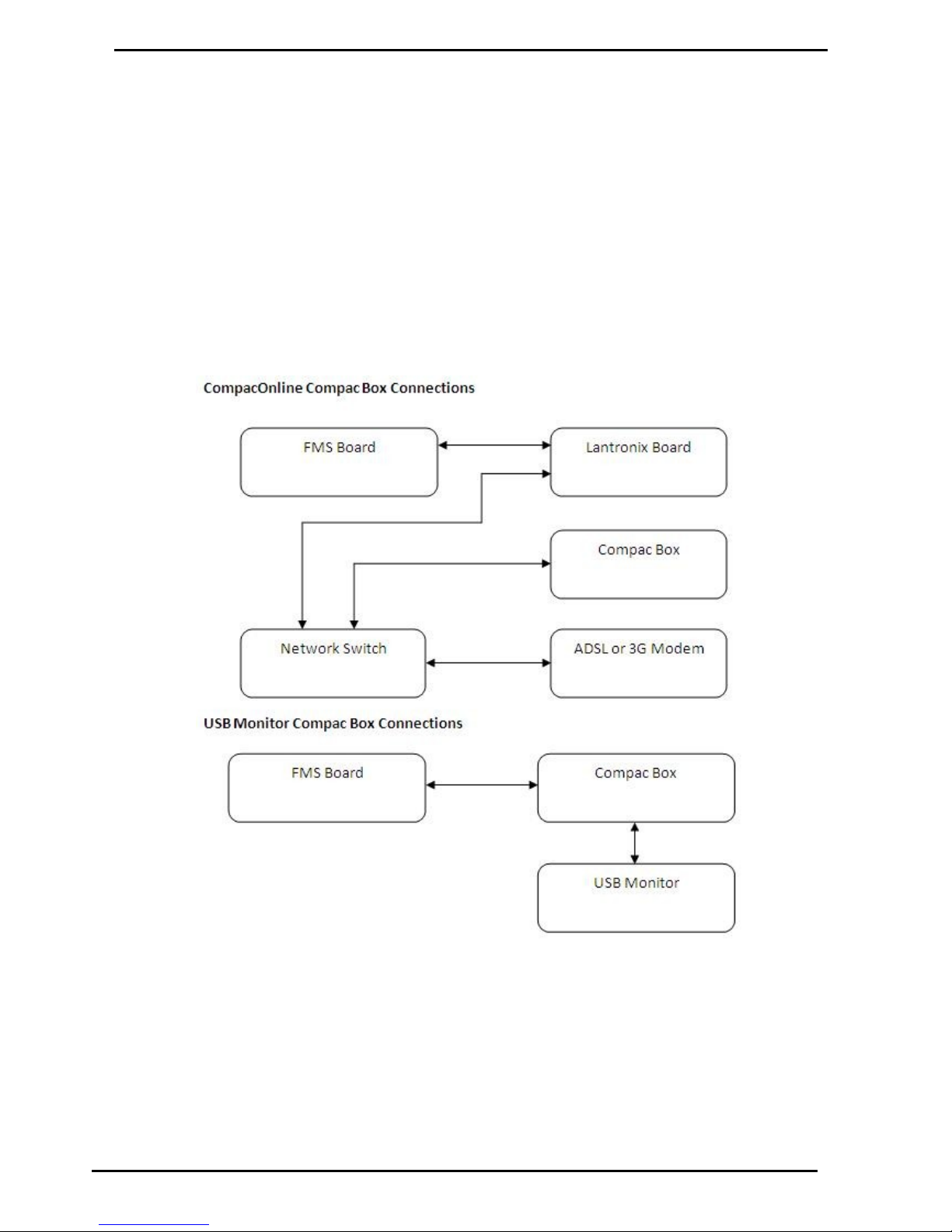
ATG / CE Box
Compac Industries Ltd.
Page 76
www.compac.co.nz
ATG / CE Box
Overview
The Compac Box is an option fitted to the unit to monitor tank gauging. The
Compac Box also communicates with the FMS board and stores
transaction information.
The tank gauging and transaction information can be accessed from the
Compac Box by using either a USB key or CompacOnline software.
For Credit Card capable units the Compac Box uses the installed PXPost
programme to communicate secure credit card information with DPS.
Compac Boxes are configured at the factory and require no set up unless
credit card capable boxes are replaced. Set up is done remotely.
For replacement refer Compac Box Replacement (see page 96).
Page 77

ATG / CE Box
Mechanical Registers
Compac Industries Ltd.
Page 77
www.compac.co.nz
Mechanical Registers
Overview
The DCA can be set up to monitor the bulk dispensing of fuel by taking
signals from a mechanical register (flow sensor) installed in the fuel line.
The signals are converted to provide a litre reading using a C4000 board
and calibrated using a conversion (K) factor.
Mechanical registers requires a C4000 board separate to the FMS board.
The C4000 board is set up as a pump communicating to the FMS board via
the C12 or C24 comms.
Connecting to DCA
There are three steps to connecting a mechanical register to the DCA.
1. Connect the pump relay(s) to the solid state relay output(s)
2. Connect the encoder(s) to the C4000 board inside the DCA
3. Calibration - Adjust the K factor(s)
Solid State Relay Outputs
The DCA can provide “clean” pairs of contacts ( maximum 3 amp each
pair) for up to 4 Mechanical Registers.
These can be used to switch a contactor or relay.
Encoder Inputs
Mount the encoder onto the flow meter in the mechanical register.
The encoder is supplied with a 1.5 metre cable. This may be cut and
additional 5 core cable spliced in between the DCA and the Encoder
Wire the encoder cable into the DIN rail mounted connectors EN1, EN2,
EN3 and EN4 as follows
The configuration code in the C4000 is set at Compac and
should not be changed.
The code is different depending on how many Mechanical Registers there
are:
1 Register C = 00001
2 Registers C = 00002
3 or 4 Registers C = 00005
Page 78

ATG / CE Box
Compac Industries Ltd.
Page 78
www.compac.co.nz
Calibration
A single litres only display is provided in the DCA for the purpose of setting
up the C4000 board and changing the k factors. It is not used in normal
operation of the DCA.
The 'K' Factor is a ratio of litres dispensed per revolution of the meter.
To follow is the method of calibration, including how to calculate the new 'K'
Factor and how to enter it in the C4000 memory.
To calibrate the dispenser/pump, dispense fuel into a certified measuring
container, and compare the display value with the amount dispensed.
Example:
Display shows 10.00 True volume 20.00
To calculate the correct 'K' Factor from the information above; firstly record
the existing 'K' Factor.
2 Factor K'' Existing
10.00
20.00
Factor K'' Existing
Amount Displayed
Amount Dispensed
Factor K'' Existing Factor K'' New
Change the existing 'K' Factor to this new value by using the ‘K’ Factor
Switch as follows.
Page 79
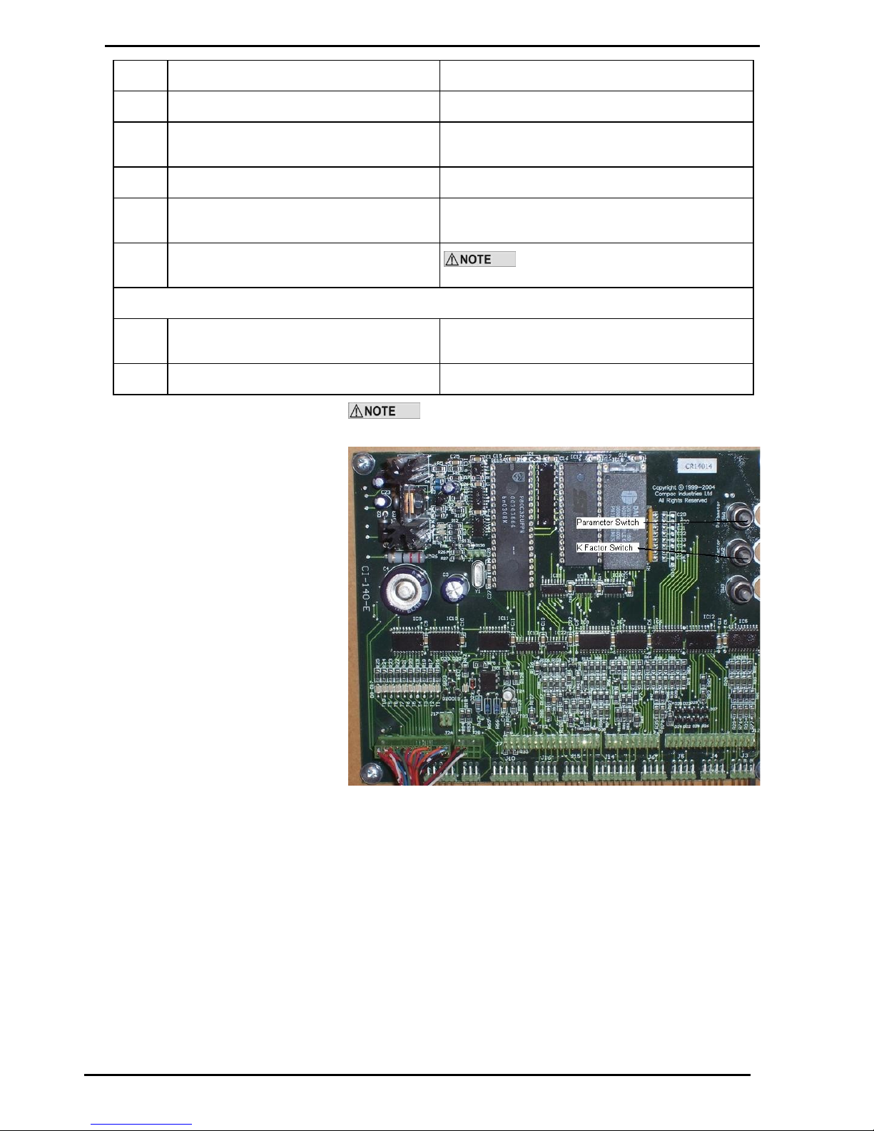
ATG / CE Box
Mechanical Registers
Compac Industries Ltd.
Page 79
www.compac.co.nz
Step
ACTION
RESULT
1
Ensure that no transactions are in progress
C4000 in idle state
2
Press and release the ‘K’ Factor switch, in quick
succession, until the desired setting is displayed.
The Litres display indicates the desired setting.
3
Press and hold the ‘K’ factor switch.
A digit, of the displayed setting, will begin to increment.
4
When the digit is correct, release the ‘K’ Factor
switch.
5
Repeat steps 3 and 4 for each digit of the setting
The C4000 will reset itself if the ‘K’ factor
switch is left for more than 10 seconds.
Continue for multiple hose units, if appropriate.
6
Press and release the ‘K’ factor switch 8 or more
times in quick succession
The setting for side “B” (or hose 2, 3, or 4) is displayed.
7
Repeat steps 3 to 5 above.
The K-Factor switch must be sealed with a lead or paper seal
after commissioning.
Figure 15: C4000 Board
Page 80
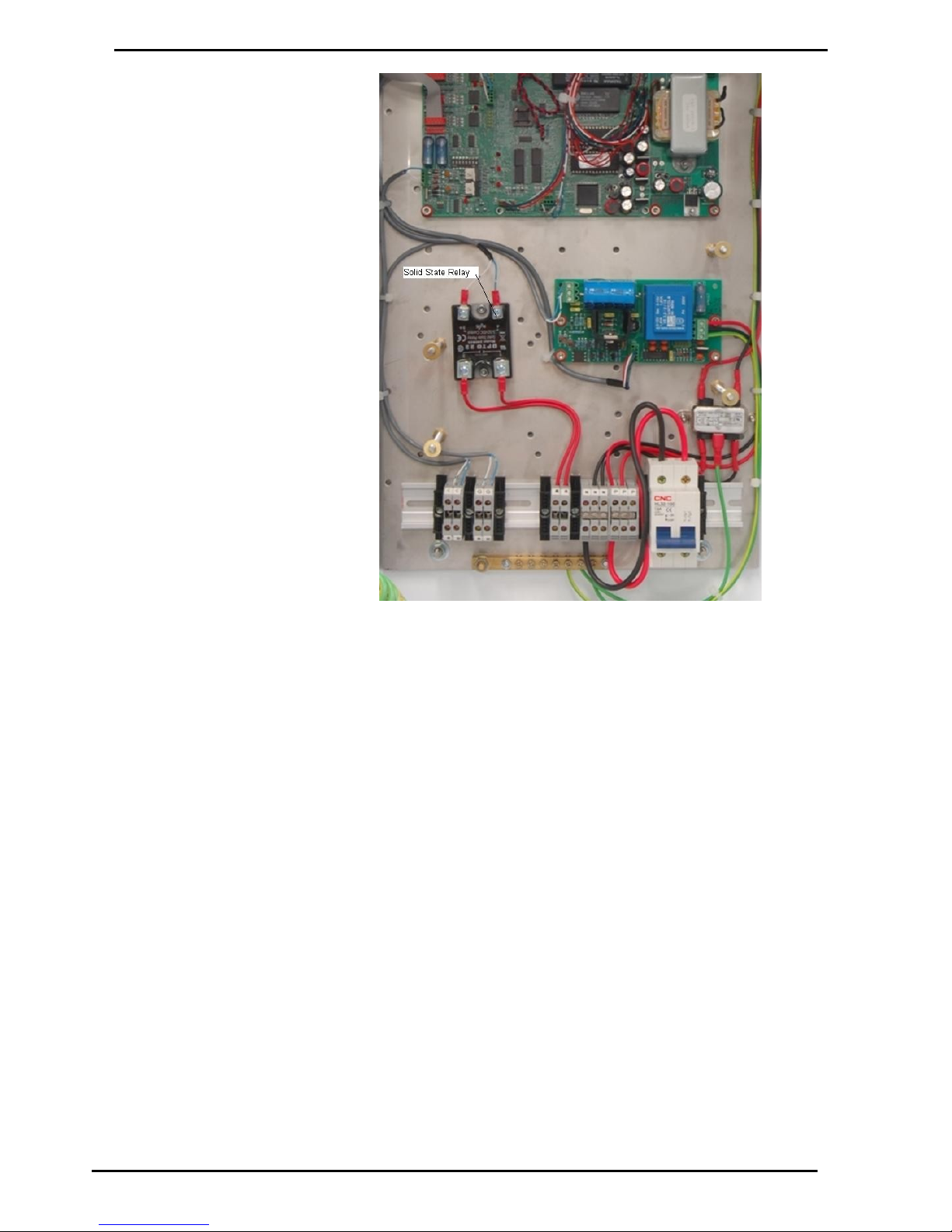
ATG / CE Box
Compac Industries Ltd.
Page 80
www.compac.co.nz
Figure 16: Solid State Relay
Page 81
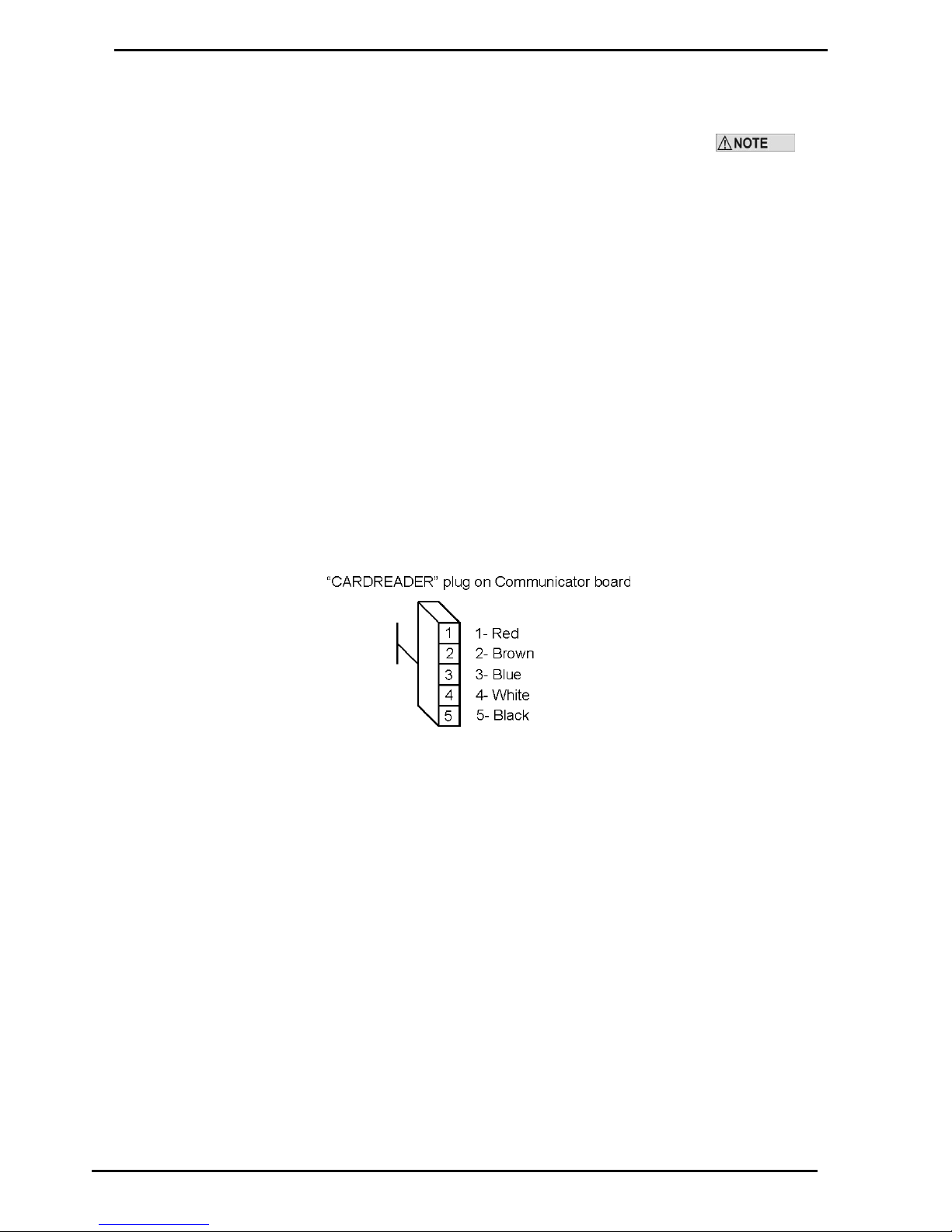
Cardreaders
Mechanical Registers
Compac Industries Ltd.
Page 81
www.compac.co.nz
Cardreaders
Units built from January 2004 onwards no longer have CIMs and use a Magtek
cardreader. These work with software version EAB1800 onwards.
This also requires B configuration code setting to work -Refer to Configuration code
tables.
Wiring connections are:
Cardreader end J3
1. Unused
2. Blue RDP
3. White CLS
4. Brown RCP
5. Unused
6. Red Vcc
7. Black Ground
8. Unused
9. Unused
Note pin 1 is marked on the cardreader pcb next to “J3”
Communicator Controller end
Page 82

Dynalink (Hayes type)
Modems
Compac Industries Ltd.
Page 82
www.compac.co.nz
Modems
Dynalink (Hayes type)
Connects to Port #1 RS232 on the rear panel of the Communicator.
There is no special setup required for the Dynalink Modem.
GSM Modem (Wavecom)
Connection
There is a ribbon cable that goes between the Port #1 RS232 D connector
and Port #1 on the Communicator board.
Cut the 'Ring Indicator' wire (connects to pin 9 on the D connector) This is
the 3rd wire in from the locking tab end of the red plug.
There is cable supplied with the Cell modem with a 15 pin high density dconnector one end.
Plug this end into the Cell modem and the other (9 pin) end into to Port #1
RS232 socket on the rear panel of the board.
Setup
No special software setup is required for the Cell Modem as the
Communicator recognises the modem when it initialises it.
The SIM card must be setup by the phone provider as Data
enabled (a different phone number will be issued)
The diagnostic LED stays ON for 20-30 seconds at power-up while it
registers on the network. It will then flash slowly when in its idle state.
During a comms session it flashes faster.
The baud rate in Netbase must be set to 9600
The Boot ROM software version in the Communicator must be BFA01052
or later
Page 83
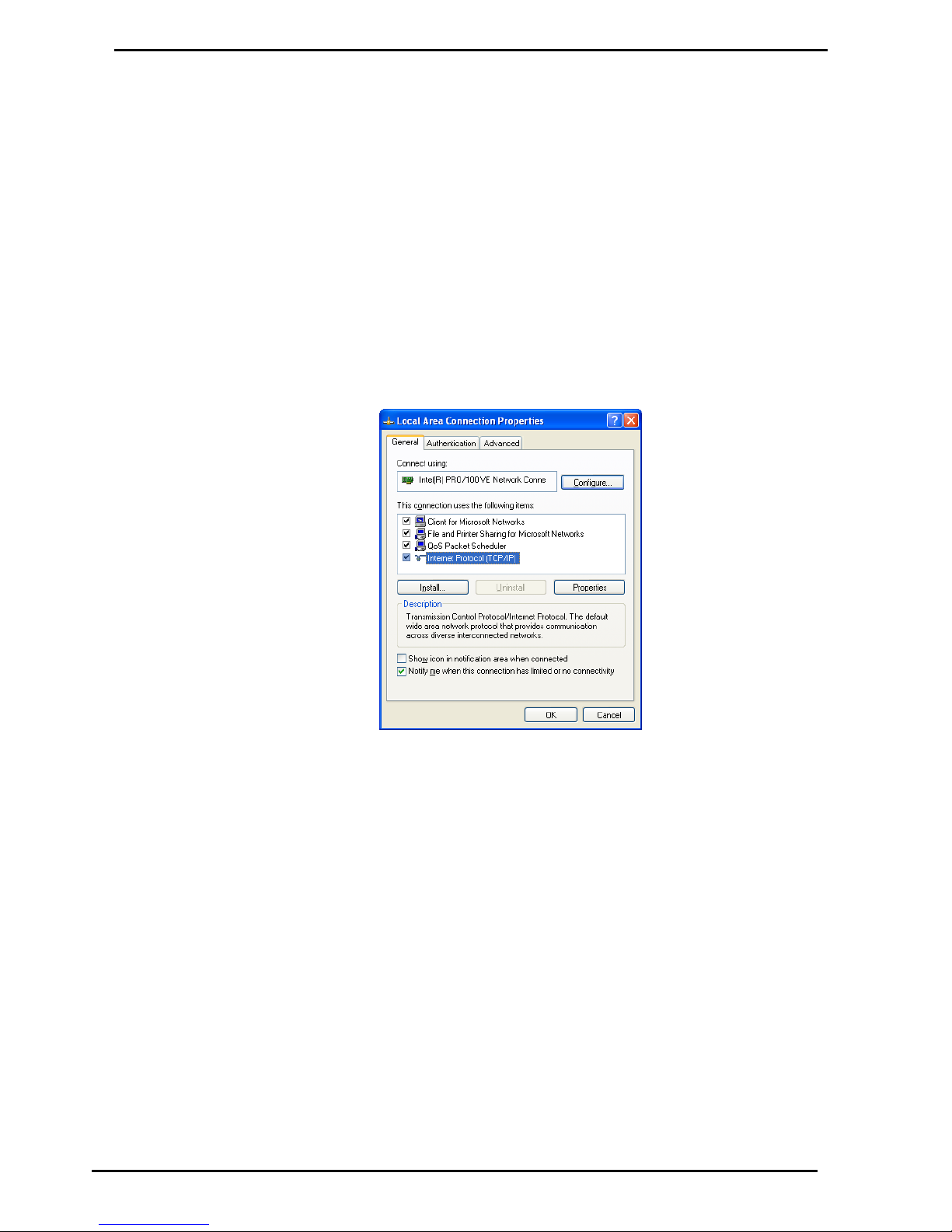
Lantronix
Compac Industries Ltd.
Page 83
www.compac.co.nz
Lantronix
If you have given Compac the IP address that you want to use, the unit will
have been set up by the factory. If you haven’t told Compac the IP address
it will be 10.0.0.122 by default.
Lantronix Setup
Step 1
Connect the Lantronix port on the communicator to your computer network.
Step 2
Change the IP address of your computer to be on the same network as the
Lantronix unit. This means going Start/Control Panel/Network Connections,
this will bring up the network connections. Right click on the connection that
you will be using and then click on properties.
Then double click on Internet Protocol (TCP/IP)
Page 84
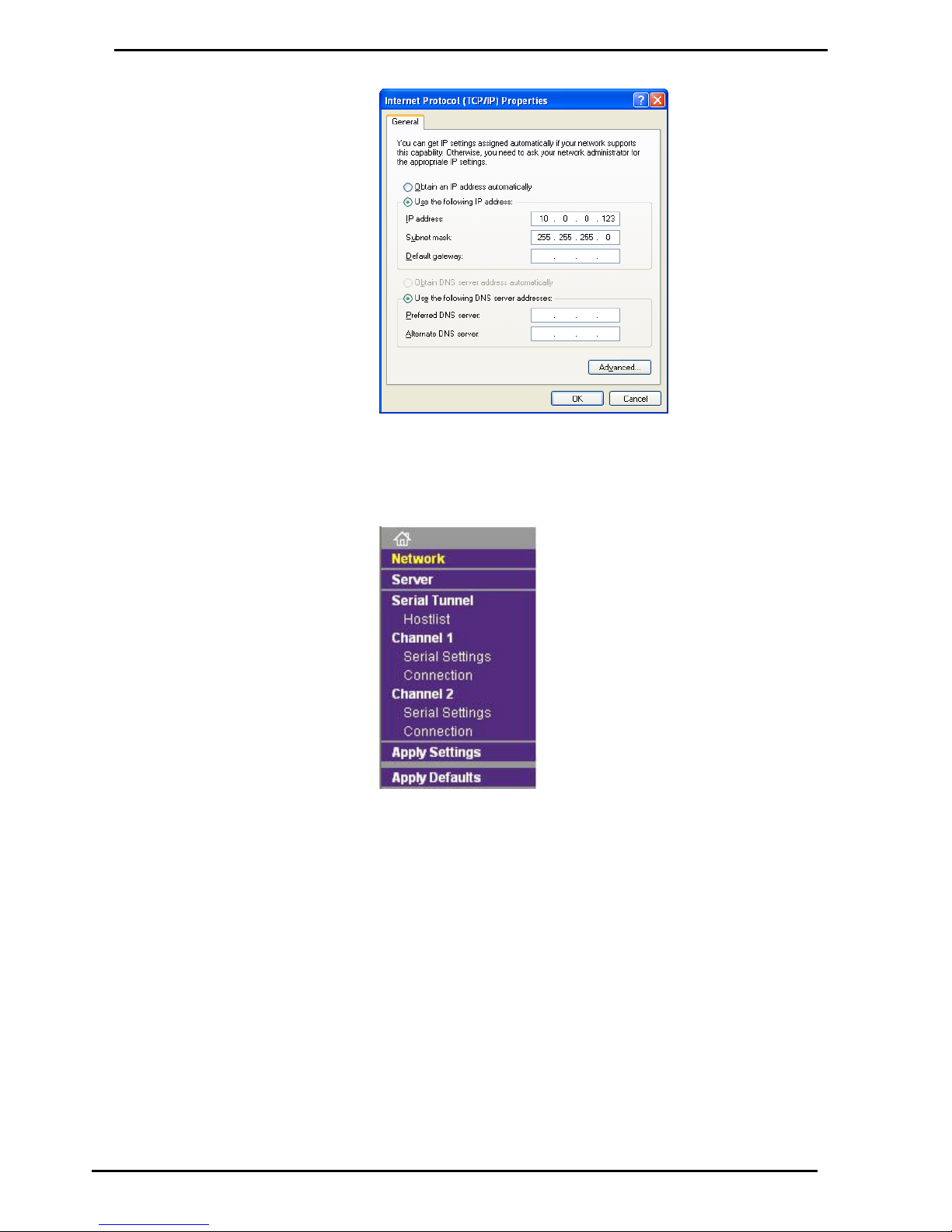
Lantronix
Compac Industries Ltd.
Page 84
www.compac.co.nz
Select “Use the following IP address”, for the IP address enter 10.0.0.123
subnet mask 255.255.255.0 this will put your computer on the same
network as the Lantronix unit.
Step 3
In your web browser type the IP address of the Lantronix unit, in our case
type http://10.0.0.122 (http://10.0.0.122) this will login into the Lantronix
unit. You will be prompted for username and a password, the default
username is “admin” with no password.
Once you are logged into the Lantronix unit click on “network” in the menu.
What you need to do is assign an IP address that will be on the same
network as the network that you are connecting the communicator to.
Warning when you are setting the IP address on the Lantronix unit it cannot
conflict with any IP address on your network. If you have a DHCP server
you will have to reserve an IP address for the Lantronix unit.
Page 85
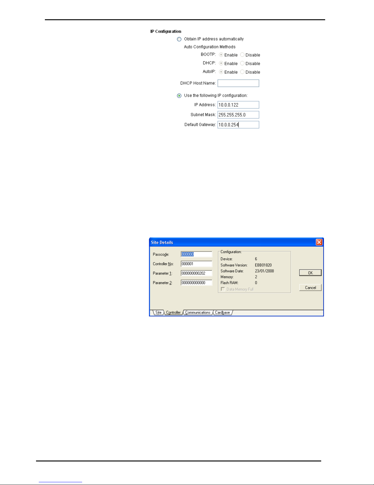
Lantronix
Compac Industries Ltd.
Page 85
www.compac.co.nz
Under IP configuration select “Use the following IP configuration”, this is
where you can set the IP address of the Lantronix, do not use the “Obtain
IP address automatically”. Remember that if you are running a DHCP
server you must reserve the IP address of the Lantronix so that the server
does not assign it to another computer.
Step 4
The communicator is now ready to be connected to the network. Once it is
connected to the network the Netbase will be able to connect to the
communicator. Before you can do this you need to make sure that the
Netbase has been setup for the communicator.
Make sure that the settings in the Communicator are the same as the
settings in the Netbase.
In this case
Passcode – 000000
Site Number– 000001
Config A (Parameter 1) = 202
Config B (Parameter 2) = 0
Page 86
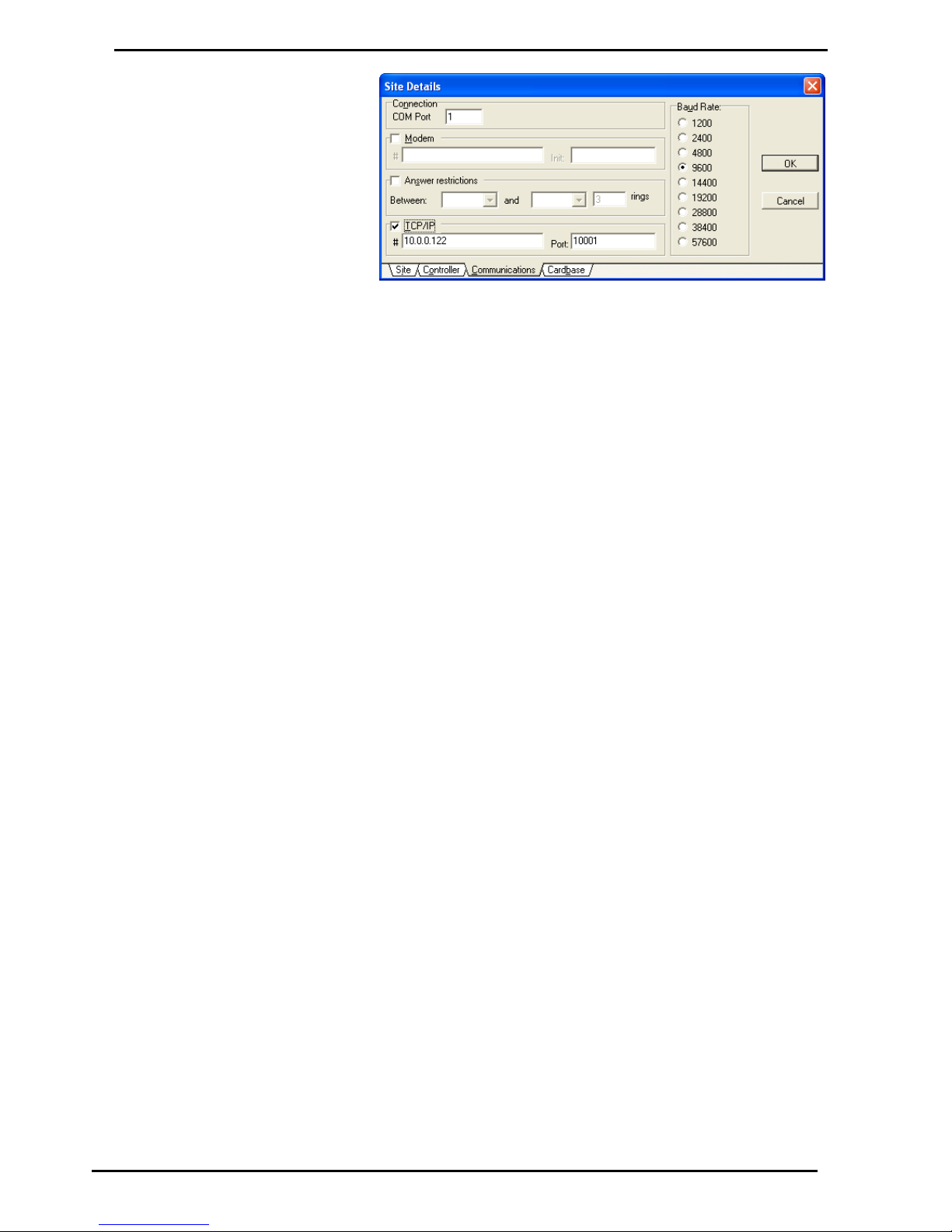
Lantronix
Compac Industries Ltd.
Page 86
www.compac.co.nz
In the Communications tab make sure that the settings are as follows.
The TCP/IP box should in ticked
The IP address (this is the IP address that you entered in step 3) for
the Lantronix unit is to be entered in the box labelled “#”.
The box labelled port contains the port that the Lantronix unit
communicates on, this is always “10001” but this can be changed.
The baud rate must be always set to 9600.
At this stage the communicator should be setup correctly and ready to
communicate with the Netbase. To test the connection try doing a "Get
date time" procedure.
Page 87
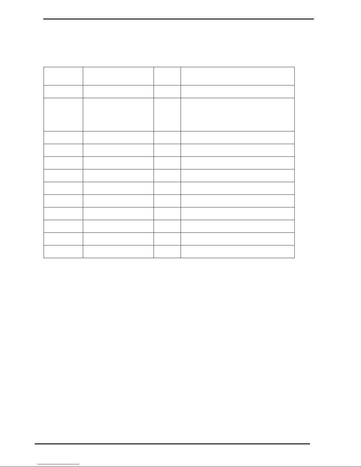
Diagnostic LEDs
Compac Industries Ltd.
Page 87
www.compac.co.nz
Diagnostic LEDs
There are a number of diagnostic LEDs on the Com FMS board to assist in the
diagnosis of comm's problems
LED name on
board
Location
Colour
Operation
POWER
Near Dipswitches
Green
ON to indicate Power Supply working
W/DOG
Near Dipswitches
Red
1. Watchdog
2. Indicates software has stopped running
(may have restarted)
3. IC fitted incorrectly or leg broken/bent
TX/1
Adjacent Port #1 TTL plug
Green
Transmit data to Modem or Direct host
RX/1
" " " "
Red
Receive data from Modem or Direct host
DCD/1
" " " "
Green
Handshaking line to Modem
TX/2
Adjacent Port #2 TTL plug
Green
To Audit Trail Printer
RX/2
" " " "
Red CTS/2
" " " "
Yellow
ON when Audit Trail Printer connected
TX/3
Adjacent Port #3 TTL plug
Green
Used for Receipt Printer and Commander
RX/3
" " " "
Red TX/4
Adjacent Port #4 TTL plug
Green
Only used when Gilbarco or Email pumps
RX/4
" " " "
Red
Running on comms channel 2
Page 88
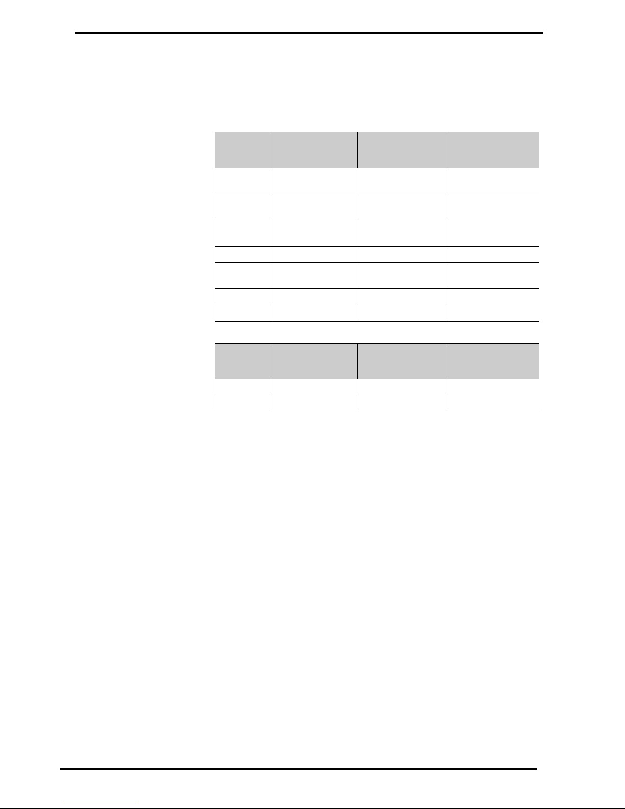
Diagnostic LEDs in a system with Compac comms only
Diagnostic LEDs
Compac Industries Ltd.
Page 88
www.compac.co.nz
Diagnostic LEDs in a system with Compac comms only
In a typical system (with Compac pumps only) this is how the diagnostic LEDs will
appear.
Com FMS Board
LED
Comms
working
correctly
Comms wiring
reversed
Short on
comms
To Pumps /
5
Flashes
Flashes
Flashes (very fast)
From
Pumps / 5
Flashes
Flashes
Flashes (very fast)
Comm
Short / 5
OFF
ON
Flashes (very fast)
TX / 5
Flashes
Flashes
Flashes
RX / 5
Flashes (faster
than TX / 5)
Stuck ON
Stuck ON
WDOG
OFF
OFF
OFF
POWER
ON
ON
ON
C4000 Board
LED
Comms
working
correctly
Comms wiring
reversed
Short on
comms
D6
Flashes
Stuck ON
OFF
D7
Flashes
OFF
OFF
Page 89

Reports
Compac Industries Ltd.
Page 89
www.compac.co.nz
Reports
Reports can be printed directly from the DCA if the correct printer is
connected to a Printer Interface.
If a PC running NETBASE is used the printer is normally used to keep an
audit trail log only.
Reports are selected from DCA PIN Pad menus, and are only printed if an
appropriate report printer is connected to RS232 Port 2 on the Controller
and is ON LINE.
Accessing Reports
To access reports enter the Passcode at the PIN Pad. Go to the report
menu. The following reports are available:
Shift Report
This option prints tank reconciliation data, resetable card totals, and the
date and time of the last memory clearance.
Transactions Report
This prints the following data chronologically card by card (excluding
anything previously deleted):
Card/account number; site and reference numbers; date and time of
transaction; pump number; product and unit price; quantity issued and total
price
Transactions & Shift Report
This prints the Shift Report then the Transactions Report.
Site Status Report
This report prints the following data: Site name and number; date and time;
non-resetable totals for each product and pump; product information
(including unit price, total issued and value); and how full the transaction
buffer is. It also automatically prints the tank status report when tank
gauging is installed.
Tank Status Report
This report is only available with tank gauging. It prints the following:
Site number; date and time; tank number and tank information - quantity
and status (low level, high level or normal), designated product and ullage.
Card Status Information
This specifies the current validity or non-validity of all cards in the system.
Single Card Transactions Report
This report is the same as for the Transactions Report except that a
specific card may be selected.
All Buffer Data Report
This report is the same as for the Shift Report and Transactions Report,
except that all transactions in the memory buffer are printed, regardless of
whether or not they have been deleted.
When deleting is carried out, 'deleted' transactions are not
actually erased, but can be overwritten at any stage afterward. This option
allows printing of all transactions not yet overwritten (with no guarantee that
specific deleted transactions will still be recoverable).
Transaction Data by Date Range
This report is the same as for the All Buffer Data Report (that is, all
transaction data including that of surviving deleted transactions), except
that date parameters can be set so that only information from a specified
period is printed out.
Page 90

Deleting Transactions
Reports
Compac Industries Ltd.
Page 90
www.compac.co.nz
Deleting Transactions
Deleting Transactions
Transactions stored in the Controller memory can only be deleted once
they have been report 'printed'. Therefore, before deleting can proceed, a
report (with transactions) must be printed unless:
The Controller is configured for deleting after 'totals only reporting', or
The transactions can be effectively printed by uploading them to a host
computer, either directly or via a modem.
Once one of the above has been completed, and this information is verified
and secure, deleting can proceed.
It is important to have a reasonably accurate idea of the
transaction buffer capacity, so that transactions can be reported and
deleted before the transaction buffer fills completely. A filled buffer will
disable further transactions until it is cleared. A percentage reading of how
full the transaction buffer is included in the printout which occurs on 'power
up'.
Once deleted, transactions can be overwritten, with no guarantee of
retrieval.
Page 91
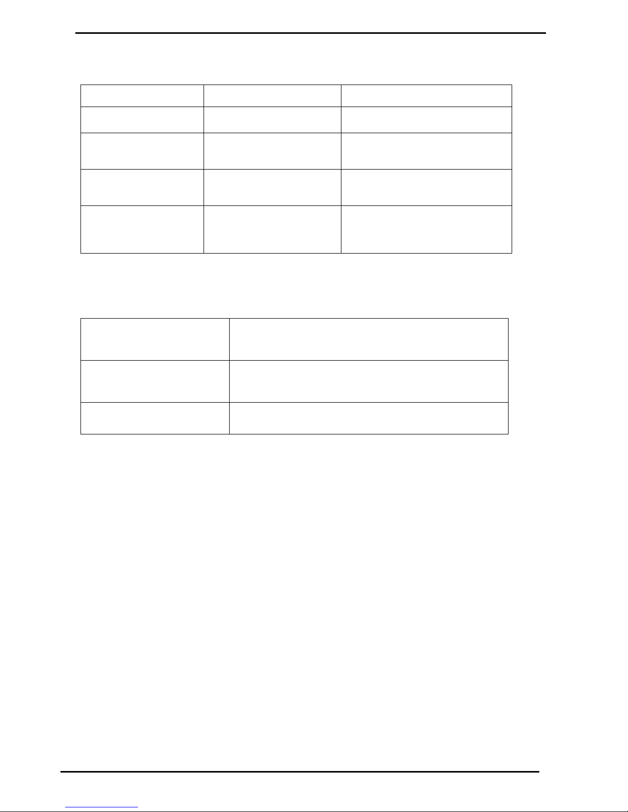
Troubleshooting
Compac Industries Ltd.
Page 91
www.compac.co.nz
Troubleshooting
Symptom
Problem
Solution
One pump drags the comms
down on the other pumps
An unused hose has been
allocated to a group
Check group allocations for that pump
“Receipt unavailable”
displayed keeps trying to
initialise GPRS modem
Cardreader not plugged in
when unit was powered up
Plug cardreader in and re-power
“Receipt unavailable”
displayed
Paper not through far enough
to be detected by paper out
sensor
Press paper feed button momentarily
Cardreader does nothing
when card swiped
Cardreader was plugged in
after the unit was powered up
Cardreader unplugged
Re-power the unit
Plug cardreader in
Error Messages
PRINTER NOT AVAILABLE
Try pressing Paper feed button on printer, check that paper is
installed correctly. Otherwise there is a fault in the printer - Call a
service agent.
BUFFER FULL
The memory is full. Old transactions need to be deleted before any
more transactions can be made - Refer to Deleting Transactions (see
page 90).
Pump unavailable or Pump
OFF LINE
Comms problem between the unit and the pumps.
Page 92

Com FMS Board Replacement (DCA)
Service and Upgrade Procedures
Compac Industries Ltd.
Page 92
www.compac.co.nz
Service and Upgrade Procedures
The unit is designed to perform many different operations depending on the
application. The contents of the cabinets shown in the following procedures may
not reflect the actual cabinet you are working on.
Com FMS Board Replacement (DCA)
Always take anti-static precautions when working with electronic
components. i.e., wearing a wristband with an earth strap.
Always take precautions to avoid arcs and short circuits that may
damage sensitive components.
Tools Required to Replace
the FMS Board
3 mm allen key
Replacement FMS board.
Check if the board has memory and software chips (consult with
Compac Help Desk to see if you can use existing software or if you also need to
install new chips).
Removal
1. Turn off the mains switch.
2. Remove any components that may obstruct the easy removal of the board.
Note the locations and connections to the parts removed
3. Unplug the connections to the board.
4. Undo the four machine screws holding the board and remove it.
5. Remove the memory and software chips from the FMS board if they are to be
re-used and installed into the replacement FMS board.
Replacement
1. Replace the Comm FMS board and reconnect.
2. Once a new PCB has been installed in the electronic module install the
memory and software chips onto the appropriate sockets on the board.
3. Replace all the components that were removed to access the board.
4. Verify the site pump and comms settings are correct. If the memory and
software used are new, the site specific settings such as tanks / groups will
need to be entered. Refer Main Menu Options (see page 41).
5. Set the time and date. Refer to Setting the Clock (see page 47).
Page 93
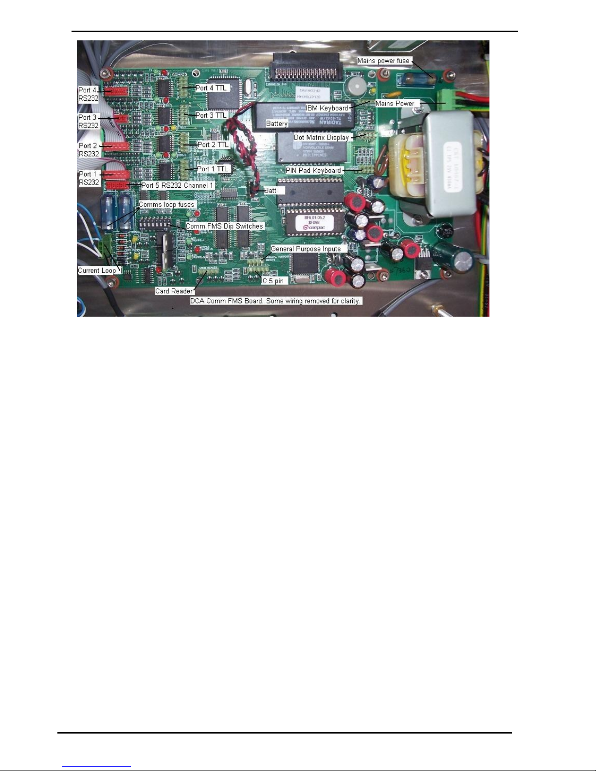
Service and Upgrade Procedures
Com FMS Board Replacement (DCA)
Compac Industries Ltd.
Page 93
www.compac.co.nz
Figure 17: Comm FMS Board
connections
Page 94

Com FMS Board Replacement (DCA)
Service and Upgrade Procedures
Compac Industries Ltd.
Page 94
www.compac.co.nz
Due to the varied configurations of the units, all combinations of wiring can
not be listed here. Take careful note of all connections before removal and
use the list below as a guide only. The RS232 ports are RS232 mirrors of
the TTL ports.
Component
Wire Colours
Comment
Port 1 RS232
Modem / direct host
Port 2 RS232
Audit trail printer or GPRS modem
Port 3 RS232
Port 4 RS232
Tank gauging or Gilbarco comm's
Port 5 RS232
RS232 output of current loop for long distance pump comm's
Port 1 TTL
Connects to Lantronix board for TCPIP communication with
CompacOnline, Netbase or Compac Box.
Port 2 TTL
Used in conjunction with Port 1 TTL
Port 3 TTL
Receipt printer
Port 4 TTL
IC (5pin)
Power for capacitance keypad.
Card Reader
General
Purpose
Inputs
Mains Power
Red/Black/Green
Uses 3 pin plug wired: Phase-red, Neutral-black and Earth-green
PIN Pad
Keyboard
Dot Matrix
Display
IBM
Keyboard
Not used
Batt
Red, Black
3.6V lithium battery
Dip Switches
Use DIP switches to allocate port functions. If replacing a board, make sure
DIP switches match up.
Use the above table as a guide only as wire colours can
change during production and after servicing.
Page 95
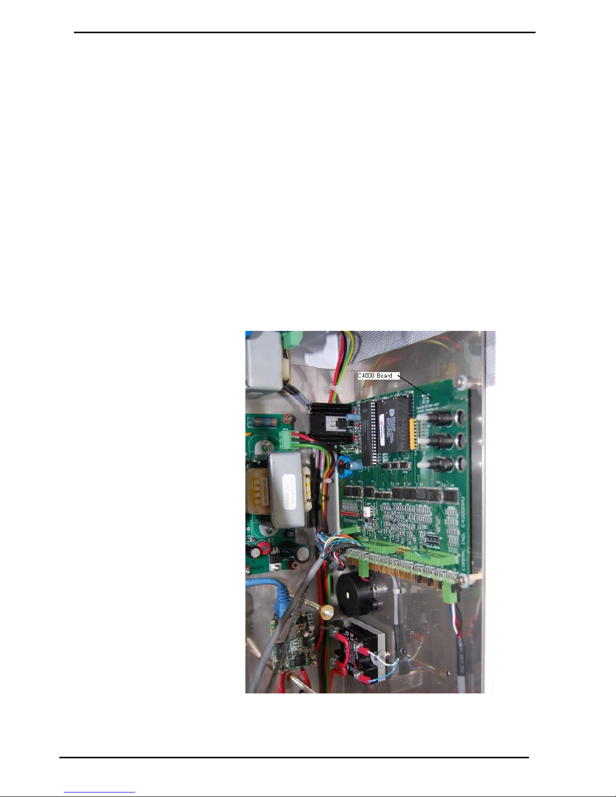
Service and Upgrade Procedures
C4000 Board Replacement
Compac Industries Ltd.
Page 95
www.compac.co.nz
C4000 Board Replacement
Depending on the model of unit the C4000 board (or boards) may be
mounted in different positions. The C4000 board is recognisable by the
three parameter switches on the board.
Refer to the C4000 Master Manual for more information.
Removal & Replacement
Due to the varied mounting, there are no specific instructions.
Remove all components that may interfere with the removal of the board,
taking note of the position and polarity of all wiring.
Remove the C4000 board.
Replacement is the opposite of removal. If a software chip was not included
on the replacement board, use the chip from the old board, refer to the
C4000 Master Manual for more information.
Configuration
The C4000 board can be set up in different ways depending on whether it
is being used for CWID authorisation or for reporting mechanical register
outputs. Refer to Compac and the C4000 Master Manual for details.
Figure 18: C4000 Board
Page 96
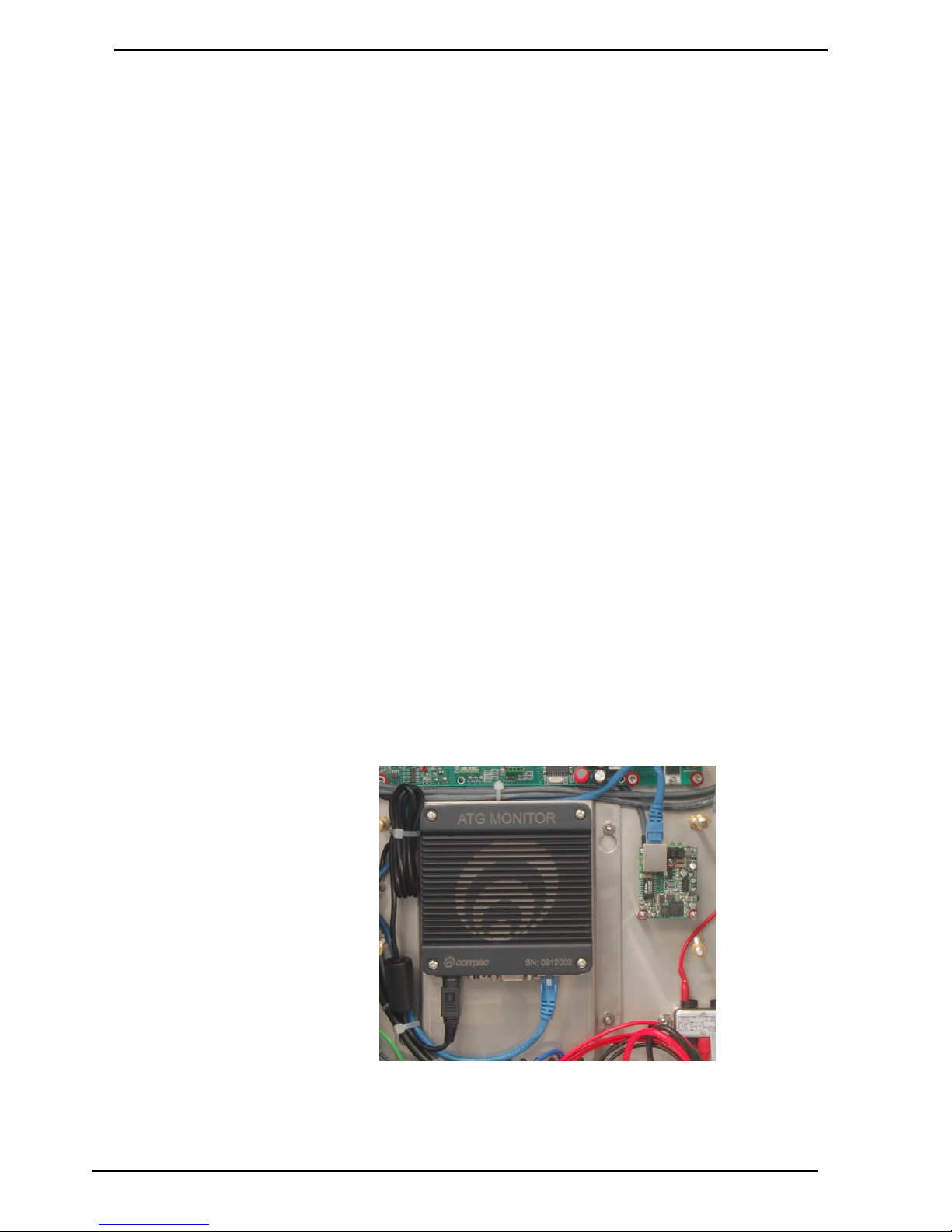
Compac Box Replacement
Service and Upgrade Procedures
Compac Industries Ltd.
Page 96
www.compac.co.nz
Compac Box Replacement
To Replace the Compac Box you will
need
7mm Nut driver
Replacement Compac Box FE-CU-0001
Cable ties
Cutters
Laptop and network cable or keyboard, mouse and screen (for CC
DCA)
Method
Turn off the power to the unit
Remove the perspex cover and any components that restrict access to the
Compac Box taking note of location and connections of all parts used.
Unplug all connections leading into the Compac Box, noting their positions.
Loosen the 4 nuts retaining the Compac Box mounting plate to the back
wall of the cabinet. Lift and carefully remove the Compac Box mounting
plate.
Remove the Compac Box from the mounting plate.
Replacement
Replacement is the reverse of removal. Ensure the perspex cover is
replaced.
Configuring an Compac Box (Tank
Gauging Only)
No configuration is required for tank gauging only connections.
Configuring an Compac Box (Credit
card capable units)
Contact Compac who will remotely configure the unit. You may be asked to
plug a laptop or screen, keyboard and mouse in to the Compac Box to do
initial configuration.
Figure 19: Compac Box (may be labelled as ATG Monitor)
Page 97
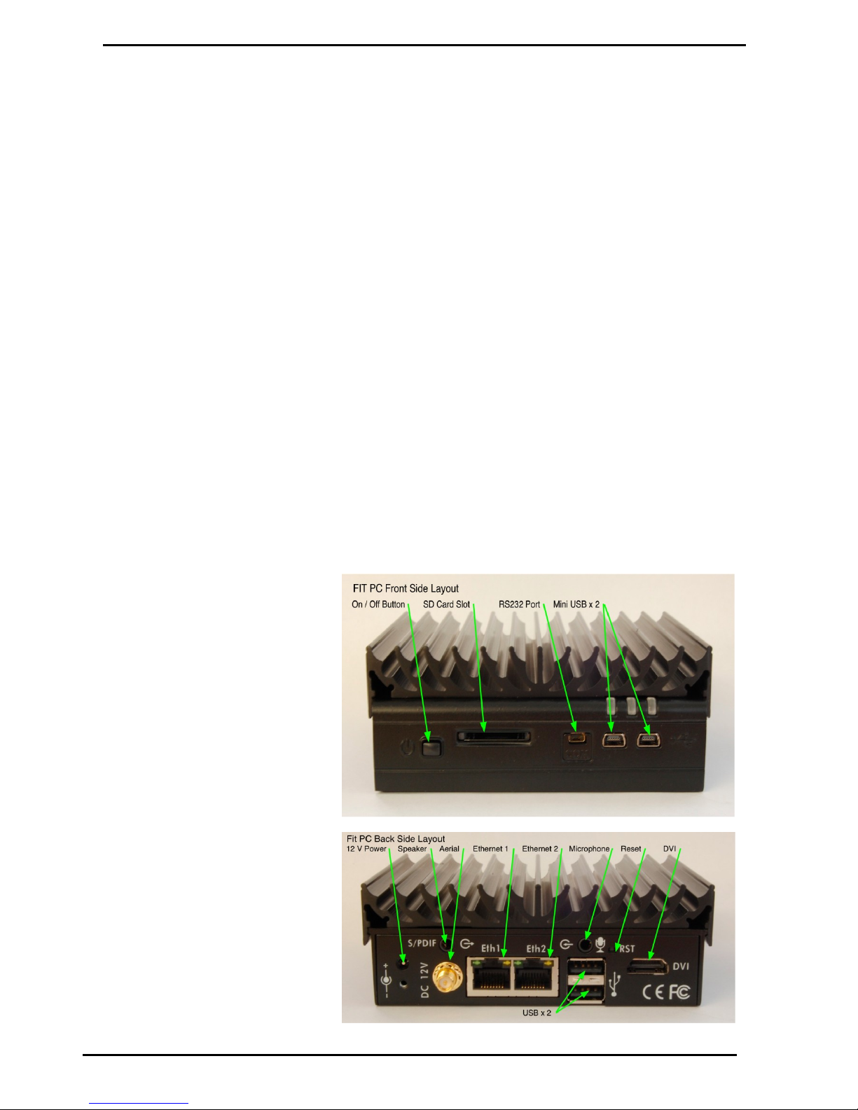
Service and Upgrade Procedures
Fit PC Replacement
Compac Industries Ltd.
Page 97
www.compac.co.nz
Fit PC Replacement
The Fit PC is installed instead of a Compac Box when a wireless LAN
connection is required. The Fit PC is recognised by the large heat sink.
To Replace the Fit PC you will need
Replacement Fit PC (excluding heat sink) F-BA-EMB-PC2IWE
Cable ties
Cutters
Laptop and network cable or keyboard, mouse and screen
Method
Turn off the power to the unit
Remove the perspex cover and any components that restrict access to the
Fit PC taking note of location and connections of all parts used.
Unplug all connections leading into the Fit PC, noting their positions. Note
that the power plug is attached to the box with a screw.
Twist the Fit PC box anti-clockwise to release the box from its mounting
plate. Lift and carefully remove the Fit PC.
Slide the heat sink off the unit.
Replacement
Replacement is the reverse of removal. Ensure the aerial is connected (if
wireless connection) and that the perspex cover is replaced.
When the unit is re-powered, check that the fit PC is turned on and the
green power LED is lit. If no lights are showing, press the On/Off button to
turn it on.
Configuring a Fit PC (Credit card
capable units)
Contact Compac who will remotely configure the unit. You may be asked to
plug a laptop or screen, keyboard and mouse in to the Fit PC to do initial
configuration.
Page 98
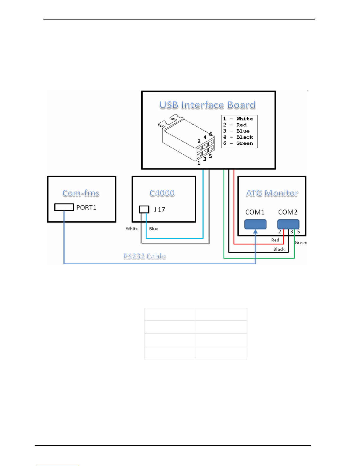
Wiring a USB Module
Service and Upgrade Procedures
Compac Industries Ltd.
Page 98
www.compac.co.nz
Wiring a USB Module
The diagram below shows the wiring diagram for USB interface board to a
Compac Box. The power for the USB Interface Board is off J17 on the
C4000 Process Board. An RS232 cable come off Port1 on the Com-fms
board to the Com1socket on the Compac Box.
The USB cable from the USB Module plugs into the USB port on the
Compac Box (not shown here).
Figure 20: Wiring Diagram for USB interface board to ATG Monitor
Attach the RS232 cable wires to the plug terminals so they match the
following table:
Wire
Pin
Red 2 Black
3
Green
5
Page 99
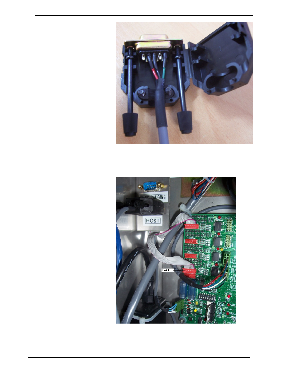
Service and Upgrade Procedures
Wiring a USB Module
Compac Industries Ltd.
Page 99
www.compac.co.nz
Figure 21: USB Module to Compac Box (COM2) Wiring
Figure 22: Location of Port 1 on Com FMS board
Page 100
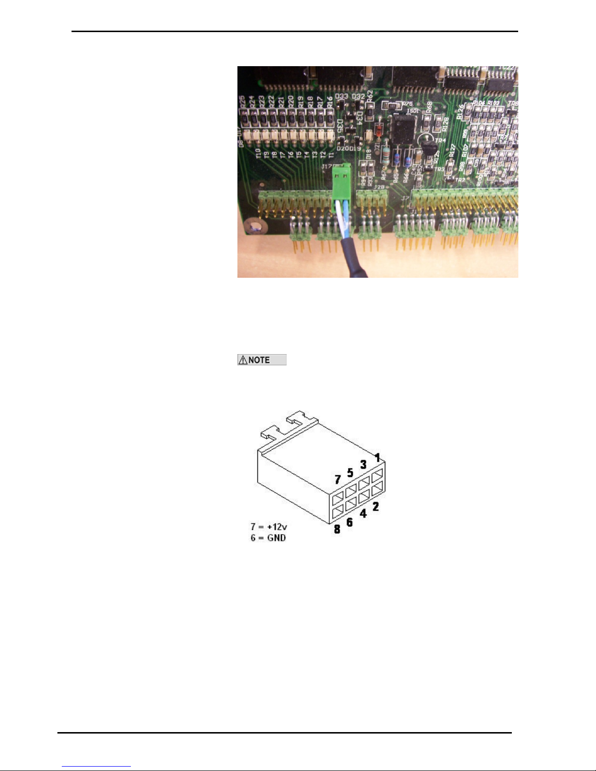
Wiring a USB Module
Service and Upgrade Procedures
Compac Industries Ltd.
Page 100
www.compac.co.nz
Plug the RS232 cable into Port1 on the Com-FMS board.
Figure 23: 12V Supply Cable from C4000 to USB Interface Board
Plug the two-core cable into J17 on the C4000 processor board. The white
wire goes into +12V and blue wire goes to ground.
If the unit does not have a C4000 processor board you need
to obtain a 12 volt power supply either from a power transformer or by
connecting into the TTL port of the Com-FMS board as shown.
Wire both RS232 cables to the Compac Box as shown and plug the 6-way
connector into the USB Interface board. The USB cable off the USB
Interface board should be plugged into the USB port on the Compac Box.
 Loading...