

Page 1

C4000 Master Manual
Version 1.0.0
Page 2

ii
Conditions of Use
Read this manual completely before working on or
making adjustments to the Compac equipment.
Compac Industries Limited accepts no liability for
personal injury or property damage resulting from
working on or adjusting this unit incorrectly or
without authorisation.
Along with any warnings, instructions, and
procedures in this manual, you should also observe
any other common sense procedures that are
generally applicable to equipment of this type.
Failure to comply with any warnings, instructions,
procedures, or any other common sense procedures
may result in injury, equipment damage, property
damage, or poor performance of the Compac
equipment
The major hazard involved with installing and
operating the unit is electrical shock. This hazard
can be avoided if you adhere to the procedures in
this manual and exercise all due care.
Compac Industries Limited accepts no liability for
direct, indirect, incidental, special, or consequential
damages resulting from failure to follow any
warnings, instructions, and procedures in this
manual, or any other common sense procedures
generally applicable to equipment of this type. The
foregoing limitation extends to damages to person or
property caused by the unit or damages resulting
from the inability to use the unit including loss of
profits, loss of products, loss of power supply, the
cost of arranging an alternative power supply, and
loss of time, whether incurred by the user or their
employees, the installer, the commissioner, a
service technician, or any third party.
Compac Industries Limited reserves the right to
change the specifications of its products or the
information in this manual without necessarily
notifying its users.
Variations in installation and operating conditions
may affect the unit's performance. Compac
Industries Limited has no control over each
installation's unique operating environment. Hence,
Compac Industries Limited makes no
representations or warranties concerning the
performance of the unit under the actual operating
conditions prevailing at the installation. A technical
expert of your choosing should validate all operating
parameters for each application.
Compac Industries Limited has made every effort
to explain all servicing procedures, warnings, and
safety precautions as clearly and completely as
possible. However, due to the range of operating
environments, it is not possible to anticipate every
issue that may arise. This manual is intended to
provide general guidance. For specific guidance
and technical support, contact your authorised
Compac supplier, using the contact details in the
Product Identification section
Information in this manual shall not be deemed a
warranty, representation, or guarantee. For
warranty provisions applicable to this unit, please
refer to the warranty provided by the supplier.
Unless otherwise noted, references to brand
names, product names, or trademarks constitute
the intellectual property of the owner thereof.
Subject to your right to use the unit, Compac does
not convey any right, title, or interest in its
intellectual property, including and without
limitation, its patents, copyrights, and know-how.
Every effort has been made to ensure the accuracy
of this document. However, it may contain technical
inaccuracies or typographical errors. Compac
Industries Limited assumes no responsibility for
and disclaims all liability of such inaccuracies,
errors or omissions in this publication.
Page 3

iii
Contents
Product Identification C4000 Processor ......................................................................................................................... v
Document Control Information ........................................................................................................................................ 6
Symbols and Units of Measure ........................................................................................................................................ 7
Safety - C4000 Controller .................................................................................................................................................. 8
Mechanical Safety .................................................................................................................................................... 8
Electrical Safety ....................................................................................................................................................... 8
Safety Precautions ................................................................................................................................................... 8
Electrical Commissioning ................................................................................................................................................ 9
Cable Requirements ................................................................................................................................................ 9
Connecting Mains Power and Communication ...................................................................................................... 10
Electrical Commissioning C4000 ........................................................................................................................... 11
Main Features .................................................................................................................................................................. 12
C4000 Components ............................................................................................................................................... 12
Configurations ........................................................................................................................................................ 13
Set-up Modes ................................................................................................................................................................... 16
Configuration Code ................................................................................................................................................ 16
'b' Settings .............................................................................................................................................................. 18
C4000 Set-up ......................................................................................................................................................... 21
Calibration ('K') Factor............................................................................................................................................ 23
No Flow Cut-Off Timer ........................................................................................................................................... 25
Display (Litres) Resolution ..................................................................................................................................... 26
Solenoid Delay ....................................................................................................................................................... 27
Pre-Set Cut-Off ...................................................................................................................................................... 28
Further Settings Available on the 'K' Factor Switch ................................................................................................ 28
Parameter Switch ................................................................................................................................................... 33
Printer Set-up ......................................................................................................................................................... 40
Displaying and Printing Totals ................................................................................................................................ 41
Basic Systems (Comcard Compin & CWIDKey) .................................................................................................... 43
Electrical Wiring C4000................................................................................................................................................... 45
Compac Wireless Transceiver ............................................................................................................................... 49
Displays: Litres only, Retail, Multi-price & Preset ................................................................................................... 52
End of Sale Indications ................................................................................................................................................... 58
Software Upgrade Procedure ................................................................................................................................ ......... 59
Solid State Relays (Triacs) ............................................................................................................................................. 61
Triacs C4000 Single, Dual & Quad ........................................................................................................................ 62
Triacs C4000 MPD6 & MPP6 side A ...................................................................................................................... 63
Triacs C4000 LPG Single/Dual, CNG & Bulk Meter ............................................................................................... 64
High Current Triac Option ...................................................................................................................................... 65
Indicator LEDs ................................................................................................ ................................................................. 66
Fault Finding .................................................................................................................................................................... 68
Error Codes ............................................................................................................................................................ 70
Error Messages ...................................................................................................................................................... 71
Page 4

iv
Appendix A ...................................................................................................................................................................... 72
C4000 with RS232 Wiring ...................................................................................................................................... 72
RS485 Wiring ......................................................................................................................................................... 73
C4000 with RS485 Wiring ...................................................................................................................................... 75
Gilbarco Interface Wiring........................................................................................................................................ 76
Glossary of Terms ........................................................................................................................................................... 77
Page 5

v
Product Identification C4000 Processor
Manual Title
C4000 Processor Master Manual
Models Covered
All C4000 Series
Application
Power Supply
220 - 240 VAC; 50 Hz; 2 Amp +/- 10%
Related Manuals
Title
Publication Date
C4000 Futra Manual
October 2008
ComFutra Installation &
Service Manual
September 2010
C4000 LPG Manual
Validity
Compac Industries Limited reserves the right to revise or change product
specifications at any time. This publication describes the state of the
C4000 processor at the time of publication and may not reflect the product
at all times in the past or in the future.
Manufacturer Contact
Details
The Compac C4000 processor is designed and manufactured by:
Compac Industries Limited
52 Walls Road, Penrose, Auckland 1061, New Zealand
P.O. Box 12-417, Penrose, Auckland 1641, New Zealand
Phone: + 64 9 579 2094
Fax: + 64 9 579 0635
www.compac.co.nz
Copyright ©2010 Compac Industries Limited, All Rights Reserved
Page 6

Document Control Information
Compac Industries Ltd.
Page 6
www.compac.co.nz
Document Control Information
Document Information and Revision History
Document Details:
C4000 Master Manual
File Name and Location:
G:\Masters\Manuals\Authorised Manuals\C4000
Current Revision Author(s):
R Lacey
Authorised By:
A Kingstone
Release Date: 06/09/2010
Version
Date
Author(s)
Revision Notes
1.0.0
06/09/2010
R Lacey
Added RS485 info
Distribution
Name
Indicator
Location
Page 7

Symbols and Units of Measure
Compac Industries Ltd.
Page 7
www.compac.co.nz
Symbols and Units of Measure
Symbols
Symbols are used in this manual to highlight information that is critical
to the safety of people and equipment, and for the safe and correct
operation of the Compac equipment
An extreme hazard that may result in death or injury if
proper precautions are not taken.
A reminder of safety practices or unsafe practices that
could result in personal injury or damage to associated equipment.
A reminder of safety practices or unsafe practices that
could result in damage to associated equipment and/or voids the
warranty.
Important information essential to the installation and
operation of the Compac equipment
Units of Measure
The following units of measure are used in this manual:
Unit
Measure
Pressure
Bar (bar)
Temperature
Degrees Celsius (°C)
Volume
Litres (L)
Cubic Metres (m³)
Mass
Kilograms (kg)
Length
Metres (m)
Millimetres (mm)
Microns, Micrometres (m)
Inches (")
Torque
Newton Metres (Nm)
Voltage
Volts (V)
Current
Amps (A)
Frequency
Frequency (Hz)
Page 8

Mechanical Safety
Safety - C4000 Controller
Compac Industries Ltd.
Page 8
www.compac.co.nz
Safety - C4000 Controller
You must adhere to the following safety precautions at all times when
working on the Compac C4000 processor. Failure to observe these safety
precautions could result in damage to the Compac C4000 processor, injury,
or death.
Make sure that you read and understand all safety precautions before
operating the Compac Compac C4000 processor.
Mechanical Safety
Observe the following mechanical precautions:
Make sure that the service area is thoroughly clean when
servicing. Dust and dirt entering the components reduce the life span of the
components and can affect operation.
Electrical Safety
Observe the following electrical precautions:
Always turn off the power to the Compac C4000 processor
before opening the flame proof box. Never touch wiring or components
inside the high voltage area with the power on.
Always turn off the power to the Compac C4000 processor at
the mains switch before removing or replacing software or memory ICs.
Always take basic anti-static precautions when working on the
electronics, i.e., wearing a wristband with an earth strap.
Safety Precautions
The C4000 head, and its associated circuits and wiring, is a
certified piece of electrical equipment approved for use in a hazardous area
(Class 1 Zone 1, Group IIA T3). Only parts identical to those covered by the
certification may be used where the integrity of the intrinsic safety may be
affected. All circuit boards are to be repaired only by Compac Industries
Ltd.
Static Electricity Precautions
Electronic components used are sensitive to static. Please take anti-static
precautions.
All circuit boards must be carried and transported in static-shielded bags.
An anti-static wrist strap should be worn and connected correctly when
working on any electronic equipment. If an anti-static wrist strap is
unavailable, or in an emergency, hold onto an earthed part of the
pump/dispenser frame whilst working on the equipment. This is not a
recommended alternative to wearing an anti-static wrist strap.
Compac Industries Limited reserves the right to refuse to
accept any returned circuit boards if proper anti-static precautions have not
been taken.
Page 9

Electrical Commissioning
Cable Requirements
Compac Industries Ltd.
Page 9
www.compac.co.nz
Electrical Commissioning
Cable Requirements
Cable requirements are as follows:
Cable Type
Requirements
Power
3 Core Steel Wire Armour Cable 2.5mm2,
220 - 240 Volts. 50 Hz, +/-10%
Core 1: 230 Volt Supply (Active).
Core 2: Neutral.
Core 3: Earth.
Dispenser:
25w Idle, 200W with all solenoids active.
Pumps with one motor (40 and 80 lpm Single hose)
Motor start current = 30 amps, run current = 6 amps
Pumps with two motors -40 and 80 lpm Dual pumps and 160 lpm
Single hose pumps
Motor start current = 30 amps, run current = 6 amps
(software prevents both motors starting simultaneously)
Comms
2 Core Steel Wire Armour Cable 1.5 mm2. Maximum cable length 100 m.
12 V current loop.
Make sure that there is at least a two metre cable tail on
both the incoming underground 230 V and comms cables to reach the
C4000 flameproof box.
Page 10

Connecting Mains Power and Communication
Electrical Commissioning
Compac Industries Ltd.
Page 10
www.compac.co.nz
Connecting Mains Power and Communication
In sites where the electrical supply is unstable, it is
recommended that a power conditioner or UPS is installed.
To connect the dispenser:
1. Wire the power and comms to the C4000 Termination Board, as shown
in the diagram below.
2. Connect the earth lead of the supply cable to the earth stud in the
flameproof junction box.
All cables must be terminated with approved flameproof
glands. The thread is 20 mm.
COMMS
Neutral
Phase
Earth
+ve
-ve
SW 3
SW 4 SW 2 SW 1
L
O
A
D
2
L
O
A
D
1
N
E
U
T
R
A
L
N
E
U
T
R
A
L
N
E
U
T
R
A
L
P
H
A
S
E
P
H
A
S
E
P
H
A
S
E
F3
1A
F1
0.5A
V
C
C
R
E
D
B
L
K
D
T
R
D
C
D
C
T
S
G
N
D
T
X
D
P
D
T
R
P
G
N
D
N
N
N
N
N
N
P
H
T
1
0
T
7
T9T8T6T
5
T3T
2
T
4T1
TE S T
Refer Electrical Wiring C4000 (see page 45) for all other connections.
Page 11

Electrical Commissioning
Electrical Commissioning C4000
Compac Industries Ltd.
Page 11
www.compac.co.nz
Electrical Commissioning C4000
This procedure outlines how to perform an electrical operational test
before carrying out full mechanical commissioning and making sure that
the dispenser is functioning correctly. Check for any damage that may
have occurred in transit. Check all terminals, plugs, and chips to make
sure that they are securely in place.
Damage to electronics occurs most commonly from
vibration and jarring.
Before beginning this test, check that fuel has not been applied to the
dispenser. The factory set-up information should be programmed into
the dispenser but all K-factor and Parameter switch settings should be
checked and confirmed before commissioning tests are carried out.
Check that pump number is set. See Setting the Dispenser/Pump
Number (see page 37)
Check the pump price is set. See Setting the Price per Litre (see page
34)
To perform an electrical operational test:
1. Make sure that the inlet shut-off valves are closed (these are the
valves in the inlet lines at the base of the dispenser, but they are not
part of the dispenser).
2. Turn on the power supply to the dispenser.
3. With the dispenser in a ready state, check that the C4000
Microprocessor Power LED (D1) is turned on
If the dispenser is receiving information, Comms RXD
LED (D6) will poll. If the dispenser responds to polls for its
respective pump number/s, Comms TXD LED (D7) will also poll.
Diagnostic LED (D18) slowly flashing. (If the dispenser is
connected to an operational Controller, it flashes slowly but
erratically. If the dispenser is not connected to a Controller, it
flashes slowly and consistently.)
Watchdog LED (D5) is turned off
4. Lift the nozzle
The display will show 888888 and the solenoids energise,
starting the pump motor. Check that Diodes D8, D10 and D11 turn
on, indicating a signal is being sent to the triacs to open the solenoid
valves.
The diagnostic LED (D18) flashes quickly when the start button is
pushed or the nozzle removed from the holster to initiate a fill. When
the button is released or nozzle returned to the holster it will return
to the normal state and flash slowly.
5. Verify solenoid operation by listening for a click, or by using a
screwdriver tip or some other metallic tool to check for a magnetic
field present on the solenoid coils.
The solenoids will switch off after four minutes. This is a default
time-out setting in the software for situations when there is no fuel
flow registered.
Topic Number: 2321
Page 12

C4000 Components
Main Features
Compac Industries Ltd.
Page 12
www.compac.co.nz
Main Features
The Compac C4000 is a microprocessor-based circuit board designed for
use in liquid and gaseous fuel metering systems. It is suitable for
commercial, retail, and bulk-metering applications and can be used for tank
gauging, card reader access, and many other control functions.
Connectors:
J1: Comms Test J7: Displays J13: CWIT/Secure
J2: To I.S. Power J8: Temperature Comp. PINPad
J3: Encoder 1 J9: PINPads J14: Printers
J4: Encoder 2 J10: Totes J15: Cardreader 1
J5: Encoder 3 J11: ParSw & Buzzer J16: Cardreader 2
J6: Encoder 4 J12: Nozzle Switches J17: Backlighting
Figure 1. Layout of C4000 Microprocessor Board
C4000 Components
The main components associated with the C4000 head are:
Encoder
Displays
Litres
Dollars, litres and price
Litres, rate of flow and
preset
Preset
Last Sale, kilograms,
litres and price (CNG
only)
Temperature
compensation
Card-reader
PIN/Odometer Pad
Printer
Modem
Mechanical Totaliser
(Tote)
Nozzle Switch
Page 13

Main Features
Configurations
Compac Industries Ltd.
Page 13
www.compac.co.nz
Configurations
The C4000 'head' can be used with the equipment listed below in the following standard configurations:
Single Commercial Fuel Dispenser
Standard Options:
Extras:
Litres only display,
two - one per side
Motor circuit, one only
One Encoder
One Nozzle Switch
C4000 Head
Also see 'FUTRA'
configuration.
Card-reader
High/Low Flow Operation
PIN-Pad
Single Suction Dual Commercial (Duo)
Standard Options:
Extras:
Litres only display, four - two
per side
Two motor circuit.
Two Encoders
Two Nozzle Switches
C4000 Head
Preset
Dual Commercial (Dual or Double)
Standard Options:
Extras:
Litres only display, four - two
per side
Two Motor circuits
Two Encoders
Two Nozzle Switches
C4000 Head
Preset
Single Retail
Standard Options:
Extras:
Dollars, litres and price
display, two - one per side
Presets, two - one per side
One Encoder
One Nozzle Switch
One Motor Output
C4000 Head
* Also see 'FUTRA' configuration
Card-reader
PIN-Pad
Receipt Printer
Page 14

Configurations
Main Features
Compac Industries Ltd.
Page 14
www.compac.co.nz
Single Suction Dual Retail (Duo)
Standard Options:
Extras:
Dollars, litres and price
display, two - one per side
Presets, two - one per side
Two Encoders
Two Nozzle Switches
Two Motor Outputs
C4000 Head
Dual Retail (Dual or Double)
Standard Options:
Extras:
Dollars, litres and price
display, four - two per
side
Presets, four - two per
side
Two Encoders
Two Nozzle Switches
Two Motor Outputs
C4000 Head
Multi Product (4 hose) Retail
Standard Options:
Extras:
Dollars, litres and price
display, two - one per side
Presets, two - one per
side
Four Encoders
Four Nozzle Switches
Two Motor Outputs
One C4000 Head
Multi-price Displays, four
– one per product per
side
Card-reader
PIN Pad
Receipt Printer
Multi Product (4 hose) Retail, Type 'A'
Standard Options:
Extras:
Dollars, litres and price
display, four - one per
product per side
Presets, four - one per
product per side
Four Encoders
Four Nozzle Switches
Two Motor Outputs
One C4000 Head
Page 15

Main Features
Configurations
Compac Industries Ltd.
Page 15
www.compac.co.nz
Multi Product (6 hose) Retail
Standard Options:
Extras:
Dollars, litres and price
display, two - one per side
Presets, two - one per
side
Six Encoders
Six Nozzle Switches
Three Motor Outputs -
shared by C4000 Heads
Two C4000 Heads
Multi-price Displays, six -
one per product per side
Card-reader
PIN Pad
Receipt Printer
Multi Product (6 hose) Retail, Type 'A'
Standard Options:
Extras:
Dollars, litres and price
display, six - three per
side
Presets, six - three per
side
Six Encoders
Six Nozzle Switches
Three Motor Outputs -
shared by C4000 Heads
Two C4000 Heads
Futra (Uses 'Futra' Software)
(This type is a stand-alone system that cannot be set up to communicate to any type of controller.)
Standard Options:
Extras:
Litres Only Display
Motor Circuit (One only)
One Encoder
One Nozzle Switch
C4000 Head
PIN-Pad
Card Reader
Retail Displays
Preset
Modem
High/Low Flow Operation
Tank Gauging, for one tank only
Receipt Printer
Page 16

Configuration Code
Set-up Modes
Compac Industries Ltd.
Page 16
www.compac.co.nz
Set-up Modes
To enable the C4000 to operate as desired two things must be set:
1. Configuration (K Factor) Switch Settings
Refer C4000 Set-Up K Factor Switch Settings (see page 21)
This switch accesses different options that must be set appropriately for the
particular type of dispenser.
2. Parameter Switch Settings
Refer Parameter Switch (see page 33)
This switch is used to conduct the Display Segment Test, set price (product
density - if a bulkmeter or LPG), and set pump number. Also, when the
C4000 is configured for 'Comcard', 'Compin', or 'CWIDKey' the parameter
switch is used for card/pin/key validation and for setting the card/key
system number
Configuration Code
The C4000 pump/dispenser software, the configuration code (used to set
the pump/dispenser to single, dual or multi mode) has been extended to 5
digits. When configuring the pumps/dispensers, the litre display will display
each digit.
For FUTRA software configuration options, see the FUTRA
service supplement.
Multi-hosed Pump/Dispenser with LPG
An MPD with LPG is configured by setting digits 5=3 and 4=5.
With COM125 magnetic or Bennett meters, to set LPG compensation and
motor spirit without correction, set digit 1=4.
For COM125 optical meters when motor spirit correction is required as well,
set digit 1=6.
Refer Setting the Configuration Code (see page 16)
Setting the Configuration Code
Refer to Figure 3. While setting the configuration code, the price display
shows 'C' and the volume display shows 'XXXXX'.
Page 17

Set-up Modes
Configuration Code
Compac Industries Ltd.
Page 17
www.compac.co.nz
Figure 3 Configuration Code Options
Page 18

'b' Settings
Set-up Modes
Compac Industries Ltd.
Page 18
www.compac.co.nz
'b' Settings
While setting the „b‟ settings, the price display shows 'b' and the volume
display shows 'bXXXX'.
Figure 2 'b'Settings
Auto Authorise (Digit 4)
0: If digit 4 is set to zero, then the pump/dispenser software defaults
to conventional operation, (i.e. the nozzle switch controls the pump start
after initial authorisation).
1: If digit 4 is set to one, then the dispenser/pump software will run in
the AUTO AUTHORISE mode of operation (used for wharf & aviation or
any other sites where the hose reel is remote from the pump unit):
The pump/dispenser will start automatically after it has been initialised
by the card-reader or remotely by a Compac controller.
The dispenser/pump will switch off after four minutes if flow does not
commence.
The pump/dispenser will switch off XXX * seconds after flow rate stops.
Can be adjusted to clients' requirements, between 1 and 256 seconds
The nozzle switch becomes a shut-off switch (i.e., the nozzle switch
can be replaced with a stop pushbutton or normally closed toggle
switch).
In AUTO AUTHORISE mode the nozzle input must be
shorted out.
Transaction Data (Digit 3)
0: If digit 3 is set to zero, the system will function as a conventional
dispenser/pump and the sale data goes through to Point of Sale as soon as
the preset is reached. This is the default setting.
1: If digit 3 is set to one, the system will function as a convention
dispenser/pump but the sale data will go through to the Point of Sale only
after the nozzle has been hung up.
Page 19

Set-up Modes
'b' Settings
Compac Industries Ltd.
Page 19
www.compac.co.nz
2: With digit 3 set to two, the head is set up for Comcard Basic,
Compin Basic, or CWIDKey Basic, which are self-contained systems
operating independently of any controller.
To operate, a card-reader/CWIDKey reader must be plugged into the 'head'
and the correct access code and card/key number validations must be set
by the Parameter switch.
For the Bulk Meter Register, digit 3 must be set to zero or
one. Comcard, Compin, and CWIDKey Basic systems are not available in
this mode.
Price per Litre (Digit 2)
0: If digit 2 is set to zero, the price per litre is displayed as dollars per
litre ($0.000)
1: If digit 2 is set to one, the price per litre is displayed as cents per
litre (000.0 cents).
For CNG Only: If digit 2 is set to one then the display that normally shows
the dollar value of the transaction, will display the CNG pressure during the
fill. At the end of the fill the display will revert to displaying the value.
Controller Option (Digit 1)
The function of this digit (1) depends on whether the head has been set up
as one of the Basic Systems (Comcard, Compin, or CWIDKey) or a
conventional pump/dispenser, using digit 3.
Basic Systems: (digit 3 set to two)
With all Compac pumps/dispensers, the 'head' will display the dollars and
litres grand totals when the nozzle switch is pressed quickly five or more
times.
On a commercial pump/dispenser with litres-only display, only
the total litres can be read.
If the 'head' is set-up as a Comcard, Compin, or CWIDKey Basic system
then, after displaying the grand totals as above, the head will also printout
the totals for each card/pin/key, irrespective of the digit 1 setting.
By setting digit 1 to one, the 'Scrolling Totes' option is selected. Refer
Displaying and Printing Totals (see page 41). In this mode of operation,
after printing the totals as above, the 'head' will flash card totals on the
pump's main display. All non zero card totals are displayed consecutively,
for 10 seconds each.
The totals can only be zeroed by replacing the memory chip.
Conventional Pump/Dispenser (digit 3 set to zero or one)
If digit 1 is zero, the pump/dispenser can be operated in 'stand-alone' mode
irrespective of the pump/dispenser number loaded.
If digit 1 set to one, the pump/dispenser will not work in 'stand-alone' mode,
(i.e., it requires initialisation from a controller).
The pump/dispenser ceases to work in 'stand-alone' mode if
digit 1 is set to zero and it is connected to a controller. Generally on retail
forecourts, this switch should be left off. Hence, if the forecourt controller
breaks down, the dispensers/pumps can be set to work in the 'stand-alone'
Page 20

'b' Settings
Set-up Modes
Compac Industries Ltd.
Page 20
www.compac.co.nz
mode simply by turning them OFF for 1 minute minimum, then back ON.
However, for unattended situations (e.g. truck stops), the pumps must not
be left able to work in the 'stand-alone' mode in case of a controller failure.
Therefore, digit 1 should always be set to one for unattended operation.
For the Bulk Meter Register configuration, when digit 1 is zero, the unit will
work in the 'stand-alone' mode. When digit 1 is one, the unit must be
connected to a Compac Central Controller.
Page 21

Set-up Modes
C4000 Set-up
Compac Industries Ltd.
Page 21
www.compac.co.nz
C4000 Set-up
The 'K' Factor switch is located on the C4000 PCB as shown in Figure 1.
The 'K' Factor switch is used to access and change various set-up options
of the C4000 head. The following charts detail the operation of setting up
the C4000 head:
Any change of set-up made by the 'K' Factor switch takes effect as soon as
the C4000 resets. The power supply does not have to be interrupted.
Set up of the C4000 must be done in the following sequence:
„K‟ Factor Switch Settings - starting with configuration setting and moving
back through the options to the K Factor setting:
K Factor Switch Settings
Setting
Price Display
Litres Display
Reference
Configuration Code
„C‟
„XXXXX‟
Refer Configurations C4000 (see page 13)
Display Resolution
„Sr‟
„Sr X.XX‟
Refer Display (Litres) Resolution (see page 26)
Temperature
„E‟
„E XXX.X‟
Refer Temperature Calibration (see page 31) LPG
and Bulk-metering only
ACV Flow rate
„FLO‟
„r XXXX‟
Refer ACV Valve Flow Rate (see page 31)
Density Calibration
„LP6‟
„00000‟
Refer Calibrating Specific Density (see page
30)LPG only.
No-flow cut-off
„n‟
„n XXX‟
Refer No Flow Cut-Off Timer C4000 (see page 25)
Solenoid delay
„Sd‟
„d XXX‟
Refer Solenoid Delay (see page 27)
Preset Cut-Off
„PCut‟
„PC X.XX‟
Refer Pre-Set Cut-Off (see page 28)
‘b’ settings
„b‟
„b XXXX‟
Refer 'b' Settings (see page 18)
‘K’ Factor
„F‟, „Fb‟, „F1‟,
„F2‟, or „F3‟
„X.XXXX‟
Refer Setting the 'K'Factor (see page 24)
H-Cut
„HCut‟
„HXXXX‟
Refer H-Cut (see page 31) Bulk-metering only
L-Cut
„LCut‟
„LXXXX‟
Refer L-Cut (see page 31) Bulk-metering only
F-Cut
„FCut‟
„FXXXX‟
Refer F-Cut (see page 32) Bulk-metering only
Density Factor
„dSF‟
„X.XXXX‟
Refer Product Density Factor (see page 29) CNG
only
The K Factor setting should be done last of all (i.e. until
parameter switch settings are made, the pump/dispenser may not be
operational, and so a calibration fill may not be possible).
Page 22

C4000 Set-up
Set-up Modes
Compac Industries Ltd.
Page 22
www.compac.co.nz
'K'Factor Switch
Using the ‘K’ Factor Switch
Using the ‘K’ Factor Switch to Change a Setting
Step
ACTION
RESULT
1
Ensure that the nozzles are
hung up
Dispenser in idle state
2
Press and release the „K‟
Factor switch, in quick
succession, until the
desired setting is displayed.
The price display and volume
display indicates the desired
setting. See following
paragraphs.
3
Press and hold the „K‟ factor
switch.
A digit, of the displayed setting,
will begin to increment.
4
When the digit is correct,
release the „K‟ Factor
switch.
5
Repeat steps 3 and 4 for
each digit of the setting
The C4000 will
reset itself if the „K‟ factor
switch is left for more than 10
seconds.
Continue for multiple hose units, if appropriate.
6
Press and release the „K‟
factor switch 8 or more
times in quick succession
The setting for side “B” (or
hose 2, 3, or 4) is displayed.
7
Repeat steps 3 to 5 above.
The C4000 will reset at any stage during the 'K' Factor
operation if the switch is not pressed for ten (10) seconds. If the C4000
resets out of any field before the numbers have been set correctly, then that
field must be entered again to ensure the details are correct.
The K-Factor switch must be sealed with a lead or paper seal
after commissioning.
Page 23

Set-up Modes
Calibration ('K') Factor
Compac Industries Ltd.
Page 23
www.compac.co.nz
Calibration ('K') Factor
The 'K' Factor is a ratio of litres dispensed per revolution of the meter.
Below is the method of calibration, including how to calculate the new 'K'
Factor and how to enter it in the C4000 memory.
(See also Encoder (see page 55) for more information on the
encoder/pulser)
Calibration
To calibrate the dispenser/pump, dispense fuel into a certified measuring
container, and compare the display value with the amount dispensed.
Example:
Display shows 10.00
True volume 20.00
To calculate the correct 'K' Factor from the information above; firstly record
the existing 'K' Factor.
2 Factor K'' Existing
10.00
20.00
Factor K'' Existing
Amount Dispensed
Factor K'' Factor K''
AmountDisplayed
ExistingNew
Change the existing "K" factor to this value
Page 24

Calibration ('K') Factor
Set-up Modes
Compac Industries Ltd.
Page 24
www.compac.co.nz
Setting the Calibration 'K'Factor
Refer to C4000 Set-Up K Factor Switch Settings (see page 21) The
displays will indicate as below
Type
Price Display
indication
Volume Display
Indication
Single Hose
„F‟
„X.XXXX‟
Dual Hose
Side “A”
Side “B”
„F‟
„Fb‟
„X.XXXX‟
Quad or Multiproduct
Hose 1
Hose 2
Hose 3
Hose 4
„F1‟
„F2‟
„F3‟
„F4‟
„X.XXXX‟
Once the dispenser/pump resets with the correct 'K' factor
entered, the display will show the new volume unless the 'head' is in
"Compensation Mode", in which case the display volume will not change.
Be careful when calibrating dual or multi-hose pumps &
dispensers to ensure that the correct 'K' factor is being changed.
Page 25

Set-up Modes
No Flow Cut-Off Timer
Compac Industries Ltd.
Page 25
www.compac.co.nz
No Flow Cut-Off Timer
Under normal conditions to end a transaction on a C4000 controlled
pump/dispenser, there are three possibilities:
Returning the nozzle to its holder.
Reaching the preset amount entered.
Cut out on the 'No flow cut-off timer'.
The No Flow Cut-off Timer sets the amount of time the dispenser/pump will
allow a sale to continue after the flow has stopped. The No Flow Cut-off
Timer is terminated if the nozzle is returned to its holster.
The range available is between 1 & 256 seconds. The default setting is
'n0000' (256 seconds).
Setting the No Flow Cut-Off Timer
Refer to C4000 Set-Up K Factor Switch Settings (see page 21).While
setting this value the price display will indicate „n‟ and the volume display
will indicate „nXXXX‟.
Page 26
Display (Litres) Resolution
Set-up Modes
Compac Industries Ltd.
Page 26
www.compac.co.nz
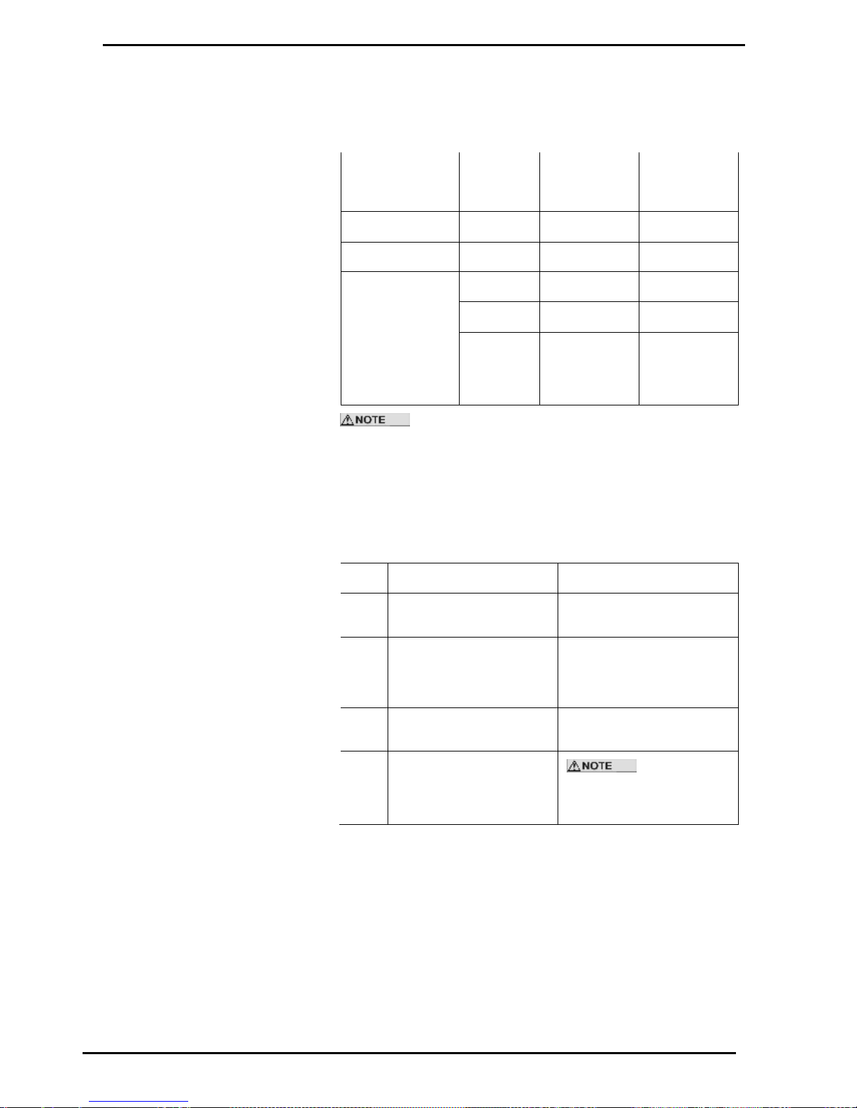
Display (Litres) Resolution
For standard dispenser/pumps, high flow dispenser/pumps & bulk metering,
different resolutions are often required:
Display
Resolution
Sr setting
on k factor
switch
Litres Display
resolution
Max
presetable or
fill amount
Standard (default)
0.000
0.00
970 L
Hi-Flow
0.00
0.00
9700 L
Bulk-metering
0.0
00000.0
0
000000
000000[0]
[0] is not
displayed
As well as displaying the decimal point, a full colon will show
on the display after 'power on', until the first transaction is started (i.e. the
display shows „:0.0‟ until the first new transaction begins).
The display resolution does not affect the price display, which will always
display to a resolution of 0.01 dollars.
Setting the Display Resolution
Refer to C4000 Set-Up K Factor Switch Settings (see page 21)
Step
ACTION
RESULT
1
Ensure that the nozzles are
hung up
Dispenser in idle state
2
Press and release the „K‟
Factor switch continuously
until the Litres resolution is
displayed
The price display indicates „Sr‟
and the Litres Resolution is
displayed as “0.00” (standard
resolution on 5-digit display)
3
Press and hold the „K‟ factor
switch.
The decimal point will begin to
move.
4
When the resolution
(decimal point) is correct,
release the „K‟ Factor
switch.
The C4000 will
reset itself if the „K‟ factor
switch is left for more than 10
seconds.
Page 27

Set-up Modes
Solenoid Delay
Compac Industries Ltd.
Page 27
www.compac.co.nz
Solenoid Delay
The Solenoid Delay was installed in the program to enable the "delay"
between the submersible pump operating and the dispenser solenoids
operating to be controlled on initial start-up. This setting should only be set
on dispensers.
This setting should never be set more than 4-6 seconds. Its main purpose
is to allow the leak detector on the submersible pump to carry out its leak
test.
The default setting is 'd0000‟ (i.e., no delay). All dispensers with a selfcontained pump should be left at the default setting.
Setting the Solenoid Delay
Refer to C4000 Set-Up K Factor Switch Settings (see page 21). While
setting this value, the price display will indicate „Sd‟ and the volume display
will indicate „dXXXX‟ where X equals one second.
Page 28

Pre-Set Cut-Off
Set-up Modes
Compac Industries Ltd.
Page 28
www.compac.co.nz
Pre-Set Cut-Off
Prior to the dispenser reaching its preset amount, the solenoids are
switched to give a low flow rate. The “preset cut-off” sets the amount (in
litres), prior to the preset amount being attained, at which the solenoids will
switch to a low flow rate.
With the value set to 0.00, the default values are used. These are:
LPG 0.75
Oil 0.05
Other products 0.32
The Preset Cut-off is calculated as follows:
[Price per Litre] X [over-run (displayed as a dollar value)] + default value as
above.
Example:
Price per Litre = $0.96
Dollar amount of fuel required = $20.00
After delivery price display shows: $20.01 ($0.01 is the over-run dollar
value)
New preset = (0.96 x 0.01) + 0.32 (Other Products) = 0.3296
0.3296 rounded up = 0.33
New preset cut-off to be entered is 0.33.
Setting the Pre-Set Cut-Off
Refer to C4000 Set-Up K Factor Switch Settings (see page 21) The Price
display shows 'PCut' and the volume display shows 'PCX.XX'. The range is
from 0.01 to 9.99 litres.
Further Settings Available on the 'K' Factor Switch
The following configurations (K-Factor) switch settings are only available for
CNG dispensers, LPG dispensers, or bulk meter registers. As they are
reasonably uncommon, they have not been included in sequence with the
four more common settings.
These 'uncommon' settings are:
Density Factor 'dSF' - CNG (needs appropriate software)
Temperature'E'- LPG (with compensation) – Bulkmeter
ACV Valve Flow rate 'FLO' - Bulkmeter
L Cut 'L' - Bulkmeter
H Cut'H' - Bulkmeter
F Cut 'F' - Bulkmeter
Specific Density Calibration 'LP6' - LPG (with compensation and with
densometer).
Page 29

Set-up Modes
Further Settings Available on the 'K' Factor Switch
Compac Industries Ltd.
Page 29
www.compac.co.nz
Product Density Factor
Setting the Product Density
Factor
Refer to C4000 Set-Up K Factor Switch Settings (see page 21) While
setting the Product density factor, the price display shows 'dSF' („dFb‟ for
side “B”) and the volume display shows 'X.XXXX'.
Specific Density (With a densometer)
This setting is only available for LPG dispensers with a densometer and
set-up for LPG with temperature compensation (configuration code =
7xx5x). This is not available in other modes.
For Bulkmeter modes (Sr=0) and LPG dispensers with
temperature compensation but without a densometer (configuration code =
5xx5x), the density must be set at the dispenser.
The specific density of the LPG is measured to allow the C4000 to
accurately convert the amount of LPG dispensed to the LPG dispensed @
15ºC. The specific density of the product is measured using the Compac
densometer and is corrected to specific density at 15ºC. It is always
displayed in units of kg/m3.
Page 30

Further Settings Available on the 'K' Factor Switch
Set-up Modes
Compac Industries Ltd.
Page 30
www.compac.co.nz
Calibrating Specific Density (Densometer)
To accurately calibrate the densometer the temperature reading must be
correct. Always calibrate the temperature before calibrating the density.
Using the ‘K’ Factor switch to calibrate the densometer:
Step
ACTION
RESULT
1
Ensure that the nozzles are
hung up
Dispenser in idle state
2
Press and release the „K‟
Factor switch, in quick
succession, until „LP6‟ is
displayed in the price
display.
The volume display indicates
„00000‟.
3
Press and hold the „K‟ factor
switch.
A digit, of the volume display,
will begin to increment.
4
When the digit is correct,
release the „K‟ Factor
switch.
5
Repeat steps 3 & 4 until the
volume display reads 1.
The volume display indicates
00001.
5
Press and release the „K‟
Factor switch, in quick
succession, until „den‟ is
displayed in the price
display.
The LPG pump will start and
the volume display indicates
the specific density @ 15ºC.
6
Press and hold the „K‟ factor
switch.
A digit, of the displayed
setting, will begin to
increment.
7
When the digit is correct,
release the „K‟ Factor
switch.
8
Repeat steps 6 & 7 until the
volume display reads the
correct density as measured
by a hydrometer and
corrected to 15ºC.
The volume display indicates
the correct specific density.
The C4000 will reset itself if the „K‟ factor switch is left for
more than 10 seconds.
Pressure does have a small effect on density so you will notice that the
LPG pump will run while the density is being calibrated. This ensures that
the density is always being measured and calibrated at approximately the
same pressure.
Page 31

Set-up Modes
Further Settings Available on the 'K' Factor Switch
Compac Industries Ltd.
Page 31
www.compac.co.nz
Temperature Calibration
Only available for LPG and Bulk-meter modes and only if the Temperature
Compensation PCB is installed and temperature compensation configured
as detailed in Section 0
To set the temperature, place the probe in product of a known temperature.
Allow 10 minutes for the probe temperature to stabilise, then adjust the
temperature setting in the register 'XXX.X' to the known temperature value.
To check operation of the probe, press the 'K' factor switch to observe E in
the Price display and „XXX.X' in the volume display. Allow the display to
return to normal. Warm the probe and recheck the K-Factor switch
temperature setting. The new temperature should be displayed.
The temperature is not updated while it is being displayed.
Setting the Temperature
Refer to K Factor Switch Settings (see page 21) While setting the
temperature, the price display shows E and the volume display shows
'XX.X'. The temperature is displayed in degrees Celsius.
ACV Valve Flow Rate
This is only available in Bulk Meter mode where the ACV Valve has
'Compac Designed' controls. The Configuration code must be set-up for
“Compac flow modulation” (4th digit set to 2. Refer to Configuration Code
(see page 16) )
Setting ACV Valve Flowrate
Refer to K Factor Switch Settings (see page 21) While setting the ACV
Valve flowrate, the price display shows 'FLO' and the volume display shows
'rXXXX'. The desired flowrate for the system must be entered in litres per
minute.
L-Cut
This is only available in Bulk-meter mode.
This value is similar to the preset cut-off used in a standard dispenser. Prior
to the delivery reaching its preset amount, the solenoids are switched to
give a low flowrate. The “L-Cut” sets the amount (in litres), prior to the
preset amount being attained, at which the solenoids will switch to a low
flow rate.
Setting L-Cut
Refer to K Factor Switch Settings (see page 21) While setting the “L-Cut”,
the price display shows 'LCUT' and the volume display shows 'LXXXX'.
Page 32

Further Settings Available on the 'K' Factor Switch
Set-up Modes
Compac Industries Ltd.
Page 32
www.compac.co.nz
H-Cut
This is only available in Bulk Meter mode.
This value is the desired cut-off point to half flow (in litres) for the system.
The “H-Cut” sets the amount (in litres), prior to the preset amount being
attained, at which the flow rate of the system will be halved.
Setting H-Cut
Refer to K Factor Switch Settings (see page 21) While setting the “H-Cut”,
the price display shows 'HCUt' and the volume display shows 'HXXXX'.
F-Cut
This is only available in Bulk Meter mode.
This is the final cut-off point to pre-set (in litres) 'FXXX.X' for the system.
Setting F-Cut
Refer to K Factor Switch Settings (see page 21) While setting the “F-Cut”,
the price display shows 'FCut' and the volume display shows 'FXXXX'.
Page 33

Set-up Modes
Parameter Switch
Compac Industries Ltd.
Page 33
www.compac.co.nz
Parameter Switch
Refer to Figure 1 Main Features C4000 (see page 12) to find the location of
the parameter switch.
The Parameter switch has several functions including:
Identifying the software programme version number, 'P XX'
Setting the dispenser/pump price, 'Pr' or 'P'
Setting the product density, 'dEn' (Bulkmeter Registers and LPG with
compensation but without a densometer only)
Setting the pump/dispenser number, 'Pn'
Displaying End of Sale indications
Setting the dispenser sequencing rate, 'SE9' (CNG only)
Validating and invalidating cards/pins/keys, 'Y' or 'n' (Comcard,
Compin, or CWIDKey pumps/dispensers only)
Setting the card access code, 'A' (Comcard or CWIDKey
pumps/dispensers only)
Conducting Display Segment Test
Parameter Switch Settings - all must be set, but the order of
the set-up is not critical.
Program Version Number
To determine program version number, hang up the nozzle, then push the
parameter switch once. The system enters a diagnostic mode whereby it
displays the program type data and performs a display segment test. When
showing program data, the display panel shows 'PXX' where 'XX' is the
program version number.
Page 34
Parameter Switch
Set-up Modes
Compac Industries Ltd.
Page 34
www.compac.co.nz
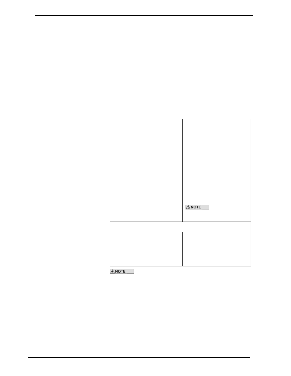
Setting the Price per Litre
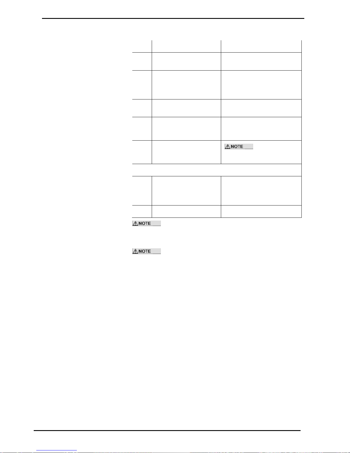
The C4000 processor board can be set for five hose configurations:
1. Single (e.g. one C4000 controls one hose)
2. Dual (e.g. one C4000 controls two hoses)
3. Quad (e.g. one C4000 controls four hoses but only two (one per side)
can operate at any time)
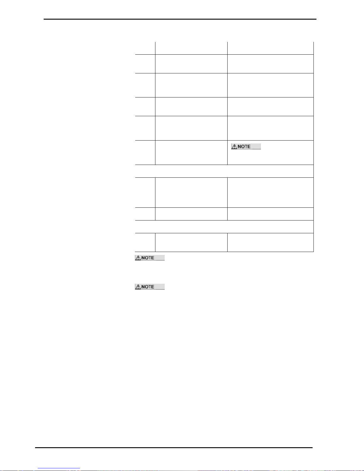
4. True Quad (e.g. one C4000 controls four hoses which can all operate
at once)
5. Six (e.g. one C4000 controls six hoses but only two can operate at
once)
The following charts are to be used to set the price.
Setting Price for a Single or Dual Hose Configuration
Step
ACTION
RESULT
1
Ensure that the nozzle is
hung up
Dispenser in idle state
2
Press and Hold the
Parameter switch operated
until the “Price per litre” is
displayed.
The Price for side „A‟ is displayed
as „PX.XXX‟ and „Pr‟ is displayed
on the price display.
3
Press and hold the
Parameter switch.
A digit, of the displayed „Price per
litre‟, will begin to increment.
4
When the digit is correct,
release the Parameter
switch.
5 Repeat steps 3 and 4 for
each digit of the „Price per
litre‟.
The C4000 will
reset itself if the Parameter switch
is left for more than 60 seconds.
Continue for Dual hose units
6
Press and release the
Parameter switch 8 or
more times in quick
succession
The „Price per litre‟ for side “B” is
displayed as „bX.XXX‟ and „Pr” is
displayed on the price display.
7
Repeat steps 3 to 5 above.
If a Compac Central Controller, EFTPEC, Task forecourt controller, or
Compac Commander is used, the price must be set to zero (0) at the
pump/dispenser. The price can then be set at the Controller. This applies
to all configuration display options.
The dispenser/pump will stop when the dollar amount reaches: $999.99
(high-flow $9999.9) or the litre amount reaches 999.99l (high-flow 9999.9l)
whichever occurs first.
The dispenser will not allow the price/litre to be altered during a delivery
When the price/litre is altered, the dispenser will display the new price/litre
for at least 5 seconds before allowing a new transaction to begin.
Page 35
Set-up Modes
Parameter Switch
Compac Industries Ltd.
Page 35
www.compac.co.nz
Setting the Price for Quad (four) Hose Configuration
Step
ACTION
RESULT
1
Ensure that the nozzles are
hung up
Dispenser in idle state
2
Press and Hold the
Parameter switch operated
until the “Price per litre” is
displayed.
The Price for hose 1 is displayed
as „PX.XXX‟ and „Pr1‟ is
displayed on the price display.
3
Press and hold the
Parameter switch.
A digit, of the displayed „Price per
litre‟, will begin to increment.
4
When the digit is correct,
release the Parameter
switch.
5
Repeat steps 3 and 4 for
each digit of the „Price per
litre‟.
The C4000 will
reset itself if the Parameter switch
is left for more than 60 seconds.
Continue for other hoses
6
Press and release the
Parameter switch 8 or more
times in quick succession
The „Price per litre‟ for the next
hose is displayed as „PX.XXX‟.
„Pr2‟, Pr3‟ or „Pr4‟ is displayed on
the price display.
7
Repeat steps 3 to 5 above.
If a Compac Central Controller, EFTPEC, Task forecourt
controller, or Compac Commander is used, the price must be set to zero (0) at
the pump/dispenser. The price can then be set at the Controller. This applies
to all configuration display options.
The dispenser/pump will stop when the dollar amount reaches:
$999.99 (high-flow $9999.9) or the litre amount reaches 999.99l (high-flow
9999.9l) whichever occurs first.
Page 36
Parameter Switch
Set-up Modes
Compac Industries Ltd.
Page 36
www.compac.co.nz
Setting the Price for True Multi-Product Configuration
Step
ACTION
RESULT
1
Ensure that the nozzles are
hung up
Dispenser in idle state
2
Press and Hold the „Side A‟
Parameter switch until the
“Price per litre” is displayed.
The Price for hose 1 side „A‟ is
displayed as „PX.XXX‟ and „Pr1‟ is
displayed on the price display.
3
Press and hold the
Parameter switch.
A digit, of the displayed „Price per
litre‟, will begin to increment.
4
When the digit is correct,
release the Parameter
switch.
5
Repeat steps 3 and 4 for
each digit of the „Price per
litre‟.
The C4000 will reset
itself if the Parameter switch is left
for more than 60 seconds.
Continue for each hose
6
Press and release the
Parameter switch 8 or more
times in quick succession
The „Price per litre‟ for the next
hose on side „A‟ is displayed as
„PX.XXX‟. „Pr2‟ or „Pr3‟ is
displayed on the price display.
7
Repeat steps 3 to 5 above.
Continue for side “B”
8
Repeat steps 1 to 7 for side
“B”
If a Compac Central Controller, EFTPEC, Task forecourt
controller, or Compac Commander is used, the price must be set to zero (0) at
the pump/dispenser. The price can then be set at the Controller. This applies to
all configuration display options.
The dispenser/pump will stop when the dollar amount reaches:
$999.99 (high-flow $9999.9) or the litre amount reaches 999.99l (high-flow
9999.9l) whichever occurs first.
Page 37
Set-up Modes
Parameter Switch
Compac Industries Ltd.
Page 37
www.compac.co.nz
Setting the Product Density
Only available in Bulkmeter mode (when Sr = 0) or LPG with compensation
but without a densometer (configuration code of 5xx5x).
The product density (kg/m3) must be set. In bulkmeter mode this can be
done either at the register (for 'stand-alone' C4000 Heads), or at the central
controller. For controller sites the density entered at the register must be
zero to allow the 'controller set' density to override. On LPG dispensers, the
product density (kg/m3) is set at the dispenser.
If the C4000 is in Bulkmeter mode or set-up for LPG with temperature
compensation but without a densometer (Configuration code = 5xx5x) then
the density can be set using the parameter switch.
This is not available in other modes.
While setting the Specific Density, the price display shows 'dEn' and the
volume display shows 'XXX.X' the density (Kg/m3) @ 15ºC.
Setting Specific Density (Settable density)
Step
ACTION
RESULT
1
Ensure that the nozzles are
hung up
Dispenser in idle state
2
Press and release the
Parameter switch, in quick
succession until the density is
displayed.
The price display (top) shows
„dEn‟ and the volume display
shows the density „XXX.X‟ in
kg/m3 @ 15ºC
3
Press and hold the Parameter
switch.
A digit, of the density, will begin
to increment.
4
When the digit is correct,
release the Parameter switch.
5
Repeat steps 3 and 4 for each
digit of the density.
The C4000 will
reset itself if the Parameter
switch is left for more than 60
seconds.
The same density is used for all hoses on a multi-hose
dispenser.
Setting the Dispenser/Pump Number
Press and release the Parameter switch nine (9) or more times and the
message 'Pn' will appear on the Price (top) display. The number displayed
in the volume (middle) display is the pump number. Press and hold the
parameter switch and the processor will roll the displayed number until the
switch is released. The value of the displayed number will then be stored
as the pump/dispenser number.
Displaying the End of Sale Indications
Press and release the Parameter switch nine (9) or more times and the
message 'Pn' will appear on the „Price‟ (top) display. The number displayed
in the „volume‟ (middle) display is the pump number and the number
displayed in the „price per litre‟ (bottom) display is the „end of sale‟ indicator.
Page 38

Parameter Switch
Set-up Modes
Compac Industries Ltd.
Page 38
www.compac.co.nz
Setting the Sequencing Rate
This is only available for CNG Dispensers.
Needs appropriate software.
The rate of sequencing between pressure banks for the CNG dispensers is
done on a percentage basis. There are three percentage settings to choose
from:
Fast, 'FAS' switching to the next higher-pressure bank occurs at 45% of the
full flow rate.
Normal, 'nOr' switching to the next higher-pressure bank occurs at 35% of
the full flow rate.
Slow, 'SLO' switching to the next higher-pressure bank occurs at 25% of
the full flow rate.
To set the Sequencing rate
Press and release the Parameter switch seventeen (17) or more times,
without holding it depressed for long enough to change any digits, until
'SE9','XXX' appears. Hold the switch depressed until the correct
sequencing rate is displayed, then release.
The displayed sequencing rate is now selected and operation of the
dispenser will be affected immediately. The displays will reset after a ten
(10) second timeout.
Validating/Invalidating Cards Pins or Keys
This is only available on Comcard Basic, Compin Basic, or CWIDKey Basic
systems (i.e. 'b' setting digit 3 = 2.
1. Ensure that the nozzle is hung up. Press the Parameter switch 16 or
more times without holding the switch depressed long enough for any
digits to change or for the system to enter the pump number setting
mode. The switch must be depressed for two seconds or longer for the
latter to occur. Card status information will then appear on the litre
display panel. The left of the display panel shows a 'Y' or 'n' where 'Y'
is Valid & 'n' is Invalid; the right of the panel shows the two-digit card,
pin, or key number.
2. The desired card/pin/key number can be selected by changing each
digit using the usual press/hold/release method with the Parameter
switch. When the figure on the left side of the display panel is selected,
it can be changed from 'n' to 'Y' to 'n' etc. by holding the Parameter
switch depressed. Therefore, the respective card status can be
selected by releasing the switch when the desired card status symbol is
displayed.
To change multiple cards repeat the above process for the appropriate card
numbers. The display will return to normal operation after the Parameter
switch is not operated for ten (10) seconds.
On older systems Card 99 is the Service card and was
universally accepted by all Comcard card-readers.
Page 39

Set-up Modes
Parameter Switch
Compac Industries Ltd.
Page 39
www.compac.co.nz
Setting the Access Code
This is only available on Comcard or CWIDKey Basic systems (i.e. 'b'
setting digit 3 = 2.
Compin does not require any Access Code.
Depress the Parameter switch 24 or more times, without holding it
depressed long enough to change any digits, until 'AXXXX' appears on the
display. This number is different for each Compac Card/Key System, which
ensures that the cards/keys for any one system cannot be used on any
other systems.
The access code can be changed by the usual press/hold/release method
using the Parameter switch.
Access Code will only need to be changed to prevent an
existing Card/Key System being used, or to allow a new card system to be
issued in the case of several lost or stolen cards. Refer also to Displaying
and Printing Totals (see page 41)
Page 40

Printer Set-up
Set-up Modes
Compac Industries Ltd.
Page 40
www.compac.co.nz
Printer Set-up
Comcard Compin & CWIDKey Basic Systems
The printer used is the Star printer, with modifications. Recessed in the left
side of the printer are two (2) banks of dipswitches. The switches are UP
when set to ON (see diagram below).
Figure 4. Star Printer Dipswitch Settings
The cable used to connect the printer to the pump/dispenser is supplied by
Compac. One end has a 25 way 'D' connector, with an interface PCB within
the „D‟ connector housing.
The other end is a four pin AMP connector where:
Pin 1 - Red
Pin 4 - Black
Printer Self Test
To carry out the self-test, press and hold down the FEED and ON LINE
buttons while switching the power on.
Page 41

Set-up Modes
Displaying and Printing Totals
Compac Industries Ltd.
Page 41
www.compac.co.nz
Displaying and Printing Totals
General
To display litre and dollar totals for any single hose on a pump/dispenser,
make sure all nozzles are hung up. Then, for pumps/dispensers:
With Preset: Press either the Cancel or the Fill button, on the hoses'
respective Preset, five or more times and the totals will appear on the
displays.
Without Preset: Remove the nozzle from its holster and hold the nozzle
switch in for five seconds. Then press the nozzle switch rapidly five or
more times - ensuring that the switch 'clicks' each time. The five digit
whole dollar and litre totals will then be shown on the display for ten
seconds.
Scrolling Tote Option
This is only available on Comcard, Compin, and CWIDKey Basic systems
(i.e. 'b' setting digit 3 = 2)
To access this option the 'b' setting digit 1 must be set to one.
Pump/Dispenser totals are accessed as above, then after displaying the
pump/dispenser total for ten seconds the card/pin/key number and
card/pin/key total will appear. The display will flash for 10 seconds and then
go to the next card/pin/key. All cards/pins/keys with non-zero totals and all
valid cards/pins/keys will be 'scrolled'.
Using a Totals Only - Report
Printer
This is only available on Comcard, Compin, or CWIDKey Basic systems
(i.e. 'b' setting digit 3 = 2.)
Plug the two core cable from the printer into the four pin plug (Red Comms
- Pin 1, Black Comms - Pin 4) on the side of the pump/dispenser. Power up
the printer and make sure it is 'ON LINE'. Then depress the nozzle switch
five or more times - ensuring that the switch 'clicks' each time. The printout
will contain all cards/pins with non-zero totals and all valid cards/pins/keys.
Card/pin/key status is also displayed on this printout.
The printer may also be permanently wired to the C4000 comms. If the
printer is left with the power on and on-line, it will then act as an 'audit trail
printer'. It will then print out the card/pin/key number, litres dispensed and
the total in dollars, at the end of each fill.
All totals mentioned above are non-resettable totals (the only
way they can be cleared is by replacing the C4000 memory IC 'chip').
The displays are only capable of displaying five-digit whole litre totals
(maximum of 99999), but the C4000 memory stores seven digit whole litre
totals (maximum of 9999999.99) for printing
Receipt Printer
With Central Controller and Futra systems, it is possible to install a receipt
printer either at the pump/dispenser, or at the Central Controller.
The receipt printout includes the following information: Site Number, Pump
Number, Card Number, Reference Number, Date, Time, Product, Litres,
Dollars, Dollars per litre, Odometer Reading (if prompted).
Page 42

Displaying and Printing Totals
Set-up Modes
Compac Industries Ltd.
Page 42
www.compac.co.nz
Printer Housed at the Pump/Dispenser (Card King)
This is only permissible in 'Type B' fuel pumps/dispensers (as defined by
AS2229-1) or in pumps/dispensers used in applications where less
stringent requirements are set. This is because the printer is not an
intrinsically safe device and must have access to the pump/dispenser
exterior for the 'printer paper slot'.
The printer receives the data for printing and cutter operation from the
C4000 microprocessor PCB, via an interface PCB (CI125) which also
provides the printer with a 12V power supply. The interface PCB provides
'opto-isolation' between the C4000 intrinsically safe circuitry and the
'unsafe' printer circuitry, for the printer driver signal.
This Receipt Printer option is only available for C4000 microprocessors
controlling one hose pumps/dispensers, or for C4000s which are set-up in
'True Multi' configuration. A PIN pad must also be connected to the C4000
and the third digit of the Configuration Code must be set to '1' or '3'
On a pump/dispenser set-up with a receipt printer, a receipt is obtained
as follows:
1. Authorise the transaction as for a normal fill until the PIN pad
display reads “REQUIRE RECEIPT YES OR NO”
2. Press 'YES'
3. The display will read “TAKE FUEL”
Continue the fill as per normal and at the completion of the fill, a receipt will
print automatically.”
If the nozzle is still in holster:
1. Pin pad reads: “LOAD PRESET”
2. Press: “ENTER”
If the nozzle is lifted:
Pin pad reads: “TAKE FUEL”
If the Receipt Printer is not operational (e.g. out of paper),
then when the PIN pad displays: “PASS CARD” it will also display:
“NO RECEIPT”
Electrical Connection
The data cabling for the printer connects to the C4000 intrinsically safe
terminals at connector J14. The other end of these wires connects to
connector CON5 on the Interface PCB (CI125).
The 220-240V supply connection on the Interface PCB is at connector
CON1.
Power and data connections to the printer and cutter are from CON2 &
CON3 on the Interface PCB.
Receipt Printer Connected to the Central Controller
Where a Central Controller is installed on site, it is possible to connect a
Receipt Printer to the Central Controller Comms Port 3 to obtain printouts.
Two operational options can be configured at the pump/dispenser C4000
when the Receipt Printer is connected like this:
1. If a Receipt Printer is connected to the Controller and left „ON LINE‟,
then by setting the third digit of the Configuration Code to '0' or '2' (for
standard or Secure PIN pad operation respectively), a receipt will be
printed after each transaction. This should be the set-up chosen when
a receipt is always required or when the pump/dispenser does not have
Page 43

Set-up Modes
Basic Systems (Comcard Compin & CWIDKey)
Compac Industries Ltd.
Page 43
www.compac.co.nz
a PIN-pad installed.
2. If the pump/dispenser has a PIN pad connected, then it can be
configured to display a receipt prompt as part of the transaction
authorisation process. This prompt would be the same as for a
pump/dispenser with a Receipt Printer connected to the C4000
(detailed on the previous page). To select this option the third digit of
the Configuration Code for the C4000 should be set to '4' or '5',
depending upon whether a standard or Secure PIN pad is installed on
the pump/dispenser.
Electrical connection of the Receipt Printer in this mode is covered in the
Central Controller Service Manual.
Basic Systems (Comcard Compin & CWIDKey)
For these systems to operate the 'b' setting digit 3 must be set to two. Refer
'b' Settings (see page 18). In this mode of operation the 'C4000 Head'
operates as a totally self-contained system operating independently of the
central controller. The C4000 'Comms' circuitry, which is usually used for
communicating with a controller, is now used to run an audit trail and/or
receipt printer (Refer Printer Set-up (see page 40)). These systems can
have a maximum of 99 cards/pins/keys.
Comcard Basic
The Comcard Basic system uses magstrip cards to initiate a transaction.
These cards are encoded with an access number and a card number.
There can be only one access number per pump and the card numbers
must be in the range of 01 to 99.
In older Comcard basic systems, card number 99 was
reserved for servicing.
All Comcard Basic systems will have a card reader attached to the front or
side of the pump/dispenser.
Usually the card number is printed or embossed on the card. If this is not
the case the card can be identified in the same manner as the CWIDKey
identification procedure.
Compin Basic
The Compin Basic system simply uses a two digit PIN number to initiate a
transaction. This operates in the same manner as the Comcard Basic
system except that digit 4 of the configuration code (refer Setting the
Configuration Code (see page 16) ) must be set to two (2). Also there is no
access number required. The PIN number acts as the card number and all
of the same totals are available.
CWIDKey Basic
The CWIDKey Basic system uses a CWID (Compac wireless Identifier) key
to initiate a transaction. These systems have a CWID aerial placed at the
nozzle or on the pump/dispenser.
Where the aerial is placed at the nozzle, the CWID tags must be mounted
in close proximity to the filling spout. If the aerial is on the dispenser the
customer must hold the CWID tag close to the reader panel on the
dispenser. The CWID tags are a small (approx. 32mm x 5mm diameter)
sealed tag. They do not require batteries.
The CWIDKey Basic system operates in the same manner as the Comcard
Basic system except that digit 3 of the configuration code (refer Setting the
Configuration Code (see page 16) ) must be set to six (6). The CWID tags
Page 44

Basic Systems (Comcard Compin & CWIDKey)
Set-up Modes
Compac Industries Ltd.
Page 44
www.compac.co.nz
are encoded with an access code and a key number in the same way that a
comcard is encoded.
CWIDKey Number Identification.
When a valid key is presented to the dispenser the display will alternately
flash the key totals then the key number, until the nozzle is lifted. The key
number is displayed as "c xx" where xx is the keynumber. The access
number is never displayed.
If an invalid key with the correct access code is presented to the dispenser
the display will show "----" for one second then the key number for one
second.
If a key with an incorrect access code is presented to the dispenser then
the display will only show "----" for two seconds.
Page 45
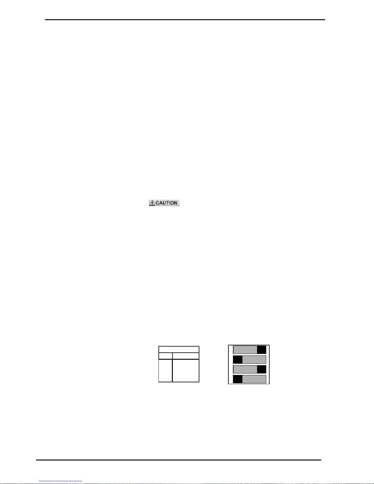
Electrical Wiring C4000
Basic Systems (Comcard Compin & CWIDKey)
Compac Industries Ltd.
Page 45
www.compac.co.nz
Electrical Wiring C4000
230 Volt wiring
Power for the C4000 'head' connects to the terminals marked Phase,
Neutral, & the Earth Stud.
Refer Connecting Mains Power and Communications (see page 10)
On the C4000 Power supply PCB, the incoming phase feeds the
microprocessor power supply through the fuse F2 (250mA) and feeds all
low current solid state relay circuits through the fuse F3 (1A).
Solenoids and motors are connected to the appropriate terminals.
Communications (Comms)
Wiring
Communication cables connect to the comms terminals marked Red and
Black.
Refer Connecting Mains Power and Communications (see page 10)
The Communications wiring is a 12 volt circuit and any
contact with mains will cause permanent damage.
The C4000 can communicate with the following Forecourt Controllers:
Micro M
Eftpec
Compac Central Controller
Task
Postec
Compac Commander
Comms DIP Switch settings
The Comms dipswitches are on the C4000 power supply PCB. Refer
Figure 7 Solid State Relays (Triacs) (see page 61)
ON
SW 3
4
3
2
1
1
2
3
4
Comm s D ipsw itches
Sw
Std C o m ms
ON
OFF
ON
OFF
Figure 9. Comms DIP Switch Settings
Standard Compac Comms (or PEC Comms)
Switch 1,3 ON
Switch 2,4 OFF
With Gilbarco consul interface
Switch 1,3 OFF
Page 46
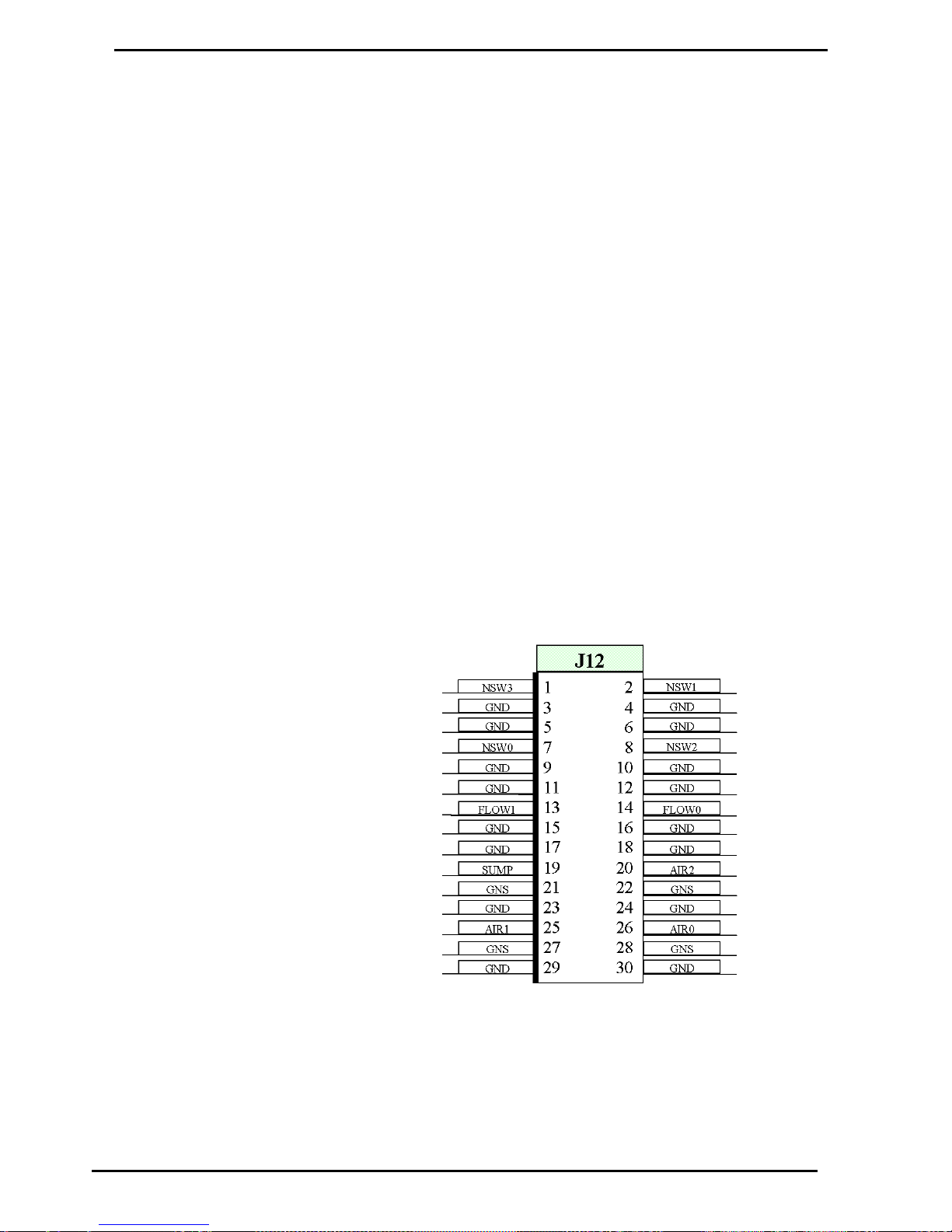
Basic Systems (Comcard Compin & CWIDKey)
Electrical Wiring C4000
Compac Industries Ltd.
Page 46
www.compac.co.nz
Switch 2,4 ON
C4000 Gilbarco Protocol
Converter
A Gilbarco interface board (CI143) plus any software version HIA29107
onwards (or HIU29107 for USA Gilbarco protocol) is required if the C4000
is to connect to a Gilbarco Consul. The Comms dipswitch settings (See
Figure 7 & Figure 9) must be set with switches 1& 3 OFF and switches 2 &
4 ON.
The Gilbarco interface board plugs onto the IS Power supply PCB in the
Flameproof box. The IS Cable must be setup to connect to the Gilbarco
interface board. The Comms still connects to the Red & Black terminals as
with the standard Comms.
Intrinsically Safe Wiring
The location of the various connectors are shown in Figure 1. Refer
Description C4000
Air Detector Cut-out Switch
The Air detector cut-out switch is required on any Bennett pump pumping
diesel or any Bennett pump pumping any product at more than 55 litres per
minute. This switch is a 'normally open' pressure-activated switch, which
closes when the pressure of the air venting from the pumping unit exceeds
a preset level. The closing of this switch disables the C4000's outputs,
ending the transaction in progress. The pump can be re-authorised and
another transaction can take place immediately after the pump stops,
without the need to de-power and re-power the electronics.
Figure 10. Connector J12 (Nozzle, Air, Sump, and Flow switches)
Nozzle Switch(es)
Page 47
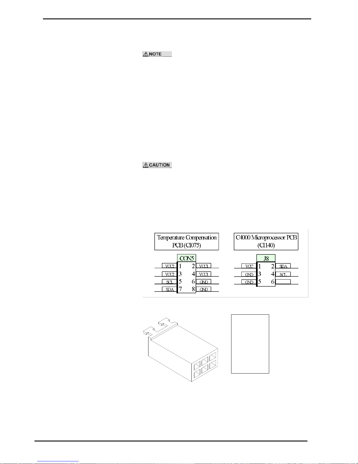
Electrical Wiring C4000
Basic Systems (Comcard Compin & CWIDKey)
Compac Industries Ltd.
Page 47
www.compac.co.nz
The nozzle switch leads plug in between 'NSWx' and 'GND' (see Figure 10
above). When the nozzle is lifted, the nozzles switch closes and the C4000
initiates a transaction.
Diagnostic LED will flash rapidly when any nozzle is lifted
regardless of hose configuration.
Sump Switch
The Sump Switch is a float switch located in a sump at the bottom of the
dispenser. If the dispenser pipe work leaks, then the tray fills with product,
thereby activating the switch.
If the switch closes, then the dispenser stops and the litres display reads
"SunP".
The Sump Switch is wired into the SUMP and GNS terminals on the J12
connector (see Figure 10). If there is more than one head in the dispenser
(e.g. MHD6), then the sump switch is to be connected to both heads.
Ensure that the SUMP terminals are joined and the GNS terminals are
joined.
DO NOT connect the GNS terminal on one head to the
SUMP terminal on the other.
Temperature Pressure
Compensation PCB (CI075)
The Temperature Compensation PCB is mounted in a separate enclosure
and is connected to the C4000 Microprocessor via a four wire cable. The
PCB Pin headers and cable connectors are shown below.
Figure 11. Temperature Compensation Connectors.
1
1 – Red
2 – Green
3 – S creen
4 – Whit e
5 – Black
6
3
5
2
4
6
Figure 12. Connector to C4000 Microprocessor PCB (J8)
Page 48
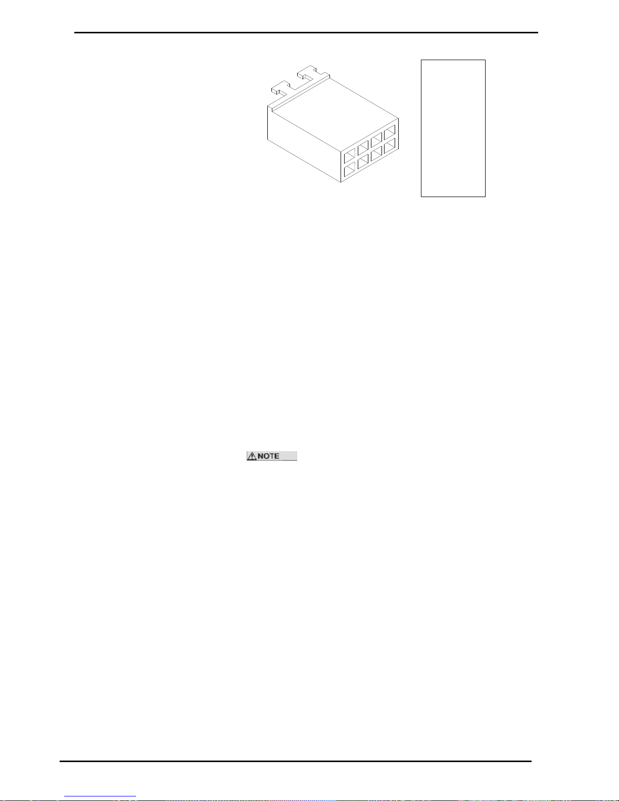
Basic Systems (Comcard Compin & CWIDKey)
Electrical Wiring C4000
Compac Industries Ltd.
Page 48
www.compac.co.nz
1
1 – Loop
2 – Loop
3
4 – Red
5 – Whit e
6 – Black
7 – Green
8
357
2
4
6
8
Figure 13. Connector to Temperature Compensation PCB (CON5)
The pressure sensors and temperature sensors supplied by Compac have
the appropriate plug to be able to plug them into the Temperature
Compensation PCB.
Display Backlighting
The backlighting PCB's consist of several red backlighting LED's and the
PCB's are mounted on stand-offs behind the displays.
The backlighting PCB's are supplied from the C4000 'Backlight' plug (J17).
This is an intrinsically safe supply.
Card-readers
The C4000 can drive two Card readers. They plug into the C4000
Microprocessor PCB (Connectors J15 & J16). The Card readers can be a
'Track 1' or 'Track 2' type card-reader. The 'track' number indicates the
track on the magnetic strip of the card which will be read.
Compac Systems will be either a TK1 or a TK2 type, and will
never be used both together. This is because information is coded, and
therefore gathered, from either the first track or the second track of the
coded magnetic strip.
Page 49
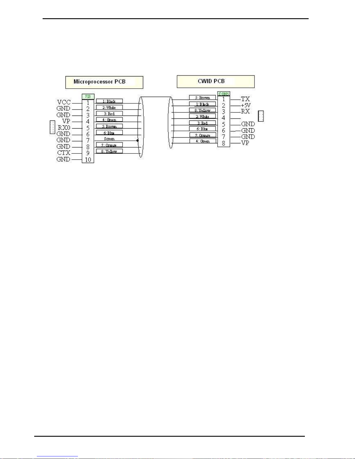
Electrical Wiring C4000
Compac Wireless Transceiver
Compac Industries Ltd.
Page 49
www.compac.co.nz
Compac Wireless Transceiver
The CWID PCB is mounted in a separate enclosure. Connector 'CON5' on
the CWID PCB (see below) connects to J13 on the C4000 Microprocessor
PCB (Refer Description C4000) with an eight wire cable (see below)
Figure 1: CWID (CON5) to microprocessor (J13) cable
Page 50
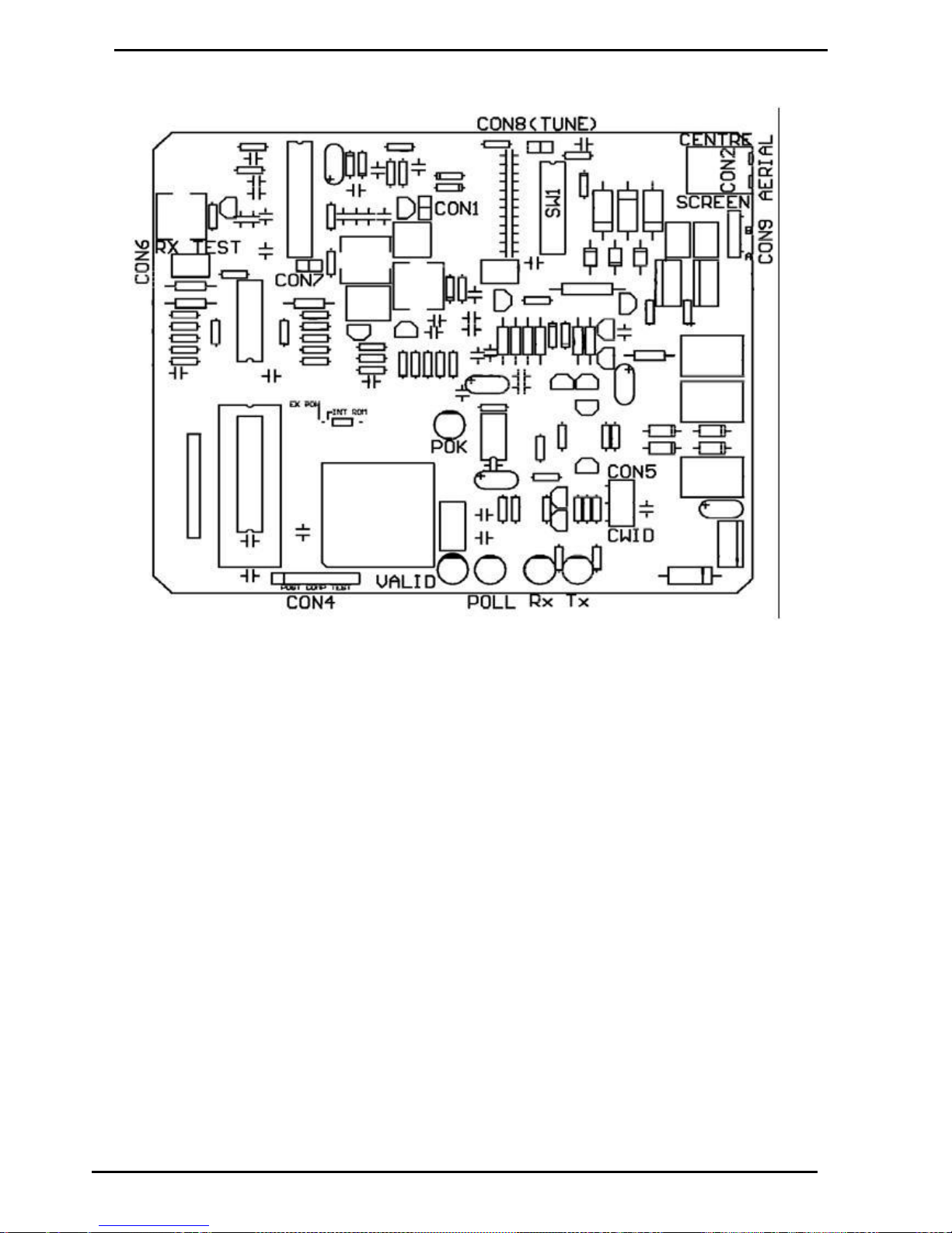
Compac Wireless Transceiver
Electrical Wiring C4000
Compac Industries Ltd.
Page 50
www.compac.co.nz
Figure 2: CWID (CI 101 issue D) PCB
Page 51

Electrical Wiring C4000
Compac Wireless Transceiver
Compac Industries Ltd.
Page 51
www.compac.co.nz
Tuning the Aerial
Whenever the CWID PCB is changed, the aerial will need to be tuned. For
locations of the connectors, refer to the picture in CWID Interface Board
Replacement.
1. Connect a Multimeter (set to Volts) to CON8.
2. Place a shorting link across pins 2 & 3 of CON4. The poll LED will flash
slower, indicating "Tuning Mode"
3. Using the dipswitches (SW1), adjust the capacitance to obtain the
maximum voltage at CON8. Each dipswitch adds a capacitor to the
tuned circuit. The DIP switches 1 to 5 are primary capacitors while 6 to
8 are fine tuning capacitors.
4. Use the following technique:
5. Turn on Switch 1 and measure voltage, turn on switch 8 and see if
voltage rises or falls. If it rises, turn off 8 and turn on switch 2.
6. Continue this procedure for switches 3,4 and 5 until you get a voltage
drop.
7. If the voltage drop occurs at switch 2,3,4 or 5 then return to the
previous switch and add switches 6,7 and 8 until the voltage drops.
When the drop occurs, revert to the previous switch.
8. If there is no voltage drop as switches 6, 7 and 8 are added, compare
this voltage to the voltage achieved at the next primary switch with 6, 7
and 8 turned off.
9. If you can't get a voltage drop when the fine tuning switches are used,
use the chart below to calculate a capacitance figure between the
switch combination achieved above. For example:If 1+2+6+7+8 (7.3
nF) obtains a higher voltage than 1+2+3 (8.33nF) then try 1+2+5 (7.33
nF) if the voltage reading is higher than the two previous combinations,
switch on 8 then 7 then 6 until you get a drop. If no drop is measured
then try 1+2+4(7.66 nF). Keep working with combinations until you get
the voltage drop when one of the fine tuning switches is added or you
have run out of combinations. Always use the setting that achieves the
highest voltage.
10. If the voltage drop occurs at step 5, turn off switch 1 and turn on
switches 2,3,4 and 5 then test for voltage drop with switch 8. If voltage
drops then turn off switch 5, measure voltage and test again with switch
8. Continue with combinations until a voltage drop occurs when one of
the fine tuning capacitors is switched on.
11. Though the CWID aerial can work at lower voltages, the voltage
reading should be above 28 Volts.
12. Remove the shorting link fitted at 2 above.
13. Test the operation with a valid CWID key.
Dipswitch
(SW1)
Capacitance
(nF)
Dipswitch
(SW1)
Capacitance
(nF)
1
4.7 5
0.33
2
2.3 6
0.1
3
1.33 7
0.1
4
0.66 8
0.1
Page 52
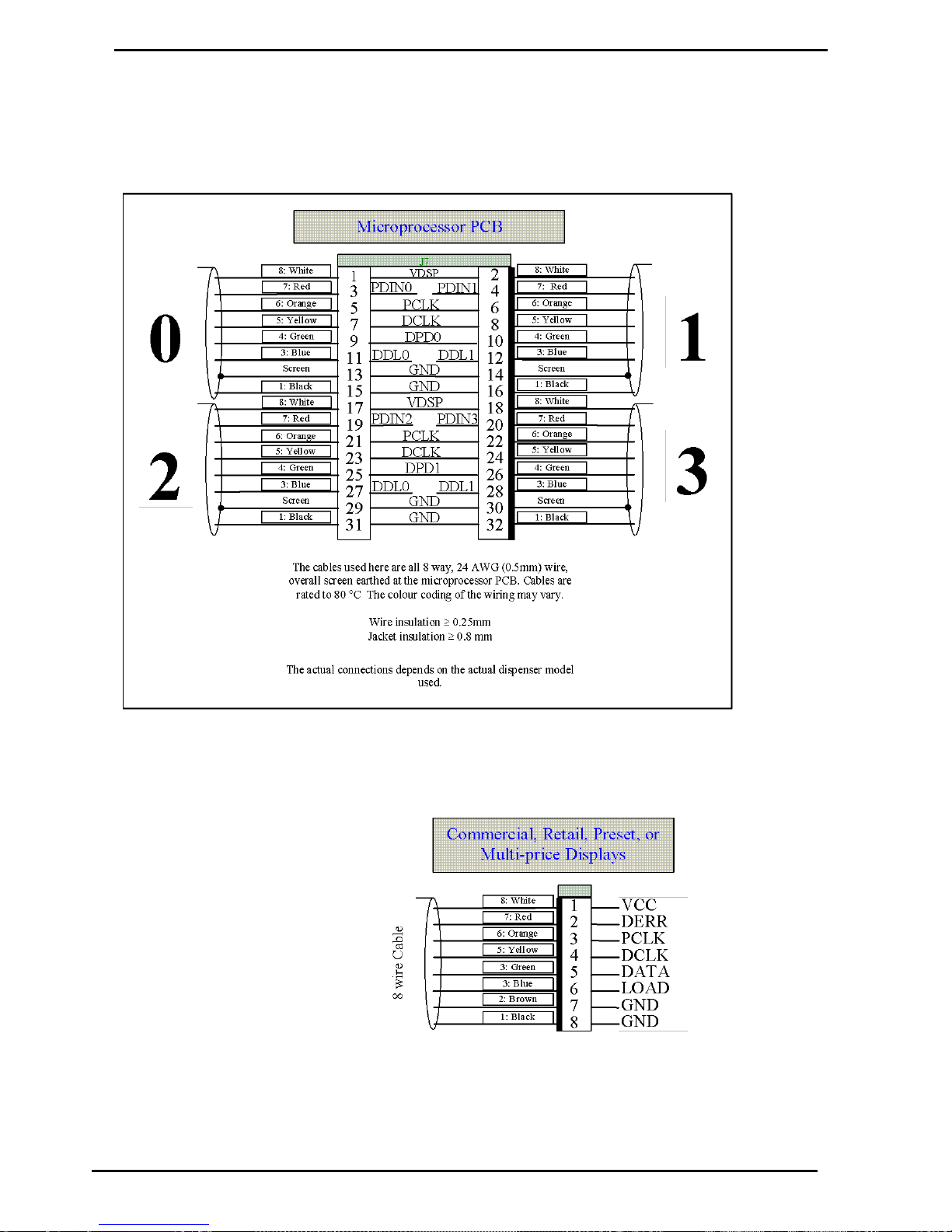
Displays: Litres only, Retail, Multi-price & Preset
Electrical Wiring C4000
Compac Industries Ltd.
Page 52
www.compac.co.nz
Displays: Litres only, Retail, Multi-price & Preset
The C4000 has a 32 pin connector on the microprocessor PCB (refer
General C4000 Figure 1 J7) which can be used to connect up to four
display-preset pairs (see Figure 16 below).
Figure 16. Microprocessor Display Connector (J7)
Figure 16 and Figure 17 show the two ends of the display/preset/multi-price
display cables. The heavy line on one side of the plug indicates the side
with the locking pins.
Figure 17. Display Connector
Figure 18 shows how the displays connect to the C4000 for various
dispenser models. The four circuits (0-3) shown in Figure 18 are the same
four circuits shown in Figure 16.
Page 53
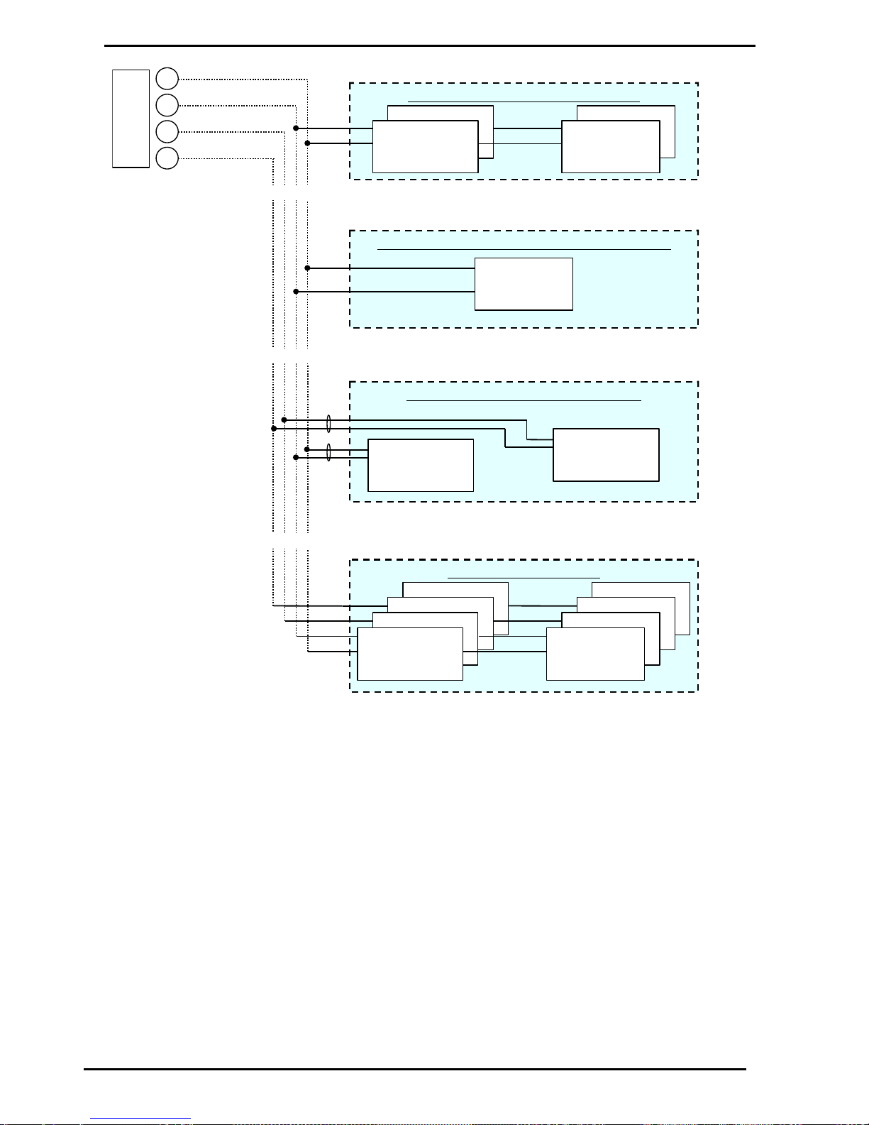
Electrical Wiring C4000
Displays: Litres only, Retail, Multi-price & Preset
Compac Industries Ltd.
Page 53
www.compac.co.nz
OR
Single, Du al, Duo , or Double configuration
Preset D isplay
CI120
& K eypad
CI114
Retail or Com m e rcial
Displays. A P 2 09,
CI121, CI123, CI1 27,
or C13 7
Side A
Side B
All hose Quad co nfig uration
Preset D isplay
CI120
Keyp ad
CI114
Retail or Com m e rcial
Displays. AP209,
CI121, CI123, CI1 27,
or CI137
Side B /2
Side B /1
Side A /2
Side A /1
OR
One side of a six hose true m ulti-product con figuration
M PD Display.
CI147
& K eypad
CI149
From C4000
M icroprocessor.
Four h ose True M ulti-product configuration
M PD Display.
CI147
& K eypad
CI149
M PD Display.
CI147
& K eypad
CI149
Side A
Side B
OR
Figure 18. Display Connections for Various Dispenser Models.
Page 54
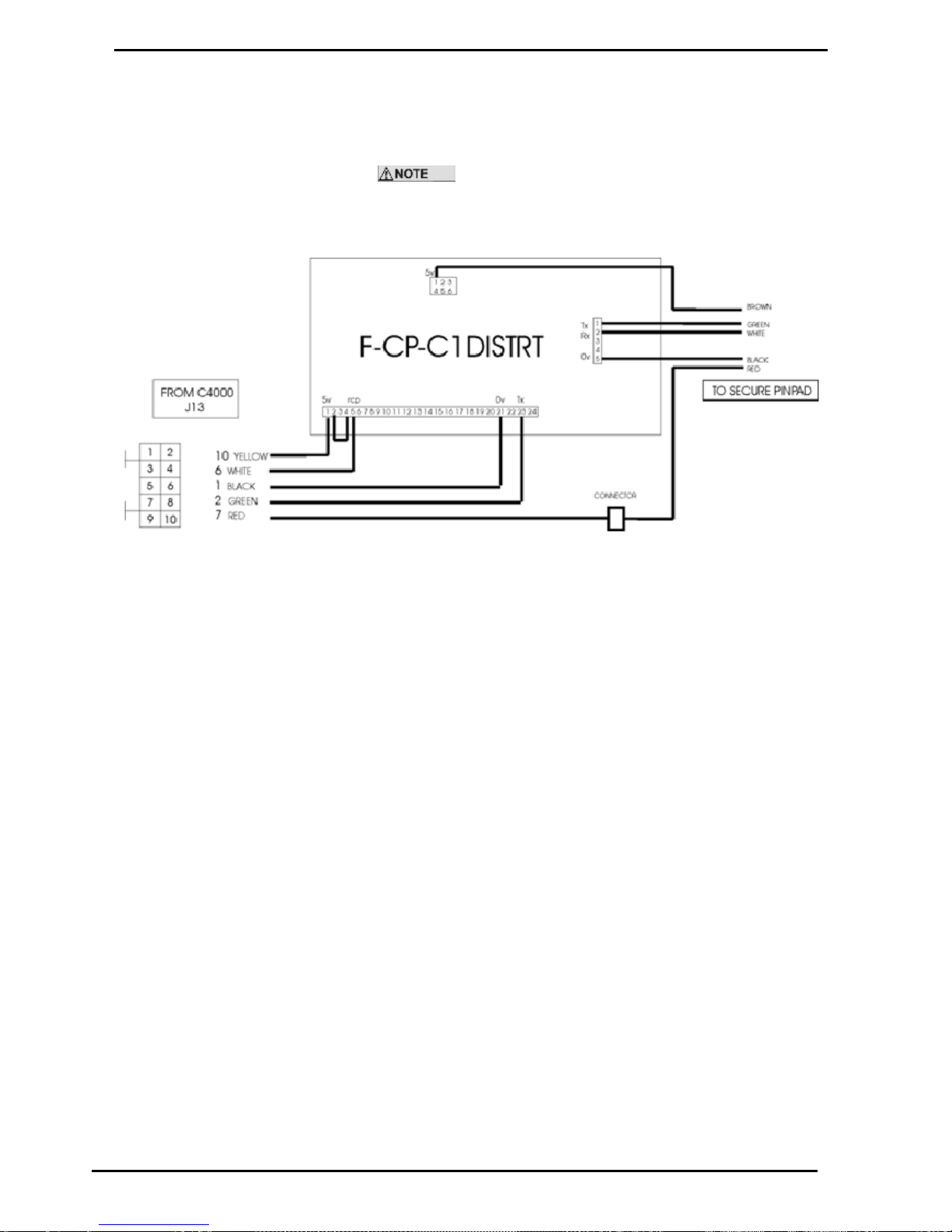
Displays: Litres only, Retail, Multi-price & Preset
Electrical Wiring C4000
Compac Industries Ltd.
Page 54
www.compac.co.nz
Secure PIN Pad Unit
When connecting a BP Secure PIN pad to a C4000 a Distribution board CI36 is required as an interface.
The Secure PIN pad / C4000 combination only works with old
type Central Controllers
Special software is required for the C4000. Secure PIN pads are not
supported in either Futra or Communicator Controller software.
Figure 19. Secure PIN Pad
Modem
This device is not covered in this part of the manual. Refer to the FUTRA
Service Supplement.
Page 55

Electrical Wiring C4000
Displays: Litres only, Retail, Multi-price & Preset
Compac Industries Ltd.
Page 55
www.compac.co.nz
Encoder
The rotary encoder translates meter turns into electrical pulses. Each turn
of the Bennett meter equals approximately 0.5 litre (eight turns = one US
gallon). The encoder converts this to 150 pulses so that each pulse
corresponds to approximately to 3ml.
Exact values are:
One rotation = 0.47 litre
150 pulses = 0.47 litre
One pulse = 3.1 ml
When the C4000 'head' is used for other meters this ratio can vary, e.g.
from 0.5 litres / turn to as high as 10 litres / turn.
The encoder will rotate up to 600 rpm before 'tripping' an „Er 7‟ message. If
the encoder is disconnected, the C4000 will not start the pump and an „Er 9‟
message will be displayed.
The encoder connects to the C4000 via a six-core (only five cores used)
data cable. The five cores used are:
Orange or White - 5V terminal
Yellow or Black - 0V terminal
Brown - B0 terminal
Blue - B1 terminal
Red - B2 terminal
Where B0, B1 & B2 are the three opto-senser connections
To reverse the rotation of the encoder sensing, the B0 & B2 wires should
be reversed. The error message for reverse rotation is „Er 8‟.
Plug
Name
Single
Single Suction,
Dual, & true
Dual
Quad
MHD's &
MHP's
ENC 0
(J3)
Encoder from
meter
Encoder from
side 'A' meter
Encoder
from side 'A',
product 1
Encoder
from product
'1'
ENC 1
(J4)
Not used
Encoder from
side 'B' meter
Encoder
from side 'A',
product 2
Encoder
from product
'2'
ENC 2
(J5)
Not used
Not used
Encoder
from side 'B',
product 1
Encoder
from product
'3'
ENC 3
(J6)
Not used
Not used
Encoder
from side 'B',
product 2
Not used
Page 56

Displays: Litres only, Retail, Multi-price & Preset
Electrical Wiring C4000
Compac Industries Ltd.
Page 56
www.compac.co.nz
High/Low Flow Switch
A High Flow/Low Flow option is available on high flow dispensers/pumps. The
two-position switch is located on the side of the dispenser/pump by the nozzle
holster.
In the high flow position, the full flow rate of the pump/dispenser will be
available at the nozzle. In the low flow position approximately 40 to 70 lpm will
be available depending upon the application.
High/Low Flow Operation Methods
Method 1
When the pump is fitted with a hi-lo flow switch, it enables the user to be
able to select two different flow rates.
The switch has two positions: UP for high flow, and DOWN for low flow
(80litres/m). The two termination screws are located at the top.
When the hi-lo switch is used in the "HI" position, it energises outputs on the
C4000 to operate motors #1 and #2 (with a one-second interval before
motor #2 starts), which in turn operates their associated pump.
When the hi-lo switch is in the "LOW" position, only motor #1, and its
associated pump operates.
The changing of the Flow Selector switch position during a
transaction has an immediate effect on 'Pump 2's' operation. I.e. The motor
for 'Pump 2' can be turned off and on during a transaction.
Method 2
This is used in dispensers supplied by submersible pumps and in pumping
units with a preset operation.
Two solenoids valves 38mm NB & 18mm NB are installed in parallel after
the meter. For high flow, both solenoids valves are open. For low flow, only
the 18mm NB solenoid valve is open.
Method 3 - 3 Phase Pump (M200P)
This is used in pumping units without preset operation.
One 18mmNB-solenoid valve is piped as a 'by-pass' across the pumping
unit. When open this allows some of the product being pumped to return to
the inlet (low-pressure) side of the pump and hence reduces the flow rate
through the nozzle.
Electrical Connections
To control the solenoids in high/low flow operation, the two core cable from
the flow selector switch connects to 'FLOWx' or 'FLOWx' terminals on the
C4000 Microprocessor PCB connector J12 (see Figure 10). 'FLOW0' is
used for side 'A' and in the case of a dual with high/low flow on both sides,
then side B's flow selector switch connects to the 'FLOW1' terminal. The
switches are to be connected between the 'FLOWx' terminal and 'GND'.
Closing the contacts on the flow selector switch of Side 'A' ('FLOW0')
causes the 'T7' output terminal to energise. For Side B the 'T9' output
terminal is energised. In Method 1 the 38mmNB Solenoid is wired to the
'T7' output and the flow-selector switch is 'closed' in the high flow position.
In Method 2 the 18mmNB Solenoid is wired to the 'T7' output and the flowselector switch is 'closed' in the low flow position.
Page 57

Electrical Wiring C4000
Displays: Litres only, Retail, Multi-price & Preset
Compac Industries Ltd.
Page 57
www.compac.co.nz
Totalisers
Electromechanical Totalisers
Only approved Compac totalisers are to be used. Some totalisers have a
+ve and a -ve terminal.
Electronic Totals
As well as having electromechanical totalisers for litres dispensed from the
pump, each C4000 stores in its memory a five-digit litres total of fuel
dispensed from each hose. Both these totals are non-resettable.
These totals can be displayed by pressing the CANCEL or FILL buttons on
the preset keypad, of the meter/hose in question, five times in quick
succession.
The totals will then appear on the pump displays, on the LITRES and
DOLLARS display, for ten seconds before the display resets.
In the absence of a preset keypad, remove the nozzle from the nozzle
holder. Hold the nozzle switch down for at least three seconds and then tap
it down five times in quick succession. The totals will appear as described
above.
Page 58

Displays: Litres only, Retail, Multi-price & Preset
End of Sale Indications
Compac Industries Ltd.
Page 58
www.compac.co.nz
End of Sale Indications
The C4000 can display the reasons the last sale ended. This information is displayed as a number, which appears
in the price-per-litre panel, when setting the pump number. The following table gives the reasons corresponding to
each number.
Numerical
Indicator
Readout
Explanation
1.00
"NOZ"
Nozzle hung up.
2.00
"PRESET"
Stopped at the preset. For CNG dispensers - completed a
temperature compensated fill
3.00
"TIMEOUT"
No flow.
4.00
"REMSTOP"
Pump controller initiated stop.
5.00
"MAX"
Maximum litres and/or dollars reached.
6.00
"AIR"
"GAS"
Air cut-out (Diesel air cut-out switch).
Creepage due to vapour (LPG Dispenser).
7.00
"ERROR"
Encoder error, excess flow, etc.
8.00
"SEQUENCE"
CNG applications only.
9.00
"SUMP"
Switch activated by leaking product.
10.00
“BULK SAFETY”
11.00
“NEW CWID”
12.00
“DPE MAIN”
Parity error on main display
13.00
“DPE MP”
Parity error on multi price display
14.00
“DA MAIN”
Parity error on main display
15.00
“DA MP1”
Parity error on multi price display 1
16.00
“DA MP2”
Parity error on multi price display 2
17.00
“DA MP3”
Parity error on multi price display 3
18.00
“DA MP4”
Parity error on multi price display 4
19.00
“LPG CREEP”
20.00
“TC1”
CNG Temperature compensated fill stage 1
21.00
“TC2”
CNG Temperature compensated fill stage 2
22.00
“TC3”
CNG Temperature compensated fill stage 3
Page 59

Software Upgrade Procedure
Displays: Litres only, Retail, Multi-price & Preset
Compac Industries Ltd.
Page 59
www.compac.co.nz
Software Upgrade Procedure
This is the software upgrade procedure to be followed for all bulk meter
registers and all pumps with a C4000 other than those with FUTRA
software.
1. Ensure, before working on the pump, that anti-static precautions are
taken (i.e. wearing of wristband with earth strap).
2. Gain access to C4000 Processor Board and record all set-up data by
accessing the configuration (K-Factor) switch and the parameter
switch, this includes recording the comms dipswitch settings. Data setup to include:
3. K factor 'F '
4. No flow delay 'n'
5. Pre-set cut-off margin 'PCut'
6. Density Factor 'dSF' (CNG only)
Specific density 'SPG' (LPG only) Flow rate 'FLO' 'r' (some
bulkmeters only)
Temperature 'E' (bulk meter or LPG only)
L Cut 'L' or 'LCUT' (bulkmeter only)
H Cut 'H' or 'HCUT' (bulkmeter only)
F Cut 'F' or 'FCUT' (bulkmeteronly)
Set resolution 'Sr'
Configuration 'C '
'b' Settings
Price 'Pr' or 'P'
Density 'd' (bulkmeters only)
Pump number 'Pn'
Sequencing Rate 'SE9' (CNG only)
Access code 'A' (comcard or CWIDKey Basic dispensers only)
7. Electronic and mechanical totals should also be recorded.
8. In the case of 'Comcard Basic', 'Compin' (Mining), or 'CWIDKey Basic'
systems, a printout of card/pin/key totals must be obtained before
changing software. This printout will also give card/pin/key validation
status. If no printer is available, use Scrolling Tote option (refer
Totalisers (see page 57)).
9. The above steps are taken to safeguard against software
incompatibility causing loss of information.
10. Turn off power.
11. Remove software EPROM (removable chip labelled C4000 PXX or XX-
X-XX:XX.X) using an EPROM extractor. (See Figure 1 for the location
of the EPROM.)
12. Plug in new software EPROM, being careful that the dimple is at the
correct end of the socket. (i.e. software chip dimple to base dimple).
Also that all the legs are correctly located in the socket (see diagram
below).
13. Turn on power.
14. Check that the data recorded in Steps 2 and 4 is still present, if not re-
enter.
15. Check the electronic totals, if not as before then give 'before' and 'after'
totals to relevant people on site.
16. Ensure that the status of cards/pins/keys, on 'Comcard', 'Compin', or
CWIDKey systems, are as before. If they are different in any way,
ensure that the relevant people on site receive 'before' and 'after'
Page 60

Displays: Litres only, Retail, Multi-price & Preset
Software Upgrade Procedure
Compac Industries Ltd.
Page 60
www.compac.co.nz
printouts of card/pin/key totals.
17. Test pump operation.
When replacing Integrated Circuit chips (refer to Figure 19
below), ensure that the notch is facing in the direction of the IC board
socket (the notch is the end that we refer to as the "front").
When inserting the IC chip, the rear pin (of the IC chip) must be plugged
into the rear pin socket of the IC board socket. Any spare pin sockets
should be in front.
Failure to correctly insert the IC chips or adhere to the above guidelines
specified herein will result in a loss of memory data.
Figure 3: Memory chip installation
Figure 20. Software IC Insertion
Page 61
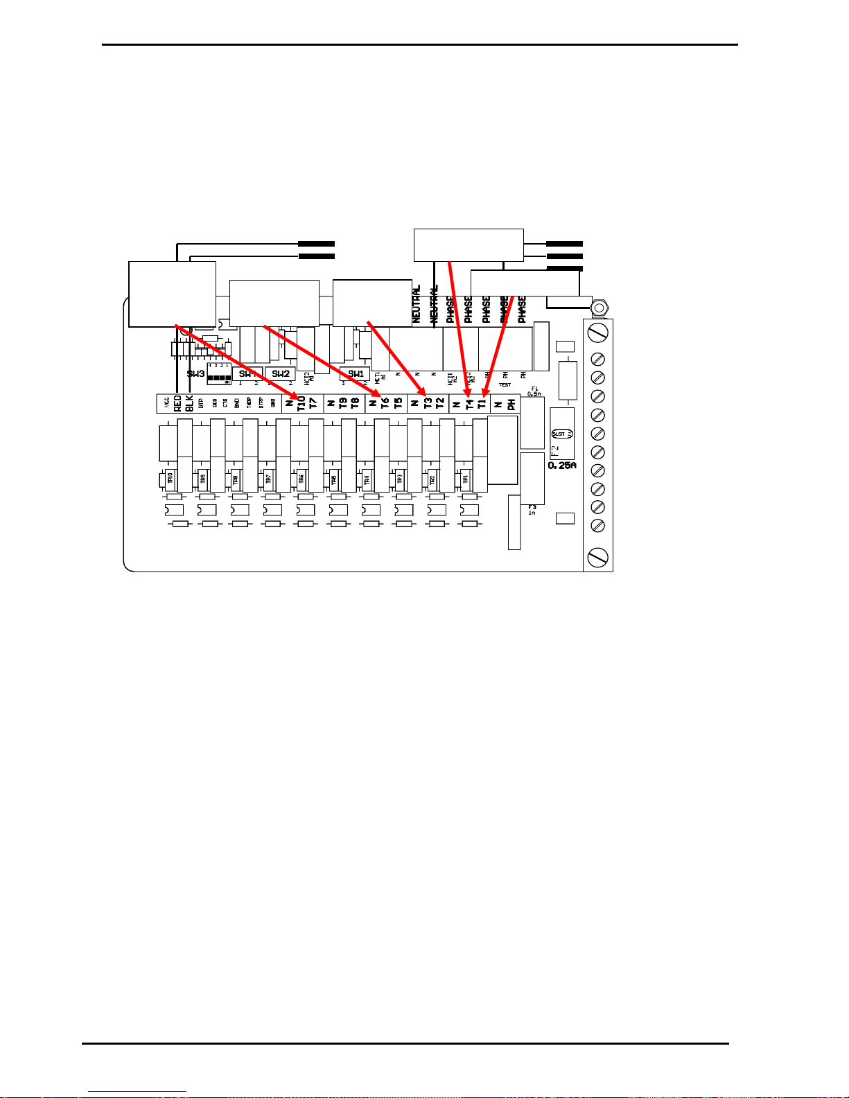
Solid State Relays (Triacs)
Displays: Litres only, Retail, Multi-price & Preset
Compac Industries Ltd.
Page 61
www.compac.co.nz
Solid State Relays (Triacs)
General
The solid state relay, as the name implies, is a solid state switch, controlled
by the C4000. These solid-state switches control the C4000 220-240volt
outputs.
Neutral
Phase
Earth
+ ve
- ve
COMMS
INCOMING MAINS
Motor Side B
Solenoid
Side A
Solenoid
Side B
Excess
Flow
Output
Motor Side A
Figure 7. Location of Solid State Relays (Triacs) and Comms DIP Switches (SW3)
There are 10 separate solid state relays (small triacs) on the C4000 PCB.
The output terminals for these triacs is T1 to T10. Their function varies
depending on what the C4000 'head' is controlling. Below are tables
showing the use of these outputs for various applications.
The T1 and the T4 outputs can be used to drive a high current triac whose
output will be on the LOAD1 and LOAD2 terminals respectively. Each of
these outputs (T1 and T4) has an associated switch (SW1 and SW2
respectively) which must be used to select the type of output required (refer
Figure 8).
The T7 output cannot drive a high current triac directly but may be looped to
T1 or T4 of another C4000. If it is looped then SW4 must be in the mid
position. Position 1 of SW4 should never need to be used.
The power for the triac outputs can be supplied from a separate mains
supply (Separate from the supply for the microprocessor). There are two
blocks of connectors for the phase connection (refer Figure 7). The block of
six connectors supplies the microprocessor and the block of four connectors
supplies the triac outputs. These two blocks of connectors are normally
looped together in the factory.
Page 62
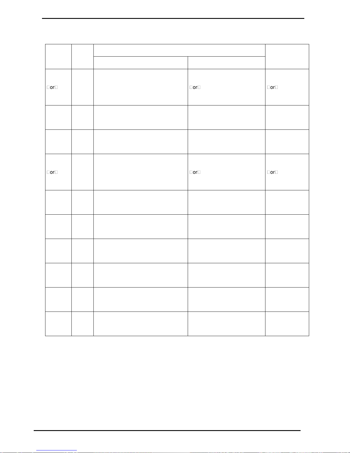
Triacs C4000 Single, Dual & Quad
Solid State Relays (Triacs)
Compac Industries Ltd.
Page 62
www.compac.co.nz
Triacs C4000 Single, Dual & Quad
Power
Symbol
Function
High / Low
Terminal
Single / Dual
Quad
Current Output
T1
LOAD1
MTR1
Motor relay control (SW1 = 2)
or
Internal pump motor (SW1 = 1)
Motor relay control (SW1 = 2)
Internal pump motor (SW1 = 1)
Low 300mA max
High (40 A max)
T2
SFS1
Secondary Flow Coil
Solenoid 1
Secondary Flow Coil
Solenoid 1
Low (300 mA max)
T3
PFS1
Primary Flow Coil
Solenoid 1
Primary Flow Coil
Solenoid 1
Low (300 mA max)
T4
LOAD2
MTR2
Motor relay control (SW2 = 2)
or
Internal pump motor (SW2 = 1)
Motor relay control (SW2 = 2)
Internal pump motor (SW2 = 1)
Low 300mA max
High (40 A max)
T5
SFS2
Secondary Flow Coil
Solenoid 2
Secondary Flow Coil
Solenoid 2
Low (300 mA max)
T6
PFS2
Primary Flow Coil
Solenoid 2
Primary Flow Coil
Solenoid 2
Low (300 mA max)
T7
SFS4
Spare
Secondary Flow Coil
Solenoid 4 (SW4 = 2)
Low (300 mA max)
T8
SFS3
Spare
Secondary Flow Coil
Solenoid 3
Low (300 mA max)
T9
PFS3
Spare
Primary Flow Coil
Solenoid 3
Low (300 mA max)
T10 PSF4
Spare
Primary Flow Coil
Solenoid 4
Low (300 mA max)
Page 63
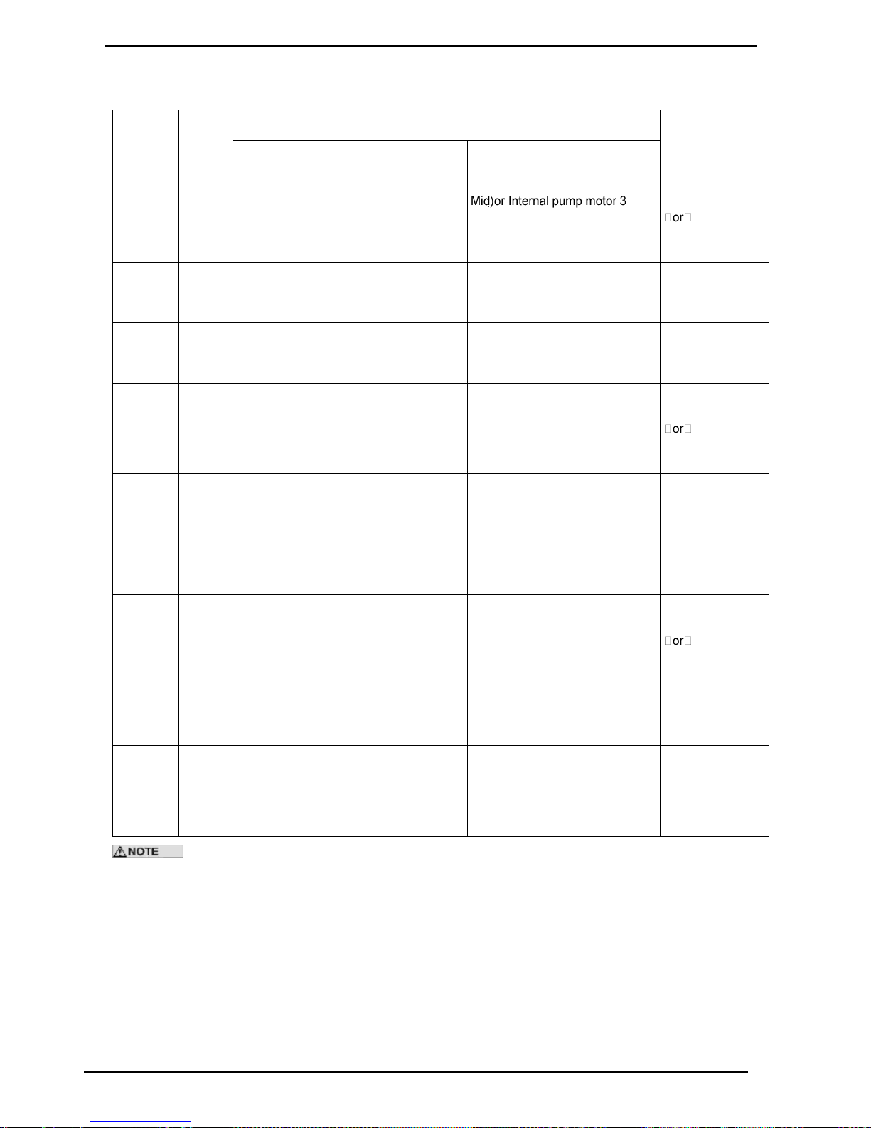
Solid State Relays (Triacs)
Triacs C4000 MPD6 & MPP6 side A
Compac Industries Ltd.
Page 63
www.compac.co.nz
Triacs C4000 MPD6 & MPP6 side A
Power
Terminal
Symbol
Function
High / Low
Current Output
MPD6 / MPP6 side 'A'
MPD6 / MPP6 side 'B'
T1
or
LOAD1
MTR1 /
MTR3
Motor 1 relay control (SW1 = 2)
or
Internal pump motor 1 (SW1 = 1)
Motor 3 relay control (SW1 =
(SW1 = 1)
Low 300mA max
High (40 A max)
T2
SFS1
Secondary Flow Coil
Solenoid 1
Secondary Flow Coil
Solenoid 1
Low (300 mA max)
T3
PFS1
Primary Flow Coil
Solenoid 1
Primary Flow Coil
Solenoid 1
Low (300 mA max)
T4
or
LOAD2
MTR2
Motor 2 relay control (SW2 = 2)
or
Internal pump motor 2 (SW2 = 1)
Motor 2 relay control (SW2 = Mid)
or Internal pump motor 2 (SW2 =
Mid)
Low 300mA max
High (40 A max)
T5
SFS2
Secondary Flow Coil
Solenoid 2
Secondary Flow Coil
Solenoid 2
Low (300 mA max)
T6
PFS2
Primary Flow Coil
Solenoid 2
Primary Flow Coil
Solenoid 2
Low (300 mA max)
T7
MTR3 /
MTR1
Motor 3 relay control (SW4 = 2)
or
Internal pump motor 3 (SW = Mid)
Motor 1 relay control (SW4 = Mid)
or Internal pump motor 1 (SW4 =
Mid)
Low 300mA max
High (40 A max)
T8
SFS3
Secondary Flow Coil
Solenoid 3
Secondary Flow Coil
Solenoid 3
Low (300 mA max)
T9
PFS3
Primary Flow Coil
Solenoid 3
Primary Flow Coil
Solenoid 3
Low (300 mA max)
T10 Spare
Spare
Low (300 mA max)
For a six hose MPD / MPP: T1 of side 'A' loops to T7 of side 'B', T4 of side 'A' loops to T4 of side 'B', and
T7 of side 'A' loops to T1 of side 'B'.
Page 64

Triacs C4000 LPG Single/Dual, CNG & Bulk Meter
Solid State Relays (Triacs)
Compac Industries Ltd.
Page 64
www.compac.co.nz
Triacs C4000 LPG Single/Dual, CNG & Bulk Meter
Power
Terminal
Function
High / Low
LPG Single/Dual
CNG
Bulk Meter
Current output
T1
Electric Motor Control (SW1 =
2) side „A‟
Low A (SW1 = 2)
Electric Motor Control (SW1 = 2)
Low (300 mA max)
T2
Secondary Coil Solenoid
Control Side „A‟
Spare
Low Flow. New Compac OCV
Control N/C Solenoid
Low (300 mA max)
T3
Primary Coil Solenoid Control
Side „A‟
Med 1A
High Flow. New Compac OCV
Control N/C Solenoid
Low (300 mA max)
T4
Electric Motor Control (SW2 =
mid) Side „B‟, looped to T1
High A (SW2 = 2)
Tank Valve Signal (SW2 = 2)
Low (300 mA max)
T5
Secondary Coil Solenoid
Control Side „B‟
Spare
Spare
Low (300 mA max)
T6
Primary Coil Solenoid Control
Side „B‟
Low B
Caltex
Low (300 mA max)
T7
Spare
Med 1B (SW4 = 2)
Mobil (SW4 = 2)
Low (300 mA max)
T8
Spare
Spare
Shell
Low (300 mA max)
T9
Spare
High B
BP
Low (300 mA max)
T10
Excess flow output - Turned on
if flow rate exceeds
100litres/min. Stays on until
dispenser turned off.
Auxiliary Output for
CNG Compressor
Control
Additive Pulse
Low (300 mA max)
Page 65
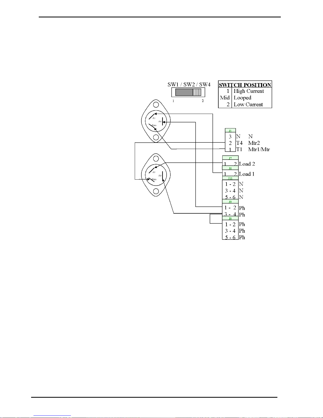
Solid State Relays (Triacs)
High Current Triac Option
Compac Industries Ltd.
Page 65
www.compac.co.nz
High Current Triac Option
Where high current (40A) outputs are required (i.e. driving the pump motor
directly) high current triacs are fitted to the power supply PCB. If a high
current triac is installed for T1 and/or T4 then its respective snubber switch
(SW1 & SW2 respectively) needs to be switched to position 1 (Refer Figure
8).
Figure 8 High Current Triac Option
Page 66
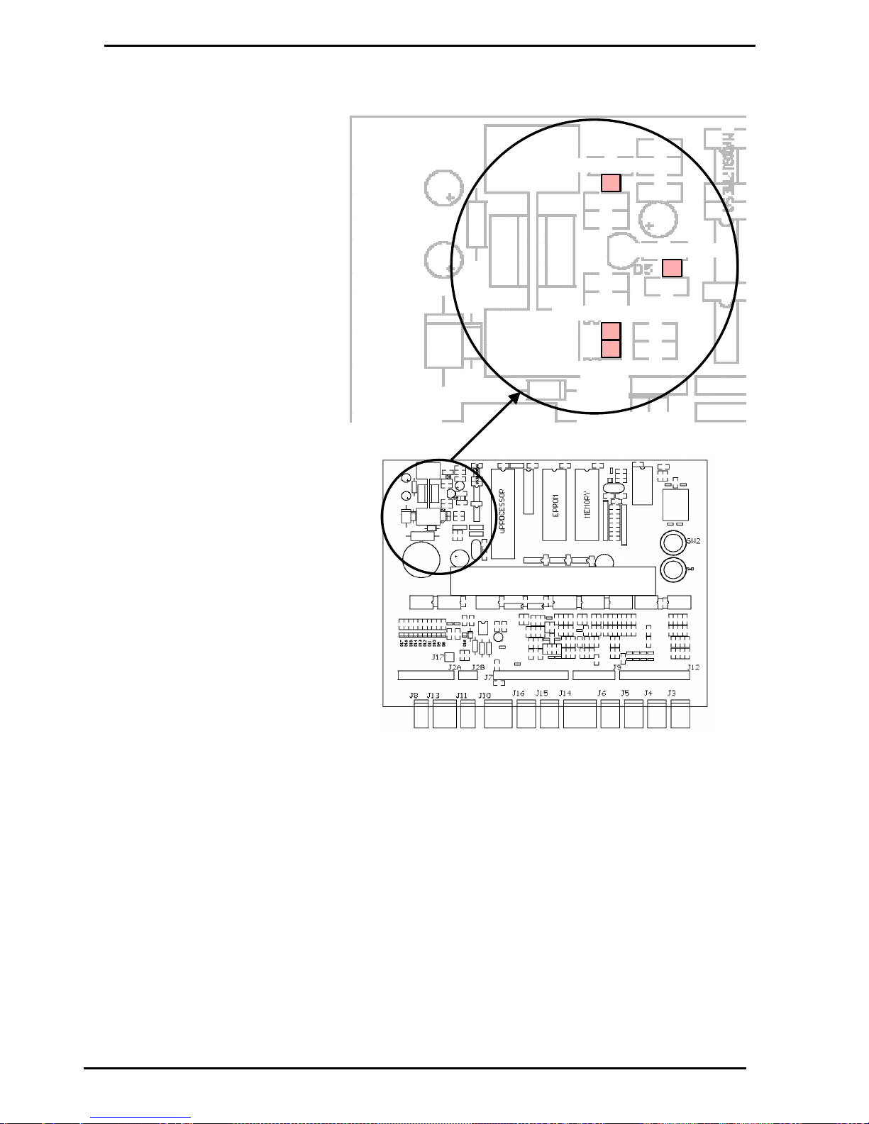
High Current Triac Option
Indicator LEDs
Compac Industries Ltd.
Page 66
www.compac.co.nz
Indicator LEDs
C4000 microProcessor PCB
D1
D5
D6
D7
POW ER LED
W AT CHD OG LED
CO MM S RX D LE D
CO MM S TXD LE D
Figure 5. Location of Power, Watchdog, RXD & TXD LEDs
Power LED
The Power LED (refer Figure 5) lights when the processor board has
power. If this LED flashes, this indicates that the processor has a fault on
the processor power supply.
WatchDog LED
The Watchdog LED (refer Figure 5) lights only if the watchdog circuit has
been triggered, thereby indicating that a processor fault has occurred.
TXD & RXD LEDs
The TXD and RXD LEDs (refer Figure 5) indicate polling of communications
to/from a controller. The RXD LED flashes whenever any communications
polling is received and the TXD LED flashes whenever the C4000
processor responds to polls for its respective pump number(s).
Page 67
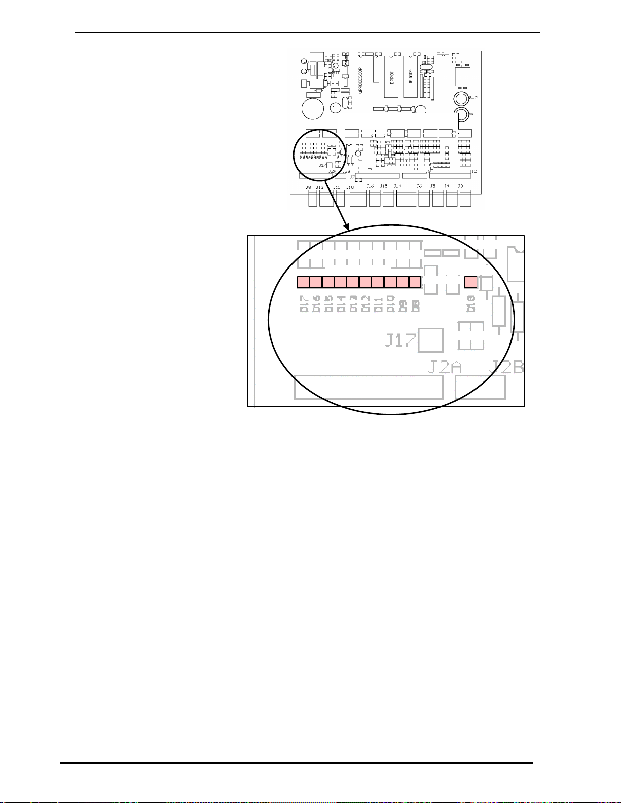
Indicator LEDs
High Current Triac Option
Compac Industries Ltd.
Page 67
www.compac.co.nz
D17
D16
D15
D14
D13
D12
D11
D10D9D8
D18
Output LE D s
Dia gn ostic L E D
C4000 m icro Processor P CB
Figure 6. Location of Output & Diagnostic LEDs
Output LEDs
The ten Output LEDs (refer Figure 6) indicate which triac outputs are being
switched on. D8-D17 corresponds to the output triacs T1-T10 (refer Figure
7).
Diagnostic LED
The Diagnostic LED Figure 6) flashes in three different states when the
processor is working properly:
When the pump is idle and in 'stand-alone' mode, the LED flashes
slowly and consistently.
When the pump is idle and communicating with a controller the LED
flashes slowly but erratically.
When the nozzle is lifted from its holster, the LED flashes quickly.
Page 68

High Current Triac Option
Fault Finding
Compac Industries Ltd.
Page 68
www.compac.co.nz
Fault Finding
Symptom
Action
Watchdog LED is on
(refer to Figure 5 for the location of the
Watchdog LED)
Is the processor LED (DL1) flashing?
Yes - Turn power off
Check for any foreign bodies i.e. wire off-cuts etc, on processor PCB.
Check all IC's are firmly in their sockets.
Re-power the C4000
If watchdog resets (i.e. stays off), then everything is okay.
Replace C4000 PCB if watchdog still comes on after re-power.
No - Replace C4000 PCB.
Are IC's plugged in correctly?
Are IC chips the same?
Is LK1 made?
Are intrinsic plugs plugged in correctly?
Diagnostic LED not flashing
(refer to Figure 6 for the location of the
Diagnostic LED)
Is Power LED on?
Yes - Replace C4000 PCB
No - Refer below
Power LED off
(refer to Figure 5 for the location of the
Power LED)
Is the power to the C4000 on?
Yes - Check Fuse F1
Check for a short on intrinsic devices. Unplug and re-plug each device,
checking the power LED status each time.
If the LED still off, turn power supply off for a few minutes then back on & try
again.
Replace C4000 PCB if fault not found
No - Turn on power supply & try again.
Motor won't start
Is Solid State Relay LED on?
Yes - Check Triac Fuse F2
Check all Motor connections
Check Motor
Check wiring
Select a spare High Current Solid State Relay if the above checks are ok.
No - Check Nozzle Switch wiring & operation.
Page 69

Fault Finding
High Current Triac Option
Compac Industries Ltd.
Page 69
www.compac.co.nz
Replace C4000 PCB if fault not found
Motor running all the time
Is Solid State Relay LED on?
Yes - Check Nozzle Switch is releasing
No - Select a spare High Current Solid State Relay.
Replace C4000 PCB if fault not found
Solenoid not energising
Is Solid State Relay LED on?
Yes - Check Triac Fuse F2
Check all Solenoid connections
Check Solenoid
Select a spare Low Current Solid State Relay if the above checks are okay.
No - Check Nozzle Switch operation.
Replace C4000 PCB if fault not found
Preset Display Digit flashing
Is the respective Preset Button stuck in?
Yes - Remove grit if any and check spacing of keypad to fascia gives good key
operation.
Check wiring & condition of display plugs.
No - Replace keypad. If problem still exists, replace preset PCB.
Secure PIN Pad - Display Off
Is PIN pad backlighting on?
Yes - Check 5V and TX wires for continuity.
NO - Check the 0V wire for continuity and that the plug is secure.
Replace Secure PIN pad if fault is not found.
Secure PIN Pad not accepting
numbers
Is PIN pad display on?
Yes - Check RX wire for continuity
No - Check cable and plug.
If no fault found, replace the Secure PIN pad.
Star Printer not working
Is power on?
Yes - Check connection of comms cable
Check dip switch settings (refer Printer Set-up (see page 40))
Carry out self test (refer Printer Set-up (see page 40))
No - Check cable and plug.
If no fault found, contact Compac Help Desk.
Page 70

Error Codes
Fault Finding
Compac Industries Ltd.
Page 70
www.compac.co.nz
Error Codes
Error Code
Fault
Action
Err 3
No price set.
Set a price at the pump or at the controller.
Err 4
CWID offline.
Check connections.
Change CWID PCB.
Err 7
Excess flow.
Check for air.
Err 8
Excess reverse rotation of encoder.
Check product is not flowing back into the tank
once the delivery has finished.
Err 9
Faulty encoder or disconnected encoder.
Check encoder circuit.
Err 10
Configuration Lost
Reconfigure C4000
Err 11
Invalid access code
(Comcard or CWIDKey Basic systems only).
Enter valid access code.
Err 12
C4000 memory failure.
Change memory E2prom 'chip'.
Err 13
Temperature/Pressure Interface unplugged.
Reconnect interface board or replace.
Err 14
Temperature Probe disconnected.
Reconnect temperature probe or replace.
Err 15
Pressure Probe disconnected (LPG only).
Reconnect pressure probe or replace.
For Error 7 (LPG) also occurs if flow rate exceeds 100 litres/min.
For Error 8 excess reverse rotation means the encoder has turned
backwards more than 3/4 of one turn during a delivery, or within two
seconds of the end of a delivery. This only occurs if the non-return valves
installed on site are faulty.
Page 71

Fault Finding
Error Messages
Compac Industries Ltd.
Page 71
www.compac.co.nz
Error Messages
On Pump
LCD
Display
On PIN Pad Dot
Matrix Display (if
Connected)
Explanation
REPAS
Pass Again
Card not read properly, try re-swiping. In addition, C4000 may be configured for
the wrong card reader track, or the card or card reader could be faulty.
HOLD
System not ready
Pump no longer communicating with Central Controller.
:0.0
The full-colon on the display indicates that the processor supply has been OFF
and back ON since the last transaction.
_ _ _ _ _
Restricted Fuel
Card not validated for the pump/dispenser fuel grade set.
_ _ _ _ _
Wrong System
Incorrect card used or the controller has the incorrect access code or ISO number
set. Or requires setting for a particular Card Type.
_ _ _ _ _
Expired Card
Card expiry date is earlier than controller date
_ _ _ _ _
Bad Card
Algorithm check sum on cards is invalid
_ _ _ _ _
Wrong Pin
An incorrect or invalid pin has been entered.
_ _ _ _ _
Wrong Network
The network encoded on the card is invalidated in the controller.
RAnGE
Temperature probe out of range. (Only displayed when temperature setting
selected on K Factor Switch). Probe either faulty or not connected.
Low Battery
Fault on Secure PIN pad Processor PCB- replace complete PIN pad.
Memory Error
Fault on Secure PIN pad processor PCB replace complete PIN pad.
AIr
(Flashing)
The air cut-out switch has operated.
GAS
(flashing)
LPG ONLY. Flow rate fell to between 0 and 6 litres/min for more than 6 seconds.
Indicates creepage due to presence of vapour.
Page 72
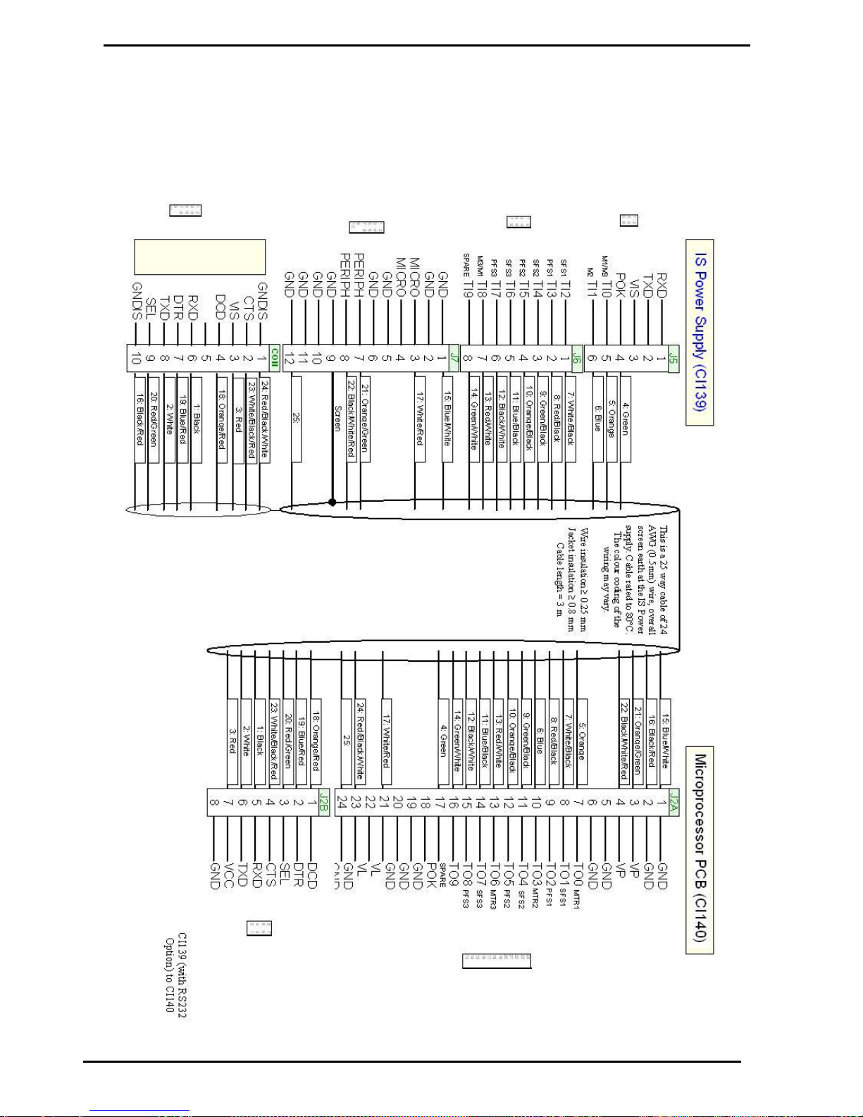
C4000 with RS232 Wiring
Appendix A
Compac Industries Ltd.
Page 72
www.compac.co.nz
Appendix A
C4000 with RS232 Wiring
Page 73
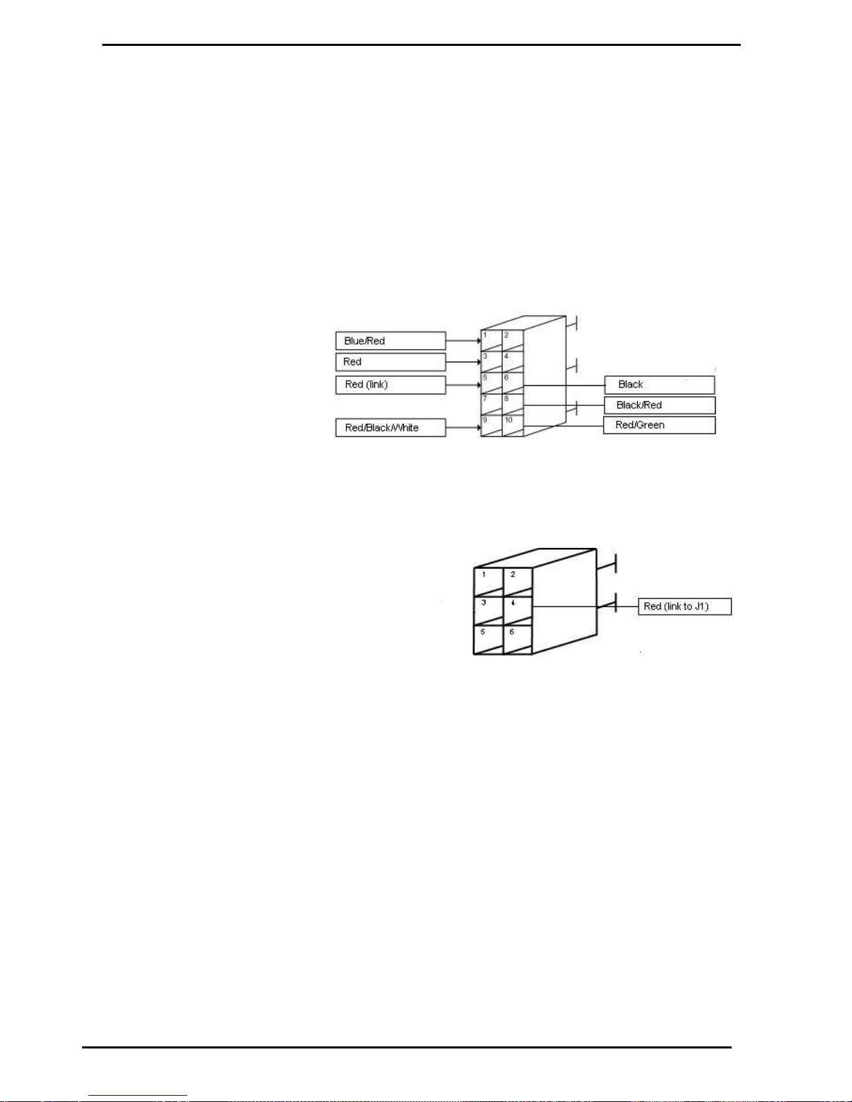
Appendix A
RS485 Wiring
Compac Industries Ltd.
Page 73
www.compac.co.nz
RS485 Wiring
The following changes are made to standard Compac dispensers to allow
the use of RS485 communication with other devices.
C4000 Power Supply
1) An RS485 Board is fitted inside the Power supply flame proof box.
2) The IS cable pinouts will need to be changed as detailed below. An extra
red wire will need to be added to link pin 5 on J1 with pin 4 on J5
Figure 4: J1 RS485
Figure 5: J5 Power Supply
C4000 Processor
1) Special software to support the Micromotion CNG50 meter will need to be
installed. Please contact the Compac Helpdesk for the latest version.
2) The IS cable will need to have The Red / Black / White cable removed
from J2A and put into pin 6 of J2B.
Page 74
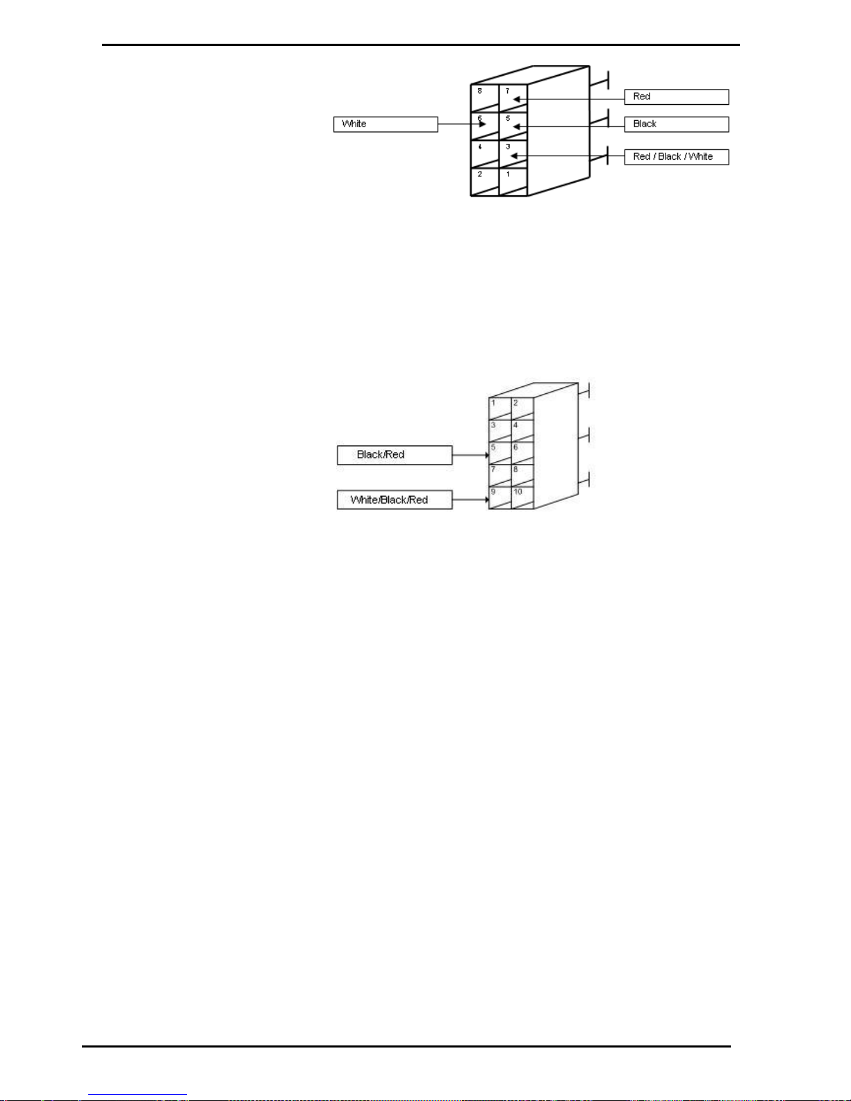
RS485 Wiring
Appendix A
Compac Industries Ltd.
Page 74
www.compac.co.nz
Figure 6: J2B C4000 Processor
3) A new plug will need to be made for J13 and the following wires removed
from J2A and inserted into pins 5 and 9.
Page 75
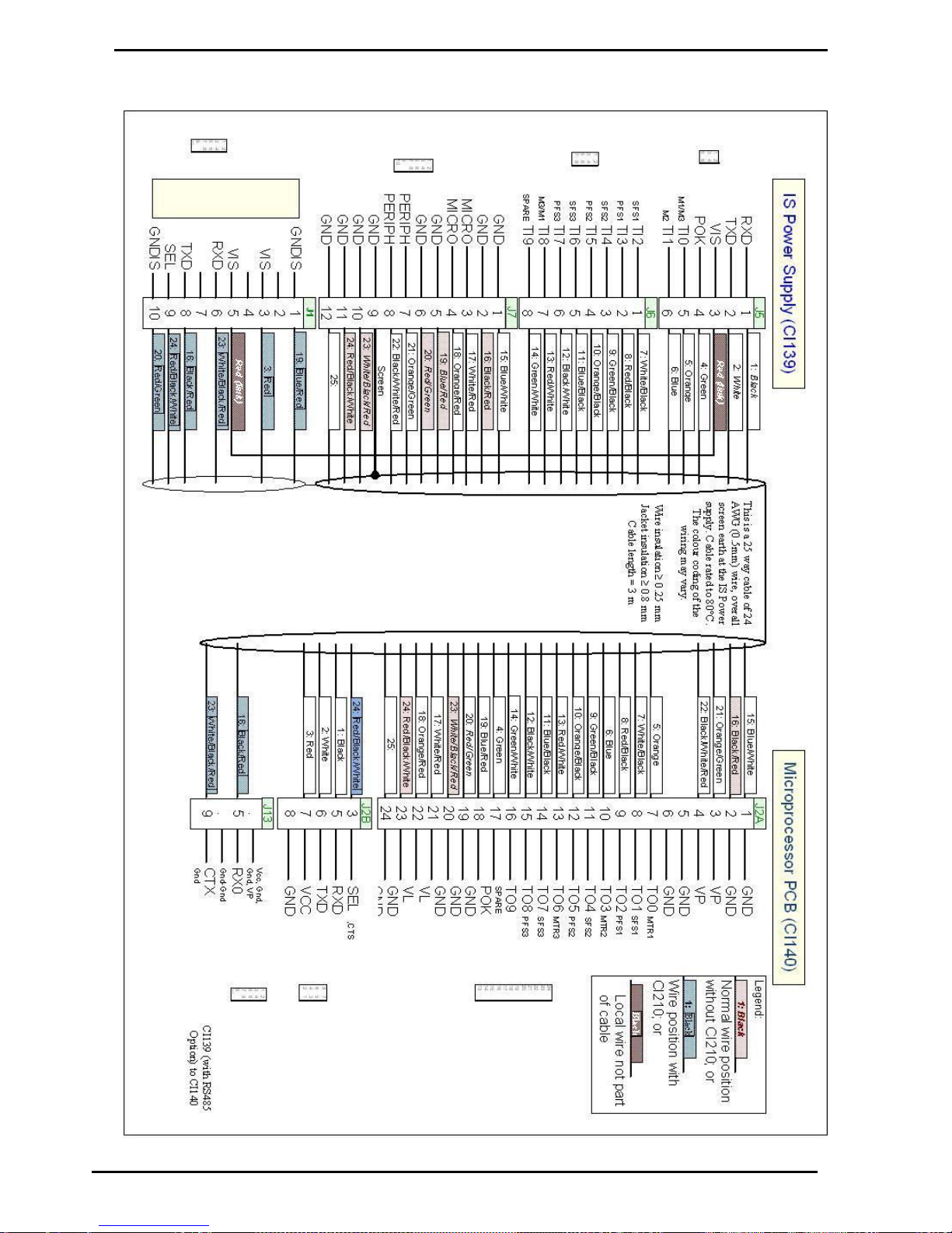
Appendix A
C4000 with RS485 Wiring
Compac Industries Ltd.
Page 75
www.compac.co.nz
C4000 with RS485 Wiring
Page 76
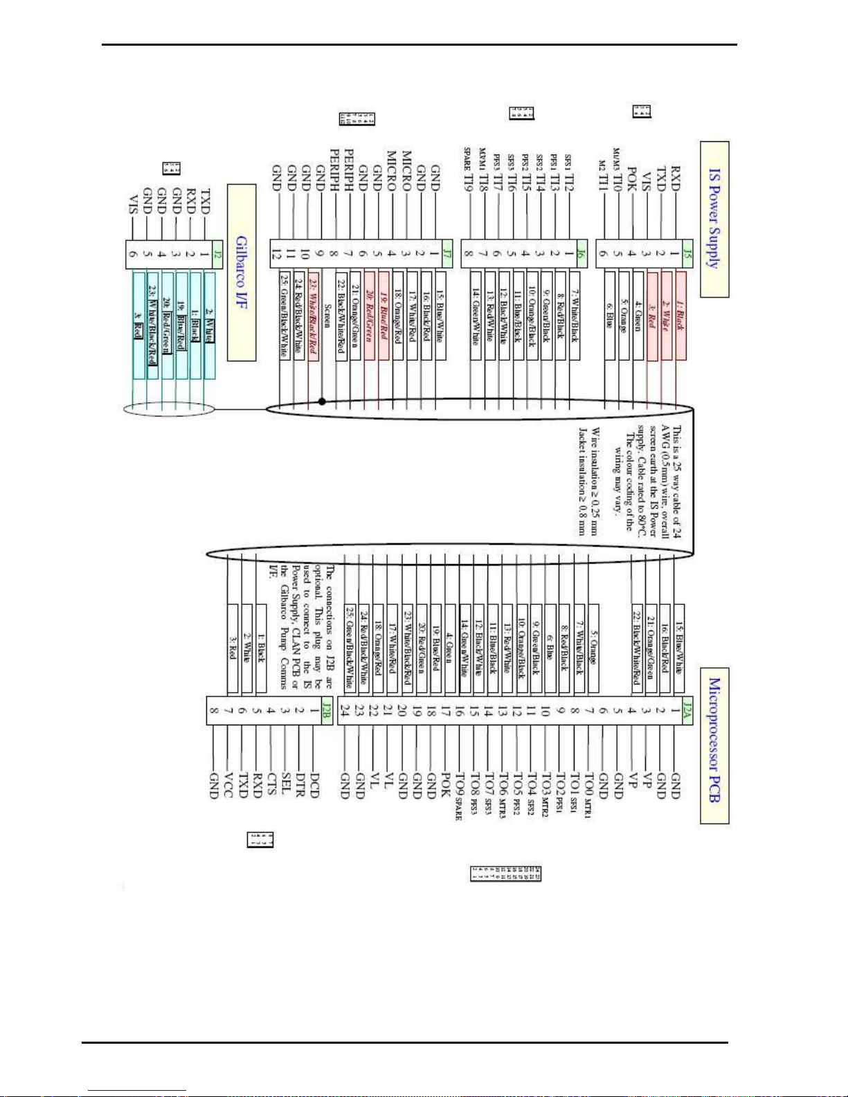
Gilbarco Interface Wiring
Appendix A
Compac Industries Ltd.
Page 76
www.compac.co.nz
Gilbarco Interface Wiring
Page 77

Glossary of Terms
Gilbarco Interface Wiring
Compac Industries Ltd.
Page 77
www.compac.co.nz
Glossary of Terms
TERM
DESCRIPTION
ATG
Automatic Tank Gauging
Class 1 Zone 0
An area in which an explosive-gas atmosphere is present continuously or is present for
long periods.
Class 1 Zone 1
An area in which an explosive-gas atmosphere is likely to occur in normal operation.
Class 1 Zone 2
An area in which an explosive-gas atmosphere is not likely to occur in normal operation,
and if it does occur it will exist for short periods only.
ComFutra
A model of pump mounted authorisation terminal made by Compac.
CPU
Central Processing Unit.
CWID
Compac Wireless Identifier.
DCA
Driveway Card Acceptor - A type of pump authorisation terminal made by Compac.
Encoder
A device that translates rotary motion into electronic pulses. Often referred to as a pulser.
Head
Dispenser calculator/Indicator. C4000 PCB, complete with power supply.
HID
Transponder key authorisation system
Intrinsically safe circuit
A circuit in which any spark or any thermal effect produced in the test conditions
prescribed in the relevant standard (which includes normal operation and specified fault
conditions) is incapable of causing ignition of a given explosive atmosphere.
Intrinsically safe
electrical equipment
Electrical equipment in which all the circuits are intrinsically safe. The equipment may be
self-contained or may form part of an intrinsically safe electrical system.
Intrinsically safe
electrical system
An assembly of interconnected items of electrical equipment in which the circuits or parts
of circuits, intended to be used in an explosive atmosphere, are intrinsically safe circuits.
LED
Light emitting diode.
Memory chip
EPROM chip that stores parameters and/or transaction & totals.
OPT
Outdoor Payment Terminal - A type of authorisation terminal designed for credit card
applications made by Compac.
PCB
Printed Circuit Board.
RAS
Retail Authorisation Station - Authorisation terminal designed for manned sites
Via
'Plated through hole' in a PCB that enables tracks to swap sides on a PCB.
Software chip
EPROM chip with label indicating program version.
 Loading...