

Page 1
COMODORIGS.COM
USER GUIDE
BWL0725/2 Orbit User Guide • 01/2014
Page 2

CONTENTS WARRANTY & LEGAL NOTICE
2 3
contents warranty & legal notice
03 Warranty & Legal Notice
04-05 The Orbit
06 Getting Started: Front View
07 Getting Started: Top View & Camera Plate
08 Set-Up: Vertical Adjustment & Mounting Camera
09 Set-Up: Balancing Camera
10 Set-Up: Fine-Tune Adjustment
11 Using Extension Arms
All Comodo products are covered by a two-year warranty
against any faulty design, materials and workmanship.
If a product does not work on arrival, or up to a maximum
period of four weeks from the date of dispatch of the
product, it should be returned to the dealer/retail outlet
from where it was purchased for exchange (subject to
stock availability). If the faulty unit was part of a kit, the
dealer/retailer may choose to only replace the unit and
not the entire kit.
Alternatively the dealer may offer to repair the unit as soon
as possible at no charge.
If neither an exchange nor repair is possible for the faulty
unit, then a full refund may be made.
If a warranty fault occurs after the initial four week period
(and within the maximum two year warranty period), then
the unit should be returned to the dealer, who will arrange
to repair the unit as soon as possible, at no charge.
This warranty does not apply to consumable items such
as fuses or consumable type batteries.
Should a unit be returned at any time within the two year
warranty period, and it is judged to have experienced any
of the following;
Failure to follow working instructions correctly, accidental
or wilful damage, misuse, alteration or repair by a nonauthorised Comodo service/repair centre, then the
warranty will be deemed invalid and any repairs required
will be payable by the owner.
The dealer, in advance of undertaking any work that may
be required, should notify the cost of any repairs to the
owner.
No warranty repairs can be undertaken to any units
without proof of purchase.
All warranty repairs or returns must be conducted with
the dealer from where the product was purchased.
Other terms and conditions may be applicable in specic
countries, if stated at the time of purchase.
Requesting Service - Comodo products purchased
throughout the world will have varying service and repair
processes depending upon the region it is purchased in.
Please visit: http://www.ComodoRigs.com/Warranty to
determine how to correctly process your service and
repair request.
Comodo™ is a trading style of Bowens International Ltd.
Due to our policy of continual product improvement, Bowens International Ltd reserves the right to change equipment
specications at any time and without notice.
The information contained in this user guide should not be relied on solely before making a purchase, seek further
information from your retailer. © 2013 Bowens International Ltd.
INCLUDED IN BOX
1 x Orbit Camera Rig
2 x Small Extension Arms
2 x Medium Extension Arms
2 x Large Extension Arms
1 x Allen Key
1 x User Guide
ORBIT SPECIFICATIONS
Part Code: VB1850
Weight: 2Kg (4.4lbs)
Weight in Bag: 3.6Kg (7.9lbs)
Orbit Dimensions (WxHxD)
48cm x 36cm x 15cm
18 9/10” x 14 2/5” x 5 9/10”
Orbit Bag Dimensions (WxHxD)
55cm x 44cm x 17.5cm
21 3/5” x 17 3/10” x 6 9/10”
Page 3

THE ORBIT
4 5
the orbit the orbit
THE ORBIT
The pioneering Comodo Orbit
is the only rig designed to full
all the demands of ‘single shot
cinema’ lm-making and is
perfectly suitable for use as a
conventional camera stabiliser
too.
Single Shot Cinema is an intimate
cinema-vérité lm technique that
enables a scene to be shot in a
single take using just one camera
moving uidly around the subject recording all the camera angles that
express the lm-maker’s personal
perception of that moment. The
camera movement itself becomes
the primary cinematic expression.
Designed by Leonard Retel
Helmrich, the multi-award-winning
Dutch cinematographer and
lm-maker and manufactured
exclusively by Bowens, as part
of the Comodo camera rig and
grip range, this pioneering rig is
designed for use with camcorders
and HD-DSLR cameras.
Orbit’s patented twin grip
stabilisation allows operators
to move freely with the action,
nessing the camera into places
hitherto impossible with other
support systems - thus enabling
a true Single Shot Cinema
experience.
The twin-grips also reduce
operator fatigue inherent with
single grip stabilisers and, uniquely,
enables the Orbit to be smoothly
and easily passed across from
one operator to the next, allowing
the camera to appear to ‘y’
through windows, doorways and
other narrow spaces to achieve
shots that previously could only
have been partly replicated using
cumbersome camera cranes with
all their associated restrictions and
time-consuming set-ups.
Retel Helmrich, a world-acclaimed
director and guru of the Single Shot
Cinema shooting technique, plus a
raft of related technical camera
innovations, has gained honours
at both the Sundance Film Festival
and the Inter national Documentary
Film Festival Amsterdam (IDFA).
He says: “Now an operator can
move inside an event and go with
the camera to the right spot, at the
right moment…that’s what Single
Shot Cinema is all about. Big
things and small things are equally
important.”
Orbit from Comodo allows camera
operators to create breathtaking
orbits, sweeps and even cranestyle shots - all from a exible and
highly versatile handheld camera
rig.
Adds Retel Helmrich: “You can
almost y around. Choose to stay
low to the ground or go high up
to the ceiling – you’re very free,
yet still very steady. You can use
your camera like you write – and
you can describe the scenes with
your camera movements. That’s
actually the essence of Single Shot
Cinema – capturing the moment
as much as possible in one shot,
to be later condensed into shorter
scenes with minimal editing – it’s
about cutting from movement to
movement.”
New York Times critic John
Anderson notes in a 2011 review of
Retel Helmrich’s production: Shape
of the Moon: “In this lm a barefoot
man crosses a railroad trestle a
thousand feet above an Indonesian
valley, stepping briskly along a
beam barely wider than his feet.
We see him from behind. We see
him from above. Most alarming, we
see him from the side, by means of
a camera that seems mounted in
mid-air. It’s breathtaking, what the
subject is doing. But a man with a
camera is doing it too.”
Rob Moss, lm lecturer at Harvard
adds: “Retel Helmrich’s camera
glides through spaces in a way that
just seems impossible. Sometimes
you stop looking at the movie
and look at the shot. I think it’s
delightful.”
Of course, the Comodo Orbit is
perfectly suitable for use as a
conventional camera stabiliser too,
even if you’re not looking to shoot
using the Single Shot Cinema
technique.
Look out for more advanced video
tutorials on Single Shot Cinema
techniques at:
Comodorigs.com
Join the Single Shot Cinema
Facebook community for advice,
tips and tricks and online master
classes:
Facebook.com/orbitrig
‘Leonard Retel Helmrich’s camera glides through spaces in a way that just seems impossible.’
Rob Moss, film lecturer at Harvard University
Page 4
GETTING STARTED: FRONT VIEW GETTING STARTED: TOP VIEW & CAMERA PLATE
6 7
getting started: front view getting started: top view & camera plate
B
E
F
A
J
K
L
U
S
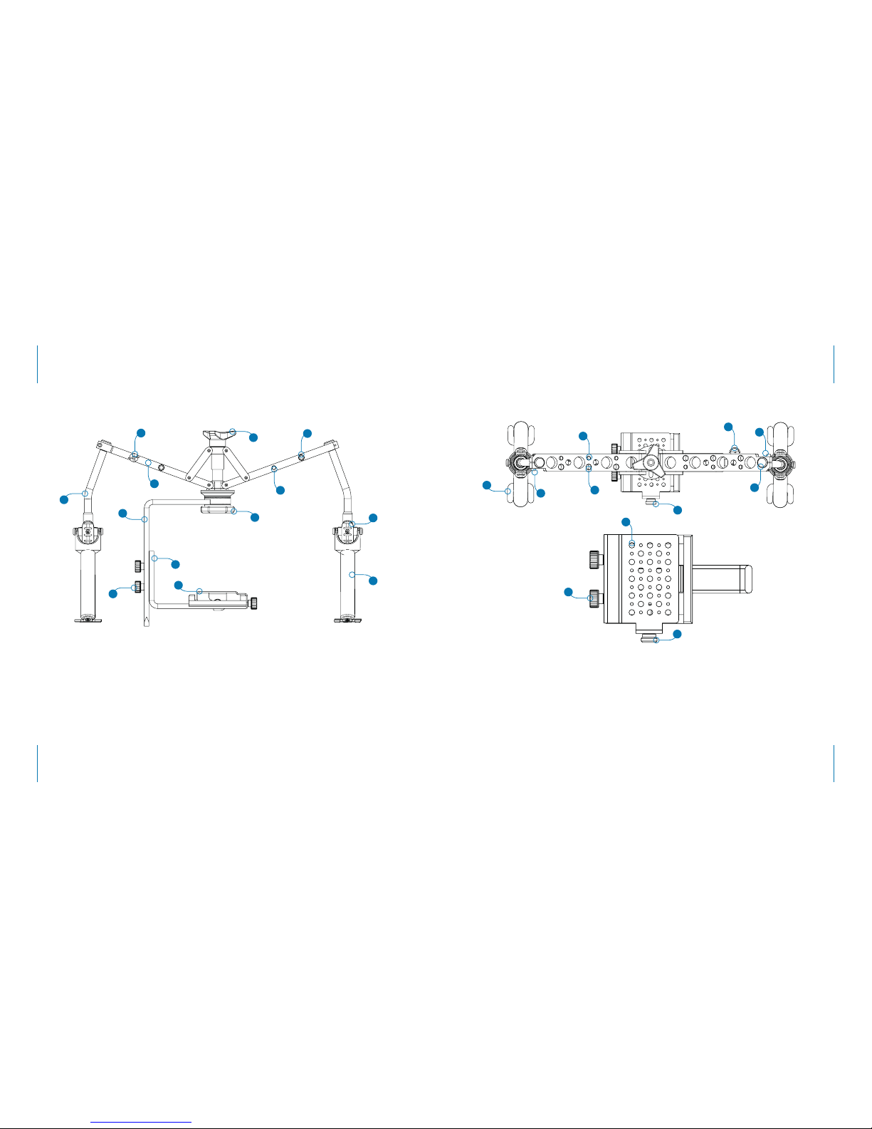
A Angled Support Post
B Upper Camera Support
C Lower Camera Support
D Height Adjustment Knobs
E Camera Mount Platform
F Camera Support Knob
G 1/4” Accessory Thread
H 3/8” Accessory Thread
I Adjustable Arm
J Vertical Adjustment Knob
K Hand Grip Gimbal
L Padded Hand Grip
M Post Extension Cover
N Post Removal Screw
O Camera Mount Screw
P 3/8” Accessory Thread
Q 1/4” Accessory Thread
R Base Foot
S Camera Screw Receiver
T Camera Platform Screw
U Horizontal Adjustment Knob
C
D
T
H
G
I
U
Q
P
N
R
O
N
M
O
Page 5
SET-UP: VERTICAL ADJUSTMENT & MOUNTING CAMERA SET-UP: BALANCING CAMERA
8 9
set-up: vertical adjustment & mounting camera set-up: balancing camera
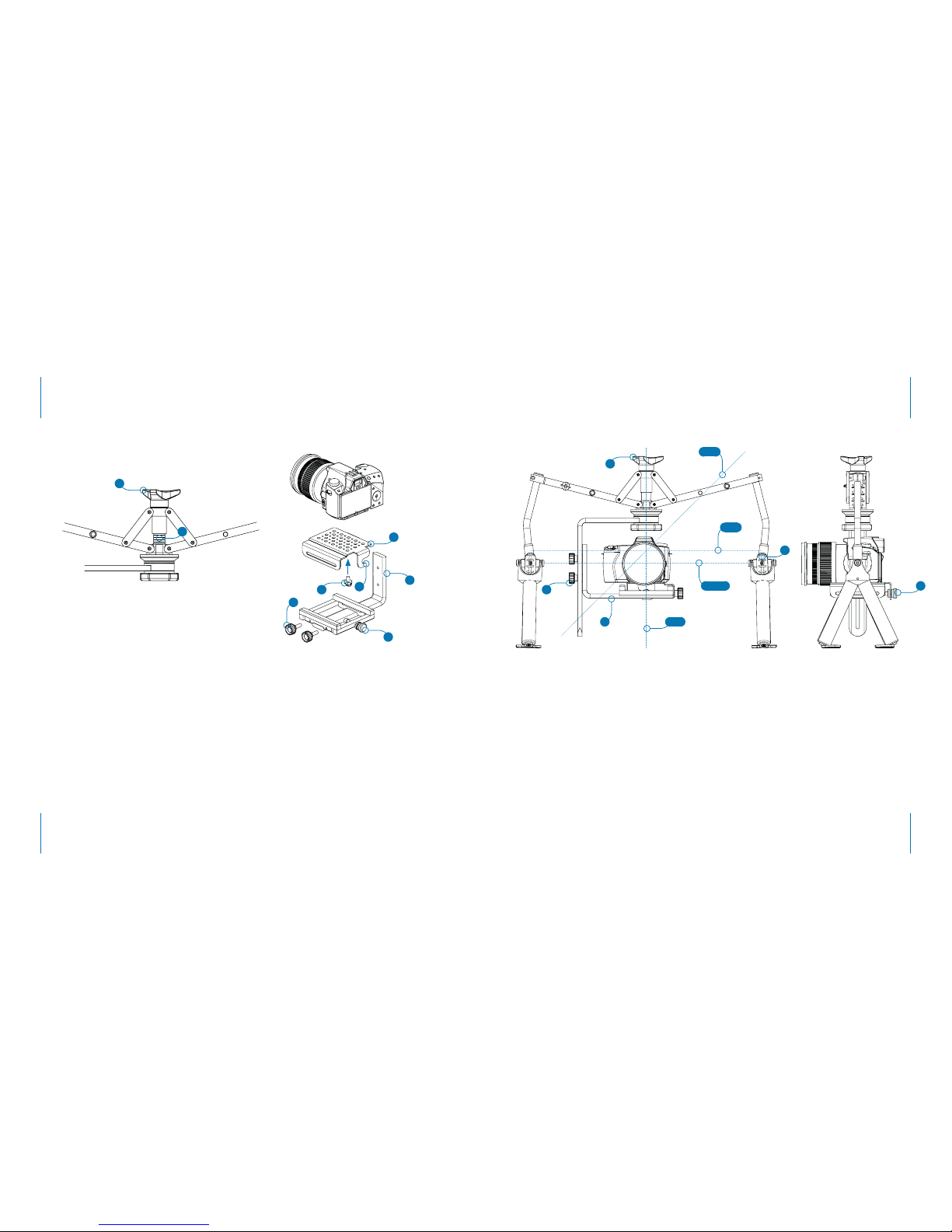
Once the mount plate is in place, connect
and tighten the ‘camera platform screws’
(T) to secure in place.
STEP 3...BALANCING CAMERA
The most important part of the Orbit setup is balancing your camera’s ‘centre-ofgravity’. The centre-of-gravity for each
camera will change and be dependant on
the specic lens used.
To balance the camera on the Orbit, the
Pivot-axis should be aligned with the X,
Y and Z-axis. The Pivot-axis is the axis
between the two ‘hand grip gimbals’ (K).
When the camera’s centre-of-gravity (X,Y
and Z-axis) is balanced along the Pivotaxis, you will be able to tilt the camera
forwards or backwards on the Orbit and
the camera will remain in position.
To balance the camera’s centre-ofgravity, rst adjust the ‘lower camera
support’ (C) to move the camera up or
down along the Y axis until somewhere
between the middle and top of the
cameras lens meets the Pivot-axis.
STEP 4...FINE-TUNE ADJUSTMENT
To ne-tune the balancing of the camera
use a combination of the ‘vertical
adjustment knob’ (J) and the ‘horizontal
adjustment knob (U)’.
First adjust the system vertically. If you tilt
the camera forwards or backwards and
it does not stay in position i.e. it swings
back in the opposite direction, it means
that the camera balance is either front
or back heavy and must be adjusted to
counter-balance the weight.
SET-UP...EASY AS ...
1...Vertical adjustment
2...Mounting camera
3...Balancing camera
4...Fine-tune adjustment
STEP 1...VERTICAL ADJUSTMENT
Before attaching your camera to the
Orbit ensure that the rig is placed onto
a at surface. Next, turn the ‘vertical
adjustment knob’ (J) until there are four
marker stripes visible (V). Doing this
before attaching your camera will allow
you equal vertical adjustment (up and
down) when ne-tuning the balancing of
your camera.
STEP 2...MOUNTING CAMERA
Connect your camera to the ‘camera
mount plate’ (E) using the provided
‘camera mount screw’ (O). The position
in which the camera is mounted to the
plate will be dependant on your chosen
camera and its specic centre-of-gravity;
usually the correct mounting position
will be the central hole or just behind the
central hole on the mount plate. You may
have to mount the camera a number of
times during the balancing procedure
before you nd the correct hole/mount
position for your specic camera. Once
your camera is attached to the mount
plate connect it to the ‘lower camera
support’ (C). When attaching the mount
plate to the lower camera support, you
must ensure that the ‘hook’ (W) on the
rear of the mount plate matches up with
the slot in the ‘horizontal adjustment
knob’ (U).
U
V
J
O
E
C
U
T
W
Y-Axis
Pivot-Axis
X-Axis
Z-Axis
J
T
K
C
Page 6
SET-UP: FINE-TUNE ADJUSTMENT USING EXTENSION ARMS
10 11
set-up: fine-tune adjustment using extension arms
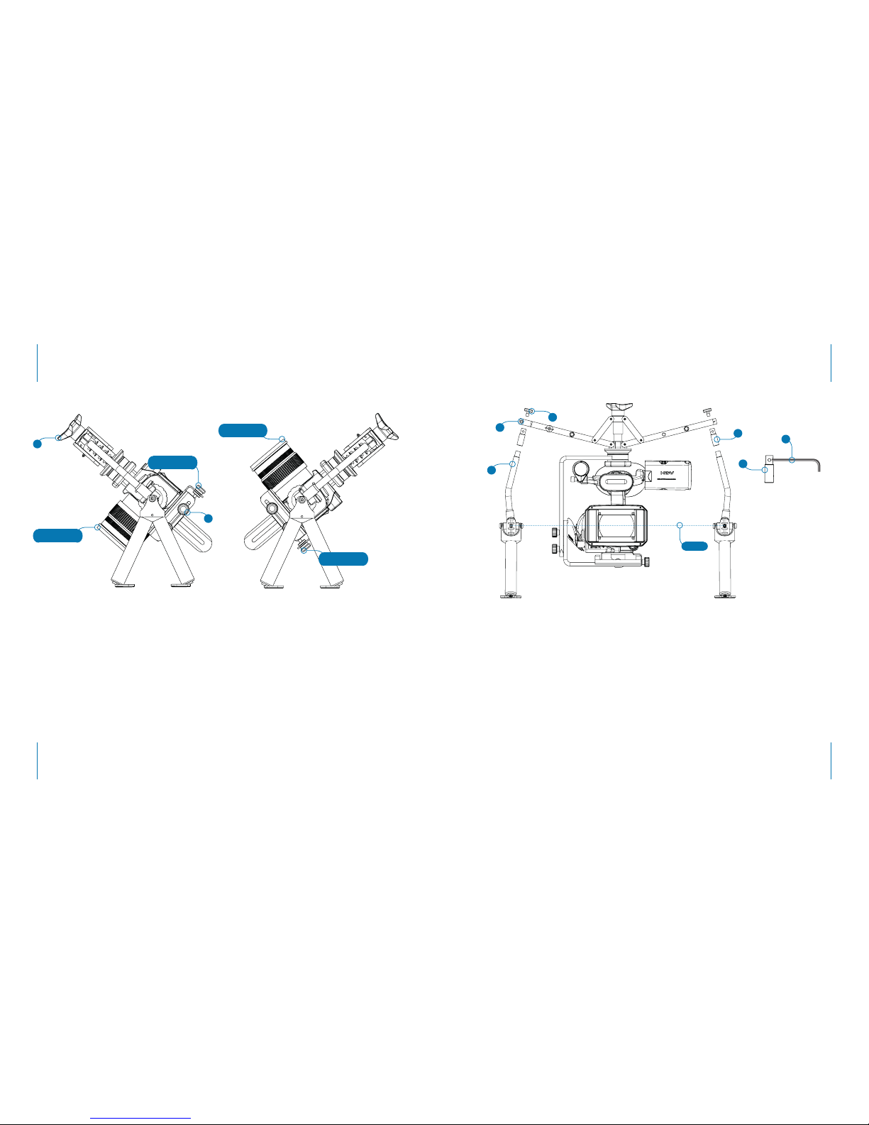
If (as shown in ‘Problem 1’) the lens is
tilting down, this means the camera is
front-heavy. To adjust the balance of the
camera, release the ‘camera platform
screws’ to loosen the tension of the
‘camera mount platform’, then turn the
horizontal adjustment knob (U) ‘anticlockwise’ to slide the camera (and
camera mount platform) backwards.
This will redistribute the weight and the
camera’s centre-of-gravity towards the
rear.
If (as shown in ‘Problem 2’) the camera
lens is tilting upwards, turn the horizontal
adjustment knob (U) ‘clockwise’ to slide
the camera (and camera mount platform)
forwards. This will redistribute the weight
and the camera’s centre-of-gravity
towards the front.
If you have adjusted your camera to
a position where it begins to tilt in the
opposite direction slowly, and with
minimal movement, after being moved
forward or backwards manually; tighten
the ‘camera platform screws’ (T) so they
lock the ‘camera mount platform’ in
place.
Next, use the ‘vertical adjustment screw’
(J) to make last ne-tune adjustments to
nd your cameras centre-of-gravity and
balance point.
By switching between the horizontal
and vertical adjustment screws you will
eventually nd your camera’s centre-ofgravity. Once balanced, your camera will
stay in position when tilted forwards or
backwards.
N.B. Set-up (mounting and balancing
camera) should take between 10-15
minutes.
Solution 1: Turn
‘U’ anti-clockwise
Problem 2: Lens
Pointing Up
Pivot-Axis
N
M
X
Problem 1: Lens
Pointing Down
Solution 2: Turn
‘U’ clockwise
NOTES...
Once the centre-of-gravity has been
found and the camera is balanced on the
Orbit, any adjustment to the camera will
unbalance the whole system.
For instance, changing the cameras
battery for a different kind or size will
alter the centre-of-gravity. Opening (or
closing) the cameras LCD view screen or
changing the lens will also have an affect
on and unbalance the centre-of-gravity.
USING...EXTENSION ARMS
If you are using a camera which is larger
than a traditional HD-DSLR or small
camcorder, you may need to use the
provided extension arms in order for the
lens to be seated along the pivot axis.
The Orbit is supplied with three different
size extension arms (25mm, 50mm and
75mm).
To t an extension arm to the Orbit rst
loosen the ‘post removal screw’ (N) using
the provided ‘Allen key’ (Y). Do not fully
remove the ‘post removal screw’. Once
the ‘post removal screw’ has been
loosened, unscrew and remove the ‘post
extension cover’ (M).
Next, insert the required ‘extension arm’
(X) and screw in place on top of the
‘angled support post’ (A). Tighten (or
loosen) an ‘extension arm’ to/from the
‘angled support post’ using the supplied
Allen key. Replace the ‘post extension
cover’ (M) and be sure to re-tighten the
‘post removal screw’ (N) before using the
Orbit.
X
Y
A
J
T
 Loading...