

Page 1

LBI-38915B
Maintenance Manual
MDX
896-941 MHz MOBILE RADIO
TABLE OF CONTENTS
RF Board........................................................... LBI-38545
System Board......................... .. .. .......................LBI-38842
Audio / Logic Board ......................................... LBI-38900
Audio Amplifier Board..................................... LBI-38844
Front Cap Assembly.......................... ...... ...... ...LBI-38850
PA Board........................................................... LBI-38547
Service Section ................................................. LBI-38912
Com-Net Ericsson Critical Radio Systems, Inc.
P.O. Box 2000
Lynchburg, Virginia 24501
1-800-528-7711 (Outside USA, 804-385-2400)
www.com-netericsson.com
Printed in U.S.A.
Page 2

Copyright© 1993-2001, Com-Net Ericsson Critical Radio Systems, Inc. All rights reserved.
TABLE OF CONTENTS
Page
SPECIFICATIONS........................................................................................................................................................ 1
GENERAL DESCRIPTION ......................................................................................................................................... 2
RF BOARD........................................................................................................................................................... 2
Synthesizer Circuit .......................................................................................................................................... 2
Transmit Circuit................. .. .. .......................... .......................... .......................... ............................................. 2
Receiver Circuit......................... ....................................................................................................................... 2
POWER AMPLIFIER BOARD ........................................................................................................................... 2
AUDIO/LOGIC BOARD..................................................................................................................................... 2
SYSTEM BOARD................................................................................................................................................ 2
FRONT CAP ASSEMBLY .................................................................................................................................. 2
ACCESSORIES AND OPTIONS.................................... ...... ...... .... ...... ...... ...... ...... ...... .... ...... ...... ...... ......................... 2
PC PROGRAMMER OPTIONS.......................................................................................................................... 2
PC PROGRAMMED OPTIONS.......................................................................................................................... 2
Carrier Control Timer (CCT) ........................................................................................................................... 2
Channel Guard.................................................................................................................................................. 2
Squelch Tail Elimination (STE) ....................................................................................................................... 3
HARDWARE AND HARDWARE OPTIONS.......................... .. .... .... .... .... .... .. .... .... .... .... .. .... .... .... .... .... .. .... .... ........... 3
OPTION CABLE.................................................................................................................................................. 3
NOISE SUPPRESSION K IT OPTION................................................................................................................ 3
POWER CABLE OPTION .................................................................................................................................. 3
EXTERNAL SPEAKER OPTION.................... .. .. .......................... .. .......................... ......................................... 3
EXTERNAL ALARM......................................... ............ .......... ............ ............ ............ ............ ........................... 3
SYSTEM DESCRIPTION............................................................................................................................................ 3
EDACS ................................................................................................................................................................. 3
CONVENTIONAL MODE..................................................... .. .. .. .. .. .. .. .. .. .. .... .. .. .. .. .. .. .. .. .. .. .. .. .. .... .. ..................... 4
RADIO OPERATION ................................................................................................................................................... 4
USER INTERFACE ......................... ................................................ .................................................................... 4
Turning the Radio ON/OFF ............................................................................................................................. 4
ALERT TONES............................................................................................................................................................. 4
EDACS APPLICATIONS .................................................................................................................................... 4
REPLACEMENT OF KEYCAPS........................................................................................................................ 4
PARTS LIST .............. ........................ ................................................ ............................................................................ 5
ASSEMBLY DIAGRAMS..................................... .. .. .......................... .. .......................... ............................................. 6
INTERCONNECT DIAGRAMS................................. .. .. .......................... .. .......................... ....................................... 9
Repairs to this equipment should be made only by an authorized service technician or facility designated by the supplier. Any repairs, alterations or substitution of recommended parts made by the user to this equipment not approved by the manufacturer could
void the user’s authority to operate the equipment in addition to the manufacturer’s warranty.
NOTE
This manual is publis hed by
Com-Net Ericsson Critical Radio Systems, Inc.
, without any warranty. Improvements and changes to this manual necessitated by
typographical errors, inaccurac ies of current information, or improvements to programs and/or equipment, may be made by
Com-Net Ericsson Critical Radio
Systems, Inc.
, at any time and wit hout notice. Such c hanges will be i ncorporated into new e ditions of this man ual. No part of this manual may be reproduced or
transmitted in any form or by any means, electronic or mechanical, including photocopying and recording, for any purpose, without the express written permission
of
Com-Net Ericsson Critical Radio Systems, Inc.
SPECIFICATIONS*
GENERAL
Regulatory Data
FCC AXATR-321-A2
DOC TR-321
Operating V oltage 13.6 Vo lts ±10%
Battery Drain
Receiver (13.8 Vdc)
Off 0.01 Amperes (maximum)
Squelched 0.80 Amperes (maximum)
Unsquelched 4.0 Amperes (maximum at 10 Watts audio,
External Speaker)
Transmitter (13.8 Vdc) 12.0 Amperes (maximum at 25 Watts RF)
Channel Spacing 12.5 kHz
Frequency Stability
±
1.5 PPM (±0.00015%)
Temperature Range -30° to +60°C (-22°F to +140°F)
Dimensions (H x W x D)
(Less Accessories)
Height 5.3 cm (2.1 inches)
Width 1 8.2 cm (7.2 inches)
Depth 24.0 cm (9.5 inches)
Weight 3.0 kg (6.6 pounds)
Antenna Impedance 50 Ohms
TRANSMITTER
Frequency Range
Trunked Conventional Repeater 896-902 MHz
Talkaround 935-941 MHz
Output Power 12.5-25 Watts (Intermittent duty cycle; E IA 20%)
Audio Sensitivity 90-120 mVrms (minimum)
Spurious and Harmonics <-16 dBm
Audio Distortion
<5% maximum
Modulation Limiting
±
2.5 kHz maximum
FM Noise -40 dB
Audio Frequency Response Within +1, -3 dB of a 6 dB/octave pre-emphasis curve
Per TIA/EIA Standards from 300-2300 Hz with additional 6dB/octave
2300-2700 and 12dB/octave from2700-3000 Hz
RECEIVER
Frequency Range 935-941 MHz
Acceptable Frequency Displacement
±
2.5 kHz minimum
Sensitivity (12 dB SINAD) -113 dBm minimum
Spurious Rejection 70 dB minimum
Adjacent Channel Selectivity 68 dB minimum at ±25.0 kHz
Intermodulation Distorti on 65 dB minimum (measurement per SP-2 218)
Audio Frequency Response Within +1, -3dB of a 6 dB/octave de-emphas is cur ve
from 500-2500 Hz
Audio Output 10 Watts (External Speaker); 4 Watts (Internal Speaker)
Audio Distortion 5% maximum at 1 kHz
Hum and Noise -45dB (unsquelched)
* These specifications are intended primarily for use by service personnel. Refer to the appropriate Specification Sheet for
complete specifications.
The software contained in this device is copyrighted by the Com-Net Ericsson Critical Radio Systems, In c. Unp ub lished
rights are reserved under the copyright laws of the United States.
NOTICE!
LBI-38915B
1
Page 3
GENERAL DESCRIPTION
The 900 MHz MDX Mobile Radio is a synthesized,
wideband radio that uses integrated circuits and microcomputer technology to pr ovide high performance trunked operation. This radio operates in the Enhanced Digital Access
Communications System (EDACS) environment, and in
conventional communication systems. The radio provides 25
Watts of RF power output in the 396-902 MHz and 935-941
MHz bands. The receiver operates in the 935-941 MHz
band.
All radio functions are stored in a programmable Electrically Erasable
PROM (EEPROM
). The radio is field programmable using an IBM compatible personal computer
with the following equipment:
•
Serial Programming Interface Module TQ3370
•
Programming Cable (19B801417P10) TQ3372
•
MDX Series Programming
Software (EDACS) TQ3365
With the interface equipment and software, the computer
can be used to program (or re-program) customer systemfrequencies, Channel Guard tones and options. Selection of options is done during radio initialization using the PC
programmer.
The 900 MHz MDX Mobile Radio assembly contains
the following circuit boards and assemblies:
•
Power Amplifier Board 19D902944Gxx
•
RF Board 19D902123Gxx
•
System Board 19D901891Gxx
•
Audio/Logic Board 19D903963Gxx
•
Audio Amplifier Board 19D904025Gxx
•
Front Cap Assembly 19D904151Gxx
The circuit boards are all mounted on a main casting to
provide easy access for servicing. Interconnect plugs are
used to connect the boards to eliminate pinched wires or
other wiring problems.
RF BOARD
The RF Board includes the programmable frequency
synthesizer, transmitter exciter, receiver front end and IF circuitry.
Synthesizer
The synthesizer circuit generates all transmit and receive
RF frequencies. The synthesizer frequency is controlled by
the microprocessor located on the Audio/Logic Board. Frequency stability is maintained by a temperature compensated
reference oscillator module. Transmit audio is processed on
the Audio/Logic Board and applied to the synthesizer to
modulate the VCO and TCXO. The buffered VCO output
drives both the transmitter exciter and the receiver mixer.
Transmitter
The transmitter consists of a fixed-tuned exciter module,
a PA module and a power control circuit. The PA module
provides RF output to drive the antenna. The power control
circuit controls the PA module to maintain a constant output
power across the band. The RF output level is internally adjustable for rated power. Thermistors in the control circuit
protect the PA from overheating by reducing the power output level.
Receiver
The dual conversion receiver circuit consists of a front
end section, 39.5 MHz first IF, a 455 kHz second IF, and FM
detector. All audio processing and squelch functions are accomplished on the Audio Board.
POWER AMPLIFIER BOARD
The PA board amplifies the RF board output then connects it back to the RF board where it is coupled through a
PIN diode antenna switch, the low-pass filter and the directional coupler to provide 25 watts of power output at the antenna connector.
AUDIO/LOGIC BOARD
The Audio/Logic Board provides all audio and digital
processing of the receive and transmit audio for digital processing by the Logic Board. The board also c on t ai n s a ud i o fi ltering, conventional analog tone processing, and the receiver
squelch. The Audio/Logic Board controls the operation of
the radio and digitally processes the receive and transmit
audio. The board contains a microprocessor and associated
memory circuits including an EPROM for controlling the
processor and a programmable "personality" memory (an
E
lectrically Erasable
PROM - EEPROM
) to store customer frequencies, tones and options. The microprocessor
provides control data to the Audio Signal Processor (
ASP
),
conventional tone generation and detection, frequency data
for the synthesizer, and sends and receives data to another
microprocessor on the Displa y Bo ard for the LCD.
SYSTEM BOARD
The system board controls the main input power to the radio. An IGNITION SENSE input lead provides the necessary
signals to the MOSFET switching circuit. The board also interfaces all option connections from the internal boards in the radio with the optional items outside of the radio. All external
options for the radio interconnect to the System Board through
the back of the radio using an optional cable.
FRONT CAP ASSEMBLY
The Front Cap Assembly contains the Audio Amplifier
Board. This board provides compression of the microphone
audio. It also provides audio compression for the received
audio in the discriminator and internal/external speaker audio
paths. A 10-watt power amplifier is provided on the board to
drive a 4-ohm internal/external speaker.
ACCESSORIES AND OPTIONS
PC PROGRAMMER OPTIONS
The radio is programmed using an IBM compatible personal computer equipped with a RS-232 port. Option TQ3370
provides the RS-232 serial interface unit and the cable between
the PC and the unit. An auxiliary power supply for the unit is
also included but is not needed to program the radio.
Option TQ3372 provides the radio programming cable between the PC interface unit and the radio microphone jack.
MDX PC programming software Option TQ3373 (EDACS) is
provided on 3.5 inch diskette s .
PC PROGRAMMED OPTIONS
Carrier Control Timer (CCT)
The Carrier Control Timer turns off the transmitter after the
microphone push-to-talk (PT T) switch has been keyed for a
pre-programmed time period. A pulsing alert tone warns the
operator to unkey and then rekey the PTT to continue the transmission. The timer can be programmed, using the PC programmer. Any time periods between 30 seconds and 7. 5 min utes can
be programmed in 30 second increments. The timer can be enabled or disabled for each channel.
Channel Guard
Channel Guard provides a means of restricting calls to specific radios through the use of a Continuous Tone Coded
Squelch System (CTCSS), or a Continuous Digital Coded
Squelch System (CDCSS). Tone frequencies range from 67.0
Hz to 210.7 Hz in 0.1 steps. There are eighty three standard PC
programmable digital codes. The Channel Guard tone fr eque ncies and codes are listed in
Table 1 - Channel Guard Tone
Frequencies
and
Table 2 - Digital Channel Guard Codes
(see below).
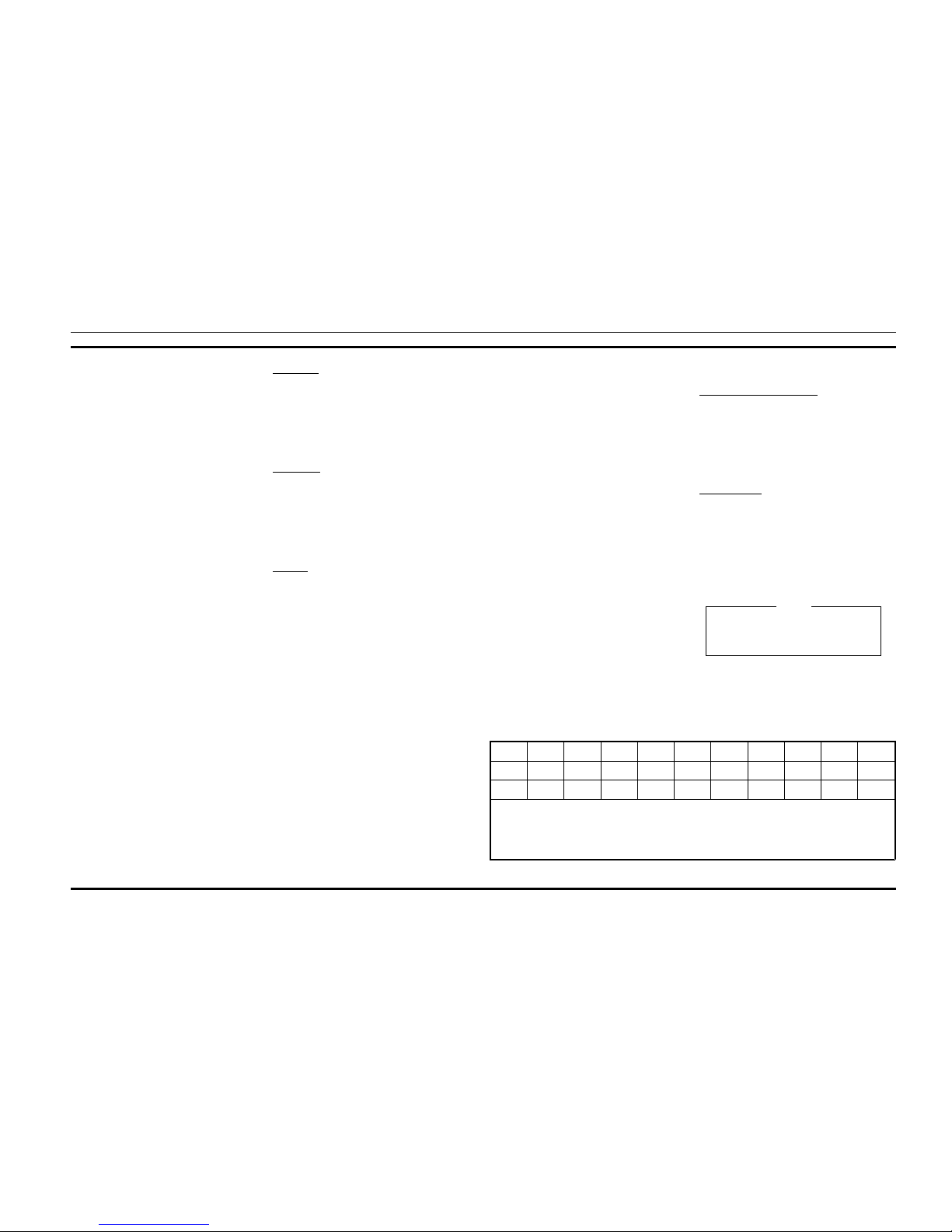
67.0 71.9 74.4 77.0 79.7 82.5 85.4 88.5 91.5 94.8 97.4
100.0 103.5 107.2 110.9 114.8 118.8 123.0 127.3 131.8 136.5 141.3
146.2 151.4 156.7 162.2 167.9 173.8 179.9 186.2 192.8 203.5 210.7
1. Do not use 179.9 Hz or 118.8 Hz in areas served by 60 Hz power distribution systems (or 100.0 Hz or 151.4 Hz in areas supplied with 50Hz power).
Hum modulation of co-channel stations may "false" Channel Guard decoders.
2. Do not use adjacent Channel Guard tone frequencies in systems employing multiple Channel Guard tones. Avoid same-areas co-channel use of adjacent
Channel Guard tones whenever possible. As stated in EIA Standard RS-220, there is a possibility of decoder falsing.
3. To minimize receiver turn-on time delay, especially in system using Channel Guard repeaters or receiver voting, choose the highest usable Channel
Guardtone frequency. Do not use tones below 100 Hz when it is necessary to meet the receiver response time requirements of EIA Standard RS-220.
Table 1 - Standard Tone Frequencies (Hz)
To reverse the polarity of the digital Channel Guard
codes, in the PC programmer, type I (inverted) before the code number, i.e. I023 .)
NOTE
LBI-38915B
2
Page 4
Squelch Tail Elimination (STE)
STE is used with tone and digital Channel Guard to eliminate squelch tails. The STE burst is transmitted when the microphone PTT is released. The receiving radio decodes the
burst and mutes the receiver audio for 250ms. This mute time
allows the transmission to end and to mute the squelch tail.
The radio looks for STE on the received signal when the mi-
crophone is either on or off-hook. The STE is enabled for
transmit and/or receive by PC programming the radio’s personality.
HARDWARE AND
HARDWARE OPTIONS
The location and placement of system hardware options
are shown on Sheet 4 of the 900 MHz MDX Mobile Interconnect Diagrams.
OPTION CABLE
Option Cable Option PMCD7Z (19C851585P18) is used
to bring all option connections from the System Board
through the back of the radio to the outside. This cable is required with all external options.
NOISE SUPPRESSION KIT OPTION
Noise Suppression Kit Option PMPD1A (consisting of
Filter 19A148539G1 and Installation Manual LBI-31363) is
available for installations where excessive alternator or electrical noises, present on the power cable, do not permit the
radio to operate properly. Refer to the interconnect diagram
for the radio and options.
POWER CABLE OPTION
18-foot Power Cable Option PMCD9A,
(19B801358P17), is available for installations requiring
more than the standard 9-foot cable.
EXTERNAL SPEAKER OPTION
External Speaker and Cable Option PMZM1T, provides
the user with a five-inch waterproof speaker in a LEXAN
housing. PMCC9M is an 18 inch interconnecting cable for
the speaker. The radio’s 10-watt amplifier drives the
speaker’s 4-ohm impedance. The speaker leads are connected to pins 2 and 9 of Option Cable Option PMCD7Z
(19C851585P18), using External Speaker Cable Option
PMCC9M (19A149590P8)(18 inches) included in the
PMZM5T kit. A 16-foot cable, Option PMCD1W
(19A149590P10) is also available.
EXTERNAL ALARM
External Alarm Horn Relay Option PMSU1C
(19A705499P1) can sound the vehicle horn when a call is
received. The option connects to pin 13 of Option Cable Option PMCD7Z (19C851585P18) and is controlled by a front
panel option switch.
SYSTEM DESCRIPTION
EDACS
The 900 MHz MDX Mobile Radio operates in EDACS
(digital) mode providing opportunities to increase RF channel utilization through faster channel access and the privacy
inherent with selective signalling.
The EDACS system uses 4800 baud, high speed, digital
signalling to identify individual units, user grou ps, fleets,
and agencies. Agencies contain multiple fleets and fleets
contain multiple user groups (sub-fleets). By using this addressing scheme large user groups can be accessed simultaneously all the way down to individual users. The
programming to det erm ine t ran smit encoded gr oups and de coded received groups is contained in the personality
EEPROM of the mobile radio. This information is individually programmed to suit each user’s needs via the PC programmer for the radio.
The typical system configuration consists of at least 2 repeater stations (with a maximum number of 25), and the associated mobiles. One repeater always is a control channel
dedicated to sending out continuous control data and also to
receive channel request data from the mobiles. When a mobile is first turned on it scans the available list of frequencies
programmed in the personality EEPROM for a control channel. When a control channel is found the mobile locks on to
the frequency and monitors the data for a channel assignment (incoming call).
When receiving a channel assignment (incoming call),
the monitoring mobile immediately switches over to the assigned voice channel and waits for a high speed data confirmation message. Upon receipt of this message the voice
paths are unmuted and the user can hear the call.
While on the voice channel, the mobile also continuously
monitors the low speed, 75 baud (subaudible) data and carrier noise squelch to ensure consistent operation. Upon loss
of subaudible data reception (i.e., deep fade, or out-ofrange), the mobile returns to the control channel frequency.
To initiate a call, the user keys the radio (which is locked
to the control channel), and a high speed data slotted channel
request is transmitted to the control channel receiver. The
control channel processes the request from the mobile and
transmits back a voice channel assignment on an unused
channel.
When all available voice channels are in use, the control
channel places the mobile into a queue, transmits a queue
message back to the mobile, and gives a channel assignment
to the requesting mobile as soon as a voice channel is free. If
the system is busy and the station queue is filled to capacity,
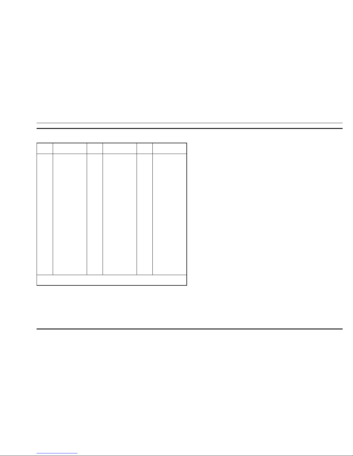
PRIMARY
CODE
EQUIVALENT
CODE
PRIMARY
CODE
EQUIVALENT
CODE
PRIMARY
CODE
EQUIVALENT
CODE
023
025
026
031
032
043
047
051
054
065
071
072
073
074
114
115
116
125
131
132
134
143
152
155
156
162
165
172
174
205
223
226
243
244
245
340 766
566
374 643
355
375 707
520 771
405 675
301
603 717 746
470 701
640
360 721
327 615
534 674
060 737
173
572 702
605 634 714
273
333
366 415
233 660
517 741
416 553
354
057
142 270
135 610
350 475 750
104 557
267 342
176 417
370 554
251
261
263
265
271
306
311
315
331
343
346
351
364
365
371
411
412
413
423
431
432
445
464
465
466
503
506
516
532
546
606
612
624
627
631
236 704 742
227 567
213 736
171 426
427 510 762
147 303 761
330 456 561
321 673
372 507
324 570
616 635 724
353 435
130 641
107
217 453 530
117 756
127 441 711
133 620
234 563 621 713
262 316 730
276 326
222 457 575
237 642 772
056 656
144 666
157 322
224 313 574
067 720
161 345
317 614 751
153 630
254 314 706
075 501
037 560
231 504 636 745
632
565
654
662
664
703
712
723
731
732
734
743
754
036
053
122
145
212
225
246
252
255
266
274
325
332
356
446
452
454
455
462
523
526
123 657
307 362
163 460 607
363 436 443 444
344 471 715
150 256
136 502
235 611 671
447 473 474 744
164 207
066
312 515 663
076 203
137
535
525
253
536
542 653
661
425
655
652
550 626
433 552
521
467 511 672
524 765
513 545 564
533 551
472 623 725
647 726
562 645
NOTE:
Primary codes in bold are unique Com-Net Ericsson codes.
Table 2 - Digital Channel Guard Codes
LBI-38915B
3
Page 5

a system busy message is returned to the requesting mobile
and an alert signal is given to the user.
After the initiating mobile receives a channel assignment
from the control station, it immediately switches frequency
over to the assigned voice channel and sends a burst of 4800
baud dotting. The microphone voice paths are then unmuted
and the transmission begins. The transmitting mobile also
continuously sends out a subaudible tone (along with voice)
for system reliability. If the station loses this signaling, the
voice channel is muted and all receiving mobiles are sent
back to the control channel.
In normal operation, the transmitting mobile sends a high
speed data burst to indicate that the user has unkeyed, causing all listening mobiles to switch back to the control channel.
CONVENTIONAL MODE
In conventional mode (not trunked) the radio can operate
either with tone Channel Guard, digital Channel Guard, or
carrier squelch, depending on personality programming.
Tone Channel Guard range is 67.0 to 210.7 Hz. Squelch Tail
Elimination (STE) is used with Channel Guard to eliminate
squelch tails at the receiving radio by phase shifting the
transmitted Channel Guard tone when the PTT is released.
Direct mode works identically to conventional mode except that the tr ansmit frequency band is chan ged to 935 to
941 MHz to permit direct mobile-to-mobile communications.
RADIO OPERATION
A complete set of operating instructions for the 900 MHz
MDX Radio are given in LBI-38914. This manual is provided with each radio.
This radio is flexible in operation and can be used in
either of two operating modes: Conventional radio system or
Enhanced Digital Access Communications (EDACS) system.
In an EDACS trunked environment the user selects a
communications system and group. In this mode, audio
channel selection is transparent to the user and is controlled
via digital communication with the system controller. This
mode incorporates advanced programmable features and fast
access to communication channels.
In Conventional mode, the user selects a channel and
communicates on that channel. In this mode, a system refers
to a set of channels and a channel is a transmit/receive radio
frequency pair .
The exact operation of any radio depends upon the operating mode, the programming of the radio and the particular
radio system. Most features described in these operating instructions can be enabled or disabled through programming.
Both of these important factors must be considered when addressing the following instructions.
USER INTERFACE
Operating controls are located on the radio front panel
and microphone.
The front panel LED provides radio status, and communication control information to the operator. The keypad is
used for manual number en try for i ndividu al calls, access to
a telephone interconnect system and activation of various
EDACS, and conventional features.
Turning The Radio ON/OFF
The radio is turned ON/OFF by pressing the PWR button
in the upper left corner of the front panel. A self diagnostic
test is performed when the radio is first turned on if enabled
through programming. To turn the radio OFF press the PWR
button again.
ALERT TONES
The 900 MHz MDX radio generates a set of unique
alert tones to indicate operating status. The following section
identifies and describes the alert tones used in the 900 MHz
MDX radio for Conventional and EDACS applications.
EDACS APPLICATIONS
CALL
ORIGINATE
ALERT
If programmed, a short tone is sounded
whenever the Push-To-Talk key is pressed
and the radio has acquired a channel. This
tone indicates the user can begin communications.
CALL
QUEUED
If one short, high-pit ched tone so unds after the transmitter is keyed, this indicates
that the system has placed the request in a
queue. This tone sounds at both the transmitting unit and the receiving unit(s), indicating to the user on the receiving end
that a call is being directed to them. If the
PTT is unkeyed while in the queue, the
radio autokeys (automatically keys) PushTo-Talk when a channel becomes available (see AUTOKEY).
AUTOKEY When the PTT is keyed to place a call on
the system, but the PTT is released before
getting to the channel (e.g. a queued call),
the radio automatically keys on the channel
when it gets the assignment. The radio generates a long beep and holds the transmitter
keyed for two seconds. Pressing the PTT
button keeps the channel and sends the message before this two second time-out has expired.
SYSTEM
BUSY
If you press the PTT key and hear three
short, medium-pitched tones, this indicates
that the receiving party is already on the
system or the system is busy and its queue is
full. You must rekey later to access the system.
CALL
DENIED
A single, low-pitched beep sounds when the
PTT key is pressed and the request is denied
by the system. This happens if the unit is an
invalid user or if the unit is requesting an
unavailable service.
OUT-OFRANGE/
SYSTEM
INOPERATIVE
A single, low-pitched tone sounds immediately after the PTT key is pressed indicating
the radio is out of range of the repeater. The
radio tries to place the call for a short period
(3 seconds) after the initial attempt. The radio generates a second low-pitched tone
when it gives up trying to place the call.
These tones may also heard ev en when the
radio is within calling range of the repeater
if the system is off the air or the radio needs
servicing.
REPLACEMENT OF KEYCAPS
The keycaps (SCN, A1, A2, MNU, SYS, CLR) can be replaced if damaged or if the function has changed by using the
keycap kit 344A4254G2. Included in this kit is a keycap extractor tool 19C852344P1. This extractor tool must be used to
remove keycaps to prevent damage to the key switches.
1. Align the extractor tool over the selected keycap, observ-
ing the alignment points on the keycap, and slide over
keycap until the tool is seated.
2. Squeeze the extractor tool to release the keycap from the
switch shaft and gently pull outward.
3. To replace a keycap, observe the correct alignment of the
keycap.
4. Push the keycap onto the switch shaft until it is seated.
LBI-38915B
4
Page 6

PARTS LIST
SYMBOL PART NO. DESCRIPTION
APPLICATION ASSEMBLY
19D902944
----------ASSEMBLIES----------
A1 19D902132G3 RF BOARD
A2 19D901891G3 SYSTEM BOARD
A3 19D904025G2 AUDIO AMPLIFIER BOARD
A4 19D903963G1 AUDIO/LOGIC BOARD
A5 19D902944G1 PA BOARD
A6 19D904151G1 FRONT CAP ASSEMBLY
----------KITS----------
344A4253G1 H ardware Kit (No. 1)
344A4255G8 H ardware Kit (No. 2)
344A4256G12 Hardware Kit (No. 3)
344A4254G1 Key Cap Kit
----------CABLES--------- -
19A705301P6 Cable, Antenna (W1)
19B801253P5 Cable, Ribbon (W 4)
19A705235P3 Cable, Ribbon, J 901 on Audio Amplifier to J902 on System
Board (W3)
19A704884P10 Cabl e Assembly, RF (W23)
19A704884P4 Cable Assembly, RF ( W22)
19B801467P1 Cable (W6)
19A704884P2 Cable Assembly, RF
----------MISCELLANEOUS--- -------
19D904027P1 Casting
19D904186G2 Cov er, Radio Top
19D904185G1 Cov er, Radio Bottom
Label, Microphone C9 C onnector
19B801398P5 Hanger, Microphone, Magnetic HSW LG
19B801358P18 Cable, 9 Foot, Power
344A4528P1 Microphone
344A4678P1 Hanger, Microphone (Used with Microphone 344A4528P1).
900 MHz MDX/ MOBILE RADIO ASSEMBLY
ISSUE 1
* COMPONENTS ADDED, DELETED OR CHANGED BY PRODUCTION CHANGES
LBI-38915B
5
Page 7
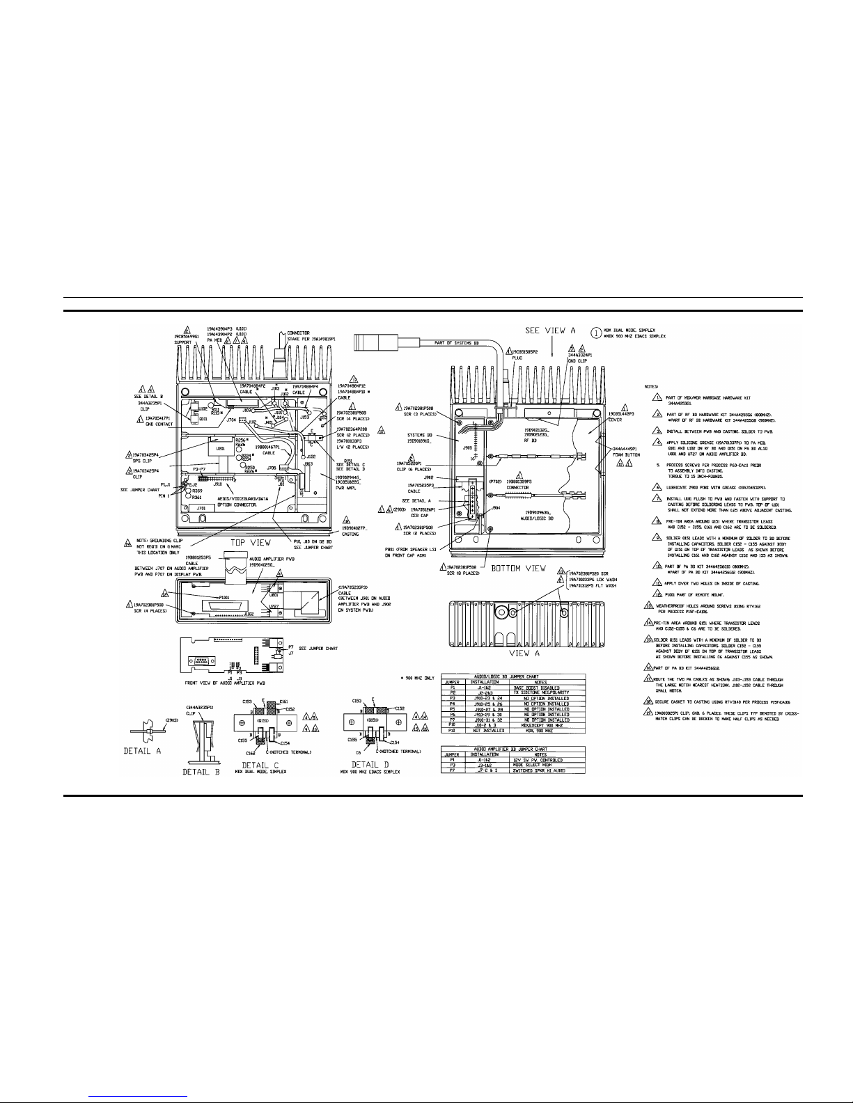
ASSEMBLY DIAG RAM
(19D904183, Sh. 1, Rev. 19)
LBI-38915B
6
Page 8
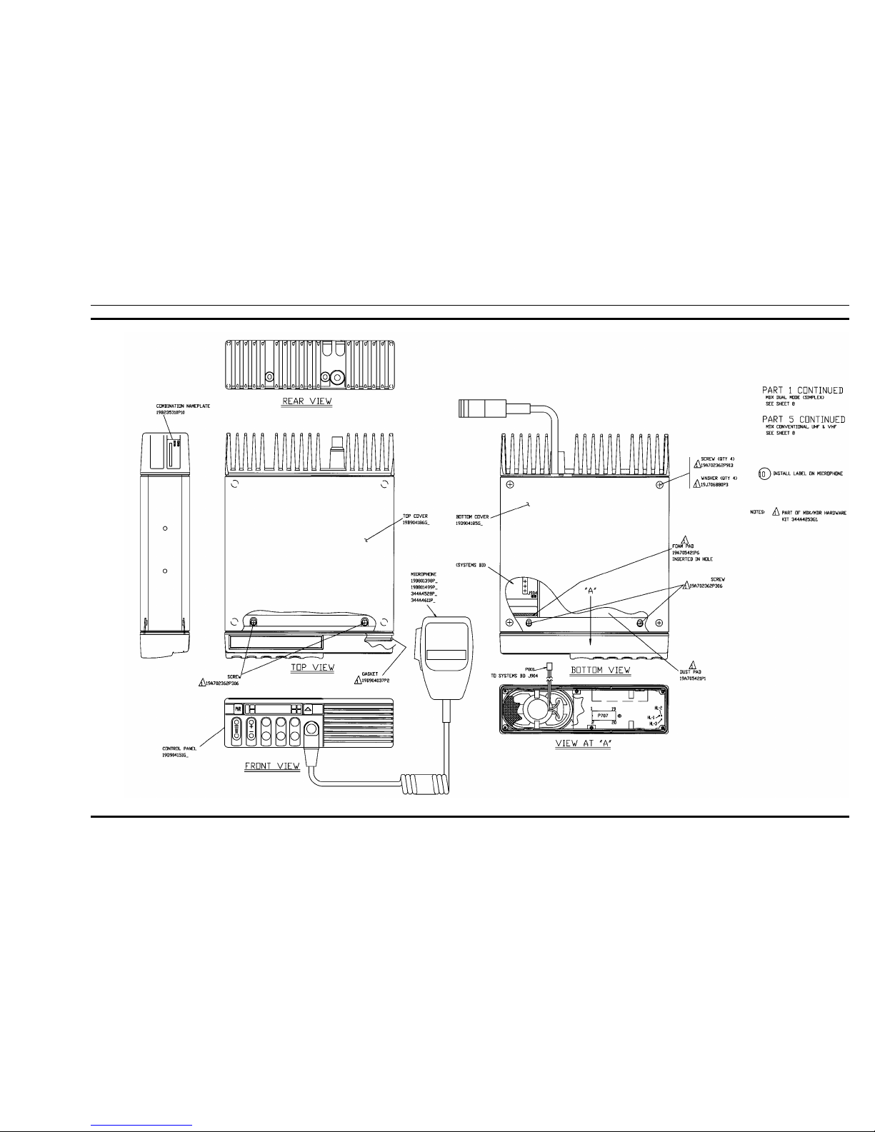
ASSEMBLY DIAGRAM
(19D904183, Sh. 2, Rev. 19)
LBI-38915B
7
Page 9
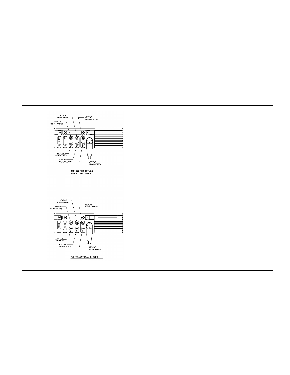
ASSEMBLY DIAG RAM
(19D904183, Sh. 5, Rev. 1)
LBI-38915B
8
Page 10
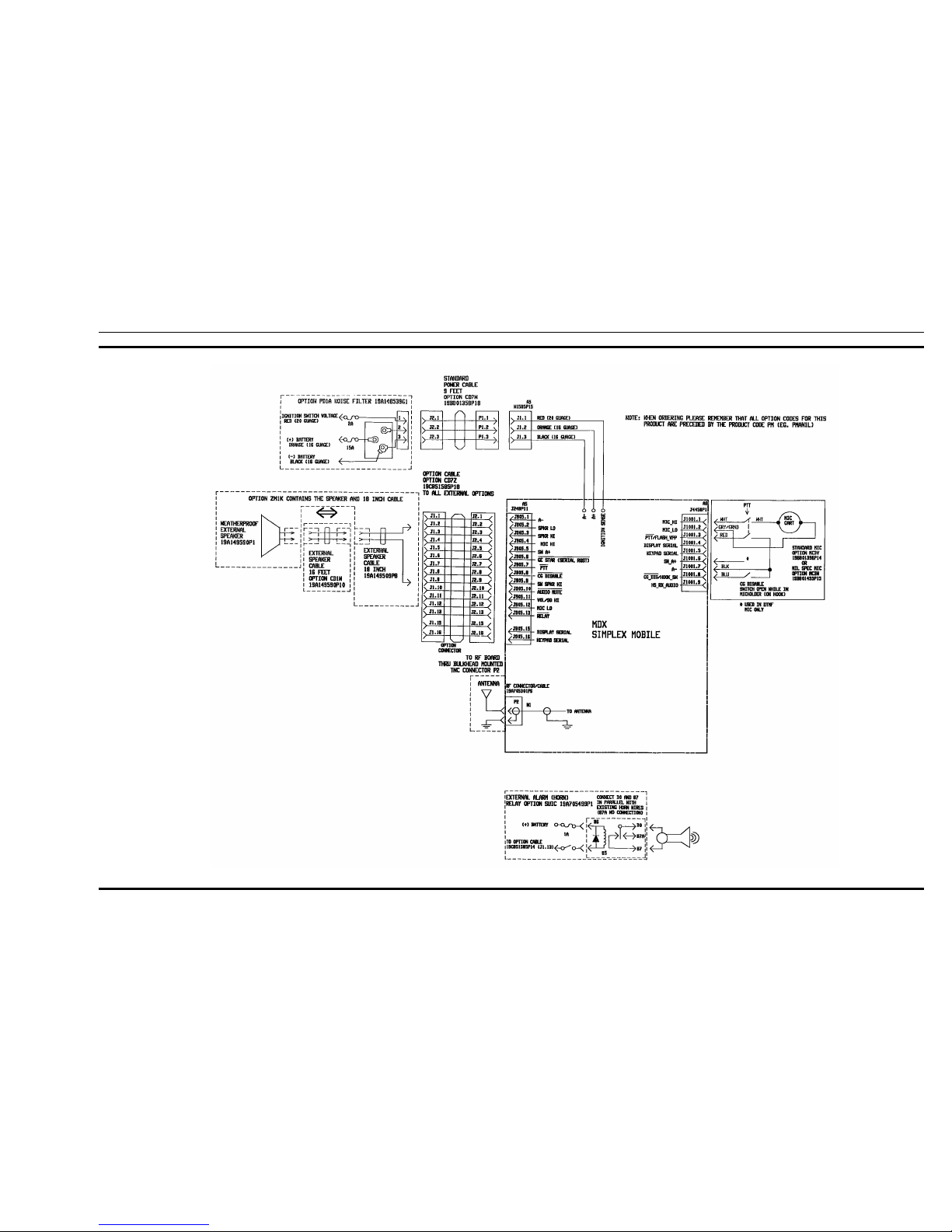
INTERCONNECT DIAGRAM
(19D904133, Sh. 1, Rev. 4)
LBI-38915B
9
Page 11
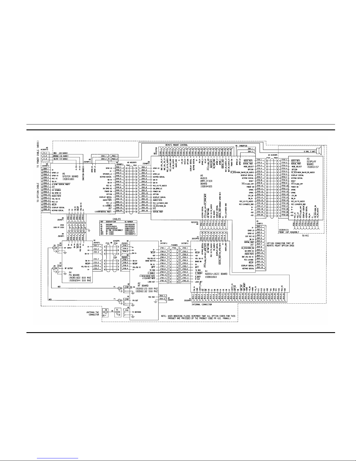
INTERCONNECT DIAGRAM
(19D904133, Sh. 2, Rev. 2)
LBI-38915B
10
Page 12
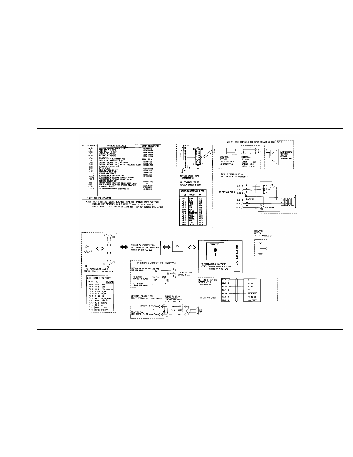
INTERCONNECT DIAGRAM
(19D904133, Sh. 3, Rev. 4)
LBI-38915B
11
 Loading...