

Comnet RLGE2FE16R-S-AC-288P, RLGE2FE16R-S-AC-288, RLGE2FE16R-S-AC-216, RLGE2FE16R-S-48-28-S22-CAN, RLGE2FE16R-S-12-28P-S22-CAN Quick Start Guide
...Page 1
QUICK START GUIDE
RLGE2FE16R
Substation-Rated, Enhanced Security Scada-Aware Ethernet
Layer 2 Managed Switch/Layer 3 Router With Optional 2G/3G
& 4G LTE Cellular Radio Link, Enhanced Network Security,
Terminal Server, PoE+, and 100FX SFP Ports
ComNet product series RLGE2FE16R are substation-rated and industrially hardened
layer 2 managed switches/layer 3 routers, with a unique and highly robust
packet processing SCADA-aware security firewall for the most mission-critical and
demanding cyber-security applications. The RLGE2FE16R is intended for deployment
in environments where high levels of electromagnetic noise and interference (EMI)
and severe voltage transients and surges are routinely encountered, such as electrical
utility substations and switchyards, heavy manufacturing facilities, track-side electronic
equipment, and other difficult out-of-plant installations. Layer 3 routing functionality
allows for the participation and foundation of a core network infrastructure.
The RLGE2FE16R is an ideal platform for deploying a secure communications and
networking gateway for remote electrical utility sites, and other critical infrastructure
applications.
Page 2

QUICK START GUIDE RLGE2FE16R
Contents
About This Guide 3
Intended Audience 3
Related Documentation 4
About ComNet 4
Website 4
Support 4
Safety 4
Overview 5
Hardware and Interfaces 5
Device walkthrough 6
Logical Structure 7
Distance kept for natural air flow 7
Grounding 7
Connecting to a Power Source 7
Wiring DC Input voltage feed 7
Wiring AC Input voltage connector 8
Power Budget 9
Configuration Environment 9
Management over Console 10
Connecting to Device 10
Terminal 10
SS H 11
Modes of Operation 12
Configuration through CLI 13
Create management VLAN 15
TECH SUPPORT: 1.888.678.9427
QSG_RLGE2FE16R_REV– 3 Aug 2016 PAGE 2
Page 3

QUICK START GUIDE RLGE2FE16R
About This Guide
This quick start guide includes relevant information for utilizing the Reliance RLGE2FE16R line of
switches.
The information in this document is subject to change without notice and describes only the
product defined in the introduction of this document.
This document is intended for the use of customers of ComNet only for the purposes of the
agreement under which the document is submitted, and no part of it may be reproduced or
transmitted in any form or means without the prior written permission of ComNet.
The document is intended for use by professional and properly trained personnel, and the
customer assumes full responsibility when using it.
If the Release Notes that are shipped with the device contain information that conflicts with the
information in this document or supplements it, the customer should follow the Release Notes.
The information or statements given in this document concerning the suitability, capacity, or
performance of the relevant hardware or software products are for general informational purposes
only and are not considered binding. Only those statements and/or representations defined in the
agreement executed between ComNet and the customer shall bind and obligate ComNet.
ComNet however has made all reasonable efforts to ensure that the instructions contained in this
document are adequate and free of material errors. ComNet will, if necessary, explain issues which
may not be covered by the document.
ComNet sole and exclusive liability for any errors in the document is limited to the documentary
correction of errors. ComNet is not and shall not be responsible in any event for errors in
this document or for any damages or loss of whatsoever kind, whether direct, incidental, or
consequential (including monetary losses), that might arise from the use of this document or the
information in it.
This document and the product it describes are the property of ComNet, which is the owner of all
intellectual property rights therein, and are protected by copyright according to the applicable laws.
Other product and company names mentioned in this document reserve their copyrights,
trademarks, and registrations; they are mentioned for identification purposes only.
Copyright © 2016 Communication Networks, LLC. All rights reserved.
Intended Audience
This user guide is intended for network administrators responsible for installing and configuring
network equipment. Users must be familiar with the concepts and terminology of Ethernet and
local area networking (LAN) to use this User Guide.
TECH SUPPORT: 1.888.678.9427
QSG_RLGE2FE16R_REV– 3 Aug 2016 PAGE 3
Page 4

QUICK START GUIDE RLGE2FE16R
Related Documentation
The following documentation is also available:
» RLGE2FE16R Data sheet
» RLGE2FE16R Installation and Operation Manual
» RLGE2FE16R_ES Enhanced Security Software Options Installation and Operation Manual
» SFP Modules Data sheet
About ComNet
ComNet develops and markets the next generation of video solutions for the CCTV, defense, and
homeland security markets. At the core of ComNet’s solutions are a variety of high-end video
servers and the ComNet IVS software, which provide the industry with a standard platform for
analytics and security management systems enabling leading performance, compact and cost
effective solutions.
ComNet products are available in commercial and rugged form.
Website
For information on ComNet’s entire product line, please visit the ComNet website at
http://www.comnet.net
Support
For any questions or technical assistance, please contact your sales person (sales@comnet.net) or
the customer service support center (techsupport@comnet.net)
Safety
» Only ComNet service personnel can service the equipment. Please contact ComNet Technical
Support.
» The equipment should be installed in locations with controlled access, or other means of
security, and controlled by persons of authority.
TECH SUPPORT: 1.888.678.9427
QSG_RLGE2FE16R_REV– 3 Aug 2016 PAGE 4
Page 5

QUICK START GUIDE RLGE2FE16R
Overview
Hardware and Interfaces
Depending on the RLGE2FE16R hardware variant ordered your switch will be equipped with a
combination of Fast Ethernet Ports, Gigabit Ethernet SFPs, Serial ports, and Cellular interfaces
» Serial RJ 45 ports supporting RS-232. Max 4 ports (Optional)
» Ethernet RJ45 copper 10/100 Fast Ethernet. (8 Standard, POE Optional) (Additional 8 10/100
ports optional, replaces cellular and serial)
» Ethernet SFP based ports,100/1000 GE. Max 2 ports (Standard)
» Ethernet SFP based ports 100 FE. Max 8 ports Additional. (Optional, replaces serial and cellular)
TECH SUPPORT: 1.888.678.9427
QSG_RLGE2FE16R_REV– 3 Aug 2016 PAGE 5
Page 6
QUICK START GUIDE RLGE2FE16R
10 11
1
4
8
2
3
5
9
6
13
7
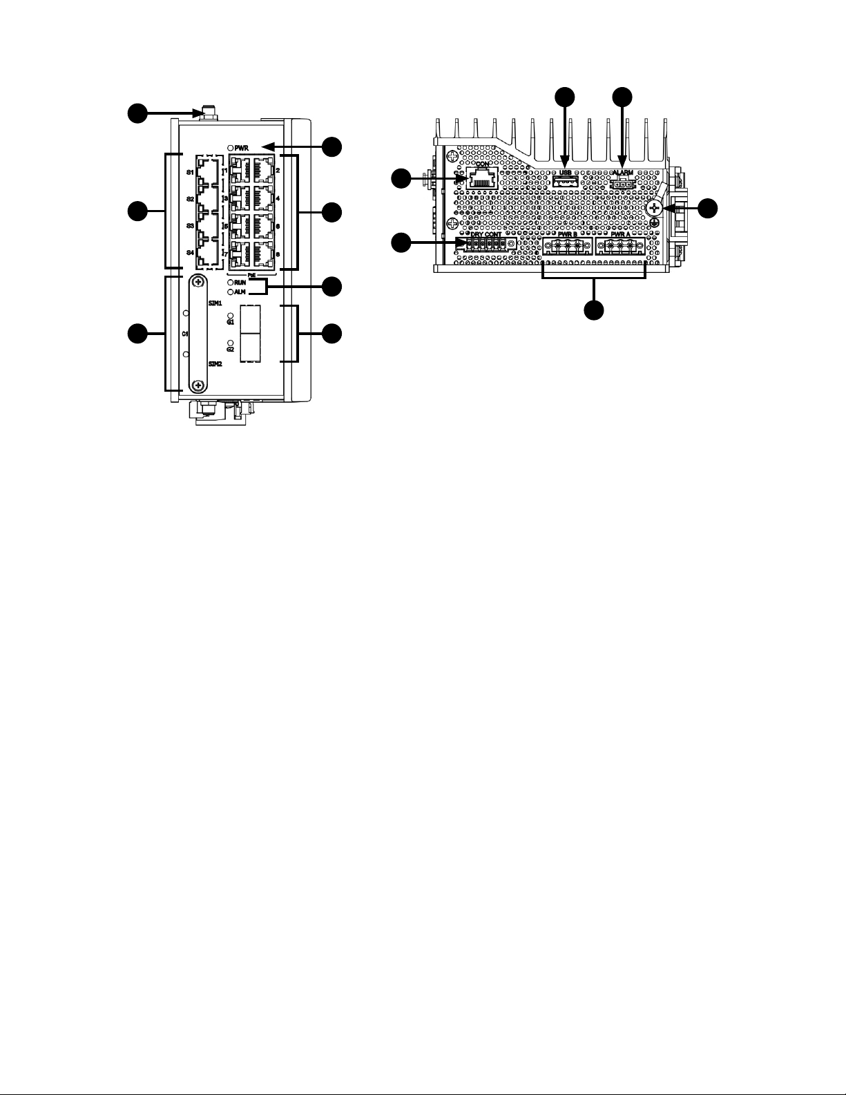
Figure 2 – R/S/22/28 Variant
12
Device walkthrough
» Ports Labeled 1 – 8 are Fast Ethernet capable of 10/100 FE capable ports with optional POE
capabilities.
» Ports Labeled S1-S4 are RJ45 ports with RS-232 support, establishing serial connections.
» Ports Labeled 9 & 10 are 100/1000 GE ports. They require SFPs in order to connect fiber/copper
interfaces. Many alternate SFP types are supported, including T1 lines, etc, please reach out to
support for testing inquirires before implementing any untested or non-ComNet SFP.
» Sim Slots 1 & 2 for cellular sim card placement.
» Port Labeled CON is communication port for serial console connections to device from PC.
» ANT for antenna placement.
» USB port for software upgrade.
» Power – AC or DC power supply needed depending on model.
TECH SUPPORT: 1.888.678.9427
QSG_RLGE2FE16R_REV– 3 Aug 2016 PAGE 6
Page 7

QUICK START GUIDE RLGE2FE16R
Logical Structure
Distance kept for natural air flow
Proper installation depends on natural air flow for cooling. You must maintain a 10cm distance
above and below the ComNet switch for proper air flow.
Grounding
To install the grounding wire:
» Prepare a minimum 10 American Wire Gauge (AWG) grounding wire terminated by a crimped
two-hole lug. Use a suitable crimping tool to fasten the lug securely to the wire. Adhere to your
company’s policy as to the wire gauge and the number of crimps on the lug.
» Apply some anti-oxidant onto the metal surface.
» Mount the lug on the grounding posts, replace the spring-washers and fasten the bolts. Avoid
using excessive torque.
CAUTION – Do not remove the earth connection unless all power supply connections are
disconnected.
DANGER – Before connecting power to the platform, make sure that the grounding posts are
firmly connected to a reliable ground, as described below.
Connecting to a Power Source
CAUTION – Please refer to the RLGE2FE16R installation guide for complete installation
instructions.
Wiring DC Input voltage feed
Input voltage can be either AC or DC depending on the specific module you purchased. Please
TECH SUPPORT: 1.888.678.9427
QSG_RLGE2FE16R_REV– 3 Aug 2016 PAGE 7
Page 8

QUICK START GUIDE RLGE2FE16R
take care to notice the label on the back of the module.
For the DC version there are 2 connection inputs, marked as “PWR A” and “PWR B”. For proper
operation it is only necessary to connect one power source, either to “PWR A” or to “PWR B”.
However, for redundancy purposes you may connect 2 different power sources one at “PWR A”
and the second to “PWR B”.
For wiring the voltage an opposite plug connector (2 pcs) is supplied.
Wiring AC Input voltage connector
For an AC product variant there is a single input connector.
Use a Brown wire for the Line (Phase) conductor, a Green/Yellow for the grounding and a Blue wire
for the Neutral conductor. Use 18AWG (1mm2) wire, with insulated ferrules.
TECH SUPPORT: 1.888.678.9427
QSG_RLGE2FE16R_REV– 3 Aug 2016 PAGE 8
Page 9

QUICK START GUIDE RLGE2FE16R
Power Budget
The following table details power consumption of the Hardware variants with cellular and serial
interfaces.
Unit Power feed Max Power [Watt] Version without POE ports Max Power [Watt] Version with POE ports
12 V D C 18.5 80
24 VDC 18.5 100
48 VDC 18.5 140
110 V D C 18.5 120
220 VDC 18.5 120
110 V A C 20.35 141
220 VAC 20.35 141
Configuration Environment
Two CLI based configuration environments are available for the user, these are:
» Global Configuration Environment (GCE)
» Application Configuration Environment (ACE)
These two environments are complementing each other and allowing each a set of supported
interfaces, network tools and management. At the RLGE2FE16R infrastructure, the GCE and ACE
are representing two different software processing areas. The physical and logical communication
between these areas are done by internal switching /routing using the Ethernet gigabit ports Gi
0/3 and Gi 0/4. These are known as the ACE ports.
For additional information about the ACE ports see chapter ACE ports.
TECH SUPPORT: 1.888.678.9427
QSG_RLGE2FE16R_REV– 3 Aug 2016 PAGE 9
Page 10

QUICK START GUIDE RLGE2FE16R
Management over Console
Connecting to Device
» Device is capable of being first set up via either the console port, or via an SSH connection
» Default Username: su
» Default Pass wor d: 1234
» By default all ports act as a flat switch, with all ports as members of VLAN 1
» VLAN 1 set to hold an IP interface by default
» Default Management IP: 10.0.0.1/8
Terminal
» Power on device (Boot may take up to 3 minutes). PWR light should be green
» Console into Device
› Connect to CON port using white ComNet Console Cable. Other console cables will not
work as they have a different pinout.
› Connect to to serial port of PC, or use Serial to USB cable. (Drivers may need to be installed)
› Terminal Serial Connection
1. Install and open terminal software
2. Setup terminal for serial session
3. Determine correct COM port on PC (Device manager)
4. Enter correct COM port, enter correct baud rate speed (Default 9600)
5. Click Open to start session with device
› Press enter if screen is blank
› Default login username su, password 1234 (password will be invisible)
TECH SUPPORT: 1.888.678.9427
QSG_RLGE2FE16R_REV– 3 Aug 2016 PAGE 10
Page 11

QUICK START GUIDE RLGE2FE16R
SSH
» SSH Connection to RLGE2FE16R
› Setup PC network to be on the same as the default management network
» Example PC Setup:
› IP Address of PC: 10.0.0.51
› Subnet mask: 255.0.0.0
› Gateway: 10.0.0.1 (Optional)
› Ping management VLAN IP: 10.0.0.1
› From any terminal session type: ssh su@10.0.0.1
› Default login username su, password 1234 (password will be invisible)
TECH SUPPORT: 1.888.678.9427
QSG_RLGE2FE16R_REV– 3 Aug 2016 PAGE 11
Page 12

QUICK START GUIDE RLGE2FE16R
Modes of Operation
ACE vs GCE
GCE interface used for
» IP Management to switch (SSH, Terminal, SNMP, FTP)
» Routing of access traffic using static entries or OSPF
» Mainly used for Switching (Vlans, Interface Troubleshoot, System information, etc.)
ACE interface used for
» Layer 3 configurations (Firewalls, Cellular, Routing, IPSEC, DMVPN,etc.)
» Access Control Lists
» Authentication-Proxy
» Event Logger
Command Mode Access Method Prompt Exit Method Usage
Root Following user log in RLGE2FE16R # User needs to log
out using command
logout or exit
Global Configuration
Environment (GCE)
Global Hierarchy
Configuration
Application
Configuration
Environment (ACE)
Application Hierarchy
Configuration
Command Configure Terminal RLGE2FE16R(config)# Return to root mode
using command exit
or end
From Global Configuration
mode you can access sub
tree feature. Ex. Interface
configuration sub tree
Use the “application connect”
from the root mode to enter
the application configuration
area
From application root you can
access sub tree feature. Ex.
Router interface
RLGE2FE16R(config-if)# Return to global
config using
command exit
[/] Exit to root mode
using exit and
pressing enter to see
prompt
[router/interface] To go back to root of
application you must
type two dots (..) and
press enter
Issue Show
commands
Issue configurations
Deep configurations
of device ranging
from inter face to
routing, etc.
Global Configuration
of the ACE
Deep configurations
of device ACE
ranging from cellular
to VPN, etc.
TECH SUPPORT: 1.888.678.9427
QSG_RLGE2FE16R_REV– 3 Aug 2016 PAGE 12
Page 13

QUICK START GUIDE RLGE2FE16R
Configuration through CLI
At any point of operation you can type ? to get a listing of all available options
At any point of typing a command you can press tab to complete a word.
Check device software/firmware version typing Show System information (pressing q will end the
listing when it shows --more-- , space will continue the page)
RLGE2FE16R# show system information
Hardware Version : 0202
Firmware Version : 3.5.04.32 U-Boot 2010.12 (Dec 11 2012 - 10:34:29)
Hardware Part Number : RLGE2FE16R/S/12/28/S22/CEU_________
____________________
System Name : Switch software version 3.5.04.32
System Contact : Not Specified
System Location : Not Specified
Logging Option : Console Logging
Login Authentication Mode : Local
Config Save Status : Successful
Remote Save Status : Not Initiated
Config Restore Status : Not Initiated
Traffic Separation Control : none
Board Serial Number : 1600265635
Manufacture Serial Nu m b er : 1111111111
Assembly Number : 00265635
Hardware Revision : 0202
HW sub-type : 2239
CLEI : FFFFFFFFFFFFFFFF
M AC ad d r ess : 00:22:3B:11:22:33
License value : 000000000000
Device Type ID : <null>
Part Number 2 : RLGE2FE16R/S/12/28/S22/CEU_________
TECH SUPPORT: 1.888.678.9427
QSG_RLGE2FE16R_REV– 3 Aug 2016 PAGE 13
Page 14

QUICK START GUIDE RLGE2FE16R
Check VLAN (Virtual LAN) interface using show vlan to see ports associated to vlan
RLGE2FE16R# show vlan
Switch defau lt
Vlan database
------------Vlan ID : 1
Member Ports : Fa0/1, Fa0/2, Fa0/3, Fa0/4, Fa0/5, Fa0/6
Fa0/7, F a 0/8, G i0/1, Gi0/2, Gi0/3, G i0/4
Untagged Ports : Fa0/1, Fa0/2, Fa0/3, Fa0/4, Fa0/5, Fa0/6
Fa0/7, F a 0/8, G i0/1, Gi0/2
Forbidden Ports : None
Name :
Status : Permanent
---------------------------------------------------Vlan ID : 4091
Member Ports : Gi0/1, Gi0/2, Gi0/3, Gi0/4
Untagged Ports : None
Forbidden Ports : None
Name :
Status : Permanent
---------------------------------------------------Vlan ID : 4092
Member Ports : Gi0/3, Fa0/10, Fa0/11
Untagged Ports : Fa0/10, Fa0/11
Forbidden Ports : None
Name :
Status : Permanent
---------------------------------------------------Vlan ID : 4093
Member Ports : Gi0/3
Untagged Ports : None
Forbidden Ports : None
Name :
Status : Permanent
---------------------------------------------------Vlan ID : 2
Member Ports : Fa0/1
Untagged Ports : Fa0/1
Forbidden Ports : None
Name :
Status : Permanent
----------------------------------------------------
RLGE2FE16R#
TECH SUPPORT: 1.888.678.9427
QSG_RLGE2FE16R_REV– 3 Aug 2016 PAGE 14
Page 15

QUICK START GUIDE RLGE2FE16R
Check Vlan IP addresses by typing show ip interface
RLGE2FE16R# show ip interface
vlan1 is up, line protocol is up
Int er ne t A dd r es s is 10.0.0.0/8
Br o a d c as t A d d r ess 10.0.0.255
Create management VLAN
Give management VLAN an IP address
» Enter global configuration mode by typing Configure Terminal in the command line you will
see RLGE2FE16R(config)#
» Enter vlan interface you wish to set an IP address for (Format will be ip address (a) subnet mask
(b) a.a.a.a b.b.b.b)
» Followed by no shutdown command to make sure vlan is not shut down
› Exit will be used to exit the interface
› Now you set up layer 2. Enter Vlan x and add ports to the vlan.
› Once done, use end to exit back to root mode
› Enter wr st (write startup) to save all configurations
RLGE2FE16R(config)# interface vlan 1
RLGE2FE16R(config-if)# ip address 10.10.10.1 255.255.255.0
RLGE2FE16R(config-if)# no shutdown
RLGE2FE16R(config-if)# exit
RLGE2FE16R(config)# vlan 1
RLGE2FE16R(config-vlan)# ports fastethernet 0/1-8 gigabitethernet 0/3 untagged fastethernet
0/1- 8
RLGE2FE16R(config-vlan)# end
RLGE2FE16R# wr st
Building configuration ...
[OK]
% startup-config saved successfully
RLGE2FE16R# █
» You now need to add ports to specific vlans.
› Enter into global config once again (Conf t)
› Enter the interface you wish to add to the vlan and set Port vlan ID to the vlan number
TECH SUPPORT: 1.888.678.9427
QSG_RLGE2FE16R_REV– 3 Aug 2016 PAGE 15
Page 16

QUICK START GUIDE RLGE2FE16R
RLGE2FE16R(config)# interface fastethernet 0/1
RLGE2FE16R(config-if)# switchport pvid 1
RLGE2FE16R(config-if)# end
RLGE2FE16R# wr st
Building configuration ...
[OK]
% startup-config saved successfully
RLGE2FE16R# █
» End to exit global config mode
» Finish by saving configurations
An example of more in depth management interface assignment can be found in the RLGE2FE16R
Installation and Operation Manual under the section “Management>Example”
TECH SUPPORT: 1.888.678.9427
QSG_RLGE2FE16R_REV– 3 Aug 2016 PAGE 16
Page 17

QUICK START GUIDE RLGE2FE16R
TECH SUPPORT: 1.888.678.9427
QSG_RLGE2FE16R_REV– 3 Aug 2016 PAGE 17
Page 18

QUICK START GUIDE RLGE2FE16R
ComNet Customer Service
Customer Care is ComNet Technology’s global service center, where our
professional staff is ready to answer your questions at any time.
Email ComNet Global Service Center: customercare@comnet.net
3 CORPORATE DRIVE | DANBURY, CT 06810 | USA
T: 203.796.5300 | F: 203.796.5303 | TECH SUPPORT: 1.888.678.9427 | INFO@COMNET.NET
8 TURNBERRY PARK ROAD | GILDERSOME | MORLEY | LEEDS, UK LS27 7LE
T: +44 (0)113 307 6400 | F: +44 (0)113 253 7462 | INFO-EUROPE@COMNET.NET
© 2016 Communications Networks Corpor ation. All Right s Reserved. “ComNet” and
the “ComNet Logo” are registered trademarks of Communication Networks, LLC.
QSG_RLGE2FE16R_REV– 3 Aug 2016 PAGE 18
 Loading...