

Page 1
INSTALLATION AND OPERATION MANUAL
RLGE2FE16R
Substation-Rated, Enhanced Security Scada-Aware Ethernet
Layer 2 Managed Switch/Layer 3 Router With Optional 2G/3G
& 4G LTE Cellular Radio Link, Enhanced Network Security,
Terminal Server, PoE+, and 100FX SFP Ports
ComNet product series RLGE2FE16R are substation-rated and industrially hardened
layer 2 managed switches/layer 3 routers, with a unique and highly robust
packet processing SCADA-aware security firewall for the most mission-critical and
demanding cyber-security applications. The RLGE2FE16R is intended for deployment
in environments where high levels of electromagnetic noise and interference (EMI)
and severe voltage transients and surges are routinely encountered, such as electrical
utility substations and switchyards, heavy manufacturing facilities, track-side electronic
equipment, and other difficult out-of-plant installations. Layer 3 routing functionality
allows for the participation and foundation of a core network infrastructure.
The RLGE2FE16R is an ideal platform for deploying a secure communications and
networking gateway for remote electrical utility sites, and other critical infrastructure
applications.
Page 2

INSTALLATION AND OPERATION MANUAL RLGE2FE16R
Contents
About This Guide 14
Intended Audience 14
Related Documentation 15
About ComNet 15
Website 15
Support 15
Safety 15
Overview 16
Introduction 16
Key Features 16
Hardware and Interfaces 19
Graphic View of Hardware 22
22
Distance kept for natural air flow 23
Logical Structure 24
Grounding 24
Connecting to a Power Source 25
Power Budget 26
Management over Console 26
Connecting to Device 26
Terminal 27
SSH 28
Configuration Environment 29
Command Line Interface 29
Command Line navigation 30
Dynamic Completion of Commands 31
TECH SUPPORT: 1.888.678.9427
Help (?) 31
Keyboard Shortcuts 32
Supported Functionalities 33
System Default state 36
Root Commands 37
Root Commands Description 38
GCE Commands 39
INS_RLGE2FE16R_REV– 10 Aug 2016 PAGE 2
Page 3

INSTALLATION AND OPERATION MANUAL RLGE2FE16R
GCE Commands Description 42
ACE Commands 46
Main Show Commands 47
System Version and Data Base 51
Configuration Database 51
OS VERSION 52
Running Configuration 53
Example upgrade the OS from USB 54
Example upgrade the OS from SFTP 55
Example export db and logs 56
Example handling DB files on flash 56
Example Import DB from TFTP 57
Safe Mode 58
SW Image upgrade and Recovery 59
Install OS image update from a USB 60
Installing First OS image from a USB 64
System Database Import/ Export 65
Port Interfaces 68
Port addressing 68
A Logical View Of Ports 68
Enabling Ports 69
ACE Ports 69
Default state 69
Vlan assignment 70
Ports FE 0/9-0/16 70
POE Ports 71
Power Management of POE 72
Mode of PoE 72
POE command Hierarchy 73
Controlling Ports 74
Ports command Hierarchy 74
TECH SUPPORT: 1.888.678.9427
POE Commands Description 73
Storm Control 74
Rate Limit Output 74
INS_RLGE2FE16R_REV– 10 Aug 2016 PAGE 3
Page 4

INSTALLATION AND OPERATION MANUAL RLGE2FE16R
Port Commands Description 75
Port Configuration Example 77
Configuration Output Example 77
Login and Management 79
Login Authentication Hierarchy 79
Login Authentication Commands Description 80
Examples 81
Privilege level 82
Commands Description 82
Serial Console Port 83
Connecting to the Console Port 83
CLI Console Commands 84
Management 84
Commands Hierarchy 85
Commands Description 87
System Alias 89
CLI Pagination 90
MAC-Address Table (FDB) 91
Port Mac Learning and limit 91
Commands Hierarchy 91
Configuration Example, Static MAC entry 92
Example, exceeding MAC limit at a port 92
IP ARP Table 93
Commands Hierarchy 93
Commands Description 93
Configuration Example 94
VLAN 95
VLANs of System Usage 96
TECH SUPPORT: 1.888.678.9427
VLAN Range of NMS Usage 96
VLAN Configuration Guidelines 96
VLAN Default State 96
Vlan Ports 97
Enabling VLAN 97
Vlan command Hirarchy 98
INS_RLGE2FE16R_REV– 10 Aug 2016 PAGE 4
Page 5

INSTALLATION AND OPERATION MANUAL RLGE2FE16R
IP Interfaces 101
GCE IP Interfaces 101
Commands Hierarchy 102
Commands Description 103
Default state 103
Static and Dynamic switch Default IP Address assignment 105
ACE IP Interfaces 106
ACE IP Interface Commands Hierarchy 107
ACE IP Interface Commands Description 107
Example for creating ACE IP Interface 108
Diagnostic 109
System Environment 109
RMON 110
System logs export 112
Commands Hierarchy 112
Capture Ethernet service traffic 113
Commands Hierarchy 113
Commands Description 114
Example 114
DDM 115
Debugging 119
Commands Hierarchy 119
Commands Description 120
Syslog 120
The Priority indicator 121
GCE Message Format 122
ACE Message Format 122
ACE Message severity 122
Firewall TCP SCADA Protocols 123
TECH SUPPORT: 1.888.678.9427
Firewall Serial SCADA Protocols 124
DM-VPN logs 127
Cellular logs 128
Alarm Relay logs 130
Commands Hierarchy 131
Commands Description 132
INS_RLGE2FE16R_REV– 10 Aug 2016 PAGE 5
Page 6

INSTALLATION AND OPERATION MANUAL RLGE2FE16R
Configuration Example 133
Output example 134
Alarm Relay 135
ALARM Interface 135
Supported Alarms 138
Commands Hierarchy 139
Commands Description 140
Monitor Session 141
Commands Hierarchy 141
Commands Description 141
ACE Watchdog 141
Commands Hierarchy 142
Commands Description 142
SNMP 143
Supported traps 143
SNMP command Hierarchy 143
SNMP Command Description 144
Clock and Time 148
Local Clock 148
Commands Description 149
SNTP 150
SNTP Commands Descriptions 151
SSH 156
SSH Command Hierarchy 156
SSH Commands Descriptions 157
DHCP Client and Snooping Commands Hierarchy 158
DHCP Server 159
DHCP Server Commands Hierarchy 159
TECH SUPPORT: 1.888.678.9427
DHCP Relay Commands Description 160
Example 161
DHCP Client 162
DHCP Server show outputs 162
INS_RLGE2FE16R_REV– 10 Aug 2016 PAGE 6
Page 7

INSTALLATION AND OPERATION MANUAL RLGE2FE16R
DHCP Relay 165
DHCP Relay GCE Command Hierarchy 165
DHCP Relay GCE Commands Description 166
DHCP Relay ACE Command Hierarchy 167
DHCP Relay ACE Commands Description 168
Example, GCE DHCP Relay 169
RADIUS Command Hierarchy 173
RADIUS Commands Descriptions 174
TACACS 176
Default Configurations 177
TACACS Command Hierarchy 177
TACACS Commands Descriptions 178
Configuration Example 179
802.1x 180
802.1x Commands Hierarchy 180
802.1x Commands Descriptions 181
Examples 183
IGMP Snooping 185
IGS Commands Hierarchy 185
IGS Commands Descriptions 186
Example 188
AC Ls 190
ACL Flow validation at a port 190
ACL Commands Hierarchy 192
ACL Commands Descriptions 193
QOS 205
QOS Commands Hierarchy 205
QOS Commands Descriptions 207
TECH SUPPORT: 1.888.678.9427
Packet Queue Assignment 211
Set VPT or DSCP 213
Setting a Scheduling Algorithms 216
Traffic Filtering at Ingress 217
Setting a Shaper per Egress Port 217
INS_RLGE2FE16R_REV– 10 Aug 2016 PAGE 7
Page 8

INSTALLATION AND OPERATION MANUAL RLGE2FE16R
Link Aggregation 218
LAG command Hierarchy 220
LAG Commands Descriptions 221
Example 222
STP 224
STP Description 225
Bridge ID and Switch Priority 226
Election of the Root Switch 227
STP Commands Hierarchy 228
STP Commands Descriptions 229
RSTP/MSTP 232
RSTP Description 232
Port States 232
Port Roles 232
Rapid Convergence 233
Proposal Agreement Sequence 233
Topology Change and Topology Change Detection 235
Default Configurations 235
Setting Spanning Tree Compatibility to STP 236
Configuring Spanning Tree Path Cost 238
Configuring Spanning Tree Port Priority 241
Configuring Spanning Tree Link type 244
Configuring Spanning Tree Portfast 245
Configuring Spanning Tree Timers 246
Enhanced RSTP 247
Method of operation 247
Commands Descriptions 249
LLDP 250
LLDP Commands Hierarchy 251
TECH SUPPORT: 1.888.678.9427
LLDP Commands Descriptions 252
Example 1 257
Show LLDP 260
Example 2 261
Show LLDP 262
INS_RLGE2FE16R_REV– 10 Aug 2016 PAGE 8
Page 9

INSTALLATION AND OPERATION MANUAL RLGE2FE16R
1588v2 Precision Time Protocol 264
1588 Commands Hierarchy 264
1588 Commands Descriptions 265
Example 1 266
Configuration 266
Example 2 269
OAM CFM 272
CFM Command Hierarchy 272
CFM Commands Descriptions 273
ERPS 278
ERPS Commands Hierarchy 278
ERPS Commands Descriptions 280
Configuration validation 298
Verifying setup state 299
Discrete IO Channels 303
Discrete channel interfaces 303
Hardware 304
Modbus/TCP 304
Electric data 304
Discrete IO Channels Commands Hierarchy 305
Discrete Interfaces Commands 305
Example 306
NAT 308
Networking 308
NAT Commands Hierarchy 309
NAT Commands Description 309
Example, Fixed Network 310
Example, Cellular Network 313
OSPF 315
TECH SUPPORT: 1.888.678.9427
OSPF GCE Commands Hierarchy 315
OSPF GCE Commands Descriptions 318
OSPF ACE Commands Hierarchy 326
OSPF ACE Commands Descriptions 327
INS_RLGE2FE16R_REV– 10 Aug 2016 PAGE 9
Page 10

INSTALLATION AND OPERATION MANUAL RLGE2FE16R
VRRP 334
VRRP Commands Hierarchy 334
VRRP Commands Descriptions 335
RIPv2 344
GCE RIP Commands Hierarchy 344
GCE RIP Commands Descriptions 345
ACE RIP Commands Hierarchy 346
ACE RIP Commands Descriptions 347
Example 348
Serial Ports and Services 351
Serial interfaces 352
Services configuration structure 352
Serial Commands Hierarchy 353
Serial Commands Description 355
Declaration of ports 358
Default State 358
System default VLAN 4093 358
Serial default VLAN 4092 359
RS-232 Port Pin Assignment 360
RS-232 Serial cable 361
LED Indicators 362
ACE QOS 362
ACE QOS Commands Hierarchy 362
ACE QOS Commands Descriptions 362
Example QOS for Serial Tunneling 363
Transparent Serial Tunneling 365
Concept of Operation 365
Supported Network topologies 366
Point to Point 366
TECH SUPPORT: 1.888.678.9427
Point to multipoint point 367
Multi Point to multipoint point 368
Modes of Operation 368
Bitstream 369
Service Buffer Mode 369
Service Connection Mode 370
INS_RLGE2FE16R_REV– 10 Aug 2016 PAGE 10
Page 11

INSTALLATION AND OPERATION MANUAL RLGE2FE16R
Addressing Aware Modes 370
Reference drawing 371
Serial Traffic Direction 372
Allowed latency 372
Bus Idle Time 373
Bits for Sync 373
RS-232 Control lines 374
Modes of operation 374
Terminal Server 380
Terminal Server service 380
Service Buffer Mode 381
Terminal Server Commands Hierarchy 383
Terminal Server Commands 385
Example: Networking 390
Modbus Gateway 392
Implementation 392
Modbus Gateway Commands Hierarchy 393
Modbus Gateway Commands Description 394
Example 395
DNP3 Gateway 398
Example 398
Protocol Gateway IEC 101 to IEC 104 400
Modes of Operation 401
IEC101/104 Gateway properties IEC 101 402
IEC101/104 Gateway Configuration 403
Gateway 101/104 Configuration Flow 404
Gateway 101/104 Commands Hierarchy 406
Gateway 101/104 Commands 408
VPN 412
TECH SUPPORT: 1.888.678.9427
Background 412
Modes supported 412
Layer 2 VPN 412
DM-VPN 414
INS_RLGE2FE16R_REV– 10 Aug 2016 PAGE 11
Page 12

INSTALLATION AND OPERATION MANUAL RLGE2FE16R
IPSec-VPN 416
L2-VPN Commands Hierarchy 418
L2-VPN Commands 419
DM-VPN Commands Hierarchy 419
IPSec-VPN Transport mode Commands Hierarchy 420
IPSec-VPN Transport mode Commands 421
IPSec 421
ISAKMP Phase 2 429
IPSec Commands Hierarchy 432
IPSec X.509 Commands Hierarchy 433
IPsec Commands 433
IPSec defaults 438
Cellular Modem 439
LTE Modem 439
GPRS/UMTS Modem 440
Hardware 440
Cellular modem as a USB device 441
Interface Name 441
Method of operation 442
L3 IPSec VPN 442
SIM card state 443
Backup and redundancy 445
Cellular Commands Hierarchy 448
Cellular Commands Description 449
Default State 450
LED Indicators 451
Example for retrieving the IMEI 451
Example: Sim Status 452
Example: Cellular Watch Dog 454
VPN Setup Examples 458
TECH SUPPORT: 1.888.678.9427
L2 VPN over Layer 3 cloud 458
Network drawing, part A 459
Configuration 459
Spoke 461
Network drawing, part B 464
INS_RLGE2FE16R_REV– 10 Aug 2016 PAGE 12
Page 13

INSTALLATION AND OPERATION MANUAL RLGE2FE16R
Configuration 464
IPSec VPN over Layer 3 cloud 468
Configuration 469
L2 VPN over Cellular Setup 474
Adding Terminal server service 481
Adding an IEC 101/104 service 482
Adding serial tunneling service 483
DM-VPN over Cellular Setup 485
Network drawing 486
Configuration 487
Adding a terminal server service 491
Adding a transparent serial tunneling service 492
TECH SUPPORT: 1.888.678.9427
INS_RLGE2FE16R_REV– 10 Aug 2016 PAGE 13
Page 14

INSTALLATION AND OPERATION MANUAL RLGE2FE16R
About This Guide
This user guide includes relevant information for utilizing the Reliance RLGE2FE16R line of switches.
The information in this document is subject to change without notice and describes only the
product defined in the introduction of this document.
This document is intended for the use of customers of ComNet only for the purposes of the
agreement under which the document is submitted, and no part of it may be reproduced or
transmitted in any form or means without the prior written permission of ComNet.
The document is intended for use by professional and properly trained personnel, and the
customer assumes full responsibility when using it.
If the Release Notes that are shipped with the device contain information that conflicts with the
information in this document or supplements it, the customer should follow the Release Notes.
The information or statements given in this document concerning the suitability, capacity, or
performance of the relevant hardware or software products are for general informational purposes
only and are not considered binding. Only those statements and/or representations defined in the
agreement executed between ComNet and the customer shall bind and obligate ComNet.
ComNet however has made all reasonable efforts to ensure that the instructions contained in this
document are adequate and free of material errors. ComNet will, if necessary, explain issues which
may not be covered by the document.
ComNet sole and exclusive liability for any errors in the document is limited to the documentary
correction of errors. ComNet is not and shall not be responsible in any event for errors in
this document or for any damages or loss of whatsoever kind, whether direct, incidental, or
consequential (including monetary losses), that might arise from the use of this document or the
information in it.
This document and the product it describes are the property of ComNet, which is the owner of all
intellectual property rights therein, and are protected by copyright according to the applicable laws.
Other product and company names mentioned in this document reserve their copyrights,
trademarks, and registrations; they are mentioned for identification purposes only.
Copyright © 2016 Communication Networks, LLC. All rights reserved.
Intended Audience
This user guide is intended for network administrators responsible for installing and configuring
network equipment. Users must be familiar with the concepts and terminology of Ethernet and
local area networking (LAN) to use this User Guide.
TECH SUPPORT: 1.888.678.9427
INS_RLGE2FE16R_REV– 10 Aug 2016 PAGE 14
Page 15

INSTALLATION AND OPERATION MANUAL RLGE2FE16R
Related Documentation
The following documentation is also available:
» RLGE2FE16R Data sheet
» RLGE2FE16R Quick Start Guide
» RLGE2FE16R_ES Enhanced Security Software Options Manual
» SFP Modules Data sheet
About ComNet
ComNet develops and markets the next generation of video solutions for the CCTV, defense, and
homeland security markets. At the core of ComNet’s solutions are a variety of high-end video
servers and the ComNet IVS software, which provide the industry with a standard platform for
analytics and security management systems enabling leading performance, compact and cost
effective solutions.
ComNet products are available in commercial and rugged form.
Website
For information on ComNet’s entire product line, please visit the ComNet website at
http://www.comnet.net
Support
For any questions or technical assistance, please contact your sales person (sales@comnet.net) or
the customer service support center (techsupport@comnet.net)
Safety
» Only ComNet service personnel can service the equipment. Please contact ComNet Technical
Support.
» The equipment should be installed in locations with controlled access, or other means of
security, and controlled by persons of authority.
TECH SUPPORT: 1.888.678.9427
INS_RLGE2FE16R_REV– 10 Aug 2016 PAGE 15
Page 16
INSTALLATION AND OPERATION MANUAL RLGE2FE16R
Overview
Introduction
The ComNet Service-aware Industrial Ethernet switches combine a ruggedized Ethernet platform
with a unique application-aware processing engine.
As an Industrial Ethernet switch the Reliance RLGE2FE16R switches provide a strong Ethernet and
IP feature-set with a special emphasis on the fit to the mission-critical industrial environment such
as fit to the harsh environment, high reliability and network resiliency.
In addition, the ComNet switches have unique service-aware capabilities that enable an integrated
handling of application-level requirements such as implementation of security measures.
Such an integrated solution results in simple network architecture with an optimized fit to the
application requirements.
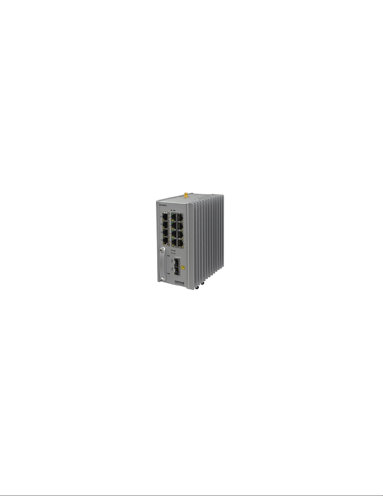
Figure 1 - Illustration of ComNet RLGE2FE16R
Key Features
The Reliance RLGE2FE16R devices offer the following features (subject to configuration options):
» Service aware security of industial control protocols
» Wire speed, non-blocking Layer 2 switching
» Dynamic and static layer 3 routing
» Compact systems with flexible ordering options of interfaces type /quantity
» Advanced Ethernet and IP feature-set
» Integrated Defense-in-Depth tool-set
» Ethernet and Serial interfaces
» Cellular mode
» Fit to harsh industrial environment
» Supported by a dedicated industrial service configuration tool (RLConfig)
TECH SUPPORT: 1.888.678.9427
INS_RLGE2FE16R_REV– 10 Aug 2016 PAGE 16
Page 17

INSTALLATION AND OPERATION MANUAL RLGE2FE16R
Conventions Description
commands CLI and SNMP commands
command example
<Variable> user-defined variables
(numerical variable) numerical variable
{mandatory command parameters} CLI syntax
[Optional Command Parameters] CLI syntax
Seamless & Reliable Connection to Any Network
The RLGE2FE16R provides connectivity to any copper, fiber optic, or cellular radio-based
Ethernet network. Fiber optic networks are supported by the use of two 100/1000FX SFP
uplink ports. The optional highly resilient 2G/3G/4G LTE cellular radio uplink with 2 SIM card
slots for network redundancy, is ideal where fiber optic infrastructure is not available, and may
be used as a back-up link for those applications where interruption of service is not tolerable.
The 8 optional 100 Mbps SFP communications ports provide a simple to implement aggregation
capability to the user’s network.
CLI and SNMP examples
Extremely Effective Network Security
The RLGE2FE16R is available with two different levels of network security software: Standard
Security; or Enhanced Security, for the most mission-critical applications.
Standard Security Software Package Version:
Service Gateway – The RLGE2FE16R service gateway includes a highly robust application layer,
and provides legacy support, an enterprise-class firewall, serial tunnelling, protocol gateway,
and extremely effective encryption technologies. The service gateway offers a uniquely
capable feature set which may serve as the hardware foundation to a secure industrial controls
network, and includes Protocol Gateway, VPN, and IPsec features.
Protocol Gateway – Gateway functionality between a DNP3 TCP client (local) and a DNP3 Serial
RTU, IED, PLC, or other compatible device is supported. This same functionality is supported
across MODBUS TCP to MODBUS RTU, and IEC 61850 101/104 TCP to IEC 61850 101/104 RTU.
This level of protocol conversion allows legacy protocols to be secured by enterprise and
industry best practice level encryption across a TCP IP-based network.
VPN – VPN tunnels are included for secure inter-site connectivity with IPsec, DM-VPN, and VPN
GRE tunnels with key management certificates. The supported VPN modes allow both layer-2
and layer-3 services, to best suit the user’s application-specific cyber-protection needs.
IPSec – Internet Protocol Security (IPsec) is a protocol suite for securing Internet Protocol (IP)
communications by authenticating and/or encrypting each IP packet of a communication
session. IPsec-VPN as well as IPsec encryption are supported over other VPN technologies.
By implementing this level of industry-accepted encryption, data may traverse the network in
a guaranteed delivery method, as well as providing a cohesive and secure methodology for
network communication across legacy and modern networks.
TECH SUPPORT: 1.888.678.9427
INS_RLGE2FE16R_REV– 10 Aug 2016 PAGE 17
Page 18

INSTALLATION AND OPERATION MANUAL RLGE2FE16R
Ease of Installation and Network Integration
High levels of cyber-security experience are not required to successfully deploy the
RLGE2FE16R. It is fully supported by ComNet’s Reliance Product Configuration Utility and
CLI, allowing the secure switch/router to be easily configured, and to diagnose network and
security functions.
Configuration of the secure firewall is also simple. Once connected to the user’s network,
the RLGE2FE16R immediately begins to collect and analyse information across the network,
including from other connected devices, traffic behavior, etc. Recommended firewall rules are
then suggested to the user; the implementation of these rules is optional, and they can be
easily edited using the Configuration Utility.
OAM (IEEE 802.3-2005 & IEEE 802.1ag) and QoS are also supported. Strict priority, Weighted
Round Robin (WRR), ingress policing, and egress traffic shaping are included for traffic
management.
Product Options
Enhanced Security Software Option – Includes all of the security features of the Standard
Security version, plus: Identity management and authentication proxy access (APA), event
logger, IPsec authentication with certificates, cyber-physical Integration, enhanced SCADAaware firewall, and DPI (Deep Packet Inspection) SCADA protocols firewall. This manual does
not cover Enhanced Security Software Options.
Cellular Radio Option – An internal 2G/3G/4G LTE GPRS/UMTS cellular radio modem, with 2
SIM card slots for maximum network reliability and availability. All world-wide cellular radio
frequency bands are supported.
Serial Data Interface Option – The 4-port serial interface is available for applications including
terminal server with protocol gateway and serial tunnelling functionality, and provides direct
connectivity to legacy RS-232 serial data IEDs, RTUs, and other devices.
PoE (Power over Ethernet) Option – 30 watts per port is available for 8 of the RJ-45 Ethernet
communications ports, and is compliant with the IEEE 802.3at specification.
The maximum PoE load per switch is dependant on the voltage type ordered and is shared
across ports 1-8 only. Please refer to the PoE Power Management section for further details.
100 Mbps SFP Option – Includes (8) 100 Mbps SFP ports for network aggregation applications.
Provides (8) 10/100 Mbps copper/RJ-45 communications ports; (8) 100 Mbps SFP ports; and (2)
100/1000 Mbps SFP uplink ports. Note: This option deletes the cellular radio option, as well as
the serial interfaces option.
TECH SUPPORT: 1.888.678.9427
INS_RLGE2FE16R_REV– 10 Aug 2016 PAGE 18
Page 19

INSTALLATION AND OPERATION MANUAL RLGE2FE16R
Hardware and Interfaces
Depending on the RLGE2FE16R hardware variant ordered your switch will hold physical Ethernet
and Serial ports.
» Serial, RJ45 ports, support RS-232. Max 4 ports
» Ethernet RJ45 copper ports are 10/100 FE. Max 16 ports
» Ethernet SFP based ports are 10/100 FE. Max 8 ports.
» Ethernet SFP based ports are 100/1000 GE. Max 2 ports.
Ordering options of Hardware
RLGE2FE16R/S variants do not support the following features:
- APA
- IPSEC X.509
- Event Logger
- Application Aware Firewall
These features are only supported in RLGE2FE16R/E models
RLGE2FE16R Standard Security Models
Part Number Description
RLGE2FE16R/S/XX/28³ RLGE2FE16R with 2 × 100/1000 FX SFP, 8 × 10/100 TX
RLGE2FE16R/S/XX/28/S22³ RLGE2FE16R with 2 × 100/1000 FX SFP, 8 × 10/100 TX, 4 × RS-232
RLGE2FE16R/S/XX/28/CGU³
RLGE2FE16R/S/XX/28/CH+³ RLGE2FE16R with 2 × 100/1000 FX SFP, 8 × 10/100 TX, 2G/3G HSPA+ Cellular Modem
RLGE2FE16R/S/XX/28/CNA³
RLGE2FE16R/S/XX/28/CNA³
RLGE2FE16R/S/XX/28/CEU³ RLGE2FE16R with 2 × 100/1000 FX SFP, 8 × 10/100 TX, 4G LTE Cellular Modem (EU Bands)
RLGE2FE16R/S/XX/28/S22/CGU³
RLGE2FE16R/S/XX/28/S22/CH+³
RLGE2FE16R/S/XX/28/S22/CNA³
RLGE2FE16R/S/XX/28/S22/CEU³
RLGE2FE16R/S/XX/28P³ RLGE2FE16R with 2 × 100/1000 FX SFP, 8 × 10/100 TX PoE+
RLGE2FE16R/S/XX/28P/S22³ RLGE2FE16R with 2 × 100/1000 FX SFP, 8 × 10/100 TX PoE+, 4 × RS-232
RLGE2FE16R/S/XX/28P/CGU³
RLGE2FE16R/S/XX/28P/CH+³ RLGE2FE16R with 2 × 100/1000 FX SFP, 8 × 10/100 TX PoE+, 2G/3G HSPA+ Cellular Modem
RLGE2FE16R with 2 × 100/1000 FX SFP, 8 × 10/100 TX, 2G/3G GPRS/UMTS Cellular
Modem
RLGE2FE16R with 2 × 100/1000 FX SFP, 8 × 10/100 TX, 4G LTE Cellular Modem (NA
Bands)
RLGE2FE16R with 2 × 100/1000 FX SFP, 8 × 10/100 TX, 4G LTE Cellular Modem (NA
Bands)
RLGE2FE16R with 2 × 100/1000 FX SFP, 8 × 10/100 TX, 4 × RS-232, 2G/3G GPRS/UMTS
Cellular Modem
RLGE2FE16R with 2 × 100/1000 FX SFP, 8 × 10/100 TX, 4 × RS-232, 2G/3G HSPA+
Cellular Modem
RLGE2FE16R with 2 × 100/1000 FX SFP, 8 × 10/100 TX, 4 × RS-232, 4G LTE Cellular
Modem (NA Bands)
RLGE2FE16R with 2 × 100/1000 FX SFP, 8 × 10/100 TX, 4 × RS-232, 4G LTE Cellular
Modem (EU Bands)
RLGE2FE16R with 2 × 100/1000 FX SFP, 8 × 10/100 TX PoE+, 2G/3G GPRS/UMTS
Cellular Modem
TECH SUPPORT: 1.888.678.9427
INS_RLGE2FE16R_REV– 10 Aug 2016 PAGE 19
Page 20

INSTALLATION AND OPERATION MANUAL RLGE2FE16R
Part Number Description
RLGE2FE16R/S/XX/28P/CNA³
RLGE2FE16R/S/XX/28P/CEU³
RLGE2FE16R/S/XX/28P/S22/CGU³
RLGE2FE16R/S/XX/28P/S22/CH+³
RLGE2FE16R/S/XX/28P/S22/CNA³
RLGE2FE16R/S/XX/28P/S22/CEU³
RLGE2FE16R /S/ XX /216³ RLGE2FE16R with 2 × 100/1000 FX SFP, 16 × 10/100 TX
RLGE2FE16R /S/ XX /216P ³ RLGE2FE16R with 2 × 100/1000 FX SFP, 8 × 10/100 TX PoE+, 8 × 10/100 TX
RLGE2FE16R/S/XX/288³ RLGE2FE16R with 2 × 100/1000 FX SFP, 8 × 10/100 TX, 8 × 100 FX SFP
RLGE2FE16R/S/XX/288P³ RLGE2FE16R with 2 × 100/1000 FX SFP, 8 × 10/100 TX PoE+, 8 × 100 FX SFP
[3] XX in above part codes is a placeholder for one of the options from the following power input table
RLGE2FE16R with 2 × 100/1000 FX SFP, 8 × 10/100 TX PoE+, 4G LTE Cellular Modem
(NA Bands)
RLGE2FE16R with 2 × 100/1000 FX SFP, 8 × 10/100 TX PoE+, 4G LTE Cellular Modem
(EU Bands)
RLGE2FE16R with 2 × 100/1000 FX SFP, 8 × 10/100 TX PoE+, 4 × RS-232, 2G/3G GPRS/
UMTS Cellular Modem
RLGE2FE16R with 2 × 100/1000 FX SFP, 8 × 10/100 TX PoE+, 4 × RS-232, 2G/3G HSPA+
Cellular Modem
RLGE2FE16R with 2 × 100/1000 FX SFP, 8 × 10/100 TX PoE+, 4 × RS-232, 4G LTE Cellular
Modem (NA Bands)
RLGE2FE16R with 2 × 100/1000 FX SFP, 8 × 10/100 TX PoE+, 4 × RS-232, 4G LTE Cellular
Modem (EU Bands)
Power Input Option Code Description
12 Dual Redundant 9 to 18 VDC Inputs
24 Dual Redundant 18 to 32 VDC Inputs
48 Dual Redundant 36 to 60 VDC Inputs
11 Dual Redundant 85 to 165 VDC Inputs
AC Single 90 to 250 VAC Input
RLGE2FE16R Standard Security Models 220 VDC
Part Number Description
RLGE2FE16R/S/22/28 RLGE2FE16R with 2 × 100/1000 FX SFP, 8 × 10/100 TX, 220 VDC
RLGE2FE16R/S/22/28P RLGE2FE16R with 2 × 100/1000 FX SFP, 8 × 10/100 TX PoE+, 220 VDC
RLGE2FE16R /S/22/216 RLGE2FE16R with 2 × 100/1000 FX SFP, 16 × 10/100 TX, 220 VDC
RLGE2FE16R /S/22/216P RLGE2FE16R with 2 × 100/1000 FX SFP, 8 × 10/100 TX PoE+, 8 × 10/100 TX, 220 VDC
RLGE2FE16R/S/22/288 RLGE2FE16R with 2 × 100/1000 FX SFP, 8 × 10/100 TX, 8 × 100 FX SFP, 220 VDC
RLGE2FE16R/S/22/288P RLGE2FE16R with 2 × 100/1000 FX SFP, 8 × 10/100 TX PoE+, 8 × 100 FX SFP, 220 VDC
RLGE2FE16R Enhanced Security Models
Part Number Description
RLGE2FE16R /E
Replace /S with /E in part code for Enhanced Security software package (refer to the Enhanced
Security Manual)
Options
Optional Part No Description
ANT3G-2M 2G/3G External Grade Cellular Antenna with 2M cable (1 required per switch)
ANT3G-5M 2G/3G External Grade Cellular Antenna with 5M cable (1 required per switch)
ANT4G - 2M 4G LTE External Grade Cellular Antenna with 2M cable (2 required per switch)
TECH SUPPORT: 1.888.678.9427
INS_RLGE2FE16R_REV– 10 Aug 2016 PAGE 20
Page 21

INSTALLATION AND OPERATION MANUAL RLGE2FE16R
Optional Part No Description
ANT4G - 5M 4G LTE External Grade Cellular Antenna with 5M cable (2 required per switch)
Power Supply 12 V, 24 V or 48 VDC DIN Rail power supply
Conformal Coat Add suffix ‘/C’ for Conformally Coated Circuit Boards to extend to condensation conditions
SFP Modules¹ User selection of ComNet SFP (See SFP Modules data sheet for product numbers and compatibility)
DINBKT3 19-inch rack mount panel adapter
If using an RLGE2FE16R unit with cellular modem, please make sure to select the correct configuration
of active USB device for your purposes. Refer to the Cellular modem as a USB device section.
TECH SUPPORT: 1.888.678.9427
INS_RLGE2FE16R_REV– 10 Aug 2016 PAGE 21
Page 22
INSTALLATION AND OPERATION MANUAL RLGE2FE16R
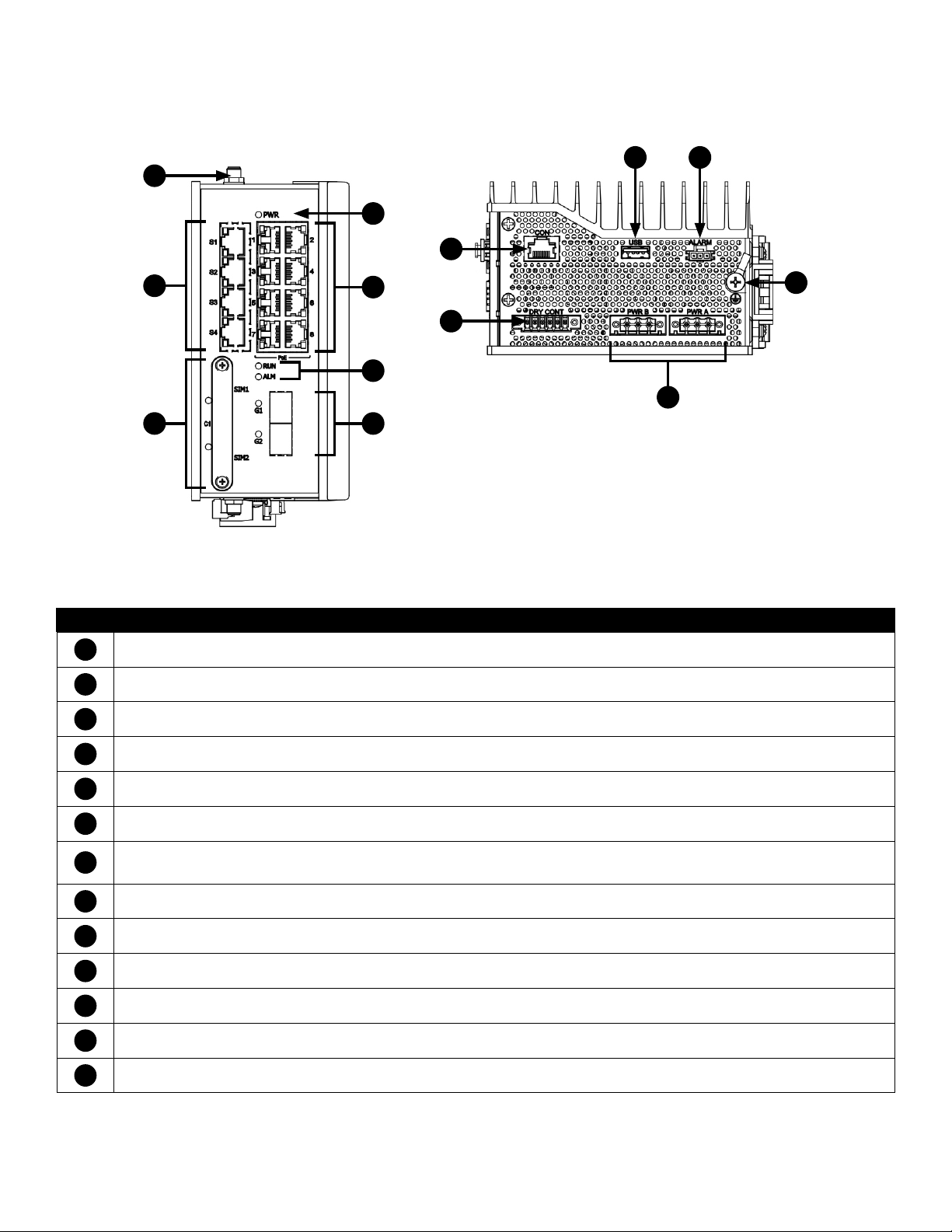
Graphic View of Hardware
10 11
1
4
8
2
5
6
3
7
Figure 2 – R/S/22/28 Variant
Table 1 – RLGE2FE16R Physical Feature Descriptions
Call-out Description
1
Antenna Female Connection
2
RS-232 Ports 1 - 4, Link/Activity (L/A) LED Indicators
3
SIM Card Ports 1 - 2
12
9
13
4
Power LED Indicator
5
10/100 TX Ports 1 - 8 with Optional PoE, Link/Activity (L/A) and Speed LED Indicators
6
RUN and ALM LED Indicators
1000 FX SFP Ports 1- 2 (Fiber Type and Quantity are dependent on installed SFP)
7
SFP Port Link Status and SFP Port Link Speed LED Indicators
8
Console Interface
9
Dry Contact DI/DO Interface
10
USB Interface
11
Alarm Interface
12
Chassis GND Lug
13
Redundant Power Interfaces
TECH SUPPORT: 1.888.678.9427
INS_RLGE2FE16R_REV– 10 Aug 2016 PAGE 22
Page 23

INSTALLATION AND OPERATION MANUAL RLGE2FE16R
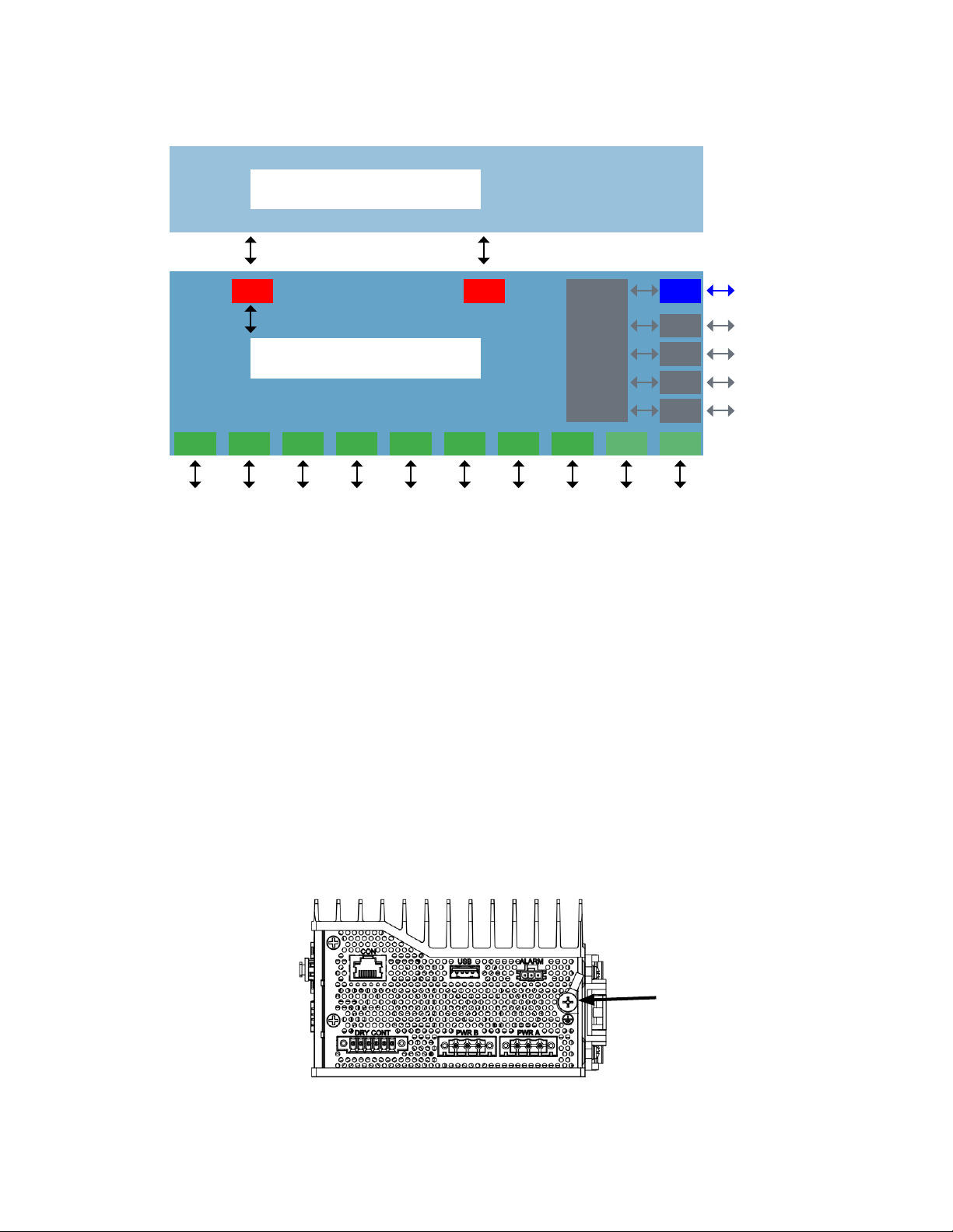
There are several physical varations of this product series dependent on the options selected.
Bottom View
(DC 8TX Model Shown)
DC Models
8TX Ports
DC Models
16TX Ports
DC Models
8TX + 8SFP Port s
AC Models
Side View, All Models
Distance kept for natural air flow
Proper installation depends on natural air flow for cooling. You must maintain a 10cm distance
above and below the ComNet switch for proper air flow.
TECH SUPPORT: 1.888.678.9427
INS_RLGE2FE16R_REV– 10 Aug 2016 PAGE 23
Page 24
INSTALLATION AND OPERATION MANUAL RLGE2FE16R
Logical Structure
Application Router
ACE
Gi 0/4
Switch / Router Packet Processor
GCE
Fa 0/1 Fa 0/2 Fa 0/3 Fa 0/4 Fa 0/5 Fa 0/6 Fa 0/7 Fa 0/8 Gi 0/1
Figure 4 - Logical system view, illustration
Gi 0/3 CEL 2G/3G
232
232
232
232
Serial
Processor
S1
S2
S3
S4
Gi 0/2
Grounding
To install the grounding wire:
» Prepare a minimum 10 American Wire Gauge (AWG) grounding wire terminated by a crimped
two-hole lug. Use a suitable crimping tool to fasten the lug securely to the wire. Adhere to your
company’s policy as to the wire gauge and the number of crimps on the lug.
» Apply some anti-oxidant onto the metal surface.
» Mount the lug on the grounding posts, replace the spring-washers and fasten the bolts. Avoid
using excessive torque.
CAUTION – Do not remove the earth connection unless all power supply connections are
disconnected.
DANGER – Before connecting power to the platform, make sure that the grounding posts are
firmly connected to a reliable ground, as described below.
TECH SUPPORT: 1.888.678.9427
INS_RLGE2FE16R_REV– 10 Aug 2016 PAGE 24
Page 25
INSTALLATION AND OPERATION MANUAL RLGE2FE16R
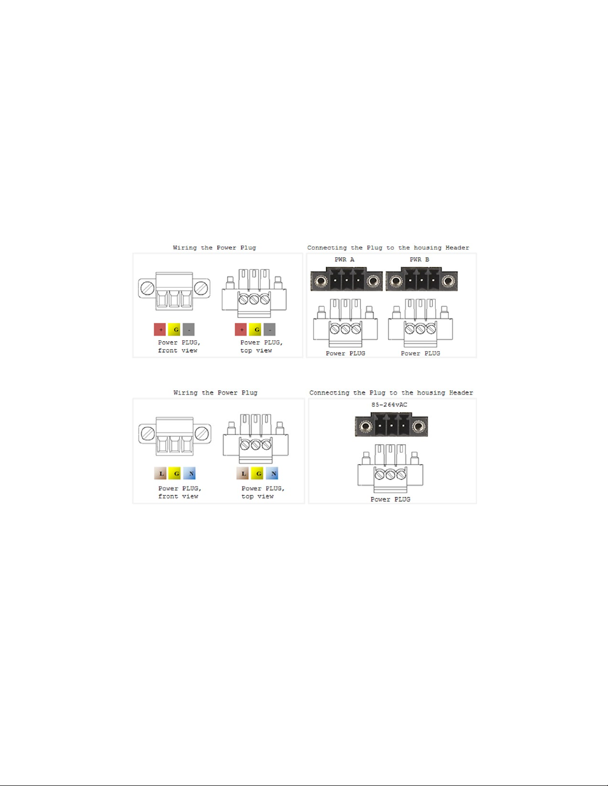
Connecting to a Power Source
Wiring DC Input voltage feed
Input voltage can be either AC or DC depending on the specific module you purchased. Please
take care to notice the label on the back of the module.
For the DC version there are 2 connection inputs, marked as “PWR A” and “PWR B”. For proper
operation it is only necessary to connect one power source, either to “PWR A” or to “PWR B”.
However, for redundancy purposes you may connect 2 different power sources one at “PWR A”
and the second to “PWR B”.
For wiring the voltage an opposite plug connector (2 pcs) is supplied.
Wiring AC Input voltage connector
For an AC product variant there is a single input connector.
Use a Brown wire for the Line (Phase) conductor, a Green/Yellow for the grounding and a Blue wire
for the Neutral conductor. use 18AWG (1mm2) wire, with insulated ferrules.
TECH SUPPORT: 1.888.678.9427
INS_RLGE2FE16R_REV– 10 Aug 2016 PAGE 25
Page 26
INSTALLATION AND OPERATION MANUAL RLGE2FE16R
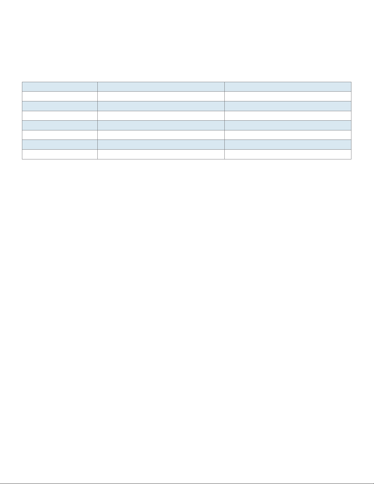
Power Budget
The following table details power consumption of the Hardware variants with cellular and serial
interfaces.
Unit Power feed Max Power [Watt] Version without POE ports Max Power [Watt] Version with POE ports
12vDC 18.5 80
24vDC 18.5 100
48vDC 18.5 140
110 vD C 18.5 120
220vDC 18.5 120
110 vAC 20.35 141
220vAC 20.35 141
Management over Console
Connecting to Device
» Device is capable of being first set up via either the console port, or via an SSH connection
» Default Username and Password
› Username: su
› Password: 1234
» Default all ports act as a flat switch, with all ports as members of VLAN 1
» VLAN 1 set to hold an IP interface by default
» Default Management IP:
› 10.0.0.1/8
TECH SUPPORT: 1.888.678.9427
INS_RLGE2FE16R_REV– 10 Aug 2016 PAGE 26
Page 27
INSTALLATION AND OPERATION MANUAL RLGE2FE16R
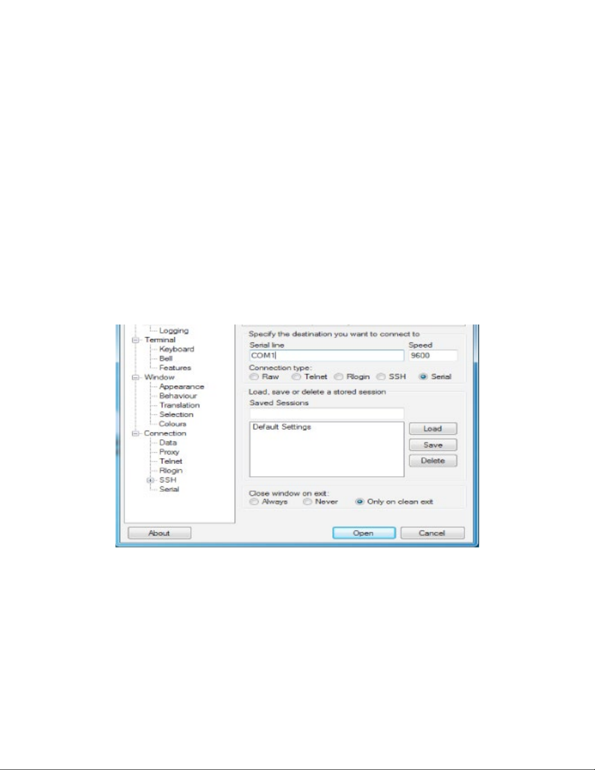
Terminal
» Power on device (Boot may take up to 3 minutes). PWR light should be green
» Console into Device
∙ Connect to CON port using the white ComNet Console Cable. Other console cables will
not work as they have a different pinout.
∙ Connect to to serial port of PC, or use Serial to USB cable. (Drivers may need to be
installed)
∙ Terminal Serial Connection
1. Install and open terminal software
2. Setup terminal for serial session
3. Determine correct COM port on PC (Device manager)
4. Enter correct COM port, enter correct baud rate speed (Default 9600)
5. Click Open to start session with device
∙ Press enter if screen is blank
∙ Default login username su, password 1234 (password will be invisible)
TECH SUPPORT: 1.888.678.9427
INS_RLGE2FE16R_REV– 10 Aug 2016 PAGE 27
Page 28
INSTALLATION AND OPERATION MANUAL RLGE2FE16R
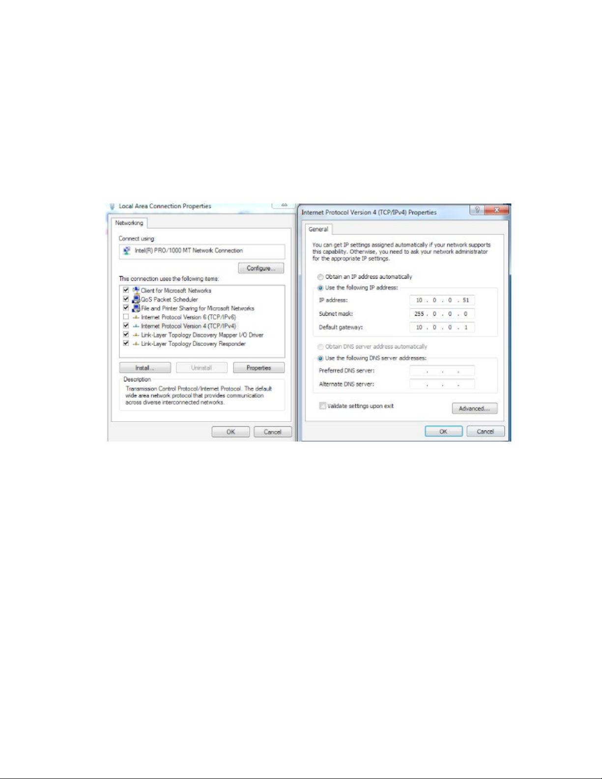
SSH
» SSH Connection to Device
› Setup PC network to be on the same as the default management network
∙ Example PC Setup:
∙ IP Address of PC: 10.0.0.51
∙ Subnet mask: 255.0.0.0
∙ Gateway: 10.0.0.1 (Optional)
» Ping management VLAN IP: 10.0.0.1
» From any terminal session type: ssh su@10.0.0.1
» Default login username su, password 1234 (password will be invisible)
TECH SUPPORT: 1.888.678.9427
INS_RLGE2FE16R_REV– 10 Aug 2016 PAGE 28
Page 29
INSTALLATION AND OPERATION MANUAL RLGE2FE16R
Configuration Environment
Two CLI based configuration environments are available for the user, these are:
» Global Configuration Environment (GCE)
» Application Configuration Environment (ACE)
These two environments are complementing each other and allowing each a set of supported
interfaces, network tools and management. At the RLGE2FE16R infrastructure, the GCE and ACE
are representing two different software processing areas. The physical and logical communication
between these areas are done by internal switching /routing using the Ethernet gigabit ports Gi
0/3 and Gi 0/4. These are known as the ACE ports.
For additional information about the ACE ports see chapter ACE ports.
Command Line Interface
The CLI (Command Line Interface) is used to configure the RLGE2FE16R from a console attached
to the serial port of the switch or from a remote terminal using Telnet or SSH. The following table
lists the CLI environments and modes.
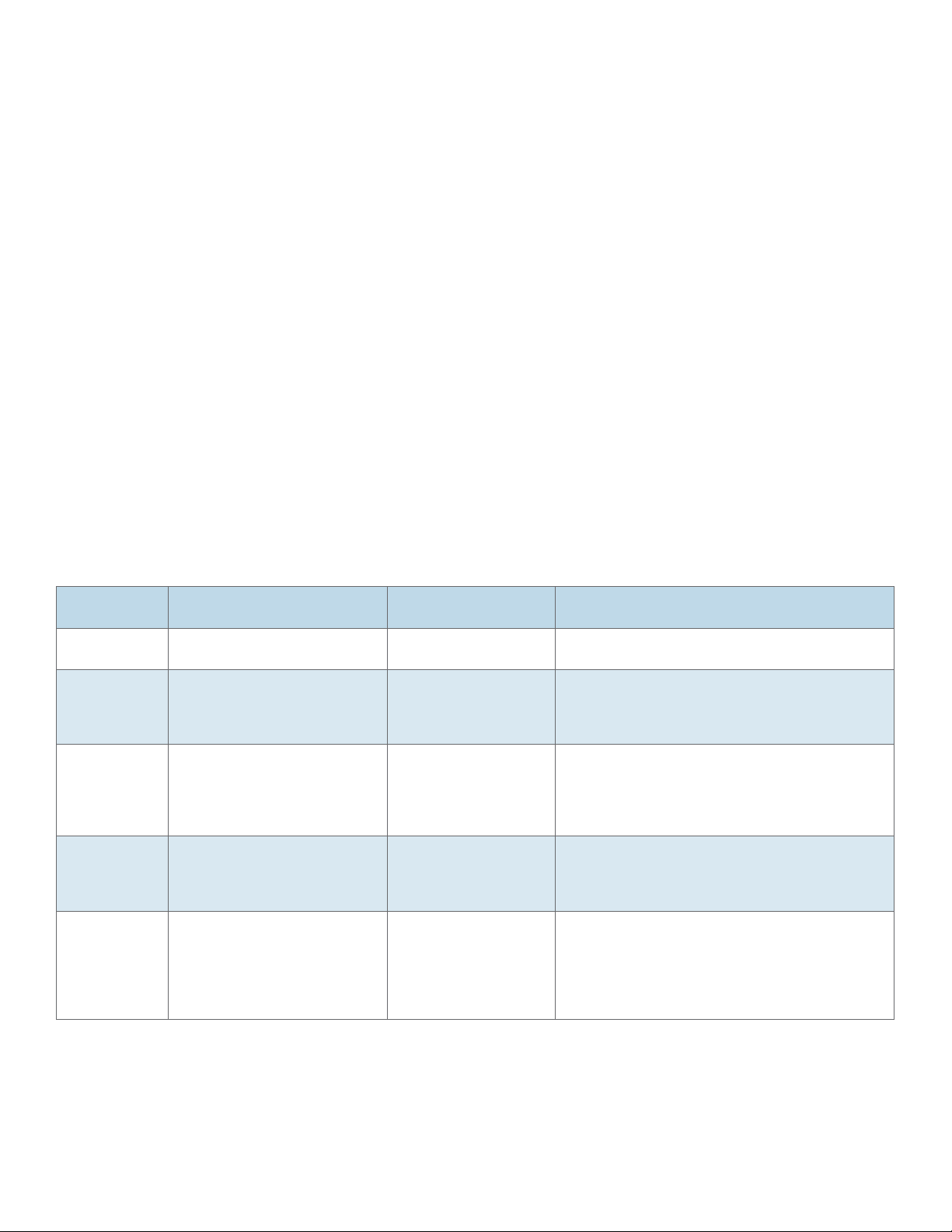
Table 3-1: Command Line Interface
Command
Mode
Root Following user log in this mode
Global
Configuration
Environment
(GCE)
Global
Hierarchy
Configuration
Application
Configuration
Environment
(ACE)
Application
Hierarchy
Configuration
Access Method Prompt Exit Method
is available to the user.
Use the command config to
enter the Global Configuration
mode.
From the Global Configuration
mode command you may drill
down to specific feature sub
tree. Example is shown here for
interface configuration sub tree.
Use the “application connect”
from the Privileged mode
to enter the application
configuration area
From the application root you
may drill down to specific
feature sub tree. example
is shown here for router
configuration sub tree using the
command “router”
RLGE2FE16R # To exit this mode would mean the user to log out
from the system. Use the command logout
RLGE2FE16R(config)# To exit to the Root mode, the commands exit and
end are used.
RLGE2FE16R(config-if)# To exit to the Global Configuration mode, the exit
command is used and to exit to the Root mode,
the end command is used.
[/] To exit to the Global Configuration mode, the exit
command is used
[router/] To exit to the application root use ‘..’ (two dots).
The commands exit and end are not applicable at
this sub tree mode.
TECH SUPPORT: 1.888.678.9427
INS_RLGE2FE16R_REV– 10 Aug 2016 PAGE 29
Page 30

INSTALLATION AND OPERATION MANUAL RLGE2FE16R
Command Line navigation
Minimum Abbreviation
The CLI accepts a minimum number of characters that uniquely identify a command. Therefore,
you can abbreviate commands and parameters as long as they contain enough letters to
differentiate them from any other available commands or parameters on the specific CLI mode.
GREP
The ‘GREP’ and ‘GREP –V’ allows filtering long show outputs.
‘GREP <text>’- filter to output lines which includes the given text.
‘GREP –v <text>’- filter to output lines which do not include the given text.
Example
1. Show running-config vlan without filtering
RLGE2FE16R# show running-config vlan
#Building configuration...
vla n 4091
ports gigabitethernet 0/1-4
!
!
vla n 1
ports fastethernet 0/1-8 gigabitethernet 0/1-4 untagged fastethernet 0/1-8 giga
bitethernet 0/1-2
!
!
vla n 4092
ports gigabitethernet 0/3 fastethernet 0/10-11 untagged fastethernet 0/10-11
!
!
vla n 4093
ports gigabitethernet 0/3
!
!
TECH SUPPORT: 1.888.678.9427
INS_RLGE2FE16R_REV– 10 Aug 2016 PAGE 30
Page 31

INSTALLATION AND OPERATION MANUAL RLGE2FE16R
vlan 10
ports fastethernet 0/1 gigabitethernet 0/3
!
!
mac-address-table static unicast 02:20:d2:fc:1c:78 vlan 4092 interface gigabitet
he r n e t 0/3
mac-address-table static unicast 02:20:d2:fc:1c:79 vlan 4092 interface fastether
net 0/10
mac-address-table static unicast 02:20:d2:fc:1c:7a vlan 4092 interface fastether
net 0/11
2. Show running-config vlan with grep filtering
RLGE2FE16R# show running-config vlan | grep vlan
vla n 4091
vla n 1
vla n 4092
vla n 4093
vlan 10
mac-address-table static unicast 02:20:d2:fc:1c:78 vlan 4092 interface gigabitet…
mac-address-table static unicast 02:20:d2:fc:1c:79 vlan 4092 interface fastether…
mac-address-table static unicast 02:20:d2:fc:1c:7a vlan 4092 interface fastether…
Dynamic Completion of Commands
In addition to the Minimum Abbreviation functionality, the CLI can display the commands’ possible
completions. To display possible command completions, type the partial command followed
immediately by <Tab>.
In case the partial command uniquely identifies a command, the CLI displays the full command.
Otherwise the CLI displays a list of possible completions.
Help (?)
Use ? to retrieve completion options and help for a command.
TECH SUPPORT: 1.888.678.9427
INS_RLGE2FE16R_REV– 10 Aug 2016 PAGE 31
Page 32

INSTALLATION AND OPERATION MANUAL RLGE2FE16R
Keyboard Shortcuts
Following keyboard shortcuts are supported.
1. ‘CTRL D’
a. At the GCE: moves one CLI mode back.
b. At the ACE: exits to GCE Root.
2. ‘CTRL Z’
a. At the GCE: moves to the ROOT.
TECH SUPPORT: 1.888.678.9427
INS_RLGE2FE16R_REV– 10 Aug 2016 PAGE 32
Page 33

INSTALLATION AND OPERATION MANUAL RLGE2FE16R
Supported Functionalities
The RLGE2FE16R is a feature rich industrial unit supporting:
» L2 Ethernet switching
» L3 dynamic and static Routing
» SCADA services
» Firewall
» Secure networking
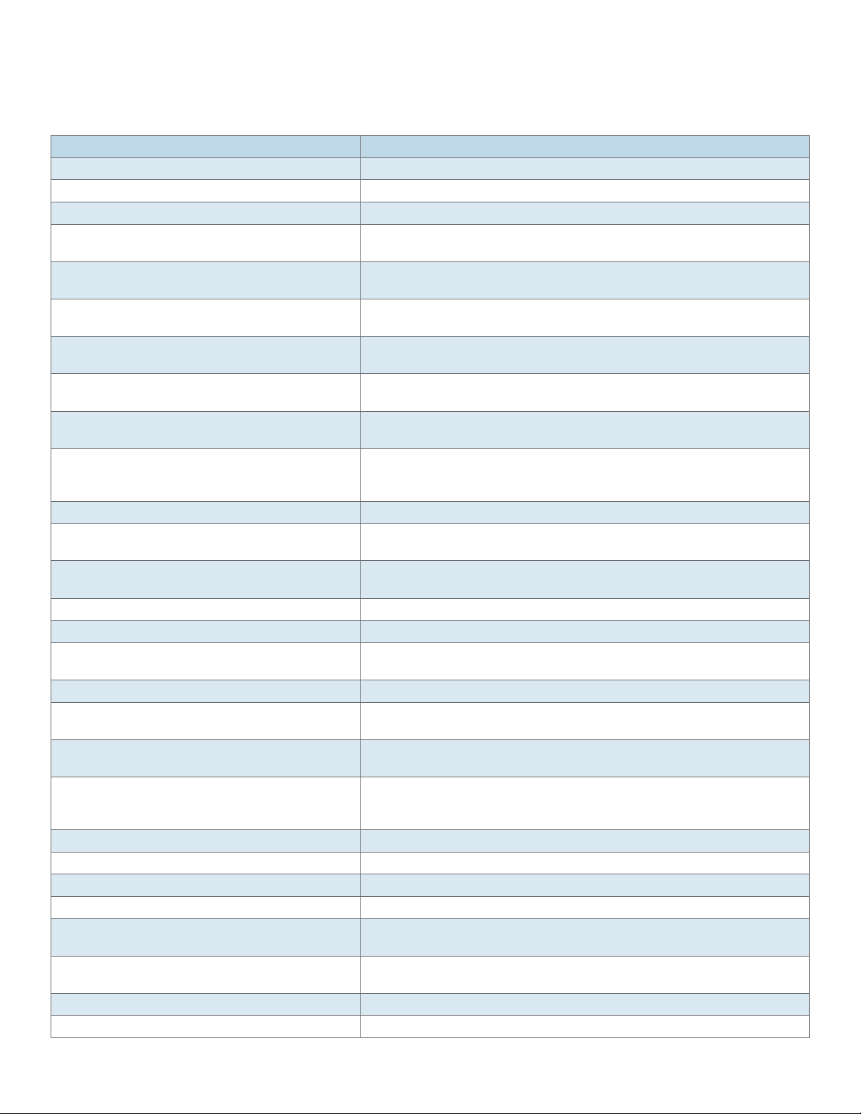
The below table gives a high level view of the supported feature sets and their corresponding
configuration environment.
Global Configuration Environment GCE Application Configuration Environment ACE
L2 Ethernet switching Ethernet ports Serial ports Cellular modem
OSPF Vlan tagging IPSec VPN
Management Authentication SCADA Gateway SCADA Firewall
L2-L4 Firewall QOS Serial services Terminal services
ERP MSTP OSPF RIP
FTP SNMP N AT
The below table details the RLGE2FE16R supported feature and its corresponding configuration
environment.
Group Feature GCE ACE
Interfaces Cellular modem with 2 SIM cards X
FE RJ45 Ports X
Fiber Optic ports X
Gigabit ports X
POE ports X
RS 232 ports ,with control lines X
SFP Ports X
USB X
TECH SUPPORT: 1.888.678.9427
INS_RLGE2FE16R_REV– 10 Aug 2016 PAGE 33
Page 34

INSTALLATION AND OPERATION MANUAL RLGE2FE16R
Group Feature GCE ACE
Switching
Management
Networking LLDP X
Protection Conditioned/ scheduled system reboot X
802.1 X
Auto Crossing X
Auto Negotiation IEEE 802.3ab X
Mac list X
Storm Control X
VLAN segregation Tagging IEEE 802.1q X
IGMP Snooping X
IGMP v1,v2,v3 X
Backup / Restore running config X
Conditioned/ scheduled system reboot X
Console serial port X
FTP client X
Inband Management X
Outband Management X
Remote Upgrade X
Safe Mode X
SFTP Client X
SNMP Trap X
SNMP X
SSH Client X X
Syslog X X
Telnet Client X X
Telnet server X X
TFTP Client X
Web management interface X
OAM CFM ITU-T Y.1731 X
QOS X
ITU-T G.8032v2 Ethernet ring X
Link Aggregation with LACP X
MSTP IEEE 802.1s X
Protection between Cellular ISP (SIM cards backup) X
Spanning Tree X
TECH SUPPORT: 1.888.678.9427
INS_RLGE2FE16R_REV– 10 Aug 2016 PAGE 34
Page 35

INSTALLATION AND OPERATION MANUAL RLGE2FE16R
Group Feature GCE ACE
Routing DHCP Client X
DHCP Relay X
DHCP Server X
IPv4 X X
OSPF v2 X X
RIPv2 X
Static Routing X X
VRRP X
NAT X
Security ACLs , L2-L4 X
Application aware IPS Firewall for SCADA protocols X
IEEE 802.1X Port Based Network Access Control. X
IPSec X
Local Authentication X
MAC limit X
Port shutdown X
RADIUS Accounting and Authentication X
TACACS X
Time Local Time settings X
NTP X
Diagnostics Counters & statistics per Port X
Led diagnostics X
Ping X X
Port mirroring X
Relay Alarm Contact X
RMON X
Trace Route X
Serial Gateway IEC 101/104 gateway X
IEC 104 Firewall X
Serial Transparent Tunneling X
Terminal Server X
VPN L2 GRE VPN X
L3 IPSec VPN X
L3 mGRE DM-VPN X
TECH SUPPORT: 1.888.678.9427
INS_RLGE2FE16R_REV– 10 Aug 2016 PAGE 35
Page 36

INSTALLATION AND OPERATION MANUAL RLGE2FE16R
System Default state
The following table details the default state of features and interfaces.
Feature Default state
Ethernet Ports All ports are enabled
Serial interfaces Disabled
Cellular modem Disabled
Vlan 1 Enabled. All ports are members
Ports PVID All Ethernet ports have pvid 1
POE POE is enabled for supporting hardware
Layer 3 interface Interface vlan 1 is set to : 10.0.0.1/8
Spanning Tree Mst is enabled.
Application ports gigabit 0/3-0/4 are edge ports. Depending on hardware type ports fast 0/90/16 may be edge ports as well (/216 and /288 model variants)
ERP Disabled
LLDP Disabled
SSH Enabled
Telnet Disabled
Http Disabled
Syslog Disabled
Snmp Disabled
Tacacs Disabled
Radius Disabled
ACLs Disabled
SNTP Disabled
Firewall Disabled
VPN Disabled
TECH SUPPORT: 1.888.678.9427
INS_RLGE2FE16R_REV– 10 Aug 2016 PAGE 36
Page 37

INSTALLATION AND OPERATION MANUAL RLGE2FE16R
Root Commands
The Root Configuration Environment list of main CLI commands is shown below
+ root
- help
- clear screen
- enable
- disable
- configure terminal / configure
- run script
- listuser
- lock
- username
- enable password
- line
- access-list provision mode
- access-list commit
- exec-timeout
- logout
- end
- exit
- show privilege
- show line
- show aliases
- show users
- show history
TECH SUPPORT: 1.888.678.9427
INS_RLGE2FE16R_REV– 10 Aug 2016 PAGE 37
Page 38

INSTALLATION AND OPERATION MANUAL RLGE2FE16R
Root Commands Description
Command Description
Help [command] Displays a brief description for the given command.
To display help description for commands with more than one word, do not provide any space
between the words
clear screen Clears all the contents from the screen.
Enable [<0-15> Enable Level] Enters into default level privileged mode.
If required, the user can specify the privilege level by enabling level with a password (login
password) protection to avoid unauthorized user.
Disable [<0-15> Enable Level] Turns off privileged commands. The privilege level varies between 0 and 15. This value should
be lesser than the privilege level value given in the enable command.
configure [terminal] Enters configuration mode.
run script Runs CLI commands from the specified script file.
listuser Lists all the default and newly created users, along with their permissible mode.
Lock Locks the CLI console. It allows the user/system administrator to lock the console to prevent
unauthorized users from gaining access to the CLI command shell. Enter the login password
to release the console lock and access the CLI command shell.
username Creates a user and sets the enable password for that user with the privilege level.
alias - replacement string Replaces the given token by the given string and the no form of the command removes the
alias created for the given string.
access-list commit Triggers provisioning of active filter rules to hardware based on configured priority. This
command is applicable only when provision mode is consolidated. Traffic flow would be
impacted when filter-rules are reprogrammed to hardware.
logout Exits the user from the console session. In case of a telnet session, this command terminates
the session.
end Exits the configuration mode
exit Exits the current config location to one step up in the root
show privilege Shows the current user privilege level
show line Displays TTY line information such as EXEC timeout
show aliases Displays all the aliases
show users Displays the information about the current user.
show history Displays a list of recently executed commands
TECH SUPPORT: 1.888.678.9427
INS_RLGE2FE16R_REV– 10 Aug 2016 PAGE 38
Page 39

INSTALLATION AND OPERATION MANUAL RLGE2FE16R
GCE Commands
The Global Configuration Environment list of main CLI commands is shown below
+ root
+ config terminal
default vlan id
default ip address
ip address
default ip address allocation protocol
ip address - dhcp
login authentication
login authentication-default
authorized-manager ip-source
ip http port
set ip http
archive download-sw
interface-configuration and deletion
mtu frame size
system mtu
loopback local
mac-addr
snmp trap link-status
write
copy
clock set
cli console
flowcontrol
shutdown - physical/VLAN/port-channel/tunnel Interface
debug interface
TECH SUPPORT: 1.888.678.9427
INS_RLGE2FE16R_REV– 10 Aug 2016 PAGE 39
Page 40

INSTALLATION AND OPERATION MANUAL RLGE2FE16R
debug-logging
incremental-save
rollback
shutdown ospf
start ospf
set switch maximum – threshold
set switch temperature – threshold
set switch power – threshold
mac-learn-rate
system contact
system location
clear interfaces – counters
clear counters
show ip interface
show authorized-managers
show interfaces
show interfaces – counters
show system-specific port-id
show interface mtu
show interface bridge port-type
show nvram
show env
show system information
show flow-control
show debug-logging
show debugging
show clock
show running-config
TECH SUPPORT: 1.888.678.9427
INS_RLGE2FE16R_REV– 10 Aug 2016 PAGE 40
Page 41

INSTALLATION AND OPERATION MANUAL RLGE2FE16R
show http server status
show mac-learn-rate
show config log
management vlan-list <port_list>
show iftype protocol deny table
clear line vty
audit-logging logsize-threshold
feature telnet
show telnet server
show audit
set http authentication-scheme
set http redirection enable
http redirect
show http authentication-scheme
show http redirection
TECH SUPPORT: 1.888.678.9427
INS_RLGE2FE16R_REV– 10 Aug 2016 PAGE 41
Page 42
INSTALLATION AND OPERATION MANUAL RLGE2FE16R
GCE Commands Description
Command Description
default mode Configures the mode by which the default interface gets its IP address.
default vlan id
default ip address Configures the IP address and subnet mask for the default interface.
ip address Sets the IP address for an interface. The no form of the command resets
the IP address of the interface to its default value.
default ip address allocation protocol Configures the protocol used by the default interface for acquiring its IP
address.
ip address - dhcp Configures the current VLAN interface to dynamically acquire an IP
address from a DHCP server.
login authentication Configures the authentication method for user logins for accessing the
GUI to manage the switch.
login authentication-default Configures the authentication method for user logins for accessing the
GUI to manage the switch.
authorized-manager ip-source Configures an IP authorized manager and the no form of the command
removes manager from authorized managers list.
ip http port Sets the HTTP port. This port is used to configure the router using the
Web interface. The value ranges between 1 and 65535. The no form of the
command resets the HTTP port to its default value.
set ip http Enables/disables HTTP in the switch.
mtu frame size Configures the maximum transmission unit frame size for all the frames
transmitted and received on all the interfaces in a switch.
snmp trap link-status Enables trap generation on the interface. The no form of this command
disables trap generation on the interface.
clock set Manages the system clock.
Delete startup-cfg Clears the contents of the startup configuration
cli console Enables the console CLI through a serial port. The no form of the
command disables console CLI.
flowcontrol Set the send or receive flow-control value for an interface
[no] shutdown - physical/VLAN/port interface Disables/enables a physical interface / VLAN interface / port-channel
interface
debug interface Sets the debug traces for all the interfaces. The no form of the command
resets the configured debug traces.
debug-logging Configures the displays of debug logs. Debug logs are directed to the
console screen or to a buffer file, which can later be uploaded, based on
the input.
incremental-save Enables/disables the incremental save feature
auto-save trigger Enables / disables the auto save trigger function.
Rollback { enable | disable } Enables/disables the rollback function.
set switch maximum – threshold Sets the switch maximum threshold values of RAM, CPU, and Flash
set switch temperature – threshold Sets the maximum and minimum temperature threshold values of the
switch in Celsius.
mac-learn-rate Configures the maximum number of unicast dynamic MAC (L2) MAC
entries hardware can learn on the system
system contact
system location
TECH SUPPORT: 1.888.678.9427
INS_RLGE2FE16R_REV– 10 Aug 2016 PAGE 42
Page 43

INSTALLATION AND OPERATION MANUAL RLGE2FE16R
Command Description
clear interfaces – counters
clear counters
show ip interface
show authorized-managers
show interfaces
show interfaces – counters
show interface mtu
show interface bridge port-type
show nvram Displays the current information stored in the NVRAM.
show env Displays the status of the all the resources like CPU, Flash and RAM usage,
and also displays the current, power and temperature of the switch.
show system information Displays system information.
show flow-control
show debug-logging
show debugging
show clock
show running-config
show http server status
show mac-learn-rate
port-isolation in_vlan_ID
show port-isolation
audit-logging reset
show config log
memtrace
show memtrace status
management vlan-list <port_list>
show iftype protocol deny table
clear line vty
login block-for
audit-logging logsize-threshold
feature telnet
show telnet server
show audit
set http authentication-scheme
set http redirection enable
http redirect
show http authentication-scheme
show http redirection
audit-logging reset
show config log
clear line vty
tunnel hop-limit
TECH SUPPORT: 1.888.678.9427
INS_RLGE2FE16R_REV– 10 Aug 2016 PAGE 43
Page 44

INSTALLATION AND OPERATION MANUAL RLGE2FE16R
Command Description
tunnel hop-limit
login block-for
audit-logging logsize-threshold
feature telnet
show telnet server
show audit
set http authentication-scheme
set http redirection enable
http redirect
show http authentication-scheme
show http redirection
audit-logging reset
default rm-interface
show config log
show memtrace status
management vlan-list <port_list>
show iftype protocol deny table
clear line vty
audit-logging logsize-threshold
feature telnet
show telnet server
show audit
set http authentication-scheme
set http redirection enable
http redirect
show http authentication-scheme
show http redirection
audit-logging reset
show config log
management vlan-list <port_list>
internal-lan
show iftype protocol deny table
clear line vty
login block-for
audit-logging logsize-threshold
feature telnet
show telnet server
show audit
set http authentication-scheme
set http redirection enable
http redirect
TECH SUPPORT: 1.888.678.9427
INS_RLGE2FE16R_REV– 10 Aug 2016 PAGE 44
Page 45

INSTALLATION AND OPERATION MANUAL RLGE2FE16R
Command Description
show http authentication-scheme
show http redirection
audit-logging reset
show config log
show iftype protocol deny table
clear line vty
login block-for
TECH SUPPORT: 1.888.678.9427
INS_RLGE2FE16R_REV– 10 Aug 2016 PAGE 45
Page 46

INSTALLATION AND OPERATION MANUAL RLGE2FE16R
ACE Commands
The Application Configuration Environment list of main CLI commands is shown below.
+ Application connect
+ Router {interface | route |static |ospf |ip |rip| NAT}
+ cellular { connection | continuous-echo| disable |enable| modem| network| refresh| settings|
show| wan}
+ capture {delete |export |help |show |start |stop}
+ date
+ discrete {service| show}
+ dm-vpn {multipoint-gre| nhrp}
+ dns {host| resolver}
+ exit
+ firewall {log| profile| tcp| serial}
+ idle-timeout
+ iec101-gw {cnt| operation| config iec-101| config iec-104| config gw| show}
+ ipsec {enable| disable| isakmp update| policy| preshared| log-show| show| show-sa proto}
+ ipsec-vpn tunnel {show | create | remove}
+ l2-vpn {fdb| tunnel| nhrp}
+ ping
+ reload {cancel| schedule| show}
+ schedule {add |show |remove}
+ serial {card |port| local-end-point| remote-end-point}
+ ssh
+ ssh-server user {create| remove| show}
+ syslog show
+ telnet
+ terminal-server {admin-status| counters| settings| connections| serial-tunnel| telnet-service}
+ trace
+ version
TECH SUPPORT: 1.888.678.9427
INS_RLGE2FE16R_REV– 10 Aug 2016 PAGE 46
Page 47

INSTALLATION AND OPERATION MANUAL RLGE2FE16R
Main Show Commands
GCE
[System Information]
- os-image show-list
- show system information
- show env all
[Vlan & Ports]
- show vlan
- show running-config interface fastethernet 0/<1-8>
- show running-config interface gigabitethernet 0/<1-2>
- show vlan port config
- show interfaces status
[ACLs]
- show running-config acl
[FDB]
- show mac-address-table
- show ip arp
- show logging
- show interfaces storm-control
[GCE Routing]
- show ip interface
- show ip route
- show ip ospf
- show ip ospf neighbor
- show running-config ospf
- show ip rip database
- show ip rip statistics
- show running-config rip
TECH SUPPORT: 1.888.678.9427
INS_RLGE2FE16R_REV– 10 Aug 2016 PAGE 47
Page 48

INSTALLATION AND OPERATION MANUAL RLGE2FE16R
[SNMP]
- show running-config snmp
[STP]
- show spanning-tree detail
- show spanning-tree summary
[ERP]
- show running-config ecfm
- show ethernet cfm domain
- show ethernet cfm service
- show ethernet cfm maintenance-point local
- show ethernet cfm maintenance-points remote
- show ethernet cfm global information
- show aps ring
- show aps ring global info
ACE
[ACE Routing]
- router interface show
- router route show
- router static
enable
show running-config
show ip route
exit
- router ospf
enable
show running-config
show ip ospf route
TECH SUPPORT: 1.888.678.9427
INS_RLGE2FE16R_REV– 10 Aug 2016 PAGE 48
Page 49

INSTALLATION AND OPERATION MANUAL RLGE2FE16R
show ip ospf neighbor
show ip ospf interface
exit
- router rip
enable
show running-config
show ip rip
exit
[Cellular]
- cellular wan show
- cellular settings show
- cellular network show
- cellular connection show
[VPN & IPSec]
- application connect
- dm-vpn multipoint-gre
- dm-vpn nhrp map
- dm-vpn nhrp map
- dm-vpn nhrp route-show
- l2-vpn tunnel show
- l2-vpn fdb show
- l2-vpn nhrp spoke show
- l2-vpn nhrp hub show
- ipsec-vpn tunnel show
- ipsec show global-defs
- ipsec show preshared
- ipsec show sa
- ipsec show log
TECH SUPPORT: 1.888.678.9427
INS_RLGE2FE16R_REV– 10 Aug 2016 PAGE 49
Page 50

INSTALLATION AND OPERATION MANUAL RLGE2FE16R
[Serial]
- serial card show
- serial port show
- serial local-end-point show
- serial port show slot <4-9> port <1-4>
- serial remote-end-point show
- iec101-gw show all
- terminal-server settings show
- terminal-server connections show
[Firewall]
- show running-config acl
- show access-lists
- firewall log show
- firewall profile show
- firewall tcp show
TECH SUPPORT: 1.888.678.9427
INS_RLGE2FE16R_REV– 10 Aug 2016 PAGE 50
Page 51

INSTALLATION AND OPERATION MANUAL RLGE2FE16R
System Version and Data Base
Configuration Database
By default, User configuration is saved in a file called RLGE2FE16R.conf. Configuration saved
in this file will be available at system startup. If this file is deleted, the system will boot with the
RLGE2FE16Rnvram.txt file holding factory configuration.
User Configuration is taking effect immediately upon entering. No specific COMMIT command is
required.
The user can as well save his running configuration in a file with a chosen name for backup and
boot the system with this file when needed.
Multiple running configuration files can be saved with different names locally on the flash or at an
TFTP /SFTP server.
However, configuration which will not be saved as below example will not be available following
system reboot.
User configuration is saved (to the RLGE2FE16R.conf) using the following command
RLGE2FE16R# write startup-cfg
Building configuration...
[OK]
Removing all user configuration and setting the switch to its factory defaults is done by erasing
the RLGE2FE16R.conf with the following command
RLGE2FE16R# delete startup-cfg
RLGE2FE16R# reload
NOTE – RLGE2FE16R.conf and RLGE2FE16Rnvram.txt files are not accessible for the user to do file
operations on (copy, rename and such)
TECH SUPPORT: 1.888.678.9427
INS_RLGE2FE16R_REV– 10 Aug 2016 PAGE 51
Page 52

INSTALLATION AND OPERATION MANUAL RLGE2FE16R
OS VERSION
Updating of system version is available by TFTP/SFTP server and via the USB port.
Available OS files on the switch can be seen with the command shown below.
Running OS file is marked with “active”.
Upgrading system OS from a USB drive can be done under safe mode interface or under a
running system assuming the USB drive was in place when the system booted.
NOTE – The OS image file is a tar file type. When upgrading the system from the USB the file
should be placed at the root directory of the USB drive. The file should not be unzipped.
NOTE – The USB drive must be FAT32
NOTE – The RLGE2FE16R can hold a maximum of two OS image files. Before downloading a
new OS file to the switch make sure the RLGE2FE16R has on it only one (the active) file. If
needed, delete the unused file before attempting to download the new version.
TECH SUPPORT: 1.888.678.9427
INS_RLGE2FE16R_REV– 10 Aug 2016 PAGE 52
Page 53

INSTALLATION AND OPERATION MANUAL RLGE2FE16R
Running Configuration
The user can save his running configuration to a file with a chosen name for backup and boot the
system with this file when needed.
Multiple running configuration files can be saved with different names locally on the flash or at a
TFTP /SFTP server.
It is also possible to import/export a running configuration file to a USB drive from the safe mode.
Commands Hierarchy
+ Root
- write startup-cfg
- delete startup-cfg
- os-image show-list
- os-image activate flash:<file_name>
- os-image delete flash: <file_name>
- os-image download-sw flash:<file_name>
- os-image download-sw sftp://user:password@aa.bb.cc.dd/file_name
- os-image download-sw tftp://aa.bb.cc.dd/file_name
- startup-config {import | export}
[flash: <file_name> |
sftp://user:password@aa.bb.cc.dd/<file_name> |
tftp://aa.bb.cc.dd/<file_name> ]
- logs-export [flash: <file_name> |
sftp://user:password@aa.bb.cc.dd/<file_name> |
tftp://aa.bb.cc.dd/<file_name> ]
- startup-config show files
- reload
NOTE – System must be rebooted following activation of a new OS image file
TECH SUPPORT: 1.888.678.9427
INS_RLGE2FE16R_REV– 10 Aug 2016 PAGE 53
Page 54

INSTALLATION AND OPERATION MANUAL RLGE2FE16R
Example upgrade the OS from USB
The following flow will demonstrate how to upgrade the OS image file from a USB.
Connect to the switch via console and establish CLI management.
Have a USB stick, formatted to FAT32, holding the OS version at its root directory.
1. Display available OS files
RLGE2FE16R# os-im age show-list
Versions list:
RF _ R LG E 2F E16R _ 3.5.03.11 (ac t iv e)
R F _ R L GE2F E16 R _ 3.1.0 0.25.t ar
2. Deleting unneeded OS files
RLGE2FE16R# os-image delete flash:RF _ 3.1.00.25.tar
RLGE2FE16R# os-im age show-list
Versions list:
RF _ R LG E 2F E16R _ 3.5.03.11 (ac t iv e)
RLGE2FE16R#
3. Downloading OS file from USB
Co m mand sy nta x:
RLGE2FE16R# os-image download-sw flash:<file _ name>
Exa m ple:
R L GE2F E16R# o s -i m a g e d ow n lo ad -s w f l as h:R F _ RL GE2F E16 R _ 3.5.04.15.ta r
RLGE2FE16R# os-im age show-list
Versions list:
RF _ R LG E 2F E16R _ 3.5.03.11 (ac t iv e)
RF _ R LG E 2F E16R _ 3.5.04.15.t a r
RLGE2FE16R#
4. Activating desired OS file (will automatically reboot the device)
R L GE2F E16R# o s -i m a g e a c tiv ate fla s h:RF _ R LG E 2F E16R _ 3.5.04.15.t a r
RLGE2FE16R# os-im age show-list
Versions list:
RF _ R LG E 2F E16R _ 3.5.03.11
RF _ R LG E 2F E16R _ 3.5.04.15.t a r (ac t iv e)
TECH SUPPORT: 1.888.678.9427
INS_RLGE2FE16R_REV– 10 Aug 2016 PAGE 54
Page 55

INSTALLATION AND OPERATION MANUAL RLGE2FE16R
Example upgrade the OS from SFTP
The following flow will show how to upgrade the OS image file from a SFTP server.
1. Display available OS files
RLGE2FE16R# os-im age show-list
Versions list:
RF _ R LG E 2F E16R _ 3.5.03.11 (ac t iv e)
R F _ R L GE2F E16 R _ 3.1.0 0.25.t ar
2. Deleting unneeded OS files
RLGE2FE16R# os-image delete flash:RF _ 3.1.00.25.tar
RLGE2FE16R# os-im age show-list
Versions list:
RF _ R LG E 2F E16R _ 3.5.03.11 (ac t iv e)
RLGE2FE16R#
3. Downloading OS file from sftp
Co m mand sy nta x:
RLGE2FE16R# os-image download-sw sftp://user:password@aa.bb.cc.dd/file _ name
Exa m ple:
RLGE2FE16R# os-image dow nload-sw sftp://user:user@172.17.203.100/RF _ RLGE2FE16R _ 3.5.04.15.tar
----25%-------50%-------75%------100%
RLGE2FE16R# os-im age show-list
Versions list:
RF _ R LG E 2F E16R _ 3.5.03.11 (ac t iv e)
RF _ R LG E 2F E16R _ 3.5.04.15.t a r
RLGE2FE16R#
4. Activating desired OS file (will automatically reboot the device)
R L GE2F E16R# o s -i m a g e a c tiv ate fla s h:RF _ R LG E 2F E16R _ 3.5.04.15.t a r
Switch booting…
RLGE2FE16R# os-im age show-list
Versions list:
RF _ R LG E 2F E16R _ 3.5.03.11
RF _ R LG E 2F E16R _ 3.5.04.15.t a r (ac t iv e)
TECH SUPPORT: 1.888.678.9427
INS_RLGE2FE16R_REV– 10 Aug 2016 PAGE 55
Page 56

INSTALLATION AND OPERATION MANUAL RLGE2FE16R
5. Exporting configuration data base to SFTP server
Co m mand sy nta x:
RLGE2FE16R# startup-config export sftp://user:password@aa.bb.cc.dd/file _ name.
Exa m ple:
RLGE2FE16R# startup-config export sftp://rad:rad@172.18.212.230/config _ january13
Example export db and logs
The following flow will show how to export configuration and logs to a TFTP server
1. Exporting configuration data base to SFTP server
Co m mand sy nta x:
RLGE2FE16R# startup-config export sftp://user:password@aa.bb.cc.dd/file _ name.
Exa m ple:
RLGE2FE16R# startup-config export sftp://rad:rad@172.18.212.230/config _ january13
2. Exporting logs base to SFTP server
Co m mand sy nta x:
RLGE2FE16R# logs-ex port sftp://<user-na me>:<pass-word >@ip-add ress/filena m e
Exa m ple:
RLGE2FE16R# logs-export sftp://rad:rad@172.18.212.230/logs _ january13
Example handling DB files on flash
The following flow will show how to export configuration as a file to the local flash drive
1. Exporting configuration data
RLGE2FE16R# startup-config export flash:db _ march
RLGE2FE16R# startup-config show files
db _ february
db _ test
db _ march
TECH SUPPORT: 1.888.678.9427
INS_RLGE2FE16R_REV– 10 Aug 2016 PAGE 56
Page 57

INSTALLATION AND OPERATION MANUAL RLGE2FE16R
2. Activating DB file from flash
RLGE2FE16R# startup-config import flash: db _ february
startup-config import Successful
Reload to use new db
RLGE2FE16R# reload
Example Import DB from TFTP
The following flow will show how to import configuration from a TFTP server
1. Establish connectivity between the switch and the TFTP server
2. Start importing the target file
RLGE2FE16R# startup-config import tftp://172.18.212.231/RF1 _ ospf.cfg
downloaded size:2408448 Bytes
startup-config import Successful
Reload to use new db
3. Reload the switch for the data base to take effect
RLGE2FE16R# reload
..
..
RF1 login: su
Password:
<129>Mar 10 09:06:28 RF1 CLI Attempt to login as su via console Succeeded
RF1#
TECH SUPPORT: 1.888.678.9427
INS_RLGE2FE16R_REV– 10 Aug 2016 PAGE 57
Page 58

INSTALLATION AND OPERATION MANUAL RLGE2FE16R
Safe Mode
The system has two safe mode menus available. To access safe mode, connect to the switch via
console cable, reboot the unit and interrupt the boot process at the safe mode prompt.
The first Safe mode is used for approved technician only and should not be used unless specified
by ComNet. This safe mode state is available at the prompt
“For first safe mode Press ‘s’...”
The second safe mode is accessible at the following prompt:
##########################
For safe mode Press ‘s’...
##########################
Below screenshot details the 2 safe mode menus and their options for:
1. system reset
2. Load the factory-default configuration for the device
3. Write to EEPROM (should be used only after consulting with ComNet)
4. Recover the device’s images from a package file
5. Export / Import DB (running configuration)
For first safe mode Press ‘s’...
s
Safe mode requested from boot...
-----------------------------------------------------------------------------------------
|safe mode menu:
|
| reset | 1 : Reset the device
|
| format | 2 : Format flash
|
| activate | 3 : Activate sw version on flash
|
| install | 4 : Install first sw version from USB
|
| other | o : write other type field
|
| continue | c : Continue with start up process
|
| help | H : Display help about this utility
|
TECH SUPPORT: 1.888.678.9427
INS_RLGE2FE16R_REV– 10 Aug 2016 PAGE 58
Page 59

INSTALLATION AND OPERATION MANUAL RLGE2FE16R
-----------------------------------------------------------------------------------------c
Extracting software
|s
OK
01/01/70 00:25:34 Running applications
##########################
For safe mode Press ‘s’...
##########################
-----------------------------------------------------------------------------------------
|safe mode menu:
| reset | 1 : Reset the device
| defcfg | 2 : Load the factory-default configuration for the device
| eeprom | 3 : Write to EEPROM
| recover | 4 : Recover the device’s images from a package file
| db | 5 : Export / Import DB
| continue | c : Continue in start up process
| refresh | r : Refresh menu
| help | H : Display help about this utility
-----------------------------------------------------------------------------------------|
SW Image upgrade and Recovery
From the second safe mode, select option 4 “Recover the device’s images from a package file”.
At this sub menu the user can handle system version update ,activatation or restore.
-----------------------------------------------------------------------------------------
|safe mode menu:
| reset | 1 : Reset the device
| defcfg | 2 : Load the factory-default configuration for the device
| eeprom | 3 : Write to EEPROM
| recover | 4 : Recover the device’s images from a package file
| db | 5 : Export / Import DB
| continue | c : Continue in start up process
| refresh | r : Refresh menu
| help | H : Display help about this utility
-----------------------------------------------------------------------------------------
4
#######################################################################
TECH SUPPORT: 1.888.678.9427
INS_RLGE2FE16R_REV– 10 Aug 2016 PAGE 59
Page 60

INSTALLATION AND OPERATION MANUAL RLGE2FE16R
### Device Im age Recovery #########################################
#######################################################################
usb | 1 : Download the package file from USB
ls | 2 : List the available application files
active | 3 : Change the active working application
show | 4 : Display the active working application
remove | 5 : Delete an application
free | 6 : Display the free space in the application file system
main | X : Return to the main menu
help | H : Display help about this menu
Install OS image update from a USB
Follow below steps as an example of uploading a desired OS image stored on a local USB key and
activating it.
1. Access second safe mode, use option 4 “recover” and list the current OS images available at the
switch.
-----------------------------------------------------------------------------------------
|safe mode menu:
| reset | 1 : Reset the device
| defcfg | 2 : Load the factory-default configuration for the device
| eeprom | 3 : Write to EEPROM
| recover | 4 : Recover the device’s images from a package file
| db | 5 : Export / Import DB
| continue | c : Continue in start up process
| refresh | r : Refresh menu
| help | H : Display help about this utility
-----------------------------------------------------------------------------------------
4
#######################################################################
### Device Im age Recovery #########################################
#######################################################################
usb | 1 : Download the package file from USB
ls | 2 : List the available application files
active | 3 : Change the active working application
show | 4 : Display the active working application
remove | 5 : Delete an application
free | 6 : Display the free space in the application file system
TECH SUPPORT: 1.888.678.9427
INS_RLGE2FE16R_REV– 10 Aug 2016 PAGE 60
Page 61

INSTALLATION AND OPERATION MANUAL RLGE2FE16R
main | X : Return to the main menu
help | H : Display help about this menu
2
List of sw versions:
3.5.04.32 (ac t iv e)
3.5.04.15
2. Delete the unused OS-Image file
-----------------------------------------------------------------------------------------
|safe mode menu:
| reset | 1 : Reset the device
| defcfg | 2 : Load the factory-default configuration for the device
| eeprom | 3 : Write to EEPROM
| recover | 4 : Recover the device’s images from a package file
| db | 5 : Export / Import DB
| continue | c : Continue in start up process
| refresh | r : Refresh menu
| help | H : Display help about this utility
-----------------------------------------------------------------------------------------
4
#######################################################################
### Device Im age Recovery #########################################
#######################################################################
usb | 1 : Download the package file from USB
ls | 2 : List the available application files
active | 3 : Change the active working application
show | 4 : Display the active working application
remove | 5 : Delete an application
free | 6 : Display the free space in the application file system
main | X : Return to the main menu
help | H : Display help about this menu
5
List of sw versions:
3.5.04.32 (ac t iv e)
3.5.04.15
Enter version name
TECH SUPPORT: 1.888.678.9427
INS_RLGE2FE16R_REV– 10 Aug 2016 PAGE 61
Page 62

INSTALLATION AND OPERATION MANUAL RLGE2FE16R
For main menu press X
3.5.04.15
Removing version 3.5.04.15
Version was deleted successfully
3. Download a new OS Image file from the usb. A list of available files at the usb will be displayed.
Copy the complete file name and path. Below examples relates to version 4.0.02.10.tar
-----------------------------------------------------------------------------------------
|safe mode menu:
| reset | 1 : Reset the device
| defcfg | 2 : Load the factory-default configuration for the device
| eeprom | 3 : Write to EEPROM
| recover | 4 : Recover the device’s images from a package file
| db | 5 : Export / Import DB
| continue | c : Continue in start up process
| refresh | r : Refresh menu
| help | H : Display help about this utility
-----------------------------------------------------------------------------------------
4
#######################################################################
### Device Im age Recovery #########################################
#######################################################################
usb | 1 : Download the package file from USB
ls | 2 : List the available application files
active | 3 : Change the active working application
show | 4 : Display the active working application
remove | 5 : Delete an application
free | 6 : Display the free space in the application file system
main | X : Return to the main menu
help | H : Display help about this menu
1
-rw-rw-rw- 1 root root 58112000 Jan 21 2014 /mnt/usb/RF _ RLGE2FE16R _ 3.5.04.15.
tar
-rw-rw-rw- 1 root root 59494400 Apr 7 2014 /mnt/usb/RF _ RLGE2FE16R _ 3.5.04.31.
tar
-rw-rw-rw- 1 root root 59555840 Jun 5 2014 /mnt/usb/RF _ RLGE2FE16R _ 3.6.04.24.
tar
-rw-rw-rw- 1 root root 59842560 Jun 2 2014 /mnt/usb/RF _ RLGE2FE16R _ 4.0.02.10.
tar
Enter version number on usb.
TECH SUPPORT: 1.888.678.9427
INS_RLGE2FE16R_REV– 10 Aug 2016 PAGE 62
Page 63

INSTALLATION AND OPERATION MANUAL RLGE2FE16R
For main menu press X
/m nt/u s b/R F _ R L G E 2F E16R _ 4.0.02.10.t a r
Version was installed successfully
4. Activate the new version. The system will boot
-----------------------------------------------------------------------------------------
|safe mode menu:
| reset | 1 : Reset the device
| defcfg | 2 : Load the factory-default configuration for the device
| eeprom | 3 : Write to EEPROM
| recover | 4 : Recover the device’s images from a package file
| db | 5 : Export / Import DB
| continue | c : Continue in start up process
| refresh | r : Refresh menu
| help | H : Display help about this utility
-----------------------------------------------------------------------------------------
4
#######################################################################
### Device Im age Recovery #########################################
#######################################################################
usb | 1 : Download the package file from USB
ls | 2 : List the available application files
active | 3 : Change the active working application
show | 4 : Display the active working application
remove | 5 : Delete an application
free | 6 : Display the free space in the application file system
main | X : Return to the main menu
help | H : Display help about this menu
3
List of sw versions:
3.5.04.32 (ac t iv e)
4.0.02.10
Enter version to activate
For main menu press X
4.0.02.10
Updating bank1 with vmlinux.UBoot file, please wait ...
TECH SUPPORT: 1.888.678.9427
INS_RLGE2FE16R_REV– 10 Aug 2016 PAGE 63
Page 64

INSTALLATION AND OPERATION MANUAL RLGE2FE16R
Installing First OS image from a USB
Follow below steps as an example of installing a first version from a usb. Local database and any
active OS image will be deleted. The system will boot with manufacturing defaults using the new
OS imported file.
1. Access first safe mode, use option 4 “install”. Select the version to be used. the system will boot
automatically to activate the new OS.
-----------------------------------------------------------------------------------------
Safe mode requested from boot...
-----------------------------------------------------------------------------------------
|safe mode menu:
|
| reset | 1 : Reset the device
|
| format | 2 : Format flash
|
| activate | 3 : Activate sw version on flash
|
| install | 4 : Install first sw version from USB
|
| other | o : write other type field
|
| continue | c : Continue with start up process
|
| help | H : Display help about this utility
|
-----------------------------------------------------------------------------------------
4
!!!!!!!!!!!!!!!!!!!!!!!!!!!!!!!!!!!!!!!!!!!!!!!!!!!!!!!!!!!!!!!!!!!!!!!!!!!!!!!!!!!!!!!!!!!!!!!!
!!!!!!!!!!!!!!!!!!!!!!!!! T h i s c h o i c e w i l l d e l e t e d a t a f r o m f l a s h !!!!!!!!!!!!!!!!!!!!!!!!!!!!!!
!!!!!!!!!!!!!!!!!!!!!!!!! C o n t i n u e [ y /n] !!!!!!!!!!!!!!!!!!!!!!!!!!!!!!
!!!!!!!!!!!!!!!!!!!!!!!!!!!!!!!!!!!!!!!!!!!!!!!!!!!!!!!!!!!!!!!!!!!!!!!!!!!!!!!!!!!!!!!!!!!!!!!!
y
-rw-rw-rw- 1 root root 58112000 Jan 21 2014 /mnt/usb/RF _ RLGE2FE16R _ 3.5.04.15.
tar
-rw-rw-rw- 1 root root 59842560 Jun 2 2014 /mnt/usb/RF _ RLGE2FE16R _ 4.0.02.10.
tar
Enter version number on usb.
For main menu press X
/m n t /u s b/R F _ R L GE2F E16R _ 3.5.04.15.ta r
TECH SUPPORT: 1.888.678.9427
INS_RLGE2FE16R_REV– 10 Aug 2016 PAGE 64
Page 65

INSTALLATION AND OPERATION MANUAL RLGE2FE16R
Veryfing sw version RF _ RLGE2FE16R _ 3.5.04.15.tar
bcm _ sdk _ iss _ app.tar.gz: OK
SW version was verified successfuly
vmlinux.tar
vmlinux.UBoot: OK
Updating bank1 with vmlinux.UBoot file, please wait ...OK
System Database Import/ Export
To import/ export system configuration database, access the second safe mode.
1. Access second safe mode, use option 4 “recover” and list the current OS images available at the
switch.
-----------------------------------------------------------------------------------------
|safe mode menu:
| reset | 1 : Reset the device
| defcfg | 2 : Load the factory-default configuration for the device
| eeprom | 3 : Write to EEPROM
| recover | 4 : Recover the device’s images from a package file
| db | 5 : Export / Import DB
| continue | c : Continue in start up process
| refresh | r : Refresh menu
| help | H : Display help about this utility
-----------------------------------------------------------------------------------------
4
-----------------------------------------------------------------------------------------
|safe mode menu:
| reset | 1 : Reset the device
| defcfg | 2 : Load the factory-default configuration for the device
| eeprom | 3 : Write to EEPROM
| recover | 4 : Recover the device’s images from a package file
| db | 5 : Export / Import DB
| continue | c : Continue in start up process
| refresh | r : Refresh menu
| help | H : Display help about this utility
-----------------------------------------------------------------------------------------
TECH SUPPORT: 1.888.678.9427
INS_RLGE2FE16R_REV– 10 Aug 2016 PAGE 65
Page 66

INSTALLATION AND OPERATION MANUAL RLGE2FE16R
2. At the sub menu, select option 5 “db”. Use option 3 to view available db files at the usb (for
import). Below example demonstrate importing a db file named “ss_spoke1” from the usb and
booting the system with it.
3
List of db files on usb:
-rwxr-xr-x 1 root root 2503168 Jan 1 1980 ss _ spoke1
-----------------------------------------------------------------------------------------
|safe mode menu:
| reset | 1 : Reset the device
| defcfg | 2 : Load the factory-default configuration for the device
| eeprom | 3 : Write to EEPROM
| recover | 4 : Recover the device’s images from a package file
| db | 5 : Export / Import DB
| continue | c : Continue in start up process
| help | H : Display help about this utility
5
#########################################################
### Export / Import DB ###############################
#########################################################
export | 1 : Export DB to usb
import | 2 : Import DB from usb
list | 3 : Show list of db files on usb
main | X : Return to the main menu
help | H : Display help about this menu
2
Import Db from usb
Enter file name
ss_spoke1
-----------------------------------------------------------------------------------------
|safe mode menu:
| reset | 1 : Reset the device
| defcfg | 2 : Load the factory-default configuration for the device
| eeprom | 3 : Write to EEPROM
| recover | 4 : Recover the device’s images from a package file
| db | 5 : Export / Import DB
| continue | c : Continue in start up process
TECH SUPPORT: 1.888.678.9427
INS_RLGE2FE16R_REV– 10 Aug 2016 PAGE 66
Page 67

INSTALLATION AND OPERATION MANUAL RLGE2FE16R
| help | H : Display help about this utility
-----------------------------------------------------------------------------------------
C
…….
TECH SUPPORT: 1.888.678.9427
INS_RLGE2FE16R_REV– 10 Aug 2016 PAGE 67
Page 68

INSTALLATION AND OPERATION MANUAL RLGE2FE16R
Port Interfaces
Port addressing
The ports are configured as <interface-type> <port id>
Command Description
interface-type <> Specify the interface type
Fastethernet
gigabitethernet
Port id <> Specify the port id in a slot number/port format
Slot number is: 0 for Ethernet ports, 1 for Serial ports
Port number is in the range of 0-16 (depending on hardware configuration)
A Logical View Of Ports
Below screenshots show available typical ports of a RLGE2FE16R with 8 Ethernet ports.
RLGE2FE16R# show vlan
Switch defau lt
Vlan database
---------------
Vlan ID : 1
Member Ports : Fa0/1, Fa0/2, Fa0/3, Fa0/4, Fa0/5, Fa0/6
Fa0/7, F a 0/8, G i0/1, Gi0/2, Gi0/3, G i0/4
Untagged Ports : Fa0/1, Fa0/2, Fa0/3, Fa0/4, Fa0/5, Fa0/6
Fa0/7, F a 0/8, G i0/1, Gi0/2
Forbidden Ports : None
Name :
Status : Permanent
----------------------------------------------------
Vlan ID : 4092
Member Ports : Gi0/3, Fa0/10, Fa0/11
Untagged Ports : Fa0/10, Fa0/11
Forbidden Ports : None
Name :
Status : Permanent
----------------------------------------------------
NOTE – The RS232 ports are configured and identified within the ACE CLI mode and are not
seen at “show vlan”. See chapter Serial Interfaces for more information.
TECH SUPPORT: 1.888.678.9427
INS_RLGE2FE16R_REV– 10 Aug 2016 PAGE 68
Page 69

INSTALLATION AND OPERATION MANUAL RLGE2FE16R
NOTE – The RLGE2FE16R has several hardware ordering options of interfaces. The Ethernet
interfaces which are applicable to the hardware will be available for configuration.
Enabling Ports
In order to be accessible, the required interfaces must be activated. This is done using the no
shutdown command.
1. Example of enabling port interface number 5
RLGE2FE16R(config)# interface fastethernet 0/5
RLGE2FE16R(config-if)# no shutdown
RLGE2FE16R(config-if)# end
RLGE2FE16R# write startup-cfg
NOTE – System Default has all ports as enabled
The show interfaces command displays the complete information of all available interfaces.
ACE Ports
Ports Gigabitethernet 0/3 and Gi 0/4 are unique ports. These are internal system ports used for
directing access and network traffic handled at the GCE to the Application services.
The use of these ports should be made in accordance to configuration instructions given in
relevant chapters of this manual.
Default state
Vlan id / port Gi 0/3 Gi 0/4
Vlan 4092 Tagged
Vlan 4093 Tagged
Vlan 1 Tagged (pvid) Tagged
NOTE – The ACE ports properties should not be changed from their default settings of auto-
negotiation and hybrid state.
TECH SUPPORT: 1.888.678.9427
INS_RLGE2FE16R_REV– 10 Aug 2016 PAGE 69
Page 70

INSTALLATION AND OPERATION MANUAL RLGE2FE16R
Vlan assignment
The assignment of the ACE ports to a VLAN is always as a tagged member.
Following table summarizes the ports VLAN membership depending on the network planning.
Networking / port Gi 0/3 Gi 0/4
Serial tunneling Service VLANs
Terminal Server Service VLANs
Gateway Service VLANs
L2 VPN NNI Vlan UNI Vlan
L3 VPN NNI Vlan
IPsec NNI Vlan
Cellular
Firewall Service VLANs
Ports FE 0/9-0/16
The usage of ports FE 0/9 - 0/16 is dependent on the hardware type.
With hardware versions of /216 and /288 these ports are standard user ports to be addressed and
configured for all application purposes.
With hardware versions of /28 these ports are not physically available for the user but are still
mapped in the CLI. At this case these ports are designated for internal system functions and
should not be addressed by the user unless specifically mentioned in a configuration setup of
feature in this manual.
NOTE – With hardware versions of /28 these ports properties should not be changed from their
default settings of auto-negotiation and hybrid state.
TECH SUPPORT: 1.888.678.9427
INS_RLGE2FE16R_REV– 10 Aug 2016 PAGE 70
Page 71

INSTALLATION AND OPERATION MANUAL RLGE2FE16R
POE Ports
Depending on your hardware variant POE ports might be applicable.
PoE is supported at the RJ-45 ports only.
Hardware supporting POE is named:
RLGE2FE16R/X/XX/28P, RLGE2FE16R/X/XX/216P and RLGE2FE16R/X/XX/288P - hardware
includes 8 POE support on the FE Ethernet ports 1-8. All POE ports are wired as Alternative-A
(PoE runs on the FE twisted pairs). Each port supports up to 30w PoE. Notice the total PoE power
allowed per the unit and per port group.
PoE2
RLGE2FE16R
8xPOE
P1
P2
P3
P4
P5
P6
P7
P8
P9
P10
TECH SUPPORT: 1.888.678.9427
INS_RLGE2FE16R_REV– 10 Aug 2016 PAGE 71
Page 72

INSTALLATION AND OPERATION MANUAL RLGE2FE16R
Power Management of POE
1. The 8 POE ports supports in total maximum power output of:
a. For 12Vdc powered units (RLGE2FE16R/X/12) : 60 W
b. For 24Vdc powered units (RLGE2FE16R/X/24) : 80 W
c. For 48Vdc powered units (RLGE2FE16R/X/48) : 120 W
d. For 110Vdc powered units (RLGE2FE16R/X/11) : 100 W
e. For 220Vdc powered units (RLGE2FE16R/X/22) : 100 W
f. For AC powered units (RLGE2FE16R/X/AC) : 120 W
2. The 8 POE ports divided to 2 groups , each group supports maximum power output of:
1. For 12Vdc powered units (RLGE2FE16R/X/12) : 30 W
2. For 24Vdc powered units (RLGE2FE16R/X/24) : 40 W
3. For 48Vdc powered units (RLGE2FE16R/X/48) : 60 W
4. For 110Vdc powered units (RLGE2FE16R/X/11) : 50 W
5. For 220Vdc powered units (RLGE2FE16R/X/22) : 50 W
6. For AC powered units (RLGE2FE16R/X/AC) : 60 W
7. The group division is as follows:
a. Group 1: p1,p2,p3,p6
b. Group 2: p4,p5,p7,p8
Mode of PoE
All PoE models are provided with “Alternative A” wired ports and will supply POE power by IEEE
802.3at negotiation on demand. Non-POE equipment connected to such port is protected as it
will not receive power over the Fast Ethernet communication lines.
TECH SUPPORT: 1.888.678.9427
INS_RLGE2FE16R_REV– 10 Aug 2016 PAGE 72
Page 73

INSTALLATION AND OPERATION MANUAL RLGE2FE16R
POE command Hierarchy
+ Root
+ config terminal
+ interface <type> <port id>
- poe-power { detect | manual }
- poe { shutdown | no shutdown }
- show poe-status port <1-8>
POE Commands Description
Command Description
Config terminal
Interface <type> <port id> Enter the specific Interface.
only fastethernet ports are applicable.
Permissible values : Fastethernet <1-8>
Poe No shutdown: port is POE enabled.
Shutdown: port is POE disabled. (default)
poe-power Detect: POE will be available only upon negotiation with a POE connected load device.
(default)
Manual: POE will be available constantly.
Caution: connect only POE capable load devices to por ts which are in Manual mode.
show poe-status port <> Show the POE state of the port.
Port number is in the range 1-8, relating to fastethernet 1-8.
TECH SUPPORT: 1.888.678.9427
INS_RLGE2FE16R_REV– 10 Aug 2016 PAGE 73
Page 74

INSTALLATION AND OPERATION MANUAL RLGE2FE16R
Controlling Ports
Storm Control
Sets the storm control rate for broadcast, multicast
Rate Limit Output
Enables the rate limiting and burst size rate limiting by configuring the egress packet rate of an
interface and the no form of the command disables the rate limiting and burst size rate limiting on
an egress port
Ports command Hierarchy
+ Root
+ config terminal
+ interface [range] <type> {<port id>| <iface_list>}
- [no] alias DESCRIPTION
- [no] speed (10 | 100 | 1000 | auto)
- [no] duplex (auto | full | half)
- [no] switchport pvid <vlan ID>
- [no] switchport mode {access | trunk | hybrid}
- [no] switchport acceptable-frame-type {all | tagged | untaggedAndPrioritytagged}
- [no] system-specific port-id <id>
- [no] snmp trap link-status
- [no] negotiation
- flowcontrol (receive | send) (desired | on | off)
- mtu <mtu-value>
- [no] shutdown
- [no] storm-control { broadcast |multicast | dlf } level <pps (1-250,000>
- [no] rate-limit output [rate-limit] [burst-limit]
TECH SUPPORT: 1.888.678.9427
INS_RLGE2FE16R_REV– 10 Aug 2016 PAGE 74
Page 75
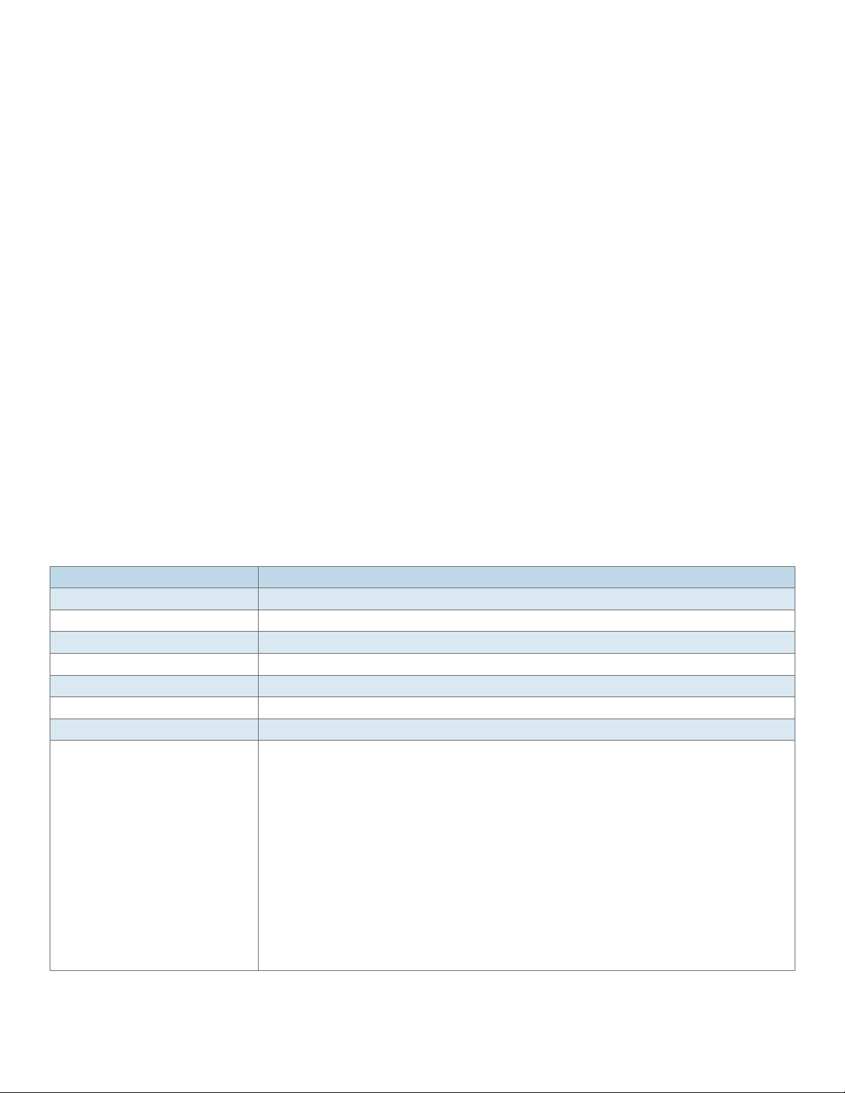
INSTALLATION AND OPERATION MANUAL RLGE2FE16R
- switchport unicast-mac learning limit <limit value(0-32767)>
- switchport unicast-mac learning { enable | disable }
clear interfaces [ <interface-type> <interface-id> ] counters
clear counters [ <interface-type> <interface-id> ]
- Show interfaces [<interface-type> <interface-id>] [vlan <vlan-id> ]
- Show interfaces <type> <port id>
- show interface mtu
- show interfaces status
- show interfaces counters
- show interfaces capabilities
- show vlan port config [port <type> <port id>]
- show running-config interface <type> <port id>
Port Commands Description
Command Description
Config terminal
Interface <type> <port id>
Alias Set a description name for the port.
Speed Set manual speed to the port. Requires first disabling ‘negotiation’ at the port.
Default: negotiation enabled.
Duplex Set port duplex as full | half | auto.
Default: full
switchport mode Configures the mode of operation for a switch port. This mode defines the way of handling
of traffic for VLANs.
Access: accepts and sends only untagged. This kind of port is added as a member to
specific VLAN only and carries traffic only for the VLAN to which the port is assigned.
This mode is allowed only if the port is not a tagged member at any vlan.
The port property of “switchport acceptable-frame-type” must be set to untagged AND
priority Tagged”.
Trunk: accepts and sends only tagged frames. This kind of port is added as member of all
existing VLANs and for any new VLAN created, and carries traffic for all VLANs. The trunk
port accepts untagged frames too, if the “switchport acceptable-frame-type” is set as “all”.
The port can be set as trunk por t, only if the port is not a member of untagged ports for
any VLAN in the switch.
Hybrid: Configures the port as hybrid port that accepts and sends both tagged and
untagged frames.
Default: Hybrid
TECH SUPPORT: 1.888.678.9427
INS_RLGE2FE16R_REV– 10 Aug 2016 PAGE 75
Page 76

INSTALLATION AND OPERATION MANUAL RLGE2FE16R
Command Description
switchport pvid The PVID represents the VLAN ID that is to be assigned to untagged frames.
The packets are processed against PVID, if the packets accepted at ingress is not having a
tag.
Permissible range: 1-4000.
default: 1.
switchport acceptable frame-type
negotiation Enables port auto negotiation of speed.
default: enabled
mtu frame size This command configures the maximum transmission unit frame size for all the frames
transmitted and received on all the interfaces in a switch. The size of the MTU frame size
can be increased using this command. The value ranges between 90 and 9216.
This value defines the largest PDU that can be passed by the interface without any need for
fragmentation. This value is shown to the higher interface sub-layer and should not include
size of the encapsulation or header added by the interface. This value represents the IP
MTU over the interface, if IP is operating over the interface.
Note: Any messages larger than the MTU are divided into smaller packets before
transmission
Default : 1500
system-specific port-id <> This command configures the system specific index for the port. It provides a different
numbering space other than the IfIndex to identify ports. The value ranges between 1 and
163 8 4.
Default : 0.
[no] snmp trap link-status This command enables trap generation on the interface. The no form of this command
disables trap generation on the interface.
The interface generated linkUp or linkDown trap. The linkUp trap denotes that the
communication link is available and ready for traffic flow. The linkDown trap denotes that
the communication link failed and isnot ready for traffic flow.
Default : enable
flowcontrol
{ send | receive} Send : Sets the interface to send flow control packets to a remote device
Receive : Sets the interface to receive flow control packets from a remote device
{ on | off |desired} On : If used with receive allows an interface to operate with the attached device to send
flow control packets .If used with send the interface sends flowcontrol packets to a remote
device if the device supports it
Off : Turns-off the attached devices (when used with receive) or the local ports (when
used with send) ability to send flow-control packets to an interface or to a remote device
respectively
Desired : Allows a local port to operate with an attached device that is required to send
flow control packets or that may send the control packets, when used with receive option.
Allows the local port to send administrative status to a remote device if the remote device
supports it, when used with send option.
storm-control sets the storm control rate for broadcast, multicast and DLF packets
broadcast - Broadcast packets
multicast - Multicast packets
dlf - Unicast packets
level - Storm-control suppression level as a total number of packets per second.
Permissible values : 1-250,000
rate-limit output rate-value - Line rate in kbps
burst-value- Burst size value in kbps
clear interfaces [ <interface-type>
<interface-id> ] counters
clears all the current interface counters from the interface
TECH SUPPORT: 1.888.678.9427
INS_RLGE2FE16R_REV– 10 Aug 2016 PAGE 76
Page 77

INSTALLATION AND OPERATION MANUAL RLGE2FE16R
Port Configuration Example
1. Set a port speed to 100 Mbps
RLGE2FE16R# config terminal
RLGE2FE16R(config)# interface fastethernet 0/2
RLGE2FE16R(config-if)# no negotiation
RLGE2FE16R(config-if)# speed 100
2. Set a port as Trunk. Make sure to remove it from any vlan at which it is set as untagged member.
RLGE2FE16R(config)# Vlan 1
RLGE2FE16R(config-vlan)# no ports fastethernet 0/1 untagged fastethernet 0/1
RLGE2FE16R(config-vlan)# exit
RLGE2FE16R(config)# interface fastethernet 0/1
RLGE2FE16R(config-if)# switchport mode trunk
RLGE2FE16R(config-if)# switchport acceptable-frame-type all
3. Set a port PVID
RLGE2FE16R(config)# interface fastethernet 0/5
RLGE2FE16R(config-if)# switchport pvid 5
4. Set a Port Alias
RLGE2FE16R(config)# interface fastethernet 0/2
RLGE2FE16R(config-if)# alias Office-network
Configuration Output Example
RLGE2FE16R# show interfaces fastethernet 0/2
Fa0/2 up, line protocol is up (connected)
Bridge Port Type: Customer Bridge Port
Interface SubType: fastEthernet
Interface Alias: Office-network
Hardware Address is 00:20:d2:fc:c1:f1
MTU 1500 bytes, Full duplex, 100 Mbps, No-Negotiation
HOL Block Prevention disabled.
TECH SUPPORT: 1.888.678.9427
INS_RLGE2FE16R_REV–
08/31/12 PAGE 77
Page 78

INSTALLATION AND OPERATION MANUAL RLGE2FE16R
CPU Controlled Learning disabled.
Auto-MDIX on
Input flow-control is off,output flow-control is off
Link Up/Down Trap is enabled
RLGE2FE16R# show interfaces status
Port Status Duplex Speed Negotiation Capability
---- ------ ------ ----- ----------- ----------
Fa0/1 not connected Half - Auto Auto-MDIX on
Fa0/2 connected Full 100 Mbps No-Negotiation Auto-MDIX on
Fa0/3 not connected Half - Auto Auto-MDIX on
…
RLGE2FE16R# show vlan port config port fastethernet 0/1
Vlan Port configuration table
-------------------------------
Por t Fa0/1
Bridge Port Type : Customer Bridge Port
Port Vlan ID : 1
Port Acceptable Frame Type : Admit All
Port Mac Learning Status : Enabled
Port Mac Learning Limit : Default
Port Ingress Filtering : Disabled
Port Mode : Trunk
…
RLGE2FE16R# show vlan port config port fastethernet 0/5
Vlan Port configuration table
-------------------------------
Por t Fa0/5
Bridge Port Type : Customer Bridge Port
Port Vlan ID : 5
Port Acceptable Frame Type : Admit All
Port Mac Learning Status : Enabled
…
TECH SUPPORT: 1.888.678.9427
INS_RLGE2FE16R_REV– 10 Aug 2016 PAGE 78
Page 79

INSTALLATION AND OPERATION MANUAL RLGE2FE16R
Login and Management
Configuring the Login Authentication Method sets the authentication method for user logins.
Setting up specific authorized personal for the switch management is possible using filtering
conditions as: IP address (mandatory), vlan-id and service type (SSH, Telnet, SNMP...)
Once an authorized personal is configured in the system, no other entity can have management
to the switch over IP. Serial console management remains available and not influenced by the
authorized manager conditions.
If no authorized managers are configured (default state), then switch management is possible on
all configured VLANs and associated ports via the respective IP interfaces assigned.
Login Authentication Hierarchy
+ root
- lock
- logout
+ config terminal
-[no] authorized-manager ip-source <IP> {<subnet> | <prefix-length>, interface <type>
,vlan <id> ,service <type> }
- login authentication [{ radius [local]| tacacs [local]}] [local]
- login authentication default
- login block-for <seconds(30-600)> attempts <tries(1-10)>
- username <user-name> password [8-20 char] privilege <1-15>
- username <user-name> status [enable | disable]
- no username <user-name>
- show authorized-manager [ip-source < ip-address >]
- show system information
- show logging
- show users
- show line
- listuser
TECH SUPPORT: 1.888.678.9427
INS_RLGE2FE16R_REV– 10 Aug 2016 PAGE 79
Page 80

INSTALLATION AND OPERATION MANUAL RLGE2FE16R
- show privilege
Login Authentication Commands Description
Command Description
Config terminal
authorized-manager
ip-source
<ip-address> Sets the network or host address from which the switch is managed. An address 0.0.0.0 indicates
<subnet-mask> Sets the subnet mask for the configured IP address. The configured subnet mask should be in the
<prefixlength(1-32)> Configures the number of high-order bits in the IP address. These bits are common among all
interface
vlan <> Sets the list of VLANs or a single specific VLAN in which the IP authorized manager can reside.
Service Configures the type of service to be used by the IP authorized manager. The values can be:
login authentication
[{radius | tacacs }] [local]
[no] login authentication
default
[no] username Set a new user.
show alias Displays the aliases
Configures an IP authorized manager and the no form of the command removes manager from
authorized managers list.
‘Any Manager’.”
same subnet of the network in which the switch is placed.
hosts within a network.
The value ranges between 1 and 32.
SSH | SNMP | HTTP | HTTPS
radius: Sets the RADIUS server to be used as an authentication server. Enables remote access
servers to communicate with a central server to authenticate dial-in users and authorize their
access to the requested system or service.
tacacs: Sets the TACACS server to be used as an authentication server. Communicates with the
authentication server commonly used in networks.
local: Sets locals authentication. The user identification, authentication, and authorization method
is chosen by the local system administration and does not necessarily comply with any other
profiles.
Default : local
default: Sets the default authentication method for User Logins.
Username: should be 1-20 characters’ length.
- Allowed lowercase and uppercase letters, numbers: 0-9, hyphen (-) and underscore (_)
Password: should be 4-20 characters’ length.
- Must include small letters.
- Must include capitol letter.
- Must include number
- Must include special symbol.
- allowed symbols: @#$%^&*()-+./<\`
Pr i vi l e g e: 1-15 .
TECH SUPPORT: 1.888.678.9427
INS_RLGE2FE16R_REV– 10 Aug 2016 PAGE 80
Page 81

INSTALLATION AND OPERATION MANUAL RLGE2FE16R
Examples
1. Changing the password of the su user
RLGE2FE16R(config)# username su password Eb12#$asd privilege 15
2. configure user
RLGE2FE16R(config)# username company-ceo password User#123 privilege 15
3. example for assignment of authorized manager
RLGE2FE16R(config)# authorized-manager ip-source 10.10.20.20 / 32 interface fastethernet 0/1
vlan 1 service ssh snmp telnet
R L G E2F E16R(c o n fig)# au t h or i ze d- m a n a g e r i p -s o u rc e 10.10.10.10
RLGE2FE16R# show authorized-managers
Ip Authorized Manager Table
---------------------------
Ip A dd ress : 10.10.10.10
Ip M ask : 255.255.255.255
Services allowed : SSH
Ports allowed : Fa0/1, Fa0/2, Fa0/3, Fa0/4
Fa0/5, Fa0/6, F a0/7, Fa0/8
Gi0/1, G i0/2, Gi0/3, Gi0/4
Fa0/9, F a 0/10, Fa0/11, F a0/12
Fa0/13
On cpu0 : Deny
Vlans allowed : All Available Vlans
Ip A d d r e s s : 10.10.20.20
Ip M ask : 255.255.255.255
Services allowed : SNMP, TELNET, SSH
Ports allowed : Fa0/1
On cpu0 : Deny
Vlans allowed : 1
4. example for blocking management to VLAN 1
config terminal
authorized-manager ip-source 0.0.0.1 / 32 vlan 1
TECH SUPPORT: 1.888.678.9427
INS_RLGE2FE16R_REV– 10 Aug 2016 PAGE 81
Page 82

INSTALLATION AND OPERATION MANUAL RLGE2FE16R
Privilege level
Privilege Levels can be determined in order to best allocate system accessibility to different users.
Total of 16 levels, numbered 0-15 can be configured.
By default, the root user holds privilege level 15, allowing complete system availability.
Privilege Level 0 is the lowest level, restricting the user to minimum system access.
Users with Privilege Level 0 can access only the following commands:
» Enable
» Disable
» Exit
» Help
» logout
Users with Privilege Level 1 can access all user-level commands with RLGE2FE16R> prompt.
System allows to configure additional privilege levels (from level 2 to 14) to meet the needs of the
users while protecting the system from unauthorized access.
Users with Privilege Level 15 can access all commands. It is the least restricted level.
Commands Description
Command Description
VLAN Module status Enable
Config
Username <user-name> Specifies the login user name to be created
Password <passwd> Specifies the password to be entered by the user to login to the system.
Password must contain 8-20 characters and should include at least one of each character
type:
special character (Supports !@#$%^&*(){}[]/\`~+= )
numerical character
uppercase alphabetic character
lowercase alphabetic character
privilege <1-15> Applies restriction to the user for accessing the CLI commands.
This values ranges between 1 and 15. For example, a user ID configured with privilege level
as four can access only the commands having privilege ID lesser than or equal to four
TECH SUPPORT: 1.888.678.9427
INS_RLGE2FE16R_REV– 10 Aug 2016 PAGE 82
Page 83

INSTALLATION AND OPERATION MANUAL RLGE2FE16R
Serial Console Port
Management over the serial console port is enabled by default but can be blocked with the
following command.
For the change in state to take effect the system must be rebooted.
Keep in mind to maintain management over IP interface prior to disabling the console port.
Connecting to the Console Port
The console port is an EIA232 VT-100 compatible port to enable the definition of the device’s
basic operational parameters.
Connecting the device to a PC using the Console Port:
Connect the RJ-45 connector of the console cable to the device’s Console Port (CON).
Connect the other side of the cable to the PC.
Configure the PC port to 9600-N-8-1 (9600 bps, no parity,8 data bits, 1 stop bit, no flow control)
Below table details the console cable pin-out.
RJ45 Male DB9 Female
1 -
Rx 2 3
Tx 3 2
GND 4 5
GND 5 5
6 -
7 -
8 -
TECH SUPPORT: 1.888.678.9427
INS_RLGE2FE16R_REV– 10 Aug 2016 PAGE 83
Page 84

INSTALLATION AND OPERATION MANUAL RLGE2FE16R
CLI Console Commands
This command enables the console CLI through a serial port. The no form of the command
disables the console CLI.
+ root
- lock
- logout
- [no] Cli console
+ config
+ line {vty |console}
- exec-timeout <timeout sec>
- Show nvram
NOTE: The “cli console” takes effect only after system restart.
Management
The switch can be managed via the following methods:
» IP and VLAN based
» Serial console port
» RLConfig Software Utility
For Restrictions of users, privileges and authentications please see related chapters in this manual.
Default state
Feature Default state
Vlan 1 Active. All ports are members
Layer 3 interface Interface vlan 1 is set to : 10.0.0.1/8
SSH Enabled
Telnet Disabled
Http Disabled (HTTP interface is not currently supported and should not be enabled. This
feature is reserved for a future firmware release)
Console Enabled
User User name: su
Password: 1234
Privilege : admin (15)
TECH SUPPORT: 1.888.678.9427
INS_RLGE2FE16R_REV– 10 Aug 2016 PAGE 84
Page 85

INSTALLATION AND OPERATION MANUAL RLGE2FE16R
Commands Hierarchy
+ root
- set host-name <[default | <name> ]
- set switch-host-name { default | <string(15)> }
- set welcome-banner [ default | <”banner name”> ]
- set ssh-client { enable | disable }
- set telnet-client { enable | disable }
- ssh {<user>@<remote IP>}
- show iss memory all
- show iss-memory-leak modules
- telnet [user]@{remote IP}
- lock
- logout
- show running-config system
+ config terminal
+ line {vty |console}
- exec-timeout <timeout sec>
-[no] cli console
- set cli pagination {on| off}
- set cli terminal-line-count <integer (10-40)>
- set cli terminal-line-lenght <integer (40-132)>
-[no] feature telnet
- set ip http [ enable | disable]
- ip http port <port-number(1-65535)>
+ interface <type> <port id>
- [no] switchport pvid <vlan ID>
- [no] shutdown
+ [no] interface vlan <vlan id>
TECH SUPPORT: 1.888.678.9427
INS_RLGE2FE16R_REV– 10 Aug 2016 PAGE 85
Page 86

INSTALLATION AND OPERATION MANUAL RLGE2FE16R
- [no] shutdown
+ ip address [dhcp | <ip-address> <subnet-mask>]
- [no] ip http port <port>
- set ip http
+ Application connect
+ reload
- schedule date-and-time YYYY-MM-DD,HH:MM:SS
- schedule every <180 – 604800 seconds >
- schedule time HH:MM:SS
- schedule in <0 – 604800 seconds >
- cancel
- show
- show ip interface
- show http server status
- show running-config interface vlan <vlan id>
- Show interfaces
- Show interfaces <type> <port id>
- show telnet server
- show vlan port config [port <type> <port id>]
- show running-config interface <type> <port id>
- show telnet-client
- show ssh-client
TECH SUPPORT: 1.888.678.9427
INS_RLGE2FE16R_REV– 10 Aug 2016 PAGE 86
Page 87

INSTALLATION AND OPERATION MANUAL RLGE2FE16R
Commands Description
Command Description
set host-name Set the switch name as shown in the root prompt. Default name is “RLGE2FE16R”.
Spaces are not supported.
set switch-host-name Set the system host name and the SNMP name. configurable 15-character string.
Special characters are suppor ted except the symbol !.
set welcome-banner Set the welcome banner as shown at log in screen.
default is “Welcome ComNet customer”. If spaces are required, place the complete
title in double brackets.
ssh The switch supports ssh client allowing It to open ssh session to a remote partner.
User: user name to be logged in at the remote partner.
Remote-ip : IP address of remote partner.
Config terminal
line vty Set idle time out for telnet / ssh to the switch.
exec-timeout : given in seconds .
default : 300 seconds
[no] cli This command enables the console CLI through a serial port. The no form of the
command disables console CLI.
This command takes effect only on system restart.
[no] ip http port <port> This command sets the HTTP port. This port is used to configure the router using the
Web interface.
port number: 1-65535.
Default : 80
set ip http {enable | disable} Enable: Enables HTTP in the switch.
Disable: Disables HTTP in the switch
Default : enable
[no] feature telnet This command enables the telnet service in the system.
Application Connect
reload schedule date-and-time Set specific date and time for switch reload.
Time format : YYYY-MM-DD,HH:MM:SS
configuration which was not committed will not be available after reload!
reload schedule every Set time interval for cyclic automatic system reload.
Permissible range in seconds is 180 – 604800.
configuration which was not committed will not be available after reload!
reload schedule time Set specific time for switch reload.
Time format : HH:MM:SS
configuration which was not committed will not be available after reload!
reload schedule in Set specific timer for next switch reload.
Permissible range in seconds is 180 – 604800.
configuration which was not committed will not be available after reload!
reload cancel Cancels all scheduled automatic reloads
reload show Shows user set scheduled reloads
TECH SUPPORT: 1.888.678.9427
INS_RLGE2FE16R_REV– 10 Aug 2016 PAGE 87
Page 88

INSTALLATION AND OPERATION MANUAL RLGE2FE16R
Example
Follow below configuration example for establishing management on a certain port/s using
designated VLAN and IP.
1. Create your vlan and assign ports. Port 0/1 is configured as untagged,0/2 as tagged
Config terminal
vlan 10
ports fastethernet 0/1-2 untagged fastethernet 0/1
exit
2. Enable the required ports
interface fastethernet 0/1
no shutdown
switchport pvid 10
map switch default
exit
interface fastethernet 0/2
no shutdown
switchport pvid 10
map switch default
exit
3. Create the IP interface to the vlan
interface vlan 10
shutdown
ip a dd r e ss 192.168.0.100 255.255.255.0
no shutdown
end
4. Create static route
Config terminal
ip ro u te 0.0.0.0 0.0.0.0 192.168.0.1 1
end
write startup-cfg
TECH SUPPORT: 1.888.678.9427
INS_RLGE2FE16R_REV– 10 Aug 2016 PAGE 88
Page 89

INSTALLATION AND OPERATION MANUAL RLGE2FE16R
System Alias
This command replaces the given token by the given string and the no form of the command
removes the alias created for the given string. This is to allow easier names to be used for perhaps
long cli command.
+ Root
+ Config terminal
- alias <replacement string> <token to be replaced>
- show alias
Command Description
Config terminal
Alias
<replacement string> Represents the string for which a replacement is needed.
<token to be replaced> Specifies an abbreviated/ short form of the replacement string
show alias Displays the aliases
TECH SUPPORT: 1.888.678.9427
INS_RLGE2FE16R_REV– 10 Aug 2016 PAGE 89
Page 90

INSTALLATION AND OPERATION MANUAL RLGE2FE16R
CLI Pagination
Some show commands for example might produce a long output. By default, the output will be
interrupted after every screen length pending with the notice “—more—“ to continue.
Options:
» Pressing the ENTER key will progress the output by a single line.
» Pressing the SPACE key will progress the output by a screen length.
» Pressing the Q key will interrupt the output entirely.
» Turning CLI pagination on/off iss available with following command:
RLGE2FE16R(config)# set cli pagination on
RLGE2FE16R(config)# set cli pagination off
An output example of a show command with pagination set to on:
RLGE2FE16R# show running-config
#Building configuration...
snmp trap syslog-ser ver-status
!
no smtp authentication
!
!
queue 1 interface fastethernet 0/1 qtype 1 scheduler 1 weight 1 queue-type unicast
!
queue 3 interface fastethernet 0/1 qtype 1 scheduler 1 weight 1 priority 2 queue
-type unicast
!
--More—
TECH SUPPORT: 1.888.678.9427
INS_RLGE2FE16R_REV– 10 Aug 2016 PAGE 90
Page 91

INSTALLATION AND OPERATION MANUAL RLGE2FE16R
MAC-Address Table (FDB)
Port Mac Learning and limit
The Administrator configures the Mac Learning Status of each port as enabled or disabled. By
default, each port in the bridge is allocated a limit on the number of Mac address that is learnt on
that port. The Mac Learning Limit on each port is also configurable. The Port Mac Learning Limit is
applicable only for the dynamic learnt entries.
Commands Hierarchy
+ root
+ config terminal
- set mac-learning { enable | disable }
- unicast-mac learning limit <100-16000>
- mac-address-table aging-time <sec (300,10-1000000)>
- mac-address-table static unicast <MAC> vlan <vlan id> interface <type> <id>
- no mac-address-table static unicast <MAC> vlan <vlan id>
+ interface <type> <port id>
- switchport unicast-mac learning [enable | disable]
- switchport unicast-mac learning limit <limit value(0-100)>
- switchport unicast-mac learning { enable | disable }
- switchport ingress-filter
- multicast-mac limit <limit>
- clear fdb
- show mac-address-table
- show vlan port config
- show multicast-mac limit
NOTE: For MAC traffic to be learned with the proper VLAN tag ,ingress-filtering must be enabled
on the interface. Otherwise will be learned at VLAN 1.
IP traffic will be learned with the VLAN tag by default.
TECH SUPPORT: 1.888.678.9427
INS_RLGE2FE16R_REV– 10 Aug 2016 PAGE 91
Page 92

INSTALLATION AND OPERATION MANUAL RLGE2FE16R
Configuration Example, Static MAC entry
1. place a static entry
RLGE2FE16R(config)# mac-address-table static unicast 00-22-3B-0E-09-95 vlan 1 interface
fastethernet 0/4
RLGE2FE16R# show mac-address-table
Switch defau lt
Vlan Mac Address Type ConnectionId Ports
---- ----------- ---- ----------- -----
1 00-22-3B-0E-09-95 Static Fa0/4
4092 00-22-3B-0E-09-78 Static Gi0/3
4092 00-22-3B-0E-09-79 Static Fa0/10
4092 00-22-3B-0E-09-7a Static Fa0/11
Total Mac Addresses displayed: 4
2. remove a static entry
RLGE2FE16R(config)# no mac-address-table static unicast 00-22-3B-0E-09-95 vlan 1
Example, exceeding MAC limit at a port
1. set limit to MAC learning at an interface
config
interface fastethernet 0/1
switchport unicast-mac learning limit value 5
end
Station MAC which is exceeding the allowed limit will not be learned at the fdb table and syslog
message will indicate this as a warning.
RLGE2FE16R# show logging
<129>May 11 11:38:12 RLGE2FE16R CFA Mac learning limit exceeded on Port Fa 0/1 SRC MAC
54:5 3:ED:2B:19:86
TECH SUPPORT: 1.888.678.9427
INS_RLGE2FE16R_REV– 10 Aug 2016 PAGE 92
Page 93

INSTALLATION AND OPERATION MANUAL RLGE2FE16R
IP ARP Table
The ARP (Address Resolution Protocol) cache timeout can be set in the system. Static entries are
as well allowed to be entered
Commands Hierarchy
+ root
+ config terminal
- arp timeout <seconds (7200,30-86400)>
- arp <ip address> <hardware address> Vlan <vlan-id(1-4094)>
- no arp <ip address>
- show ip arp [ { Vlan <vlan-id(1-4094)> | <interface-type> <interface-id> |<ip-address> | <mac-
address> |summary | information }]
Commands Description
Command Description
Config terminal
Arp timeout <> sets the ARP (Address Resolution Protocol) cache timeout. The timeout defines the period an ARP
entry remains in the cache. When a new timeout value is assigned, it only affects the new ARP
entries. All the older entries retain their old timeout values. The timeout values can be assigned to
dynamic ARP entries only. static ARP entries remain unaltered by timeout value.
timeout <seconds (30-86400)>
default : 7200
arp <ip address>
<MAC> vlan <>
<ip address> : Defines the IP address or IP alias to map to the specified MAC address.
<hardware address> : Defines the MAC address to map to the specified IP address or IP alias.
Vlan <vlan-id(1-4094)>
TECH SUPPORT: 1.888.678.9427
INS_RLGE2FE16R_REV– 10 Aug 2016 PAGE 93
Page 94

INSTALLATION AND OPERATION MANUAL RLGE2FE16R
Configuration Example
1. Set timeout
RLGE2FE16R# config terminal
RLGE2FE16R(config)# arp timeout 50
2. set static entry
RLGE2FE16R(config)# arp 172.18.212.100 00:11:22:33:44:55 Vlan 1
Output example
RLGE2FE16R# show ip arp
VRF Id : 0
VRF Name: default
Address Hardware Address Type Interface Mapping
------- ---------------- ---- --------- -------
172.18.212.100 00:11:2 2:33:44:55 A R PA vl a n 1 St at i c
RLGE2FE16R# show ip arp information
ARP Configurations:
-------------------
VRF Name: default
Maximum number of ARP request retries is 3
ARP cache timeout is 50 seconds
TECH SUPPORT: 1.888.678.9427
INS_RLGE2FE16R_REV– 10 Aug 2016 PAGE 94
Page 95

INSTALLATION AND OPERATION MANUAL RLGE2FE16R
VLAN
VLAN technology, defined under the IEEE 802.1q specifications, allows enterprises to extend the
reach of their corporate networks across WAN. VLANs enable partitioning of a LAN based on
functional requirements, while maintaining connectivity across all devices on the network. VLAN
groups network devices and enable them to behave as if, they are in one single network. Data
security is ensured by keeping the data exchanged between the devices of a particular VLAN
within the same network. VLAN offers a number of advantages over traditional LAN. They are:
1. Performance
In networks with traffic consisting of a high percentage of broadcasts and multicasts, VLAN
minimizes the possibility of sending the broadcast and multicast traffic to unnecessary
destinations.
2. Formation of Virtual Workgroups
VLAN helps in forming virtual workgroups. During this period, communication between the
members of the workgroup will be high. Broadcasts and multicasts can be restricted within the
workgroup.
3. Simplified Administration
Most of the network costs are a result of adds, moves, and changes of users in the network. Every
time a user is moved in a LAN, re-cabling, new station addressing, and reconfiguration of hubs
and routers becomes necessary. Some of these tasks can be simplified with the use of VLANs.
4. Reduced Cost
VLANs can be used to create broadcast domains, which eliminate the need for expensive routers.
5. Security
Sensitive data may be periodically broadcasted on a network. Placing only users who are allowed
to access such sensitive data on a VLAN can reduce the chances of an outsider gaining access to
the data. VLAN can also be used to control broadcast domains, set up firewalls, restrict access,
and inform the network manager of an intrusion.
TECH SUPPORT: 1.888.678.9427
INS_RLGE2FE16R_REV– 10 Aug 2016 PAGE 95
Page 96
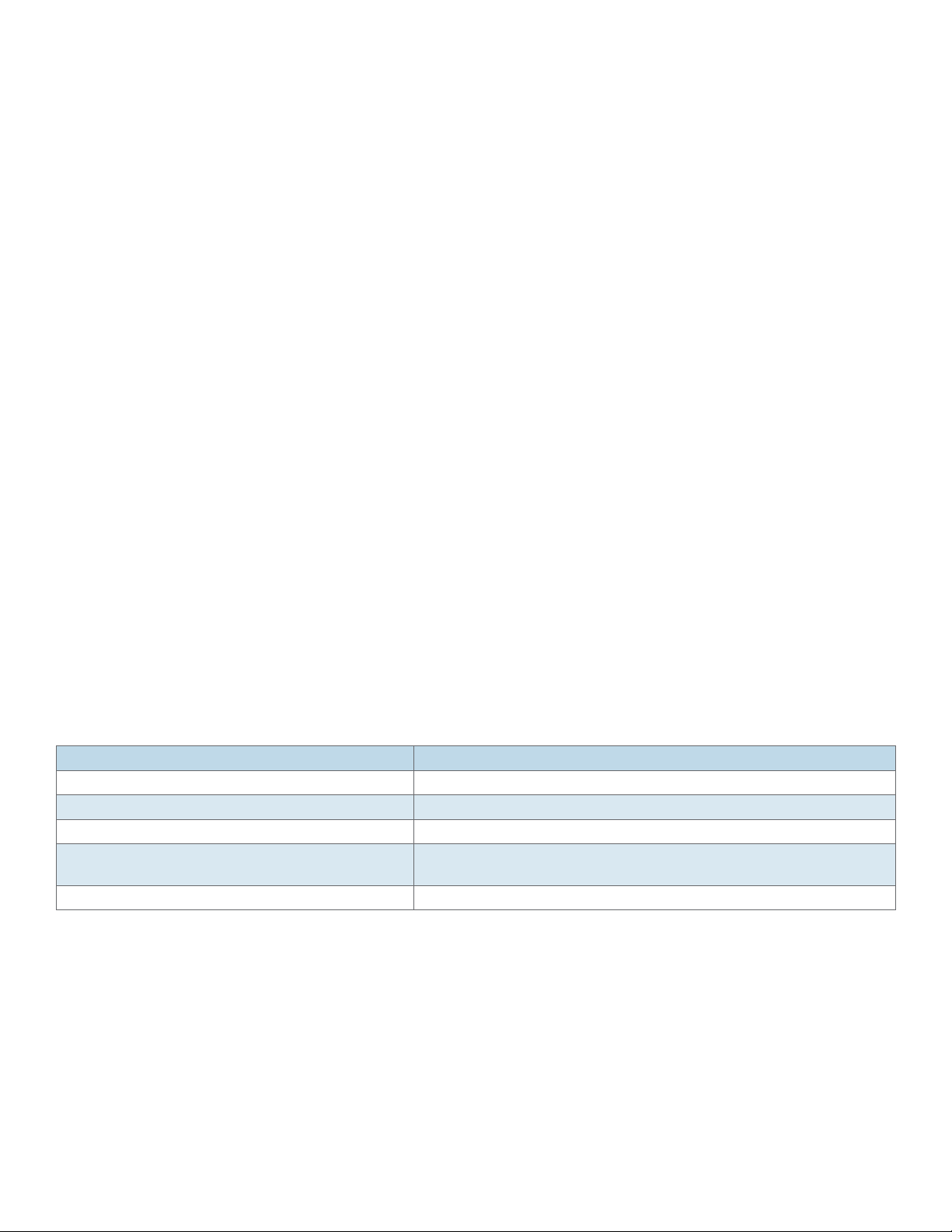
INSTALLATION AND OPERATION MANUAL RLGE2FE16R
VLANs of System Usage
The VLAN range of 4000-4093 is reserved for system internal usage and is not to be used or
manipulated by the user unless explicitly indicated in this manual.
VLAN Range of NMS Usage
NMS software may use a configurable range of VLANs for the creation and management of services.
The user should take notice to avoid manipulating NMS created VLANs.
VLAN Configuration Guidelines
» VLAN is enabled in the switch by default.
» The default VLAN 1 cannot be deleted in the switch, but the ports can be removed from it.
» Mapping of forwarding database identifier (FID) to VLANs is successful only when VLAN
learning mode is hybrid.
» To configure a static unicast/multicast MAC address in the forwarding database, VLAN and
member ports must have been configured for the specified VLAN.
» It is not possible to configure a port as trunk, if the port is an untagged member of a VLAN.
» Up to 1k VLANs may be configured simultaneously.
VLAN logically segments the shared media LAN, forming virtual workgroups. It redefines and
optimizes the basic Transparent Bridging functionalities such as learning, forwarding, filtering and
flooding.
VLAN Default State
Command Description
VLAN Module status Enable
Default VLAN Id configured in the switch 1
Mac address table aging time 300 seconds
Acceptable frame types All (Accepts untagged frames or priority-tagged frames or tagged
frames received on the port)
Ingress filtering Disabled
TECH SUPPORT: 1.888.678.9427
INS_RLGE2FE16R_REV– 10 Aug 2016 PAGE 96
Page 97

INSTALLATION AND OPERATION MANUAL RLGE2FE16R
Vlan Ports
Member ports represent the set of ports permanently assigned to the VLAN egress list. Frames
belonging to the specified VLAN are forwarded to the ports in the egress list.
The untagged setting allows the port to transmit the frames without a VLAN tag. This setting is
used to configure a port connected to an end user device.
NOTE: If the port type is not explicitly specified as untagged, then all the ports are configured to
be of tagged port type allowing transmission of frames with the specified VLAN tag.
NOTE: If PVID value has not been explicitly configured for a port, then PVID assumes a default
value of 1
NOTE: Adding port to a VLAN using the command “ports <type>..” will remove all ports from the
VLAN and associate only the detailed ports to the VLAN. Adding port to a VLAN using the
command “ports add <type>..” will add this port to the VLAN without affecting other port
members of the VLAN.
Enabling VLAN
A VLAN can be activated in two ways:
» By adding a member port to a VLAN (refer to section Configuring Static)
» By using the VLAN active command.
TECH SUPPORT: 1.888.678.9427
INS_RLGE2FE16R_REV– 10 Aug 2016 PAGE 97
Page 98

INSTALLATION AND OPERATION MANUAL RLGE2FE16R
Vlan command Hirarchy
+ root
+ config terminal
+ [no] vlan <vlan id>
- [no] ports <port type> <port IDs> [untagged <port type> <port IDs>]
- ports add <port type> <port IDs> [untagged <port type> <port IDs>]
- set unicast-mac learning { enable | disable | default}
- vlan active
- vlan unicast-mac learning limit <0-4294967295>
+ interface <type> <port id>
- [no] switchport pvid <vlan ID>
- port mac-VLAN
- mac-address-table static [unicast | multicast] <MAC> Vlan <id> recv port <type> <port id>
interface <type> <port id>
- switchport unicast-mac learning { enable | disable }
- switchport unicast-mac learning limit <0-4294967295>
+ interface vlan <vlan id>
- [no] shutdown
- ip address [dhcp | <ip-address> <subnet-mask>]
- Show vlan [brief | id <vlan-range> | summary ]
- show vlan device info
- show vlan port config [port <type> <port id>]
- show running-config vlan [<vlan id>]
- show mac-address table static [unicast | multicast ]
TECH SUPPORT: 1.888.678.9427
INS_RLGE2FE16R_REV– 10 Aug 2016 PAGE 98
Page 99

INSTALLATION AND OPERATION MANUAL RLGE2FE16R
Configuration Example
1. Setting all ports of the RLGE2FE16R to VLAN 1 as untagged members
config terminal
vla n 1
ports fastethernet 0/1-8 untagged fastethernet 0/1-8
ports add giga bitethernet 0/1-2 untagged gigabitethernet 0/1-2
exit
interface fastethernet 0/1
no shutdown
switchport pvid 1
exit
interface fastethernet 0/2
no shutdown
switchport pvid 1
exit
interface fastethernet 0/3
no shutdown
switchport pvid 1
exit
interface fastethernet 0/4
no shutdown
switchport pvid 1
exit
interface fastethernet 0/5
no shutdown
switchport pvid 1
exit
interface fastethernet 0/6
no shutdown
switchport pvid 1
exit
interface fastethernet 0/7
no shutdown
switchport pvid 1
exit
interface fastethernet 0/8
no shutdown
switchport pvid 1
exit
TECH SUPPORT: 1.888.678.9427
INS_RLGE2FE16R_REV– 10 Aug 2016 PAGE 99
Page 100

INSTALLATION AND OPERATION MANUAL RLGE2FE16R
interface gigabitethernet 0/1
no shutdown
switchport pvid 1
exit
interface gigabitethernet 0/2
no shutdown
switchport pvid 1
exit
end
write startup-cfg
2. VLAN configuration example
RLGE2FE16R# config terminal
RLGE2FE16R(config)# vlan 55
RLGE2FE16R(config-vlan)# ports fastethernet 0/1-4,0/7 untagged fastethernet 0/2,0/7
RLGE2FE16R(config-vlan)# end
3. VLAN configuration example
RLGE2FE16R# config terminal
RLGE2FE16R(config)# vlan 32
RLGE2F E16R(config-vla n)# vla n ac t iv e
RLGE2FE16R(config-vlan)# ports fastethernet 0/1-8 untagged all
RLGE2FE16R(config-vlan)# end
4. Configuration example for static Unicast entry configuring a Static Unicast Entry requires the
VLAN to be configured and the member ports for that specified VLAN must also be configured.
RLGE2FE16R(config)# mac-address-table static unicast 22:22:22:22:22:22 VLAN 2 recv-port
gigabitethernet 0/1 interface gigabitethernet 0/2
TECH SUPPORT: 1.888.678.9427
INS_RLGE2FE16R_REV– 10 Aug 2016 PAGE 100
 Loading...