

Page 1
INSTALLATION AND OPERATION MANUAL
RLGE2+1SMS Series
Electrical Substation-Rated
10/100/1000 Mbps 3-Port Self-managed Ethernet Switch
This manual serves the following
ComNet Model Numbers:
RLGE2+1SMS24DC
RLGE2+1SMS48DC
RLGE2+1SMSHV
The ComNet RLGE2+1SMS is designed for deployment in environments where high
levels of electromagnetic noise and interference (EMI) and severe voltage transients
and surges are routinely encountered.
The DIP-switch-selectable 100BASE-FX or 1000BASE-FX port supports conventional
CAT-5e/CAT-6 copper or optical transmission media by selection of the appropriate
ComNet SFP module.
User-selectable link fault pass-through provides remote indication of a network fault,
and a summary fault alarm provides a local or remote indication via Form C dry
contact closure in the event of loss of optical link or operating power.
The 10/100/1000BASE-TX ports support both auto-negotiation and automatic MDI/
MDI-X crossover for full and half-duplex operation; manual MDI/MDI-X switching is
not required.
The RLGE2+1SMS comes pre-programmed, preventing network video flooding with
DIP-switch selection of the SFP port as uplink or as an unmanaged switch.
LED indicators confirm operational status.
See Figures 1 – 8 for complete operation details.
The RLGE2+1SMS is DIN-rail or panel-mountable. See Figure A on the last page for
mounting instructions.
INS_RLGE2+1SMS_REV–
Rev. 27 Jun 2016
Page 2
INSTALLATION AND OPERATION MANUAL RLGE2+1SMS SERIES
INSTALLATION AND OPERATION MANUAL RLGE2+1SMS SERIES
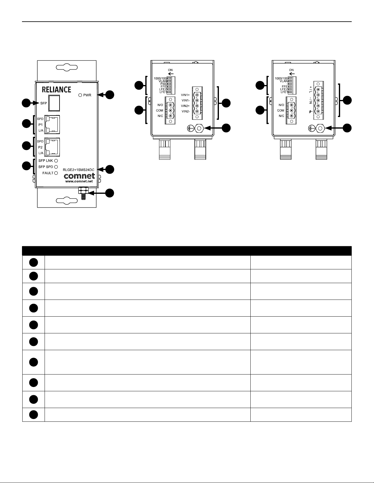
Figure 1 – RLGE2+1SMS Series
Front Panel
2
3
4
5
10
Figure 2 – RLGE2+1SMS24DC and
RLGE2+1SMS48DC Bottom Panel
7
6
9
8
10 10
1
Figure 3 – RLGE2+1SMSHV
Bottom Panel
7
9
8
Table 1 – RLGE2+1SMS24DC Physical Feature Descriptions
Call-out Description Manual Reference
1
Unit Model Number (Be sure to refer to any specific instructions for your unit variation) –
2
100/1000 Mbps SFP Fiber Optic Port (Fiber Type and Quantity are dependent on installed SFP) –
3
10/100/1000 TX RJ-45 Port 1 and Port 1 Link/Activity (L/A) and Speed LED Indicators
4
10/100/1000 TX RJ-45 Port 2 and Port 2 Link/Activity (L/A) and Speed LED Indicators
5
SFP Port Link Status and SFP Port Link Speed LED Indicators
6
Power LED Indicator
7
User-selectable DIP Switches
8
Fault Relay Connections
9
Power Connections
10
Chassis GND Lug See Installation Instructions, Step 4
See Installation Instructions, Step 6
See Table 5 - Indicating LEDs
See Installation Instructions, Step 6
See Table 5 - Indicating LEDs
See Installation Instructions, Step 7
See Table 4 - Indicating LEDs
See Installation Instructions, Step 8
See Table 4 - Indicating LEDs
See Installation Instructions, Steps 1 - 3
See Table 2 - DIP Switch Settings
See Figure 4 - DIP Switches
See Installation Instructions, Step 5
See Figure 6 - Fault Relay Operation
See Installation Instructions, Step 8
See Table 3 - Power Connections per Use Case
TECH SUPPORT: 1.888.678.9427
TECH SUPPORT: 1.888.678.9427
INS_RLGE2+1SMS_REV–
Rev. 27 Jun 2016 PAGE 2
Page 3

INSTALLATION AND OPERATION MANUAL RLGE2+1SMS SERIES
Installation Instructions
Figure 4 – DIP Switches
DIP Switches on RLGE2+1SMS24DC and
RLGE2+1SMS48DC Models
DIP Switches on RLGE2+1SMSHV Model
Table 2 – DIP Switch Settings
SW NAME OFF (DOWN) ON (UP)
1 Link Fault Enable Port 1 Link Fault Pass-Through Disabled Link Fault Pass-Through Enabled
2 Link Fault Enable Port 2 Link Fault Pass-Through Disabled Link Fault Pass-Through Enabled
3 FFE Fiber Fault Relay Disabled Fiber Fault Relay Enabled
4 PS Fault Enable Power Supply Fault Relay Disabled Power Supply Fault Relay Enabled
5 VLAN VLAN Disabled VLAN Enabled
6 1000/100 (SFP Speed)
1 - SET DATA RATE DIP SWITCHES
Locate the 100/1000 data rate DIP switch on the bottom panel of the unit.
Set the data rate according to bandwidth required.
NOTE: If two units are connected via the SFP Port, the data rate must be set the same on both units, and must match the
data rate of the installed SFPs. Data rate settings are read on start-up, so restart the unit after making any changes.
2 - SET FAULT DIP SWITCHES (UTP MODELS ONLY, FOR COAX MODELS SKIP TO STEP 3)
Locate the LFE1,LFE2, FFE, and PSE DIP switches on the bottom panel of the unit.
LFE1 or LFE 2: If the Copper Port is Down or Not Connected, the Optical Port will turn on and off at a ~1 sec rate to indicate
copper port fault and the alarm relay will be triggered.
FFE: If the optical link is lost or there is a power failure then the alarm relay output will be triggered.
NOTE: You may select multiple fault event triggers.
NOTE: Power Supply Fault DIP Switch is only available on Redundant Power Models. When a redundant power supply is
available, a failure of power on one power supply will trigger the alarm relay output.
NOTE: Restart not required when making changes to this DIP switch setting.
100 Mbps Speed Set Speed must match speed of installed
SFP. Reset power if switch or SFP is changed.
1000 Mbps Speed Set. Speed must match speed of installed SFP. Reset power if switch or SFP is changed.
3 - SET VLAN DIP SWITCH
If required, set the unit to provide port isolation. With VLAN enabled (ON), in the case of TX port isolation, the SFP port will act as
the uplink port. When two units are connected via fiber and both have VLAN enabled, traffic from Port 1 will go to Port 1 and traffic
from Port 2 will go to Port 2 only, functioning like two separate media converters over one fiber.
4 - CONNECT GROUND WIRING
Connect Ground Wiring to ground screw and tighten nut to secure.
5 - CONNECT FAULT RELAY WIRING
Connect Fauly Relay device to 3-pin terminal block. The COM to N/O will be shorted in the fault condition.
6 - CONNECT DATA WIRING
Connect RJ-45 Ports to field wiring using Cat5/5e/6 cable.
7 - CONNECT NETWORK WIRING
Using fiber optic cabling appropriate to the installed SFP, connect the unit to a network device.
TECH SUPPORT: 1.888.678.9427
INS_RLGE2+1SMS_REV–
Rev. 27 Jun 2016 PAGE 3
Page 4

INSTALLATION AND OPERATION MANUAL RLGE2+1SMS SERIES
INSTALLATION AND OPERATION MANUAL RLGE2+1SMS SERIES
Installation Instructions (Continued)
8 - CONNECT POWER
Connect power to unit per the following table.
Table 3 – Power Connections per Use Case
Operating Voltage
Use Power Connectors
Contact the ComNet Design Center, or refer to the appropriate installation and operation manual when configuring and specifying power for a deployment.
9 - VERIFY FUNCTIONALITY
See LED Indicator table below and Troubleshooting Guide if corrective action is needed.
RLGE2+1SMS24DC RLGE2+1SMS48DC RLGE2+1SMSHV
Redundant Inputs
9 to 36 VDC (max)
Vin1+ and Vin1- for PS 1
Vin2+ and VIN2- for PS 2
Redundant Inputs
36 to 59 VDC (max)
Vin1+ and Vin1- for PS 1
Vin2+ and VIN2- for PS 2
88 to 300 VDC (max)
OR
85 to 264 VAC (max)
+/L, -/N, and Earth GND
Table 4 – Front Panel LED Indicators
SFP Link SFP Speed Fault Power
GREEN Solid Communication link has been established
over optical fiber. Flashes when data is
being transmitted.
Flashing Fiber failure or copper failure (Link Fault
Enable must be switched set to ON)
RED Solid – 100 Mbps Fault (NO-COM) –
OFF Communication link has not been
established.
1000 Mbps No Fault (NC-
COM)
– – –
Unit is not correctly powered up or DIP
Switch incorrectly set.
(Reset power after switch change.)
Unit is not
correctly
powered up
Power Applied
Unit is not
correctly
powered up
Figure 5 – Electrical Port
Ethernet
Speed
Ethernet
Link /
Activity
Table 5 – Electrical Port LED Indicators
Link / Activity
GREEN Solid Communication link has been established over the electrical cable –
Flashing Data is being transmit ted over the electrical cable –
YELLOW – 1000 Mbps Speed
OFF Communication link has not been established. 10/100 Mbps Speed
Speed
Figure 6 - Fault Relay Operation
The fault relay is normally closed and will open on any of the following alarm conditions:
- Link Fault is enabled on the remote RLGE2+1SMS unit and the corresponding copper port has been
disconnected.
- Link Fault is enabled on the local RLGE2+1SMS unit and the corresponding copper port has been
disconnected.
- Fiber Fault is enabled on the local RLGE2+1SMS unit and the fiber link is down or the power has been lost
to either the local or remote RLGE2+1SMS unit.
Table 6 – Troubleshooting Guide
Problem Steps to Take
Power LED not lighting Check that power is properly applied to the unit using the correct connector pair.
No Communication Check Ethernet Link LEDs, Fiber Optic Link LEDs. Confirm Connections, DIP switches are set properly. Verify that the Data Rate switches are set
to the same data rate on back-to-back units and match the installed SFP. Restart the unit if the Data Rate Switch or installed SFP has changed.
TECH SUPPORT: 1.888.678.9427
INS_RLGE2+1SMS_REV–
Rev. 27 Jun 2016 PAGE 4
Page 5

INSTALLATION AND OPERATION MANUAL RLGE2+1SMS SERIES
Figure 7 – VLAN Disabled
Traffic can be sent/received on all electrical and fiber ports. VLAN is disabled on both units in back-to-back operation.
Port 1
All traffic
Port 2
All traffic
Port 1
All traffic
Port 2
All traffic
Figure 8 – VLAN Enabled
Traffic from Port 1 will go only to Port 1 and traffic from Port 2 will go only to Port 2 only, functioning like two separate media
converters over one fiber. VLAN is enabled on both units in back-to-back operation.
Port 1
Port 1 traffic only
Port 2
Port 2 traffic only
TECH SUPPORT: 1.888.678.9427
Port 1
Port 1 traffic only
Port 2
Port 2 traffic only
INS_RLGE2+1SMS_REV–
Rev. 27 Jun 2016 PAGE 5
Page 6

MECHANICAL INSTALLATION INSTRUCTIONS
Installation Considerations
This product is supplied as Standalone/Surface Mount module. Units should be installed in dry locations protected from extremes of temperature and humidity.
WARNING: Unit is to be used with a Listed Class 2 power supply.
IMPORTANT SAFEGUARDS:
A) Elevated Operating Ambient - If installed in a closed or multi-unit rack assembly, the operating ambient temperature of the rack environment may be greater than
room ambient. Therefore, consideration should be given to installing the equipment in an environment compatible with the maximum ambient temperature (Tma)
specified by the manufacturer.
B) Reduced Air Flow - Installation of the equipment in a rack should be such that the amount of air flow required for safe operation of the equipment is not compromised.
Figure A
Dimensions and mounting methods for a ComNet Reliance mini DIN Rail module
3 CORPORATE DRIVE | DANBURY, CT 06810 | USA
T: 203.796.5300 | F: 203.796.5303 | TECH SUPPORT: 1.888.678.9427 | INFO@COMNET.NET
8 TURNBERRY PARK ROAD | GILDERSOME | MORLEY | LEEDS, UK LS27 7LE
T: +44 (0)113 307 6400 | F: +44 (0)113 253 7462 | INFO-EUROPE@COMNET.NET
© 2016 Communications Ne tworks, LLC. All Rights Reser ved. “ComNet ” and the “ComNet L ogo” are registered trademarks of C ommunication Networ ks, LLC.
INS_RLGE2+1SMS_REV–
Rev. 27 Jun 2016 PAGE 6
 Loading...