

Comnet RL1000GW-AC-ESFP-S24, RL1000GW-AC-ESFP-S22, RL1000GW-AC-ESFP-S24-CEU, RL1000GW-AC-ESFP-S22-CEU, RL1000GW-AC-ESFP-S24-CNA User Manual
...Page 1
INSTALLATION AND OPERATION MANUAL
RL1000GW
Small Form Factor Substation-Rated Secure Ethernet
Layer 3 Router/Gateway with Optional 2G/3G/4G LTE Cellular
Radio Link, and 100/1000 Mbps SFP Uplink Port
ComNet product series RL1000GW are substation-rated and industrially hardened
layer 3 router/gateways, with a unique and highly robust packet processing SCADAaware security firewall for the most mission-critical and demanding cyber-security
applications. The RL1000GW is intended for deployment in environments where
high levels of electromagnetic noise and interference (EMI) and severe voltage
transients and surges are routinely encountered, such as electrical utility substations
and switchyards, heavy manufacturing facilities, track-side electronic equipment,
and other difficult out-of-plant installations. Layer 3 routing functionality allows for
the participation and foundation of a core network infrastructure. The compact-sized
DIN-rail mountable RL1000GW is ideally suited to those installations and applications
where space may be limited. These features make the RL1000GW an effective
platform for deploying a secure communications and networking gateway for remote
electrical utility sites, and other critical infrastructure applications.
The RL1000GW is an ideal platform for deploying a secure communications and
networking gateway for remote electrical utility sites, and other critical infrastructure
applications.
Page 2

INSTALLATION AND OPERATION MANUAL RL1000GW
Contents
About This Guide 8
Intended Audience 8
Related Documentation 9
About ComNet 9
Website 9
Support 9
Safety 9
Over view 10
Introduction 10
Key Features 10
Hardware and Interfaces 14
Graphic View of Hardware 16
Distance kept for natural air flow 17
Logical Structure 17
Grounding 17
Connecting to a Power Source 18
Power Budget 18
Configuration Environment 19
Command Line Interface 19
Supported Functionalities 20
System Version and Data Base 24
Configuration Database 24
OS VERSION 25
Commands Hierarchy 25
Example 26
Safe Mode 28
Ethernet Port Interfaces 32
TECH SUPPORT: 1.888.678.9427
Safe mode view 29
SW Image Installation 30
Commands Hierarchy 32
Show example 33
INS_RL1000GW_REV– 15 Jul 2016 PAGE 2
Page 3

INSTALLATION AND OPERATION MANUAL RL1000GW
Login and Management 35
Serial Console Port 35
Connecting to the Console Port 35
CLI Terminal Commands 36
Management 36
Default state 36
Commands Hierarchy 37
Commands Description 38
IP Interfaces 39
Interface Assignment Rules 39
IP interface id 41
IP interface VLAN id 41
IP Interface Commands Hierarchy 41
IP Interface Commands Description 42
Example 43
Diagnostic 46
System logs export 46
Commands Hierarchy 46
Commands Description 46
Capture Ethernet service traffic 47
Commands Hierarchy 47
Commands Description 47
Example 47
Syslog 49
The Priority indicator 50
Message Format 51
Commands Hierarchy 58
Output example 59
Discrete IO Channels 60
TECH SUPPORT: 1.888.678.9427
Interfaces 60
Diagnostics and logic states 60
Technical data 61
Discrete IO Channels Commands Hierarchy 61
Discrete IO Channels Commands 61
INS_RL1000GW_REV– 15 Jul 2016 PAGE 3
Page 4

INSTALLATION AND OPERATION MANUAL RL1000GW
Clock and Time 62
Local Clock 62
TACACS 63
Default Configurations 63
TACACS Command Hierarchy 64
TACACS Commands Descriptions 64
Configuration Example 65
ACLs 66
Flow of ACL Inspection 66
ACG 67
Comments 67
Example 68
ACL Commands Hierarchy 68
ACL Commands Descriptions
70
Configuration Example 71
QOS 72
QOS Commands Hierarchy 72
QOS Commands Descriptions
72
NAT 73
Networking 73
NAT Commands Hierarchy 74
NAT Commands Description 75
Example 75
OSPF 78
OSPF Commands Hierarchy 78
OSPF Commands Descriptions
79
Serial Ports and Services 83
TECH SUPPORT: 1.888.678.9427
OSPF setup example 79
Serial interfaces 83
Services configuration structure 83
Serial Commands Hierarchy 84
Serial Commands Description 85
INS_RL1000GW_REV– 15 Jul 2016 PAGE 4
Page 5

INSTALLATION AND OPERATION MANUAL RL1000GW
Declaration of ports 88
Default State 88
RS- 232 Port Pin Assignment 88
RS-232 Serial cable 89
RS-485 Port Pin Assignment 90
LED States 90
Transparent Serial Tunneling 91
Concept of Operation 91
Supported Network topologies 92
Point to multipoint point 93
Multi Point to multipoint point 94
Modes of Operation 94
Reference drawing 96
Serial Traffic Direction 97
Allowed latency 97
Tx Delay 98
Bus Idle Time 98
Example 1 98
Example 2 100
Protocol Gateway IEC 101 to IEC 104 102
Modes of Operation 102
IEC101/104 Gateway properties IEC 101 104
IEC101/104 Gateway Configuration 105
Gateway 101/104 Configuration Flow 106
Gateway 101/104 Commands Hierarchy 108
Gateway 101/104 Commands 110
Example Gateway 101/104 111
Terminal Server 114
TECH SUPPORT: 1.888.678.9427
Service Buffer Mode 116
Terminal Server Commands Hierarchy 117
Terminal Server Commands 119
Example local Service 121
Example Networking 124
INS_RL1000GW_REV– 15 Jul 2016 PAGE 5
Page 6

INSTALLATION AND OPERATION MANUAL RL1000GW
Modbus Gateway 126
Implementation 126
Modbus Gateway Commands Hierarchy 127
Modbus Gateway Commands Description 128
Example 129
DNP3 Gateway 132
Example 132
VPN 133
Background 133
Modes supported 133
Layer 3 DM-VPN 134
Layer 3 IPSec-VPN 135
DM-VPN Commands Hierarchy 136
IPSec-VPN Commands Hierarchy 137
IPSec 138
Applications 138
Authentication Header (AH) 138
Encapsulating Security Payload (ESP) 138
Security Associations 139
ISAK MP 139
IKE 139
ISAKMP Phase 2 147
IPSec Command Association 148
IPSec Commands Hierarchy 150
IPsec Commands 152
IPSec defaults 155
Cellular Modem 156
LTE Modem 156
TECH SUPPORT: 1.888.678.9427
GPRS/UMTS Modem 158
Interface Name 158
Method of operation 159
SIM card state 160
Backup and redundancy 162
Cellular Commands Hierarchy 163
Cellular Commands Description 164
INS_RL1000GW_REV– 15 Jul 2016 PAGE 6
Page 7

INSTALLATION AND OPERATION MANUAL RL1000GW
Default State 166
LED States 166
Example for retrieving the IMEI 167
Example for Sim Status 168
Discrete IO Channels 169
Discrete channel interface 169
Technical data 169
Discrete IO Channels Commands Hierarchy 170
Discrete IO Channels Commands 170
VPN Setup Examples 171
DM-VPN Setup 171
Network drawing 172
DM-VPN over Cellular Setup 176
Network drawing 177
Configuration 177
Testing the setup 181
Adding a terminal server service 184
Adding a transparent serial tunneling service 185
Application Aware Firewall 186
Firewall Service flow 186
Firewall Flow Illustration 187
Supported Hardware 187
Configuration 187
Example 188
Firewall Commands Hierarchy 189
Firewall Commands 190
TECH SUPPORT: 1.888.678.9427
INS_RL1000GW_REV– 15 Jul 2016 PAGE 7
Page 8

INSTALLATION AND OPERATION MANUAL RL1000GW
About This Guide
This user guide includes relevant information for utilizing the Reliance RL1000GW line of switches.
The information in this document is subject to change without notice and describes only the
product defined in the introduction of this document.
This document is intended for the use of customers of ComNet only for the purposes of the
agreement under which the document is submitted, and no part of it may be reproduced or
transmitted in any form or means without the prior written permission of ComNet.
The document is intended for use by professional and properly trained personnel, and the
customer assumes full responsibility when using it.
If the Release Notes that are shipped with the device contain information that conflicts with the
information in this document or supplements it, the customer should follow the Release Notes.
The information or statements given in this document concerning the suitability, capacity, or
performance of the relevant hardware or software products are for general informational purposes
only and are not considered binding. Only those statements and/or representations defined in the
agreement executed between ComNet and the customer shall bind and obligate ComNet.
ComNet however has made all reasonable efforts to ensure that the instructions contained in this
document are adequate and free of material errors. ComNet will, if necessary, explain issues which
may not be covered by the document.
ComNet sole and exclusive liability for any errors in the document is limited to the documentary
correction of errors. ComNet is not and shall not be responsible in any event for errors in
this document or for any damages or loss of whatsoever kind, whether direct, incidental, or
consequential (including monetary losses), that might arise from the use of this document or the
information in it.
This document and the product it describes are the property of ComNet, which is the owner of all
intellectual property rights therein, and are protected by copyright according to the applicable laws.
Other product and company names mentioned in this document reserve their copyrights,
trademarks, and registrations; they are mentioned for identification purposes only.
Copyright © 2016 Communication Networks, LLC. All rights reserved.
Intended Audience
This user guide is intended for network administrators responsible for installing and configuring
network equipment. Users must be familiar with the concepts and terminology of Ethernet and
local area networking (LAN) to use this User Guide.
TECH SUPPORT: 1.888.678.9427
INS_RL1000GW_REV– 15 Jul 2016 PAGE 8
Page 9

INSTALLATION AND OPERATION MANUAL RL1000GW
Related Documentation
The following documentation is also available:
» RL1000GW Data sheet
» RL1000GW Quick Start Guide
» RL1000GW_ES Enhanced Security Software Options Manual
» SFP Modules Data sheet
About ComNet
ComNet develops and markets the next generation of video solutions for the CCTV, defense, and
homeland security markets. At the core of ComNet’s solutions are a variety of high-end video
servers and the ComNet IVS software, which provide the industry with a standard platform for
analytics and security management systems enabling leading performance, compact and cost
effective solutions.
ComNet products are available in commercial and rugged form.
Website
For information on ComNet’s entire product line, please visit the ComNet website at
http://www.comnet.net
Support
For any questions or technical assistance, please contact your sales person (sales@comnet.net) or
the customer service support center (techsupport@comnet.net)
Safety
» Only ComNet service personnel can service the equipment. Please contact ComNet Technical
Support.
» The equipment should be installed in locations with controlled access, or other means of
security, and controlled by persons of authority.
TECH SUPPORT: 1.888.678.9427
INS_RL1000GW_REV– 15 Jul 2016 PAGE 9
Page 10
INSTALLATION AND OPERATION MANUAL RL1000GW
Overview
Introduction
The ComNet Service-aware Industrial Ethernet routers combine a ruggedized Ethernet platform
with a unique application-aware processing engine.
As an Industrial Ethernet router the ComNet RL1000GW provide a strong Ethernet and IP featureset with a special emphasis on the fit to the mission-critical industrial environment such as fit to the
harsh environment, high reliability and network resiliency.
In addition the ComNet routers have unique service-aware capabilities that enable an integrated
handling of application-level requirements such as implementation of security measures.
Such an integrated solution results in simple network architecture with an optimized fit to the
application requirements.
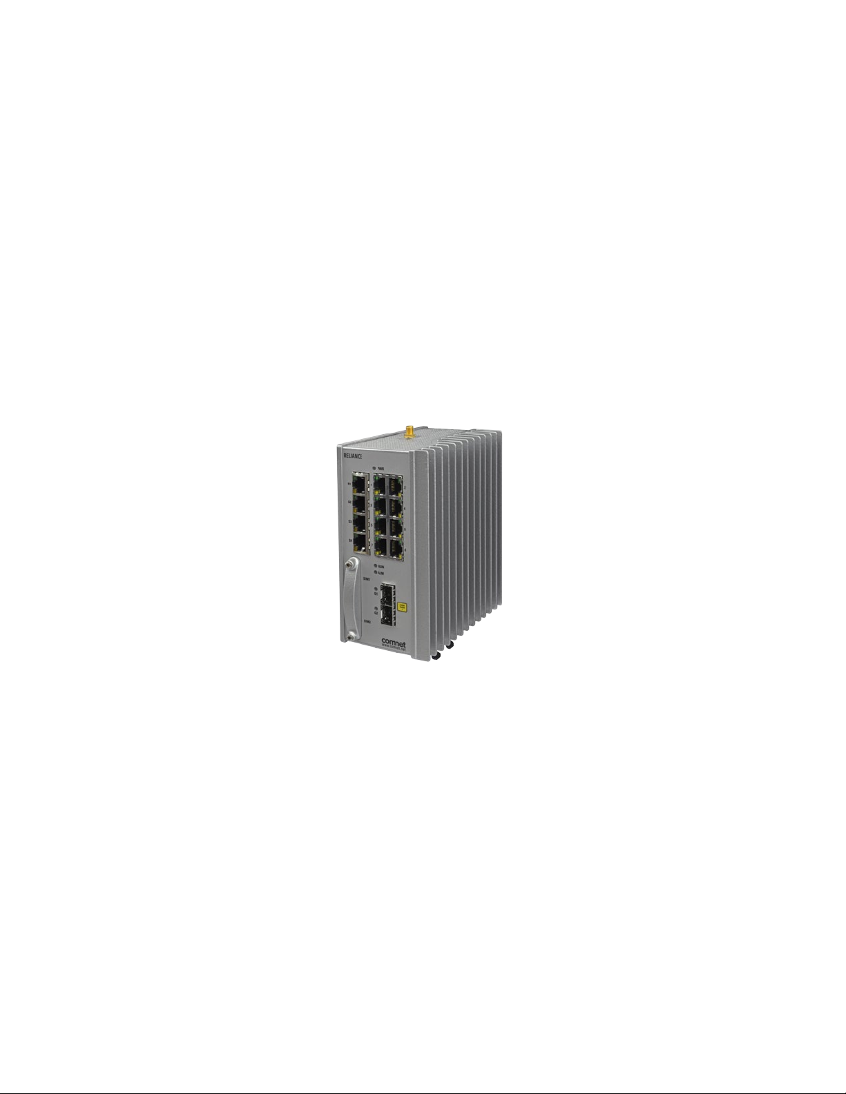
Figure 1 - Illustration of ComNet RL1000GW
Key Features
The ComNet RL1000GW devices offer the following features:
» Compact systems
» Advanced Router feature-set
» Integrated Defense-in-Depth tool-set
» Ethernet and Serial interfaces
» Fit to harsh industrial environment
TECH SUPPORT: 1.888.678.9427
INS_RL1000GW_REV– 15 Jul 2016 PAGE 10
Page 11

INSTALLATION AND OPERATION MANUAL RL1000GW
Seamless & Reliable Connection to Any Network
The RL1000GW provides connectivity to any copper, fiber optic, or cellular radio-based Ethernet
network. Fiber optic networks are supported by the use of the optional 100/1000FX SFP uplink
port. The optional highly resilient 2G/3G/4G LTE cellular radio uplink with 2 SIM card slots for
network redundancy, is ideal where fiber optic infrastructure is not available, and may be used as
a back-up link for those applications where interruption of service is not tolerable.
Extremely Effective Network Security, For the Most Mission-Critical Applications
Service Gateway
The RL1000GW service gateway includes a highly robust application layer, and provides legacy
support, a Deep Packet Inspection (DPI) application-aware SCADA firewall, serial tunnelling,
protocol gateway, and extremely effective encryption technologies. The service gateway offers a
uniquely capable feature set which may serve as the hardware foundation to a secure industrial
controls network, and includes Protocol Gateway, VPN, and IPsec features.
Protocol Gateway
Gateway functionality between a DNP3 TCP client (master) and a DNP3 Serial RTU, IED, PLC, or
other compatible device is supported. This same functionality is supported across MODBUS TCP
to MODBUS RTU, and IEC 61850 101/104 TCP to IEC 61850 101/104 RTU. This level of protocol
conversion allows legacy protocols to be secured by enterprise and industry best practice level
encryption across a TCP IP-based network.
VPN
VPN tunnels are included for secure inter-site connectivity with IPsec, DM-VPN, and VPN GRE
tunnels with key management certificates. The supported VPN modes allow both layer-2 and layer3 services, to best suit the user’s application-specific cyber-protection needs.
IPSec
Internet Protocol Security (IPsec) is a protocol suite for securing Internet Protocol (IP) communications
by authenticating and/or encrypting each IP packet of a communication session. IPsec-VPN as well
as IPsec encryption are supported over other VPN technologies. By implementing this level of
industry-accepted encryption, data may traverse the network in a guaranteed delivery method, as
well as providing a cohesive and secure methodology for network communication across legacy and
modern networks.
Identity Management and Authentication Proxy Access (APA)
NERC-CIP-5 defines the important requirement for network security protection of remote and
unattended facilities. The capability of identifying the user and creating specific network privileges
per identified and authenticated user prior to granting the user access to the network therefore
becomes critical
The Authentication Proxy Access (APA) is a highly sophisticated security feature, which allows the
network operator to manage the substation or any other facility maintenance process. This feature
TECH SUPPORT: 1.888.678.9427
INS_RL1000GW_REV– 15 Jul 2016 PAGE 11
Page 12

INSTALLATION AND OPERATION MANUAL RL1000GW
gives full control of the maintenance process to the operator by granting the capability to create
dynamic policies to specific tasks within an explicitly defined time window. Following this time
window, operators receive reporting on activities performed during the task. This audit trail comes
in the form of an overview log, and a full packet capture (PCAP) of the session.
Before a user is allowed access to the network, they must log in to ComNet’s internal authentication
process with their unique user name and password. Upon validation of the user profile, specific
access is granted to predefined devices and functions, and each operation is logged. Multi-factor
authentication is available when combined with the Cyber-Physical Integration feature.
X.509 Certificate Exchange for VPN Connections
VPN tunnels for secure inter-site connectivity with IPsec VPN, GRE Tunnels, and DMVPN
technologies are fully supported. In addition to IPsec encryption, X.509 key management
certificates are provided. This certificate support allows for a secure signed key exchange
between a Certificate Authority, and two secure nodes. Having a third-party authority as a signing
participant offers end-to-end security that may be managed and reissued from a trusted central
source within the user’s network.
Cyber-Physical Integration
Integrated within the enhanced-security RL1000GW, is a physical identity server system,
allowing the use of external authentication hardware, such as magnetic card readers, biometric
identification sensors, facial recognition cameras, etc., to create a two-factor authentication to
the APA feature. This provides an additional level of validation of the user and his/her credentials,
prior to granting the user network access. Once the authentication is validated and approved, a
set of defined policies allow the authenticated technician to perform their task.
Enhanced SCADA-Aware Firewall
A whitelist-based firewall is provided for every Ethernet and serial data port, so full firewall
protection is available at all remote sites within the network. Every SCADA protocol packet (IEC
61850, DNP3 RTU/TCP, ModBus RTU/TCP, and IEC 101/104) is scanned and validated by the
firewall engine for its source and destination, as well as its protocol and packet content.
The structure of the distributed firewall allows the creation of a unique firewall at each access point
to the network. This is critical for securing against insider cyber-attacks, compromised field devices,
man-in-the-middle attacks, and a myriad of alternate attack vectors, by providing a secure baseline.
Two firewall states are included: Monitoring, and enforcing. The monitoring state provides an
alarm at the control center for any network violation, without blocking the network traffic. The
enforcing state is extremely effective for blocking suspicious traffic, while also triggering a
violation alarm at the control center.
DPI (Deep Packet Inspection) SCADA Protocols Firewall
ComNet’s distributed DPI firewall ensures that the operator will have full control over the network,
even when faced with a sophisticated attempt at breaching the network. Monitoring SCADA
commands, this highly robust whitelist-based firewall analyses SCADA network traffic, and is
TECH SUPPORT: 1.888.678.9427
INS_RL1000GW_REV– 15 Jul 2016 PAGE 12
Page 13

INSTALLATION AND OPERATION MANUAL RL1000GW
provided for every Ethernet and serial data port, so full firewall protection is available at all remote
sites within the network, as well as all IEDs, RTUs, PLCs, or any other device connected to the
network. Every SCADA protocol packet (IEC 61850, DNP3 RTU/TCP, ModBus RTU/TCP, and IEC
101/104) is scanned and validated by the firewall engine for its source and destination, as well as
its protocol and its specific packet
Any detected abnormal traffic behavioral patterns are blocked, any affected subnets are isolated,
and alerts are automatically generated.
Ease of Installation and Network Integration
High levels of cyber-security experience are not required to successfully deploy the RL1000GW. It
is fully supported by ComNet’s Reliance Product Configuration Utility and CLI, allowing the secure
switch/router to be easily configured, and to diagnose network and security functions.
Configuration of the secure firewall is also simple. Once connected to the user’s network, the
RL1000GW immediately begins to collect and analyse information across the network, including
from other connected devices, traffic behavior, etc. Recommended firewall rules are then
suggested to the user; the implementation of these rules is optional, and they can be easily edited
using the Configuration Utility.
OAM (IEEE 802.3-2005 & IEEE 802.1ag) and QoS are also supported. Strict priority, Weighted Round
Robin (WRR), ingress policing, and egress traffic shaping are included for traffic management.
Serial Data Interface
The 2-port serial interface is available for applications including terminal server with protocol
gateway and serial tunnelling functionality, and provides direct connectivity to legacy RS-232 or
4-wire RS-485 serial data IEDs, RTUs, PLCs, and other devices.
TECH SUPPORT: 1.888.678.9427
INS_RL1000GW_REV– 15 Jul 2016 PAGE 13
Page 14

INSTALLATION AND OPERATION MANUAL RL1000GW
Hardware and Interfaces
Depending on the RL1000GW hardware variant ordered your router will hold physical Ethernet
and Serial ports.
» Serial, RJ 45 ports are RS-232. Max 2 ports
» Serial, RJ 45 ports are RS-485. Max 1 ports
» Ethernet RJ45 copper ports are 10/100 FE. One port
» Ethernet SFP based ports are 100/1000 GE. One port.
Ordering options of Hardware
RL1000GW Standard Models
Part Number Description
RL1000GW/12/E/S22 RL1000GW with 2 x RS-232 and 1 x 10/100 Tx, 12/24V DC
RL1000GW/12/E/S24 RL1000GW with 1 x RS-232, 1 x RS-485 and 1 x 10/100 Tx, 12/24 VDC
RL1000GW/12/ESFP/S22 RL1000GW with 2 x RS-232, 1 x 10/100 Tx and 1 x 100/1000 Fx SFP, 12/24 VDC
RL1000GW/12/ESFP/S24 RL1000GW with 1 x RS-232, 1 x RS-485, 1 x 10/100 Tx and 1 x 100/1000 Fx SFP, 12/24 VDC
RL1000GW/12/E/S22/CH+ RL1000GW with 2 x RS-232, 1 x 10/100 Tx and 2G/3G/HSPA+ Cellular Modem, 12/24 VDC
RL1000GW/12/E/S24/CH+
RL1000GW/12/ESFP/S22/CH+
RL1000GW/12/ESFP/S24/CH+
RL1000GW/12/E/S22/CNA RL1000GW with 2 x RS-232, 1 x 10/100 Tx and 4G LTE Cellular Modem (NA Bands), 12/24 VDC
RL1000GW/12/E/S24/CNA
RL1000GW/12/ESFP/S22/CNA
RL1000GW/12/ESFP/S24/CNA
RL1000GW/12/E/S22/CEU RL1000GW with 2 x RS-232, 1 x 10/100 Tx and 4G LTE Cellular Modem (EU Bands), 12/24 VDC
RL1000GW/12/E/S24/CEU
RL1000GW/12/ESFP/S22/CEU
RL1000GW/12/ESFP/S24/CEU
RL1000GW/48/E/S22 RL1000GW with 2 x RS-232 and 1 x 10/100 Tx, 24/48V DC
RL1000GW/48/E/S24 RL1000GW with 1 x RS-232, 1 x RS-485 and 1 x 10/100 Tx, 24/48 VDC
RL1000GW/48/ESFP/S22 RL1000GW with 2 x RS-232, 1 x 10/100 Tx and 1 x 100/1000 Fx SFP, 24/48 VDC
RL1000GW/48/ESFP/S24 RL1000GW with 1 x RS-232, 1 x RS-485, 1 x 10/100 Tx and 1 x 100/1000 Fx SFP, 24/48 VDC
RL1000GW/48/E/S22/CH+ RL1000GW with 2 x RS-232, 1 x 10/100 Tx and 2G/3G/HSPA+ Cellular Modem, 24/48 VDC
RL1000GW with 1 x RS-232, 1 x RS-485, 1 x 10/100 Tx and 2G/3G/HSPA+ Cellular Modem,
12/24 VDC
RL1000GW with 2 x RS-232, 1 x 10/100 Tx, 1 x 100/1000 Fx SFP and 2G/3G/HSPA+ Cellular
Modem, 12/24 VDC
RL1000GW with 1 x RS-232, 1 x RS-485, 1 x 10/100 Tx, 1 x 100/1000 Fx SFP and 2G/3G/HSPA+
Cellular Modem, 12/24 VDC
RL1000GW with 1 x RS-232, 1 x RS-485, 1 x 10/100 Tx and 4G LTE Cellular Modem (NA Bands),
12/24 VDC
RL1000GW with 2 x RS-232, 1 x 10/100 Tx, 1 x 100/1000 Fx SFP and 4G LTE Cellular Modem
(NA Bands), 12/24 VDC
RL1000GW with 1 x RS-232, 1 x RS-485, 1 x 10/100 Tx, 1 x 100/1000 Fx SFP and 4G LTE
Cellular Modem (NA Bands), 12/24 VDC
RL1000GW with 1 x RS-232, 1 x RS-485, 1 x 10/100 Tx and 4G LTE Cellular Modem (EU Bands),
12/24 VDC
RL1000GW with 2 x RS-232, 1 x 10/100 Tx, 1 x 100/1000 Fx SFP and 4G LTE Cellular Modem
(EU Bands), 12/24 VDC
RL1000GW with 1 x RS-232, 1 x RS-485, 1 x 10/100 Tx, 1 x 100/1000 Fx SFP and 4G LTE
Cellular Modem (EU Bands), 12/24 VDC
TECH SUPPORT: 1.888.678.9427
INS_RL1000GW_REV– 15 Jul 2016 PAGE 14
Page 15

INSTALLATION AND OPERATION MANUAL RL1000GW
Part Number Description
RL1000GW/48/E/S24/CH+
RL1000GW/48/ESFP/S22/CH+
RL1000GW/48/ESFP/S24/CH+
RL1000GW/48/E/S22/CNA RL1000GW with 2 x RS-232, 1 x 10/100 Tx and 4G LTE Cellular Modem (NA Bands), 24/48 VDC
RL1000GW/48/E/S24/CNA
RL1000GW/48/ESFP/S22/CNA
RL1000GW/48/ESFP/S24/CNA
RL1000GW/48/E/S22/CEU RL1000GW with 2 x RS-232, 1 x 10/100 Tx and 4G LTE Cellular Modem (EU Bands), 24/48 VDC
RL1000GW/48/E/S24/CEU
RL1000GW/48/ESFP/S22/CEU
RL1000GW/48/ESFP/S24/CEU
RL1000GW with 1 x RS-232, 1 x RS-485, 1 x 10/100 Tx and 2G/3G/HSPA+ Cellular Modem,
24/48 VDC
RL1000GW with 2 x RS-232, 1 x 10/100 Tx, 1 x 100/1000 Fx SFP and 2G/3G/HSPA+ Cellular
Modem, 24/48 VDC
RL1000GW with 1 x RS-232, 1 x RS-485, 1 x 10/100 Tx, 1 x 100/1000 Fx SFP and 2G/3G/HSPA+
Cellular Modem, 24/48 VDC
RL1000GW with 1 x RS-232, 1 x RS-485, 1 x 10/100 Tx and 4G LTE Cellular Modem (NA Bands),
24/48 VDC
RL1000GW with 2 x RS-232, 1 x 10/100 Tx, 1 x 100/1000 Fx SFP and 4G LTE Cellular Modem
(NA Bands), 24/48 VDC
RL1000GW with 1 x RS-232, 1 x RS-485, 1 x 10/100 Tx, 1 x 100/1000 Fx SFP and 4G LTE
Cellular Modem (NA Bands), 24/48 VDC
RL1000GW with 1 x RS-232, 1 x RS-485, 1 x 10/100 Tx and 4G LTE Cellular Modem (EU Bands),
24/48 VDC
RL1000GW with 2 x RS-232, 1 x 10/100 Tx, 1 x 100/1000 Fx SFP and 4G LTE Cellular Modem
(EU Bands), 24/48 VDC
RL1000GW with 1 x RS-232, 1 x RS-485, 1 x 10/100 Tx, 1 x 100/1000 Fx SFP and 4G LTE
Cellular Modem (EU Bands), 24/48 VDC
Options
Optional Part No Description
ANT3G-2M 2G/3G External Grade Cellular Antenna with 2M cable (1 required per switch)
ANT3G-5M 2G/3G External Grade Cellular Antenna with 5M cable (1 required per switch)
ANT4G - 2M 4G LTE External Grade Cellular Antenna with 2M cable (2 required per switch)
ANT4G - 5M 4G LTE External Grade Cellular Antenna with 5M cable (2 required per switch)
Power Supply 12 V, 24 V or 48 V DC DIN Rail power supply
Conformal Coat Add suffix ‘/C’ for Conformally Coated Circuit Boards to extend to condensation conditions
SFP Modules¹ User selection of ComNet SFP (See SFP Modules data sheet for product numbers and compatibility)
DINBKT3 19-inch rack mount panel adapter
TECH SUPPORT: 1.888.678.9427
INS_RL1000GW_REV– 15 Jul 2016 PAGE 15
Page 16
INSTALLATION AND OPERATION MANUAL RL1000GW
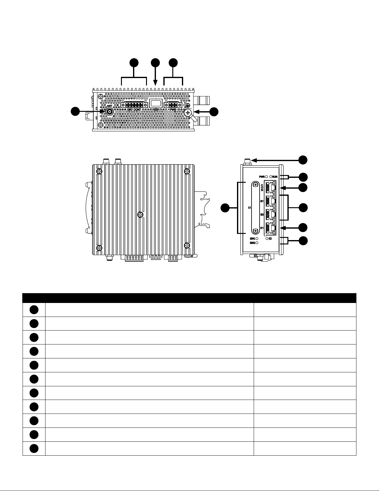
Graphic View of Hardware
8
1
10
9
11
1
3
4
2
5
6
7
Figure 2 – RL1000GW Product
Table 1 – RL1000GW Physical Feature Descriptions
Call-out Description Manual Reference
1
Antenna Female Connection –
2
SIM Card Ports 1 - 2
3
Power and Run LED Indicators
4
Console Interface, Link/Activity (L/A) and Speed LED Indicators
5
RS-232 Ports 1 - 2, Link/Activity (L/A) and Speed LED Indicators
6
10/100 TX Port, Link/Activity (L/A) and Speed LED Indicators
7
SIM1, SIM2, Fast Ethernet Port LED Indicators
8
Dry Contact DI/DO Interface
9
USB Interface
10
Power Interface
11
Chassis GND Lug
TECH SUPPORT: 1.888.678.9427
INS_RL1000GW_REV– 15 Jul 2016 PAGE 16
Page 17
INSTALLATION AND OPERATION MANUAL RL1000GW
Distance kept for natural air flow
Proper installation depends on natural air flow for cooling. You must maintain a 10cm distance
above and below the ComNet switch for proper air flow.
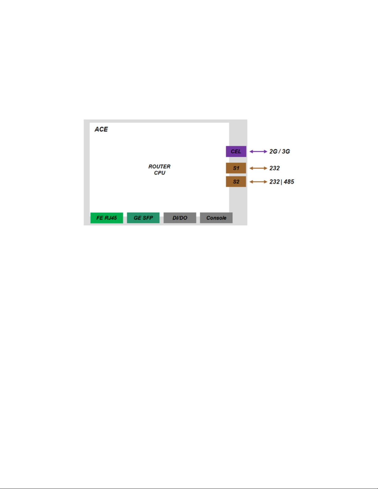
Logical Structure
Figure 4 - Logical system view, illustration
Grounding
To install the grounding wire:
» Prepare a minimum 10 American Wire Gauge (AWG) grounding wire terminated by a crimped
two-hole lug with hole diameter and spacing as shown in the below figure. Use a suitable
crimping tool to fasten the lug securely to the wire. Adhere to your company’s policy as to the
wire gauge and the number of crimps on the lug.
» Apply some anti-oxidant onto the metal surface.
» Mount the lug on the grounding posts, replace the spring-washers and fasten the bolts. Avoid
using excessive torque.
CAUTION – Do not remove the earth connection unless all power supply connections are
disconnected.
DANGER – Before connecting power to the platform, make sure that the grounding posts are
firmly connected to a reliable ground, as described below.
TECH SUPPORT: 1.888.678.9427
INS_RL1000GW_REV– 15 Jul 2016 PAGE 17
Page 18
INSTALLATION AND OPERATION MANUAL RL1000GW
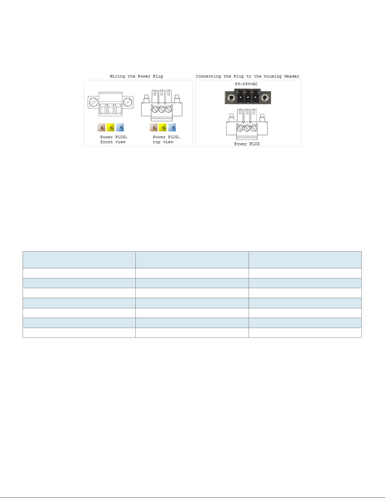
Connecting to a Power Source
Wiring AC Input voltage connector
For an AC product variant there is a single input connector.
Use a Brown wire for the Line (Phase) conductor, a Green/Yellow for the grounding and a Blue wire
for the Neutral conductor. use 18AWG (1mm2) wire, with insulated ferrules.
Power Budget
The following table details power consumption of the Hardware variants with cellular and serial
interfaces.
Unit Power feed Max Power [Watt] Version without POE
ports
12vDC 18. 5 80
24vDC 18.5 100
48vDC 18.5 140 (or 260*)
110 vD C 18.5 120
220vDC 18.5 120
110 vAC 20.35 149
220vAC 20.35 149 (or 275*)
* Refers to specific ordering option supporting 240w PoE.
Max Power [Watt] Version with POE
ports
TECH SUPPORT: 1.888.678.9427
INS_RL1000GW_REV– 15 Jul 2016 PAGE 18
Page 19

INSTALLATION AND OPERATION MANUAL RL1000GW
Configuration Environment
A CLI based configuration environment is available for the user.
Command Line Interface
The CLI (Command Line Interface) is used to configure the RL1000GW from a console attached to
the serial port of the router or from a remote terminal using SSH. The following table lists the CLI
environments and modes.
Table 3-1: Command Line Interface
Command
Mode
Global
Configuration
Environment
(GCE)
Global
Hierarchy
Configuration
Application
Configuration
Environment
(ACE)
ACE Config Use the command ‘configure’ to
Application
Hierarchy
Configuration
Access Method Prompt Exit Method
Following user log in this mode
is available to the user.
From the Global Configuration
mode command you may drill
down to specific feature sub
tree.
Example is shown here for
router configuration sub tree.
The ACE is an alternative
configuration environment for
supported features
access the ACE Configuration
mode
Access the target feature. For
example :
‘interface vlan 1’
RL1000GW# To exit this mode would mean the user to log out
from the system.
Use the command ‘exit’
[router/] To exit one level back, the ‘..’ (Two dots) is used.
ACE# This mode is not supported at current version
To exit back to the GCE mode use the ‘exit’
command.
ACE(config)# To exit back to the ACE mode use the ‘exit’
command.
ACE(config-if-eth1.1)# To return one level up use ‘exit’.
To return to the ACE use ‘end’.
TECH SUPPORT: 1.888.678.9427
INS_RL1000GW_REV– 15 Jul 2016 PAGE 19
Page 20

INSTALLATION AND OPERATION MANUAL RL1000GW
Supported Functionalities
The RL1000GW is a feature rich industrial router supporting:
» L3 dynamic and static Routing.
» SCADA services.
» Firewall.
» Secure networking.
The below table gives a high level view of the supported features.
Feature Set
TFTP Ethernet ports Serial ports Cellular modem
OSPF Vlan tagging IPSec VPN
Management Authentication SCADA Gateway SCADA Firewall
L3-L4 Firewall QOS Serial services Terminal services
NAT Syslog OSPF RIP*
DHCP Client
TECH SUPPORT: 1.888.678.9427
INS_RL1000GW_REV– 15 Jul 2016 PAGE 20
Page 21

INSTALLATION AND OPERATION MANUAL RL1000GW
The below table details the RL1000GW planned features.
Group Feature
Interfaces Cellular modem with 2 SIM cards X
FE RJ45 Ports X
Fiber Optic port X
Gigabit port X
RS 232 ports X
RS 485 4wire ports X
SFP Port X
Auto Crossing X
Auto Negotiation IEEE 802.3ab X
VLAN segregation Tagging IEEE 802.1q X
Backup / Restore running config X
Conditioned/ scheduled system reboot X
Console serial port X
TFTP client X
Inband Management X
Outband Management X
Remote Upgrade X
Safe Mode X
SFTP Client X
Syslog X
Telnet Client X
Telnet server X
TFTP Client X
Networking QOS X
Protection Conditioned/ scheduled system reboot X
Protection between Cellular ISP (SIM cards
backup)
Routing DHCP Client X
IPv4 X
OSPF v2 X
RIPv2 X
Static Routing X
Security ACLs , L3-L4 X
Application aware IPS Firewall for SCADA
protocols
IPSec X
Local Authentication X
Port shutdown X
Time Local Time settings X
X
X
TECH SUPPORT: 1.888.678.9427
INS_RL1000GW_REV– 15 Jul 2016 PAGE 21
Page 22
INSTALLATION AND OPERATION MANUAL RL1000GW
Group Feature
Diagnostics Counters & statistics per Port X
Led diagnostics X
Ping X
RMON X
Serial Gateway IEC 101/104 gateway X
IEC 104 Firewall X
Serial Transparent Tunneling X
Terminal Server X
VPN L3 mGRE DM-VPN X
System Default state
The following table details the default state of features and interfaces.
Feature Default state
Ethernet Ports All ports are enabled
Serial interfaces Disabled
Cellular modem Disabled
Layer 3 interface No default IP
Authentication local
DHCP Client disabled
SSH server Enabled
SSH client Enabled
Telnet client Enabled
Telnet server Blocked
TACACS disabled
Syslog Enabled
ACLs No ACLs
Firewall Disabled
VPN No VPN settings
TECH SUPPORT: 1.888.678.9427
INS_RL1000GW_REV– 15 Jul 2016 PAGE 22
Page 23

INSTALLATION AND OPERATION MANUAL RL1000GW
Main Commands
The Global Configuration Environment list of main CLI commands is shown below.
+ root
+ Router {interface | route |static |ospf |ip |rip}
+ cellular {connection | continuous-echo| disable |enable| modem| network| refresh| settings|
show| wan}
+ commit
+ capture {delete |export |help |show |start |stop}
+ date
+ discrete {service| show}
+ dns {host| resolver}
+ exit
+ firewall {log| profile| tcp| serial}
+ idle-timeout
+ iec101-gw {cnt| operation| config iec-101| config iec-104| config gw| show}
+ ipsec {enable| disable| isakmp update| policy| preshared| log-show| show| show-sa proto}
+ ipsec-vpn tunnel {show | create | remove}
+ vpn {gre| ipsec| l2}
+ ping
+ reload {cancel| schedule| show}
+ schedule {add |show |remove}
+ serial {card |port| local-end-point| remote-end-point}
+ ssh
+ syslog show
+ telnet
+ terminal-server {admin-status| counters| settings| connections| serial-tunnel| telnet-service}
+ trace
+ version
TECH SUPPORT: 1.888.678.9427
INS_RL1000GW_REV– 15 Jul 2016 PAGE 23
Page 24

INSTALLATION AND OPERATION MANUAL RL1000GW
System Version and Data Base
Configuration Database
User Configuration is taking effect immediately upon entering. No specific COMMIT command is
required. In order to have configuration changes available after system reboot a COMMIT must
take place.
The user can as well export his running configuration as a file with a chosen name for backup and
import the file back to boot the system with when needed.
User configuration is saved using the following command
RL1000GW# commit
Building configuration...
[OK]
Removing all user configuration and setting the router to its factory defaults is done by erasing
the RL1000GW.conf with the following command
RL1000GW# delete startup-cfg
RL1000GW# reload
Exporting the database is available using tftp to a tftp server.
RL1000GW# db export filename my-file-name remote-host aa.bb.cc.dd
NOTE: Importing of db file requires system reboot for its activation
TECH SUPPORT: 1.888.678.9427
INS_RL1000GW_REV– 15 Jul 2016 PAGE 24
Page 25

INSTALLATION AND OPERATION MANUAL RL1000GW
OS VERSION
Updating of system version is available by TFTP/SFTP server od safe mode.
Available OS files on the router can be seen with command showed below.
Running OS file is marked with “active”.
RL1000GW#os-image show-list
Versions list:
R F _ R L10 0 0G W _ 4.0.02.67.ta r (a ct iv e)
NOTE: The RL1000GW can hold at its disk maximum two OS image files. Before downloading a
new OS file to the router make sure the RL1000GW has on it only one (the active) file. If
needed, delete the unused file before attempting to download new.
Commands Hierarchy
+ Root
- commit
+ delete
- diagnostics
- logs
- startup-cfg
- os-image show-list
- os-image activate version-name <file_name
- os-image delete version-name <file_name>
- os-image download download-sw sftp://user:password@aa.bb.cc.dd/file_name
- os-image download download-sw tftp://aa.bb.cc.dd/file_name
- os-image download-status
-Reload
-db import {remote-host <IP, A.B.C.D>} [filename <>]
-db export {remote-host <IP, A.B.C.D>} [filename <>]
- show disk info
NOTE: System must be rebooted following activation of a new OS image file
TECH SUPPORT: 1.888.678.9427
INS_RL1000GW_REV– 15 Jul 2016 PAGE 25
Page 26
INSTALLATION AND OPERATION MANUAL RL1000GW
Example
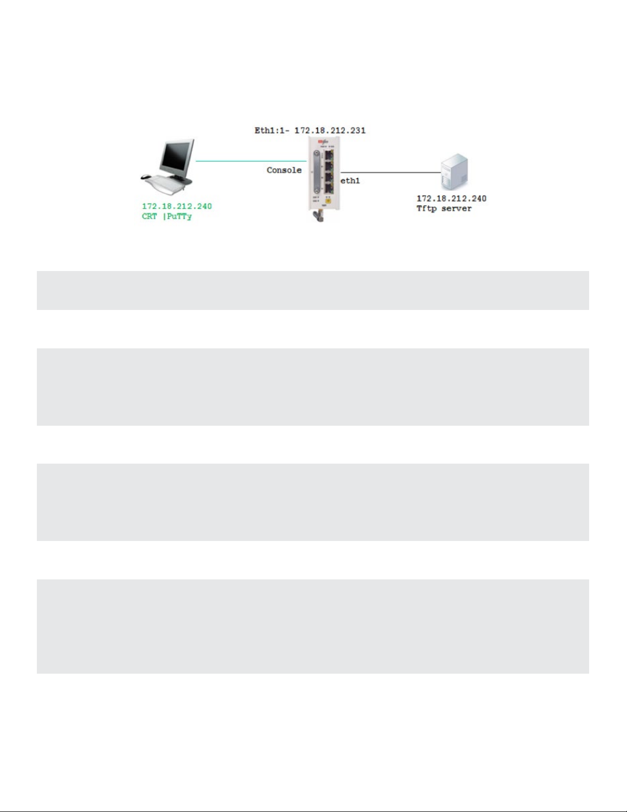
The following flow will show how to upgrade the OS image file and export the data base.
1. Connect your PC via serial console cable to the RL1000GW console port
2. Create an IP interface over eth1
RL1000GW#router interface create address-prefix 172.18.212.231/24 physical-interface eth1
purpose application-host
3. Check connectivity to the tftp server from which the software will be downloaded
PING 172.18.212.240 (172.18.212.240): 56 data bytes
64 bytes from 172.18.212.240: seq=0 ttl=64 time=1.026 ms
64 bytes from 172.18.212.240: seq=1 ttl=64 time=0.642 ms
64 bytes from 172.18.212.240: seq=2 ttl=64 time=0.647 ms
4. Display available OS files
RL1000GW# os-image show-list
Versions list:
R F _ R L10 0 0G W _ 4.0.02.57.ta r (ac tiv e)
R F _ R L10 0 0G W _ 4.0.02.56.t a r
5. Deleting unneeded OS files
RL1000GW# os-image delete version-name RF _ RL1000GW _ 4.0.02.56.tar
RL1000GW# os-image show-list
Versions list:
R F _ R L10 0 0G W _ 4.0.02.57.ta r (ac tiv e)
RL1000GW#
TECH SUPPORT: 1.888.678.9427
INS_RL1000GW_REV– 15 Jul 2016 PAGE 26
Page 27

INSTALLATION AND OPERATION MANUAL RL1000GW
6. downloading OS file from TFTP server
Co m m and syntax:
RL1000GW# os-image download download tftp://aa.bb.cc.dd/file _ name
Exa mple:
os-image download download-sw tftp://172.18.212.240/RF _ RL1000GW _ 4.0.02.67.tar
7. following download progress
RL1000GW#os-image download-status
In progress 3 MB
RL1000GW#os-image download-status
In progress 10 MB
RL1000GW#os-image download-status
In progress 16 MB
RL1000GW#os-image download-status
Finished Download
8. Activating desired OS file (will automatically reboot the device)
RL1000GW# os-image activate version-name RF _ RL1000GW _ 4.0.02.67.tar
..
RL1000GW# os-image show-list
Versions list:
R F _ R L10 0 0G W _ 4.0.02.57.ta r
R F _ R L10 0 0G W _ 4.0.02.67.ta r (a ct iv e)
9. Exporting configuration data base to TFTP server
Co m m and syntax:
RL1000GW# db export filename my-file-name remote-host aa.bb.cc.dd
Exa mple:
RL1000GW# db export filename db-May-14 remote-host 172.18.212.240
10. Importing configuration data base to TFTP server
Co m m and syntax:
RL1000GW# db import filename my-file-name remote-host aa.bb.cc.dd
Exa mple:
RL1000GW# db import filename db-May-14 remote-host 172.18.212.240
TECH SUPPORT: 1.888.678.9427
INS_RL1000GW_REV– 15 Jul 2016 PAGE 27
Page 28

INSTALLATION AND OPERATION MANUAL RL1000GW
Completed OK, reboot to activate
RL1000GW# reload schedule in 0
Safe Mode
The system has two safe mode menus available.
To access safe mode, connect to the router via console cable, reboot the unit and interrupt the
boot process at the safe mode prompt.
The first Safe mode is used for approved technician only and should not be used unless specified
by ComNet. This safe mode state is available at the prompt
“For first safe mode Press ‘s’...”
The second safe mode is accessible at the following prompt:
##########################
For safe mode Press ‘s’...
##########################
Below screenshot details the 2 safe mode menus and their options for:
1. system reset
2. Load the factory-default configuration for the device
3. Write to EEPROM (should be used only after consulting with ComNet)
4. Recover the device’s images from a package file
5. Export / Import DB (running configuration)
TECH SUPPORT: 1.888.678.9427
INS_RL1000GW_REV– 15 Jul 2016 PAGE 28
Page 29

INSTALLATION AND OPERATION MANUAL RL1000GW
Safe mode view
For first safe mode Press ‘s’...
PHY: fixed-0:02 - Link is Up - 100/Full
s
-----------------------------------------------------------------------------------------
|safe mode menu:
|
| reset | 1 : Reset the device
|
| format | 2 : Format flash
|
| activate | 3 : Activate sw version on flash
|
| install | 4 : Install first sw version from TFTP
|
| continue | c : Continue with start up process
|
| help | H : Display help about this utility
|
c
Extracting software
\s
OK
01/01/70 00:01:09 Running applications
##########################
For safe mode Press ‘s’...
##########################
-----------------------------------------------------------------------------------------
|safe mode menu:
| reset | 1 : Reset the device
| defcfg | 2 : Load the factory-default configuration for the device
| eeprom | 3 : Write to EEPROM
| recover | 4 : Recover the device’s images from a package file
| db | 5 : Export / Import DB
| continue | c : Continue in start up process
| help | H : Display help about this utility
TECH SUPPORT: 1.888.678.9427
INS_RL1000GW_REV– 15 Jul 2016 PAGE 29
Page 30

INSTALLATION AND OPERATION MANUAL RL1000GW
SW Image Installation
Following steps guides to software first installation.
1. Connect your PC via serial console cable to the RL1000GW console port
2. Rebott the unit and Enter safe mode. Select option 4
-----------------------------------------------------------------------------------------
|safe mode menu:
|
| reset | 1 : Reset the device
|
| format | 2 : Format flash
|
| activate | 3 : Activate sw version on flash
|
| install | 4 : Install first sw version from TFTP
|
| continue | c : Continue with start up process
|
| help | H : Display help about this utility
|
!!!!!!!!!!!!!!!!!!!!!!!!!!!!!!!!!!!!!!!!!!!!!!!!!!!!!!!!!!!!!!!!!!!!!!!!!!!!!!!!!!!!!!!!!
!!!!!!!!!!!!!!!!!!!!!!!!! T h i s c h o i c e w il l d e l e t e d at a fr o m f l a s h !!!!!!!!!!!!!!!!!!!!!!!
!!!!!!!!!!!!!!!!!!!!!!!!! C o n t i n u e [ y /n] !!!!!!!!!!!!!!!!!!!!!!!
!!!!!!!!!!!!!!!!!!!!!!!!!!!!!!!!!!!!!!!!!!!!!!!!!!!!!!!!!!!!!!!!!!!!!!!!!!!!!!!!!!!!!!!!!
y
3. Assign ip address and subnet to the RL1000GW
!!!!!!!!!!!!!!!!!!!!!!!!!!!!!!!!!!!!!!!!!!!!!!!!!!!!!!!!!!!!!!!!!!!!!!!!!!!!!!!!!!!
! Connect an ethernet cable to the ETH port and Enter the following parameters (xxx.xxx.
xxx.xxx) !
!!!!!!!!!!!!!!!!!!!!!!!!!!!!!!!!!!!!!!!!!!!!!!!!!!!!!!!!!!!!!!!!!!!!!!!!!!!!!!!!!!!
DEVICE IP ADDRESS [10.10.10.5]: [enter here an ip for the RL1000GW]
DEVICE IP ADDRESS NETMASK [255.255.255.0]: [enter here subnet ip for the RL1000GW]
TECH SUPPORT: 1.888.678.9427
INS_RL1000GW_REV– 15 Jul 2016 PAGE 30
Page 31

INSTALLATION AND OPERATION MANUAL RL1000GW
4. Choose the interface at which the telnet server is connected at
Select Interface (press 1 or 2)[1]:
1) ETH1 10/100 MB
2) ETH 2
1
5. Set the ip address of the tftp server holding the OS-Image file
TF TP SE R V ER IP A D D R ESS [10.10.10.10]: 10.10.10.6
6. Connect the RL1000GW at port ETH1 (RJ45) to your tftp server machine.
Verify ping availability between the two.
7. Enter the OS-image file name.
Enter version number on TFTP Server.
For main menu press X
R F _ R L10 0 0G W _ 4.0.02.5 2.ta r
8. OS-Image file will be downloaded and activated
01/01/70 00:03:18 downloading RF _ RL1000GW _ 4.0.02.52.tar from server 10.10.10.6 to /opt/
C o m N e t,t r y #1
============25%===========50%===========75%=75%===========100%Version Download Complete
OEM Ver RF _ RL1000GW
OEM NEW _ VERSION RF _ RL1000GW _ 4.0.02.52.tar
Detected OEM 3
Veryfing sw version RF _ RL1000GW _ 4.0.0252.tar
=a pp l.t a r.g z: OK
==vmlinux.UBoot: OK
SW version was verified successfully
vmlinux.tar
=vmlinux.UBoot: OK
Updating bank1 with vmlinux.UBoot file, please wait ...===OK
Version was installed and activated successfully
Reboot in 0=
TECH SUPPORT: 1.888.678.9427
INS_RL1000GW_REV– 15 Jul 2016 PAGE 31
Page 32

INSTALLATION AND OPERATION MANUAL RL1000GW
Ethernet Port Interfaces
Depending on the variant ordered, your RL1000GW hardware may include the following Ethernet
interfaces
Fastethernet, 10/100, copper RJ45. Included at all variants.
» Referred to in CLI as eth1.
Gigabitethernet, SFP SGMII. Optional ordering.
» SFP modules are not included.
» Copper and fiber SFP of 100/1000 types are supported.
» Referred to in CLI as eth2.
Commands Hierarchy
+ root
+ port
- set port { eth1| eth2} [admin-status {disabled |enabled}] [autoneg {on| off}] [duplex {half| full}
[speed {10| 100| 1000}]
+ show
- interface-table port-type port {eth1| eth2}
- rmon-etherstat-table port {eth1| eth2}
- status
+ sf-port
- ddm
- detailed
- extended
TECH SUPPORT: 1.888.678.9427
INS_RL1000GW_REV– 15 Jul 2016 PAGE 32
Page 33

INSTALLATION AND OPERATION MANUAL RL1000GW
Show example
RL1000GW# port show interface-table port eth1
Interface ETH1
+------------------------+--------+-------------------------+-------+
| Counter Name | Value | Counter Name | Value |
+========================+========+=========================+=======+
| In non-unicast packets | 2670 | Out non-unicast packets | 5 |
+------------------------+--------+-------------------------+-------+
| In unicast packets | 233 | Out unicast packets | 4 |
+------------------------+--------+-------------------------+-------+
| In errors packets | 0 | Out errors packets | 0 |
+------------------------+--------+-------------------------+-------+
| In octets | 311651 | Out octets | 690 |
+------------------------+--------+-------------------------+-------+
| Unknown packets | 0 | | |
+------------------------+--------+-------------------------+-------+
RL1000GW# port show status
+-----+------+------+--------------+------------------+-------+--------+
| idx | slot | port | admin Status | auto Negotiation | speed | duplex |
+=====+======+======+==============+==================+=======+========+
| 1 | 1 | eth1 | enabled | on | 100M | full |
+-----+------+------+--------------+------------------+-------+--------+
| 2 | 1 | eth2 | enabled | on | 100M | full |
+-----+------+------+--------------+------------------+-------+--------+
RL1000GW# port show rmon-etherstat-table port eth1
Interface ETH1
+---------------+--------+----------------+-------+
| Counter Name | Value | Counter Name | Value |
+===============+========+================+=======+
| total packets | 2789 | undersize | 0 |
+---------------+--------+----------------+-------+
| total octets | 300591 | oversize | 0 |
+---------------+--------+----------------+-------+
| broadcast | 1832 | Size 64 | 1055 |
+---------------+--------+----------------+-------+
TECH SUPPORT: 1.888.678.9427
INS_RL1000GW_REV– 15 Jul 2016 PAGE 33
Page 34

INSTALLATION AND OPERATION MANUAL RL1000GW
| multicast | 725 | Size 65-127 | 1239 |
+---------------+--------+----------------+-------+
| align error | 0 | Size 128-255 | 435 |
+---------------+--------+----------------+-------+
| dropped event | 0 | Size 256-511 | 35 |
+---------------+--------+----------------+-------+
| fragmented | 0 | Size 512-1023 | 4 |
+---------------+--------+----------------+-------+
| jabbers | 0 | Size 1024-1518 | 21 |
+---------------+--------+----------------+-------+
TECH SUPPORT: 1.888.678.9427
INS_RL1000GW_REV– 15 Jul 2016 PAGE 34
Page 35

INSTALLATION AND OPERATION MANUAL RL1000GW
Login and Management
Configuring the Login Authentication Method sets the authentication method for user logins.
Default user of the system:
» Name : su
» Password : 1234
» Privileges : all
» Available by: Console and Telnet.
Serial Console Port
Management over the serial console port is enabled by default.
NOTE: A console cable is supplied in the box. The cable is uniquely colored white.
Connecting to the Console Port
The console port is an EIA232 VT-100 compatible port to enable the definition of the device’s
basic operational parameters.
Connecting the device to a PC using the Console Port:
Connect the RJ-45 connector of the console cable to the device’s Console Port (CON).
Connect the other side of the cable to the PC.
Configure the PC port to 9600-N-8-1 (9600 bps, no parity,8 data bits, 1 stop bit, no flow control)
Below table details the console cable pin-out.
RJ45 Male DB9 Female
1 -
2 3
3 2
4 5
5 5
6 -
7 -
8 -
TECH SUPPORT: 1.888.678.9427
INS_RL1000GW_REV– 15 Jul 2016 PAGE 35
Page 36

INSTALLATION AND OPERATION MANUAL RL1000GW
CLI Terminal Commands
Following are commands related to the CLI terminal.
+ root
- idle-timeout
Management
The router can be managed via following methods:
» IP based.
» Serial console port.
Default state
Feature Default state
Layer 3 interface No default IP
SSH No available
Telnet Enabled
Console Enabled
User User name : su
Password : 1234
Privilege : all
DHCP Client disabled
TECH SUPPORT: 1.888.678.9427
INS_RL1000GW_REV– 15 Jul 2016 PAGE 36
Page 37

INSTALLATION AND OPERATION MANUAL RL1000GW
Commands Hierarchy
+ root
+ reload
- schedule date-and-time YYYY-MM-DD,HH:MM:SS
- schedule every <180 – 604800 seconds >
- schedule time HH:MM:SS
- schedule in <0 – 604800 seconds >
- cancel
- show
+ users
- modify username su password <password>
- show
- commit
- delete diagnostics
- delete logs
- delete startup-cfg
- show disk info
- router interface show
- ping <destination>
- ssh {<user>@<remote IP>}
- telnet [user]@{remote IP}
TECH SUPPORT: 1.888.678.9427
INS_RL1000GW_REV– 15 Jul 2016 PAGE 37
Page 38

INSTALLATION AND OPERATION MANUAL RL1000GW
Commands Description
Command Description
reload schedule date-and-time Set specific date and time for router reload.
Time format: YYYY-MM-DD,HH:MM:SS
configuration which was not committed will not be available after reload!
reload schedule every Set time interval for cyclic automatic system reload.
Permissible range in seconds is 180 – 604800.
Configuration which was not committed will not be available after reload!
reload schedule time Set specific time for router reload.
Time format: HH:MM:SS
configuration which was not committed will not be available after reload!
reload schedule in Set specific timer for next router reload.
Permissible range in seconds is 180 – 604800.
Configuration which was not committed will not be available after reload!
reload cancel Cancels all scheduled automatic reloads
reload show Shows user set scheduled reloads
Users password: alpha-numeric string. Mandatory to consist of minimum one Capital letter, one
small letter, one special symbol, one number.
Changing password is permitted to the default user ‘su’ only. Once changed from the
default password 1234, returning to password 1234 is only possible by clearing the router
to its manufacturing defaults from safe mode.
TECH SUPPORT: 1.888.678.9427
INS_RL1000GW_REV– 15 Jul 2016 PAGE 38
Page 39

INSTALLATION AND OPERATION MANUAL RL1000GW
IP Interfaces
The RL1000GW supports multiple layer 3 interfaces to be set for the purposes of:
» Routing.
» Management.
» Serial services.
IP Interfaces
The following services require assignment of an IP interface.
» DHCP client
» Management
» Ping
» Trac e route
» OSPF
» RIPv2
» Tftp client
» Serial tunneling
» Terminal server
» Protocol gateway
» L2-VPN
» L3-DMVPN
» IPSec
Interface Assignment Rules
» An IP interface may optionally be set with a VLAN tag to result on vlan tagging at the interface
egress.
» The VLAN tag set to an interface must be unique.
» If a vlan tag is not set, packets will carry no vlan tag when egress the interface.
» An interface ID is automatically assigned to each IP interface.
» Each interface must be associated with a “purpose”.
› One (and only one) of the interfaces must be set to purpose ‘application-host’
› All other interfaces must be set to purpose ‘general’
› If a “purpose” is not configured by the user, the interface will receive the ‘general’ status.
TECH SUPPORT: 1.888.678.9427
INS_RL1000GW_REV– 15 Jul 2016 PAGE 39
Page 40

INSTALLATION AND OPERATION MANUAL RL1000GW
» Each interface must be in a unique subnet.
» Each interface must be associated to a physical interface. Either eth1 or eth2.
An interface cannot be associated with both.
» Physical interfaces (eth1, eth2) may be associated with more than one IP interface. Tagged
packets accessing the port will be routable to a relevant vlan IP interface. Untagged packets
accessing the port will be routable with IP interface set to be in the same subnet as the packets
origin (if such is available at the RL1000GW).
» IP interfaces associated to vlans are given an automatic name indicating the vlan tag they are
created with. The name format is:
eth<1|2>.<vlan id>
» IP interfaces not associated to a vlan, are given an automatic name indicating the id they are
created with. The name format is:
eth<1|2>:<id>
» Below is an example of interfaces configured with either vlan tag or id tag.
[/]router interface show
+----+------+---------+-------------------+------+------------------+--------------+----------
---+
| Id | VLAN | Name | IP/Subnet | Mtu | Purpose | Admin status |
Description |
+====+======+=========+===================+======+==================+==============+====
=========+
| 1 | N/A | eth1:1 | 172.17.203.100/24 | 1500 | application host | enable |
|
+----+------+---------+-------------------+------+------------------+--------------+----------
---+
| 2 | 20 | eth2.20 | 172.18.212.200/24 | 1500 | general | enable |
|
+----+------+---------+-------------------+------+------------------+--------------+----------
---+
[/]
TECH SUPPORT: 1.888.678.9427
INS_RL1000GW_REV– 15 Jul 2016 PAGE 40
Page 41

INSTALLATION AND OPERATION MANUAL RL1000GW
IP interface id
When an IP interface is created without explicitly assigned vlan tag, it will not support vlan
tagging. Packet coming inward to the physical interface (eth1 or eth2 as assigned) which are
holding a vlan tag will not be received by the IP interface.
Packets originated from the IP interface (egress) will be without vlan tag.
NOTE: Use id assignment to an IP interface when the network does not support vlan tagging and
ingress packets to the physical interface are untagged.
IP interface VLAN id
When an IP interface is assigned with a VLAN id it supports vlan tagging. Packet coming inward to
the physical interface (eth1 or eth2 as assigned) will be received by the IP interface only if holding
the required VLAN tag.
Packets originated from the IP interface will be without vlan tag.
NOTE: Use VLAN assignment to an IP interface when the network supports vlan tagging and a
service segregation is required.
IP Interface Commands Hierarchy
+ root
+ router
- interface {create | remove} address-prefix <IP address>/<netmask> [vlan <vlan id>]
purpose {application-host |general} physical-interface [eth1 |eth2] [description <>] [mtu
<1500,(128-154 4)>]
+ static
- enable
- dissable
- show running-cofig
- exit
+ configure terminal
- [no] ip route static <dest network> /<subnet> <Gateway>
- write memory
TECH SUPPORT: 1.888.678.9427
INS_RL1000GW_REV– 15 Jul 2016 PAGE 41
Page 42

INSTALLATION AND OPERATION MANUAL RL1000GW
- exit
+ dhcp {enable | dissable |show}
- enable physical-interface {eth1| eth2}
- disable physical-interface {eth1| eth2}
- show physical-interface {eth1| eth2}
- interface show
- route show
IP Interface Commands Description
Command Description
Router Enter the router configuration mode
interface
create | remove Add or Remove an IP interface. The configuration should include:
Address-prefix : IP address in the format aa.bb.cc.dd/xx
VLAN: vlan ID for egress packets from the interface
Purpose: application-host or general.
physical-interface: association to the relevant Ethernet port [eth1 |eth2]
mtu: set size in bytes. Default is 1500
description: descriptive text
Static Access the router static mode.
Enable: enable configuration
Disable: disable configuration
Exit: exit to upper level
show running-cofig: static route config
configure terminal
[no] ip route static dest network: a.b.c.d
subnet: 0-32
gateway: a.b.c.d
Show Show application engine IP interfaces
TECH SUPPORT: 1.888.678.9427
INS_RL1000GW_REV– 15 Jul 2016 PAGE 42
Page 43

INSTALLATION AND OPERATION MANUAL RL1000GW
Example
1. Create an IP interface with vlan 1 and static route (default gateway).
RL1000GW#
router interface create address-prefix 10.10.10.100/24 vlan 5 purpose application-host
physical-interface eth1
co m m it
co m m it ok
router interface show
+----+------+--------+-------------------+------+------------------+--------------+-----------
--+
| Id | VLAN | Name | IP/Subnet | Mtu | Purpose | Admin status |
Description |
+====+======+========+===================+======+==================+==============+=====
========+
| 1 | 5 | eth1.5 | 10.10.10.100/24 | 1500 | application host | enable |
|
+----+------+--------+-------------------+------+------------------+--------------+-----------
--+
[router/] static
router/static> enable
router/static# configure terminal
router/static(config)# ip route 0.0.0.0/0 172.17.212.100
router/static(config)# write
router/static(config)# exit
router/static# exit
co m m it
router route show
Kernel IP routing table
Destination Gateway Genmask Flags Metric Ref Use Iface
172.17.212.0 0.0.0.0 255.255.255.0 U 0 0 0 eth1.100
0.0.0.0 172.17.212.100 0.0.0.0 UG 0 0 0 eth1.100
Completed OK
TECH SUPPORT: 1.888.678.9427
INS_RL1000GW_REV– 15 Jul 2016 PAGE 43
Page 44

INSTALLATION AND OPERATION MANUAL RL1000GW
2. Create an IP interface without vlan id
RL1000GW#
RL1000GW#router interface create address-prefix 172.17.203.100/24 physical-interface eth2
purpose application-host
co m m it
co m m it ok
RL1000GW#router interface show
+----+------+--------+-------------------+------+------------------+--------------+-----------
--+
| Id | VLAN | Name | IP/Subnet | Mtu | Purpose | Admin status |
Description |
+====+======+========+===================+======+==================+==============+=====
========+
| 1 | N/A | eth2:1 | 172.17.203.100/24 | 1500 | application host | enable |
|
+----+------+--------+-------------------+------+------------------+--------------+-----------
--+
TECH SUPPORT: 1.888.678.9427
INS_RL1000GW_REV– 15 Jul 2016 PAGE 44
Page 45

INSTALLATION AND OPERATION MANUAL RL1000GW
Example
1. Enable dhcp on interface eth1 to retrieve an IP from a dhcp server
RL1000GW#
[/]router dhcp enable physical-interface eth1
[/]router interface show
+------+------+-----+-----------+---------+-------------+
| VLAN | Name | Id | IP/Subnet | Purpose | Description |
+======+======+=====+===========+=========+=============+
| N/A | eth1 | N/A | N/A | N/A | DHCP |
+------+------+-----+-----------+---------+-------------+
[/]
[/]router interface show
+------+------+-----+-------------------+---------+-------------+
| VLAN | Name | Id | IP/Subnet | Purpose | Description |
+======+======+=====+===================+=========+=============+
| N/A | eth1 | N/A | 172.18.212.242/28 | N/A | DHCP |
+------+------+-----+-------------------+---------+-------------+
TECH SUPPORT: 1.888.678.9427
INS_RL1000GW_REV– 15 Jul 2016 PAGE 45
Page 46

INSTALLATION AND OPERATION MANUAL RL1000GW
Diagnostic
System logs export
The system logs can be exported to the flash drive as a time conditioned task.
Commands Hierarchy
+ Root
+ schedule
- add task-name copy-logs [day |hour |minute |month |year]
- remove task-name copy-logs
- show
Commands Description
Command Description
Schedule manage scheduled task to copy system logs to the usb drive. To mound a usb drive insert it
to the router usb port and reboot the router.
add task-name copy-logs Add a scheduled task to copy system logs to the usb drive.
Day : <1-31>
Month : <1-12>
year : <2013 -3000>
hour : <1-24>
minute : <1-60>
remove task-name copy-logs Remove a scheduled task to copy system logs to the usb drive.
Show Display tasks
TECH SUPPORT: 1.888.678.9427
INS_RL1000GW_REV– 15 Jul 2016 PAGE 46
Page 47

INSTALLATION AND OPERATION MANUAL RL1000GW
Capture Ethernet service traffic
The system supports sniffing and capturing of Ethernet traffic for selected service IP interfaces.
This capability is important in order to diagnose network traffic of a service for debugging.
The capturing is available for IP interfaces set at the ACE.
Captures can be displayed at the terminal or exported to a user tftp server.
Commands Hierarchy
+ root
+ capture
- start –i {eth1.<vlan id> | eth1:<id>} [-C] [-s] [-y] [expression <>]
- stop
- delete
- export remote-address <destination address,A.B.C.D>
- show {captured-packets –c <number>| status}
- help
Commands Description
Command Description
Capture Start: initiate Ethernet traffic capture on a selected ACE IP interface.
-i: mandatory prefix to be followed with the IP interface name eth1.<vlan id> where “vlan id” is the vlan
of the ip interface.
Stop : stop Ethernet traffic capture
Delete : delete capture files
Export remote-address: export file to a tftp server.
Show captured-packets –C<1-200>: display the captured content up to a chosen length (1-200) lines.
Show status : display capture configuration
Help: display help on settings options.
Example
1. Set an ip interface in the ACE for the vlan
router interface create address-prefix 172.18.212.232/24 vlan 1 purpose application-host
physical-interface eth2
co m m it
co m m it ok
TECH SUPPORT: 1.888.678.9427
INS_RL1000GW_REV– 15 Jul 2016 PAGE 47
Page 48

INSTALLATION AND OPERATION MANUAL RL1000GW
router interface show
+------+--------+-----+-----------------+------------------+-------------+
| VLAN | Name | Id | IP/Subnet | Purpose | Description |
+======+========+=====+=================+==================+=============+
| 1 | eth2.1 | N/A | 172.18.212.232/24 | application host | |
+------+--------+-----+-----------------+------------------+-------------+
2. Start capture
Capture start –i eth2.1
Capture show
[capture/] show status
capture is running
3. Stop the capture and display the output
Capture stop
capture show captured-packets -c 10
16:55:07.370814 IP 172.18.212.240.netbios-ns > 172.18.212.232.netbios-ns: NBT UDP PACKET(137):
QUERY; POSITIVE; RESPONSE; UNICAST
16:55:07.616319 IP 172.18.212.240.17500 > 255.255.255.255.17500: UDP, length 112
16:55:07.616628 IP 172.18.212.240.17500 > 172.18.212.255.17500: UDP, length 112
16:55:07.926503 arp who-has 172.18.212.232 tell 172.18.212.64
16:55:08.122046 IP 172.18.212.240.netbios-ns > 172.18.212.232.netbios-ns: NBT UDP PACKET(137):
QUERY; POSITIVE; RESPONSE; UNICAST
16:55:08.258801 arp who-has 172.18.212.232 tell 172.18.212.40
16:55:08.602306 IP 172.18.212.40.17500 > 255.255.255.255.17500: UDP, length 112
16:55:08.604927 IP 172.18.212.40.17500 > 255.255.255.255.17500: UDP, length 112
16:55:08.605016 IP 172.18.212.40.17500 > 172.18.212.255.17500: UDP, length 112
16:55:08.680664 CDPv2, ttl: 180s, Device-ID ‘Router’[|cdp]
TECH SUPPORT: 1.888.678.9427
INS_RL1000GW_REV– 15 Jul 2016 PAGE 48
Page 49

INSTALLATION AND OPERATION MANUAL RL1000GW
Syslog
Syslog is a protocol used for capturing log information for devices on a network. The syslog
protocol provides a transport to allow a machine to send event notification messages across
IP networks to event message collectors, also known as syslog servers. The protocol is simply
designed to transport the event messages.
One of the fundamental tenets of the syslog protocol and process is its simplicity. The
transmission of syslog messages may be started on a device without a receiver being configured,
or even actually physically present.
This simplicity has greatly aided the acceptance and deployment of syslog.
User enables syslog server and configures the syslog related parameters. The logging process
controls the distribution of logging messages to the various destinations, such as the local buffer
or syslog server.
Severity of logging can be set with its name tag.
The syslog works in UDP mode, default port 514.
The default state of the syslog is enabled, destination ‘local’.
TECH SUPPORT: 1.888.678.9427
INS_RL1000GW_REV– 15 Jul 2016 PAGE 49
Page 50

INSTALLATION AND OPERATION MANUAL RL1000GW
The Priority indicator
The Priority indicator is calculated as:
Priority = 8x facility_coefficient + severity_level.
facility coefficient facility Priority
0 kernel messages 0x8 + level
1 user-level messages 1x8 + level
2 mail system 2x8 + level
3 system daemons 3x8 + level
4 security/authorization messages 4x8 + level
5 messages generated internally by syslog 5x8 + level
6 line printer subsystem 6x8 + level
7 network news subsystem 7x8 + level
8 UUCP subsystem 8x8 + level
9 clock daemon 9x8 + level
10 security/authorization messages 10x8 + level
11 FTP daemon 11x8 + level
12 NTP subsystem 12x8 + level
13 log audit 13x8 + level
14 log alert 14x8 + level
15 clock daemon (note 2 15x8 + level
16 Local0 16x8 + level
17 Local1 17x8 + level
18 Local2 18x8 + level
19 Local3 19x8 + level
20 Local4 20x8 + level
21 Local5 21x8 + level
22 Local6 22x8 + level
23 Local7 23x8 + level
TECH SUPPORT: 1.888.678.9427
INS_RL1000GW_REV– 15 Jul 2016 PAGE 50
Page 51

INSTALLATION AND OPERATION MANUAL RL1000GW
Example, Syslog message priority tag with facility local0
Level purpose Numeric level Priority (w. local0)
emergencies 0 16x8+0 =12 8
alerts 1 129
critical 2 130
errors 3 131
warnings 4 132
notification 5 133
informational 6 134
debugging 7 135
Message Format
The following will describe the structure of syslog messages.
Message severity
Severity S indicaror Description
0 S=E Emergency: system is unusable
1 S=A Alert: action must be taken immediately
2 S=C Critical: critical conditions
3 S=E Error: error conditions
4 S=W Warning: warning conditions
5 S=N Notice: normal but significant condition
6 S=I Informational: informational messages
7 S=D Debug: debug-level messages
TECH SUPPORT: 1.888.678.9427
INS_RL1000GW_REV– 15 Jul 2016 PAGE 51
Page 52

INSTALLATION AND OPERATION MANUAL RL1000GW
Firewall TCP SCADA Protocols
The following will describe the ComNet structure of syslog messages generated for firewall of IEC
104, DNP3 TCP, MODBUS TCP.
Console message format
The message format when sent to the CLI console is as follow,
{[APP-NAME] [PROCID][Severity] [MSGID] [Time Stamp]} {[MSG]} {STRUCTURED-DATA}
The message structured data includes following information fields,
|S=SEVERITY|SG=VLAN _ ID|SRC=SRC _ IP _ ADDR:SRC _ IP _ PORT|DST=DEST _ IP _ ADDR:DEST _ IP _
PORT|LEN=DATA _ MSG _ LEN|TTL=TTL|PROTO=PRTOCOL _ NA ME|MSG=VIOLATION _ DESCR|
Examples of messages received at the CLI
(Use the command “firewall log show” at the ACE to retrieve following log entries.)
1. Example for violation type “no rule configured”
- RF _ Syslog : module 3 (firewall) severity 3 message : firewall
- |ID =74|T=2014- 05 -12,11:52:43
|S= E|SG =3500|SR C =172.18.212.50:52011|DST=172.18.212.46:2404|LEN =56|TT L =128|PRO T O=iec104|MSG =[0x 100]
[45,0]:FW RULE - no rule configured| (164 bytes)
2. Example for violation type “protocol type mismatch”
- RF _ Syslog : module 3 (firewall) severity 1 message : firewall
- |ID =80|T =2014-05-1 2,11:52:59
|S= A|SG =3500|SRC=172.18.212.50:52011|DST =172.18.212.46:2404|LE N=56|TT L=128|PR O TO =ie c 104|M S G =[0x101]
[45,0]:FW PROTOCOL protcol type missmatch| (170 bytes)
Server message format
The message format when sent to a SYSLOG server is,
{<PRI> [Host IP] [Time Stamp] [APP-NAME]} {MSG} {STRUCTURED-DATA}
The message structured data includes following information fields,
|S=SEVERITY|SG=VLAN _ ID|SRC=SRC _ IP _ ADDR:SRC _ IP _ PORT|DST=DEST _ IP _ ADDR:DEST _ IP _
PORT|LEN=DATA _ MSG _ LEN|TTL=TTL|PROTO=PRTOCOL _ NA ME|MSG=VIOLATION _ DESCR|
Examples of messages received at a server
TECH SUPPORT: 1.888.678.9427
INS_RL1000GW_REV– 15 Jul 2016 PAGE 52
Page 53

INSTALLATION AND OPERATION MANUAL RL1000GW
1. Example for violation type “no rule configured”
- Local0.Error 172.18.212.183 May 12 11:52:54 SW RLGE2FE16R firewall
- |ID =79|T =2014-05 -1 2,11:52:54
|S= E|SG =3500|SR C =172.18.212.50:52011|DST=172.18.212.46:2404|LEN = 62|TTL=128|PROT O =iec104|MSG =[0 x 100]
[45,0]:FW RULE - no rule configured|
2. Example for violation type “protocol type mismatch”
- 05-12-2014 16:53:40 Local0.Alert 172.18.212.183 May 12 11:52:59 SW RLGE2FE16R firewall
- |ID =80|T =2014-05-1 2,11:52:59
|S= A|SG =3500|SRC=172.18.212.50:52011|DST =172.18.212.46:2404|LE N=56|TT L=128|PR O TO =ie c 104|M S G =[0x101]
[45,0]:FW PROTOCOL protcol type missmatch| (170 bytes)
Firewall Serial SCADA Protocols
The following will describe the ComNet structure of syslog mssages generated for firewall of IEC
101, DNP3 RTU, MODBUS RTU.
IP=IP _ ADDR|SLOT=SLOT _ NUMBER|PORT=PORT _ NUMBER|DIR=DATA _ MSG _ DIR|LEN=DATA _ MSG _
LEN|PROTO=PROTOCOL _ NA ME|MSG=VIOLATION _ DESCR|
TECH SUPPORT: 1.888.678.9427
INS_RL1000GW_REV– 15 Jul 2016 PAGE 53
Page 54

INSTALLATION AND OPERATION MANUAL RL1000GW
Message fields description
The following will further describe the syslog message fields
Command Description
VLAN_ID The VLAN number
SRC_IP_ADDR The pointed string source IP address.
SRC _I P_P O RT The source IP port number
DEST_IP_ADDR The pointed string destination IP address.
DES T_ IP_ POR T The destination IP port number
DATA _MSG_ LEN The total data message length
TTL| The ttl value of the IP header
PRTOCOL_NAME The protocol name field. The following values are available:
“any”
“icmp”
“tcp”
“udp”
“ipencap”
“gre”
“modbus_tcp”
“modbus_rtu”
“iec10 4”
“iec101”
“dnp3”
VIOLATION_DESCR The FW violation description string. The following format is used:
[Major Protocol Id,Minor Protocol Id]:Violation description string
Major Protocol Id: Major protocol id value,
for ModBus – Function Code
for IEC101/104 - Type Id
for DNP3 - Function Code
Minor Protocol Id: Minor protocol id value,
for ModBus – Sub-Function Code
for IEC101/104 - non used
for DNP3 - non used
Violation description string:
The following values are available for general violations:
“Flow is not allowed”
“FW PROTOCOL no violation”
“FW internal error (no drop)”
“FW PROTOCOL SW problem”
“FW PROTOCOL no free memory”
“FW PROTOCOL illegal message length”
“FW PROTOCOL illegal data length”
“FW PROTOCOL illegal value”,
“FW PROTOCOL Timeout problem”
“FW PROTOCOL message flow inconsistancy”
“FW PROTOCOL invalid creation”
“FW PROTOCOL general flow error”
“FW PROTOCOL illeagl message”
“FW PROTOCOL general session problem”
“FW PROTOCOL illegal identifier”
“FW PROTOCOL illegal address”
“FW PROTOCOL protcol type missmatch”
“FW RULE - illegal flow”
“FW RULE - illegal message”
“FW RULE - illegal identifier”
“FW RULE - illegal address”
“FW RULE - no rule configured”
TECH SUPPORT: 1.888.678.9427
INS_RL1000GW_REV– 15 Jul 2016 PAGE 54
Page 55

INSTALLATION AND OPERATION MANUAL RL1000GW
Command Description
VIOLATION_DESCR The following values are available for MODBUS protocol violations:
“Modbus validity: illegal function”
“Modbus validity: illegal sub-function”
“Modbus validity: illegal encapsulated interface”
“Modbus validity: unknown device ID”
“Modbus validity: illegal quantity “
“Modbus validity: illegal FIFO byte counter”
“Modbus validity: illegal FIFO counter”
“Modbus validity: illegal record number”
“Modbus validity: illegal reference type”
“Modbus validity: illegal byte counter”
“Modbus validity: illegal length of File sub-record”
“Modbus validity: illegal write quantity”,
“Modbus validity: illegal read quantity”
“Modbus validity: illegal File sub-record length”
“Rule violation: not allowed function”
“Rule violation: not allowed sub function”
“Rule violation: out of allowed address range”
“Rule violation: not allowed quantity”
“Rule violation: out of allowed value range”
“Rule violation: not allowed sub function”
“Rule violation: not allowed file number”
“Rule violation: not allowed record number”
“Rule violation: out of allowed READ address range”
“Rule violation: out of allowed WRITE address range”
“Rule violation: not allowed READ quantity”
“Rule violation: not allowed WRITE quantity”
“Rule violation: out of the allowed address range”
“Rule violation: out of the allowed FIFO addresse range”
“Rule violation: out of the allowed encapsulated interface range”
“Rule violation: out of the allowed devise identifiers range”
“Rule violation: out of the allowed object identifiers range”
“Rule violation: address and quantity are out of the allowed range”
“Rule violation: illegal operation”
“Rule violation: inconsistent TCP Unit Identifier”
The following values are available for IEC104/IEC101 protocol violations:
“Iec104 validity: Illegal TypeId field”
“Iec104 validity: Illegal Cause field”
“Iec104 validity: Illegal APCI header”
“Iec104 validity: Illegal Control field 1 in APCI header”
“Iec104 validity: Illegal Control field 2 in APCI header”
“Iec104 validity: Illegal Control field 3 in APCI header”
“Iec104 validity: Illegal Control field 4 in APCI header”
“Iec104 rule validity: Illegal type id, no rule”
The following values are available for DNP3 protocol violations:
“DNP3 validity: Illegal Function Code field”
“DNP3 validity: Illegal Group Id field”
“DNP3 validity: Invalid Object”
“DNP3 validity: Parsing Error”
“DNP3 validity: unused”
“DNP3 validity: unused”
“DNP3 validity: unused”
“DNP3 validity: unused”
“DNP3 validity: MAX”
SLOT_NUMBER Serial Slot number on ComNet equipment
PORT_NUMBER Serial port number on ComNet equipment
DATA _MSG_ DIR The field defines data message direction. The following values are available:
“access”,
“net w o r k ”,
“N /A”
TECH SUPPORT: 1.888.678.9427
INS_RL1000GW_REV– 15 Jul 2016 PAGE 55
Page 56

INSTALLATION AND OPERATION MANUAL RL1000GW
DM-VPN logs
The following will describe the DM-VPN logs.
Message fields description
The following will further describe the syslog message fields
Ssylg message Description
“NHRP Event:<NHS-UP|NHS-DOWN>,i/f=<MGRE IF
NAME>,NHS=<address>”
“<MGRE IF NAME>,<ip/mask>,<NBMA NAME>: state change
<UP|DOWN> -> <UP|DOWN>”
“Handle interface UP, walk over upper layer device via
<ppp0>,Operator:<Mobile Operator>”
“Handle interface DOWN, walk over upper layer devices via
%s”
“WTR expired for <ip/mask>,<MGRE IF NAME>” Wait to restore timer expired. Relevant when protection group
“WTR started for <MGRE IF NAME> <ip/mask>,<NBMA
address> “
“WTR stopped for <MGRE IF NAME> <ip/mask>,<NBMA
address> “
“Failed to create dm-vpn mGRE interface <MGRE IF NAME>” Unexpected error while creating mGRE interface.
“Failed to reload config with <Mobile operator>” Unexpected error trying to change configuration.
“Failed to create ipsec tunnel <IPSEC tunnel name>” Failed to create ipsec tunnel
Failed to remove dm-vpn mGRE interface <MGRE IF NAME>” Failed to remove dm-vpn mGRE interface
“Failed to remove ipsec-vpn tunnel <IPSEC tunnel name>” Failed to remove ipsec-vpn tunnel
Appears when NHS status changed in spoke, happen when
registered to NHS (NHS-UP) or NHS became unreachable
(NHS-DOWN).
Appears when status of mgre interface changed.
Appears when cellular interface connected to mobile network
Appears when cellular interface disconnected from mobile
network
is configured between dm vpn interfaces
Relevant when protection group is configured between dm
vpn interfaces
Relevant when protection group is configured between dm
vpn interfaces
Cellular logs
The following will describe the Cellular logs.
Message fields description
The following will further describe the syslog message fields
Syslog message Description
“admin status <UP|DOWN>” Cellular enabled/disabled
“Modem is busy or no ready SIM, retrying...” Modem is not responsive or SIM cards are not present
“Cellular Admin UP cannot be applied, SIMs are disabled. Stop
operation”
“No ready SIMs” A SIM is enabled, but not in READY state
“Only SIM in slot <1|2> is ready” Only SIM in slot <1|2> is ready
“slot <1|2> is preferred” slot <1|2> is selected as preferred
“<1|2> slot has better(or equal) RSSI (<RSSI>>=<RSSI>).
Threshold is <Threshold>”
TECH SUPPORT: 1.888.678.9427
SIMs are not configured.
INS_RL1000GW_REV– 15 Jul 2016 PAGE 56
Page 57

INSTALLATION AND OPERATION MANUAL RL1000GW
Syslog message Description
“Both slots are below required threshold <RSSI>,<RSSI>
(threshold=<Threshold>)”
“<1|2> slot is above threshold as required <RSSI>>=<RSSI>.
Other slot <RSSI>”
“disconnected... attempt moving to alternative provider will be
performed”
“disconnected... attempt to recover will be performed” Announced disconnection while other provider is not
“failed to connect... attempt to recover will be performed” Announced failure while trying to connect
“T2 expired - remove caveat on slot <1|2>” Announce of T2 timer expiration
“T1 expired on slot <1|2>” Announce of T1 timer expiration
“Wait to restore expired. Attempt to move to primary...” Wait to restore expired. Attempt to move to primary SIM
“Wait to restore expired, but primary SIM is not present or
disabled”
“RSSI is <RSSI> - below required threshold (<Threshold>)” RSSI is <RSSI> - below required threshold
“RSSI is <RSSI> - below required threshold (<Threshold>), but
primary SIM is not present or disabled”
“Continiuty check failed, attempt moving to alternative
provider will be performed “
“Continiuty check failed, attempt to recover will be performed” Announce cont. check failure when no alternative provider is
“unexpected failure, keep trying.... Retry within <SEC> sec” Announce unexpected failure
“Clear caveat on slot <1|2>” Announce clear caveat of specified slot
“Retry threshold exceeded <RETRIES>, reloading switch!” Announce threshold exceeded of cellular failures while trying
“<ppp0> connected to <Operator>,IP <address>,
BAND=<WCDMA|GSM>, Channel=<channel>”
“Periodic echo check failed <NAME> LOSS=<%L
OSS>(threshold=<%THRESHOLD>), RTT=<Round
Trip>(threshold=<THRESHOLD>)”
“change SIM slot to <1|2>” SIM change
“SIM[<1|2>] state chg: <UNKNOWN|DISABLED|NOT_
PRESENT|PIN_LOCK|PUK_LOCK|READY|CONNECTING|FAILED
|CONNECTED|CONNECTED-AS-ALTERNATIVE|CONNECTEDAS-SECONDARY> ->
<UNKNOWN|DISABLED|NOT_PRESENT|PIN_LOCK|PUK_LOC
K|READY|CONNECTING|FAILED|CONNECTED|CONNECTEDAS-ALTERNATIVE|CONNECTED-AS-SECONDARY>”
“Cellular experienced <NUM1> backpressure events in last
<NUM2> seconds.Total since connected <NUM3>: <NUM4>”
Both slots are below required threshold
“<1|2> slot is above threshold as required
Announced disconnection while other provider is configured
configured
Wait to restore expired, but primary SIM is not present or
disabled
RSSI is <RSSI> - below required threshold (<Threshold>), but
primary SIM is not present or disabled
Announce cont. check failure when alternative provider is
configured
configured
to connect
Cellular connection information
Echo test failure
SIM state change
This log is to help to fine tune the rate limit for cellular
interface (Relevant when QOS is enabled)
TECH SUPPORT: 1.888.678.9427
INS_RL1000GW_REV– 15 Jul 2016 PAGE 57
Page 58

INSTALLATION AND OPERATION MANUAL RL1000GW
Serial Services logs
The following will describe the serial services logs.
<STRING from the module>
“connection with remote IP(<address>) for serial service id <SVC> is now resumed!!”
“no connection with remote IP(<address>) for serial service id <SVC>”
“no more missing data on Serial service id # <SVC>”
“Missing data on Serial service id # <SVC>”
“Serial Card on slot (<Slot>) is Active”
“Serial Card on slot (<Slot>) failure! Last seen <SEC>”
“Serial Station[<SLOT>,<PORT>]: Traffic is now resumed. Time=<TIME>, service-id <SVC>”
“Serial Point[<SLOT>,<PORT>,<SVC>]: No traffic since <TIME> (latest Rx=<NUM>)”
Scheduled Reload logs
The following will describe the scheduled reload logs.
Ssylog message
“Reload will happen every <SEC> seconds”
“Scheduled reload at <TIME> (within <SEC> seconds),daily=<TIME>”
“Next reload in <SEC> seconds”
“Scheduled reloading happens now!”
Commands Hierarchy
+ root
+ syslog
- level severity { emergencies | alerts | critical | errors | warnings | notification | informational
|debugging}
- remote {remote-address <a.b.c.d>} [remote-port (514,<514-9999>)]
- local
- show
-..
TECH SUPPORT: 1.888.678.9427
INS_RL1000GW_REV– 15 Jul 2016 PAGE 58
Page 59

INSTALLATION AND OPERATION MANUAL RL1000GW
Output example
A typical output of syslog at console interface
May 18 19:27:48 SmartSwitch user.warn kernel: Speed 100 Duplex 1 pause 0
May 18 19:27:48 SmartSwitch user.warn kernel: adjust _ link Addr 1 link 0 speed 100 o 100
dup 1 o 1
May 18 19:27:48 SmartSwitch user.info kernel: PHY: mdio@ff724000:01 - Link is Down
May 18 19:27:50 SmartSwitch user.warn kernel: adjust _ link Addr 1 link 1 speed 100 o 0 dup
1 o -1
May 18 19:27:50 SmartSwitch user.info kernel: PHY: mdio@ff724000:01 - Link is Up - 100/Full
TECH SUPPORT: 1.888.678.9427
INS_RL1000GW_REV– 15 Jul 2016 PAGE 59
Page 60

INSTALLATION AND OPERATION MANUAL RL1000GW
Discrete IO Channels
Discrete signals are very common in industrial applications to monitor alarms and indications from
the field side.
Monitoring the state of discrete input channels is supported by the RL1000GW.
NOTE: Software support for the DI channels will be available from R5.0
Interfaces
Connection terminal are as shown in below figure.
Diagnostics and logic states
1. Within the CLI diagnostics of the discrete channels can be viewed using the show command
RL1000GW # discrete show
2. Status of digital input is either high or low.
a. Default: low.
3. Status of digital output is either open or closed.
a. Default – open.
TECH SUPPORT: 1.888.678.9427
INS_RL1000GW_REV– 15 Jul 2016 PAGE 60
Page 61

INSTALLATION AND OPERATION MANUAL RL1000GW
Technical data
At digital Inputs please connect a DC source in the range 12vDC at terminals 6,4 for channel 1 or
5,4 for channel 2.
Digital outputs are dry mechanical relay contacts. Maximum power to be implemented at the
contacts :
AC: Max 250v, 37.5vA.
DC: Max 220v,30 watt.
Above mentioned power limitations should not be exceeded.
Maximum current allowed at the contacts is 1A.
Discrete IO Channels Commands Hierarchy
+ root
+ discrete
- show
Discrete IO Channels Commands
Command Description
Discrete Enter the configuration mode for a specific physical serial ports
Show
TECH SUPPORT: 1.888.678.9427
INS_RL1000GW_REV– 15 Jul 2016 PAGE 61
Page 62

INSTALLATION AND OPERATION MANUAL RL1000GW
Clock and Time
Local time set and update is available.
Local Clock
Commands Hierarchy
+ config terminal
+ date {[YYYY.]MM.DD-hh:mm[:ss] | hh:mm[:ss]}
- date
Commands Description
Command Description
Config terminal
date {[YYY Y.]MM.DD-hh:mm[:ss] | hh:mm[:ss]} Sets the current time and date.
date Show the system time
1. Example for time configuration
R L 1000 G W# d at e 2014.02.02-10:01:3 0
Sun Feb 2 10:01:30 UTC 2014
Current RTC date/time is 2-2-2014, 10:01:30.
RL1000GW# date
Sun Feb 2 10:01:34 UTC 2014
TECH SUPPORT: 1.888.678.9427
INS_RL1000GW_REV– 15 Jul 2016 PAGE 62
Page 63

INSTALLATION AND OPERATION MANUAL RL1000GW
TACACS
TACACS (Terminal Access Controller Access Control System), widely used in network
environments, is a client/server protocol that enables remote access servers to communicate with
a central server to authenticate dial-in users and authorize their access to the requested system or
service.
TACACS is used for several reasons:
» Facilitates centralized user administration.
» Uses TCP for transport to ensure reliable delivery.
» Supports inbound authentication, outbound authentication and change password request for
the Authentication service.
» Provides some level of protection against an active attacker.
TACACS+ is a security application that provides centralized validation of users attempting to gain
access to a router or Network Access Server. TACACS+ allows a client to accept a username and
password and sends a query to a TACACS+ authentication server, sometimes called TACACS+
daemon or simply TACACS+D.
The TACACS+ server is generally a program running on a host. The host determines whether to
accept or deny the request and sends a response back.
Default Configurations
Feature Default Setting
TCP port 49
retries 1
Timeout 5 msec
login authentication Local
Operation state disabled
TECH SUPPORT: 1.888.678.9427
INS_RL1000GW_REV– 15 Jul 2016 PAGE 63
Page 64

INSTALLATION AND OPERATION MANUAL RL1000GW
TACACS Command Hierarchy
+root
- login authentication {local, local| tacacs-only| tacacs-local}
- login authentication show
+ tacacs-server
- add {host <a.b.c.d.>} {retries (1,<1-10>} [timeout <5,(1-255)>] {port <49,(1-65535)>}
- remove {host <a.b.c.d.>}
- tacacs-server default host {host <a.b.c.d.>}
TACACS Commands Descriptions
Command Description
login authentication Select the authentication type.
Local: tacacs is not used. authentication is based on local database only.
Tacacs-only: tacacs server is used for authentication. If the server is unreachable, no fallback
to local database.
Tacacs-local: tacacs server is used AS default for authentication. If the server is unreachable,
fallback to local database is supported.
tacacs-server add This command configures the TACACS server with the parameters (host, retries, key) and
specifies the IP address of one or more servers.
Host <ipv4-address>: Configures the IPv4 address of the server (host).
Port <tcp port (1- 65535 )>: Configures the TCP port number in which the multiple sessions
are established. The value ranges between 1 and 65535. default- 49.
Retries <(1-10)>: Number of retries to connect to the host. default- 1.
Key <secret key>: Specifies the authentication and encryption key for all TACACS
communications between the authenticator and the TACACS server. The value is string of
maximum length 64.
should be 1-64 charaters length.
- May include small letters.
- May include capitol letter.
- must include numbers
- May include special symbol.
- allowed synbols: @#$%^&*()-+./<\`
tacacs-server remove Host <ipv4-address>: Configures the IPv4 address of the server (host).
tacacs-server default host This command sets the default server to be used. The server must be predefined.
TECH SUPPORT: 1.888.678.9427
INS_RL1000GW_REV– 15 Jul 2016 PAGE 64
Page 65

INSTALLATION AND OPERATION MANUAL RL1000GW
Configuration Example
1. Set the authentication mode to tacacs
RL1000GW# login authentication tacacs-local
2. configure server list
RL1000GW# tacacs-server add host 192.168.1.250 key Ab11#59 retries 5 timeout 50 port 49
RL1000GW# tacacs-server add host 172.18.212.230 key Ab11#RF
3. configure default server
RL1000GW# tacacs-server default host 192.168.1.250
RL1000GW# commit
RL1000GW# tacacs-ser ver show
+----------------+------+---------+---------+---------+
| server | port | retries | timeout | default |
+================+======+=========+=========+=========+
| 172.18.212.230 | 49 | 1 | 5 | |
+----------------+------+---------+---------+---------+
| 192.168.1.250 | 49 | 5 | 50 | * |
+----------------+------+---------+---------+---------+
RL1000GW# login authentication show
login authentication tacacs-local
RL1000GW#
TECH SUPPORT: 1.888.678.9427
INS_RL1000GW_REV– 15 Jul 2016 PAGE 65
Page 66

INSTALLATION AND OPERATION MANUAL RL1000GW
ACLs
ACLs (Access Control Lists) filter network traffic by controlling whether routed packets are
forwarded or blocked at the router’s interfaces. ACLs are used to block IP packets from being
forwarded by a router. The router examines each packet to determine whether to forward or drop
the packet, based on the criteria specified within the access lists. Access list criteria can be the
source address of the traffic, the destination address of the traffic or the upper-layer protocol.
There are many reasons to configure access lists - access lists can be used to restrict contents
of routing updates or to provide traffic flow control. But one of the most important reasons to
configure access lists is to provide security for the network. Access lists must be used to provide
a basic level of security for accessing the network. If access lists has not been configured on the
router, all packets passing through the router can be allowed onto all parts of the network. For
example, access lists can allow one host to access a part of the network and prevent another host
from accessing the same area.
Flow of ACL Inspection
ACL Rules
» An ACL has a unique identifier, acl number <1001-65535>.
» ACL may consist of a single, or multiple rules.
» Each rule represents a specific condition to inspect the packet with and for which an action of
permit/deny is set.
» A rule is assigned explicitly to a specific, single ACL.
» Each ACL rule must be set with a priority, integer of value 1-255.
ACL rule with priority value 1 will be inspected before rule with priority value 255. Generally
speaking, rule x will be inspected before y, if x<y.
For a given ACL which has multiple rules assigned to it, each rule must have a unique priority
value.
» A packet which is set to be inspected by the ACL will be inspected by its rules, according to
their priority, until first match is found. The packet will then be permitted/ denied as per the
action set for the rule. The packet will not be further inspected by following rules.
» An ACL may optionally be set with an action of ‘redirect’. This action will redirect packets,
which meet one of the ACL rules, to the IPS SCADA firewall process.
A packet must meet one of the ACL rule with the action of ‘permit’.
» When creating an ACL, by the default the system will add a last rule which permits all traffic
which was not explicitly addressed by the user configured rules.
TECH SUPPORT: 1.888.678.9427
INS_RL1000GW_REV– 15 Jul 2016 PAGE 66
Page 67

INSTALLATION AND OPERATION MANUAL RL1000GW
ACG
» For an ACL to take effect on incoming packets, it must be asserted on an interface. The
assignment of the ACL to an interface is referred to as Port Access Group (ACG).
» An ACG assigns a specific ACL to an interface.
» Multiple ACGs, assigning the same ACL to the same interface are not allowed.
» Each ACG is assigned with a priority, integer of value 1-255.
An ACG with priority value 1 will be inspected before ACG with priority value 255. Generally
speaking, priority x will be inspected before y, if x<y.
» A packet which is assigned multiple ACGs, will be inspected according to the ACG priorities
until first match is found. The packet will then be permitted/ denied, with the ACL option of
‘redirect’. The packet will not be further inspected by lower priority ACGs.
» If a packet does not meet any of the port assigned ACG conditions, it will be permitted.
Comments
1. An ACL rule which denies ICMP, does not block TCP or UDP traffic, only ICMP
2. An ACL rule which denies TCP, does not block ICMP or UDP traffic, only TCP
3. An ACL rule which denies UDP, does not block ICMP or TCP traffic, only UDP
4. Deleting an ACL will automatically remove corresponding ACGs on the interfaces, if such exists.
5. For an ACL which is already set to a port with an ACG, if a rule is added to the ACL (on the fly) it
takes effect immediately on the ACG without need to reassign it to the interface.
6. To delete a rule, it is needed to delete the entire ACL it is assigned to.
TECH SUPPORT: 1.888.678.9427
INS_RL1000GW_REV– 15 Jul 2016 PAGE 67
Page 68

INSTALLATION AND OPERATION MANUAL RL1000GW
Example
Following example will explain the ACL inspection flow.
The PC is sending udp packets. At the interface eth1, ACGs are intercepting the packets and
examine them.
ACG with priority 10 will take effect first, examine the packet with ACL 1050 rules. Rule 2, which
has priority 50, will be the first to be examined. As the rule addresses TCP packets, the condition
is not met. The packet will then be examined with rule 1 which addresses ICMP and thus as well
the rule is not met. The packet will now be examined with ACL 1010 rule 2 (priority 30). As the rule
condition of ICMP is not met, the packet is examined by the next rule (priority 80). The condition
of UDP is met and the packet is permitted.
ACL Commands Hierarchy
+ root
+ ip access-list extended
- create {acl-num <1001-65535>} [acl-name <>] [redirect <off| on>]
- delete {acl-num <1001-65535>}
- permit tcp {acl-num <1001-65535>} [rule-name <>] [priority <1-256>] {src-ip [any|
<a.b.c.d>]| <a.b.c.d/e>} {dst-ip [any| <a.b.c.d>]| <a.b.c.d/e>} [src-port <1-65535>] [dst-port
<1-65535>] [src-port-range <(1-65535):(1-65535)>] [dst-port-range <(1-65535):(1-65535)>]
- deny tcp {acl-num <1001-65535>} [rule-name <>] [priority <1-256>] {src-ip [any| <a.b.c.d>]|
<a.b.c.d/e>} {dst-ip [any| <a.b.c.d>]| <a.b.c.d/e>} [src-port <1-65535>] [dst-port <1-65535>]
[src-port-range <(1-65535):(1-65535)>] [dst-port-range <(1-65535):(1-65535)>]
- permit udp {acl-num <1001-65535>} [rule-name <>] [priority <1-256>] {src-ip [any|
<a.b.c.d>]| <a.b.c.d/e>} {dst-ip [any| <a.b.c.d>]| <a.b.c.d/e>} [src-port <1-65535>] [dst-port
<1-65535>] [src-port-range <(1-65535):(1-65535)>] [dst-port-range <(1-65535):(1-65535)>]
TECH SUPPORT: 1.888.678.9427
INS_RL1000GW_REV– 15 Jul 2016 PAGE 68
Page 69

INSTALLATION AND OPERATION MANUAL RL1000GW
- deny udp {acl-num <1001-65535>} [rule-name <>] [priority <1-256>] {src-ip [any| <a.b.c.d>]|
<a.b.c.d/e>} {dst-ip [any| <a.b.c.d>]| <a.b.c.d/e>} [src-port <1-65535>] [dst-port <1-65535>]
[src-port-range <(1-65535):(1-65535)>] [dst-port-range <(1-65535):(1-65535)>]
- permit icmp {acl-num <1001-65535>} [rule-name <>] [priority <1-256>] {src-ip [any|
<a.b.c.d>]| <a.b.c.d/e>} {dst-ip [any| <a.b.c.d>]| <a.b.c.d/e>}
- deny icmp {acl-num <1001-65535>} [rule-name <>] [priority <1-256>] {src-ip [any|
<a.b.c.d>]| <a.b.c.d/e>} {dst-ip [any| <a.b.c.d>]| <a.b.c.d/e>}
+ ip access-group
- apply {acl-num <1001-65535>} direction in {interface [eth1| eth2| cellular]} {priority <1-256>}
- remove {acl-num <1001-65535>} {interface [eth1| eth2| cellular]}
- show
- flush interface [all| eth1| eth2| cellular]
TECH SUPPORT: 1.888.678.9427
INS_RL1000GW_REV– 15 Jul 2016 PAGE 69
Page 70

INSTALLATION AND OPERATION MANUAL RL1000GW
ACL Commands Descriptions
Command Description
ip access-list extended This command enters the IP Access-list configuration mode.
Create | delete acl-num <1001-65535>} : the acl main identifier.
acl-name: optional name to describe the acl.
Redirect: redirect traffic to the SCADA firewall. <off| on>
Permit |deny tcp| udp acl-num <1001-65535>} : the acl main identifier.
rule-name: optional name to describe the rule.
Src-ip: Any | <src-ip>| <src-ip/mask>. Source IP address can be: ‘any’ or the dotted decimal address
or the IP address of the host that the packet is from and the network mask to use with the source IP
address.
dst-ip: any|host <dst-ip>|<dest-ip/mask>. Destination IP address can be: ‘any’ or the dotted
decimal address or the IP address of the host that the packet is destined for and the network mask
to use with the destination IP address.
Src-port: source port number.
dst-port: destination port number.
Src-port-range: source port number range min:max.
dst-port-range: destination port number range min:max.
Priority: this field will determine the rules execution order. Higher value of filter priority implies it
will be executed first. This value ranges between 1 and 256.
Permit |deny icmp acl-num <1001-65535>} : the acl main identifier.
rule-name: optional name to describe the rule.
Src-ip: Any | <src-ip>| <src-ip/mask>. Source IP address can be: ‘any’ or the dotted decimal address
or the IP address of the host that the packet is from and the network mask to use with the source IP
address.
Dst-ip: any|host <dst-ip>|<dest-ip/mask>. Destination IP address can be: ‘any’ or the dotted
decimal address or the IP address of the host that the packet is destined for and the network mask
to use with the destination IP address.
Priority: this field will determine the rules execution order. Higher value of filter priority implies it
will be executed first. This value ranges between 1 and 256.
ip access-group
Apply| remove acl-num <1001-65535>} : the acl main identifier.
direction: supported direction is ‘in’.
interface: choose the target interface.
Priority: this field will determine the ACL execution order. Higher value of al priority implies it will
be executed first. This value ranges between 1 and 256.
Show List the acl assignment to the interface.
Flush interfaces Flush the acl assignment from a specific or all interfaces.
TECH SUPPORT: 1.888.678.9427
INS_RL1000GW_REV– 15 Jul 2016 PAGE 70
Page 71

INSTALLATION AND OPERATION MANUAL RL1000GW
Configuration Example
Example 1
RL1000GW# ip access-list extended create acl-num 1010
RL1000GW# ip access-list extended permit icmp acl-num 1010 priority 10 src-ip any dst-ip any
RL1000GW# ip access-group apply acl-num 1010 interface eth1 direction in priority 10
Example 2
RL1000GW# ip access-list extended create acl-num 1010
RL1000GW# ip access-list extended permit icmp acl-num 1010 priority 10 src-ip 192.168.1.250
d s t-ip 192.168.1.101
RL1000GW# ip access-list extended deny icmp acl-num 1010 priority 20 src-ip 192.168.1.250
d s t-ip 192.168.2.101
RL1000GW# ip access-list extended permit tcp acl-num 1010 priority 40 src-ip any dst-ip
192.16 8.2.101
RL1000GW# ip access-list extended deny tcp acl-num 1010 priority 30 src-ip any dst-ip
192.16 8.1.101
RL1000GW# ip access-group apply acl-num 1010 interface eth1 direction in priority 1
Example 3
RL1000GW# ip access-list extended create acl-num 1010
RL1000GW# ip access-list extended permit icmp acl-num 1010 priority 10 src-ip 192.168.1.250
d s t-ip 192.168.1.101
RL1000GW# ip access-list extended deny icmp acl-num 1010 priority 255 src-ip any dst-ip
192.16 8.1.101
RL1000GW# ip access-list extended create acl-num 1020
RL1000GW# ip access-list extended deny icmp acl-num 1020 priority 10 src-ip any dst-ip
any
RL1000GW# ip access-group apply acl-num 1010 interface eth1 direction in priority 10
RL1000GW# ip access-group apply acl-num 1020 interface eth1 direction in priority 20
TECH SUPPORT: 1.888.678.9427
INS_RL1000GW_REV–
08/31/12 PAGE 71
Page 72

INSTALLATION AND OPERATION MANUAL RL1000GW
QOS
SCADA services are still commonly using serial legacy hardware. For such applications, the
RL1000GW supports services as protocol gateway, serial tunneling and terminal server. These low
bandwidth application may be of high importance to the utility process and require high network
availability.
The QOS allows setting priority for serial services.
QOS Commands Hierarchy
+ qos
- mark-rule create {[src-ip <A.B.C.D/E>]| [dest-ip <A.B.C.D/E>]}
[{protocol {tcp| udp}} [src-port <1-65535>] [dest-port <1-65535>]]
{dscp <0- 63>}
- mark-rule remove {src-ip <A.B.C.D/E>} [dest-ip <A.B.C.D/E>}
- mark-rule show
- show
QOS Commands Descriptions
Command Description
qos This command enters the quality of service configuration mode.
mark-rule Create| update| show
src-ip: IPv4 source IP of the packet. Should be one of the RL1000GW IP interfaces. A.B.C.D/E
dest-ip: IPv4 destination IP of the packet.
Protocol: tcp|udp protocol used at the packet.
src-port: protocol source port used at the packet.
dest-port: protocol source port used at the packet.
TECH SUPPORT: 1.888.678.9427
INS_RL1000GW_REV– 15 Jul 2016 PAGE 72
Page 73

INSTALLATION AND OPERATION MANUAL RL1000GW
NAT
The RL1000GW routing package supports Static and Dynamic settings of Network Address
Translation.
Dynamic NAT settings allow LAN members to initiate sessions with targets located at the WAN.
The NAT router (RL1000GW) will use its WAN IP interface as the new source ip of the session
request, hiding the original private IP of the initiating LAN device. The NAT router can use a single
WAN ip interface to traverse multiple private IP addresses of its lan, thus limiting the required
public ip addresses to a single one.
Static NAT settings, direct incoming WAN traffic to a particular target LAN client. As the WAN
stations usually will not have a route to the private LAN, but only to the WAN ip address of the
router, the static Nat settings are mandatory to allow them to initiate sessions towards LAN
targets.
The NAT router serves both a routing function and security layer, allowing provisioning of WAN
traffic access to the LAN.
Networking
Following picture will suggest NAT networking results per configuration option of dynamic/ static
NAT set at the RL1000GW.
Figure 2 NAT networking 1
Looking at picture ‘NAT networking 1’, PC communication towards the server is dependent on the
NAT configuration set at the RL1000GW NAT router.
» Static NAT only
TECH SUPPORT: 1.888.678.9427
INS_RL1000GW_REV– 15 Jul 2016 PAGE 73
Page 74

INSTALLATION AND OPERATION MANUAL RL1000GW
The PC will not be able to initiate sessions towards the Server. Sessions initiated by the Server
towards the PC will be received by the PC and replies of the PC will be received at the Server.
» Dynamic NAT only
The PC will be able to initiate sessions towards the Server and replies of the Server will be
received at the PC. Sessions initiated by the Server towards the PC will not be received by the PC.
» Dynamic and Static NAT together
Both the Server and the PC can initiate sessions and receive replies.
NAT Commands Hierarchy
+ router
+ nat
+ Dynamic
- Create {interface-name {eth1.<vlan-id>| eth2.<vlan id>| eth1:<id>| eth2:<id>| ppp0|
eth0}} [description <text>]
- remove {interface-name {eth1.<vlan-id>| eth2.<vlan id>| eth1:<id>| eth2:<id>| ppp0|
eth0}}}
- show
+ static
- create {original-ip <A.B.C.D>} {modified-ip <>}
[original-port <1-65535>] [modified-port <1-65535>]
[protocol <tcp |udp| all>] [description <text>]
- remove {[rule-id <>] | [{original-ip < A.B.C.D >}
{modified-ip < A.B.C.D >} {protocol <tcp |udp| all>}]}
- show
TECH SUPPORT: 1.888.678.9427
INS_RL1000GW_REV– 15 Jul 2016 PAGE 74
Page 75

INSTALLATION AND OPERATION MANUAL RL1000GW
NAT Commands Description
Command Description
nat Access the nat configuration mode
Dynamic Create| remove| show interface for dynamic nat.
Interface name: the IP interface on which to enable the dynamic nat. Lan packets egressing the route rover
this interface will have their ‘source ip’ replaced with the interface ip.
The interface may be one which is associated with a physical port or the cellular ppp0 (GPRS/UMTS
modem) or eth0 (LTE modem) interface.
Description: text describing the interface. Optional.
static Create| remove| show static nat entries.
Original-ip: the original ‘destination ip’ at the incoming packet ip header.
Modified-ip: the ip to which the nat should traverse the original-ip to.
Original-port: the original protocol ‘destination port’ at the incoming packet ip header.
Modified-port: the protocol port to which the nat should traverse the original-port to.
Protocol: define the protocol, which the incoming packet uses, for which the nat should traverse. Packets
which do not meet this condition will not traverse.
Rule-id: an identifier given automatically by the system for each static nat entry. The rule-id is a sufficient
parameter to remove an entry.
Example
Following setup example will explain how to use NAT to allow the PC, residing outside the LAN
and with no routing to the LAN, connectivity to the LAN.
The PC is set to achieve management to the switch using the switch private interface and as well
telnet to a server located at the LAN.
1. Set Interface for the LAN side
router interface create address-prefix 10.10.10.10/24 physical-interface eth1 description
LAN purpose application-host
TECH SUPPORT: 1.888.678.9427
INS_RL1000GW_REV– 15 Jul 2016 PAGE 75
Page 76

INSTALLATION AND OPERATION MANUAL RL1000GW
2. Set ACE Interface for the WAN side
router interface create address-prefix 192.168.10.11/24 physical-interface eth2 description
WAN purpose general
3. Set Dynamic NAT settings using the WAN ACE interface
router nat dynamic create interface-name eth2:2 description wan
4. Set Static NAT settings, directing WAN traffic targeted to 192.168.10.11 with port Telnet (23)
towards 10.10.10.10. This will allow the PC to achieve management to the RL1000GW.
router nat static create original-ip 192.168.10.11 modified-ip 10.10.10.10 original-port 23
modified-port 23 protocol tcp
5. Set Static NAT settings, directing WAN traffic targeted to 192.168.10.11 towards 10.10.10.100 with
port 20000 (DNP3). This will allow the PC to establish DNP3 session with the server.
router nat static create original-ip 192.168.10.11 modified-ip 10.10.10.100 original-port
20000 modified-port 20000 protocol tcp
6. Commit
Co mm it
7. Show output example
RL1000GW#router interface show
+----+------+--------+------------------+------+---------+--------------+-------------+
| Id | VLAN | Name | IP/Subnet | Mtu | Purpose | Admin status | Description |
+====+======+========+==================+======+=========+==============+=============+
| 1 | N/A | eth1:1 | 10.10.10.10/24 | 1500 | general | enable | LAN |
+----+------+--------+------------------+------+---------+--------------+-------------+
| 2 | N/A | eth2:2 | 192.168.10.11/24 | 1500 | general | enable | WAN |
+----+------+--------+------------------+------+---------+--------------+-------------+
[router/]nat dynamic show
+---------+---------+-------------+
| Rule-Id | If-Name | Description |
+=========+=========+=============+
| 1 | eth2:2 | wan |
+---------+---------+-------------+
RL1000GW#router nat static show
+---------+-----------------+-------------------+----------+-----------------+----------------
TECH SUPPORT: 1.888.678.9427
INS_RL1000GW_REV– 15 Jul 2016 PAGE 76
Page 77

INSTALLATION AND OPERATION MANUAL RL1000GW
---+
| Rule-Id | Original-Dst-IP | Original-Dst-Port | Protocol | Modified-Dst-IP | ModifiedDs t-P or t |
+=========+=================+===================+==========+=================+==========
=========+
| 1 | 192.168.10.11 | 23 | tcp | 10.10.10.10 | 23
|
+---------+-----------------+-------------------+----------+-----------------+----------------
---+
| 2 | 192.168.10.11 | 20000 | tcp | 10.10.10.100 |
20000 |
+---------+-----------------+-------------------+----------+-----------------+----------------
---+
TECH SUPPORT: 1.888.678.9427
INS_RL1000GW_REV– 15 Jul 2016 PAGE 77
Page 78

INSTALLATION AND OPERATION MANUAL RL1000GW
OSPF
OSPF (Open Shortest Path First) protocol is an Interior Gateway Protocol used to distribute routing
information within a single Autonomous System. Routers use link-state algorithms to send routing
information to all nodes in an inter-network by calculating the shortest path to each node based
on topography of the Internet constructed by each node. Each router sends that portion of the
routing table (keeps track of routes to particular network destinations), which describes the state
of its own links, and it also sends the complete routing structure (topography).
The advantage of shortest path first algorithms is that they result in smaller more frequent update
everywhere. They converge quickly, thus preventing such problems as routing loops and Countto-Infinity (when routers continuously increment the hop count to a particular network). This makes
for a stable network.
OSPF Commands Hierarchy
+ root
+ router ospf
- enable
- exit
+ configure terminal
+ router ospf
- [no] area { A.B.C.D | < metric id ,(0-4294967295)> }
- [no] router-id < A.B.C.D >
- [no] network { A.B.C.D/M | <interface name ,eth1.(id)> }
- [no] passive-interface <interface name,eth1.(id)>
- [no] redistribute {connected | static}
- [no] neighbor A.B.C.D
- write
- exit
- exit
TECH SUPPORT: 1.888.678.9427
INS_RL1000GW_REV– 15 Jul 2016 PAGE 78
Page 79

INSTALLATION AND OPERATION MANUAL RL1000GW
OSPF Commands Descriptions
Command Description
Router ospf enable
Configure terminal Enter configuration mode
Router ospf area – OSPF area parameters given in A.B.C.D format or as a metric id (0-4294967295).
router-id – router-id for the OSPF process given in A.B.C.D format.
network – Enable routing on an IP network .
Network can be given as A.B.C.D/M or as a name of a preconfigured interface eth1.<vlan id>.
passive-interface – Suppress routing updates on an interface.
given as a name of a preconfigured interface eth1.<vlan id>.
redistribute – Redistribute information from another routing protocol.
neighbor – Specify a neighbor router. given as A.B.C.D/M .
write – commit and preserve configuration
OSPF setup example
Below setup and configuration will example OSPF based routing between RL1000GW and
RLGE2FE16R routers.
R1 configuration (RLGE2FE16R)
1. remove network ports from default vlan 1
config
vla n 1
no ports fa 0/1-2 untagged fa 0/1-2
exit
TECH SUPPORT: 1.888.678.9427
INS_RL1000GW_REV– 15 Jul 2016 PAGE 79
Page 80

INSTALLATION AND OPERATION MANUAL RL1000GW
2. assign vlans and corresponding IP interfaces
vlan 101
config
vla n 2
ports fastethernet 0/2
exit
vla n 4
ports fastethernet 0/1 untagged all
exit
interface fast 0/1
switchport pvid 4
exit
interface vlan 2
ip a dd re s s 192.168.2.101 255.255.255.0
no shutdown
exit
interface vlan 4
ip a dd re s s 192.168.4.101 255.255.255.0
no shutdown
exit
end
3. configure OSPF
router ospf
router ospf
ro ute r-i d 192.168.4.101
network 192.168.4.101 255.255.255.0 area 0.0.0.0
ne t w o r k 192.168.2.101 2 5 5.255.2 55.0 a r e a 0.0.0.0
passive-interface vlan 4
end
write startup-cfg
R2 configuration (RL1000GW)
TECH SUPPORT: 1.888.678.9427
INS_RL1000GW_REV– 15 Jul 2016 PAGE 80
Page 81

INSTALLATION AND OPERATION MANUAL RL1000GW
1. assign IP interfaces
RL1000GW# router interface create address-prefix 192.168.1.102/24 purpose application-host
physical-interface eth1
RL1000GW# router interface create address-prefix 192.168.2.102/24 vlan 2 purpose general
physical-interface eth2
2. configure OSPF
router ospf
enable
configure terminal
router ospf
ro ute r-i d 192.168.1.102
ne t wo r k 192.168.1.102/24 ar ea 0.0.0.0
ne t w o rk 19 2.168.2.102/24 a re a 0.0.0.0
pa ssive -int er f ac e et h1:1
exit
write me m ory
exit
co m m it
RL1000GW# router interface show
+----+------+--------+------------------+------+------------------+--------------+------------
-+
| Id | VLAN | Name | IP/Subnet | Mtu | Purpose | Admin status |
Description |
+====+======+========+==================+======+==================+==============+======
=======+
| 1 | N/A | eth1:1 | 192.168.1.102/24 | 1500 | application host | enable |
|
+----+------+--------+------------------+------+------------------+--------------+------------
-+
| 2 | 2 | eth2.2 | 192.168.2.102/24 | 1500 | general | enable |
|
+----+------+--------+------------------+------+------------------+--------------+------------
-+
router/ospf# show ip ospf neighbor
Neighbor ID Pri State Dead Time Address Interface
RXmtL RqstL DBsmL
TECH SUPPORT: 1.888.678.9427
INS_RL1000GW_REV– 15 Jul 2016 PAGE 81
Page 82

INSTALLATION AND OPERATION MANUAL RL1000GW
192.16 8.4.101 1 F u l l/ Bac k u p 33.16 7s 192.168.2.101 e th 2.2:192.168.2.102 0
0 0
router/ospf# show ip ospf route
============ OSPF network routing table ============
N 192.168.1.0/24 [10] a re a: 0.0.0.0
directly attached to eth1
N 192.168.2.0/24 [10] a r e a: 0.0.0.0
directly attached to eth2.2
N 192.168.4.0/24 [11] a re a: 0.0.0.0
via 192.168.2.101, et h2.2
============ OSPF router routing table =============
============ OSPF external routing table ===========
router/ospf# exit
Connection closed by foreign host
RL1000GW# router route show
Kernel IP routing table
Destination Gateway Genmask Flags Metric Ref Use Iface
192.168.1.0 0.0.0.0 255.255.255.0 U 0 0 0 eth1
192.168.2.0 0.0.0.0 255.255.255.0 U 0 0 0 eth2.2
192.168.4.0 192.168.2.101 255.255.255.0 UG 11 0 0 eth2.2
Completed OK
R L 1000G W# p i n g 192.168.4.101
PING 192.168.4.101 (192.168.4.101): 56 data bytes
64 bytes from 192.168.4.101: seq=0 ttl=64 time=1.509 ms
64 bytes from 192.168.4.101: seq=1 ttl=64 time=1.227 ms
64 bytes from 192.168.4.101: seq=2 ttl=64 time=1.231 ms
TECH SUPPORT: 1.888.678.9427
INS_RL1000GW_REV– 15 Jul 2016 PAGE 82
Page 83

INSTALLATION AND OPERATION MANUAL RL1000GW
Serial Ports and Services
The serial interfaces connect legacy serial-based industrial devices to an Ethernet network. Each
of the serial ports can be configured to work in one of these modes of operation:
1. Transparent tunneling
2. Terminal Server
3. Protocol Gateway.
Serial interfaces
Two serial interfaces are available at the RL1000GW.
Services configuration structure
Below table group the relevant configuration areas which should be included per application type
Hierarchy Level Transparent Tunneling Terminal Server 101/104 Gatew ay
Router IP Interface X X X
Serial Port X X X
Serial Local end point X X X
Serial Remote end point required if service is remote
iec101-gw X
termserver X
Below table details the state required for main configuration parameters depending on the used
application.
Hierarchy level
Serial Port mode-of-operation transparent transparent transparent
Serial Local end point application Serial-tunnel Terminal-server iec101-gw
Configurable
Parameter
Transparent Tunneling Terminal Server 101/104 Gateway
Below table group relevant configuration options to the different application modes.
Parameter Transparent Tunneling Terminal Server 101/104 G ateway
baudrate X X X
databits X X X
TECH SUPPORT: 1.888.678.9427
INS_RL1000GW_REV– 15 Jul 2016 PAGE 83
Page 84

INSTALLATION AND OPERATION MANUAL RL1000GW
Parameter Transparent Tunneling Terminal Server 101/104 G ateway
stopbits X X X
allowed-latency X X X
bus-idle-time X X X
parity X X X
dtr-dsr X
rts-cts X
local-dsr-delay X
local-cts-delay X
Serial Commands Hierarchy
+ serial
- Service show
- serial local-end-point filter show
+ card
- auto-recover {enable |disable |show}
- show
+ port
- clear counters
- create [slot <1>] {port <1-2>} [baudrate <9600,(50-368400)>] [parity <no,(no| odd| even)>]
[stopbits <1,1|2>][bus-idle-time <bits (30-1000>]
[mode-of-operation <Serial-tunnel,(serial-tunnel |terminal-server |iec101-gw |modbus-gw)>]
admin-status [up| down]
[allowed-latency <20msec,(2-255)>
[tx-delay <msec,(0-255)>] [bus <RS232| RS485>]
- remove [slot <1>] {port <1-2>}
- update [slot <1>] {port <1-2>} [baudrate <>] [parity <no,(no| odd| even)>] [stopbits <>][bus-
idle-time <bits (30-1000>]
[mode-of-operation <Serial-tunnel,(serial-tunnel |terminal-server |iec101-gw |modbus-gw)>]
admin-status [up| down]
[allowed-latency <20msec,(2-255)>
[tx-delay <msec,(0-255)>] [bus <RS232| RS485>]
- show
TECH SUPPORT: 1.888.678.9427
INS_RL1000GW_REV– 15 Jul 2016 PAGE 84
Page 85

INSTALLATION AND OPERATION MANUAL RL1000GW
+ local-end-point
- create [slot <1>] {port <1-2>} {service-id <1-100>} {position <master| slave>} [protocol
<any>] [application {serial-tunnel |terminal-server |iec101-gw |modbus-gw}] [buffer-mode
{byte| frame}]
[iec101-link-address <0-65535>] [iec101-link-address-len (2,<1|2>]
[iec101-originator-address {none| present}] [unit-id-len (2,<1|2>] [unit-id <0-65535>]
- remove [slot <1>] {port <1-2>} {service-id <1-100>}
- show
+ tunnel settings
- update low-border-ip-port (9849, <1025- 65434>)
- show
+ remote-end-point
- create {remote-address <A.B.C.D>} {service-id <1-100>} {position <master| slave>}
[buffer-mode {byte| frame}] [connection-mode [<udp| tcp>]
- remove {remote-address < A.B.C.D>} {service-id <1-100>}
- show
Serial Commands Description
Command Description
Serial Access serial configuration hierarchy. Configuration for ports, local-end-point, and remote-
end-point are available here.
Service show Provides configuration state of a serial service
local-end-point filter show Provides detailed configuration state of an iec101 serial tunneling service
card Auto-recover: allows automatic recovery when identifying continuous loss of serial
infrastructure keep alive (between the serial processor and the Ethernet processor).
Enable: auto recovery will reboot the process.
Disable: no action taken.
Show : show state
Show : display the version and the provision state of the serial processor
port slot 1 por t <> Create/update the serial port
Clear counters Clear counters
TECH SUPPORT: 1.888.678.9427
INS_RL1000GW_REV– 15 Jul 2016 PAGE 85
Page 86

INSTALLATION AND OPERATION MANUAL RL1000GW
Command Description
Create | update Slot : 1 (constant)
Port : por t number .1-2
Baud rate :
50,75,100,110,134,150,200,300,600,1200,2400,4800,9600,19200,38400,57600,115200,230400,4
60800,921600
Parity : no, odd, even
Stopbits : 1,2
admin-status: up| done. Default= up.
Mode of operation:
transparent
bus-idle-time : number of total serial bits received over the local serial link to be considered as
a single message
allowed-latency: given in msec this value describe the network allowed latency. This value
affects the time to be allowed to delay before transmitting UDP|TCP packets. The higher the
value is the more serial frames can accumulate into a single UDP|TCP packets. Default value
is 10msec which corresponds to max 3 bytes of serial data to be packed at a single UDP|TCP
packet (with 9.6kbps rate)
Remove Slot : 1 (constant)
Port : por t number .1-2
Show
Local-end-point
Create Slot : 1 (constant)
Port : por t number .1-2
Service id: numeric value of serial service.
Position:
Master – point to multipoint
Slave – point to multipoint
Application :
Serial-tunnel (default)
Terminal-server
iec101-gw
modbus-gw
buffer mode:
byte (default)
frame
protocol :
any (default)
modbus_rtu
ie c101
iec101-link-address: set the IEC 101 link address. Applicable when ‘application’=’ iec101-gw’
and ‘protocol’=’ iec101’. <0-65535>
iec101-link-address-len: set the IEC 101 link address length. Applicable when ‘application’=’
iec101-gw’ and ‘protocol’=’ iec101’. <1|2> bytes. Default is 2.
iec101-originator-address: set if the ‘originator’ i=field is included in the IEC 101 message. This
will reflect on the Cause Of Transmission being 1 byte or 2 byte size. If ‘present’, COT=2. If
‘none’, COT=1.
unit-id: set the IEC 101 unit ASDU address. Applicable when ‘application’=’ iec101-gw’ and
‘protocol’=’ iec101’. <0-65535>
unit-id-len: set the IEC 101 ASDU length. Applicable when ‘application’=’ iec101-gw’ and
‘protocol’=’ iec101’. <1|2> bytes. Default is 2.
TECH SUPPORT: 1.888.678.9427
INS_RL1000GW_REV– 15 Jul 2016 PAGE 86
Page 87

INSTALLATION AND OPERATION MANUAL RL1000GW
Command Description
Remove Slot : 1 (constant)
Port : por t number .1-2
Service id: numeric value of serial service.
Position:
Master – point to multipoint
Slave – point to multipoint
Application :
Serial-tunnel (default)
Terminal-server
iec101-gw
modbus-gw
show
tunnel settings update low-border-ip-port: define here the range of port number used for tcp/udp connection.
The set number will define the low border range value ‘x’ and result in a permissible range of x
to x+100.
The actual port number which will be used is dependent on the ‘service-id’ value as such:
[‘service-id’+ ‘low-border-ip-port’].
Default value is 9849 which results in port number 9850 for service-id=1.
Changing the default 9849 is permitted to a value higher than 1024.
Remote-end-point Defines the remote end points in a transparent serial tunneling service.
Create remote-address : IPv4 address A.B.C.D
Service id: numeric value of serial service. <1-100.
Position:
Master
Slave
connection mode:
udp – default
tcp
Buffer mode:
byte – default
frame
Remove address : IPv4 address A.B.C.D
Service id: numeric value of serial service.
show
TECH SUPPORT: 1.888.678.9427
INS_RL1000GW_REV– 15 Jul 2016 PAGE 87
Page 88

INSTALLATION AND OPERATION MANUAL RL1000GW
Declaration of ports
Example of serial port declaration:
+ root
serial
Port create port 1
Port create port 2
..
Co mm it
Default State
The default state of the serial ports is non-configured.
RS- 232 Port Pin Assignment
Below is the pin assignment of the serial ports.
ComNet RJ45 Female Port
line pin
DCD 2
TX 6
RX 5
DSR 1
GND 4
DTR 3
CTS 7
RTS 8
NOTE: The serial control lines are not supported at current version
TECH SUPPORT: 1.888.678.9427
INS_RL1000GW_REV– 15 Jul 2016 PAGE 88
Page 89

INSTALLATION AND OPERATION MANUAL RL1000GW
RS-232 Serial cable
The RS-232 ports are of RJ-45 type, a cable is available as ordering option having one end of male
RJ-45 and second end of female DB-9.
The cable should be used when no control lines are needed.
Serial port at the router DB-9 female connector for end device
Pinout for crossed cable (“CBL-RJ45/DB9/NULL”):
RJ45 Male DB9 Female
Female DB-9 (DCE) Male RJ-45 Female RJ-45
2 6 6 Tx
3 5 5 Tx
5 4 4 GND
CAUTION: Take notice not to use the console cable for the user serial ports.
The console cable is uniquely colored white. “CBL-TJ45-DB9/S-RPT”
TECH SUPPORT: 1.888.678.9427
INS_RL1000GW_REV– 15 Jul 2016 PAGE 89
Page 90

INSTALLATION AND OPERATION MANUAL RL1000GW
RS-485 Port Pin Assignment
The RS-485 ports are of RJ-45 type.
The RS-485 supported mode is 4 wires.
RJ45 Female Router port Direction
1 B (+) Rx
4 GND
5 A (-) Rx
6 B (+) Tx
8 A (-) Tx
LED States
Each serial port has a led to indicate its state.
Port created port admin state Traf f ic passing LED
No (default) N/A N/A OFF
yes down N/A OFF
yes Up (default) No Green
yes Up (default) yes Green blinking
TECH SUPPORT: 1.888.678.9427
INS_RL1000GW_REV– 15 Jul 2016 PAGE 90
Page 91

INSTALLATION AND OPERATION MANUAL RL1000GW
Transparent Serial Tunneling
In transparent tunneling mode the router encapsulates the serial frames into UDP|TCP packets.
The UDP|TCP packet is sourced with a local IP interface. Topologies supported are P2P, P2MP and
MP2MP over a single unit or IP network.
The condition for transparent serial tunneling is having a ComNet router/ router at both ends of
the network, connecting the devices.
The transparent tunneling implementation is based on encapsulation of standard serial frames is
supported. The serial frames are structured with start, stop, data, and parity bits.
Following chapter will explain key serial properties and modes of operation.
Concept of Operation
The benefit of transparent serial tunneling is its simplicity.
Serial traffic received from the customer serial device at the router serial port, is encapsulated as
UDP or TCP Ethernet packets by the router.
An IP interface is configured to route the packets over the Ethernet network. The Ethernet cloud
may be layer 2 based, or layer 3 routing based and may involve any type of networking including
cellular connectivity and VPN between the routers.
The serial devices must all be connected to ComNet routers.
The router serial port is configurable with a full set of serial properties.
Each serial port is assigned to a service-id. The service-id groups serial devices in the network to a
logic communication segment at which members can communicate with each other.
At each service-id group there must be at least one device which is set a master and at least one
device set as a slave.
The communication rules, which are maintained between service-id group members, are as
follows:
1. Traffic sent from a master will be received at all slaves.
2. Traffic sent from a slave will be received at all masters.
3. Traffic between masters is blocked
4. Traffic between slaves is blocked.
TECH SUPPORT: 1.888.678.9427
INS_RL1000GW_REV– 15 Jul 2016 PAGE 91
Page 92

INSTALLATION AND OPERATION MANUAL RL1000GW
Supported Network topologies
Transparent serial tunneling supports following topologies:
» Point to point
» Point to multipoint point
» Multi Point to multipoint point
Point to Point
Below picture illustrates Point-to-point service at which the master and slave are connected locally
at the same router.
Figure 3: P2P, local service
Below picture illustrates Point to point service at which the master and slave are behind different
routers.
Figure 4: P2P, remote service
TECH SUPPORT: 1.888.678.9427
INS_RL1000GW_REV– 15 Jul 2016 PAGE 92
Page 93

INSTALLATION AND OPERATION MANUAL RL1000GW
Point to multipoint point
Below picture illustrates Point-to-multipoint service at which the master and slaves are connected
locally at the same router.
Figure 5: P2MP, local service
Below picture illustrates Point-to-multipoint service at which the service members are spread.
TECH SUPPORT: 1.888.678.9427
Figure 6: P2MP, remote service
INS_RL1000GW_REV– 15 Jul 2016 PAGE 93
Page 94

INSTALLATION AND OPERATION MANUAL RL1000GW
Multi Point to multipoint point
Below picture illustrates a typical multipoint-to-multipoint service.
Figure 7: MP2MP, mixed service
Modes of Operation
Port Mode Of Operation
The port mode-of-operation is set at the serial port configuration level and defines how serial data
is collected.
Transparent Tunneling
Transparent-tunneling is a mode at which serial data is sent with a distinct start bit, stop bit and a
known length of data bits.
At this mode, the serial processor will collect data received until one of the following conditions is
met:
» Bus idle time has expired.
» Allowed latency has expired.
At such time, the serial data collected will be encapsulated to a UDP|TCP packet and transmitted.
TECH SUPPORT: 1.888.678.9427
INS_RL1000GW_REV– 15 Jul 2016 PAGE 94
Page 95

INSTALLATION AND OPERATION MANUAL RL1000GW
Service Buffer Mode
The service buffer-mode is set at local-end-point configuration level and defines the buffer
operational mode for the service-id.
The default state is ‘byte’ mode. If the user keeps this field with its default state but configures the
service ‘connection-mode’ to ‘tcp’, the buffer mode will be changed to ‘frame’ automatically. If the
user explicitly set the buffer mode to either ‘byte’ or ‘frame’, the configuration will take effect for
any connection-mode setting (tcp|udp).
Byte mode
A byte is structured as [start-bit, data-bits, parity-bit, stop-bits] whereas the number of data-bits
may be 5 to 8.
At this mode, the serial-processor collects bytes and encapsulates the data at a UDP|TCP Ethernet
frame.
The number of bytes collected to a single Ethernet packet is determined by the following factors:
» Allowed latency.
» Bus idle time.
Frame mode
A frame is a group of bytes sent by the customer equipment (CE) as complete message.
When using frame mode, the serial-processor will use the bus-idle-time to distinguish between
frames. Each frame will be encapsulated as an individual UDP|TCP packet.
Service Connection Mode
The service connection-mode is set at remote-end-point configuration level and defines the
protocol option to be used for the service-id.
UDP
Serial data will be encapsulated as UDP/IP frames.
This is the default option for a serial service.
UDP connection mode will use by default, byte mode for the service ‘buffer-mode’. That is unless
‘buffer-mode’ was explicitly set to ‘frame’ by the user.
TCP
Serial data will be encapsulated as TCP/IP frames.
TECH SUPPORT: 1.888.678.9427
INS_RL1000GW_REV– 15 Jul 2016 PAGE 95
Page 96

INSTALLATION AND OPERATION MANUAL RL1000GW
This mode allows higher availability for the end to end connection and traffic validation.
TCP connection mode will use by default, frame mode for the service ‘buffer-mode’. That is unless
‘buffer-mode’ was explicitly set to ‘byte’ by the user.
Service Port number
the TCP/UDP port number used at a serial tunneling connection is defined by the values of
‘service-id’ and the ‘low-border-ip-port’ set at the ‘serial’ ‘settings’.
Reference drawing
For ease of explanation of following terms and serial properties at this chapter, below diagram will
be used as a reference to follow on the serial traffic flow.
The diagram demonstrates two RL1000GW routers connected over an Ethernet network and
sharing a transparent serial tunneling service.
The customer equipment #1 (CE1) is a serial master sending data to a serial slave CE2. For
simplicity purposes, the diagram and explanations refer to unidirectional traffic from CE1 to CE2.
TECH SUPPORT: 1.888.678.9427
INS_RL1000GW_REV– 15 Jul 2016 PAGE 96
Page 97

INSTALLATION AND OPERATION MANUAL RL1000GW
Serial Traffic Direction
Transmit direction represents the serial-processor traffic towards the CE, over the serial port.
Receive direction represents the traffic received at the serial-processor from the CE, over the serial
port.
Serial ports counters
The Tx and Rx counters of the serial ports are controlled by the serial-processor.
Rx counters
» Switch1 – counters will increase when CE1 transmits. Data is received at the serial-processor via
S1 and updates the counters.
» Switch2 – counters are not updated.
Tx counters
» Switch1 – counters are not updated.
» Switch2 –CE1 Data is received over the Ethernet network to router 2 and to the serial-
processor. The serial processor transmits the data to CE2 over S1 and increases the Tx
counters.
Allowed latency
Allowed latency is the maximum time allowed for the serial-processor to collect serial data from
CE1 transmission, before closing an Ethernet packet and send it over the cloud.
This parameter refers to round-trip in milliseconds units. It reflects only the time for the serial
processor to collect data, it does not consider the network self-latency.
Allowed latency is applicable in byte mode only.
» Switch1 – as CE1 transmits data to serial processor over S1, the allowed-latency properties are
applicable. For a configured value x at allowed-latency, the serial processor will collect serial
data for up to x/2 milliseconds time and then close the collected data as an Ethernet packet.
» Switch2- as CE2 is only receiving, the allowed-latency is not of influence.
TECH SUPPORT: 1.888.678.9427
INS_RL1000GW_REV– 15 Jul 2016 PAGE 97
Page 98

INSTALLATION AND OPERATION MANUAL RL1000GW
Tx Delay
Tx-delay is set in bits. It determines a delay to take place by the serial processor before
transmitting serial data to the port.
Depending on the baudrate chosen, and the number of bits, a time is calculated for Tx-delay.
» Switch1 – as the serial processor only receives serial data, the tx-delay is of no affect.
» Switch2- the Ethernet encapsulated data is received at router 2 and to its serial-processor. It is
then transmitted to CE2 via S1 following a time elapse of the tx-delay.
The serial-processor will delay transmitting the first serial byte to CE2. Following data bytes are
sent without delay.
Bus Idle Time
This parameter determines a silence on the serial line to identify frame end.
The configurable value for it is given in number of bits. Depending on the baudrate chosen, and
the number of bits, a time is calculated for bus-idle-time.
Byte mode
When using byte mode, end of byte is determined by stop bits. Bus-idle-time is not applicable at
this mode.
Frame mode
» Switch1- the serial-processor will collect serial data transmitted from CE1 until a silence is
identified on the line for a time period equal or above the bus-idle-time.
» Switch2- the serial-processor transmits the serial frames to CE2 while maintaining a gap
between frames. The gap is the bus-idle-time.
Example 1
Below network demonstrates a P2P topology of transparent serial tunneling between two
RL1000GW routers.
TECH SUPPORT: 1.888.678.9427
INS_RL1000GW_REV– 15 Jul 2016 PAGE 98
Page 99

INSTALLATION AND OPERATION MANUAL RL1000GW
Configuration router B (SLAVE)
1. Configure the IP interface
router interface create address-prefix 192.168.1.102/24 vlan 100 purpose application-host
physical-interface eth2
2. Configure the serial port and local end point
serial port create port 1 baudrate 9600 parity no mode-of-operation transparent
serial local-end-point create port 1 service-id 1 application serial-tunnel position slave
3. Configure the remote end point of the service
serial remote-end-point create remote-address 192.168.1.101 service-id 1 position master
co m m it
Configuration router A (MASTER)
1. Configure the IP interface
router interface create address-prefix 192.168.1.101/24 vlan 100 purpose application-host
physical-interface eth2
2. Configure the serial port and local end point
serial port create port 1 baudrate 9600 parity no mode-of-operation transparent
serial local-end-point create port 1 service-id 1 application serial-tunnel position
master
3. Configure the remote end point of the service
serial remote-end-point create remote-address 192.168.1.102 service-id 1 position slave
co m m it
router interface show
+------+----------+-------------------+------------------+-------------+
| VLAN | Name | IP/Subnet | Purpose | Description |
+======+==========+===================+==================+=============+
| 100 | eth2.100 | 192.168.1.101/24 | application host | |
+------+----------+-------------------+------------------+-------------+
serial port show
TECH SUPPORT: 1.888.678.9427
INS_RL1000GW_REV– 15 Jul 2016 PAGE 99
Page 100

INSTALLATION AND OPERATION MANUAL RL1000GW
+-----+------+------+-------+-------------+------+------+--------++
| idx | slot | port | bus | mode | baud | data | parity |
| | | | | | rate | bits | |
+=====+======+======+=======+=============+======+======+========+
| 1 | 1 | 1 | RS232 | Transparent | 9600 | 8 | None |
+-----+------+------+-------+-------------+------+------+--------+
RL1000GW# serial local-end-point show
+---------+------+------+---------------+----------+----------+--------+----------+----------+
| service | slot | port | application | protocol | position | buffer | firewall |
firewall |
| id | | | | | | mode | mode |
protocol |
+=========+======+======+===============+==========+==========+========+==========+=====
=====+
| 1 | 1 | 1 | serial-tunnel | any | Master | Bytes | disable |
any |
+---------+------+------+---------------+----------+----------+--------+----------+----------+
Example 2
Below network demonstrates a P2P topology of transparent serial tunneling between RLGE2FE16R
and RL1000GW routers.
Configuration RL1000GW (SLAVE)
1. Configure the IP interface
router interface create address-prefix 192.168.1.102/24 vlan 100 purpose application-host
physical-interface eth2
2. Configure the serial port and local end point
serial port create port 1 baudrate 9600 parity no mode-of-operation transparent
serial local-end-point create port 1 service-id 1 application serial-tunnel position slave
TECH SUPPORT: 1.888.678.9427
INS_RL1000GW_REV– 15 Jul 2016 PAGE 100
 Loading...