

Comnet LBI-38435B Maintenance Manual

LBI-38435B
Maintenance Manual
MLS
29.7-42 MHz, 42-50 MHz
60 WATTS
TWO-WAY FM MOBILE RADIO
COMBINATION
INCLUDES
TRANSMITTER/RECEIVER..................................................LBI-38436
SYSTEM CONTROL/SYNTHESIZER.................................... LBI-38437
FRONT PANEL/CONTROL UNIT..........................................LBI-38424
SERVICE SECTION..............................................................LBI-38438

LBI-38435B
NOTICE!
The software contained in this device is copyrighted by Com-Net Ericsson Critical Radio Systems, Inc. Unpublished
rights are reserved under the copyright laws of the United States.
This manual is published by Com-Net Ericsson Critical Radio Systems, Inc., without any warranty. Improvements and
changes to this manual necessitated by typographical errors, inaccuracies of current information, or improvements to
programs and/or equipment, may be made by Com-Net Ericsson Critical Radio Systems, Inc., at any time and without
notice. Such changes will be incorporated into new editions of this manual. No part of this manual may be reproduced or
transmitted in any form or by any means, electronic or mechanical, including photocopying and recording, for any purpose,
without the express written permission of Com-Net Ericsson Critical Radio Systems, Inc.
Copyright 1994-2000, Com-Net Ericsson Critical Radio Systems, Inc. All rights reserved.
2
LBI-38435B
TABLE OF CONTENTS
SPECIFICATIONS..................................................................................................................................................4
DESCRIPTION........................................................................................................................................................6
OPERATION ...........................................................................................................................................................8
CONTROLS .......................................................................................................................................................8
INDICATORS....................................................................................................................................................9
USING THE RADIO (2 CHANNEL) ..............................................................................................................11
USING THE OPTIONAL EIGHT (8) OR SIXTEEN (16) CHANNEL RADIO (WITHOUT SCAN)...........11
SCAN OPERATION................................................................................................................. .......................11
TO PROGRAM SCAN CHANNELS AND SELECT PRIORITY..................................................................12
USING THE OPTIONAL EIGHT (8) OR SIXTEEN (16) CHANNEL RADIO (WITH SCAN) ...................13
MAINTENANCE...................................................................................................................................................13
DTMF MICROPHONE MODIFICATION......................................................................................................11
INTERCONNECTION DIAGRAM.....................................................................................................................15
ILLUSTRATED MECHANICAL PARTS BREAKDOWN..............................................................................16
INTERCONNECTION KIT (JHM-156S)................................................................................................. ..........17
LIST OF FIGURES
Figure Title Page
Figure 1 – MLS Mobile Two-Way FM Radio........................................................................................................7
Figure 2 – Two Channel Radio...............................................................................................................................9
Figure 3 – Eight Channel Radio Without Scan/With Scan ................................................................................10
Figure 4 – Sixteen Channel Radio Without Scan/With Scan ............................................................................. 10
Figure 5 – DTMF Microphone Modification.......................................................................................................14
CAUTION
Although the highest volta ge in this mobile eq uipment is supplied by the vehicle batte ry, high currents may be drawn
under short circuit c onditions. These currents can possibly heat objects such as tools, rings, watchbands, etc., enough to
cause burns. Be careful when working near energized circuits!
High level RF energy in the Transmitter Power Amplifier assembly can cause burns upon contact. Keep away from
these circuits when the transmitter is energized!
NOTE
This equipment has been tested and found to comply with the technical specifications in Part 15, subpart J of the
FCC rules for a Class A and Class B computing device.
3

LBI-38435B
SYSTEM
SPECIFICATIONS*
Radio Type FCC#
Frequency Range:
Transmitter
Receiver
Transmitter
Receiver
Battery Drain:
Receiver (13.8 VDC)
Off
Squelched
Unsquelched
Transmitter (13.6 VDC)
Frequency Stability
Channel Spacing
Frequency Capacity
Temperature Range
MLSL161 (29.7-42 MHz)
MLSL261 (42-50 MHz)
29.7 to 42 MHz, 42 to 50 MHz
29.7 to 42 MHz, 42 to 50 MHz
Two Frequency Spread 1 MHz
Two Frequency Spread 1 MHz
0.03 Amperes
0.70 Amperes nominal
1.15 Amperes (4 Watt audio)
20.0 Amperes (60 Watts RF)
+5 ppm
20 kHz
16 Channels maximum
-30°C (-22°F) to +60°C (+140°F)
Duty Cycle
Dimensions (H X W X D)
(Less Accessories)
Weight
(Less Accessories)
TRANSMITTER
Power Output
Conducted Spurious
Modulation
Audio Sensitivity
Audio Frequency
Characteristics (Per RS-152B)
80% Receive, 20% Transmit
5.5 cm X 18.5 cm X 24 cm
2.3 kg
60 Watts
-62 dB
+ 5.0 kHz
85 millivolts +3dB
Within +1 dB to –3 dB of 6 dB/octave pre-emphasis from
300 Hz to 2500 Hz per EIA standard and +1 dB to –4.5 dB
at 3000Hz
4

SPECIFICATIONS*
(Continued)
LBI-38435B
Distortion
Deviation Symmetry
RF Output Impedance
Carrier Attack Time
Audio Attack Time
RECEIVER
Audio Ampl Output
(4-ohm speaker)
Sensitivity
12 dB SINAD (EIA method)
20 dB (Quie ting method)
Selectivity
(EIA two-signal method)
Spurious Response
Less than 3% (1000 Hz)
Less than 5% (300 Hz to 3000 Hz)
+ 0.5 kHz (maximum)
50 ohms
30 milliseconds (maximum)
50 milliseconds (maximum)
4 Watts (less than 5% distortion) EIA
0.35 microvolts
0.40 microvolts
-70 dB + 20 kHz
-70 dB
Intermodulation
Modulation Acceptance
Frequency Response
RF Input Impedance
Receiver Attack Time
Receiver Recovery Time
*These specifications are intended primarily for t he use of service personnel. Refer to the appropriate Spec ification Sheet for the complete specifications.
-70 dB
+ 7 kHz
Within + 2.0 dB and –8 dB of a standard 6 dB/octave deemphasis curve from 300 Hz to 3000 Hz EIA
50 ohms
90 milliseconds, typical
150 milliseconds, maximum
100 milliseconds, typical
250 milliseconds, maximum
5

LBI-38435B
DESCRIPTION
The Com-Net Ericsson MLS series mobile radio is a
synthesized, wide-band radio, utilizing microcomputer
technology to provide high reliability, high quality, and
high performance in two-way, FM, mobile
communication. The MLSL161 and MLSL261 radios
operate in the 29.7 to 42 MHz and the 42 to 50 MHz
frequency ranges respectively and provide an RF power
output of 60 watts with an allowable channel separation
of 1 MHz transmit and 1 MHz receive.
The small size of the MLS makes it ideal for front
mounting in conventional vehicles, with all operating
controls and indicators located on the Control Panel. The
standard radio with Control Panel is equipped with the
following:
• Microcomputer control
• RF channel synthesizer
• Up to 16 RF channels
• LED channel display
• Channel Guard (CTCSS or DCG)
•
Carrier Control Timer (CCT)
• + 0.0005% (5 PPM) frequency stability
The radio circuitry consists of a System Control
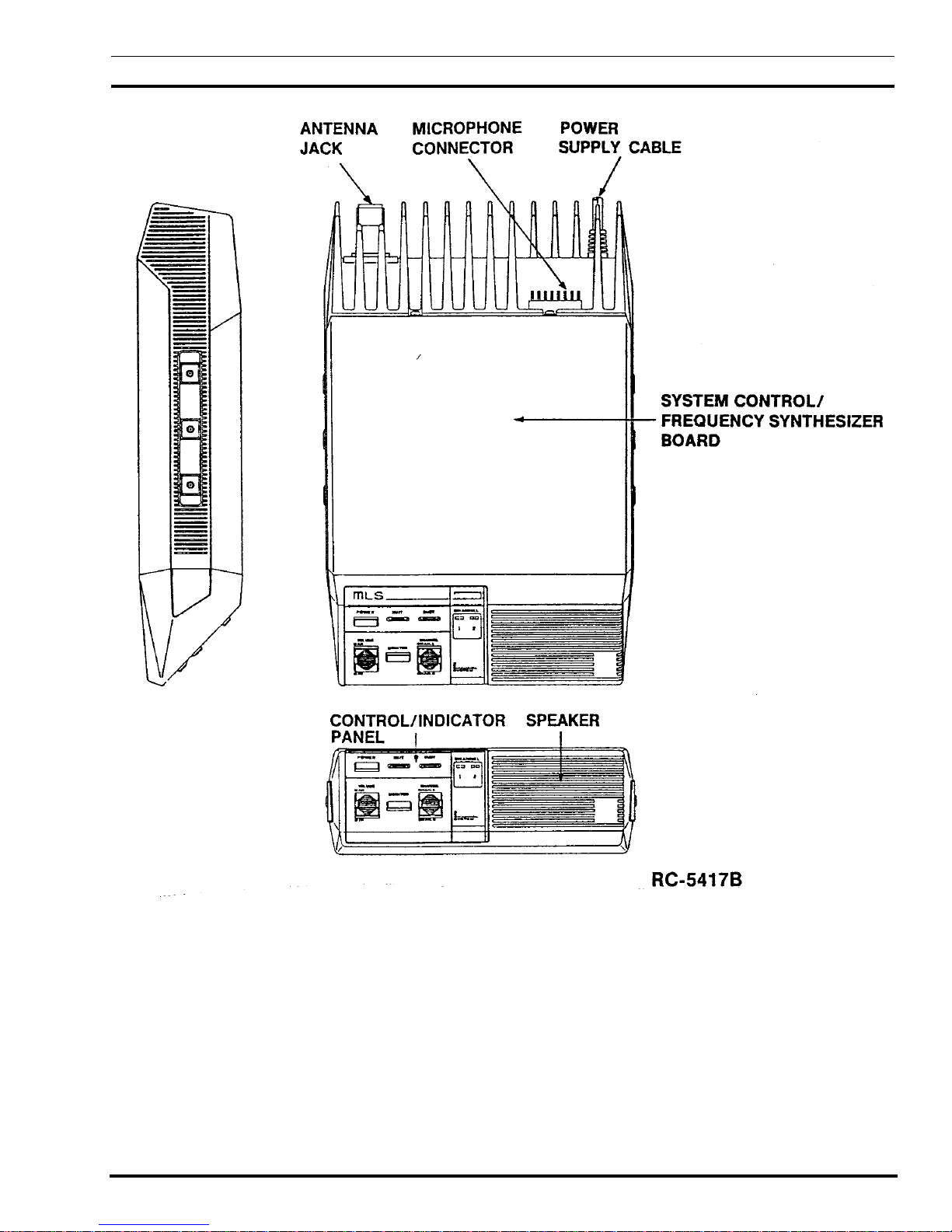
Frequency Synthesizer Board (A801), a
Transmitter/Receiver Board (A802) and a Front
Panel/Control Unit (A803 and A804).
The circuitry also consists of Control Indicator Panel
(A804), an internal speaker, an antenna jack, a connector
for the microphone, and a power supply cable (refer to
Figure 1 – Mobile Layout Diagram).
No power supply is used since the highest supply
voltage required for the operation of the radio is provided
by the vehicle battery. The radio is designed for
operatio n in a 12-volt, negative gr ound, ve hicular s ystem
or as an AC-powered mobile.
Access to each circuit board is easily achieved by
loosening four (4) screws in the rear of the top and bottom
covers, then removing each cover. All tuning controls are
also accessible with the covers removed.
Access to the Control and Indicator circuitry can be
achieved by removing the four (4) screws securing the
front panel to the chassis.
Transmitter
The Transmitter circuit consists of a broadband,
fixed-tuned driver module and a power amplifier.
The RF power output level is internally adjustable for
rated power output. Once the level is set, a sensing
control circuit holds the power constant over the
temperature and/or voltage variations within specified
limits.
Receiver
The dual conversion receive circuit consists of a
29.7–42/42-50 MHz front end section and two mixer/IF
sections operating at 20.8 MHz and 455 kHz. The receive
circuit also contains a squelch and audio section. The
audio section provides a 4-Watt audio output into a 4-ohm
load (internal speaker or external speaker).
Frequency Synthesizer
The synthesizer drives the transmit circuit exciter and
the receive circuit first mixer and consists of a synthesizer
chip, a prescaler, a reference oscillator, and the voltagecontrolled oscillators (VCOs). The synthesized frequenc y
is controlled by the personality EEPROM and applied to
the Transmitter/Receiver board.
An Electrically Erasable PROM (EEPROM), on the
System Control and Frequency Synthesizer Board (A801)
stores the binary data for the transmit and receive
frequencies, Channel Guard tones, digital codes, and CCT
timing periods. The EEPROM is field programmable and
each channel can be individually programmed or
reprogrammed for the desired transmit and receive
frequencies, CG tones, and digital codes or CCT timing.
Control Panel
The Control P anel co nsists o f the fr ont p anel ho using
an internal speaker and a plug-in module (A804) which
determines the number of channels (2 to 16) and mode of
operation (with or without scan). Refer to Maintenance
Manual LBI-38424, listed in the Table of Contents of this
publication. The panel is made of highly durable plastic
with rounded corners and recessed controls, and
indicators for passenger safety requirements (refer to the
OPERATION section for a description of the Control and
Indicator functions).
6
LBI-38435B
Figure 1 – MLS Mobile Two-Way FM Radio
7
 Loading...