

Page 1

INSTALLATION AND OPERATION MANUAL
FVTRD
10-BIT DIGITAL BI-DIRECTIONAL VIDEO OR VIDEO SYNC
+ BI-DIRECTIONAL DATA
The FVTRD(M)(S)1 supports simultaneous transmission of short-haul quality
10-bit bi-directional digital video or video sync plus bi-directional data over one
multimode or single mode optical fiber. The module is universally compatible
with major CCTV camera manufacturers and supports RS232, RS422 and 2 or
4-wire RS485 data interfaces, and most major data protocols. Plug-and-play
design ensures ease of installation and no electrical or optical adjustments
are ever required. Bi-color (Red/Green) LED indicators are provided for rapidly
ascertaining equipment operating status. These units are interchangeable
between stand-alone or card mount configurations. See Figure A on Page 5
for installation instructions.
Each Data Channel is configured for the electrical interface by means of the
“DATA SELECT” switch on the front panel. Figure 4 on Page 3 illustrates the
switch settings to set the type of data for each channel.
Figure 5 on Page 4 illustrates the specific data connections for RS232, 2-Wire
RS485 and RS422/4-Wire RS485. (This last data connection also applies to
Manchester & Bi-Phase data transmission.) It also illustrates the electrical
connections between the “Customer Equipment” and the FVTRD.
See Figures 1 – 5 for complete installation details.
INS_FVTRD_REV–
02/01/10
PAGE 1
Page 2
INSTALLATION AND OPERATION MANUAL FVTRD
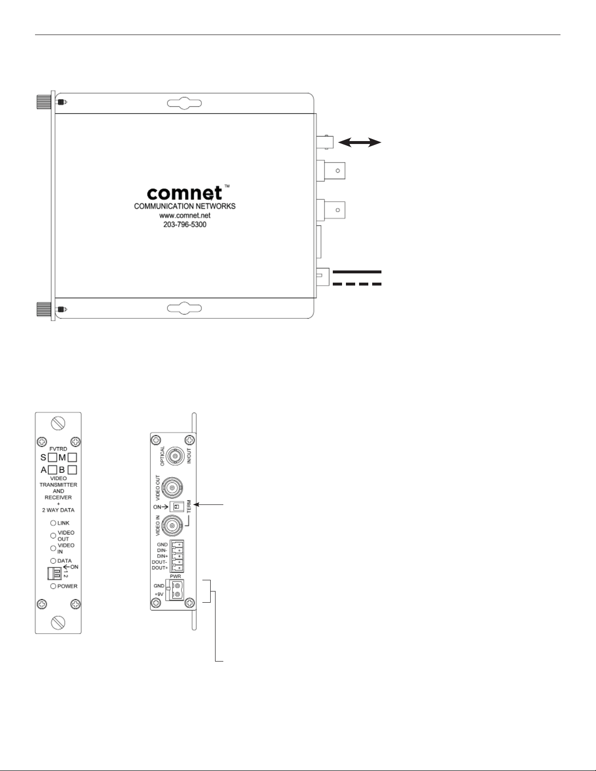
FIGURE 1 – FVTRD TRANSCEIVER
MULTIMODE OR SINGLE MODE
OPTICAL FIBER
BLACK
BLACK WITH WHITE STRIPE
FIGURE 2 – FVTRD TRANSCEIVER
REAR PANELFRONT PANEL
Video termination Switch
Set switch to TERM (Terminate)
when video is not looping to other
video devices or is the last device
in a looping configuration.
NOTE: Remove Electrical Connector
for Rack Mount Units
TECH SUPPORT: 1.888.678.9427
INS_FVTRD_REV–
02/01/10
PAGE 2
Page 3
INSTALLATION AND OPERATION MANUAL FVTRD
FIGURE 3 – LED INDICATORS
LINK VIDEO IN VIDEO OUT DATA POWER
GREEN
RED
OFF
Communication
link has been
established over
optical fiber
Communication
link has not been
established.
An active video
signal is present on
the BNC connector.
No video input
signal
An active video
signal is present on
the BNC connector.
No video output
signal
Unit powered down
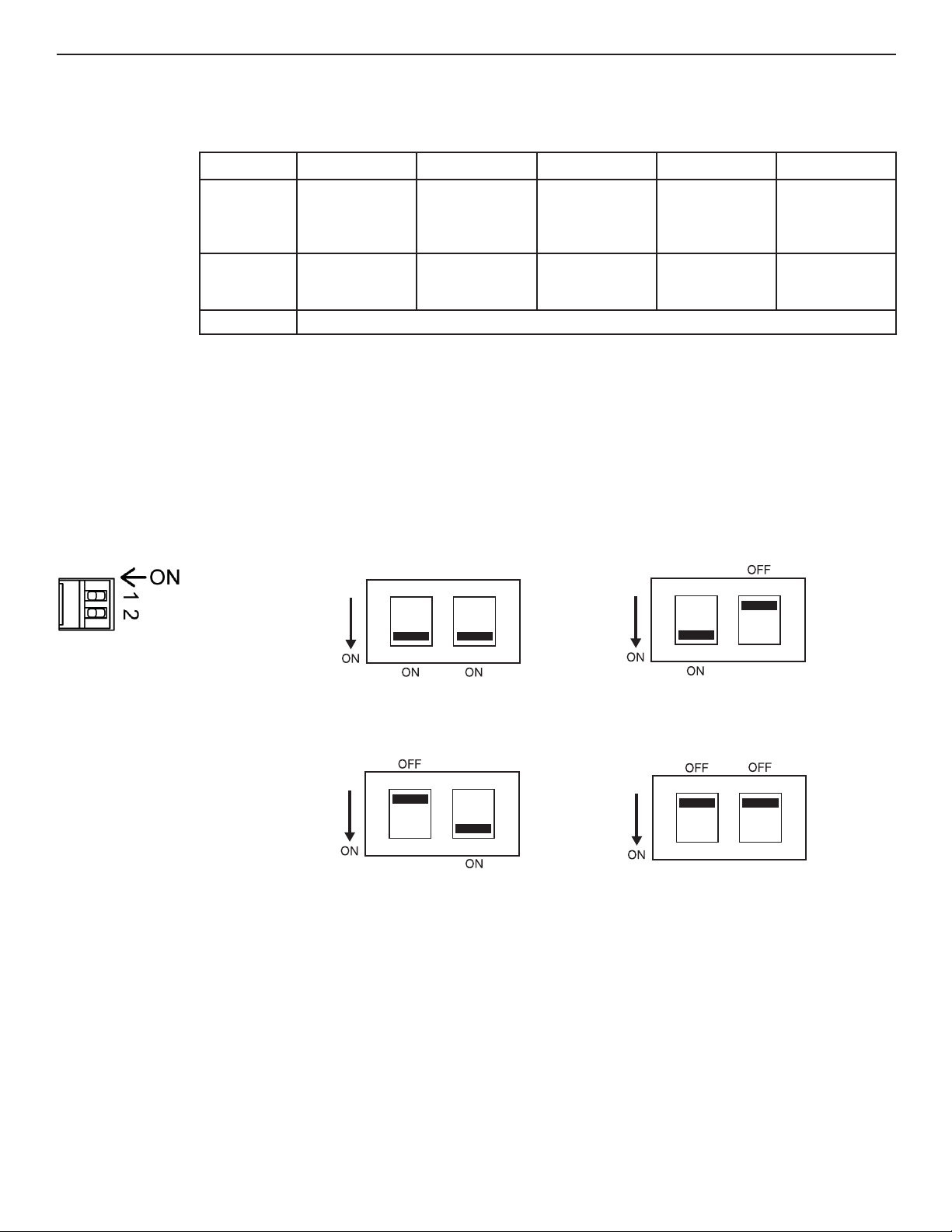
FIGURE 4 – SWITCH POSITIONS
The mode for each data channel is configured using a pair of switches on the front panel of the unit.
Front Panel
1) RS-232 DATA 2) RS-422, BI-PHASE or
1 2
An active data
signal is present on
the pins of the data
connector.
––
Unit powered up
MANCHESTER DATA
1 2
TECH SUPPORT: 1.888.678.9427
3) RS-485, 2-WIRE
SENSORNET DATA
1 2
4) RS-485, 4-WIRE DATA
1 2
INS_FVTRD_REV–
02/01/10
PAGE 3
Page 4
INSTALLATION AND OPERATION MANUAL FVTRD
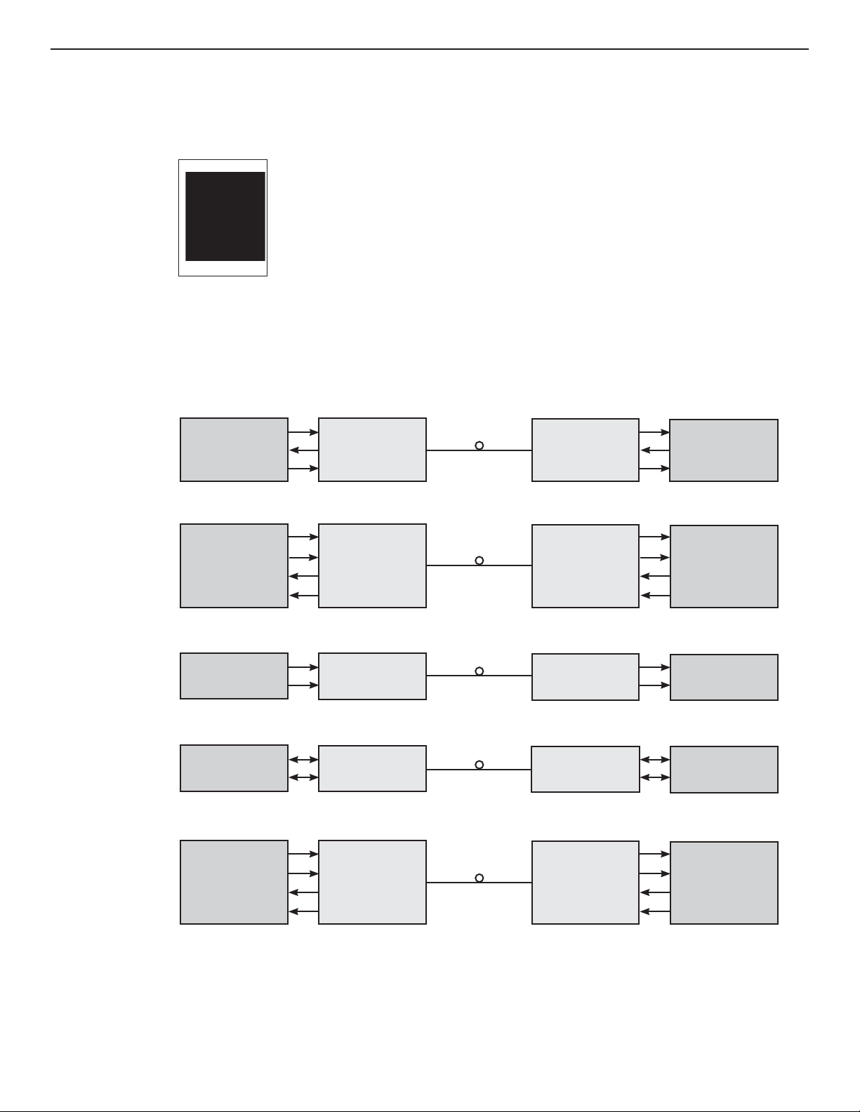
FIGURE 5 – DATA CONNECTIONS
See Page 3 for Switch Settings
RS-232
RS-422
Rear Panel
1) RS232
1 DIN (–)
2 DOUT (–)
3 Ground
Customer
Equipment FVTRD ”A”
Data Transmit
Data Receive
Signal Ground
Data Out (+)
Data Out (-)
Data In (+)
Data In (-)
DIN(-)
DOUT(-)
GND
DIN(+)
DIN(-)
DOUT(+)
DOUT(-)
2) RS422,
Manchester
& Bi-Phase
1 DIN (+)
2 DIN (–)
3 DOUT (+)
4 DOUT (–)
5 Ground
3) RS485 2-wire,
Sensornet
1 DIN (+)
2 DIN (–)
3 Ground
DOUT(-)
DIN(-)
GND
DOUT(+)
DOUT(-)
DIN(+)
DIN(-)
4) RS485 4-wire
1 DIN (+)
2 DIN (–)
3 DOUT (+)
4 DOUT (–)
5 Ground
Customer
EquipmentFV TRD “B”
Data Receive
Data Transmit
Signal Ground
Data In (+)
Data In (-)
Data Out (+)
Data Out (-)
Bi-phase or
Manchester
2-Wire
RS-485,
Sensornet
4-Wire
RS-485
TECH SUPPORT: 1.888.678.9427
Data Out (+)
Data Out (-)
Data (A)
Data (B)
Data Out (A)
Data Out (B)
Data In (A)
Data In (B)
DIN(+)
DIN(-)
DIN(+)
DIN(-)
DIN(+)
DIN(-)
DOUT(+)
DOUT(-)
DOUT(+)
DOUT(-)
DIN(+)
DIN(-)
DOUT(+)
DOUT(-)
DIN(+)
DIN(-)
Data In (+)
Data In (-)
Data (A)
Data (B)
Data In (A)
Data In (B)
Data Out (A)
Data Out (B)
INS_FVTRD_REV–
02/01/10
PAGE 4
Page 5

MECHANICAL INSTALLATION INSTRUCTIONS
INSTALLATION CONSIDERATIONS
This fiber-optic link is supplied as a Standalone/Rack module. Units
should be installed in dry locations protected from extremes of
temperature and humidity.
STANDALONE MODULE:
The unit is provided with a mounting plate with holes for two No. 6
pan head screws (3 mm or 3.55 mm). Attach the module to a solid
piece of wood using two No. 6 pan head wood screws with a
minimum penetration into the wood of 3/4 inch. (Screws not
supplied). See Figure A.
RACK MODULE:
The unit is designed to be installed in the ComNet 19-inch (483-mm)
EIA standard card-cage rack, the C1-US, C1-EU, or the C1-CH. Follow
these guidelines to install rack cards after performing module setup
procedures.
C1-US, C1-EU, C1-AU OR C1-CH CARD CAGE RACKS
CAUTION: Although the units are hot-swappable and may be installed
without turning power off to the rack, ComNet recommends that
the power supply be turned off and that the rack power supply
is disconnected from any power source. Note: Remove electrical
connector before installing in card cage rack.
FIGURE A
Dimensions are for a standard ComNet™ one slot module
.156 [3.96 mm]
.313 [7.95 mm]
1. Make sure that the card is oriented right side up, and slide it into
the card guides in the rack until the edge connector at the back
of the card seats in the corresponding slot in the rack’s connector
panel. Seating may require thumb pressure on the top and bottom
of the card’s front panel.
CAUTION: Take care not to press on any of the LEDs.
2. Tighten the two thumb screws on the card until the front panel of
the card is seated against the front of the rack.
WARNING: Unit is to be used with a Listed Class 2 or LPS power supply rated 9-12 VDC @ 1A.
WARNING: This unit should be installed in a restricted access location; available through the use of a lock and key or other means of security. Access should
be limited to service personnel who have been instructed about the reasons for the restrictions to the location. Any and all precautions should be taken and
controlled by the authority responsible for the location.
IMPORTANT SAFEGUARDS:
A) Elevated Operating Ambient - If installed in a closed or multi-unit rack assembly, the operating ambient temperature of the rack environment may be
greater than room ambient. Therefore, consideration should be given to installing the equipment in an environment compatible with the maximum ambient
temperature (Tma) specified by the manufacturer.
B) Reduced Air Flow - Installation of the equipment in a rack should be such that the amount of air flow required for safe operation of the equipment is not
compromised.
3 CORPORATE DRIVE | DANBURY, CT 06810 | USA
T: 203.796.5300 | F: 203.796.5303 | TECH SUPPORT: 1.888.678.9427 | INFO@COMNET.NET
8 TURNBERRY PARK ROAD | GILDERSOME | MORLEY | LEEDS, UK LS27 7LE
T: +44 (0)113 307 6400 | F: +44 (0)113 253 7462 | INFO-EUROPE@COMNET.NET
© 2010 Communications Networks Corporation. All Rights Reserved. “ComNet” and the “ComNet Logo” are registered trademarks of Communication Networks, LLC.
INS_FVTRD_REV–
02/01/10
PAGE 5
 Loading...