

Page 1

INSTALLATION AND OPERATION MANUAL
FVT/FVR(X)MI[/M]
HD DIGITAL VISUAL INTERFACE MULTIMODE
FIBER LINK WITH HDCP / EDID / CEC
This manual serves the following
ComNet Model Numbers:
FV T1M I
FV R1M I
FV T2MI
FVR2MI
FVTRMI
FVT1MI/M
FVR1MI/M
The ComNet™ FVT/FVR(X)MI[/M] features an HDMI™ fiber link for uncompressed
high-resolution bi-directional communication with full HDCP copyright protection,
EDID and CEC connection functionality. The high-resolution signal is transmitted over
one multimode fiber using multiple wavelengths up to 1000m. Resolutions of up
to 1080p60 are supported. HDCP encryption is not affected or compromised by the
FVT/FVR(X)MI units.
The FVT/FVR(X)MI transmits pixel-for-pixel images and full 24-bit scan rate
with no contouring or bit reduction. This unit is fully compatible with HDMI™
compliant sources and monitors, supporting all possible horizontal and vertical
sync configurations. The CEC support provided by these units allows the user to
communicate with up to ten CEC-enabled devices connected via HDMI™.
A locking HDMI™ screw prevents the connectors from accidental disconnection.
Packaged in either a small stand-alone housing or the exclusive ComNet ComFit
housing, the FVT/FVR(X)MI standard size product may be either wall or rackmounted, or may be DIN-rail mounted by the addition of ComNet model DINBKT1
adaptor plate.
Bi-color (Red/Green) LED indicators are provided for rapidly ascertaining equipment
operating status. Figure 12 on Page 6 describes the indicators for each light on the unit.
The FVT/FVR(X)MI standard size (ComFit) unit is interchangeable between stand-alone or
card mount configurations, or may be DIN-rail mounted by the addition of ComNet
model DINBKT1 adaptor plate. The FVT1MI/M has a small footprint, making it suitable
for shelf- or wall-mounting where space is at a premium. See Figure A on Page 7 for
mounting instructions.
INS_FVT/FVR(X)MI[/M]_REV– 04/20/12 PAGE 1
Page 2
INSTALLATION AND OPERATION MANUAL FVT/FVR(X)MI[/M]
GND
+Vin
HDMI
OUT
GND
+Vin
HDMI
OUT
GND
+Vin
HDMI
IN
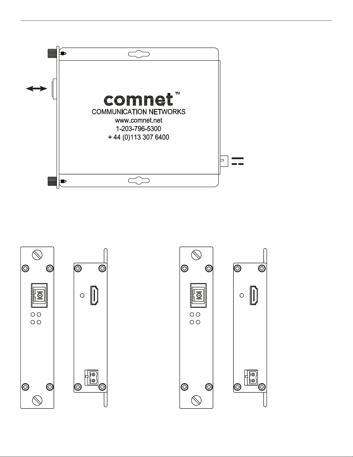
FIGURE 1 – FVT/FVR1MI SINGLE FIBER
MULTIMODE
OPTICAL
FIBER
BLACK
BLACK WITH WHITE STRIPE
Power Supply:
Surface Mount: 8-15 VDC @ 0.125A
Rack Mount: From Rack
FVR1MI
RECEIVER
FIBER
LNK
TX
1 CH
HDMI
VID
RX
FIGURE 3 – FVT1MI TRANSMITTERFIGURE 2 – FVR1MI RECEIVER
REAR PANEL REAR PANELFRONT PANEL FRONT PANEL
FVT1MI
1 CH
HDMI
OUT
HDMI
TRANSMITTER
FIBER
LNK
TX
VID
RX
NOTE: Remove Electrical Connector
for Rack Mount Units
HDMI
IN
GND
+Vin
Tech SupporT: 1.888.678.9427
GND
+Vin
INS_FVT/FVR(X)MI[/M]_REV– 04/20/12 PAGE 2
Page 3
INSTALLATION AND OPERATION MANUAL FVT/FVR(X)MI[/M]
GND
+Vin
HDMI
OUT
HDMI
OUT
GND
+Vin
HDMI
OUT
HDMI
OUT
GND
+Vin
HDMI
IN
HDMI
IN
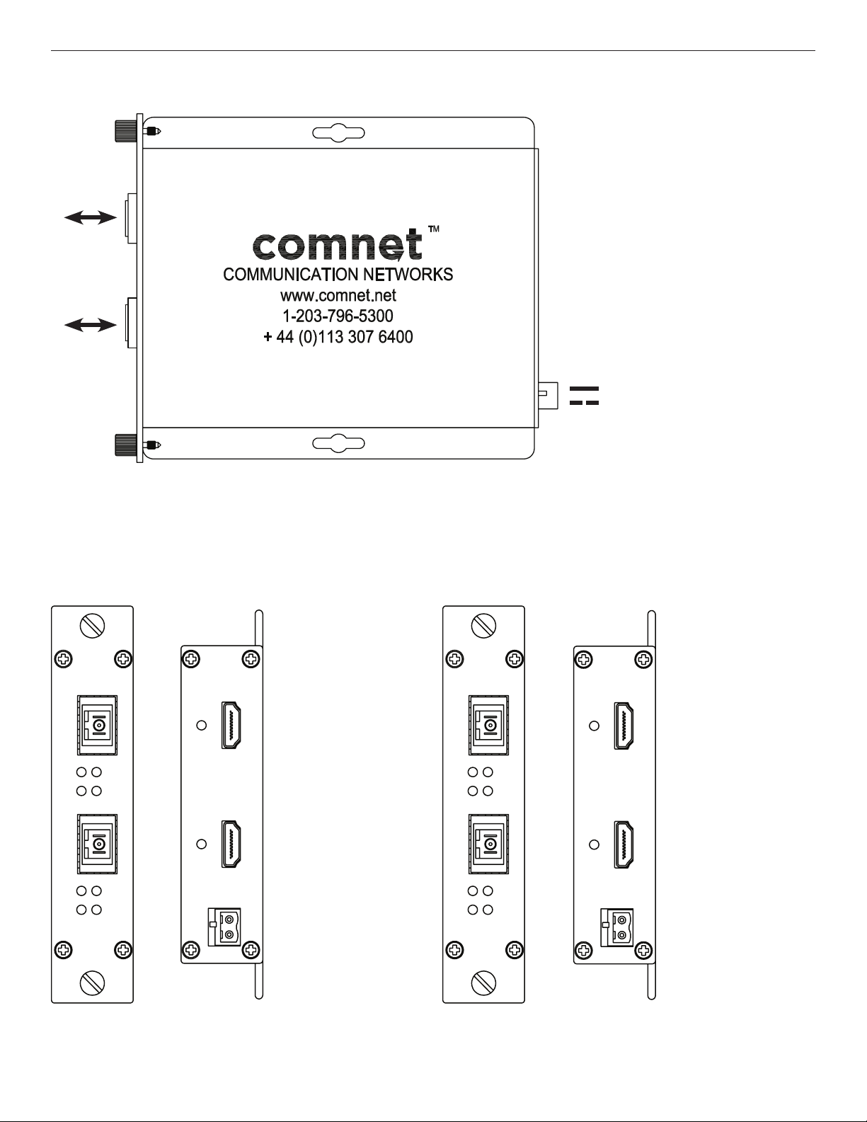
FIGURE 4 – FVT/FVR2MI TWO FIBER
MULTIMODE
OPTICAL
FIBER
BLACK
BLACK WITH WHITE STRIPE
Power Supply:
Surface Mount: 8-15 VDC @ 0.250A
Rack Mount: From Rack
FVR2MI
RECEIVER
FIBER
LNK
TX
FIBER
LNK
TX
2 CH
HDMI
VID
RX
VID
RX
FIGURE 6 – FVT2MI TRANSMITTERFIGURE 5 – FVR2MI RECEIVER
REAR PANEL REAR PANELFRONT PANEL FRONT PANEL
FVT2MI
2 CH
HDMI
TRANSMITTER
FIBER
LNK
TX
LNK
TX
VID
RX
FIBER
VID
RX
GND
+Vin
HDMI
OUT
HDMI
OUT
NOTE: Remove Electrical Connector
for Rack Mount Units
HDMI
IN
GND
+Vin
HDMI
IN
Tech SupporT: 1.888.678.9427
INS_FVT/FVR(X)MI[/M]_REV– 04/20/12 PAGE 3
Page 4

INSTALLATION AND OPERATION MANUAL FVT/FVR(X)MI[/M]
GND
+Vin
HDMI
IN
HDMI
OUT
GND
+Vin
HDMI
IN
HDMI
OUT
FIGURE 7 – FVTRMI TRANSCEIVER
MULTIMODE
OPTICAL
FIBER
BLACK
BLACK WITH WHITE STRIPE
Power Supply:
Surface Mount: 8-15 VDC @ 0.250A
Rack Mount: From Rack
FIGURE 8 – FVTRMI
REAR PANELFRONT PANEL
FVTRMI
1CHHDMI TX
1CHHDMIRX
TX
FIBER
RX
FIBER
VID
RX
VID
RX
GND
+Vin
LNK
TX
LNK
TX
HDMI
IN
HDMI
OUT
NOTE: Remove Electrical Connector
for Rack Mount Units
Tech SupporT: 1.888.678.9427
INS_FVT/FVR(X)MI[/M]_REV– 04/20/12 PAGE 4
Page 5

INSTALLATION AND OPERATION MANUAL FVT/FVR(X)MI[/M]
FIBER
GND
+Vin
HDMI
OUT
TM
FVR1MI/M
1CHA NNEL HDMI
MINI RECEIVER
TX
RX
LINK
VIDEO
FIGURE 9 – FVR1MI/M MINI SINGLE FIBER RECEIVER
FVR1MI/M
1CHA NNEL HDMI
MINI RECEIVER
FIBER
HDMI
TM
OUT
MULTIMODE
OPTICAL
FIBER
LINK
VIDEO
RX
TX
GND
+Vin
BLACK
BLACK W/ WHITE STRIPE
Power Supply: 8-15 VDC @ 0.125A
FIGURE 10 – FVT1MI/M MINI SINGLE FIBER TRANSMITTER
FVT1MI/M
1CHA NNEL HDMI
MULTIMODE
OPTICAL
FIBER
MINI TRANSMITTER
FIBER
LINK
VIDEO
RX
TX
HDMI
TM
OUT
GND
+Vin
BLACK
BLACK W/ WHITE STRIPE
Power Supply: 8-15 VDC @ 0.125A
FIGURE 11 – FVT/FVR1MI/M MINI SINGLE FIBER
REAR PANELFRONT PANEL
Tech SupporT: 1.888.678.9427
INS_FVT/FVR(X)MI[/M]_REV– 04/20/12 PAGE 5
Page 6

INSTALLATION AND OPERATION MANUAL FVT/FVR(X)MI[/M]
FIGURE 12 – LED INDICATORS
LINK VIDEO TX RX
SOLID
GREEN
FLASH
GREEN
OFF Unit powered down. Sink Power Off Source Cable Disconnected Sink Cable Disconnected
NOTE: “Source” refers to the HDMI™ Input (e.g. Blu-Ray player, Camera or Set Top Box).
Communication link has
been established over
optical fiber
Communication link has
not been established over
optical fiber
“Sink” refers to the HDMI
Sink Power On Source Cable OK Sink Cable OK
N/A N/A N/A
™
output device, (e.g. Monitor).
Tech SupporT: 1.888.678.9427
INS_FVT/FVR(X)MI[/M]_REV– 04/20/12 PAGE 6
Page 7

MECHANICAL INSTALLATION INSTRUCTIONS
INSTALLATION CONSIDERATIONS
This fiber-optic link is supplied as a Standalone/Rack module. Units should
be installed in dry locations protected from extremes of temperature and
humidity.
C1-US, C1-EU, C1-AU OR C1-CH CARD CAGE RACKS
CAUTION: Although the units are hot-swappable and may be installed
without turning power off to the rack, ComNet recommends that the
power supply be turned off and that the rack power supply is disconnected
from any power source. Note: Remove electrical connector before
installing in card cage rack.
1. Make sure that the card is oriented right side up, and slide it into the
card guides in the rack until the edge connector at the back of the card
seats in the corresponding slot in the rack’s connector panel. Seating
may require thumb pressure on the top and bottom of the card’s front
panel.
CAUTION: Take care not to press on any of the LEDs.
2. Tighten the two thumb screws on the card until the front panel of the
card is seated against the front of the rack.
WARNING: Unit is to be used with a Listed Class 2 or LPS power supply.
FIGURE A
Dimensions are for a standard ComNet™ one slot module
.156 [3.96 mm]
.313 [7.95 mm]
IMPORTANT SAFEGUARDS:
A) Elevated Operating Ambient - If installed in a closed or multi-unit rack
assembly, the operating ambient temperature of the rack environment may
be greater than room ambient. Therefore, consideration should be given to
installing the equipment in an environment compatible with the maximum
ambient temperature (Tma) specified by the manufacturer.
B) Reduced Air Flow - Installation of the equipment in a rack should be such
that the amount of air flow required for safe operation of the equipment is not
compromised.
FIGURE B
Dimensions are for a ComNet™ mini long tall module
3 CORpORATE DRIVE | DANbuRy, CT 06810 | uSA
T: 203.796.5300 | F: 203.796.5303 | TECH SuppORT: 1.888.678.9427 | INFO@COmNET.NET
8 TuRNbERRy pARK ROAD | GILDERSOmE | mORLEy | LEEDS, uK LS27 7LE
T: +44 (0)113 307 6400 | F: +44 (0)113 253 7462 | INFO-EuROpE@COmNET.NET
© 2012 Communications Networks Cor poration. All Rights Reser ved. “ComNet ” and the “ComNet L ogo” are registered tr ademarks of Communication Net works, LLC .
INS_FVT/FVR(X)MI[/M]_REV– 04/20/12 PAGE 7
 Loading...