

Page 1

INSTALLATION AND OPERATION MANUAL
FVT1C1B(M,S)1-M
8-BIT DIGITALLY ENCODED VIDEO MINI TRANSMITTER
WITH CONTACT CLOSURE
The FVT1C1B-M video mini-transmitter supports transmission of a fixed video and
a contact closure signal using an 8-bit digitally encoded signal on one multimode
or single mode fiber optic cable. These units are completely transparent to and
universally compatible with any NTSC, PAL, or SECAM CCTV camera systems.
The FVT1C1B-M video transmitter is compatible with the FVR4C4B receivers.
Installation requires no electrical or optical adjustments.
The transmitter incorporates a bi-color (Red/Green) indicating LED for monitoring
proper system operation.
The unit operates on 5VDC power.
The FVT1C1B mini unit operates as a standalone module only.
See Figures 1 – 3 for complete installation details.
INS_FVT1C1B_REV–
12/06/10
PAGE 1
Page 2
INSTALLATION AND OPERATION MANUAL FVT1C1B(M,S)1-M
FIGURE 1 – FVT1C1B(M,S)1-M
5VDC INPUT
+5V Center
GND Shield
MULTIMODE OR
SINGLE MODE
OPTICAL FIBER
FIGURE 2 – FVT1C1B(M,S)1-M FIGURE 3 – LED INDICATOR
REAR PANELFRONT PANEL
VIDEO PRESENT
GREEN
A Video signal is
present.
RED
No Video signal is
present.
OFF
Unit not powered up.
FIGURE 4 – CONTACT SETTINGS
Open Circuit 3.3V
Current Sink to Close ≤ 1mA
CONTACT
GROUND
TECH SUPPORT: 1.888.678.9427
INS_FVT1C1B_REV–
12/06/10
PAGE 2
Page 3

MECHANICAL INSTALLATION INSTRUCTIONS
INSTALLATION CONSIDERATIONS
This fiber-optic link is supplied as a Standalone module. Units should
be installed in dry locations protected from extremes of temperature
and humidity.
WARNING: Unit is to be used with a Listed Class 2 or LPS power supply rated
5 VDC @ 1A.
IMPORTANT SAFEGUARDS:
A) Elevated Operating Ambient - If installed in a closed or multi-unit rack
assembly, the operating ambient temperature of the rack environment may
be greater than room ambient. Therefore, consideration should be given to
installing the equipment in an environment compatible with the maximum
ambient temperature (Tma) specified by the manufacturer.
B) Reduced Air Flow - Installation of the equipment in a rack should be such
that the amount of air flow required for safe operation of the equipment is
not compromised.
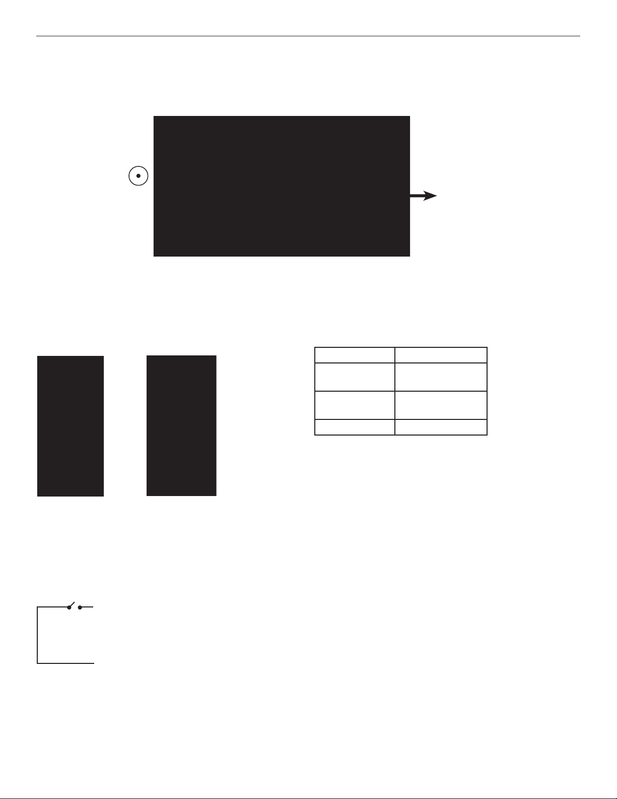
FIGURE A
Dimensions are for a standard ComNet™ “mini” module
3 CORPORATE DRIVE | DANBURY, CT 06810 | USA
T: 203.796.5300 | F: 203.796.5303 | TECH SUPPORT: 1.888.678.9427 | INFO@COMNET.NET
8 TURNBERRY PARK ROAD | GILDERSOME | MORLEY | LEEDS, UK LS27 7LE
T: +44 (0)113 307 6400 | F: +44 (0)113 253 7462 | INFO-EUROPE@COMNET.NET
© 2011 Communications Networks Corporation. All Rights Reserved. “ComNet” and the “ComNet Logo” are registered trademarks of Communication Networks, LLC.
INS_FVT1C1B_REV–
12/06/10
PAGE 3
 Loading...